bar code reader bcl 40 with integrated decoder connector ...€¦ · the data set which is...
TRANSCRIPT

Leuze electronic
Bar Code Reader BCL 40 with Integrated DecoderConnector Unit MA 10
Technical Description

© All rights reserved, especially the right of reproduction and translation. Duplication or reproduction in any form may only be carried out with the expressed written consent of Leuze electronic GmbH & Co. We reserve the right to make changes for the technical improvement of the product.
Leuze electronic BCL 40 1
Leuze electronic Table of contents
1 General Information........................................................................................................... 5
1.1 Explanation of Symbols ....................................................................................................... 51.2 Definition of Terms............................................................................................................... 51.3 Declaration of Conformity .................................................................................................... 7
2 Safety Notices .................................................................................................................... 8
2.1 Safety Standards ................................................................................................................. 82.2 Intended Use........................................................................................................................ 82.3 Working Safely ..................................................................................................................... 9
3 Description ....................................................................................................................... 10
3.1 The Bar Code Readers BCL 40 ......................................................................................... 103.2 Features of the BCL 40...................................................................................................... 103.2.1 Performance features .................................................................................................................. 103.2.2 Added features with MA 10.......................................................................................................... 113.2.3 Modular Concept ......................................................................................................................... 11
3.3 Construction....................................................................................................................... 143.3.1 BCL 40/device construction ......................................................................................................... 143.3.2 Device construction MA 10 .......................................................................................................... 15
4 Specifications................................................................................................................... 16
4.1 Technical Data BCL 40 Standard Version ......................................................................... 164.2 Technical Data BCL 40 with Heating ................................................................................. 174.3 Technical Data MA 10........................................................................................................ 184.4 Dimensioned drawings....................................................................................................... 194.5 Optical Data ....................................................................................................................... 204.5.1 Type overview.............................................................................................................................. 214.5.2 Sweep principle ........................................................................................................................... 214.5.3 Optics variants ............................................................................................................................. 224.5.4 Reading curves BCL 40 standard version ................................................................................... 234.5.5 Reading curves BCL 40 with heating........................................................................................... 25
5 Accessories / Order Designation ................................................................................... 27
5.1 Accessories........................................................................................................................ 275.1.1 Bar code reader BCL 40 .............................................................................................................. 275.1.2 Connector and interface unit MA 10 ............................................................................................ 275.1.3 Mounting accessories .................................................................................................................. 285.1.4 Cable accessories ....................................................................................................................... 295.1.5 Software....................................................................................................................................... 29
6 Installation ........................................................................................................................ 30
6.1 Storage, Transportation ..................................................................................................... 306.2 Mounting ............................................................................................................................ 316.2.1 Types of Mounting ....................................................................................................................... 316.2.2 Device Arrangement .................................................................................................................... 34
6.3 Connection......................................................................................................................... 37

2 BCL 40 Leuze electronic
Table of contents Leuze electronic
6.3.1 Connecting the BCL 40 for "Stand Alone" Operation ...................................................................386.3.2 Connecting the BCL 40 with the connector unit MA 10................................................................406.3.3 Wire Lengths and Shielding .........................................................................................................50
6.4 Disassembling, Packing, Disposing ................................................................................... 50
7 Commissioning ................................................................................................................ 51
7.1 Measures to be performed prior to the first commissioning ............................................... 517.2 Function Test ..................................................................................................................... 537.3 Setting the Parameters ...................................................................................................... 537.3.1 Parameter sets .............................................................................................................................547.3.2 Service Operating Mode ..............................................................................................................567.3.3 Setting Parameters "Offline".........................................................................................................577.3.4 Setting Parameters "Online".........................................................................................................587.3.5 Setting the Bar Code Parameters Using "autoConfig" .................................................................58
8 Operation .......................................................................................................................... 60
8.1 Display Elements ............................................................................................................... 608.2 Important Functions During Operation............................................................................... 618.3 Error Handling.................................................................................................................... 61
9 Communicating with the Device..................................................................................... 62
9.1 Installation of the "BCL Configuration Tool" software ........................................................ 629.2 Graphic configuration using the "BCL Configuration Tool" software.................................. 639.2.1 Code menu...................................................................................................................................649.2.2 Output menu ................................................................................................................................669.2.3 Control..........................................................................................................................................679.2.4 Communication ............................................................................................................................689.2.5 Reference code............................................................................................................................709.2.6 Sensor..........................................................................................................................................719.2.7 Switching outputs .........................................................................................................................72
9.3 Overview of Commands and Parameters .......................................................................... 739.3.1 General "Online" Commands .......................................................................................................749.3.2 "Online" Commands for System Control ......................................................................................779.3.3 "Online" Commands for System Checking...................................................................................789.3.4 "Online" Commands for Querying Statistical Data .......................................................................809.3.5 "Online" Commands for Parameter Set Operations .....................................................................81
10 Maintenance ..................................................................................................................... 83
10.1 General Maintenance Information...................................................................................... 8310.2 Repairs, Servicing.............................................................................................................. 83
11 Appendix........................................................................................................................... 84
11.1 ASCII Table........................................................................................................................ 8411.2 Example Bar Code Label Types ........................................................................................ 8811.2.1 Module 0.3 ...................................................................................................................................8811.2.2 Module 0.5 ...................................................................................................................................89

Leuze electronic BCL 40 3
Leuze electronic Figures and tables
Figure 3.1: Possible combinations of the BCL 40 / MA 10 ...........................................................12Figure 3.2: Networking possibilities using the multiNet plus.........................................................13Figure 3.3: BCL 40/device construction........................................................................................14Figure 3.4: Connector unit MA 10.................................................................................................15Table 4.1: General Specifications BCL 40 Standard Version......................................................17Table 4.2: General Specifications BCL 40 with Heater ...............................................................17Table 4.3: General Specifications MA 10 ....................................................................................18Figure 4.1: Dimensioned drawing BCL 40....................................................................................19Figure 4.2: Dimensioned drawing MA 10 .....................................................................................19Figure 4.3: The most important characteristics of a bar code ......................................................20Table 4.4: Type overview ............................................................................................................21Figure 4.4: Sweep principle of the raster scanner ........................................................................21Figure 4.5: Sweep principle for the line scanner ..........................................................................22Figure 4.6: Reading curves BCL 40 standard version, optic variants N and M ............................23Figure 4.7: Reading curves BCL 40 standard version, optic variants F and L .............................24Figure 4.8: Reading curves BCL 40 with heating, optic variants M and L ....................................25Figure 4.9: Reading curves BCL 40 with heating, optic variant F.................................................26Table 5.1: Accessories/Order Designation BCL 40.....................................................................27Table 5.2: Accessories/Order Designation MA 10 ......................................................................27Figure 5.1: Mounting device BT 56...............................................................................................28Figure 5.2: Mounting device BT 57...............................................................................................28Figure 5.3: Connection cable between the BCL 40 and MA 10....................................................29Figure 5.4: Connection cable between BCL 40 "stand alone" ......................................................29Figure 6.1: Device nameplates MA 10 and BCL 40 .....................................................................30Figure 6.2: Mounting example BCL 40 "stand alone" ...................................................................31Figure 6.3: Mounting example for the combined BCL 40 / MA 10 unit .........................................32Figure 6.4: Mounting examples for the BCL 40 and MA 10 mounted independently ...................33Figure 6.5: Minimum space requirements for installation .............................................................35Figure 6.6: Application example "conveyor chain" .......................................................................36Figure 6.7: Connecting the BCL 40 for "Stand Alone" Operation .................................................38Figure 6.8: Connection diagram for the Sub D connector plug ....................................................39Table 6.1: Wiring description BCL 40..........................................................................................40Figure 6.9: Connecting the BCL 40 with the connector unit MA 10..............................................40Figure 6.10: Disconnecting the ribbon cable inside the MA 10 ......................................................41Figure 6.11: Wiring to the terminal strip without screwing down or soldering.................................42Figure 6.12: Position of the connections for the MA 10..................................................................42Figure 6.13: Connecting the MA 10 to a RS 485 Host ...................................................................44Figure 6.14: Connecting the MA 10 to a RS 232 Host ...................................................................44Figure 6.15: Connecting the MA 10 as active subscriber to a TTY Host........................................45Figure 6.16: Connecting the MA 10 as passive subscriber to a TTY Host .....................................45Figure 6.17: Connecting the MA 10 to a RS 422 Host ...................................................................46Figure 6.18: Connection of the switching input with an external switching voltage ........................47Figure 6.19: Connection of the switching input without an external switching voltage ...................47Figure 6.20: Position of the solder jumpers JL5 and JL6 ...............................................................48Figure 6.21: Operating voltage used as the switching voltage .......................................................49Figure 6.22: Switching voltage connected externally (galvanically decoupled)..............................49Figure 7.1: Control elements of the MA 10...................................................................................51Figure 7.2: Block diagram storage concept for parameter sets....................................................55

4 BCL 40 Leuze electronic
Figures and tables Leuze electronic
Figure 7.3: Connecting the service interface to a PC or terminal ................................................. 56Figure 9.1: Installation window ..................................................................................................... 62Figure 9.2: Installation directory ................................................................................................... 63Figure 9.3: "Decode" menu, standard setting............................................................................... 64Figure 9.4: Properties of the Decode menu, standard setting ...................................................... 65Figure 9.5: "Output" menu ............................................................................................................ 66Figure 9.6: "Control" menu, standard setting................................................................................ 67Figure 9.7: "Communication" menu, standard setting .................................................................. 68Figure 9.8: Properties of the Communication menu, standard setting ......................................... 69Figure 9.9: "Reference code" menu ............................................................................................. 70Figure 9.10: "Sensor" menu, standard setting................................................................................ 71Figure 9.11: "Switch 1" menu, standard setting.............................................................................. 72Table 11.1: ASCII Table ................................................................................................................ 87Figure 11.1: Bar code sample labels (module width 0.3) ............................................................... 88Figure 11.2: Bar code sample labels (module 0.5)......................................................................... 89

Leuze electronic General Information
Leuze electronic BCL 40 5
TN
T 3
5/7-
24V
1 General Information
1.1 Explanation of Symbols
The symbols used in this operating manual are explained below.
Attention!
Pay attention to passages marked with this symbol. Failure to heed this information can leadto injuries to personnel or damage to the equipment.
Attention Laser!
This symbol warns of possible danger through hazardous laser radiation.
Notice!
This symbol indicates text passages containing important information.
1.2 Definition of Terms
ActivationInitiates a read process, e.g. by triggering the switched input.
ASCIIStandard character set (American Standard Code for Information Interchange) with 128characters. Each character of the ASCII character set has been assigned a number from 0to 127. This number is usually displayed in decimal format, but can also be displayed in hex-adecimal or octal.
autoConfigThe function integrated into the bar code reader which automatically recognises the typeand number of characters of the code to be read in.
autoControlThe function integrated into the bar code reader used to monitor the read quality.
Bar codeAn arrangement of parallel bars and spaces which are arranged according to a standardisedprotocol such that they have a certain numeric or alphanumeric meaning.
DeactivationEnd a read process, e.g. by using an online command.
Decoder/Decoding systemThe microprocessor control unit which translates the scanned bar code information into asimple signal that can be processed further.
Frame protocolTransfer protocol for the data transfer between the bar code reader and the host.

General Information Leuze electronic
6 BCL 40 Leuze electronic
Hex.Abbreviation for hexadecimal notation.
HostExternal computer or programmable logic controller (PLC) which is connected to the barcode reader via a serial interface and is used to further process the decoded bar code infor-mation.
Interface moduleElectronic component in the connector unit MA 10 which carries out the electrical adjust-ment of the various serial interface types (e.g. RS 232, RS 422, etc.).
LabelBarcode label
multiNetThe network developed by Leuze for networking together several bar code readers.
No ReadRead failure; a read process was initiated but a label could not be decoded.
Online commandA command which is sent directly to the bar code reader from the host or a computerconnected to the interface.
Output formatDetermines the data format of the bar code information output from the decoder.
Parameter setThe data set which is permanently stored in the bar code reader and contains all of thedevice settings.
PDProgramming device
PLCProgrammable logic controller. A PLC usually can be used as a host.
PostfixTrailer of the data transfer protocol (frame protocol) between the bar code reader and thehost.
PrefixHeader of the data transfer protocol (frame protocol) between the bar code reader and thehost.
ProtocolInterface protocol of the serial interface.
Raster scannerThe sweep method of the scanner laser beam. It is used when the lines of the bar code canonly be applied vertically with respect to the direction of travel, or when the code must beread while stationary.
Read qualityThe read quality can be monitored using the autoControl function. The relationship of thenumber of successful reads to the total number of reads is determined and monitored.

Leuze electronic General Information
Leuze electronic BCL 40 7
TN
T 3
5/7-
24V
Reference codeComplete or partial bar code information which can be compared to the read label, e.g. toselect a path for packages.
ScannerBar code reader that optically scans the bar code with a laser beam.
Switched inputBipolar input for connecting a sensor or switch used for initiating a read process or foracquiring a reference code.
Switched outputConnection for output of status or event messages, e.g. after a failed read.
Teach-InProgramming a reference code using an example bar code.
1.3 Declaration of ConformityThe bar code readers BCL 40 and the connector unit MA 10 have been developed andproduced in accordance with the applicable European standards and directives.
Notice!
The corresponding declaration of conformity can be requested from the manufacturer.
The manufacturer of the product, Leuze electronic GmbH & Co. in D-73277 Owen/Teck,possesses a certified quality assurance system in accordance with ISO 9001.

Safety Notices Leuze electronic
8 BCL 40 Leuze electronic
2 Safety Notices
2.1 Safety Standards The bar code readers BCL 40 and the connector unit MA 10 have been developed, producedand tested subject to the applicable safety standards. They correspond to the state of the art.
2.2 Intended Use
Attention!
The protection of personnel and the device cannot be guaranteed if the device is operatedin a manner not corresponding to its intended use.
Bar code readers of the type BCL 40 are conceived as stationary, high-speed scanners withintegrated decoders for all current bar codes used for automatic object recognition.
The connector and interface unit MA 10 simplifies the connection of the bar code reader oftype BCL 40 and adapts to various host interfaces. Connection to other bar code readers isnot authorised.
In particular, unauthorised use includes:
• rooms with explosive atmospheres • operation for medical purposes
Fields of applicationThe bar code readers BCL 40 with optional connector unit MA 10 are conceived particularlyfor the following fields of application:
• labelling and packaging machines• automatic analysers• space-critical bar code reading tasks• storage and conveying technologies, in particular for object identification on
fast-moving conveyor belts• pharmaceutical industry

Leuze electronic Safety Notices
Leuze electronic BCL 40 9
TN
T 3
5/7-
24V
2.3 Working Safely
Attention Laser Radiation!
The BCL 40 are laser devices of the Laser Protection Class 2. Do not look directly into the laser beam. Observe the applicable legal and local regulationsfor the operation of laser units.
Attention!
Access to or changes on the device, except where expressly described in this operatingmanual, is not authorised.
Safety RegulationsObserve the locally applicable legal regulations and the rules of the employer’s liability insur-ance association.
Qualified PersonnelMounting, commissioning and maintenance of the device must only be carried out by qual-ified personnel. Electrical work must be carried out by a certified electrician.

Description Leuze electronic
10 BCL 40 Leuze electronic
3 Description
3.1 The Bar Code Readers BCL 40The bar code reader BCL 40 is a high-speed scanner with integrated decoder for all barcodes currently in use, e.g. 2/5 Interleaved, EAN, etc.
The many possible configurations of the device allow its adaptation to a multitude of readingtasks. Due to its compact size and short minimum reading distance, the BCL 40 can also beused in very compact spaces.
Together with the connector unit MA 10, it can easily be adapted for use with various inter-faces, thus allowing additional processing by other systems. The MA 10 connector unit canalso be used to network together several BCL 40 devices and to simplify electrical installa-tion.
On demand, the BCL 40 can be equipped with an integrated heater. This variant is usedprimarily in low-temperature and outdoor applications. The optional heater is constructedsuch that no heat transfer occurs between the separately mounted technical unit and thescanner housing. In addition, the front cover of the device is heated, preventing the forma-tion of condensation which would affect the reading function. The reading curves differ withrespect to the standard type in the construction of the front cover, which is modified byheating filaments.
3.2 Features of the BCL 40
3.2.1 Performance features
• Compact device dimensions (W x H x D) 90 x 120 x 43mm• Reading height of 70 mm at a distance of 10mm• Maximum reading distance up to 700mm (depending on type of optics)• Raster or line scanner (R1 = raster, S = single line) max. 1200scans/s• A switched input for triggering a read process using sensors• Automatic monitoring of the read quality with the "autoControl" function• Automatic recognition of the bar code type using "autoConfig"• All device parameters can be set by software• Heavy-duty housing of protection class IP 65 with corresponding cable• RS 232 or RS 485 interface to host• Extensive formatting possibilities for data output• Reference code (comparison code)

Leuze electronic Description
Leuze electronic BCL 40 11
TN
T 3
5/7-
24V
3.2.2 Added features with MA 10
• Device status display with 4 LEDs• RS 485 interface with electrical isolation for networking several devices• Alternative interface RS 232, RS 422 or TTY using a selectable interface module with
electrical isolation for directly connecting to the host• Two hardware switched outputs for status signals• Additional switched input for the definition of reference code 1• Simple electrical connection via double terminal clamps, i.e. both the power supply
and the interface circuits can easily be connected in series.• Heavy-duty housing of protection class IP 65• 2 parameter sets can be stored locally in the MA 10
(current parameter set, customer-specific parameter set)• Built-in RS 232 service interface for fast commissioning or troubleshooting on site
using a PC or programming device• Switch for the "autoConfig" function
3.2.3 Modular Concept
BCL 40 "Stand alone"The bar code reader BCL 40 can be operated as an individual "stand alone" (�) device.Electrical connection of the power supply, interface and switched input are centrally madevia a 15 pin SubD socket.
For connection, it is best to use the 15 conductor connection cable from Leuze. The require-ments for protection class IP 65 are fulfilled when using this cable only (see chapter 5"Accessories / Order Designation").
BCL 40 with MA 10 When using several BCL 40 units or under rough environment conditions, the installation ofone connector unit MA 10 for each BCL 40 unit is recommended.
Electrical connection, commissioning, and service can be comfortably carried out in a shortperiod of time.
The BCL 40 and MA 10 can be mounted directly together (�) or arranged separately nextto each other. When mounted separately (�), the two units are connected by a cable.Protection class IP 65 is maintained when the sealed accessory cable is used (see chapter5 "Accessories / Order Designation").

Description Leuze electronic
12 BCL 40 Leuze electronic
Figure 3.1: Possible combinations of the BCL 40 / MA 10
NetworkingUp to 31 BCL 40 bar code readers can be networked together using the connector unitMA 10 (with interface module RS 485). The devices are interconnected by connecting theindividual RS 485 interfaces in parallel.
multiNet plusIn the Leuze multiNet plus, the individual network devices sequentially transfer their data tothe network master MA 30 when requested ("polling").
The master station can also be fitted with an BCL 40, making it a complete scanner stationwhich also controls the network.
Each network device declared as a slave maintains a device address which is set in therespective MA 10 with a coding switch. If the reader unit is exchanged (BCL), the deviceaddress and all settings in the MA 10 are maintained.
The master then transmits the data of all network devices via its host interface to a primaryPLC control system or a computer, i.e. it "collects" the scanner data in the network and trans-mits them to an interface on the host computer. This reduces interface costs (CPs) and timeprogramming the software.
The MA 30/31 are suitable for use as network master devices.
� BCL 40 as"Stand alone"-device
� BCL 40 with the connector unit MA 10 mounted together
� BCL 40 and MA 10 mounted separately and connected together by a cable

Leuze electronic Description
Leuze electronic BCL 40 13
TN
T 3
5/7-
24V
Figure 3.2: Networking possibilities using the multiNet plus
Two-wire RS 485The Leuze MultiNet plus is optimised for fast transmission of scanner data to a primary hostcomputer. The multiNet plus physically consists of a two-wire RS 485 interface throughwhich the multiNet plus software protocol is controlled. Thus network connection is verysimple and inexpensive: the network connection is simply passed through to the next slave.
Interface modulesShielded, twisted pair conductors should be used for the multiNet. This allows a totalnetwork length of up to 1200m.
Connection of the network to the primary computer is made via the host interface of the MA30 which can be equipped with 4 different physical interface modules. Modules for RS 232,RS 422, TTY and RS 485 are available.
Slave MA 10
Slave MA 10
Slave MA 10
RS 232 RS 422
RS 485 or TTY
-Backup parameters
Voltage supply
Network mastermultiNet plus
MA 30
RS 485
Sensor
Sensor
Sensor
Sensor

Description Leuze electronic
14 BCL 40 Leuze electronic
3.3 Construction
3.3.1 BCL 40/device construction
Figure 3.3: BCL 40/device construction
Reading window
4 fastening threads M4 on the rear of the device
15-pin sub-D connector on the underside of the unit
Dovetail fastening grooves

Leuze electronic Description
Leuze electronic BCL 40 15
TN
T 3
5/7-
24V
3.3.2 Device construction MA 10
Figure 3.4: Connector unit MA 10
Device variations MA 10The MA 10 is available in four models:
• MA 10 100 with host interface module RS 485• MA 10 110 with host interface module RS 232• MA 10 120 with host interface module TTY• MA 10 130 with host interface module RS 422
All modules are galvanically isolated, i.e. they are EMC interference protected and immuneto differences in voltage potentials across long cable lengths.
Notice!
Only the type MA 10 100 can be used as a multiNet slave unit.
Cable screw glands PG11for the power supply
Cable screw glands PG11for the power supply
4 fastening threads M4 on the base of the device
4 Status-LEDs on the rear
Mounting holes for the BCL 40 with M4 screws
15 pin Sub-D connector
Dovetail fastening grooves

Specifications Leuze electronic
16 BCL 40 Leuze electronic
4 Specifications
4.1 Technical Data BCL 40 Standard Version
Optical DataLight source Laser diode 650nmScanning rate BCL with N, M, F optics: 1200scans/s
BCL with L optics: 900scans/sResolution 0.1mm … 1.2mm
module widthBeam deflection by means of rotating polygon mirror wheelReading distance 0 … 700mm (depending on type of optics: N, M, F, L), see
chapter 4.5.4 "Reading curves BCL 40 standard version"Reading field opening 70mm at a distance of approx. 10mm (see chapter 4.5.4
"Reading curves BCL 40 standard version")Grid (R1) 8 linesGrid field specified is the area from the first to the last laser beam as
a function of distance to the scanner22mm at 100mm scanner distance 33mm at 200mm scanner distance45mm at 300mm scanner distance65mm at 500mm scanner distance95mm at 800mm scanner distance
Single line (S) 1 lineOptical window glass with scratch-resistant Indium coatingLaser safety class 2Code types 2/5 Interleaved; Code 39; Code 128; EAN 8; 13; EAN 128;
UPC; Codabar; Add-On for EAN / UPCSoftware features selectable output format, autoConfig, autoControl, refer-
ence code comparison, multiple read, real time decoding, adjustment mode, diagnosis, reading gate control, control of switching inputs and switching outputs, etc.
Electrical dataInterface type can be switched between RS 232 and RS 485, additional
service interface (RS 232)TTY / RS 422 optional with MA 10
Baud rate 110 … 57600Bd (host interface only)Data formats data bits: 7, 8, 9
parity: None, Even, OddStop bit: 1, 2
Protocols with/without frame protocolACK/NAK, 3964 (R) RK 512, RTS/CTSX ON / X OFF, multiNet plus
Ports 1 switching inputLED green device ready (Power On)

Leuze electronic Specifications
Leuze electronic BCL 40 17
TN
T 3
5/7-
24V
Table 4.1: General Specifications BCL 40 Standard Version
4.2 Technical Data BCL 40 with HeatingThe following table is limited to the data which are different than those specified for thestandard model.
Table 4.2: General Specifications BCL 40 with Heater
Switching input 12 … 36VDC/AC voltage, selectable galvanic isolation or supplied operating voltage, max. insulation voltage: 250V (with galvanic isolation)
Operating voltage 18 … 36VPower consumption 5VA max.
Mechanical dataProtection class IP 65Weight approx. 430gDimensions (WxHxD) 120 x 90 x 43mmHousing diecast aluminium
Environmental dataAmbient temperature (operation/storage)
0°C … +40°C / -20°C … +60°C
Air humidity max. 90% rel. humidity, non-condensing Vibration IEC 68.2.6Shock IEC 68.2.27EMC IEC 801
Optical DataLight source Laser diode 660nmResolution 0.25mm … 1.0mm module widthReading distance 0 … 630mm (depending on type of optics: M, F, L)
see chapter 4.5.5 "Reading curves BCL 40 with heating"Reading field opening Depending on the distance, the reading curve is typically
approx. 20 … 70mm narrower see chapter 4.5.5 "Reading curves BCL 40 with heating"
Electrical dataOperating voltage 24VDC ± 2VPower consumption 10W max.
Mechanical dataWeight approx. 500gDimensions (WxHxD) 120 x 90 x 52mm
Environmental dataAmbient temperature (operation/storage)
-40°C … +30°C/-20°C … +60°C

Specifications Leuze electronic
18 BCL 40 Leuze electronic
4.3 Technical Data MA 10
Table 4.3: General Specifications MA 10
Mechanical dataHousing Diecast aluminiumDimensions (WxHxD) 130 x 90 x 78mmWeight approx. 740gProtection class IP 65
InterfacesType (optional) RS 232, with galvanic isolation
RS 422, with galvanic isolationRS 485, with galvanic isolationTTY, with galvanic isolation
Service interface RS 232 internal, 9 pin Sub D plug, male
Inputs/outputs2 switched inputs galvanically isolated,with supply voltage terminal for sen-
sors 12 … 36VDC/AC, insulation voltage 500V2 switched outputs can be operated galvanically isolated or not isolated
switching voltage 5 … 48V DC, max. load 500mA
Power supplyOperating voltage 18 … 36VDCPower consumption 2VA max.
Environmental dataAmbient temperature(operation/storage)
0°C … +50°C/-20°C … +60°C
Air humidity max. 90% rel. humidity, non-condensing Vibration IEC 68.2.6Shock IEC 68.2.27EMC IEC 801

Leuze electronic Specifications
Leuze electronic BCL 40 19
TN
T 3
5/7-
24V
4.4 Dimensioned drawings
Figure 4.1: Dimensioned drawing BCL 40
Figure 4.2: Dimensioned drawing MA 10
=80
90
=110
120
43
M 4x6 (4x)
Rear view Plan view
13010
22.5
78
7090
116
M 4 (4x)
Rear viewPlan view

Specifications Leuze electronic
20 BCL 40 Leuze electronic
4.5 Optical DataThe range at which the bar code can be read by the BCL 40 (the so-called reading field)depends not only on the quality of the printed bar code but also on its dimensions and theincident angle of the scanner beam.
Therefore, above all, the module of a bar code is decisive for the size of the reading field.
Figure 4.3: The most important characteristics of a bar code
Notice!
A rule of thumb: The smaller the module of the bar code is, the smaller the maximum readingdistance and reading field width will be.
� Therefore, when selecting a mounting location and/or the bar code label, take into account the different reading characteristics of the scanner with various bar code modules.
For different reading tasks, the BCL 40 is available in various versions, both as a rasterscanner and as a single line scanner. The device specifications are given in the followingtable and accompanying graphic.
M = Module: The narrowest line or space of a bar code in mm
ZB = Wide elements: Wide lines and spaces are a multiple (ratio) of the module Module x Ratio = ZB (Normal Ratio 1:2.5)
BZ = Quiet zone: The quiet zone should be at least 10 times the module, but not less than 2.5 mm.
L = Code length: The length of the bar code in mm including the start and stop characters. The quiet zone is included depending on the code definition.
SL = Element length: Height of the elements in mm

Leuze electronic Specifications
Leuze electronic BCL 40 21
TN
T 3
5/7-
24V
4.5.1 Type overview
Table 4.4: Type overview
4.5.2 Sweep principle
Raster (R1)
8 parallel lines scan the label.
Areas of use:
• when the bar code is printed in the conveying direction ("picket fence arrangement")
• when reading through plastic sheeting or from reflecting surfaces
• when reading stationary objects
Figure 4.4: Sweep principle of the raster scanner
Notice!
The scanning rate is distributed over 8 lines per scan, i.e. the scanning rate per raster lineis 1/8 the total scanning rate.
Model Range(mm)
Module/resolution
(mm)
Scanning rate
(scan/s)
Scanner type(Sweep
principle)
Part No.
BCL 40 R1 N 10020 …80 0.1 … 0.5 1200
Raster 500 29678
BCL 40 S N 100 Single line 500 29679
BCL 40 R1 M 1000 … 250 0.2 … 1.0 1200
Raster 500 26111
BCL 40 S M 100 Single line 500 28920
BCL 40 R1 F 10050 …500 0.3 … 1.0 1200
Raster 500 28168
BCL 40 S F 100 Single line 500 28921
BCL 40 R1 L 100250 … 700 0.5 … 1.2 900
Raster 500 28427
BCL 40 S L 100 Single line 500 28922
material flow direction
Raster scanner

Specifications Leuze electronic
22 BCL 40 Leuze electronic
Single line (S)1 line scans the label.
Areas of use:
• when the bar code is printed in the conveying direction ("ladder arrangement")• with bar codes having very short bar lengths
Figure 4.5: Sweep principle for the line scanner
4.5.3 Optics variants
The BCL 40 is available with four different types of optics (N, M, F, L) that differ in range andresolution (see chapter 4.5.1 "Type overview").
Optic N:
Zero to very short scanning ranges for very small modules.
Optic M:
Zero to short scanning ranges for small to middle-sized modules.
Optic F:
Zero to short scanning ranges for small to middle-sized modules.
Optic L:
Middle to large scanning ranges with middle to large sized modules.
The following graphic displays the scanning curves of the various BCL models.
Notice!
Please note that the actual scanning curves can vary due to factors such as label material,print quality, reading angle, print contrast, etc.
material flow direction
Line scanner

Leuze electronic Specifications
Leuze electronic BCL 40 23
TN
T 3
5/7-
24V
4.5.4 Reading curves BCL 40 standard version
Figure 4.6: Reading curves BCL 40 standard version, optic variants N and M
-60
-50
-40
-30
-20
-10
0
10
20
30
40
50
60
20 40 60 80 100
m = 0,2m = 0,127
-125
-100
-75
-50
-25
0
25
50
75
100
125
20 40 60 80 100 120 140 160 180 200 220 240 260
m = 0,3 m = 0,5
BCL 40 R1 N100 and BCL 40 S N100
BCL 40 R1 M100 and BCL 40 S M100
Notice:All data in ’mm’,m = module width

Specifications Leuze electronic
24 BCL 40 Leuze electronic
Figure 4.7: Reading curves BCL 40 standard version, optic variants F and L
-125
-100
-75
-50
-25
0
25
50
75
100
125
50 100 150 200 250 300 350 400 450 500
m = 0,5m = 0,3
m = 0,8
-125
-100
-75
-50
-25
0
25
50
75
100
125
100 200 300 400 500 600 700
m = 0,5 m = 0,7
BCL 40 R1 F100 and BCL 40 S F100
BCL 40 R1 L100 and BCL 40 S L100
Notice:All data in ’mm’,m = module width

Leuze electronic Specifications
Leuze electronic BCL 40 25
TN
T 3
5/7-
24V
4.5.5 Reading curves BCL 40 with heating
Figure 4.8: Reading curves BCL 40 with heating, optic variants M and L
-80
-60
-40
-20
0
20
40
60
80
20 40 60 80 100 120 140 160 180 200 220 240
m = 0,5
m = 0,3
-125
-75
-25
25
75
125
200 250 300 350 400 450 500 550 600 650 700
m = 0,5
m = 0,7
Notice:All data in ’mm’,m = module width
BCL 40 R1 M100 H and BCL 40 S M100 H
BCL 40 R1 L100 H and BCL 40 S L100 H

Specifications Leuze electronic
26 BCL 40 Leuze electronic
Figure 4.9: Reading curves BCL 40 with heating, optic variant F
-125
-100
-75
-50
-25
0
25
50
75
100
125
50 100 150 200 250 300 350 400 450 500
m = 0,5
m = 0,8
Notice:All data in ’mm’,m = module width
BCL 40 R1 F100 H and BCL 40 S F100 H

Leuze electronic Accessories / Order Designation
Leuze electronic BCL 40 27
TN
T 3
5/7-
24V
5 Accessories / Order Designation
5.1 Accessories
Notice!
Products from Leuze electronic GmbH & Co. can be ordered from any of the sales and serv-ice offices listed on the back page of this operating manual.
5.1.1 Bar code reader BCL 40
Table 5.1: Accessories/Order Designation BCL 40
5.1.2 Connector and interface unit MA 10
Table 5.2: Accessories/Order Designation MA 10
Notice!
All MA 10 units are supplied with an additional RS 232 service interface (9 pin Sub D).
Symbol Order No. Short Description
BCL 40 R1 N 100 500 29678 Raster scanner with N optics
BCL 40 S N 100 500 29679 Line scanner with N optics
BCL 40 R1 M 100 500 26111 Raster scanner with M optics
BCL 40 S M 100 500 28920 Line scanner with M optics
BCL 40 R1 F 100 500 28168 Raster scanner with F optics
BCL 40 S F 100 500 28921 Line scanner with F optics
BCL 40 R1 L 100 500 28427 Raster scanner with L optics
BCL 40 S L 100 500 28922 Line scanner with L optics
Symbol Order No. Short Description
MA 10 100 500 26110standard model,
multiNet Slave with host interface RS 485
MA 10 110 500 26109standard,
with host interface RS 232
MA 10 120 500 27186standard,
active and passive operation with host interface TTY
MA 10 130 500 27187 standard, with host interface RS 422

Accessories / Order Designation Leuze electronic
28 BCL 40 Leuze electronic
5.1.3 Mounting accessories
A wide range of mounting accessories are available for mounting the BCL 40 and MA 10.
Mounting device BT 56
Figure 5.1: Mounting device BT 56
Mounting device BT 57
Figure 5.2: Mounting device BT 57
Symbol Order No. Short Description
BT 56 500 27375Mounting kit with dovetail for mounting
on round rods � 16 … 20mm
BT 57 500 27167 Mounting kit suitable for ITEM MB system
Clamping fixture for mounting to the BCL 40 or MA 10
Clamp for mounting to a round or oval pipe 16 … 20mm
Rotating joint, suitable for Item MB system
Mounting plate for mounting to the MA 10 with screws

Leuze electronic Accessories / Order Designation
Leuze electronic BCL 40 29
TN
T 3
5/7-
24V
5.1.4 Cable accessories
Figure 5.3: Connection cable between the BCL 40 and MA 10
Figure 5.4: Connection cable between BCL 40 "stand alone"
Notice
The requirements for protection class IP 65 are fulfilled with this cable type only!
5.1.5 Software
The "BCL Configuration Tool" software included in the delivery contents is a convenient toolwhich can be used to simplify operation and parameterisation.
Symbol Order No. Short Description
KB 040-3000 500 266585-conductor connection cable BCL 40 / MA 10,
Sub D plug and socket, length: 3m
KB 040-6000 500 29381 as above, length: 6m
KB 040-10000 500 29382 as above, length: 10m
KB 040-3000-B 500 2931615-conductor connection cable BCL 40 "stand
alone", open strand ends, Sub D socket, length: 3m
KB 040-6000-B 500 29317 as above, length: 6m
KB 040-10000-B 500 29318 as above, length: 10m
KB 040 xxxx15-conductor connection cable BCL 40 / MA 10, Sub D plug and socketxxxx = length in mm
KB 040-xxxx-B 15-conductor connection cable, Sub D socket with open strand ends for connecting in switch-ing cabinets or terminal boxesxxxx = Length in mm

Installation Leuze electronic
30 BCL 40 Leuze electronic
6 Installation
6.1 Storage, Transportation
Attention!
When transporting, package the device so that it is protected against collision and humidity.Optimal protection is achieved when using the original packaging. Heed the required envi-ronmental conditions specified in the technical data.
Unpacking
� Check the packaging for any damage. If damage is found, notify the post office or ship-ping agent as well as the supplier.
� Check the delivery contents using your order and the delivery papers:
• delivered quantity
• device type and model as indicated on the nameplate
• accessories
• operating manual
Name plates
Figure 6.1: Device nameplates MA 10 and BCL 40
� Save the original packaging for later storage or shipping.
If you have any questions concerning your shipment, please contact your supplier or yourlocal Leuze electronic sales office.
� Observe the local regulations regarding disposal and packaging.
Cleaning
� Clean the glass window of the BCL 40 with a soft cloth before mounting. Remove any remaining packaging from the device such as cardboard fibres and Styrofoam balls, par-ticularly in the area of the connector socket.
Attention!
Do not use aggressive cleaning agents such as thinner or acetone for cleaning the device.
Leuze electronic Installation
Leuze electronic BCL 40 31
TN
T 3
5/7-
24V
6.2 Mounting
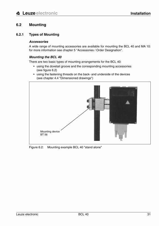
6.2.1 Types of Mounting
AccessoriesA wide range of mounting accessories are available for mounting the BCL 40 and MA 10:for more information see chapter 5 "Accessories / Order Designation".
Mounting the BCL 40There are two basic types of mounting arrangements for the BCL 40:
• using the dovetail groove and the corresponding mounting accessories (see figure 6.2)
• using the fastening threads on the back- and underside of the devices (see chapter 4.4 "Dimensioned drawings")
Figure 6.2: Mounting example BCL 40 "stand alone"
Mounting device BT 56

Installation Leuze electronic
32 BCL 40 Leuze electronic
Mounting BCL 40 and MA 10You can fasten the scanner BCL 40 and connector unit MA 10 tightly together to form asingle compact unit.
� Plug the two devices together at the 15 pin Sub D connector.Be sure that there is no dirt in the area of the seal (this guarantees an IP 65 protection class). Insert the two M4 x 30 screws included with the connector unit MA 10 into the countersunk drill holes on the bottom side of the MA 10, screw them into the correspond-ing threads in the BCL 40 and tighten them down.
There are three basic mounting arrangements for the BCL 40 / MA 10 unit:
• using the dovetail groove of the BCL 40 or the MA 10 and the corresponding mount-ing accessories
• using the two upper fastening threads on the rear of the BCL 40• using the four fastening threads on the underside of the MA 10 (see chapter 4.4
"Dimensioned drawings")
Notice!
The cable screw glands of the MA 10 can be set either on the right or the left side of the unit.Loosen the four Phillips screws on the back side of the MA 10, carefully lift off the cover, re-place it into the desired position and tighten down the four screws again. Be careful not todamage the ribbon cable.
Figure 6.3: Mounting example for the combined BCL 40 / MA 10 unit

Leuze electronic Installation
Leuze electronic BCL 40 33
TN
T 3
5/7-
24V
Independent mounting BCL 40 / MA 10Independent mounting of the BCL 40 and MA 10 is necessary when
• the available mounting depth is not sufficient for both devices, e.g. is less than 85 mm,
• or access to the mounting location of the scanner is difficult, but easy installation, commissioning and service are required, or
• the operating status LEDs on the back side of the MA 10 must be easily seen.
Figure 6.4: Mounting examples for the BCL 40 and MA 10 mounted independently
You can mount the individual devices in the following way as already described above:
• using the dovetail groove of the BCL 40 or the MA 10 and the corresponding mount-ing accessories
• using the fastening threads on the back- or underside of the devices• the connector unit can additionally be mounted using two M5 screws into the
threaded holes that are otherwise used for fastening the BCL 40. The threaded holes have M5 threads.

Installation Leuze electronic
34 BCL 40 Leuze electronic
6.2.2 Device Arrangement
Selecting a mounting locationIn order to select the right mounting location, several factors must be considered:
• size, orientation, and position tolerance of the bar codes on the objects to be scanned• the reading field of the BCL 40 in relation to the bar-code module width• the resulting minimum and maximum reading distance from the respective reading
field
For specific information, please refer to chapter "Optical Data" on page 20.
Notice!
The best reading results are obtained when
• the bar code is moved in a plane that is parallel to the reading window• the reading distance lies in the middle area of the reading field• high gloss labels or labels made from thermopaper are not used.
The minimum reading distance of a bar code scanner is often decisive when using label orpackaging machines due to the proximity of the scanner and labels.
Zero-distance scannerThe BCL 40 M 100 is a "zero-distance" scanner, i.e. it already has a reading field width of70 mm at a reading distance of 10 mm (module = 0.5). Labels are also read directly at thescanner window. In practice, however, this can lead to scratching of the scanner window andshould be avoided.
Notice!
On the BCL 40, the beam is not emitted perpendicular to the cover of the housing, but withan angle of 10° towards the top. This angle is intended in order to avoid a total reflection ofthe laser in the case of glossy labels. For highly reflective surfaces, this angle may bewidened by tilting the BCL.

Leuze electronic Installation
Leuze electronic BCL 40 35
TN
T 3
5/7-
24V
Figure 6.5: Minimum space requirements for installation
Mounting location
� When selecting a mounting location, pay attention to
• maintaining the required environmental conditions (humidity, temperature), • possible soiling of the reading window due to liquids, abrasion by boxes, or packaging
material residues,• lowest possible chance of damage to the scanner by mechanical collision or jammed
parts.
10˚ 10˚
10 1043
120
84
151
BCL 40 BCL 40 to MA 10
Width: 115 + cable outletWidth: 90

Installation Leuze electronic
36 BCL 40 Leuze electronic
Application example
Figure 6.6: Application example "conveyor chain"
With its high scan rate of 1200 scans/s, the BCL 40 is particularly well suited for use withhigh-speed conveyor belts.
Optical sensor
BCL 40
Connection cable BCL 40 / MA 10
Connection cable MA 10 / opt. sensor
Voltage supply
MA 10
Host interface

Leuze electronic Installation
Leuze electronic BCL 40 37
TN
T 3
5/7-
24V
6.3 Connection
Attention!
Never open the device yourself, as this may compromise protection class IP 65.
Before connecting the device, be sure that the supply voltage agrees with the value printedon the nameplate.
Connection of the device and maintenance work while under voltage must only be carriedout by a qualified electrician.
The power supply unit used to power the BCL 40 and MA 10 must have protected electricalseparation by way of a safety transformer with double insulation according to DIN VDE 0551(IEC 742).
Be sure that the earthing conductor is connected correctly. Error-free operation is only guar-anteed when the device is properly earthed.
If faults cannot be corrected, the device should be removed from operation and protectedagainst possible use.

Installation Leuze electronic
38 BCL 40 Leuze electronic
6.3.1 Connecting the BCL 40 for "Stand Alone" Operation
If you would like to connect the BCL 40 for "stand alone" operation, you must make a corre-sponding connector cable with a 15 pin Sub D plug (female) for the following connections:
• power supply of 18 … 36VDC, 5W max. power• host RS 232 interface, or RS 485 when operating as a "multiNet slave"• a sensor connection for triggering a read process
Figure 6.7: Connecting the BCL 40 for "Stand Alone" Operation
Attention!
When using a normal 15 pin Sub D plug, the device only has a protection class of IP 54 in-stead of IP 65!Therefore, use the original Leuze cable from the accessories list. These cables are fittedwith a seal so that protection class IP 65 is maintained.
Switching inputsA read process can be triggered by applying a voltage of 12 … 36VDC to the switched inputconnections "Sensor 1A" and "Sensor 1B". The switched input maintains an electrical sepa-ration of up to max. 250V.
15 pin Sub D female connector
Voltage supply 18 … 36VDC
InterfaceHost RS 485 /RS 232
RS 232 Terminal interface for com-missioning and service
Sensor connection(photoelec. sen-sor, key) for trig-gering a read process

Leuze electronic Installation
Leuze electronic BCL 40 39
TN
T 3
5/7-
24V
BCL 40 Sub D pin assignments
Figure 6.8: Connection diagram for the Sub D connector plug
4
15 pin Sub D typeconnector (male)
Insert a resistor R = 220 � / 0.25W here, if the de-vice is the last subscriber on the RS 485 data line. Do not use a resistor, if the RS 485 line continues.
Operating mode
1 GND 9 Sensor 1B2 Sensor 1A 10 NC3 CTS (Host) 11 RXD (Host)4 RTS (Host) 12 TXD (Host)5 TXT Service 13 RXD Service6 MODE-F 14 MODE-S7 reserved 15 GND_IN8 V_IN

Installation Leuze electronic
40 BCL 40 Leuze electronic
Wiring description
Table 6.1: Wiring description BCL 40
6.3.2 Connecting the BCL 40 with the connector unit MA 10
Connection of the BCL 40 is considerably easier when using the MA 10.
Figure 6.9: Connecting the BCL 40 with the connector unit MA 10
Pin 1 GND 0V signal reference potential (RS 232 / RS 485)
Pin 2 Sensor 1Aswitched input 1A, 12 … 36VDC,
see figure 6.18 and figure 6.19 for wiring
Pin 3 CTS (Host) CTS signal, host interface RS 232 / RS 485 B
Pin 4 RTS (Host) RTS signal, host interface RS 232 / RS 485 B
Pin 5 TXD Serviceused when MA 10 is connected /
without MA 10: service interface, standard protocol
Pin 6 MODE_F RS 232: open; RS 485: connect with MODE_S
Pin 7 reserved must not be used
Pin 8 V_IN supply voltage +18 … 36VDC
Pin 9 Sensor 1Bswitched input 1B, 12 … 36VDC,
see figure 6.18 and figure 6.19 for wiring
Pin 10 NC not used
Pin 11 RXD (Host) RXD signal, host interface RS 232 / RS 485 A
Pin 12 TXD (Host) TXD signal, host interface RS 232 / RS 485 A
Pin 13 RXDservice used when MA 10 is connected /
without MA 10: service interface, standard protocol
Pin 14 MODE_S RS 232: open; RS 485: connect with MODE_F
Pin 15 GND_IN supply voltage 0VDC
Power supply
Sensor, Button
Connection cableBCL 40 / MA 10
Switching output
host interfaceRS 232, RS485, RS422 or TTY

Leuze electronic Installation
Leuze electronic BCL 40 41
TN
T 3
5/7-
24V
Open the MA 10 housing
� Loosen the four Phillips screws on the back side of the MA 10 and carefully lift off the part with the electronics on it.
The two halves of the housing are now connected to each other only by the ribbon cable.
You can now disconnect the ribbon cable from the electronic circuit board for
better access, as shown in figure 6.10.
Figure 6.10: Disconnecting the ribbon cable inside the MA 10
� To disconnect the ribbon cable, carefully press down the two latches of the ribbon cable plug at the same time, as shown in figure 6.10 of �.
The cable is now free (� in figure 6.10) and the half with the electronics and the connectionterminal can be removed for unhindered connection.
� To reconnect the ribbon cable, insert the ribbon cable plug back into its socket, observing the correct orientation, until it securely latches.
Notice!
All electrical connections can be carried out on the terminal strip quickly and without screw-ing down or soldering. Wires with ferruled ends can be inserted directly into the terminalwithout depressing the clamping lever.

Installation Leuze electronic
42 BCL 40 Leuze electronic
Figure 6.11: Wiring to the terminal strip without screwing down or soldering
Attention
The pin assignment of the connection terminals depends on the inserted interface module.Leuze offers four modules which can be used with the serial interfaces RS 485, RS 232,TTY or RS 422. The terminal designations are printed on the module.
Figure 6.12: Position of the connections for the MA 10
The clamp is opened by depressing the orange coloured clamping lever.
The wire can then be inserted into the terminal.
By releasing the clamping lever, the wire is fixed into the terminal.
Attached label with the pin assignments of the interface
Terminal strip
Attached label with the terminal names
Cable screw glands PG9 and PG11

Leuze electronic Installation
Leuze electronic BCL 40 43
TN
T 3
5/7-
24V
Type overviewThe following table lists the MA 10 device types and which interface is installed.
� Make the connections to the terminal strip as described below.
Wiring descriptionTerminals 1 through 6 are used depending on the type of interface:
MA 10 100 RS 485 interface
MA 10 110 RS 232 interface
MA 10 120 TTY interface
MA 10 130 RS 422 interface
RS 232 RS 422
Terminal Signal Terminal Signal
1 RXD 1 TX+
2 TXD 2 TX-
3 CTS 3 RX+
4 RTS 4 RX-
5 not used 5 not used
6 GND 6 GND
RS 485 TTY
Terminal Signal Terminal Signal
1 485A 1 TX+
2 485A 2 TX-
3 485B 3 RX+
4 485B 4 RX-
5 GND 5 not used
6 GND 6 GND

Installation Leuze electronic
44 BCL 40 Leuze electronic
RS 485 interface
Figure 6.13: Connecting the MA 10 to a RS 485 Host
RS 232 interface
Figure 6.14: Connecting the MA 10 to a RS 232 Host
Notice for connecting the RS 232 interface:
The wiring for RTS and CTS must only be connected, if RTS/CTS hardware-handshake isused.
RS485
485A 1485A 2485B 3485B 4G N D 5G N D 6
12
34
56
4 85A
485B
GN D
485A
485B
GND
Host
Shield
Host interface module
up to 1200m
Shield
12
34
56
RS232
R XD 1TX D 2C TS 3R TS 4- 5G N D 6
RXDTXDCT SRTS GND
Host
Shield
Host interface module
up to 10m

Leuze electronic Installation
Leuze electronic BCL 40 45
TN
T 3
5/7-
24V
TTY interfaceMA 10 active / Host passive
Figure 6.15: Connecting the MA 10 as active subscriber to a TTY Host
MA 10 passive / Host active
Figure 6.16: Connecting the MA 10 as passive subscriber to a TTY Host
Hints for connecting the TTY interface:
The active subscriber is the one which supplies the current (20mA).
Switching between active/passive on the host interface card is carried out using two jumperpairs, independent for transmit (Tx) and for receive (Rx).
Shield
Shield
Jumper position active
Ground(shield)
Host interface module
up to 1000m
Shield
Shield
Jumper position passive
Jumper
Jumper
Host interface module
Ground(shield)
up to 1000m

Installation Leuze electronic
46 BCL 40 Leuze electronic
The jumpers for active/passive switching must always be changed in pairs (upper and lowerjumpers in the same position). This switches the MA 10 host interface module power sourceand GND internally.
Mixed operation is possible (transmit active/receive passive or the opposite).
When switching from active to passive operation or the reverse, the wiring of the connectioncable (pin order) changes.
RS 422 Interface
Figure 6.17: Connecting the MA 10 to a RS 422 Host
The additional pins are uniformly assigned for all MA 10 models and are described below.
Switching inputs 1 and 2 Switching inputs
The MA 10 has two galvanically isolated switching inputs SE1 and SE2.
• Input voltage: 12 … 36VDC/AC.• Insulation voltage: 500V
Each switching input is supplied with bi-directional optical couplers and protective resistors.
The switching voltage and GND can be externally applied or taken from the operatingvoltage VDD_SE and GND_SE.
12
34
56
RS422
TX + 1TX - 2RX+ 3RX- 4- 5G N D 6
Rx+Rx-Tx+Tx-
GND
Host
Shield
Host interface module
up to 1200m

Leuze electronic Installation
Leuze electronic BCL 40 47
TN
T 3
5/7-
24VFigure 6.18: Connection of the switching input with an external switching voltage
Figure 6.19: Connection of the switching input without an external switching voltage
Terminal Signal Function
7 SE2_A switching input 2, connection A
8 SE2_B switching input 2, connection B
9 SE1_A switching input 1, connection A
10 SE1_B switching input 1, connection B
11 VDD_SEsupply voltage, switching input,
equal to V_IN device
12 GND_SEsupply voltage, switching input,
equal to GND_IN device
MA 10
Supply voltageMA 10 / BCL 40: 18 … 36V
Optically coupled switched input
to processor
Externalswitching voltage
MA 10
Supply voltageMA 10 / BCL 40: 18 … 36V
Optically coupled switched input
to processor
Sen
sor/
optic
al s
enso
r

Installation Leuze electronic
48 BCL 40 Leuze electronic
Switching outputs 1 and 2 Switching outputs
The MA 10 comes standard with two switching outputs (SA1 and SA2) that can beprogrammed for various switching functions using the BCL software.
• Output voltage: 5 … 48VDC• Insulation voltage: 250V (only in combination with connection type b))• Output current: Imax = 500mA (at VDD_SA = 5 … 32V)
Imax = 300mA (at VDD_SA = 32 … 48V)
The switching voltage can be connected in two different ways:
• The operating voltage V_IN is used as the switching voltage VDD_SA (factory setting):VDD_SA = V_INGND_SA = GND_IN
• An external voltage is connected as switching voltage (galv. decoupled)VDD_SA V_INGND_SA GND_IN
Figure 6.20: Position of the solder jumpers JL5 and JL6
Terminal Signal Function
13 SA2 Switching output 2
14 SA1 Switch 1
15 VDD_SAexternal voltage supply for switched output
5 … 48VDC
16 GND_SA external voltage supply for switched output 0VDC
13 14 15 16
JL5JL6
GN
D_S
A
VD
D_S
A
SA
1S
A2
Galvanic decoupling of the switched outputGalvanic decoupling is achieved by carefully scratching through the two solder jumpers JL5 and JL6 so that there is no longer an electrical connec-tion. The switched output is then galvanically de-coupled from the operating voltage.The solder jumpers are located on the circuit board of the MA 10 directly across from the connection terminals VDD_SA and GND_SA.
Scratch through here
Scratchthrough
here
Switching outputs

Leuze electronic Installation
Leuze electronic BCL 40 49
TN
T 3
5/7-
24V
Figure 6.21: Operating voltage used as the switching voltage
Figure 6.22: Switching voltage connected externally (galvanically decoupled)
Controlling the function of the switching outputsThe function of the switching outputs can be controlled by removing the cover to the MA 10.Sitting directly next to the connection terminals for the switching outputs are red SMD-LEDsthat illuminate when the respective switching output is in the HI state (log.1). Please notethat the event which sets the switching outputs must be set and activated in the softwaresetup of the BCL 40.
R L
VDD_SA
SA1/2
GND_SA
JL6
JL5
V_IN
GND_INMA 10
Optically coupled switched input
from processor
solder jumper
solder jumper
VDD_SA
SA1/2
GND_SA
JL6
JL5
V_IN
GND_IN
MA 10
R L
U
Optically coupled switched input
from processor
solder jumper open
solder jumper open

Installation Leuze electronic
50 BCL 40 Leuze electronic
Supply voltage
6.3.3 Wire Lengths and Shielding
The following maximum lengths for wires and the type of shielding to be used must beobserved:
6.4 Disassembling, Packing, Disposing
RepackingFor later re-use, the device is to be packed so that it is protected against shocks and damp-ness. Optimal protection is achieved when using the original packaging.
Notice!
Electrical scrap is a special waste product!Observe the locally applicable regulations regard-ing disposal of the product.
Terminal Signal Function
17 V_IN Operating voltage +18 … 36VDC
18 V_IN Operating voltage +18 … 36VDC
19 GND_IN Operating voltage 0VDC
20 GND_IN Operating voltage 0VDC
21 PE Protective earth, grounding
22 PE Protective earth, grounding
Connection Interface Max. wire length
Shielding
BCL 40 - MA 10 RS 232 / RS 485 10m absolutely required, shield meshing
BCL 40 - Host RS 232 / RS 485 10m absolutely required, shield meshing
MA 10 - Host RS 485 1200mabsolutely required,
flexible leads as twisted pairs
MA 10 - Host RS 422 1200mabsolutely required,
flexible leads as twisted pairs
MA 10 - Host RS 232 10mabsolutely required,
flexible leads as twisted pairs
MA 10 - Host TTY 1000mnot required
loop resistance < 100
Switching inputs 10m not necessary
Switching outputs
10m not necessary
Table 6.2: Wire Lengths and Shielding

Leuze electronic Commissioning
Leuze electronic BCL 40 51
TN
T 3
5/7-
24V
7 Commissioning
7.1 Measures to be performed prior to the first commissioning� Before commissioning, familiarise yourself with the operation and configuration of the
device(s)!
� Before switching on, recheck all connections and ensure that they have been properly made.
Figure 7.1: Control elements of the MA 10
Reset button:- Press < 4s:
"warm start"- Press > 4s:
"cold start"
DIP-switch 1 "ParaDefault":ON on reset (’cold start’) fac-
tory setting parameter set is loaded
OFF on reset (’cold start’) cus-tomer-specific parameter set is loaded
DIP switch 2 "autoConfig" and parallel connected jump-er:ON "autoConfig" function
activatedOFF "autoConfig" function
deactivated
Data logging jumper for the interface terminal- Jumper above: Data from Host - Jumper below*: Data from BCL
Jumper for setting the device address range:- Right jumper Addr. 0 … 15- Left jumper Addr. 16 … 31
Coding switch 0 … F for setting the device address:The switch positions 0 … F correspond to the device ad-dress 0 … 15 or 16 … 31.
Interface terminal RS 232 for commis-sioning and service
Operating modes switch:Switch setting 1:SERVICE*Switch setting 2:OPERATION
*In service operation, the jumper must be in the "lower" position. Communication is otherwise not possible.

Commissioning Leuze electronic
52 BCL 40 Leuze electronic
Setting the device address
The device address is set in the MA 10 using a rotary code switch.
� Set the device address on the code switch to:
• 0, if the combined BCL 40 / MA 10 unit will not be operated in a network,
• 1 … 31, if several BCL 40 / MA 10 units will be operated in a network. Each multiNet plus network device must have a different device address assigned to it.If the RS 485 module is plugged in and connected to the mulitNet master, the BCL 40 / MA 10 automatically becomes a multiNet plus slave device.
Reset
Both devices can be reset using the reset button in the MA 10:
"Warm start"
If the reset button in the MA 10 is pressed for a short time (0.2 to 4 sec.), a so-called "warmstart" will be carried out. This will reinitialise both devices and load the current parameter setinto memory from the EEPROM.
"Cold start"
If the reset button in the MA 10 is pressed until all four LEDs on the back of the device illu-minate (longer than 4 seconds), a so-called "cold start" will be carried out. This will reini-tialise both devices and, depending on the DIP switch setting "ParaDefault", will either loadthe customer-specific parameter set or the factory default parameter set into memory.
DIP switch setting 1 "ParaDefault":
OFF - the customer-specific parameter set is loaded.ON - the factory default parameter set is loaded.
Notice!
The customer-specific parameter set is a backup copy of the current parameter set. It mustbe explicitly loaded using the command "PC01" after saving the BCL set-up and is only avail-able in the MA 10 (not the BCL 40).The customer-specific parameter set can then be loaded by executing a ’cold-start’.For spe-cific information, see chapter 9.3.5 ""Online" Commands for Parameter Set Operations".
� Set DIP switch 1 corresponding to the parameter set that should be loaded after a "cold start" has been initiated.
After resetting the device, all four LEDs on the back side of the MA 10 illuminate for approx.1/2 second. During software initialisation, the green "RDY" (ready) LED blinks.
If the green "RDY" LED continuously illuminates, the initialisation is complete and the deviceis ready for operation.

Leuze electronic Commissioning
Leuze electronic BCL 40 53
TN
T 3
5/7-
24V
Notice!
If the BCL 40 is to be operated as a "stand alone" device, a reset is only possible via soft-ware. There is a small green LED inside the BCL 40 at the lower edge of the reading windowthat displays the operation readiness. The LED can also be used to monitor the operatingstatus of the BCL 40 in "stand alone" operation. During a reset, the LED remains dark andcontinuously illuminates when the device is ready for operation.
7.2 Function Test
"Power On" test
After connecting the operating voltage, the devices carry out an automatic "Power On" func-tion test. All four LEDs on the back of the MA 10 illuminate for approx. 1/2 second. Duringsoftware initialisation, the green "RDY" (ready) LED blinks.
Once the green "RDY" LED continuously illuminates, the device is ready for operation.
Interface
Proper function of the interface can be tested easiest in service operation using the serviceinterface with the "BCL Configuration Tool" software and a notebook computer.
"Online" commands
Using the "Online" commands, the important device functions can be checked, e.g. properfunctioning of the laser( see chapter 9 "Communicating with the Device").
Problems
Should problems occur during device commissioning, refer first to chapter 8.2. Should aproblem persist after checking all electrical connections and settings on the devices andhost, please contact a Leuze service office near you (see the back page of this operatingmanual).
7.3 Setting the Parameters
You have now commissioned the BCL. Usually, you will have to configure it before you canuse it. Using the parameter options made available by the BCL, you may configure the BCLto suit your individual area of application. For instructions regarding the various settingoptions refer to chapter 9 or to the online help of the configuration software "BCL Configu-ration Tool".
In order to operate the BCL, it is typically sufficient to set code type and code length inaccordance with the bar codes that are to be read. However, depending on the application,you will configure the switching inputs and outputs according to your requirements.
The setting of code type and code length is usually accomplished by using the program "BCLConfiguration Tool", see chapter 9.2 "Graphic configuration using the "BCL ConfigurationTool" software".

Commissioning Leuze electronic
54 BCL 40 Leuze electronic
To understand what is happening during the parameter setting, the chapter 7.3.1 brieflyexplains the various parameter sets.
The setting of the parameter sets then takes place in the operating mode "service", which isdescribed in chapter 7.3.2.
7.3.1 Parameter sets
Three different parameter sets are maintained by the MA 10 when using the BCL 40 / MA 10combined unit:
• the factory default parameter set• the customer-specific parameter set• the current parameter set
Before a parameter set is loaded into the BCL 40 processor memory, the validity of theparameter set is checked using checksums.
Factory default parameter setThis parameter set contains the default settings made ex works for all BCL 40 parameters.It is permanently stored in the ROM of the BCL 40. The parameter set with the defaultsettings is loaded into the memory of the BCL 40,
• the first time the device is commissioned after delivery• after a "cold start" reset ("ParaDefault" switch ON)• if the check sums of the current and the customer-specific parameter set are invalid.
Customer-specific parameter setIn this parameter set, customer-specific settings for all device parameters can be stored.There are two ways to store the parameter set in the EEPROM of the MA 10:
• by copying a valid parameter set, i.e. an already stored and tested 'current parameter set' from the EEPROM of the MA 10.
• by copying (parameter "Download") a valid parameter set from the host computer (e.g. a PC or PLC).
The customer-specific parameter set is copied into the current parameter set:
• after a "cold start" reset ("ParaDefault" switch OFF)• if the checksum of the current parameter set is invalid

Leuze electronic Commissioning
Leuze electronic BCL 40 55
TN
T 3
5/7-
24V
Current parameter setIn this parameter set, the current settings for all device parameters are stored. If the BCL 40is in "stand alone" operation, the parameter set is stored in the EEPROM of the BCL 40. Ifan MA 10 is also used, the parameter set is stored in EEPROM of the MA 10 and a copythereof in the EEPROM of the BCL 40. The current parameter set can be stored in threeways:
• by changing and storing the current parameter set using the integrated SETUP pro-gram of the BCL 40
• by copying (parameter "Download") a valid parameter set from the host computer (e.g. a PC or PLC).
• by means of an off-line setup with the program "BCL Configuration Tool"
The current parameter set is loaded into the memory of the BCL 40:
• each time the supply voltage is connected• after a "warm start" reset, as well as a software reset
Figure 7.2: Block diagram storage concept for parameter sets
Notice!
By storing all current and customer-specific values in the connector unit MA 10, a connectedBCL 40 can be exchanged without difficulty since all parameters are maintained.
ROMDefault PS (2)
EEPROMCurrent PS (0)
RAMWorking copy of current PS
ROMDefault PS (2)
EEPROMCurrent PS (0)
RAMWorking copy of current PS
ROMCustomer-
specific Parameter set (1)
EEPROMCurrent
parameter set (0)
MA 10
BCL 40
BCL 40
Terminal program on PC
Parameter "Down-load" from HOST
Parameter "Download" from HOST
Terminal program on PC
BCL 40with MA 10
BCL 40 "Stand alone"
"2" = parameter set with factory default settings"1" = customer-specific parameter set"0" = current parameter set

Commissioning Leuze electronic
56 BCL 40 Leuze electronic
7.3.2 Service Operating Mode
Setting the required parameters is carried out easiest in the "service" operating mode.
Interface terminal
By switching the operating mode switch from operation (setting 2) to service (setting 1), theconnection to the host computer is broken and the RS 232 service interface is activated.
The MA 10 offers a service interface for commissioning the read station in a network. Theinterface consists of a 9 pin SubD connector (male) and can be reached by removing thehousing cover on the MA 10.
Connection
A PC or terminal can be connected to the MA 10 via the RS 232/V.24 serial interface andused to set the parameters of the BCL 40. The connection is made using a crossed RS 232connection cable that establishes the RxD, TxD and GND connections. A hardware hand-shake via RTS, CTS is not supported at the service interface.
Figure 7.3: Connecting the service interface to a PC or terminal
For specific information, see figure 7.1 "Control elements of the MA 10" on page 51.
Communication to the host computer via the host interface is no longer possible. Switchingto service mode results in a pre-set transfer protocol with the following parameters:
• transfer rate 9600baud
• no parity
• 8 data bits
• 1 stop bit
• prefix: STX
• postfix: CR, LF
Construction of the data frame at the service interface
Prefix 1 Data Terminator 1 Terminator 2
ASCII STX e.g.: "CODE" CR LF
HEX 02h 43h 4Fh 44h 45h 0Dh 0Ah
PC/terminalCOM interface
MA 10 service interface

Leuze electronic Commissioning
Leuze electronic BCL 40 57
TN
T 3
5/7-
24V
Wiring descriptionThe 9 pin Sub D RS 232 Terminal connector (male) has the following pin assignments:
Using a PC and a terminal program, the set-up program of the BCL 40 can be called, onlinecommands sent and data received via this interface terminal.
Notice!
In setting 2 ("operation") of the operating mode switch, the terminal connector can be usedas a data monitor. In this case, data sent from the BCL 40 (jumper in figure 7.1 in lower po-sition) or data received from host (jumper in figure 7.1 in upper position) can be logged. Thedata protocol is set by the host interface in the latter case.
Configuration softwareLeuze offers a convenient program "BCL Configuration Tool" for setting the required deviceparameters (see chapter 5 "Accessories / Order Designation").
7.3.3 Setting Parameters "Offline"
Setting parametersThe parameters are programmed on a PC without direct connection to the BCL 40 ("Offline"programming) and saved in a file (parameter file).
Downloading parametersAfter successful programming, the parameters are loaded into the BCL 40 (parameter"Download"). This causes the required parameters to be transferred from the host computer,or a computer connected to the interface terminal of the MA 10, to the BCL 40 or MA 10,respectively.
Pin 1 NC not used
Pin 2 RXD receive signal of the RS 232 service interface
Pin 3 TXD transmit signal of the RS 232 service interface
Pin 4 NC not used
Pin 5 GND signal reference potential 0VDC
Pin 6 RXD_Host receive signal of the host interface
Pin 7 NC not used
Pin 8 NC not used
Pin 9 reserved for service purposes only

Commissioning Leuze electronic
58 BCL 40 Leuze electronic
7.3.4 Setting Parameters "Online"
The other possibility for setting the required operating parameters of the BCL 40 is through"Online" programming via the integrated, two-language set-up program (English, German)in the BCL 40.
Setup program
Using a PC (notebook) connected to the interface terminal, the menu-driven set-up programcan be called while in the service operating mode.
"Online" commands can then be directly entered that query data or carry out a softwarereset.
Communication is carried out using a terminal program or more conveniently using theLeuze configuration program.
A detailed description of the setup program along with all parameters which can be set, aswell as the most important "Online" commands can be found in chapter 9.
7.3.5 Setting the Bar Code Parameters Using "autoConfig"
The parameters of the bar codes which are to be read can be easily set using the function"autoConfig".
In order to check the programmed bar codes, the BCL 40 should be connected to a dataterminal. The detection of the desired bar code(s) can be checked on the terminal.
Manual or "Online" activation
• The "autoConfig" function is activated on the MA 10 using DIP switch 2 (see figure 7.1 for the location of the DIP switch).
• The "autoConfig" function can be activated and deactivated via the serial interface (host or service interface) using the "Online" commands 'CA+' (activate) and 'CA-' (deactivate).
Details of "Online" commands can be found in chapter 9.
If "autoConfig" is active, the ERR LED and RDY LED on the MA 10 alternately blink.
Setting parameters
After activating the "autoConfig" function, the BCL 40 can read from one to eight examplelabels containing the bar codes which are to be read. The BCL 40 decodes the labels anddisplays, via the interface, the code type, the number of decoded characters and the char-acter itself.
Number of labels to be decoded
While "autoConfig" is active, have the BCL 40 read as many labels in row as it will laterduring a reading cycle when in normal operation. The number of labels can be set from "SetCode" in the submenu "Decoding" of the setup program. The number of labels is limited to8 when using the "autoConfig" program.
Leuze electronic Commissioning
Leuze electronic BCL 40 59
TN
T 3
5/7-
24V
Code type and No. of characters of the label to be decodedThe BCL 40 evaluates the number of labels, and at the same time, the code type andnumber of characters. This corresponds to the programming of the code types in thesubmenu "Decoding / Select Code Type" of the setup program.
Normal state of the MA 10 switched input SE1The state (high or low) which is present at the switched input SE1 while the "autoConfig"function is active is taken as the new normal state for this switched input. This correspondsto the function "Inversion" in the submenu "Switched Inputs and Outputs / Switched InputDecoding (S1)" of the Setup program.
Store parametersWhen the "autoConfig" program is deactivated, the programmed parameters are stored andcopied into the current parameter set.
Before deactivating the "autoConfig" function, please remove any labels from the scanningarea of the BCL 40 since the new code parameters otherwise will not be stored properly.

Operation Leuze electronic
60 BCL 40 Leuze electronic
8 Operation
8.1 Display ElementsOn the back side of the MA 10, there are 4 LEDs which display the momentary operatingstatus.
Status conditions of the LEDs
LED Colour Meaning
RDY green Ready
ERR yellow Error
ACT red Scanner active
DEC green Decoding successful
All four LEDs illuminate• for approx. 0.5 second after connecting the operating voltage.• after accepting a "cold start" reset (> 4s) up until the reset button is released.
All four LEDs blink• if the connection between the MA 10 and BCL 40 is interrupted.
RDY blinks• during the "Power On" function test.
RDY illuminates• when the devices are ready.
ERR illuminates• if a hardware error is encountered after the initialisation phase or in the case of a
serious software error.
RDY and ERR blink simultaneously• when the setup program is activated.
Notice: No read operations can be carried out.
RDY and ERR blink alternately• when the "autoConfig" function is activated by setting the corresponding
DIP switch.• when a reference code is defined (Teach-In).ACT illuminates• while the scanner is active, i.e. when the laser is in operation.
ACT blinks• if a warning is output during the 'autoControl' function.
DEC illuminates• for approx. 0.5 second after successfully completing a decoding process.

Leuze electronic Operation
Leuze electronic BCL 40 61
TN
T 3
5/7-
24V
8.2 Important Functions During Operation
The BCL 40 has a function which automatically monitors the reading quality as well as thequality of the bar code label.
"autoControl" function
When the "autoControl" function is active, the BCL 40 constantly compares the total numberof scans with the number of decoded scans. If the number of decodable scans falls below auser defined percent of the total scans, the MA 10 outputs a warning:
• the ACT LED blinks.
• a warning symbol can be output to the host.
• a switched output can be controlled.
A detailed description of all adjustable parameters can be found in chapter 9.
8.3 Error Handling
Errors are visibly indicated on the MA 10 via the ERR LED (see chapter 7.2 "Function Test").
Further error, warning and status messages are transferred via the host interface or theterminal interface.
Types of errors
Errors are divided up into the following types:
• Warnings
• Serious errors
Warnings
Warnings indicate temporary operating faults which do not effect the proper functioning ofthe device.
Serious errors
Serious errors impair the proper functioning of the device. The device must be reinitialised.
Troubleshooting
Isolated warnings can be ignored, since the BCL 40 will continue to function properly.
Following a serious error, you should reinitialise the BCL. It will then usually again functionproperly. If a hardware problem is present, the BCL 40 will not reinitialise.
Warnings and errors which occur frequently can be corrected easiest using the "BCL Config-uration Tool" configuration and control software.
If you cannot correct faults and errors with the software, please contact a Leuze electronicsales office or service facility. For addresses, please refer to the back page of this operatingmanual.

Communicating with the Device Leuze electronic
62 BCL 40 Leuze electronic
9 Communicating with the DeviceDevice parameters can be set via commands or using the easy-to-use "BCL ConfigurationTool" control software.
9.1 Installation of the "BCL Configuration Tool" software� Place the installation CD in your CD drive.
� Call up the installation file (e.g. Setup.exe)
The following window appears:
Installation window
Figure 9.1: Installation window
� Confirm the following licence agreement and select the installation path in the following window:

Leuze electronic Communicating with the Device
Leuze electronic BCL 40 63
TN
T 3
5/7-
24V
Installation directory
Figure 9.2: Installation directory
� Confirm your entry with Continue, then follow the installation routine.
For further details please refer to online help of the "BCL Configuration Tool" software.
9.2 Graphic configuration using the "BCL Configuration Tool" softwareIn the following, you will find an overview and brief explanation of the adjustment optionsoffered on the individual tabs.

Communicating with the Device Leuze electronic
64 BCL 40 Leuze electronic
9.2.1 Code menu
Figure 9.3: "Decode" menu, standard setting
Option Explanation
Code table
Here, the codes which are to be decoded are set.As of software version V51.03 of BCL 40, the codes depicted above are enabled by default. We recommend enabling only the code types which are to actually be read with the corresponding element numbers.Notice: Code1 must always be selected. If multiple code types are to be used, set in sequential order: Code1, Code2…
Element number
In the field Element number, up to 3 element entries may be entered.An area is represented by a dashed line: e.g. 4-40 digits.With 2 or 3 different element entries by a comma: e.g: 8,13 digitsBoth are possible as well: e.g.: 4-10,20 digitsNotice: If the code EAN128 is to be read, 3 additional digits are to be set for the code identifier.
PropertiesBehind the "Properties" button, to the right of the respective code, thecode-specific settings, such as the check digit, can be selected.
Number of bar codes
Here, the number of the bar codes to be decoded within a read cycle(one reading gate) is set.

Leuze electronic Communicating with the Device
Leuze electronic BCL 40 65
TN
T 3
5/7-
24V
Attention!
Due to its internal design (hardware-ASIC-decoding), only one double-width code may beenabled for the BCL40. Double-width codes are the codes Code 2/5 Interleaved, Code 39 and Codabar. This means that only one of these three code types may be enabled!
Properties of the Code menu
Figure 9.4: Properties of the Decode menu, standard setting
Option Explanation
Min wide narrow ratio
This value may be changed only in special cases!
Quiet zone size
Quiet zone: the area to the left and right of the bar codeModule: width of the narrowest line in the bar codeAccording to the code specifications, each bar code must have a quiet zone which is 10x as wide as the module of the bar code. Ex: for a code having a module of 0.5mm, 5mm blank space must be present at both the left and right of the code. By default, the scanner checks the a quiet zone which is 7 times greater than the module. This means that 7x or greater is o.k.
Scans between info
Number of scans which return no decodable data for a given label which must be performed before further data are classified as belong-ing to a different label. In this way it is possible to differentiate between sequential labels with identical data. This setting does not need to be changed in normal use.
Reading security (equal scans)
Specifies how often a code must be decoded before the result is valid and output. This value can be increased for inspection and test purposes.

Communicating with the Device Leuze electronic
66 BCL 40 Leuze electronic
9.2.2 Output menu
Figure 9.5: "Output" menu
Option Explanation
Output headerSelect from the options listed below. The output header is sent in a separate message before the read result.
Label header The Label header is set directly before the code data.
Label footer The label footer is appended directly to the code data.
All labels in one message
If this item is activated, all read codes are sent together with the output header in a complete message.-> The structure of this message string is depicted symbolically in the preview window.
No read stringThis character is set for each unrecognised bar code. Multiple charac-ters (= string) may be entered here. Up to 20 characters are possible.
PropertiesSet the desired formatting modes and formatting characters as necessary.

Leuze electronic Communicating with the Device
Leuze electronic BCL 40 67
TN
T 3
5/7-
24V
9.2.3 Control
Figure 9.6: "Control" menu, standard setting
Option Explanation
Activation
Sensor 1If this item is selected, the scanner can be activated via its switching input 1 (= trigger start reading gate).
Command characters
The standard online character for the trigger start is the "+" charac-ter. This character can be changed only via the tree structure.
Decode delay time
This point is usually used only for test purposes. After the time set here has passed, the scanner automatically reactivates itself follow-ing a reading gate end.
Deactivation
Sensor 1 This item changes together with switching input 1 upon "Activation".
Command characters
The standard online character for the trigger end is the "-" character. This character can be changed only via the tree structure.

Communicating with the Device Leuze electronic
68 BCL 40 Leuze electronic
9.2.4 Communication
Figure 9.7: "Communication" menu, standard setting
Select the desired baud rate, the stop bits, the data bits and the parity here. In addition,several different handshake modes and protocols can be set here.
The RK512/3964 protocol can also be selected here. The individual parameters for thisprotocol can be found in the tree-structure configuration and Communication -> CustomerInterface -> 3964 / RK 512 Protocol.
Attention!
If the BCL 40 is operated in a network ("Leuze multiNet"), no changes may be made here.The scanner automatically sets itself to the multiNet protocol!
After equal scans reach
If this item is activated, the read result is output immediately after the bar code is decoded. If the item is deactivated, the read result is sent only after the trigger signal is returned (= end of reading gate).
TimeFor test purposes.If the scanner is activated, the reading gate is automatically closed by the scanner after this preset time has elapsed.
Scans without infoFollowing a successful read, the scanner waits for this number of scans (sequential scans with no read result) before it automatically deactivates itself.
Option Explanation

Leuze electronic Communicating with the Device
Leuze electronic BCL 40 69
TN
T 3
5/7-
24V
Communication properties
Figure 9.8: Properties of the Communication menu, standard setting
Here, the frame format (prefix/postfix), the address mode as well as a BCC mode can be set.
Attention!
During Leuze multiNet operation, no changes may be made here!

Communicating with the Device Leuze electronic
70 BCL 40 Leuze electronic
9.2.5 Reference code
Figure 9.9: "Reference code" menu
A reference code is bar code information which is stored in the memory of the scanner. Thisreference code can be compared with the current decoded bar code in various modes and,thus, set appropriately for the switching output. To do this, the switching output must still beset to "By comparison of reference code X" in the "Switch" menu.
One way to store the reference code is to enter it manually in this menu. Other possibilitiesof the reference code teach-in see chapter 9.3.1 "General "Online" Commands" and chapter9.2.6.
Option Explanation
Type Select the code type.
Contents Contents of the reference code
Compare mode
Select here how the internally stored reference code is to be compared with the decoded result. For additional comparison possibilities, please select the "Properties" menu.

Leuze electronic Communicating with the Device
Leuze electronic BCL 40 71
TN
T 3
5/7-
24V
9.2.6 Sensor
Figure 9.10: "Sensor" menu, standard setting
Notice!
Sensor 1 must be used at the beginning of the reading gate (trigger).Sensor 2 can only be used for the reference code teach-in.
Notice!
If a BCL40 is operated without a MA10 or MA30 connector unit, only switching input 1 isavailable!
Option Explanation
Enabled Switching input enabled or disabled.
Invert Here, the input level can be inverted.
Debounce timeThis amount of time is allowed to pass before the signal is passed on internally for further processing.
Delay off timeThis parameter is used to extend the trigger signal internally by means of software.

Communicating with the Device Leuze electronic
72 BCL 40 Leuze electronic
9.2.7 Switching outputs
Figure 9.11: "Switch 1" menu, standard setting
Notice!
If a BCL 40 is operated without a MA10 or MA30 connector unit, no switching output isavailable!
Option Explanation
Enabled Switching output enabled or disabled.
Invert Invert the level.
ActivationSelect the desired event which is to initiate the switching of the switch-ing output here. Multiple events can also be simultaneously activated.
DeactivationShown here is the event which results in the switching output being reset (if the set pulse duration has not yet expired). These events are only displayed and cannot be changed directly.
Pulse duration Duration of the switching output impulse.
Pulse numberNumber of pulses.If the value here is set to 0, a continuous signal is applied to the switch-ing output which is not reset until the event on "deactivation".

Leuze electronic Communicating with the Device
Leuze electronic BCL 40 73
TN
T 3
5/7-
24V
9.3 Overview of Commands and ParametersOnline commands can be used to send commands directly to the device for control andconfiguration.
For this the BCL 40 / MA 10 must be connected to a host or service computer via the serialinterface. The commands described can be sent either via the host or the service interface.
For information on the transmission protocol, please see chapter 7.3.3.
Be sure that both data devices are set to the same protocol:
• service interface: 9600 Baud, 8-None-1
• host interface: protocol configured by user
"Online" commands
With the commands, you can
• call the setup program,
• carry out a software reset in order to reinitialise the device,
• call up error messages,
• call up statistical device information,
• internally copy and test parameter sets,
• activate and test system components,
• control/decode reading gate,
• read/write/copy parameters,
• carry out an automatic configuration,
• teach/set reference code.
Syntax
"Online" commands consist of one or two ASCII characters followed by commandparameters.
No separation characters may be entered between the command and the command param-eter(s). Both small and capitalised letters can be used.
Example:
Command ’CA’: "autoConfig" function
Parameter ’+’: Activation
Transmitted is: ’CA+’
Notation
Commands, command parameters and returned data are enclosed between single quota-tion marks ’ ’.
Most "online" commands are acknowledged by the BCL 40 and any requested datareturned. For commands that are not acknowledged, command execution can be observedor monitored directly on the device.

Communicating with the Device Leuze electronic
74 BCL 40 Leuze electronic
9.3.1 General "Online" Commands
Software version number
Notice!
Using this command, you can check whether the connected host or service computer isproperly connected and configured. If you do not receive an acknowledgement, pleasecheck interface connections, protocol and service switches.
Software reset
Command ’V’
Description Requests device version information
Parameter no
Acknowledge-ment
’BCL 40’’V 50.09’’22.06.97’’MA 10’ (only when a ’V 01.07’ MA 10 connector unit is installed)The device type appears in the first line followed by the software version number and date. The device type on the connector unit appears on the fourth line followed by the version number. The data which are actually displayed may vary from the values given here.
Command ’H’
DescriptionCarries out a software reset. The device is restarted and reinitialised, leav-ing it in the same state as when the supply voltage is switched on.
Parameter no
Acknowledge-ment
’S’ (start signal)
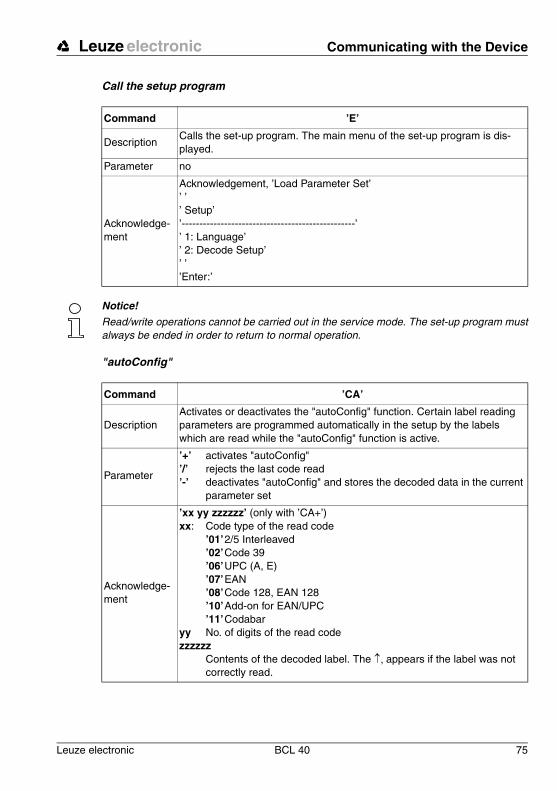
Leuze electronic Communicating with the Device
Leuze electronic BCL 40 75
TN
T 3
5/7-
24V
Call the setup program
Notice!
Read/write operations cannot be carried out in the service mode. The set-up program mustalways be ended in order to return to normal operation.
"autoConfig"
Command ’E’
DescriptionCalls the set-up program. The main menu of the set-up program is dis-played.
Parameter no
Acknowledge-ment
Acknowledgement, ’Load Parameter Set’’ ’’ Setup’’-------------------------------------------------’’ 1: Language’’ 2: Decode Setup’’ ’’Enter:’
Command ’CA’
DescriptionActivates or deactivates the "autoConfig" function. Certain label reading parameters are programmed automatically in the setup by the labels which are read while the "autoConfig" function is active.
Parameter
’+’ activates "autoConfig"’/’ rejects the last code read’-’ deactivates "autoConfig" and stores the decoded data in the current
parameter set
Acknowledge-ment
’xx yy zzzzzz’ (only with ’CA+’)xx: Code type of the read code
’01’2/5 Interleaved’02’Code 39’06’UPC (A, E)’07’EAN’08’Code 128, EAN 128’10’Add-on for EAN/UPC’11’Codabar
yy No. of digits of the read codezzzzzz
Contents of the decoded label. The �� appears if the label was not correctly read.

Communicating with the Device Leuze electronic
76 BCL 40 Leuze electronic
Manual definition of the reference code
Teach-In
Notice!
With this function, only code types are recognised that are identified using the "autoConfig"function or which were set in the set-up.
� After each reading via an ’RTx’ command, explicitly switch off the function again using the ’RT-’ command since failure to do so will interfere with other commands as well as prevent execution of a new ’RTx’ command.
Command ’RS’
Description
This command can be used to define a new reference code in the BCL 40 by means of direct entry via the serial interface. The data are saved in the parameter set according to their input under reference code 1 or 2 and stored in the working buffer for further processing.
Parameter
’RSyxxzzzzzzzz’y, x and z are place holders (variables) for the actual input. y: def. reference code No
’1’ (Code 1) ’2’ (Code 2) … xx def. code type (see command "’CA’" on page 75)
z def. code information (1 … 31 characters)
Acknowledge-ment
no
Example input = ’RS10678654331’ (Code 1 (1), UPC (06), 78654331)
Command ’RT’
DescriptionThis command enables a reference code to be defined quickly by reading an example label.
Parameter
’RTy’y: Function
’1’ defines reference code 1’2’ defines reference code 2 ’-’ exit the Teach-In process
Acknowledge-ment
zzzzzz Contents of the decoded label

Leuze electronic Communicating with the Device
Leuze electronic BCL 40 77
TN
T 3
5/7-
24V
Detect code
9.3.2 "Online" Commands for System Control
Activate sensor input 1
Deactivate sensor input 1
Command ’CC’
DescriptionReads the code type and contents of an unknown label without storing it in Setup.
Parameter no
Acknowledge-ment
xxyyzzzzzzThe acknowledgement is the same as that of the "autoConfig" function.
Command ’+’
DescriptionActivates decoding (sensor input 1). A signal can be simulated on sensor input 1 with this command.
Parameter no
Acknowledge-ment
no
Command ’-’
DescriptionDeactivates decoding (sensor input 1). A signal can be simulated on sen-sor input 1 with this command.
Parameter no
Acknowledge-ment
no

Communicating with the Device Leuze electronic
78 BCL 40 Leuze electronic
Activate sensor input 2
Deactivate sensor input 2
9.3.3 "Online" Commands for System Checking
Diagnosis laser
Command ’,’
DescriptionActivates the definition of reference code 1 (sensor input 2). A signal can be simulated on sensor input 2 with this command.
Parameter no
Acknowledge-ment
no
Command ’.’
DescriptionDeactivates the definition of reference code 1 (sensor input 2). A signal can be simulated on sensor input 2 with this command.
Parameter no
Acknowledge-ment
no
Command ’DL’
Description The command controls or tests the laser diode.
Parameter
’+’ switches on the laser diode’-’ switches off the laser diode’C’ outputs the laser current’T’ outputs the laser temperature.
Acknowledge-ment
no ’DS03’: invalid parameter for the command ’DL’’DS04’: invalid command length’DTxxx.x’ ’DCyyy’
xxx.x is the laser temperature in °Cyyy is the laser current in mA

Leuze electronic Communicating with the Device
Leuze electronic BCL 40 79
TN
T 3
5/7-
24V
Diagnosis motor
Supply voltage
Command ’DMS’
Description Returns the rotary frequency of the polygon mirror wheel drive motor.
Parameter no
Acknowledge-ment
’DMSxxxxx’
Descriptionxxxxx is the current rotary frequency of the motor in revolutions per minute.
Command ’DUV’
Description Returns the supply voltage of the BCL 40.
Parameter no
Acknowledge-ment
’DUVxx.x’
Description xx.x is the current supply voltage in V.

Communicating with the Device Leuze electronic
80 BCL 40 Leuze electronic
9.3.4 "Online" Commands for Querying Statistical Data
Query device statistics
Command ’SR’
DescriptionReturns the current contents of the given field of the statistical device data memory.
Parameter ’00’ to ’19’
Acknowledge-ment
’ST00XXXXX’ to ’ST19XXXXX’
Description
ST00XXXXX’: XXXXX is the length of time in seconds that the laser diode has been switched on since the last initialisation’ST01XXXXX’: XXXXX is the length of time in minutes that the polygon wheel motor has been switched on since the last initialisation’ST05XXXXX’: XXXXX the number of correctly received commands via the interface’ST06XXXXX’: XXXXX the number of incorrectly received commands via the interface’ST07XXXXX’: XXXXX the number of sent commands via the interface that have received positive acknowledgement’ST08XXXXX’: XXXXX the number of sent commands via the interface that have received negative acknowledgement’ST09XXXXX’: XXXXX the number of correctly received commands via the host’ST10XXXXX’: XXXXX the number of incorrectly received commands via the host’ST11XXXXX’: XXXXX the number of sent commands via the host that have received positive acknowledgement’ST12XXXXX’: XXXXX the number of sent commands via the host that have received negative acknowledgement’ST13XXXXX’: XXXXX is the number of scans since the last read enable’ST14XXXXX’: XXXXX is the number of read scans since the last reset’ST15XXXXX’: XXXXX is the number of read scans since the last read enable’ST16XXXXX’: XXXXX the number of read labels from the last scan’ST17XXXXX’: XXXXX is the number of read enables since the last reset’ST18XXXXX’: XXXXX the number of correctly decoded labels since the last reset’ST19XXXXX’: XXXXX the number of incorrectly decoded labels since the last reset

Leuze electronic Communicating with the Device
Leuze electronic BCL 40 81
TN
T 3
5/7-
24V
9.3.5 "Online" Commands for Parameter Set Operations
Test parameter set
Command ’PA’
Description Tests the given parameter set for validity using a checksum.
Parameter’0’ tests the current parameter set’1’ tests the customer-specific parameter set (MA 10 only)
Acknowledge-ment
’Psx’x: Status
'0' valid parameter set'1' invalid message'2' invalid message length'3' invalid block check type'4' invalid block check checksum'5' invalid data length'6' invalid message data '7' invalid start address'8' invalid parameter set'9' invalid parameter type

Communicating with the Device Leuze electronic
82 BCL 40 Leuze electronic
Copy parameter set
Notice!
A valid parameter set operation must be acknowledged with ’PS0’. Should an error occur,the command should be repeated. Repeated error acknowledgements indicate an error inthe parameter set. If in doubt, contact your Leuze sales or service office (see back page foraddresses).
Command ’PC’
Description Copies the given source parameter set into the given target parameter set
ParameterBCL 40 Stand alone:’0’ Current parameter set.’2’ parameter set with factory default settings.
Example ’PC20’: Reset to factory default settings
BCL 40 with MA 10:’0’ Current parameter set.’1’ customer-specific parameter set.’2’ parameter set with factory default settings.
Example
’PC20’: Reset to factory default settings’PC01’: The current parameter set is copied in the customer-specific
parameter set (backup)’PC10’: Reset to customer-specific settings
Acknowledge-ment
’PSx’x: Status
'0' valid parameter set'1' invalid message'2' invalid message length'3' invalid block check type'4' invalid block check checksum'5' invalid data length'6' invalid message data '7' invalid start address'8' invalid parameter set'9' invalid parameter type

Leuze electronic Maintenance
Leuze electronic BCL 40 83
TN
T 3
5/7-
24V
10 Maintenance
10.1 General Maintenance InformationUsually, the barcode reader BCL 40 does not require any maintenance by the operator.
CleaningShould it become soiled, clean the glass window of the BCL 40 with a soft cloth.
Notice!
Do not use aggressive cleaning agents such as thinner or acetone for cleaning the device.
10.2 Repairs, ServicingRepairs to the device must only be carried out by the manufacturer.
� Contact your Leuze distributor or service organisation should repairs be required.For addresses, please refer to the back page of this operating manual.

Appendix Leuze electronic
84 BCL 40 Leuze electronic
11 Appendix
11.1 ASCII Table
ASCII Dec. Hex. Oct. Symbol Meaning
NULL 0 00 0 NULL Null
SOH 1 01 1 START OF HEADING Start of heading
STX 2 02 2 START OF TEXT Start of text characters
ETX 3 03 3 END OF TEXT End of text characters
EOT 4 04 4 END OF TRANSMISS. End of transmission
ENQ 5 05 5 ENQUIRY Request for data trans.
ACK 6 06 6 ACKNOWLEDGE Positive acknowledgement
BEL 7 07 7 BELL Bell signal
BS 8 08 10 BACKSPACE Backwards step
HT 9 09 11 HORIZ. TABULATOR Horizontal tabulator
LF 10 0A 12 LINE FEED Line feed
VT 11 0B 13 VERT. TABULATOR Vertical tabulator
FF 12 0C 14 FORM FEED Form feed
CR 13 0D 15 CARRIAGE RETURN Carriage return
SO 14 0E 16 SHIFT OUT Shift out
SI 15 0F 17 SHIFT IN Shift in
DLE 16 10 20 DATA LINK ESCAPE Data link escape
DC1 17 11 21 DEVICE CONTROL 1 Device control character 1
DC2 18 12 22 DEVICE CONTROL 2 Device control character 2
DC3 19 13 23 DEVICE CONTROL 3 Device control character 3
DC4 20 14 24 DEVICE CONTROL 4 Device control character 4
NAK 21 15 25 NEG. ACKNOWLEDGE Negative acknowledgement
SYN 22 16 26 SYNCRONOUS IDLE Synchronisation
ETB 23 17 27 EOF TRANSM. BLOCK End of data trans. block
CAN 24 18 30 CANCEL Invalid
EM 25 19 31 END OF MEDIUM End of message
SUB 26 1A 32 SUBSTITUTE Substitution
ESC 27 1B 33 ESCAPE Escape
FS 28 1C 34 FILE SEPARATOR File separator
GS 29 1D 35 GROUP SEPARATOR Group separator
RS 30 1E 36 RECORD SEPARATOR Record separator

Leuze electronic Appendix
Leuze electronic BCL 40 85
TN
T 3
5/7-
24V
US 31 1F 37 UNIT SEPARATOR Unit separator
SP 32 20 40 SPACE Space
! 33 21 41 EXCLAMATION POINT Explanation point
" 34 22 42 QUOTATION MARK Quotation mark
# 35 23 43 NUMBER SIGN Number sign
$ 36 24 44 DOLLAR SIGN Dollar sign
% 37 25 45 PERCENT SIGN Percent sign
& 38 26 46 AMPERSAND Ampersand
’ 39 27 47 APOSTROPHE Apostrophe
( 40 28 50 OPEN. PARENTHESIS Open parenthesis
) 41 29 51 CLOS. PARENTHESIS Closed parenthesis
* 42 2A 52 ASTERISK Asterisk
+ 43 2B 53 PLUS Plus sign
, 44 2C 54 COMMA Comma
- 45 2D 55 HYPHEN (MINUS) Hyphen
. 46 2E 56 PERIOD (DECIMAL) Period
/ 47 2F 57 SLANT Slant
0 48 30 60 0 Number
1 49 31 61 1 Number
2 50 32 62 2 Number
3 51 33 63 3 Number
4 52 34 64 4 Number
5 53 35 65 5 Number
6 54 36 66 6 Number
7 55 37 67 7 Number
8 56 38 70 8 Number
9 57 39 71 9 Number
: 58 3A 72 COLON Colon
; 59 3B 73 SEMI-COLON Semicolon
< 60 3C 74 LESS THEN Less than
= 61 3D 75 EQUALS Equal sign
> 62 3E 76 GREATER THEN Greater than
? 63 3F 77 QUESTION MARK Question mark
@ 64 40 100 COMMERCIAL AT Commercial at character
A 65 41 101 A Capital letter
ASCII Dec. Hex. Oct. Symbol Meaning

Appendix Leuze electronic
86 BCL 40 Leuze electronic
B 66 42 102 B Capital letter
C 67 43 103 C Capital letter
D 68 44 104 D Capital letter
E 69 45 105 E Capital letter
F 70 46 106 F Capital letter
G 71 47 107 G Capital letter
H 72 48 110 H Capital letter
I 73 49 111 I Capital letter
J 74 4A 112 J Capital letter
K 75 4B 113 K Capital letter
L 76 4C 114 L Capital letter
M 77 4D 115 M Capital letter
N 78 4E 116 N Capital letter
O 79 4F 117 O Capital letter
P 80 50 120 P Capital letter
Q 81 51 121 Q Capital letter
R 82 52 122 R Capital letter
S 83 53 123 S Capital letter
T 84 54 124 T Capital letter
U 85 55 125 U Capital letter
V 86 56 126 V Capital letter
W 87 57 127 W Capital letter
X 88 58 130 X Capital letter
Y 89 59 131 Y Capital letter
Z 90 5A 132 Z Capital letter
[ 91 5B 133 OPENING BRACKET Opening bracket
\ 92 5C 134 REVERSE SLANT Reverse slant
] 93 5D 135 CLOSING BRACKET Closing bracket
^ 94 5E 136 CIRCUMFLEX Circumflex
_ 95 5F 137 UNDERSCORE Underscore
‘ 96 60 140 GRAVE ACCENT Grave accent
a 97 61 141 a Lower case letter
b 98 62 142 b Lower case letter
c 99 63 143 c Lower case letter
d 100 64 144 d Lower case letter
ASCII Dec. Hex. Oct. Symbol Meaning

Leuze electronic Appendix
Leuze electronic BCL 40 87
TN
T 3
5/7-
24V
Table 11.1: ASCII Table
e 101 65 145 e Lower case letter
f 102 66 146 f Lower case letter
g 103 67 147 g Lower case letter
h 104 68 150 h Lower case letter
i 105 69 151 i Lower case letter
j 106 6A 152 j Lower case letter
k 107 6B 153 k Lower case letter
l 108 6C 154 l Lower case letter
m 109 6D 155 m Lower case letter
n 110 6E 156 n Lower case letter
o 111 6F 157 o Lower case letter
p 112 70 160 p Lower case letter
q 113 71 161 q Lower case letter
r 114 72 162 r Lower case letter
s 115 73 163 s Lower case letter
t 116 74 164 t Lower case letter
u 117 75 165 u Lower case letter
v 118 76 166 v Lower case letter
w 119 77 167 w Lower case letter
x 120 78 170 x Lower case letter
y 121 79 171 y Lower case letter
z 122 7A 172 z Lower case letter
{ 123 7B 173 OPENING BRACE Opening brace
| 124 7C 174 VERTICAL LINE Vertical line
} 125 7D 175 CLOSING BRACE Closing brace
~ 126 7E 176 TILDE Tilde
DEL 127 7F 177 DELETE (RUBOUT) Delete
ASCII Dec. Hex. Oct. Symbol Meaning

Appendix Leuze electronic
88 BCL 40 Leuze electronic
11.2 Example Bar Code Label Types
11.2.1 Module 0.3
Figure 11.1: Bar code sample labels (module width 0.3)
SC 2
SC 3
SC 0 S
Modul 0,3
Modul 0,3
Modul 0,3
Modul 0,3
Modul 0,3
1122334455
135AC
A121314A
abcde
leuze
23456 2789011
3456 7890
1 122334 455666
77889
Code type 01: Interleaved 2 of 5
Code type 02: Code 39
Code type 11: Codabar
Code 128
Code type 08: EAN 128
Code type 06: UPC-A
Code type 07: EAN 8
Code type 10: EAN 13 Add-on

Leuze electronic Appendix
Leuze electronic BCL 40 89
TN
T 3
5/7-
24V
11.2.2 Module 0.5
Figure 11.2: Bar code sample labels (module 0.5)
Modul 0,5
6677889900
Modul 0,5
246BD
Modul 0,5
A151617A
Modul 0,5
fghij
Modul 0,5
LEUZE
SC 4
98765 432190 8
SC 6
9876 5430
SC 2
0 099887 766550
44332
Code type 01: Interleaved 2 of 5
Code type 02: Code 39
Code type 11: Codabar
Code 128
Code type 08: EAN 128
Code type 06: UPC-A
Code type 07: EAN 8
Code type 10: EAN 13 Add-on


Ing. Franz Schmachtl KGTel. Int. + 43 (0) 732/7646-0Fax Int. + 43 (0) 732/785036E-mail: [email protected]
Nortécnica S. R. L.Tel. Int. + 54 (0) 11/4757-3129Fax Int. + 54 (0) 11/4757-1088E-mail: [email protected]
+
Balluff-Leuze Pty. Ltd.Tel. Int. + 61 (0) 3/97642366Fax Int. + 61 (0) 3/97533262E-mail: [email protected]
Leuze electronic nv/saTel. Int. + 32 (0) 2/2531600Fax Int. + 32 (0) 2/2531536E-mail: [email protected]
Leuze electronic Ltda.Tel. Int. + 55 (0) 11/ 4195-6134Fax Int. + 55 (0) 11/ 4195-6177E-mail: [email protected]
Leuze electronic AGTel. Int. + 41 (0) 1/8340204Fax Int. + 41 (0) 1/8332626E-mail: [email protected]
TR Electronic GmbHShanghai Rep. OfficeTel. Int. + 8621/58314825Fax Int. + 8621/58314829E-mail: [email protected]
Schmachtl CZ Spol. SR. O.Tel. Int. + 420 (0) 2/44001500Fax Int. + 420 (0) 44910700E-mail: [email protected]://www.schmachtl.cz
Componentes Electronicas Ltda.Tel. Int. + 57 (0) 4/3511049Fax Int. + 57 (0) 4/3511019E-mail: [email protected]
Desim Elektronik APSTel. Int. + 45/70220066Fax Int. + 45/70222220E-mail: [email protected]
Leuze electronic GmbH + Co.Geschäftsstelle DresdenTelefon (0351) 2841105Telefax (0351) 2841103E-mail: [email protected]
Lindner electronic GmbHVertrieb Nord, HannoverTelefon (0511) 966057-0Telefax (0511) 966057-57E-mail: [email protected]
W+M plantechnikDipl.-Ing. Wörtler GmbH + Co.Vertrieb West, WuppertalTelefon (0202) 37112-0Telefax (0202) 318495E-mail: [email protected]
Leuze electronic GmbH + Co.Geschäftsstelle FrankfurtTelefon (06181) 9177-0Telefax (06181) 917715E-mail: [email protected]
Leuze electronic GmbH + Co.Geschäftsstelle Owen/Bad.-Württ.Telefon (07021) 9850-910Telefax (07021) 9850-911E-mail: [email protected]
Leuze electronic GmbH + Co.Geschäftsstelle MünchenTelefon (08141) 5350200Telefax (08141) 5350220E-mail: [email protected]
Leuze electronic S.A.Tel. Int. + 34 93/4097900Fax Int. + 34 93/4903515E-mail: [email protected]
Leuze electronic sarl.Tel. Int. + 33 (0) 1/60051220Fax Int. + 33 (0) 1/60050365E-mail: [email protected]://www.leuze-electronic.fr
SKS-automaatio OyTel. Int. + 358 (0) 9/852661Fax Int. + 358 (0) 9/8526820E-mail: [email protected]://www.sks.fi
Leuze Mayser electronic Ltd.Tel. Int. + 44 (0) 1480/408500Fax Int. + 44 (0) 1480/403808E-mail: [email protected]://www.leuzemayser.co.uk
UTECO A.B.E.E.Tel. Int. + 30 (0) 1/4 210050Fax Int. + 30 (0) 1/4 212033E-mail: [email protected]
+ + +
All ImpexTel. + Fax + 7 095/9332097
Kvalix Automatika Kft.Tel. Int. + 36 (0) 1/3990615Fax Int. + 36 (0) 1/3698488E-mail: [email protected]://www.kvalix.hu
Sensortech CompanyTel. Int. + 852/26510188Fax Int. + 852/26510388E-mail: [email protected]
IVO Leuze Vogtle Malanca s.r.l.Tel. Int. + 39 02/26110643Fax Int. + 39 02/26110640E-mail: [email protected]://www.ivoleuze.com
Galoz electronics Ltd.Tel. Int. + 972 (0) 3/9023456Fax Int. + 972 (0) 3/9021990
Global Tech Corp.Tel. Int. + 91 (0) 20/4470085Fax Int. + 91 (0) 20/4 470086E-mail: [email protected]
SSR Engineering Co., Ltd.Tel. Int. + 81 (0) 45/ 730-5580Fax Int. + 81 (0) 45/ 730-5587E-mail: [email protected]
Leuze electronic Co., Ltd.Tel. Int. + 82 (0) 31/3828228Fax Int. + 82 (0) 31/3828522E-mail: [email protected]://www.leuze.co.kr
Ingermark (M) SDN.BHDTel. Int. + 60 (0) 3/60342788Fax Int. + 60 (0) 3/60342188E-mail: [email protected]
Leuze Lumiflex México, S.A. de C.V.Tel. Int. + 52 (0) 8/3524060Fax Int. + 52 (0) 8/3524034E-mail: [email protected]://www.leuze.de
Elteco A/STel. Int. + 47 (0) 35/573800Fax Int. + 47 (0) 35/573849E-mail: [email protected]://www.elteco.no
Leuze electronic B.V.Tel. Int. + 31 (0) 418/653544Fax Int. + 31 (0) 418/653808E-mail: [email protected]://www.leuze.nl
LA2P, Lda.Tel. Int. + 351 (0) 21/4447070Fax Int. + 351 (0) 21/4447075E-mail: [email protected]://www.la2p.pt
Balluff Sp. z. o. o.Tel. Int. + 48 (0) 22/6519679Fax Int. + 48 (0) 22/8429728E-mail: [email protected]
Imp. Tec. Vignola S.A.I.C.Tel. Int. + 56 (0) 32/256521 Fax Int. + 56 (0) 32/258571E-mail: [email protected]
Great Cofue Technology Co., Ltd.Tel. Int. + 886 (0) 2/29838077Fax Int. + 886 (0) 2/29853373E-mail: [email protected]
Countapulse Controls (PTY.) Ltd.Tel. Int. + 27 (0) 11/6157556-8Fax Int. + 27 (0) 11/6157513
Leuze electronic ABTel. + 46 (0) 8/7315190Fax + 46 (0) 8/7315105E-mail: [email protected]
+ +
Balluff Asia Pte LtdTel. Int. + 65/2524384Fax Int. + 65/2529060E-mail: [email protected]
Schmachtl SK s.r.o.Tel. Int. + 421 (0) 7/54777484Fax Int. + 421 (0) 7/54777491E-mail: [email protected]
Tipteh d.o.o.Tel. Int. + 386 (0) 1/ 2005150Fax Int. + 386 (0) 1/ 2005151E-mail: [email protected]://www.tipteh.si
Industrial Electrical Co. Ltd.Tel. Int. + 66 (0) 2/6 42-6700Fax Int. + 66 (0) 2/6 42-4249
MEGA Teknik elek. San. ve Tic. Ltd.Tel. Int. + 90 (0) 212/3200411Fax Int. + 90 (0) 212/3200416E-mail: [email protected]
+
Leuze Lumiflex Inc.Tel. Int. + 1 (0) 973/5860100Fax Int. + 1 (0) 973/586 1590E-mail: [email protected]://www.leuze-lumiflex.com
CDNUSA
TR
TH
SLO
SK
RPRISGP
S
RSA
ROC
RCH
PL
P
NL
N
MEX
MAL
KOR
J
IND
IL
I
HK
H
LTLVESTRUS
GR
GB
FIN
F
E
D
DK
CO
CZ
CHN
CH
BR
B
NZAUS
ARG
A
Leuze electronicLeuze electronic GmbH + Co.Postfach 11 11, D-73277 Owen/TeckTel. (07021) 5730, Fax (07021) 573199E-mail: [email protected]://www.leuze.de
Sales and Service
GB
079
/03
– 04
/02
P
art.
No.
500
27
316