worth data wdp keyboard wedge reader users manual · pdf fileworth data wdp keyboard wedge...
TRANSCRIPT

Worth DataWDP KeyboardWedge ReaderUsers Manual
For Model P11/12
i
Introduction Worth Data' WDP Readers are versatile bar code readers that attach to the IBMPC, XT and AT; all IBM PS/2 Models; any PC keyboard-compatible or bus-compatible unit; and all Macintosh ADB models. The WDP provides bar codeinput data to any host computer program exactly as if the data had been typed atthe keyboard, including function and control key support. WDP Reader featuresinclude:
The WDP Reader automatically reads and discriminates between Code 39,Full ASCII Code 39, Interleaved 2 of 5, Codabar, Code 128, EAN-13, EAN-8, UPC-E, UPC-A (with or without supplements), MSI, LabelCode4,LabelCode5, Code 93, and Plessey.
• Bar codes
• PC or Macintosh InterfaceThe WDP Reader is presently the only reader capable of internal or externalinstallation on PCs (External-only on Microchannel PS/2's and theMacintosh.) For external mounting, its lightweight, unobtrusive case can beattached to the side of the computer, monitor or desk with Velcro. For internalmounting, the board is easily removed from the case and inserted into a PC'sISA slot. If your MAC or PC has only a USB port for keyboard attachment,the USB Wedge Saver bridges the WDP to a USB port.
• Scanner optionsThe WDP Reader comes with a high quality USA-made stainless steel wandscanner. Additional scanner options include moving-beam laser scanners,CCD scanners, MagStripe scanners for reading credit card magnetic strips,and bar code slot scanners for badges and other thin, flat surfaces.
• Integrated Laser & Integrated CCD Wedge ReaderThe Integrated Laser Readers and the Integrated CCD Readers are completeWDP Readers with the decoder built into the scanner handle. Just plug theunit in between your computer and keyboard and you're ready to go. Theywork with any PC keyboard-compatible computer, all Macintosh ADBmodels and USB computers (using the Wedge Saver).
• Configuration is easyThe WDP Reader is easily configured for your system by scanning a bar codedSetup Menu. There are no dip switches to set. On the separate decodermodels, opening of the reader's case is required only for internal businstallation, Track 1&2 Magstripe, and for setting the decode light on a laseror CCD Scanner. The PC/PS2 Y cable can be switched from 5 pin to 6 pinand vice versa.

1-1
Chapter 1
Installation
Components of WDP ReaderIn the event the shipping box shows damage on arrival, please note the damage onthe carrier's receipt log. Open the box and inspect the contents for damage. Ifthere is visible damage, or if the unit fails to work, contact us with the details of thetrouble; we will be happy to send you a replacement.
The contents of your WDP Reader shipment should include the following:
1. A WDP Reader in a lightweight box, or an Integrated Laser Reader or anIntegrated CCD Wedge Reader.
2. Velcro strips which can be used to conveniently attach the reader to the side of your computer, monitor or desk.
3. A "Y" cable for attaching the WDP Reader between your computer and keyboard to a 5 pin din or 6 pin minidin keyboard connector; or if you have a USB only computer, a straight cable with the USB Wedge Saver for attachment to the USB port of your computer.
4. A rugged stainless-steel bar code wand (unless you have an Integrated Laser or Integrated CCD Wedge Reader, or ordered a different input device such as a laser scanner or slot scanner).
5. A plastic wand or laser-scanner holder.
6. A laminated Reader Setup Menu sheet (or slot-scanner card deck).
You probably didn't receive a power supply with your WDP - even thoughyour external WDP decoder box has a Power jack. Power supplies are rarelyneeded. Using a power suppply other than a Worthington Data Power Supply,(i.e. our part number F10 for 110v), will probably burn out the WDP circuitboard. Damage caused by non-Worthington power supply which is notcovered by warranty. DON'T PLUG OTHER POWER SUPPLIES INTOTHE WDP -- even if the connector does fit, you will fry the WDP board.
1-2
InstallationThe several methods of WDP attachment are:
• External Wedge
The Reader is placed near the computer, and is connected between thecomputer and keyboard. Velcro is included for convenient attachment toyour computer, monitor, desk, etc. Bar code data is received via thecomputer's keyboard port.
• Internal Installation on PC (P11/12)
The WDP Reader Models P11/12/P01 have a printed circuit boardwhich can be removed from the case and mounted in any unused PC'sISA slot.
Internal Wedge mounting uses the slot for physical mounting only -- itdoesn't communicate with the bus. Cables connect the board level readerbetween the computer and keyboard; bar code data is received by thekeyboard port. DOS users can also install the WDP P11/12 so that itcommunicates with the bus instead of the keyboard interface. If youprefer Internal Installation, see Appendix B for details.
The Lasers and CCD are available in the decoder built into the scannerhousing, thereby eliminating the separate decoder. These models of theWDP are:
• Integrated Laser WDP Readers
These readers have to be attached externally. The LZ100-WDP andLZ200-WDP Readers are laser scanners with the decoder built into thescanner housing. They are connected between the computer andkeyboard using a Y cable or the USB Wedge Saver. Decoded bar code datais transmitted as though it has been keyed. These readers do not requirea separate decoder box; however there is no power supply option for lowpowered PCs, and there is no second scanner attachment possible.99.99% of PCs have sufficient power.
• Integrated CCD Wedge Reader
This reader has to be attached externally. The Integrated CCD Reader hasthe decoder built into the scanner case. Connected between yourcomputer and keyboard, or to the USB Wedge Saver, it transmits decodedbar code data to the computer's keyboard port. These readers do notrequire a separate decoder box; however there is no power supply optionfor low powered PCs, and there is no second scanner attachment possible.99.99% of PCs have sufficient power.
1-3
External Wedge Installation on PC or Mac
1. Unplug the keyboard cable from where it plugs into the back of thecomputer, and note its location. (Note: the PC's F30/1 Y cable is convertible from a 5 pin cable to a 6 pin minidin by simply switchingthe adapter from one side of the Y cable to another, so match your keyboard requirement. Be sure not to plug into the mouse port by mistake.
2. Plug the keyboard cable into the "Y" cable's round female DIN connector.
3. With the power OFF on the computer, Plug the "Y" cable's male DIN connector into the back of the PC where the keyboard previously plugged into. For the Mac, plug into any ADB port; but,preferably on the host.
4. Plug the modular telephone style jack at the Y end of the "Y" cable into the WDP Reader's "Y" cable port. If you have an Integrated Laser or Integrated CCD, the RJ45 telephone connector end of the"Y" cable will plug into the Integrated Laser or Integrated CCD's small black "coupling connector" instead.
5. If you have a decoder box, plug the wand, laser scanner, CCD touchscanner or bar code slot scanner into the WDP Reader's Wand port.(If you have a MagStripe slot scanner, see page 21 for its installationinstructions.)
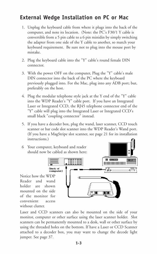
6 Your computer, keyboard and reader should now be cabled as shown here:
Notice how the WDPReader and wandholder are shownmounted on the sideof the monitor forconvenient accesswithout clutter.
Laser and CCD scanners can also be mounted on the side of yourmonitor, computer or other surface using the laser scanner holder. Slotscanners can be permanently mounted to a desk, wall or other surface byusing the threaded holes on the bottom. If have a Laser or CCD Scannerattached to a decoder box, you may want to change the decode lightjumper. See page 37.
1-4
USB Installation on a PC or Mac
If you are attaching a WDP to a computer which doesn't have a traditionalkeyboard port, (5 or 6 pin din on PC or ADB on Mac), and only has a USB portfor attaching a keyboard, you must use the Wedge Saver to bridge the WDP to theUSB port.
When you plug the Wedge Saver into the USB port, Windows-98 or the Mac willsense the new device and proceed to install the necessary software. You don't needany additional drivers other than what is already on Windows or Mac OS. After thesoftware installation completes, follow these instructions:
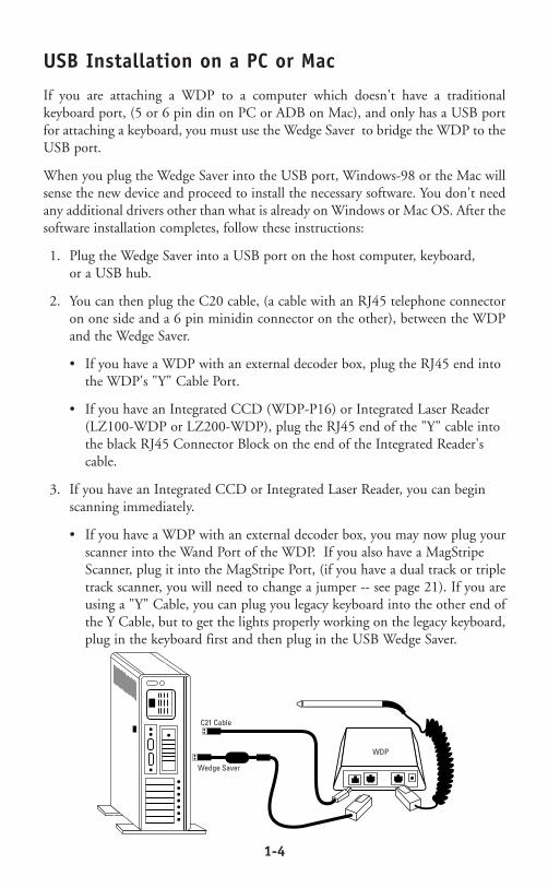
1. Plug the Wedge Saver into a USB port on the host computer, keyboard, or a USB hub.
2. You can then plug the C20 cable, (a cable with an RJ45 telephone connectoron one side and a 6 pin minidin connector on the other), between the WDPand the Wedge Saver.
• If you have a WDP with an external decoder box, plug the RJ45 end into the WDP's "Y" Cable Port.
• If you have an Integrated CCD (WDP-P16) or Integrated Laser Reader (LZ100-WDP or LZ200-WDP), plug the RJ45 end of the "Y" cable into the black RJ45 Connector Block on the end of the Integrated Reader's cable.
3. If you have an Integrated CCD or Integrated Laser Reader, you can begin scanning immediately.
• If you have a WDP with an external decoder box, you may now plug yourscanner into the Wand Port of the WDP. If you also have a MagStripe Scanner, plug it into the MagStripe Port, (if you have a dual track or tripletrack scanner, you will need to change a jumper -- see page 21). If you areusing a "Y" Cable, you can plug you legacy keyboard into the other end ofthe Y Cable, but to get the lights properly working on the legacy keyboard,plug in the keyboard first and then plug in the USB Wedge Saver.
Wedge Saver
WDP
C21 Cable

2-1
Chapter 2
WDP Reader SetupConfiguring the WDP Reader for your computerand application...
Turn on your computer: You should hear three beeps -- anindication the WDP Reader is functioning correctly.
Find the laminated Reader Setup Menu sheet and look itover. (For bar code slot scanners, the Reader Setup Menuis a deck of bar coded cards.) This simple menu lets youeasily configure the WDP Reader to work with almost anycomputer system, and tailor its bar code reading and dataformat characteristics precisely to your needs. To scanReader Setup Menu bar codes and configure your reader,
you must know the right way to scan bar codes. If you are new to scanning, be sureto read Appendix K - Scanning Instruction.
These are the WDP Reader's default settings. The WDP Reader is shippedconfigured to these settings, and can be reset to them at any time by reading theStart Setup and Reset bar codes on the Reader Setup Menu. If you need to changeany settings, or want to learn more about the WDP Reader options, the next pagesexplain, step by step, how to set them and what they do.
WDP Reader Setup Menu
Code 39 Code 39 enabled MSI/Plessey MSI/Plessey disabledCheck Digit disabled Check Digits not transmittedStart/Stop characters not transmitted Label Code 4/5 disabledAccumulate Mode enabledCaps Lock OFF
2 of 5 I 2of 5 disabled Code 128 Code 128 disabled6 digit code length UCC-128/EAN disabledCheck digit disabled
UPC/EAN UPC/EAN enabled Code 93 Code 93 disabledUPC Supplements disabled Full ASCII estension disabledUPC-E compressed, NSC of 0Transmit UPC-A in UPC-A formatISBN conversion disabledUPC-A NSC and EAN-13 first two characters and check digits transmittedUPC-E NSC and EAN-8 first two characters and check digits not transmitted
General Configuration AT with USA keyboardSettings Data Transmission timing NONE
NO preamble or postamble setCR as Terminator CharacterMedium pitch beep toneNo MagStripe slot scanner attached
Parameter Default Setting Parameter Default Setting
2-2
Using the WDP Reader Setup Menu
1If you have never scanned before, refer to Appendix K for ScanningInstructions. To configure your reader using the Reader Setup Menu, youmust first scan the Start Setup code at the top left corner. Do this now.
You'll hear two beeps. During Setup, nothing will be transmitted to youromputer; the Reader Setup Menu codes are strictly for configuring the reader.If you did not hear two beeps, try scanning the code again, until you hear thetwo beeps.
2Next, choose the topic you want to change an option for, and scan itscode. Let's use Beep Tone, at the lower left corner of the menu, as anexample. Scan the Beep Tone code now. You'll hear two beeps.
3Then, choose the option you want to change, from the list next to thetopic bar code you just scanned. For Beep Tone, the options range from0 for the lowest pitch to 4 for the highest pitch. Using the "Barpad
Table" on the right side of the Reader Setup Menu, scan the number or letterassociated with the option you have selected. Let's change the beep pitch toHighest. Now scan the 4 on the "Barpad Table". You will again hear twobeeps.
4Now scan End Setup (at the top-right corner of the Reader Setup Menuto complete the setup exercise. You'll hear three beeps. If you followedthe instructions correctly and successfully changed beep tone to
"highest", the three beeps will be higher in pitch than the other beeps hadbeen. If they aren't higher in pitch, repeat the steps on this page until you aresuccessful at changing the beep tone.
Now that your beep tone is at the "highest" pitch, you may want to change itback to "medium" or a different setting. Repeat the steps above, selecting theoption you prefer to "highest" in step 3.
When you've successfully changed the beep pitch, and are ready to configurethe reader for your specific application, scan Start Setup again. Continuescanning topics and options until you've made all the changes you desire, andthen scan End Setup to complete setup.
The next chapter will take you step by step through configuring each WDPReader option. Default settings are shown in bold in this manual and markedwith an * on the Reader Setup Menu.

2-3
WDP Setup ParametersBeep Tone
Lowest 0Low 1Medium 2High 3Highest 4Turn Beeper OFF 5
The WDP Reader gives you a choice of five different beep pitches. (Beep volumeis also adjustable -- see page 32 for the details.)
Code 39
Enable Code 39 0Disable Code 39 1Enable Full ASCII Code 39 2Disable Full ASCII Code 39 3Enable Code 39 Accumulate Mode 4Disable Code 39 Accumulate Mode 5Enable Start/stop character transmission 6Disable Start/Stop character transmission 7Enable Mod 43 Check Digit 8Disable Mod 43 Check Digit 9Enable Check Digit Transmission ADisable Check Digit Transmission BCaps Lock ON CCaps Lock OFF D
For information about Code 39, Full ASCII Code 39 and Accumulate Mode, seeAppendix D.
Enabling Start/Stop character transmission means that the WDP Reader willtransmit the * Start/Stop characters to your computer along with the data. Forexample, data of 1234 would be transmitted as *1234*. Most people don't needthis option, but it is useful if you want your software to be able to differentiatebetween keyboard and bar code data.
Enabling the Mod 43 Check Digit requires the units position of your data tomatch the calculation for the check digit explained in Appendix D. If you'veenabled the check digit, enabling Check Digit transmission causes the reader totransmit the check digit to your computer along with the bar code data.
"Caps Lock ON" means that lower case letters read as data will be transmitted asupper case, and upper case as lower. Numbers, punctuation and control charactersare not affected. "Caps Lock OFF" means that letters will be transmitted exactly asread.

2-4
UPC/EAN
Enable UPC/EAN 0 Disable UPC/EAN 1Enable UPC/EAN Supplements 2Disable UPC/EAN Supplements 3 Enable transmission of UPC-A NSC and EAN-13 first two digits 4Disable transmission of UPC-A NSC and EAN-13 first two digits 5 Enable transmission of UPC-A/EAN-13 Check Digit 6Disable transmission of UPC-A/EAN-13 Check Digit 7Enable transmission of UPC-E NSC and EAN-8 first digit 8Disable transmission of UPC-E NSC and EAN-8 first digit 9Enable transmission of UPC-E/EAN-8 Check Digit ADisable transmission of UPC-E/EAN-8 Check Digit BUPC-E Compressed CUPC-E Expanded DEAN-8 observes 9 and A above EEAN-8 if forced to transmit 8 digits FUPC-A transmitted in UPC-A format (see below)UPC-A transmitted in EAN-13 format (see below)ISBN conversion disabled (see below)ISBN conversion enabled (see below)
For general information about UPC and EAN, see Appendix G.
Enabling supplements allows you to read 2 and 5-digit supplemental codes usedwith magazines and books. This disallows right-to-left reading of UPC/EANcodes, to assure that the supplement doesn't get skipped.
Enabling transmission of UPC or EAN NSC's (leading digits, 1 for UPC;2 forEAN-13) or Check Digits means that these digits will be transmitted to yourcomputer along with the rest of the UPC or EAN data.
UPC-E Compressed Format transmits UPC-E codes as is; Expanded Format addszeros to make them the same length as UPC-A.
UPC-E can be used in either normal UPC-E format (implicit NSC of 0) or UPC-E1 format (NSC of 1). UPC-E1 is enabled by wanding 2 of 5 Code and 8 (9disables UPC-E1). It is very easy to read an EAN-13 bar code partially as UPC-E1,so don't enable UPC-E1 when reading EAN-13.
If you wish the UPC-A data to be transmitted in EAN-13 format, (with anadditional leading 0 for the USA's country code), you should scan TerminatorCharacter and F. Scanning E, the default, sets UPC back to no country codetransmitted.
ISBN bar codes are EAN-13 bar codes where the first three digits are the"Bookland" country code of 978 for books and 977 for periodicals, and thefollowing nine are the first nine digits of the ISBN. To enable transmission of ISBN

2-5
Code 93
Enable 0Disable 1Enable Full ASCII 2Disable Full ASCII 3
For more information about Code 93, See Appendix J
2 of 5 Code
Enable Interleaved 2 of 5 0Disable Interleaved 2 of 5 1Enable Interleaved 2 of 5 check digit 2Disable Interleaved 2 of 5 check digit 3Enable check digit transmission 4Disable check digit transmission 5Enable Standard 2 of 5 6Disable Standard 2 of 5 7
For information about Interleaved 2 of 5, see Appendix F.
Enabling the check digit requires that the data’s units position (last character) match thecalculation for the check digit explained in Appendix F. If you have enabled the check digitand want to transmit the check digit to the computer along with the rest of the bar codedata, choose “Enable check digit transmission”.
2 of 5 Data Length
Default Length 06
2 of 5 Code is so susceptible to interpreting partial scans as valid reads that theWDP Reader uses fixed-length data as a safeguard. To choose a data length, scanit as a two-digit number using the Barpad Table. For example, to select 8-digit datalength, you would scan a 0 and then a 8. Because Interleaved 2 of 5 is required tobe an even number of digits in length, you must use an even number. If you'reunsure of your bar code length, temporarily set length to 00, read a bar code, andcount its digits. Variable-length 2 of 5 codes are not recommended.
bar codes in ISBN format (the nine ISBN digits plus a new calculated mod-11check digit), scan Terminator Character and 11D. Scanning C, the default,disables conversion to ISBN format.

2-6
Code 128
Disable Code 128 0Enable Code 128 1Disable UCC-128/EAN-128 2 Enable UCC-128/EAN-128 3Enable Storage Tek Tape Label Code CDisable Storage Tek Tape Label Code DBar Code ID’s transmitted EBar Code ID’s not transmitted F
Bar Code ID’s are characters assigned to each bar code type to identify thatparticular type of code. These Bar Code ID’s can be used to identify what type ofbar code you are using when you are not sure or you want your application todifferentiate between the different types. The Bar Code ID’s are assigned as follows:
Codabar a Code 39 bUPC-A c EAN-13 dI 2 of 5 e 2 of 5 (standard) fCode 128 g Code 93 iMSI j magstripe data mUPC-E(0) n UPC-E1 (1) oEAN-8 p Storage Tek sPlessey x LabelCode 4 yLabelCode 5 z
Bar Code ID Bar Code ID
Codabar
Enable Codabar 0Disable Codabar 1Enable CLSI Codabar 2Disable CLSI Codabar 3Disable Start/Stop character transmission 4Enable Start/Stop character transmission 5
For information about Codabar, see Appendix E.
CLSI format is a form of Codabar often used by libraries
Enabling Start/Stop character transmission means that the WDP will transmit the Startand Stop characters to your computer along with the bar code data. Enable transmission ifyou are varying the Start and Stop characters according to label type in order to differentiatebetween bar code data and data from the keyboard. Most people do not need to transmitthe Start/Stop characters.
2-7
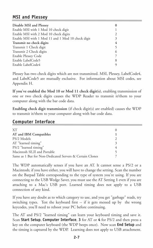
MSI and Plessey
Disable MSI and Plessey 0Enable MSI with 1 Mod 10 check digit 1Enable MSI with 2 Mod 10 check digits 2Enable MSI with 1 Mod 11 and 1 Mod 10 check digit 3Transmit no check digits 4Transmit 1 Check digit 5Transmit 2 Check digits 6Enable Plessey Code 7Enable LabelCode5 8Enable LabelCode4 9
Plessey has two check digits which are not transmitted. MSI, Plessey, LabelCode4,and LabelCode5 are mutually exclusive. For information about MSI codes, seeAppendix H.
If you've enabled the Mod 10 or Mod 11 check digit(s), enabling transmission ofone or two check digits causes the WDP Reader to transmit it/them to yourcomputer along with the bar code data.
Enabling check digit transmission (if check digit(s) are enabled) causes the WDPto transmit it/them to your computer along with bar code data.
Computer Interface
XT 0AT and IBM Compatibles 1PS/2 Models 2AT "learned timing" 3PS/2 "learned timing" 4Macintosh SE,II and Portable 5Same as 1 But for Non-Dedicated Servers & Certain Clones 7
The WDP automatically senses if you have an AT. It cannot sense a PS/2 or aMacintosh; if you have either, you will have to change the setting. Scan the numberon the Barpad Table corresponding to the type of system you're using. If you areconnecting to the USB Wedge Saver, you must use the AT Setting 1 even if you areattaching to a Mac's USB port. Learned timing does not apply to a USBconnection of any kind.
If you have any doubt as to which category to use, and you get "garbage" reads, tryswitching types. Test the keyboard first -- if it gets messed up by the wrongkeycodes, you'll need to reboot your PC before continuing.
The AT and PS/2 "learned timing" can learn your keyboard timing and save it.Scan Start Setup, Computer Interface, 3 for AT or 4 for PS/2 and then press akey on the computer keyboard (the WDP beeps once). Now scan End Setup andthe timing is captured by the WDP. Learning does not apply to USB attachment.
2-8
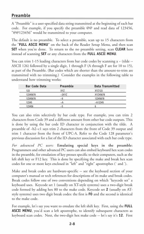
Preamble
A "Preamble" is a user-specified data string transmitted at the beginning of each barcode. For example, if you specify the preamble @@ and read data of 123456,"@@123456" would be transmitted to your computer.
The default is no preamble. To select a preamble, scan up to 15 characters fromthe "FULL ASCII MENU" on the back of the Reader Setup Menu, and then scanSET when you're done. To return to the no preamble setting, scan CLEAR hereinstead of scanning SET or any characters from the FULL ASCII MENU.
You can trim 1-15 leading characters from bar code codes by scanning a ~ (tilde --ASCII 126) followed by a single digit, 1 through F (A through F are for 10 to 15),as part of the Preamble. (Bar codes which are shorter than the amount-to-trim aretransmitted with no trimming.) Consider the examples in the following table tounderstand how trimming works:
Bar Code Data Preamble Data Transmitted123 XYZ XYZ12312345678 ~3XYZ XYZ4567812345678 ~9 1234567812345 ~A ~A12345123456 ~5 6
You can also trim selectively by bar code type. For example, you can trim 2characters from Code 39 and a different amount from other bar code outputs. Thisis done by using the bar code ID character in conjunction with the tilde. Apreamble of ~b2~c1 says trim 2 characters from the front of Code 39 output andtrim 1 character from the front of UPC-A. Refer to the Code 128 parameter'sprevious discussion for a list of the ID character associated with each bar code type.
For advanced PC users: Emulating special keys in the preamble:Programmers and other advanced PC users can also embed keyboard hex scan codesin the preamble, for emulation of key presses specific to their computers, such as theleft shift key or F12 key. This is done by specifying the make and break hex scancodes for one or more keys enclosed in "left" and "right" apostrophes (` and ').
Make and break codes are hardware-specific -- see the keyboard section of yourcomputer's manual or tech references for descriptions of its make and break codes.Break codes follow one of two conventions depending on which "keycode set" akeyboard uses. Keycode set 1 (usually on XT-style systems) uses a two-digit breakcode formed by adding hex 80 to the make code. Keycode set 2 (usually on AT-style systems) uses two digit break codes: the first is F0 and the second is identicalto the make code.
For example, let's say you want to emulate the left shift key. First, using the FULLASCII MENU, you'd scan a left apostrophe, to identify subsequent characters askeyboard scan codes. Next, the two-digit hex make code -- let's say it's 12. First
2-9
you'd scan a 1 and then a 2. Next, the break code. Let's say your computer useskeycode 2 break codes of F0 followed by the make code. Finally, a right apostropheto mark the end of the scan codes. ` 1 2 F 0 1 2 ' (scanned from the Full ASCIIMenu) The preamble is limited to 15 characters. As the single scan code exampleabove uses eight characters, you can see that you can't put very many keyboardscan codes in the preamble.
A final use of the Preamble/Postamble is to enter a minimum/maximum lengthcheck for bar code data read. Use the Preamble or Postamble by entering |nnmmwhere "|" is ASCII 124, "nn" is the two digit minimum to be read and "mm" isthe two digit maximum to be read.
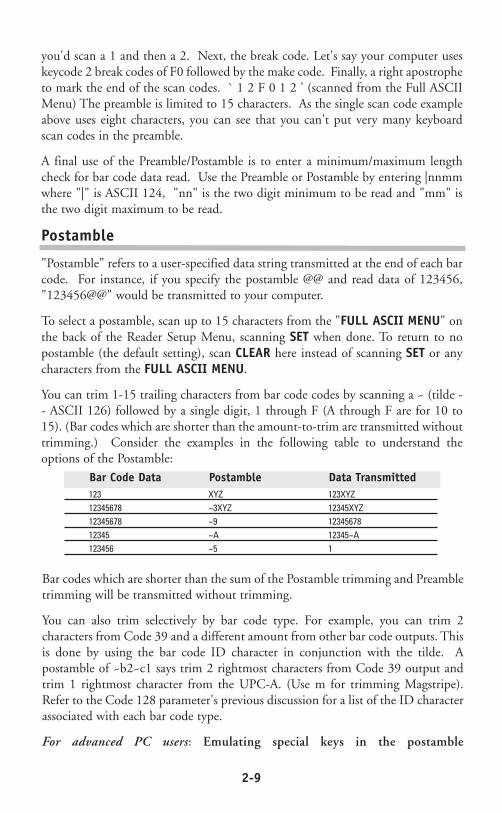
Postamble
"Postamble" refers to a user-specified data string transmitted at the end of each barcode. For instance, if you specify the postamble @@ and read data of 123456,"123456@@" would be transmitted to your computer.
To select a postamble, scan up to 15 characters from the "FULL ASCII MENU" onthe back of the Reader Setup Menu, scanning SET when done. To return to nopostamble (the default setting), scan CLEAR here instead of scanning SET or anycharacters from the FULL ASCII MENU.
You can trim 1-15 trailing characters from bar code codes by scanning a ~ (tilde -- ASCII 126) followed by a single digit, 1 through F (A through F are for 10 to15). (Bar codes which are shorter than the amount-to-trim are transmitted withouttrimming.) Consider the examples in the following table to understand theoptions of the Postamble:
123 XYZ 123XYZ12345678 ~3XYZ 12345XYZ12345678 ~9 1234567812345 ~A 12345~A123456 ~5 1
Bar Code Data Postamble Data Transmitted
Bar codes which are shorter than the sum of the Postamble trimming and Preambletrimming will be transmitted without trimming.
You can also trim selectively by bar code type. For example, you can trim 2characters from Code 39 and a different amount from other bar code outputs. Thisis done by using the bar code ID character in conjunction with the tilde. Apostamble of ~b2~c1 says trim 2 rightmost characters from Code 39 output andtrim 1 rightmost character from the UPC-A. (Use m for trimming Magstripe).Refer to the Code 128 parameter's previous discussion for a list of the ID characterassociated with each bar code type.
For advanced PC users: Emulating special keys in the postamble

2-10
See the previous page's "emulating special keys in the preamble" section.
A final use of the Preamble/Postamble is to enter a minimum/maximum lengthcheck for bar code data read. Use the Preamble or Postamble by entering |nnmmwhere "|" is ASCII 124, "nn" is the two digit minimum to be read and "mm" isthe two digit maximum to be read.
Data Transmission Timing
None 0 Short 1Short Medium 2Medium 3Long 4
Timing does not apply to Mac ADB or any USB attachment.
Before trying this, try the "learned timing" discussed on page 12.
For Computer Interfaces 0,1,and 2, the WDP Reader can transmit bar code data atfive different rates. Most computers work at the fastest speed ("None"), but somesystems require slower rates. Try the "None" setting, and (when you're doneconfiguring it) try reading some codes. If you get partial or garbled reads, try othertiming settings to solve the problem. (The Mac needs no timing adjustments.) Tryeach timing rate (fast to slow); don't assume that if the slowest and fastest don'twork, the intermediate settings won't either. After each failing attempt at timingsetting, type "12" in the upper keyboard row to be sure the keyboard has not beenlocked or confused; if the "12" doesn't type correctly, reboot before trying a newtiming setting.
Reset
Don't scan Reset unless you're sure you want to restore the WDP Reader to itsdefault settings (as described on page 7), erasing all changes you've made, becausethat's exactly what Reset will do.
MagStripe
None (or triggered Integrated CCD) 0Track 1 (or triggerless Integrated CCD) 1Track 2 2Track 3 3Dual Track Scanner,Output both only 4Dual Track Scanner,Output both or 2 only 5Track 1 or 3 Only on Dual Track Scanner 6Track 2 only output on Dual Track Scanner 7Track 1&2&3 Scanner, all 3 or 1&2 only 8Track 1&2&3 Scanner, all 3 or 1 only 9Caps Lock Off (just for MagStripe) ECaps Lock On (upper case alpha for mag) F
2-11
Use None (the default), if you don't have a MagStripe scanner. If you have a single-track scanner, use 1, 2 or 3 to match its track. If you have a dual-track scanner andwant to read both tracks, use 4 for tracks 1 and 2, or 5 for 2 and 3.
Use 6, 7 or 8 if you have a dual-track scanner but want to read only track 1, 2 or3 respectively.
For all Driver's licenses,(including California) use 8 or 9. See page 21 for moreinformation on the MagStripe scanner.
Characters
This setup option allows you to output ASCII characters different from the onesscanned. (Don't use this option to configure the WDP Reader for your non-USkeyboard -- instead, use the Keyboard Country option described below.)
For example: Suppose you want the WDP Reader to output a hex 92 characterevery time you scan a 1 (hex 31); you want to remap hex 31 to hex 92, (If you'reusing 8 data bits, output of 80-F8 codes is possible.) Your Full ASCII Menu hasASCII and hex values for the 128 characters.
1) Scan the Start Setup Bar Code
2) Scan the Characters Bar Code on the Setup Sheet.
3) Scan 3 1 and 9 2 to output hex 92 when reading a "1".
4) Scan up to 7 other pairs of character reassignments.
5) Scan Set when complete.
6) Scan End Setup to exit setup mode.
You can also eliminate characters by reassigning hex codes to FF. For example, tostrip all $ (dollar sign) characters from transmission, you would follow the aboveinstructions and scan 2 4 F F in step 3.
Magstripe output is frequently required to be changed to conform to some specificsoftware package's requirement. For example, you might want to change the = and^ separator characters to spaces or CRs. Between trimming and replacement, youshould be able to reformat the Magstripe output to conform to most requirements.
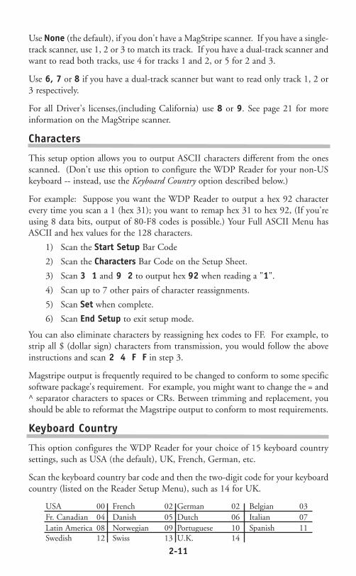
Keyboard Country
This option configures the WDP Reader for your choice of 15 keyboard countrysettings, such as USA (the default), UK, French, German, etc.
Scan the keyboard country bar code and then the two-digit code for your keyboardcountry (listed on the Reader Setup Menu), such as 14 for UK.
USA 00 French 02 German 02 Belgian 03Fr. Canadian 04 Danish 05 Dutch 06 Italian 07Latin America 08 Norwegian 09 Portuguese 10 Spanish 11Swedish 12 Swiss 13 U.K. 14

2-12
Terminator Characters
Enter (carriage return) 0None 1Tab 2
Depending on your application, you may wish the WDP Reader to transmit barcode data to your computer with an Enter (carriage return), a Tab at the end, orwith no extra terminating character at all.
If you need a terminator character other than CR or HT (such as LF for UNIX),you can get it by specifying None here and then selecting your desired terminatorcharacter(s) through the Postamble specification.
2-13
Testing the WDP reader with your computerWindows and Mac users should use the Notepad or a text editor so that the scanned testdata will be "typed" on the screen where you can see it. Similarly, DOS users should scanat the DOS prompt or while in a text editor.
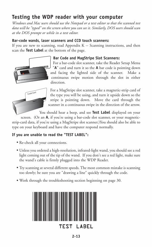
Bar-code wands, laser scanners and CCD touch scanners:If you are new to scanning, read Appendix K -- Scanning instructions, and thenscan the Test Label at the bottom of the page.
Bar Code and MagStripe Slot Scanners:For a bar-code slot scanner, take the Reader Setup Menu"A" card and turn it so the A bar code is pointing down
and facing the lighted side of the scanner. Make acontinuous swipe motion through the slot in eitherdirection.
For a MagStripe slot scanner, take a magnetic-strip card ofthe type you will be using, and turn it upside down so thestripe is pointing down. Move the card through the
scanner in a continuous swipe in the direction of the arrow.
You should hear a beep, and see Test Label displayed on yourscreen. (Or an A, if you're using a bar-code slot scanner, or your magnetic-
strip-card data, if you're using a MagStripe slot scanner.)You should also be able totype on your keyboard and have the computer respond normally.
If you are unable to read the "TEST LABEL":
Re-check all your connections.
Unless you ordered a high-resolution, infrared-light wand, you should see a redlight coming out of the tip of the wand. If you don't see a red light, make surethe wand's cable is firmly plugged into the WDP Reader.
Try scanning at several different speeds. The most common mistake is scanningtoo slowly; be sure you are "drawing a line" quickly through the code.
Work through the troubleshooting section beginning on page 30.
••
••
••
••
TTEESSTT LLAABBEELL
Credit Card
������������
3-1
Chapter 4
Scanners and Scanning TechniqueWandsMatching your wand to your bar code typeThe WDP Reader comes with a low, medium or high-resolution bar code wand, ora medium-resolution wand specially designed to read through plastic or glass,depending on your application. The number and letters on your wand's cableidentify its resolution and the type of light it uses -- visible red or infrared (invisible):
10 MILRED Low-resolution visible-light8 MILRED Medium-resolution visible-light6 MILRED High-resolution visible-light6 MILIR High-resolution infrared-light
These are the five types of wands and their associated characteristics:
Low-resolution visible-light wandThis is a low-resolution visible-red LED wand designed specifically for dot-matrixprinted bar codes. It reads any low or medium-resolution bar code printed by anytechnology, but can't easily read high density codes.
Medium-resolution visible-light wandA versatile, general-purpose medium-resolution visible-red LED wand which readswell-printed dot-matrix bar codes and high-density codes up to 10 cpi for Code 39.It reads well-printed dot-matrix codes with the same high read rate as the low-resolution wand. With poorly-printed codes, however, the low-resolution wandsignificantly outperforms it.
Refocused medium-resolution infrared-light wandThis is a medium-resolution infrared (invisible) light wand designed to read throughplastic or glass 1/100" (.025 mm) to 1/4" (6.35 mm) thick. This is especially usefulfor applications such as reading compact disks with the bar codes under the cases. Barcodes must be printed with infrared-quality ink. Bar codes printed on thermalprinters (not thermal-transfer printers) are often unreadable to infrared light wands.There is an additional charge of $60 for this wand.
High-resolution visible-light wandThis is a high-resolution visible red light wand designed to read high-density barcodes up to 13 cpi for Code 39. It can also read any well-printed dot-matrix or otherlower-density codes, providing there are no voids (white spots in the bars) in thecodes.
High-resolution infrared-light wandThis high-resolution infrared-light wand is designed to read high-density bar codes up to13 cpi for Code 39. It also reads well-printed dot-matrix or other lower-density codes,providing they're printed with infrared-quality ink (bar codes printed on thermal printersare often unreadable to infrared scanners) and don't have any voids (white spots in the bars).
••••••••

3-2
Wand Scanning Technique
Using the illustration as a guide, follow these tips for proper scanning with a wand:
1Hold the "wand" as you would a pencil,lightly placing your fingers around the wand.If you do not see a red light at the tip of the
wand, check to make sure that you are using aVISIBLE light wand, not an INFRARED lightwand. Infrared wands show no light at the tip ofthe wand.
2Your scanning should start in the whitespace about ¼" to the left or right of the barcode. This area is called the "quiet zone". If
you are reading a UPC code with a supplement,you MUST scan from left to right; otherwise, youcan scan from either direction.
3You should be holding the wand as if it werea pencil, approximately 30 degrees from perpendicular. Some bar codes,especially those that are high density, may require that you adjust the angle of
the wand to be almost perpendicular to the bar code. Starting in the "quiet zone",quickly and lightly draw an imaginary line through the entire bar code, ending withinthe ¼" "quiet zone" at the other end of the bar code. DO NOT scan slowly or pressdown hard with the wand - neither one will make it easier to read your bar code.
4Never stop in the middle of the bar code. Pass the wand smoothly acrossthe bar code, stopping only when you have reached the "quiet zone" at theother end.
5Do not move the wand tip above or below the lines of the bar code. Keep thewand tip within the confines of the bar code during the entire scan; the wholepoint is to draw as straight a line as possible through the middle of the bar code.
To practice scanning, go to the DOS prompt or open up Notepad or a similarprogram in Windows or on the Macintosh. Use the Test Label on the next page andthe technique illustration above to practice scanning with your wand. You shouldhear an audible beep and see TEST LABEL displayed on computer screen afterevery scan. If you do not see TEST LABEL, check your technique, especially theangle and speed of the scan.
30
3-3
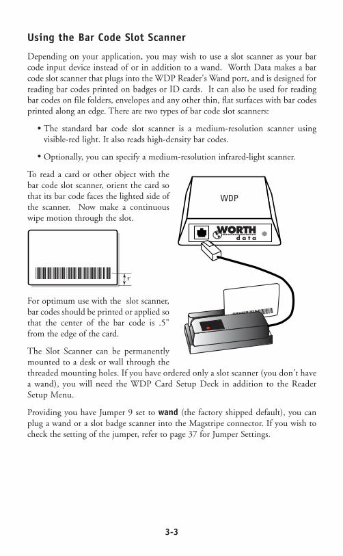
Using the Bar Code Slot Scanner
Depending on your application, you may wish to use a slot scanner as your barcode input device instead of or in addition to a wand. Worth Data makes a barcode slot scanner that plugs into the WDP Reader's Wand port, and is designed forreading bar codes printed on badges or ID cards. It can also be used for readingbar codes on file folders, envelopes and any other thin, flat surfaces with bar codesprinted along an edge. There are two types of bar code slot scanners:
The standard bar code slot scanner is a medium-resolution scanner usingvisible-red light. It also reads high-density bar codes.
Optionally, you can specify a medium-resolution infrared-light scanner.
To read a card or other object with thebar code slot scanner, orient the card sothat its bar code faces the lighted side ofthe scanner. Now make a continuouswipe motion through the slot.
For optimum use with the slot scanner,bar codes should be printed or applied sothat the center of the bar code is .5"from the edge of the card.
The Slot Scanner can be permanentlymounted to a desk or wall through thethreaded mounting holes. If you have ordered only a slot scanner (you don't havea wand), you will need the WDP Card Setup Deck in addition to the ReaderSetup Menu.
Providing you have Jumper 9 set to wand (the factory shipped default), you canplug a wand or a slot badge scanner into the Magstripe connector. If you wish tocheck the setting of the jumper, refer to page 37 for Jumper Settings.
••
••
������������
WDP
������������ .5"
3-4
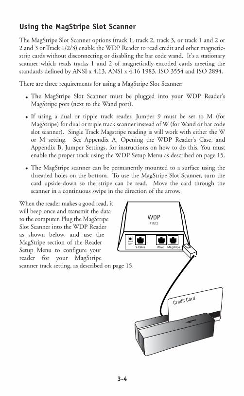
Using the MagStripe Slot Scanner
The MagStripe Slot Scanner options (track 1, track 2, track 3, or track 1 and 2 or2 and 3 or Track 1/2/3) enable the WDP Reader to read credit and other magnetic-strip cards without disconnecting or disabling the bar code wand. It's a stationaryscanner which reads tracks 1 and 2 of magnetically-encoded cards meeting thestandards defined by ANSI x 4.13, ANSI x 4.16 1983, ISO 3554 and ISO 2894.
There are three requirements for using a MagStripe Slot Scanner:
The MagStripe Slot Scanner must be plugged into your WDP Reader'sMagStripe port (next to the Wand port).
If using a dual or tipple track reader, Jumper 9 must be set to M (forMagStripe) for dual or triple track scanner instead of W (for Wand or bar codeslot scanner). Single Track Magstripe reading is will work with either the Wor M setting. See Appendix A, Opening the WDP Reader's Case, andAppendix B, Jumper Settings, for instructions on how to do this. You mustenable the proper track using the WDP Setup Menu as described on page 15.
The MagStripe scanner can be permanently mounted to a surface using thethreaded holes on the bottom. To use the MagStripe Slot Scanner, turn thecard upside-down so the stripe can be read. Move the card through thescanner in a continuous swipe in the direction of the arrow.
When the reader makes a good read, itwill beep once and transmit the datato the computer. Plug the MagStripeSlot Scanner into the WDP Readeras shown below, and use theMagStripe section of the ReaderSetup Menu to configure yourreader for your MagStripescanner track setting, as described on page 15.
••
••
••
WDP
Credit Card
PwrY-Cable MagstripeWand
P11/12
3-5
Laser and CCD Scanners
Wand scanners can satisfy most bar code reading needs. However, we also offerIntegrated Laser Wedge Readers and the Integrated CCD Wedge Reader (completeWDP Readers built into a laser scanner and CCD scanner) as well as laser andCCD scanners that plug directly into WDP Reader wand ports. Laser scanners addthese abilities to the WDP Reader:
Fast reading of difficult bar codes.
Reading bar codes from a distance: 1 to 21 inches with Worth Data' modelLZ200, up to 35 feet with the Symbol 3200ER, and typically 3 to 14 incheswith other laser scanners.
Reading moving objects, such as on an assembly line.
No-hands operation. Some scanners can be mounted to turn on automaticallywhen an object passes under them.
Reading through thick (up to five inches) glass or plastic laminates.
Reading curved surfaces, such as plastic bags of items.
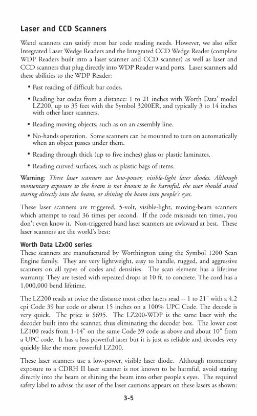
Warning: These laser scanners use low-power, visible-light laser diodes. Althoughmomentary exposure to the beam is not known to be harmful, the user should avoidstaring directly into the beam, or shining the beam into people's eyes.
These laser scanners are triggered, 5-volt, visible-light, moving-beam scannerswhich attempt to read 36 times per second. If the code misreads ten times, youdon't even know it. Non-triggered hand laser scanners are awkward at best. Theselaser scanners are the world's best:
Worth Data LZx00 seriesThese scanners are manufactured by Worthington using the Symbol 1200 ScanEngine family. They are very lightweight, easy to handle, rugged, and aggressivescanners on all types of codes and densities. The scan element has a lifetimewarranty. They are tested with repeated drops at 10 ft. to concrete. The cord has a1,000,000 bend lifetime.
The LZ200 reads at twice the distance most other lasers read -- 1 to 21" with a 4.2cpi Code 39 bar code or about 15 inches on a 100% UPC Code. The decode isvery quick. The price is $695. The LZ200-WDP is the same laser with thedecoder built into the scanner, thus eliminating the decoder box. The lower costLZ100 reads from 1-14" on the same Code 39 code as above and about 10" froma UPC code. It has a less powerful laser but it is just as reliable and decodes veryquickly like the more powerful LZ200.
These laser scanners use a low-power, visible laser diode. Although momentaryexposure to a CDRH II laser scanner is not known to be harmful, avoid staringdirectly into the beam or shining the beam into other people's eyes. The requiredsafety label to advise the user of the laser cautions appears on these lasers as shown:
••
••
••
••
••
••
3-6
Remember, even though momentary exposure to these low-power, visible-lightlasers is not known to be harmful, youmust never stare into the beam or aim it intoanyone's eyes. See the following pages for tips on solving problems with laser andCCD scanners and difficult codes.
The LZ100,LZ200,LZ100-WDP, and LZ200-WDP are covered by one or more of the following U.S. patents:
Patent#:4,360,798; 4,387,297; 4,460,120; 4,496,831; 4,593,186; 4,603,262; 4,607,156; 4,652,750; 4,673,805; 4,736,095; 4,816,660;4,845,350; 4,896,026; 4,897,532; 4,923,281; 4,933,538; 4,992,717; 5,015,833; 5,017,765; 5,021,641; 5,029,183; 5,047,617;5,103,461; 5,113,445; 5,140,144; 5,142,550; 5,149,950; 5,157,687; 5,168,148; 5,168,149; 5,180,904; 5,229,591; 5,230,088;5,235,167; 5,243,655; 5,247,162; 5,250,791; 5,250,792; 5,262,627; 5,280,163; 5,280,164; 5,280,498; 5,304,786; 5,304,788;5,321,246; 5,377,361; 5,367,151; 5,373,148; 5,378,882; 5,396,053; 5,396,055; 5,399,846; 5,404,081; 5,410,139; 5,410,140;5,142,198; 5,418,812; 5,420,411; 5,436,440; 5,444,231; 5,449,891; 5,449,893; 5,468,949; 5,479,000; 5,479,002; 5,479,441;5,504,322; 5,528,621; 5,532,469; 5,543,610; 5,545,889; 5,552,592; 5,578,810; 5,589,680; 5,612,531
A stand is available for all of the Worthington lasers which allows hands freereading of bar codes. Just before placing the scanner in the stand, scan the bar codeon the stand to set the laser into a automatic reading mode. When a bar code ispresented the narrow searching beam is turned on fully to read the bar codepresented. The stand is available in a mountable goose neck (S10) or in a freestanding version (S20). The stand can also be used with the F86 CCD Scannerand WDP-P16 Integrated CCD Reader. Below is a drawing showing how the Lx00Laser Scanner or the Lx00 WDP mounts into the stand with the weighted base.(The WDP P11/12 must have JP8 set to L for the stand mode to work correctly.See Appendix B.)
ACHTUNG LASERSTRAHL, LASERCLASSE 2, NICHT IN DEN STRAHL BLICKEN.
LUMIERE LASER – NE PAS REGARDERDANS LE FAISCEAU APPAREIL A LASER DE CLASSE 2.
CAUTION – LASER LIGHT WHEN OPEN,DO NOT STARE INTO BEAM.
IEC CLASS 2 LASER PRODUCT.680 nM, 1 mW LASER. IEC 825-1:1933/EN60825-1:1994
AVOID EXPOSURE LASER LIGHT IS EMITTED FROM THIS APERTURE
680 nm LASER • 1.0 MILLIWATT MAX OUTPUTCLASS II LASER PRODUCT
LASER LIGHT - DO NOT STARE INTO BEAM
CAUTION
product complies with 21 cfr chapter 1, subchapter j. no user servicable parts.opening voids warranty
DANGER Ð LASER LIGHT WHEN OPEN. AVOID DIRECT EYE EXPOSURE
SEE MANUAL FOR ADDITIONAL PATENT LISTINGS
Worthington Data Solutions ¥ Santa Cruz, CA 95060

3-7
CCD Scanners
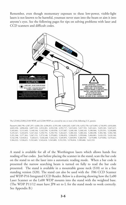
The F86 CCD Scanner or the WDP P16 Integrated CCD Reader can also mountin the stand, but the bar code must be presented within 0-4" of the scanner. Thesequick, durable units(F86 CCD Scanner) work like a laser, but with more limitedrange. Just aim the scanner at the bar code and by aligning the top of the ratherwide beam so that it is within the bar code, pull the trigger and a read occursinstantly. There are 50 scan attempts per second made. This CCD scanner can alsobe programmed for triggerless scanning on the WDP by scanning the bar codebelow:
STAND ON/OFF
STAND ON/OFF
3-8
The Integrated CCD Wedge Reader is a complete WDP Reader built into the F86CCD Scanner. Just plug it in between your computer and keyboard and you'reready to go. It works with any PC keyboard-compatible computer and allMacintosh models.
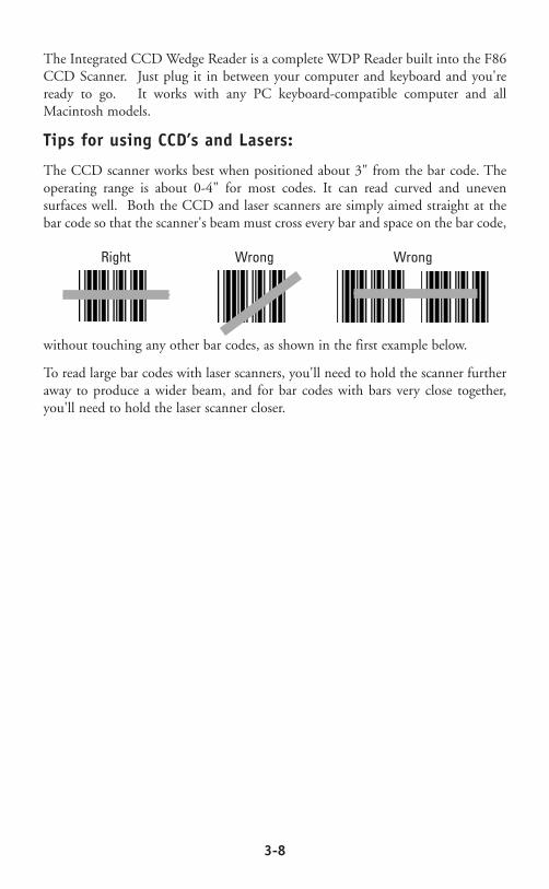
Tips for using CCD’s and Lasers:
The CCD scanner works best when positioned about 3" from the bar code. Theoperating range is about 0-4" for most codes. It can read curved and unevensurfaces well. Both the CCD and laser scanners are simply aimed straight at thebar code so that the scanner's beam must cross every bar and space on the bar code,
without touching any other bar codes, as shown in the first example below.
To read large bar codes with laser scanners, you'll need to hold the scanner furtheraway to produce a wider beam, and for bar codes with bars very close together,you'll need to hold the laser scanner closer.
Right Wrong Wrong
3-9
Laser scanner options:
"Double-scan checking": To minimize the possibility of misreads with verypoorly printed bar codes or when reading through windshields, you have theoption of forcing the WDP to keep reading until it gets two results that are exactlythe same. This "double scan checking" takes a little longer, but it will eliminatemisreads. To activate double scan checking:
Scan Start SetupScan Code 39Scan E to enable double scan checking.Scan End Setup
To disable double scan checking, scan F instead of E.
4-second beam: Another option with problem reading conditions is to increasethe length of the time the scanner attempts to read, from the default 2-second beamto a 4-second beam. This would be very helpful using long range scanners whichneeds additional aiming or scanning time. To select the 4-second beam:
Scan Start SetupScan 2 of 5Scan F to select the 4-second beamScan End Setup
To return to the default 2-second beam, scan E instead of F.
Continuous Scanning Option for the CCD scanner: Sometimes it is desirable toread sheets or lists of bar codes without having to activate the trigger before eachread. To activate the CCD continuous scanning:
Scan Start SetupScan Computer InterfaceScan B to select continuous scanningScan End Setup
To disable continuous scanning, repeat the above, substituting C for B.
To use continuous scanning with a laser scanner, scan D; however, you will have tohold down the trigger while scanning. In either case, if you want to read the samebar code twice in succession, you will need to release the trigger and pull it again.
Small quiet zones: Although we recommend quiet zones (white space on eitherside of a bar code) of at least 0.25", this option lets the laser and CCD scannersread bar codes with less than 0.2" quiet zones, the only drawback being anextremely small increase in the possibility of substitution errors.
Scan Start SetupScan Computer Interface Scan F to select small quiet zonesScan End Setup
To return to normal quiet zones, repeat the above, substituting E for F.
4-1
Chapter 4
Special Features
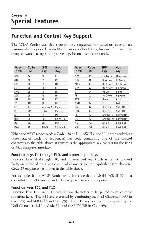
Function and Control Key SupportThe WDP Reader can also transmit key sequences for function, control, alt(command and option keys on Macs), cursor and shift keys, for ease of use with themany software packages using these keys for menus or commands.
When the WDP reader reads a Code 128 or Full-ASCII Code 39 (or the equivalenttwo-character Code 39 sequences) bar code containing one of the controlcharacters in the table above, it transmits the appropriate key code(s) for the IBMor Mac computer interface.
Function keys F1 through F10, and numeric-pad keysFunction keys F1 through F10, and numeric-pad keys (such as Left Arrow andDel), are encoded by a single control character (or the equivalent two-characterCode 39 sequences) as shown in the table above.
For example, if the WDP Reader reads bar code data of SOH (ASCII 001 -- acontrol-A), it will transmit an F1 key sequence to your computer.
Function keys F11 and F12Function keys F11 and F12 require two characters to be paired to make thesefunctions keys. The F11 key is created by combining the Null Character (%U inCode 39) and SOH ($A in Code 39). The F12 key is created by combining theNull Character (%U in Code 39) and the STX ($B in Code 39).
SOH $A F1 F1STX $B F2 F2ETX $C F3 F3EOT $D F4 F4ENQ $E F5 F5ACK $F F6 F6BEL $G F7 F7SO $N F8 F8LF $J Numpad 5 EnterCR $M Enter ReturnSI $O F9 F9DLE $P F10 Cmnd OnDC1 $Q Del DelDC2 $R Insert Cmnd Off
DC3 $S Lft Arrow Lft ArrowDC4 $T Rt Arrow Rt ArrowNAK $U Dn Arrow Dn ArrowSYN $V Up Arrow Up ArrowVT $K Pg Up Pg UpFF $L Pg Down Pg DownETB $W Home HomeCAN $X End EndEM $Y Shift ON Shift ONSUB $Z Shift OFF Shift OFFFS %B Control On Control OnGS %C Control Off Control OffRS %D Alt On Option OnUS %E Alt Off Option Off
FA or Code IBM MacC128 39 Key Key
FA or Code IBM MacC128 39 Key Key

4-2
Shift, Ctrl and Alt keysShift, Ctrl and Alt keys require three sequences
1) The ON code generated when the Shift, Ctrl or Alt key is pressed.
2) The other key to be used in conjunction with the Shift, Ctrl or Alt key.
3) The OFF code generated when the Shift, Ctrl or Alt key is released.
For example, to properly encode a bar code sequence for Ctrl-C, you would createa bar code of Ctrl ON, C, and Ctrl OFF (control character FS, C and controlcharacter GS).
Windows KeyThe Windows key on a Windows keyboard is transmitted by scanning bar codes%UC for Windows On (pressing down) and %UD for Windows Off (releasing thekey).
Macintosh Command and Option Keys on USBWhen you have a WDP Reader attached to a Macintosh Computer's USB port, toemulate the Command key, you use the Windows key On/Off bar codes (%UC -Command On and %UD - for Command Off ) the Alt Key On/Off (%D forOption On and %E for Option Off ).
If you have an older WDS Reader (before 6/99), you can also imitate theCommand Key by keycodes in the Preamble/Postable. To transmit Command N would be:`E01F'N`E0F01F'
Transmitting any ASCII character using its 3-digit ASCII codeYou can also transmit any ASCII character from 000 to 255 by emulating the IBMtechnique of typing a character's ASCII number on the numeric pad while holdingdown the Alt key.
For example, to transmit ASCII 250, you would create a bar code of Alt On, DownArrow (2 on the numeric pad), Numpad 5, Insert (0 on the numeric pad) and AltOFF (control character RS, control character NAK, control character LF, controlcharacter DC2 and control character US).

4-3
Accumulate ModeAccumulate Mode is an option (which can be enabled or disabled using the ReaderSetup Menu's Code 39 section) allowing the reader to accumulate multiple barcodes in its buffer, then transmit them to the computer as if they had been a singlebar code. This is useful for entering quantities and other variable data.
It works with Code 39 only, and can't be used with a check digit. When the readerreads a bar code with a leading space, it beeps and buffers the data withouttransmission. It continues to read and buffer bar codes (up to 40 characters) untilit reads a bar code without a leading space. Then the entire buffer (including thatlast code) is transmitted as one long bar code. A bar code of a double minus (--)sign clears the buffer. Scanning a backspace code ($H) backspaces in Full ASCIImode. A handy code for Enter (as seen on the "Barpad" below) is a Start/Stop only.(No data.)
This numeric "Barpad" illustrates Accumulate Mode. Scan 5, 3, 8, and Enter.The reader transmits a single message of 538.
0 1 2
3 4 5
6 7 8
9 Clear Backspace
CR Enter
5-1
Chapter 5
Troubleshooting
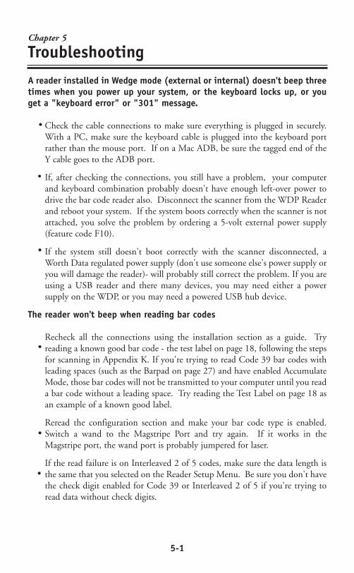
A reader installed in Wedge mode (external or internal) doesn't beep threetimes when you power up your system, or the keyboard locks up, or youget a "keyboard error" or "301" message.
Check the cable connections to make sure everything is plugged in securely.With a PC, make sure the keyboard cable is plugged into the keyboard portrather than the mouse port. If on a Mac ADB, be sure the tagged end of theY cable goes to the ADB port.
If, after checking the connections, you still have a problem, your computerand keyboard combination probably doesn't have enough left-over power todrive the bar code reader also. Disconnect the scanner from the WDP Readerand reboot your system. If the system boots correctly when the scanner is notattached, you solve the problem by ordering a 5-volt external power supply(feature code F10).
If the system still doesn't boot correctly with the scanner disconnected, aWorth Data regulated power supply (don't use someone else's power supply oryou will damage the reader)- will probably still correct the problem. If you areusing a USB reader and there many devices, you may need either a powersupply on the WDP, or you may need a powered USB hub device.
The reader won't beep when reading bar codes
Recheck all the connections using the installation section as a guide. Tryreading a known good bar code - the test label on page 18, following the stepsfor scanning in Appendix K. If you're trying to read Code 39 bar codes withleading spaces (such as the Barpad on page 27) and have enabled AccumulateMode, those bar codes will not be transmitted to your computer until you reada bar code without a leading space. Try reading the Test Label on page 18 asan example of a known good label.
Reread the configuration section and make your bar code type is enabled.Switch a wand to the Magstripe Port and try again. If it works in theMagstripe port, the wand port is probably jumpered for laser.
If the read failure is on Interleaved 2 of 5 codes, make sure the data length isthe same that you selected on the Reader Setup Menu. Be sure you don't havethe check digit enabled for Code 39 or Interleaved 2 of 5 if you're trying toread data without check digits.
••
••
••
••
••
••

5-2
Extra characters at the beginning or end of your bar code data
Clear the Preamble and Postamble.
Make sure you haven't enabled transmission of any start/stop characters,checksums, leading digits or terminator characters that you don't wanttransmitted. For UPC-E, select Compressed transmission if you don't want itpadded with extra zeros.
The reader transmits incorrect data to the screen
Reread page 12 and make sure you chose the proper Computer Interface.
If part of the data is correct and part missing, you need to tell the WDP Readerto transmit data at a different rate. First try Learned Timing on page 12, andif that doesn't work, resort to changing Data Transmission Timing on page 15.
If the reader is transmitting punctuation characters (!@#$%^&*) whenreading numeric bar codes, or transmitting letters in the wrong (upper/lower)case, you may have a Num Lock, Caps Lock, shift or timing problem. Checkyour keyboard to see if the Num Lock or Caps Lock keys have been activated.Finally, try "learned timing" (See Page 12) or changing your DataTransmission Timing (See page 15).
If you're using Code 39, read page 16 to see if you've set Caps Lock properlyfor your application. If your Code 39 bar codes include punctuationcharacters %, $, / or +, the reader is seeing them as part of Full-ASCII Code39 sequences. Using the Reader Setup Menu, disable Full ASCII Code 39.
Poor read rate
Try reading the test label on page 18 (following the scanning instructions inAppendix K) as an example of a known good bar code. Examine your barcodes to make sure they have dark bars, clearly defined bars and white spaces,and a "quiet zone" of at least 1/4 inch to the left and right. If the bars are grey,or so dark that they "bleed" into the white spaces, the person or organizationprinting them will need to adjust the printer or get a new ribbon or tonercartridge for it.
Carefully follow the scanning instructions Appendix K when reading any andall bar codes. As straightforward as scanning may seem, many people who callWorth Data with a complaint about poor read rate are simply not doing itcorrectly.
If you're using an infrared bar code wand, be sure the bar codes you're tryingto read were printed with infrared-quality ink. Make sure you're using theright type of wand (see page 19) for the type of bar codes you're trying to read.
Pry the wand tip off; clean the inside with a soft, lint-free cloth. Carefully blowoff any debris from the red plastic lens.
••
••
••
••
••
••
••
••
••
••

5-3
Erratic or low read rates can also result with systems that supply unusually lowcurrent or voltage to the keyboard. To test for this, turn your system off,disconnect the keyboard from the "Y" cable, and turn it back on. Then tryreading the same bar codes. The system will probably be in a keyboard errorstate and not display the bar code data on the screen, but all you're interestedin is listening for the beeps that signify good reads. If the WDP Reader has amuch higher read rate without the keyboard attached, you can probably solvethe problem by using a Worth Data regulated 5-volt external power supply(F10).
Changing the volume of the WDP Reader's beeper:
First, you need to get to the WDP Reader's circuitboard. If you're using theReader in External Wedge mode, you'll need to remove the case, using theillustration on the next page as a guide. If it's mounted internally, you'll needto remove the cover to your computer's slot cabinet. Locate the volume-control potentiometer using the illustration below. Insert a small screwdriverinto the slot and gently turn it clockwise, to decrease the volume, orcounterclockwise, to increase it. A tiny fraction of a turn makes a bigdifference in volume.
5-volt power adapters for external wedge installation:
The 5-volt adapter (F10 for 110V, F11 for 220V, F14 for UK 220V, and F13for Australia 240V) is used to power the WDPs with separate decoder boxconfigurations where the computer supplies unusually-low voltage or currentto the keyboard. Do not plug in this adapter to a WDP Readers installed inbus mode. Connect the power adapter to the reader as shown below.
Don't use anything but a Worthington Data Solution's power supply or youwill probably damage the reader. The Worthington Data Solution's powersupply is regulated and has a specific polarity. Almost all other power suppliesare unregulated and will damage the WDP is used. Just because the connectorfits, don't use it.
••
••
••
••
A-1
Appendix A
Opening the WDP Case
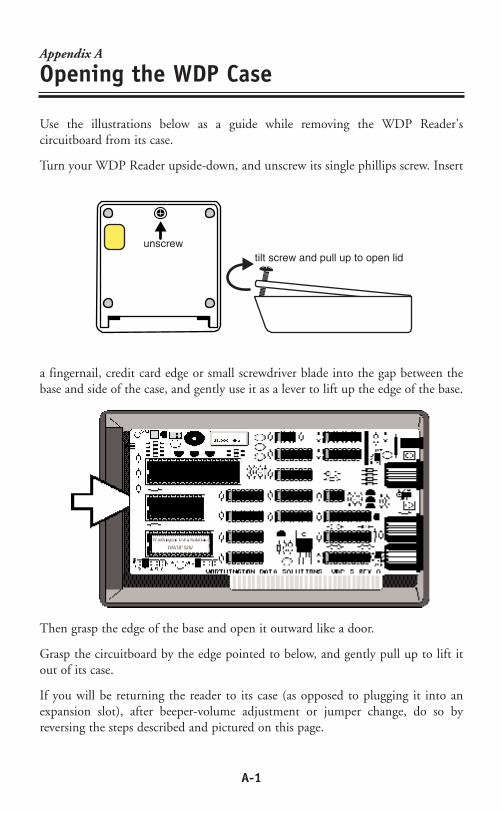
Use the illustrations below as a guide while removing the WDP Reader'scircuitboard from its case.
Turn your WDP Reader upside-down, and unscrew its single phillips screw. Insert
a fingernail, credit card edge or small screwdriver blade into the gap between thebase and side of the case, and gently use it as a lever to lift up the edge of the base.
Then grasp the edge of the base and open it outward like a door.
Grasp the circuitboard by the edge pointed to below, and gently pull up to lift itout of its case.
If you will be returning the reader to its case (as opposed to plugging it into anexpansion slot), after beeper-volume adjustment or jumper change, do so byreversing the steps described and pictured on this page.
open outward like a door
tilt screw and pull up to open lidunscrew
B-1
Appendix B
ISA Internal Board Installation
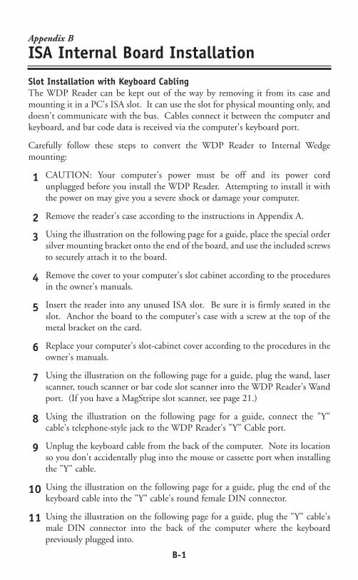
Slot Installation with Keyboard CablingThe WDP Reader can be kept out of the way by removing it from its case andmounting it in a PC's ISA slot. It can use the slot for physical mounting only, anddoesn't communicate with the bus. Cables connect it between the computer andkeyboard, and bar code data is received via the computer's keyboard port.
Carefully follow these steps to convert the WDP Reader to Internal Wedgemounting:
CAUTION: Your computer's power must be off and its power cordunplugged before you install the WDP Reader. Attempting to install it withthe power on may give you a severe shock or damage your computer.
Remove the reader's case according to the instructions in Appendix A.
Using the illustration on the following page for a guide, place the special ordersilver mounting bracket onto the end of the board, and use the included screwsto securely attach it to the board.
Remove the cover to your computer's slot cabinet according to the proceduresin the owner's manuals.
Insert the reader into any unused ISA slot. Be sure it is firmly seated in theslot. Anchor the board to the computer's case with a screw at the top of themetal bracket on the card.
Replace your computer's slot-cabinet cover according to the procedures in theowner's manuals.
Using the illustration on the following page for a guide, plug the wand, laserscanner, touch scanner or bar code slot scanner into the WDP Reader's Wandport. (If you have a MagStripe slot scanner, see page 21.)
Using the illustration on the following page for a guide, connect the "Y"cable's telephone-style jack to the WDP Reader's "Y" Cable port.
Unplug the keyboard cable from the back of the computer. Note its locationso you don't accidentally plug into the mouse or cassette port when installingthe "Y" cable.
Using the illustration on the following page for a guide, plug the end of thekeyboard cable into the "Y" cable's round female DIN connector.
Using the illustration on the following page for a guide, plug the "Y" cable'smale DIN connector into the back of the computer where the keyboardpreviously plugged into.
1
2
3
4
5
6
7
8
9
10
11

B-2
If you have a laser scanner, CCD scanner or bar code slot scanner, it will plug intothe wand port instead of the wand. (If you have a MagStripe slot scanner, see page21 for its installation instructions.) Be sure to store the WDP Reader's case in a safeplace: If you need the slot in the future, or upgrade to a system without PC-styleexpansion slots, you can easily replace the reader in its case for external mounting.
Now turn to page 7 to configure the WDP Reader.
The connections for Internal Wedge installation on a PC should be as shownbelow.
B-3
Slot Installation with Bus CommunicationFor computers running DOS, the internal WDP Reader can be mounted in anyunused ISA slot and jumpered to communicate with the bus directly. Internal Businstallation is normally a factory-special order (WDP Model P31/32) whichincludes BusKey software but no reader case or Velcro for mounting the case.Because the WDP Reader is not physically connected to the keyboard, it requiresthe program BusKey to read bar code data from the bus and place it into thekeyboard buffer.
See Appendix C for the jumper settings (JP4,JP5, and JP7) necessary to convert theWDP reader board to communicate directly with the bus.
The DOS program BusKey is used only when the WDP Reader is installed inInternal Bus mode. BusKey is a memory-resident program (TSR) that works in thebackground to read bar code data from the bus and place it into the keyboardbuffer, making it look to your computer and software as if the data had been typedat the keyboard. Most people will want to put BusKey in their AUTOEXEC.BATfile for automatic loading at boot time.
Installing BusKeyTo copy BusKey onto your system, simply use the DOS COPY command. Forinstance, to copy BusKey onto hard disk C:, place the BusKey distribution disketteinto drive A, log into the hard disk directory you want to install BusKey in, and atthe C> prompt type:
Copy A:BusKey.Com /v
BusKey ParametersWhen you run BusKey, you need to give it parameters specifying the interrupt andport address you've set the WDP Reader to. If you're not sure of these, go toAppendix C and read about setting the interrupt number and port address. Thesyntax is:
BusKey P=ppp I=i
where ppp equals the port address in hex, and i equals the interrupt number. Forexample, if you've set the WDP Reader to port 240 and interrupt 5, you'd startBusKey like this:
BusKey P=240 I=5
If you run BusKey with no parameters, it will use the default settings of p o r t220 and interrupt 3, the equivalent of BusKey P=220 I=3 typed at the DOSprompt.
See Appendix C for the jumper settings (JP4,JP5, and JP7) necessary to convert theWDP reader board to communicate directly with the bus.

C-1
Appendix C
Jumper Settings
Your WDP Reader is shipped with its jumpers set to match the configuration(scanner type, interface method, etc.) you ordered. Why might you need/want tocheck or change jumper settings?
If you change your scanner type, or install a second scanning device, you mayneed to change some jumper settings.
If you're going to install the WDP Reader in Bus Interface mode, you mayneed to change the Interrupt Number and Port Address jumpers.
If your WDP Reader or scanner doesn't power up correctly, you should makesure the WDP has the correct jumper settings for your configuration.
Open the WDP Reader's case using the instructions in Appendix A.
Interrupt Number jumper JP4, the Interrupt Number jumper:The WDP Reader in Bus Interface mode can use any one of interrupts 2 though 6.The default is interrupt 3. Go through the list below to determine which interruptsare not already in use in your system, and choose one of those. If all interrupts arealready in use, you'll either have to free one up (by disabling COM2 or LPT2 onyour computer, for example) or use the WDP Reader in wedge mode rather thanbus mode.
If your system has any real-time clocks, network boards, bus mice, tape controllersor other add-on devices installed, they may be using some of these interrupts. Ifyou have any of these in your system, compare their switch settings to your manualsto see what interrupts they're using.
Interrupt 2: Don't use this interrupt if you have an AT, 386 or 486 system, an EGA, or an IBM network adapter.
Interrupt 3: This interrupt is usually used by COM2, the second serial port. If you don't have a COM2, or an internal modem or other device set to COM2, you should be able to use it.
Interrupt 4: This interrupt is usually used by COM1, the first serial port. If you don't have a COM1, or an internal modem or other device set to COM1, you should be able to use it.
Interrupt 5: This interrupt is used by the hard disk on a PC or XT system, and LPT2, the second parallel port, on an AT system. You can use it if you have a floppy-only PC or XT system, or an AT system with onlyone parallel port.
Interrupt 6: This interrupt is used by the floppy diskette drive controller.
•
•
•
C-2
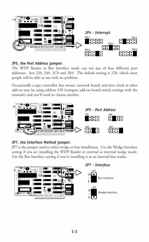
JP5, the Port Address jumper:The WDP Reader in Bus Interface mode can use any of four different portaddresses: hex 220, 240, 2C0 and 2E0. The default setting is 220, which mostpeople will be able to use with no problem.
Occasionally a tape controller, bus mouse, network board, real-time clock or otheradd-on may be using address 220 (compare add-on board switch settings with themanuals) and you'll need to choose another.
IRQ 2
IRQ 5
IRQ 4
IRQ 3
IRQ 6
JP4 - Interrupt
220 240
2C0 2E0
JP5 - Port Address
JP7, the Interface Method jumper:JP7 is the jumper used to select wedge or bus installation. Use the Wedge Interfacesetting if you are installing the WDP Reader in external or internal wedge mode.Use the Bus Interface setting if you're installing it as an internal bus reader.
JP7
JP7
W /B
W /B
Bus Interface
Wedge Interface
JP7 - Interface
C-3
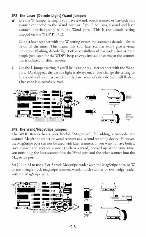
JP8, the Laser (Decode Light)/Wand jumper:Use the W jumper setting if you have a wand, touch scanner or bar-code slotscanner connected to the Wand port, or if you'll be using a wand and laserscanner interchangeably with the Wand port. This is the default settingshipped on the WDP P11/12.
Using a laser scanner with the W setting causes the scanner's decode light tobe on all the time. This means that your laser scanner won't give a visualindication (flashing decode light) of successfully-read bar codes, but as mostpeople just listen for the WDP's beep anyway instead of staring at the scanner,this is unlikely to affect anyone.
Use the L jumper setting if you'll be using only a laser scanner with the Wandport. (As shipped, the decode light is always on. If you change the setting toL, a wand will no longer work but the laser scanner's decode light will flash asa bar code is successfully read.
W
L
JP8
JP8
L / W
L / W
Wand Scanner
Laser ScannerDecode Light
JP9, the Wand/Magstripe jumper:The WDP Reader has a port labeled "MagStripe", for adding a bar-code slotscanner, MagStripe reader or wand scanner as a second scanning device. However,the MagStripe port can not be used with laser scanners. If you want to have both alaser scanner and another scanner (such as a wand) hooked up at the same time,you must plug the laser scanner into the Wand post and the other scanner into theMagStripe port.
Set JP9 to M to use a 2 or 3 track Magstripe reader with the MagStripe port, or Wto use a single track magstripe scanner, wand, touch scanner or slot-badge readerwith the MagStripe port.
JP9
JP9
W / M
W / M
D-1
Appendix D
Specifications for Code 39
Code 39 (or Code 3 of 9) is the de facto standard ofnon-retail American industry. It is widely used in theautomotive industry (AIAG specifications) as well as ingovernment and military applications (LOGMARSspecifications). Code 39 is flexible, features a large
character set, variable data length and density, and bi-directional readability. Code39 is extremely accurate; substitution errors are almost nonexistent. Its characterset consists of numbers 0 through 9, upper case A-Z, and characters Space, $, %. /+ and -.
The name "Code 39" comes from both the fact that its character set originallycontained 39 characters (it now has 43) and from its structure. Each character isformed of three wide and six narrow elements, made up of five bars and four spaces.Code 39's density can vary from a low of .75 characters per inch (cpi) to a high of9.4 cpi. There should be a ¼" "quiet zone" (white space) to the left and right ofthe bar code. Code 39 uses an asterisk (*) as a start and stop character. Thischaracter must precede and follow the data in the bar code. The WDP gives youthe option of transmitting or not transmitting these characters when the bar codeis read.
Exact specifications for Code 39 and other bar code symbologies can be obtainedfrom ANSI at the address below:
American National Standards InstituteCustomer Service11 West 42nd St.
New York, NY 10036http://web.ansi.org
document ANSI/AIM BC1-1995The cost is $36.
123ABC

D-2
Char Value Char Value Char Value Char Value0 0 B 11 M 22 X 331 1 C 12 N 23 Y 342 2 D 13 O 24 Z 353 3 E 14 P 25 - 364 4 F 15 Q 26 . 375 5 G 16 R 27 Space 386 6 H 17 S 28 $ 397 7 I 18 T 29 / 408 8 J 19 U 30 + 419 9 K 20 V 31 % 42A 10 L 21 W 32
Here is an example to illustrate how the check character is calculated for bar codedata of 123XYZ:
1. Take the sum of the values assigned to each character:
1 + 2 + 3 + 33 + 34 + 35 = 1081 2 3 X Y Z
2 Divide the sum by 43: (thus the name modulus 43)
108/43 = 2 with a Remainder of 22
3. Find the character corresponding with the remainder.
M (value 22) is the CHECK CHARACTER
The data becomes 123XYZM, with M added as the Mod-43 check character.
Mod 43 Check CharacterStandard Code 39 can be printed with a "Mod 43 Check Character". This Mod 43check character cannot be used with Full Ascii Code 39. The check character isderived by assigning a value to each character in the data to be bar coded from thetable as follows:
D-3
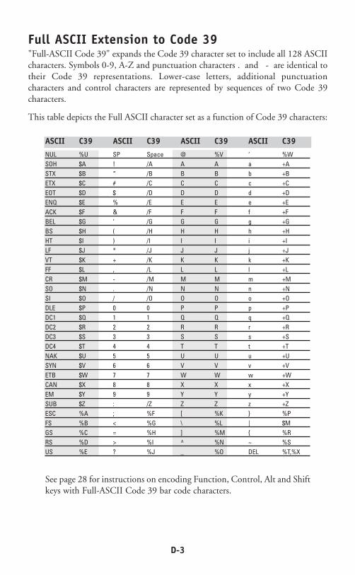
Full ASCII Extension to Code 39"Full-ASCII Code 39" expands the Code 39 character set to include all 128 ASCIIcharacters. Symbols 0-9, A-Z and punctuation characters . and - are identical totheir Code 39 representations. Lower-case letters, additional punctuationcharacters and control characters are represented by sequences of two Code 39characters.
This table depicts the Full ASCII character set as a function of Code 39 characters:
ASCII C39 ASCII C39 ASCII C39 ASCII C39
NUL %U SP Space @ %V ‘ %WSOH $A ! /A A A a +ASTX $B “ /B B B b +BETX $C # /C C C c +CEOT $D $ /D D D d +DENQ $E % /E E E e +EACK $F & /F F F f +FBEL $G ‘ /G G G g +GBS $H ( /H H H h +HHT $I ) /I I I i +ILF $J * /J J J j +JVT $K + /K K K k +KFF $L , /L L L l +LCR $M - /M M M m +MSO $N . /N N N n +NSI $O / /O O O o +ODLE $P 0 0 P P p +PDC1 $Q 1 1 Q Q q +QDC2 $R 2 2 R R r +RDC3 $S 3 3 S S s +SDC4 $T 4 4 T T t +TNAK $U 5 5 U U u +USYN $V 6 6 V V v +VETB $W 7 7 W W w +WCAN $X 8 8 X X x +XEM $Y 9 9 Y Y y +YSUB $Z : /Z Z Z z +ZESC %A ; %F [ %K } %PFS %B < %G \ %L | $MGS %C = %H ] %M { %RRS %D > %I ^ %N ~ %SUS %E ? %J _ %O DEL %T,%X
See page 28 for instructions on encoding Function, Control, Alt and Shiftkeys with Full-ASCII Code 39 bar code characters.

E-1
Appendix E
Codabar
Codabar is widely used in libraries, blood banks, thecotton industry and transportation industries. Its'character set consists of numbers 0 through 9, andpunctuation characters + . - / : and $. Symbols a, b, c,d, t, n, * and e are used as start and stop characters.Characters are constructed of four bars and three spaces.
Codabar is a numeric-only code, but different combinations of start and stopcharacters can be used to identify different types of labels. Codabar's variable datalength and extremely low error rate make for a versatile bar code.
Codabar start/stop transmissionThe Codabar section on the WDP Setup Menu lets you determine whetherCodabar start/stop characters are transmitted or not. If you are varying start/stopcharacters with different types of labels, you'll want to "Enable Stop/Start characterTransmission". Start/stop character transmission can also be helpful if you wantyour program to differentiate between data coming from the WDP reader and datacoming from the keyboard. If neither of these situations apply, you'll probablywant to disable it.
a29934567a
F-1
Appendix F
Code 128 Specifications
Code 128 is a very powerful bar code, combining anextensive character set and variable length withcompactness and error checking. The character set containsall 128 ASCII characters with each character made up ofthree bars and three spaces. Each element (bar or space)varies from one to four units in width, totaling 11 units of
width per character. Code 128 contains two levels of error checking:
Each character is checked for internal parity, and
The last character is a checksum.
Code 128 has three subsets, A, B and C. Subset A contains alphanumeric charactersand unprintable control characters, subset B contains alphanumeric characters plusprintable control characters and subset C contains only numeric characters and usesa 2-character encoding scheme to create a more compact bar code. Code 128 usesan internal Mod 103 check character that is not displayed by the bar code reader.Code 128 bar codes can be made up of only one subset or may be a combinationof several.
The Code 39 features of Accumulate Mode, Caps Lock ON and Caps lock OFF alsoapply to Code 128.
UCC-128/ EAN-128UCC-128/EAN-128 Code is a subset of Code 128 adopted by the UCC and EANcouncil's for use as a shipping label symbology. UCC/EAN-128 bar codes alwaysstart with a Function Code 1 character. In addition, all variable length fields areterminated by a Function Code 1 character unless they are the last field in the barcode.
The WDP outputs the following for the special function codes and start sequences:
]C1 Start C/Function Code 1
^] (GS) Function Code 1 as a variable string terminator
If MOD 10 UCC 128 is enabled, theWDP expects only 20 digit, numeric-only128 codes starting with a Function 1 character and terminating with a MOD 10Check Digit. This is to comply with the Uniform Code Council's Serial ShippingContainer Code specification. The Mod 10 Check digit is calculated the same asthe Interleaved 2 of 5 example in Appendix D. It is the MOD 10 check digit thatdistinguishes the Serial Shipping Container Code from other UCC /EAN 128 barcodes.
��
AB123456

F-2
MOD 10 UCC 128 is enabled by scanning the appropriate bar codes on theTriCoder Setup Menu or by keypad in the PROGRAMMING MODE "ChangeSetup" option. If MOD 10 UCC 128 is enabled, you will NOT be able to read astandard Code 128 bar code that does not have the Function 1 character and theMod 10 check character.
The UCC 128 specification is used extensively by the retail industry. If you have arequirement for a UCC 128 Serial Shipping Container bar code, be sure to followthe specification as closely as possible as many vendors will impose fines for non-conformance. For more information on UCC 128, contact the Uniform CodeCouncil at:
Uniform Product Code Council, Inc.8163 Old Yankee Road, Suite J
Dayton, Ohio 45458(513) 435-3870
Many of the specifications are available online at:
http://www.uc-council.org
UCC/EAN Code 128 Serial Shipping Container Code
G-1
Appendix G
Interleaved 2 of 5 Code
Interleaved 2 of 5 Code is a numeric-only, even-number-of-digits bar code. It is widely used in warehouse and industrialapplications. A combination of five elements, two wide andthree narrow represent each character. Odd-numberposition digits are encoded in the bars, even-number
positions in the spaces.
Interleaved 2 of 5 Code is so susceptible to partial scans being interpreted as validreads that we recommend at least one of the following safeguards:
Use one length of I 2 of 5 code. Using one length of data allows you to tell theTriCoder to look for one length of I 2 of 5 code only. By default, the TriCoderis set to look for a 6 digit I 2 of 5 code but you can set the length to somethingdifferent using the TriCoder Setup Menu. Setting the length to 00 digitsallows variable length bar codes scanning. If you must use the 00 setting, werecommend that you then use the "Minimum/Maximum" data length fieldwhen creating a program in the TriCoder to check each field for the properlength.
Use a check digit. Worth Data's LabelRIGHT printing program automaticallycalculates and prints a check digit upon request using the method below:
Interleaved 2 of 5 Mod 10 check digit calculation
1. Assume that the bar code data is 1987.
2. Starting with the least significant digit (in this case, a 7), label the digits alternatively even and odd.
7 - even8 - odd9 - even1 - odd
3. Take the sum of the odd digits:
8 + 1 = 9
4. Multiply the sum of the even digits by 3:
(7 + 9) x 3 = 48
�
�
123456

G-2
5. Add the results of steps 3 and 4:
9 + 48 = 57
6. Subtract the result of step 5 from the next highest multiple of 10:
60 - 57 = 3
7. The checksum becomes the low-order digit:
19873
8. Because the data now has an odd length, a leading zero is added, for the finalresult of:
019873

H-1
Appendix H
UPC Specifications
UPC symbols are found on almost all grocery productsand many other retail items. The UPC code most peopleare familiar with (UPC-A) is a fixed-length (12 digits)numeric only code, with the first digit controlled by UPCcoding assignments and the last digit a checksum. UPC-E and UPC-E1 are variations of the standard UPC-A
code. Each digit is constructed of two bars and two spaces. UPC has very precisestandards of code size, structure, and numbers to be used.
EAN is an international superset of UPC. EAN-13has 13 digits, with the first two digits representing acountry code. The final digit is, as with UPC, a checkdigit. EAN-8 is a shorter version on the EAN-13 codecontaining seven data digits and ending again with achecksum.
The exact UPC/EAN symbol specifications areavailable from:
Uniform Product Code Council, Inc.8163 Old Yankee Road, Suite J
Dayton, Ohio 45458(513) 435-3870
Specifications are also available via the internet at:
http://www.uc-council.org
Keep the following guidelines in mind when printing UPC bar codes:
If you plan to use a "supermarket-type" in-counter scanner to read the codes,specify a bar code height of at least .9" for an optimal first read rate.
Make it an early practice to observe the numbering conventions of the UPCCouncil. Do not label unmarked merchandise with a bar code whose numbersmay conflict with those already assigned. If products with these numbers arenot in your store now, they are likely to be in the future, causing conflicts inyour inventory system.
t56789rDEFG>W
+67L9NOrFG?@A?u
�
�
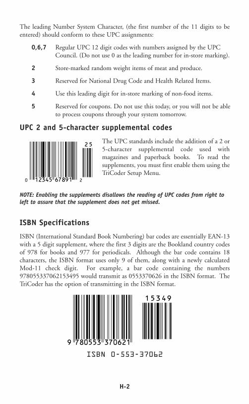
H-2
The leading Number System Character, (the first number of the 11 digits to beentered) should conform to these UPC assignments:
0,6,7 Regular UPC 12 digit codes with numbers assigned by the UPC Council. (Do not use 0 as the leading number for in-store marking).
2 Store-marked random weight items of meat and produce.
3 Reserved for National Drug Code and Health Related Items.
4 Use this leading digit for in-store marking of non-food items.
5 Reserved for coupons. Do not use this today, or you will not be able to process coupons through your system tomorrow.
UPC 2 and 5-character supplemental codes
The UPC standards include the addition of a 2 or5-character supplemental code used withmagazines and paperback books. To read thesupplements, you must first enable them using theTriCoder Setup Menu.
NOTE: Enabling the supplements disallows the reading of UPC codes from right toleft to assure that the supplement does not get missed.
ISBN Specifications
ISBN (International Standard Book Numbering) bar codes are essentially EAN-13with a 5 digit supplement, where the first 3 digits are the Bookland country codesof 978 for books and 977 for periodicals. Although the bar code contains 18characters, the ISBN format uses only 9 of them, along with a newly calculatedMod-11 check digit. For example, a bar code containing the numbers978055337062153495 would transmit as 0553370626 in the ISBN format. TheTriCoder has the option of transmitting in the ISBN format.
ISBN 0-553-37062
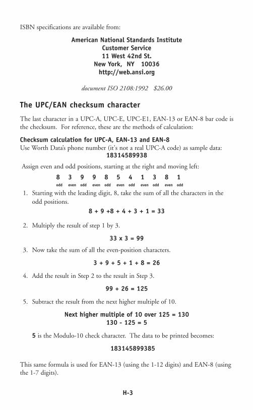
ISBN specifications are available from:
American National Standards InstituteCustomer Service11 West 42nd St.
New York, NY 10036http://web.ansi.org
document ISO 2108:1992 $26.00
The UPC/EAN checksum character
The last character in a UPC-A, UPC-E, UPC-E1, EAN-13 or EAN-8 bar code isthe checksum. For reference, these are the methods of calculation:
Checksum calculation for UPC-A, EAN-13 and EAN-8Use Worth Data’s phone number (it's not a real UPC-A code) as sample data:
18314589938
Assign even and odd positions, starting at the right and moving left:
8 3 9 9 8 5 4 1 3 8 1odd even odd even odd even odd even odd even odd
1. Starting with the leading digit, 8, take the sum of all the characters in the odd positions.
8 + 9 +8 + 4 + 3 + 1 = 33
2. Multiply the result of step 1 by 3.
33 x 3 = 99
3. Now take the sum of all the even-position characters.
3 + 9 + 5 + 1 + 8 = 26
4. Add the result in Step 2 to the result in Step 3.
99 + 26 = 125
5. Subtract the result from the next higher multiple of 10.
Next higher multiple of 10 over 125 = 130130 - 125 = 5
5 is the Modulo-10 check character. The data to be printed becomes:
183145899385
This same formula is used for EAN-13 (using the 1-12 digits) and EAN-8 (usingthe 1-7 digits).
H-3

H-4
Because the sample UPC-E code ends in a 6, the insertion digits 0000 are insertedat the sixth digit (insertion position 6):
1234500006
2. Add the Number System Character of 0 to the sample data:
01234500006
3. Use the UPC-A check digit calculation described in the previous section to produce a check digit as if it were a UPC-A code. The check digit for the sample data is:
5
4. The complete 8 digit code consists of the Number System Character, the original 6 digit code and the check digit:
01234565
If the code UPC-E data Insertion digits Insertion 10 digit codeends in: Position
0 abcde0 0 0 0 0 0 3 ab 0 0 0 0 0 cde1 abcde1 1 0 0 0 0 3 ab1 0 0 0 0 cde2 abcde2 2 0 0 0 0 3 ab2 0 0 0 0 cde3 abcde3 0 0 0 0 0 4 abc0 0 0 0 0 de4 abcde4 0 0 0 0 0 5 abcd 0 0 0 0 0 e5 abcde5 0 0 0 0 6 abcde 0 0 0 0 56 abcde6 0 0 0 0 6 abcde 0 0 0 0 67 abcde7 0 0 0 0 6 abcde 0 0 0 0 78 abcde8 0 0 0 0 6 abcde 0 0 0 0 89 abcde9 0 0 0 0 6 abcde 0 0 0 0 9
UPC-E Checksum CalculationUse the sample data of 123456 to demonstrate the UPC-E checksum calculation:
1. The 6 digit UPC-E code is converted to a 10-digit code, using an expansion scheme based on the sixth digit:

I-1
Appendix I
MSI/Plessey Specifications
Plessey is a variable length numeric only bar code. MSI Bar Code is a variablelength, numeric-only code with an automatically appended Modulus 10 checkdigit. MSI is sometimes called Modified Plessey Code. If the user specifies anadditional check digit, the MSI code can be 14 digits long, otherwise it has amaximum length of 13 characters. This is how the MSI check digit(s) arecalculated:
The MSI Mod 10 check digit is calculated as follows:
The example bar code data is:
82345
1. Form a number from the odd positions, starting in the units position.
835
2. Multiply the new number by 2
(835) x 2 = 1670
3. Add the digits of product
1 + 6 + 7 + 0 = 14
4. Add the even digits of the original number to the result in 3
2 + 4 + 14 = 20
5. Subtract the result from the next highest multiple of 10
20 - 20 = 0
6. New Check Digit
0
7. Data with check digit is:
823450

I-2
The MSI Mod 11 check digit is calculated as follows:
The example bar code data is:
943457842
1. Assign a checking factor to each number, starting with the units position of the number (in this example, the 2) up to the highest order position (the 9).Use checking factors of:
2,3,4,5,6,7,2,3,4,5,6,7...
2. Multiply the checking factor with its assigned number and add the products:
4 + 12 + 32 + 35 + 30 + 28 + 6 + 12 + 36 = 195
3. Divide the sum by 11
195/11 = 17 remainder 8
4. Subtract remainder from 11
11 - 8 = 3
5. New Check Digit
3(If the remainder is 10, no check digit is added.)
6. Data with check digit is:
943457823

J-1
Appendix J
Code 93 Specifications
Code 93 is variable length, continuous, bi-directional, compact code. Code 93 isan alphanumeric bar code which consists of 43 data characters (0-9,A-Z,$/+%.-and Space), 4 control characters, and a unique start/stop character. The entire setof 128 ASCII characters is represented in Code 93 using combinations of controlcharacters and data characters.
The control characters are a n d . Full ASCII 93 is createdby pairing these control characters with normal data characters. It is almostidentical to the pairings for Code 39; Code 39 uses $M to produce aCarriage Return (ASCII 13) character -- Code 93 uses M to produce theCarriage Return.
Code 93's two built-in check digits greatly minimize the possibility of readersubstitution errors. These check digits are never transmitted by the bar code reader.Code 93's Start and Stop characters are also never transmitted.
If you have not decided which bar code type to use for your application and areconsidering using Code 93, while we agree that Code 93 is an excellent code, webelieve that Code 128 is generally preferable because:
1. Code 93 does not have the numeric compression capability that 128 does,
and
2. Code 93 requires pairings to make all Full ASCII characters while 128 does not.
$ % / +
$

K-1
Appendix K
ASCII Code Equivalent Table
The 128 ASCII codes and their 3 digit decimal equivalents are detailed in thetable below.
NUL 00 000 SP 20 032 @ 40 064 ‘ 60 096SOH 01 001 ! 21 033 A 41 065 a 61 097STX 02 002 “ 22 034 B 42 066 b 62 098ETX 03 003 # 23 035 C 43 067 c 63 099EOT 04 004 $ 24 036 D 44 068 d 64 100ENQ 05 005 % 25 037 E 45 069 e 65 101ACK 06 006 & 26 038 F 46 070 f 66 102BEL 07 007 ‘ 27 039 G 47 071 g 67 103BS 08 008 ( 28 040 H 48 072 h 68 104HT 09 009 ) 29 041 I 49 073 i 69 105LF 0A 010 * 2A 042 J 4A 074 j 6A 106VT 0B 011 + 2B 043 K 4B 075 k 6B 107FF 0C 012 , 2C 044 L 4C 076 l 6C 108CR 0D 013 - 2D 045 M 4D 077 m 6D 109SO 0E 014 . 2E 046 N 4E 078 n 6E 110SI OF 015 / 2F 047 O 4F 079 o 6F 111DLE 10 016 0 30 048 P 50 080 p 70 112DC1 11 017 1 31 049 Q 51 081 q 71 113DC2 12 018 2 32 050 R 52 082 r 72 114DC3 13 019 3 33 051 S 53 083 s 73 115DC4 14 020 4 34 052 T 54 084 t 74 116NAK 15 021 5 35 053 U 55 085 u 75 117SYN 16 022 6 36 054 V 56 086 v 76 118ETB 17 023 7 37 055 W 57 087 w 77 119CAN 18 024 8 38 056 X 58 088 x 78 120EM 19 025 9 39 057 Y 59 089 y 79 121SUB 1A 026 : 3A 058 Z 5A 090 z 7A 122ESC 1B 027 ; 3B 059 [ 5B 091 } 7B 123FS 1C 028 < 3C 060 \ 5C 092 | 7C 124GS 1D 029 = 3D 061 ] 5D 093 } 7D 125RS 1E 030 > 3E 062 ^ 5E 094 ~ 7E 126US 1F 031 ? 3F 063 _ 5F 095 DEL 7F 127
Char hex ASCII Char hex ASCII Char hex ASCII Char hex ASCII

L-1
Appendix L
Firmware Upgrades
This section applies only to the WDP P11/12 and the WDP P01, the separate externalbox decoder models. It does not apply to the Integrated WDP Models.
Occasionally it will be necessary to get firmware fixes for problems discovered withthe external WDP Reader, especially in the early stages of each advance indevelopment. This is accomplished replacing the EPROM, a chip which is toreplace the similar chip on the board of the WDP's decoder box. The EPROMchip on the board is labeled with a white paper label to indicate the firmwareversion and to communicate the "Copyright Notice".
To replace the EPROM, remove the cover to the WDP decoder box according toinstructions in Appendix A (see the diagram below).
If you have a Integrated models of the WDP, you will have to send the unit backfor a firmware change at the factory.
Remove the EPROM by gently prying with a small flat head screw driver --alternate ends to keep from bending the metal legs.
open outward like a door
tilt screw and pull up to open lidunscrew
Worthington Data Solutions
79 WDP 5207Eprom

L-2
Before inserting the new EPROM, notice that the EPROM has a small groove inone end; the end with the groove in it must match the groove in the socket whichit is to be inserted into. Don't insert the chip backwards -- line up the groove inthe chip to be on the same side as the socket's groove.
You may need to slightly bend into the center the legs of the EPROM so that theycan be inserted into the socket. Place the chip into the socket and begin to lightlypush the chip into the socket. Unless you check, you may bend one of the leadsnot in a hole underneath the chip -- making your Reader disfunctional. Once youare sure all legs are positioned into the holes correctly, you can push hard until thechip is firmly positioned into the socket.
After turning the re-powering the WDP by plugging back in the "Y-Cable", youshould hear 3 beeps. This indicates that the EPROM has been successfullyinstalled. If it doesn't beep three times, immediately unplug the "Y-Cable" andremove the EPROM and check for bent legs. Also be certain you have not placedit in upside down, (not matching the notches). If you have placed it upside downand were a little slow in removing power, you probably have burnt out the EPROMand will have to replace it before proceeding.