barcode reader bcl 31/32 with integrated decoder · 2019-11-22 · leuze electronic bcl 31/32 1...
TRANSCRIPT
Leuze electronic
Barcode reader BCL 31/32with integrated decoder
Technical Description

© All rights reserved, especially the right of reproduction, distribution and translation. Copying or reproductions in any form require the written consent of the manufacturer.Changes reflecting technical improvements may be made
Leuze electronic BCL 31/32 1
Leuze electronic Table of contents
1 General Information........................................................................................................... 4
1.1 Explanation of Symbols ....................................................................................................... 4
1.2 Declaration of Conformity .................................................................................................... 4
2 Safety Notices .................................................................................................................... 5
2.1 Safety Standards ................................................................................................................. 5
2.2 Intended Use........................................................................................................................ 5
2.3 Working Safely ..................................................................................................................... 6
3 Description ......................................................................................................................... 8
3.1 The Bar Code Readers BCL 31/32 ...................................................................................... 8
3.2 Standalone operation........................................................................................................... 9
3.3 Networking ........................................................................................................................... 93.3.1 multiNet plus .................................................................................................................................. 93.3.2 Daisy Chain ................................................................................................................................. 10
4 Technical Data.................................................................................................................. 11
4.1 General Specifications BCL 31/32 ..................................................................................... 11
4.2 Dimensioned and Connection Drawings............................................................................ 12
4.3 Optical Data ....................................................................................................................... 134.3.1 Type overview.............................................................................................................................. 134.3.2 Raster aperture............................................................................................................................ 134.3.3 Optics variants and reading fields................................................................................................ 14
5 Accessories / Order Designation ................................................................................... 16
5.1 Accessories........................................................................................................................ 165.1.1 Connection units .......................................................................................................................... 165.1.2 Fastening Accessories................................................................................................................. 195.1.3 Connection cable ......................................................................................................................... 19
6 Installation ........................................................................................................................ 20
6.1 Storage, Transportation ..................................................................................................... 20
6.2 Mounting ............................................................................................................................ 216.2.1 Device Arrangement .................................................................................................................... 22
6.3 Connection......................................................................................................................... 246.3.1 Connecting the BCL 31 (RS485)................................................................................................. 246.3.2 Connecting the BCL 32 (RS232)................................................................................................. 266.3.3 Connection of switching inputs and outputs ................................................................................ 286.3.4 Wire Lengths and Shielding......................................................................................................... 29
6.4 Disassembling, Packing, Disposing ................................................................................... 29
7 Commissioning ................................................................................................................ 30
7.1 Measures to be performed prior to the first commissioning ............................................... 30
7.2 Function Test ..................................................................................................................... 30

2 BCL 31/32 Leuze electronic
Table of contents Leuze electronic
7.3 Setting the Parameters ...................................................................................................... 317.3.1 Parameter sets .............................................................................................................................317.3.2 Service Operating Mode ..............................................................................................................32
8 Operation .......................................................................................................................... 34
8.1 Display Elements ............................................................................................................... 34
8.2 Error Handling.................................................................................................................... 34
9 Communicating with the Device..................................................................................... 35
9.1 Installing the "BCLConfig"-software ................................................................................... 35
10 Important Parameters...................................................................................................... 37
10.1 Code menu ........................................................................................................................ 3710.1.1 Properties of the Code menu .......................................................................................................38
10.2 Output menu ...................................................................................................................... 39
10.3 Control ............................................................................................................................... 40
10.4 Communication .................................................................................................................. 4110.4.1 Communication properties ...........................................................................................................42
10.5 Reference code.................................................................................................................. 43
10.6 Sensor................................................................................................................................ 44
10.7 Laser .................................................................................................................................. 45
10.8 Switching output................................................................................................................. 47
11 Online commands............................................................................................................ 48
11.1 Overview of Commands and Parameters .......................................................................... 4811.1.1 General 'Online' Commands ........................................................................................................4911.1.2 ’Online’ Commands for System Control .......................................................................................5311.1.3 ’Online’ command for querying error messages...........................................................................5511.1.4 ’Online’ Commands for Parameter Set Operations......................................................................56
12 Maintenance ..................................................................................................................... 59
12.1 General Maintenance Information...................................................................................... 59
12.2 Repairs, Servicing.............................................................................................................. 59

Leuze electronic BCL 31/32 3
Leuze electronic Figures and tables
Bild 2.1: Labeling of the BCL 31/32 with logotypes ....................................................................7Figure 3.1: BCL 31/32 device construction.....................................................................................8Figure 3.2: Networking possibilities using the multiNet plus (BCL 31) .........................................10Table 4.1: General specifications ................................................................................................12Figure 4.1: Dimensioned drawing BCL 31/32...............................................................................12Table 4.2: Type overview ............................................................................................................13Figure 4.2: Reading field, optics model M (medium density, normal range) ................................14Figure 4.3: Reading field, optics model F (low density, long range).............................................15Figure 4.4: Reading field, optics model L (low density, long range) .............................................15Table 5.1: Accessories / Order Designation................................................................................16Figure 5.1: Connector unit MA 2/MA 2.2 ......................................................................................17Figure 5.2: Connection unit MA 4/MA 4D / drawing to scale ........................................................18Figure 5.3: Mounting device BT 56...............................................................................................19Figure 6.1: Device type plate BCL 31/32......................................................................................20Figure 6.2: Mounting example BCL 31/32 ....................................................................................21Figure 6.3: Device type plates BCL 31/32 ....................................................................................22Figure 6.4: Application example "conveyor chain" .......................................................................23Figure 6.5: BCL 31 Sub D pin assignments .................................................................................24Table 6.1: Connection description BCL 31..................................................................................25Table 6.2: Address setting BCL 31..............................................................................................26Figure 6.6: BCL 32 Sub D pin assignments .................................................................................26Table 6.3: Wiring description BCL 32..........................................................................................27Figure 6.7: Connection diagram switching inputs and outputs BCL 31/32 ...................................28Table 6.4: Wire Lengths and Shielding .......................................................................................29Figure 7.1: Connecting the service interface to a PC or terminal .................................................33Figure 9.1: Installation window .....................................................................................................35Figure 9.2: Installation directory ...................................................................................................36Figure 10.1: Default setting of the code menu................................................................................37Figure 10.2: Standard setting of the properties of the code menu .................................................38Figure 10.3: Output menu...............................................................................................................39Figure 10.4: Control menu default settings.....................................................................................40Figure 10.5: Standard setting of the communication menu ............................................................41Figure 10.6: Standard setting of the property menu .......................................................................42Figure 10.7: Reference code menu ................................................................................................43Figure 10.8: Standard setting of the switching input menu.............................................................44Figure 10.9: Laser menu ................................................................................................................45Figure 10.10: AutoReflAct Wizard ....................................................................................................46Figure 10.11: Standard setting of the switching output menu ..........................................................47
General Information Leuze electronic
4 BCL 31/32 Leuze electronic
1 General Information
1.1 Explanation of SymbolsThe symbols used in this operating manual are explained below.
Attention!
Pay attention to passages marked with this symbol. Failure to heed this information can leadto injuries to personnel or damage to the equipment.
Attention Laser!
This symbol warns of possible danger through hazardous laser radiation.
Notice!
This symbol indicates text passages containing important information.
1.2 Declaration of ConformityThe bar code reader BCL 31/32 and the optional connector units MA 2/MA 2.2/MA 4/MA 4D/MA 22 DC have been developed and manufactured under observation of the appli-cable European standards and directives.
Notice!
The corresponding declaration of conformity can be requested from the manufacturer.
The manufacturer of the product, Leuze electronic GmbH & Co KG in D-73277 Owen/Teck,possesses a certified quality assurance system in accordance with ISO 9001.
Leuze electronic Safety Notices
Leuze electronic BCL 31/32 5
TN
T 3
5/7-
24V
2 Safety Notices
2.1 Safety Standards The bar code readers BCL 31/32 and the optional connector units MA 2/MA 2.2/MA 4/MA 4D/MA 22 DC have been developed, produced and tested subject to the applicablesafety standards. They correspond to the state of the art.
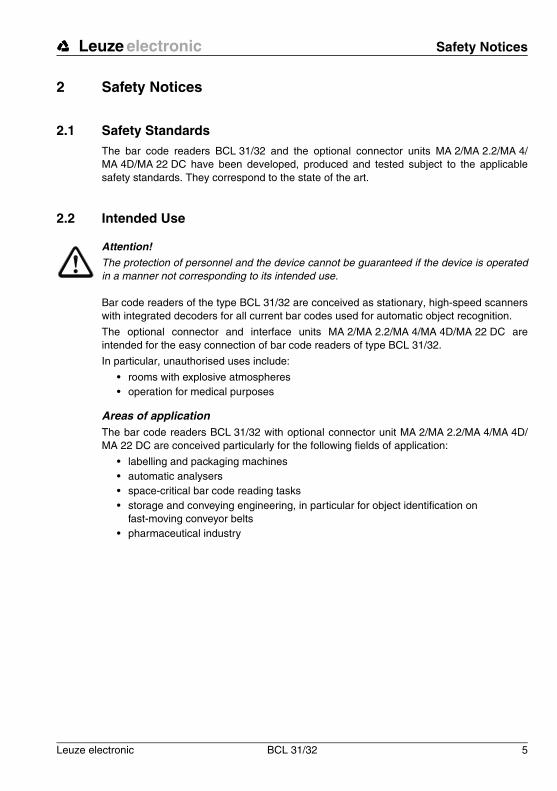
2.2 Intended Use
Attention!
The protection of personnel and the device cannot be guaranteed if the device is operatedin a manner not corresponding to its intended use.
Bar code readers of the type BCL 31/32 are conceived as stationary, high-speed scannerswith integrated decoders for all current bar codes used for automatic object recognition.
The optional connector and interface units MA 2/MA 2.2/MA 4/MA 4D/MA 22 DC areintended for the easy connection of bar code readers of type BCL 31/32.
In particular, unauthorised uses include:
• rooms with explosive atmospheres • operation for medical purposes
Areas of applicationThe bar code readers BCL 31/32 with optional connector unit MA 2/MA 2.2/MA 4/MA 4D/MA 22 DC are conceived particularly for the following fields of application:
• labelling and packaging machines• automatic analysers• space-critical bar code reading tasks• storage and conveying engineering, in particular for object identification on
fast-moving conveyor belts• pharmaceutical industry
Safety Notices Leuze electronic
6 BCL 31/32 Leuze electronic
2.3 Working Safely
Attention!
Access to or changes on the device, except where expressly described in this operatingmanual, is not authorised.
Safety regulations
Observe the locally applicable legal regulations and the rules of the employer's liability insur-ance association.
Qualified personnel
Mounting, commissioning and maintenance of the device must only be carried out by qual-ified personnel. Electrical work must be carried out by a certified electrician.
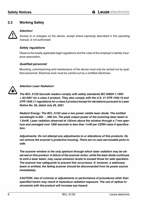
Attention Laser Radiation!
The BCL 31/32 barcode readers comply with safety standards IEC 60825-1:1993 + A2:2001 for a class 2 product. They also comply with the U.S. 21 CFR 1040.10 and CFR 1040.11 regulations for a class II product except for deviations pursuant to Laser Notice No. 50, dated July 26, 2001.
Radiant Energy: The BCL 31/32 uses a low power visible laser diode. The emitted wavelength is 650 … 690 nm. The peak output power of the scanning laser beam is 1.8mW. Laser radiation observed at 120mm above the window through a 7 mm aper-ture and averaged over 1000 seconds is less than 1mW per CDRH class II specifica-tion.
Adjustments: Do not attempt any adjustments to or alterations of this products. Do not remove the scanner’s protective housing. There are no user-serviceable parts in-side.
The scanner window is the only aperture through which laser radiation may be ob-served on this product. A failure of the scanner motor, while the laser diode continues to emit a laser beam, may cause emission levels to exceed those for safe operation. The scanner has safeguards to prevent this occurrence. If, however, a stationary beam is emitted, the failing scanner should be disconnected from its power source immediately.
CAUTION: Use of controls or adjustments or performance of procedures other than specified herein may result in hazardous radiation exposure. The use of optical in-struments with the product will increase eye hazard.
Leuze electronic Safety Notices
Leuze electronic BCL 31/32 7
TN
T 3
5/7-
24V
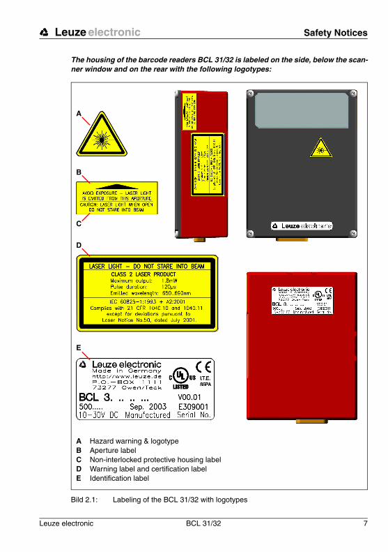
The housing of the barcode readers BCL 31/32 is labeled on the side, below the scan-ner window and on the rear with the following logotypes:
Bild 2.1: Labeling of the BCL 31/32 with logotypes
A
B
D
E
C
A Hazard warning & logotypeB Aperture labelC Non-interlocked protective housing labelD Warning label and certification labelE Identification label
Description Leuze electronic
8 BCL 31/32 Leuze electronic
3 Description
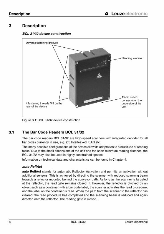
BCL 31/32 device construction
Figure 3.1: BCL 31/32 device construction
3.1 The Bar Code Readers BCL 31/32The bar code readers BCL 31/32 are high-speed scanners with integrated decoder for allbar codes currently in use, e.g. 2/5 Interleaved, EAN etc.
The many possible configurations of the device allow its adaptation to a multitude of readingtasks. Due to the small dimensions of the unit and the short minimum reading distance, theBCL 31/32 may also be used in highly constrained spaces.
Information on technical data and characteristics can be found in Chapter 4.
auto ReflActauto ReflAct stands for automatic Reflector Activation and permits an activation withoutadditional sensors. This is achieved by directing the scanner with reduced scanning beamtowards a reflector mounted behind the conveyor path. As long as the scanner is targetedat the reflector, the read gate remains closed. If, however, the reflector is blocked by anobject such as a container with a bar code label, the scanner activates the read procedure,and the label on the container is read. When the path from the scanner to the reflector hascleared, the read procedure has completed and the scanning beam is reduced and againdirected onto the reflector. The reading gate is closed.
Reading window
4 fastening threads M3 on the rear of the device
15-pin sub-D connector on the underside of the unit
Dovetail fastening grooves
Leuze electronic Description
Leuze electronic BCL 31/32 9
TN
T 3
5/7-
24V
3.2 Standalone operation
The bar code reader BCL 31/32 is operated as a "stand-alone" device. The BCL features a15-pin sub-D connector for the electrical connection of the supply voltage, the interface, andthe switching inputs.
With connection unitsThe connection units simplify the electrical installation of the bar code readers in standaloneoperation.
In addition, they permit the networking of several bar code readers; they can store operatingparameters (MA 4 / MA 4D), and can show parameters and operating data on a display(MA 4D).
A listing of the available connection units and associated short descriptions may be found inChapter 5. Separate data sheets are available that contain further details about the connec-tion units.
3.3 Networking
3.3.1 multiNet plus
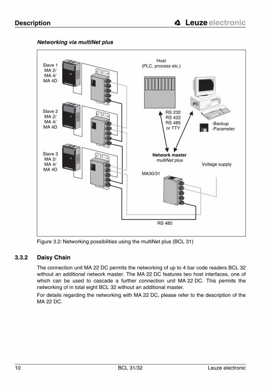
Up to 30 scanners can be networked together using the connector units MA 2, MA 4 orMA 4D and a bus master MA 30/31. To achieve this, each BCL 31 is assigned a separatehardware address in the respective connection unit. The devices are networked byconnecting the individual RS 485 interfaces in parallel.
In the Leuze multiNet plus, the individual network devices sequentially transfer their data tothe network master MA 30/31 when requested. In addition, each network device that isdeclared as slave receives a device address. It is set via a coding switch in the respectiveconnection unit. When exchanging a scanner, the device address remains stored in theMA 2. The connection units MA 4 and MA 4D also store the operating parameters of thescanner.
The master then transmits the data of all network devices via its host interface to a primaryPLC control system or a computer, i.e. it "collects" the scanner data in the network and trans-mits them to an interface on the host computer. This reduces interface costs (CPs) and timespent programming the software.
Two-wire RS 485The Leuze MultiNet plus is optimised for fast transmission of scanner data to a primary hostcomputer. The multiNet plus consists physically of a two-wire RS 485 interface throughwhich the multiNet plus software protocol is controlled. This makes wiring the network easyand inexpensive as slaves are connected to one another in parallel.
Interface modulesShielded, twisted pair conductors should be used for the multiNet. This allows a totalnetwork length of up to 1200 m. Connection of the network to the primary computer is madevia the host interface of the MA 30/31 which can be equipped with 4 different physical inter-face modules. Modules are available for RS 422, RS 232, TTY and RS 485.
Description Leuze electronic
10 BCL 31/32 Leuze electronic
Networking via multiNet plus
Figure 3.2: Networking possibilities using the multiNet plus (BCL 31)
3.3.2 Daisy Chain
The connection unit MA 22 DC permits the networking of up to 4 bar code readers BCL 32without an additional network master. The MA 22 DC features two host interfaces, one ofwhich can be used to cascade a further connection unit MA 22 DC. This permits thenetworking of in total eight BCL 32 without an additional master.
For details regarding the networking with MA 22 DC, please refer to the description of theMA 22 DC.
Slave 1 MA 2/MA 4/MA 4D
Slave 2 MA 2/MA 4/MA 4D
Slave 3 MA 2/MA 4/MA 4D
RS 232 RS 422 RS 485 or TTY
Host(PLC, process etc.)
-Backup-Parameter
Voltage supply
Network mastermultiNet plus
MA30/31
RS 485

Leuze electronic Technical Data
Leuze electronic BCL 31/32 11
TN
T 3
5/7-
24V
4 Technical Data
4.1 General Specifications BCL 31/32
Optical DataLight source Laser diode 650nmScanning rate BCL with M optics: 1000scans/s
BCL with F optics: 800scans/sBCL with L optics: 800scans/s
Resolution BCL 3x xM 100: m = 0.2mm … 0.5mmBCL 3x xF 100: m = 0.3mm … 0.8mmBCL 3x xL 100: m = 0.35mm … 0.8mm
Beam deflection by means of rotating polygon mirror wheelReading distance see reading curveReading field opening see reading curveLaser safety class 2 accord. to IEC 60825-1:1993 + A2:2001
II accord. to CDRHCode types 2/5 Interleaved, Code 39, Code 128, EAN 128, EAN/UPC,
EAN Addendum, Codabar, Pharma Code, Code 93Software features selectable output format, autoConfig, autoControl, autoRe-
flAct, reference code comparison, multiple read, real time decoding, adjustment mode, diagnosis, reading gate con-trol, control of switching inputs and switching outputs, etc.
Electrical dataInterface type BCL 31: RS 485
BCL 32: RS 232Service interface RS232 with fixed data format,
9600Bd, 8 data bits, no parity, 1 stop bitBaud rate 110 … 115400BdData formats data bits: 7, 8, 9
parity: None, Even, Oddstop bits: 1, 2
Protocols with/without frame protocolACK/NAK, 3964 (R) RK 512, RTS/CTSX ON / X OFF, multiNet plus
Ports BCL 31: 1 switching output, 1 switching inputBCL 32: 2 switching outputs, 2 switching inputs
LED green device ready (Power On)Operating voltage 1)
1) The unit is to be supplied by a Limited Power Supply complying with Cl. 2.5 of UL 60950(NEC Class 2) and rated from 10Vdc to 30Vdc, min. 320 mA. The unit shall be installed in accordance to the NEC, Article 725-52.
10 … 30VPower consumption 3.2 W
Additional FunctionsautoReflAct automatic reading activation via reflector

Technical Data Leuze electronic
12 BCL 31/32 Leuze electronic
Table 4.1: General specifications
4.2 Dimensioned and Connection Drawings
BCL 31/32
Figure 4.1: Dimensioned drawing BCL 31/32
Mechanical dataProtection class IP 65Weight 400 gDimensions (W x H x D) 120 x 90 x 43mmHousing diecast aluminium
Environmental dataAmbient temp. (operation/storage)
0°C … +40°C/-20°C … +60°C
Air humidity max. 90% rel. humidity, non-condensing Vibration IEC 60068-2-6, test FCShock IEC 60068-2-27, test EaElectromagnetic compatibility EN 61326-1,
IEC 61000-4-2, -3, -4 and -6,
Plan viewRear view
Leuze electronic Technical Data
Leuze electronic BCL 31/32 13
TN
T 3
5/7-
24V
4.3 Optical Data
Notice!
Please note that the size of the bar code module influences the maximum reading distanceand the width of the reading field.Therefore, when selecting a mounting location and/or thebar code label, take into account the different reading characteristics of the scanner with var-ious bar code modules.
For different reading tasks, the BCL 31/32 is available in various versions, both as a rasterscanner and as a single line scanner. Please refer to the following table or the respectivescanning curves for ratings.
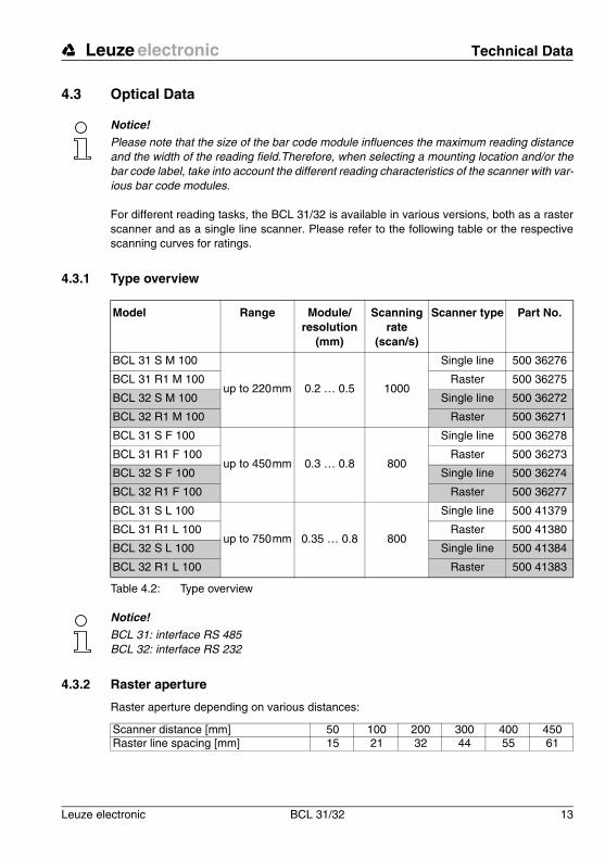
4.3.1 Type overview
Table 4.2: Type overview
Notice!
BCL 31: interface RS 485BCL 32: interface RS 232
4.3.2 Raster aperture
Raster aperture depending on various distances:
Model Range Module/resolution
(mm)
Scanning rate
(scan/s)
Scanner type Part No.
BCL 31 S M 100
up to 220mm 0.2 … 0.5 1000
Single line 500 36276
BCL 31 R1 M 100 Raster 500 36275
BCL 32 S M 100 Single line 500 36272
BCL 32 R1 M 100 Raster 500 36271
BCL 31 S F 100
up to 450mm 0.3 … 0.8 800
Single line 500 36278
BCL 31 R1 F 100 Raster 500 36273
BCL 32 S F 100 Single line 500 36274
BCL 32 R1 F 100 Raster 500 36277
BCL 31 S L 100
up to 750mm 0.35 … 0.8 800
Single line 500 41379
BCL 31 R1 L 100 Raster 500 41380
BCL 32 S L 100 Single line 500 41384
BCL 32 R1 L 100 Raster 500 41383
Scanner distance [mm] 50 100 200 300 400 450Raster line spacing [mm] 15 21 32 44 55 61

Technical Data Leuze electronic
14 BCL 31/32 Leuze electronic
4.3.3 Optics variants and reading fields
The BCL 31/32 is available with two different optics. The optics differ in range and resolution(see Chapter 4.3.1).
• Optic M: for small to medium modules• Optic F: for medium to large modules• Optic L: for medium to large modules
The following graphic displays the scanning curves of the various BCL models.
Notice!
Please notice that the real scanning curves are also influenced by factors such as labellingmaterial, printing quality, scanning angle, printing contrast etc., and may thus deviate fromthe scanning curves specified here.
Scanning curves BCL 31/32 with optic M
Figure 4.2: Reading field, optics model M (medium density, normal range)
-70
-60
-50
-40
-30
-20
-10
0
10
20
30
40
50
60
70
0 20 40 60 80 100 120 140 160 180 200 220
m=0,2
m=0,3
m=0,5
Reading distance [mm]
Rea
ding
fiel
d w
idth
[mm
]

Leuze electronic Technical Data
Leuze electronic BCL 31/32 15
TN
T 3
5/7-
24V
Scanning curves BCL 31/32 with optic F
Figure 4.3: Reading field, optics model F (low density, long range)
Scanning curves BCL 31/32 with optic L
Figure 4.4: Reading field, optics model L (low density, long range)
-100
-90
-80-70
-60
-50
-40
-30-20
-10
0
10
2030
40
50
60
7080
90
100
0 20 40 60 80 100 120 140 160 180 200 220 240 260 280 300 320 340 360 380 400 420 440 460m=0,3
m=0,5
m=0,8
Reading distance [mm]
Rea
ding
fiel
d w
idth
[mm
]
-200
-150
-100
-50
0
50
100
150
200
0 50 100 150 200 250 300 350 400 450 500 550 600 650 700 750 800
m=0,35
m=0,5
m=0,8
Reading distance [mm]
Rea
ding
fiel
d w
idth
[mm
]

Accessories / Order Designation Leuze electronic
16 BCL 31/32 Leuze electronic
5 Accessories / Order Designation
5.1 Accessories
Notice!
Products from Leuze electronic GmbH + Co KG can be ordered from any of the sales andservice offices listed on the back page of this operating manual.
Table 5.1: Accessories / Order Designation
5.1.1 Connection units
Notice!
The connection units are described here in brief only. For further information regarding theconnection units please refer to the relevant data sheets.
Symbol Order No. Short Description
MA 2 500 31256Coupling unit MA 2 for BCL 31;
standard, multiNet Slave with host interface RS 485
MA 2.2 500 31538Coupling unit MA 2.2 for BCL 32;
standard, multiNet Slave with host interface RS 232
MA 22 DC 500 31496 Daisy chain connection unit for four BCL 32
MA 4 500 31537 Connection unit for BCL 31/32 with parameter memory
MA 4D 500 31536Connection unit for BCL 31/32 with parameter memory
and display
BT 56 500 27375 Mounting bracket with dovetail for rod
KB 031-3000 500 35355Connection cable between BCL and MA,
length: 3m
KB 040-3000 500 26658Connection cable between BCL and MA in L version,
length: 3m
KB 040-6000 500 29381Connection cable between BCL and MA in L version,
length: 6m
KB 040-10000 500 29382Connection cable between BCL and MA in L version,
length: 10m
BCLConfig 500 60298 Programming software

Leuze electronic Accessories / Order Designation
Leuze electronic BCL 31/32 17
TN
T 3
5/7-
24V
Connector unit MA 2/MA 2.2
The connection units MA 2/MA 2.2 are used to simplify the electrical installation of the BCL31/32. They have the following advantages compared to the installation of the BCL 31/32 asa standalone device:
• Terminals for switching inputs and outputs, including supply voltage
• Terminals for feed-through of the RS 485 connection (MA 2)
• 9-pin sub D plug for service interface
• Operating mode switch: service operation/standard operation
• Rotary switch for address setting
Figure 5.1: Connector unit MA 2/MA 2.2
}0.0
5
}0.0
5
}0.05
0
80
45
104.5
0
40.8
49.2
9085.5 }0.05
(4x)3x45ß
180
167.
5
150.
5
12.5
29.5
Fastening holes Ø 5mm
Accessories / Order Designation Leuze electronic
18 BCL 31/32 Leuze electronic
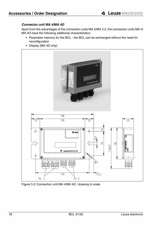
Connector unit MA 4/MA 4DApart from the advantages of the connection units MA 2/MA 2.2, the connection units MA 4/MA 4D have the following additional characteristics:
• Parameter memory for the BCL - the BCL can be exchanged without the need for reconfiguration
• Display (MA 4D only)
Figure 5.2: Connection unit MA 4/MA 4D / drawing to scale
Leuze electronic Accessories / Order Designation
Leuze electronic BCL 31/32 19
TN
T 3
5/7-
24V
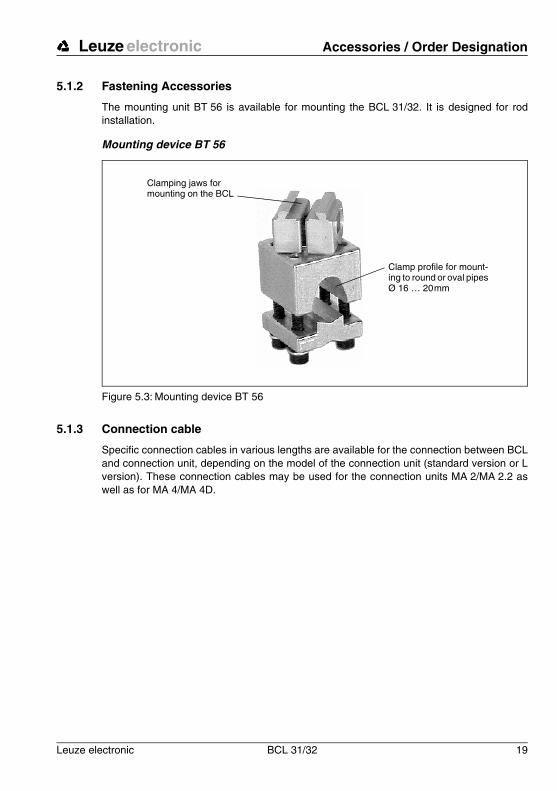
5.1.2 Fastening Accessories
The mounting unit BT 56 is available for mounting the BCL 31/32. It is designed for rodinstallation.
Mounting device BT 56
Figure 5.3: Mounting device BT 56
5.1.3 Connection cable
Specific connection cables in various lengths are available for the connection between BCLand connection unit, depending on the model of the connection unit (standard version or Lversion). These connection cables may be used for the connection units MA 2/MA 2.2 aswell as for MA 4/MA 4D.
Clamping jaws for mounting on the BCL
Clamp profile for mount-ing to round or oval pipes Ø 16 … 20mm

Installation Leuze electronic
20 BCL 31/32 Leuze electronic
6 Installation
6.1 Storage, Transportation
Attention!
When transporting, package the device so that it is protected against collision and humidity.Optimal protection is achieved when using the original packaging. Heed the required envi-ronmental conditions specified in the technical data.
Unpacking
! Check the packaging for any damage. If damage is found, notify the post office or ship-ping agent as well as the supplier.
! Check the delivery contents using your order and the delivery papers:
• delivered quantity
• device type and model as indicated on the nameplate
• accessories
• operating manual
The name plates provide information as to what BCL-type your device is. For specific infor-mation, please refer to Chapter 4.3.1.
Name plates, BCL-models
Figure 6.1: Device type plate BCL 31/32
! Save the original packaging for later storage or shipping.
If you have any questions concerning your shipment, please contact your supplier or yourlocal Leuze electronic sales office.
! Observe the local regulations regarding disposal and packaging.
Cleaning
! Clean the glass window of the BCL 31/32 with a soft cloth before mounting.Remove all packaging remains, e.g. carton fibres or Styrofoam balls.
Attention!
Do not use aggressive cleaning agents such as thinner or acetone for cleaning the device.
Leuze electronic Installation
Leuze electronic BCL 31/32 21
TN
T 3
5/7-
24V
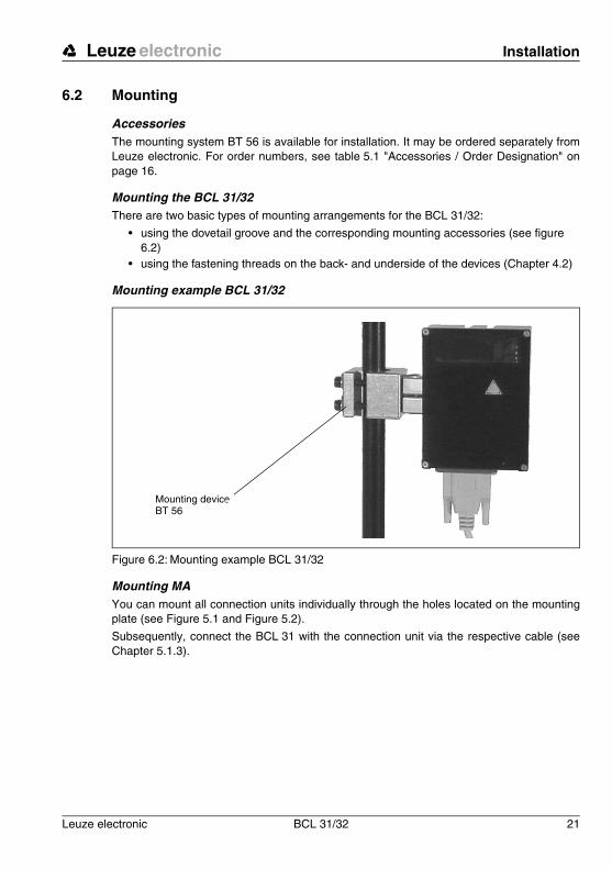
6.2 Mounting
AccessoriesThe mounting system BT 56 is available for installation. It may be ordered separately fromLeuze electronic. For order numbers, see table 5.1 "Accessories / Order Designation" onpage 16.
Mounting the BCL 31/32There are two basic types of mounting arrangements for the BCL 31/32:
• using the dovetail groove and the corresponding mounting accessories (see figure 6.2)
• using the fastening threads on the back- and underside of the devices (Chapter 4.2)
Mounting example BCL 31/32
Figure 6.2: Mounting example BCL 31/32
Mounting MAYou can mount all connection units individually through the holes located on the mountingplate (see Figure 5.1 and Figure 5.2).
Subsequently, connect the BCL 31 with the connection unit via the respective cable (seeChapter 5.1.3).
Mounting device BT 56
Installation Leuze electronic
22 BCL 31/32 Leuze electronic
6.2.1 Device Arrangement
Selecting a mounting location
In order to select the right mounting location, several factors must be considered:
• size, orientation, and position tolerance of the bar codes on the objects to be scanned
• the reading field of the BCL 31/32 in relation to the bar-code module width
• the resulting minimum and maximum reading distance from the respective reading field
For specific information, please refer to Chapter 4.3.
Notice!
The best reading results are obtained when
• the bar code is moved in a plane that is parallel to the reading window,
• the reading distance lies in the middle area of the reading field.
• you do not use high-gloss labels.
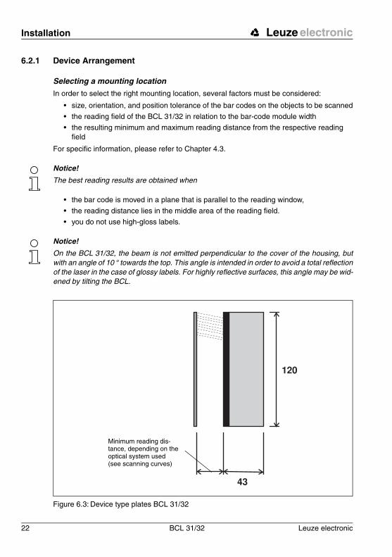
Notice!
On the BCL 31/32, the beam is not emitted perpendicular to the cover of the housing, butwith an angle of 10 ° towards the top. This angle is intended in order to avoid a total reflectionof the laser in the case of glossy labels. For highly reflective surfaces, this angle may be wid-ened by tilting the BCL.
Figure 6.3: Device type plates BCL 31/32
Minimum reading dis-tance, depending on the optical system used (see scanning curves)
Leuze electronic Installation
Leuze electronic BCL 31/32 23
TN
T 3
5/7-
24V
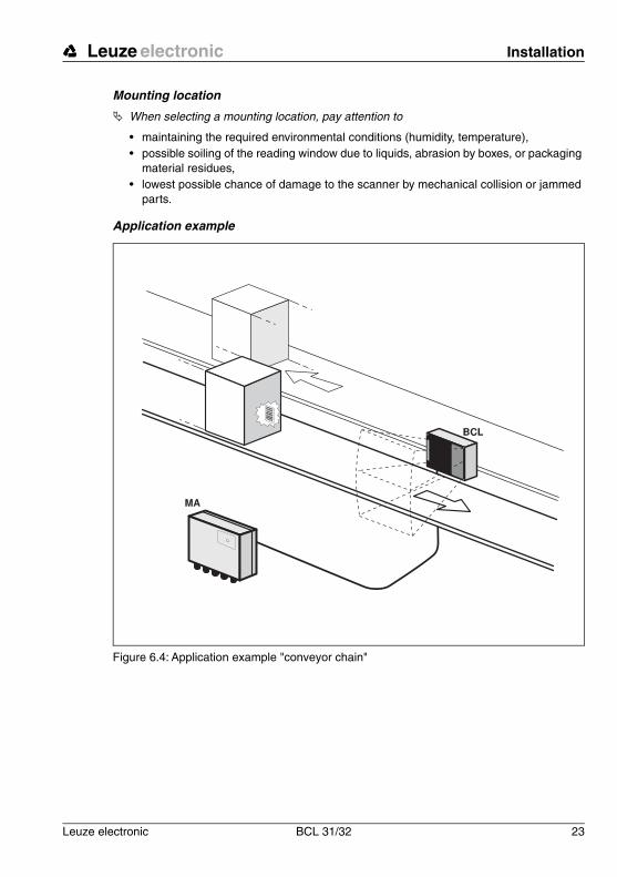
Mounting location
! When selecting a mounting location, pay attention to
• maintaining the required environmental conditions (humidity, temperature), • possible soiling of the reading window due to liquids, abrasion by boxes, or packaging
material residues,• lowest possible chance of damage to the scanner by mechanical collision or jammed
parts.
Application example
Figure 6.4: Application example "conveyor chain"
Installation Leuze electronic
24 BCL 31/32 Leuze electronic
6.3 Connection
Attention!
Never open the device yourself, as this may compromise protection class IP 65.
Before connecting the device, be sure that the supply voltage agrees with the value printedon the nameplate.
Connection of the device and maintenance work while under voltage must only be carriedout by a qualified electrician.
Power supply: The unit is to be supplied by a Limited Power Supply complying with Cl. 2.5of UL 60950 (NEC Class 2) and rated from 10 Vdc to 30 Vdc, min. 320 mA. The unit shallbe installed in accordance to the NEC, Article 725-52.
Be sure that the earthing conductor is connected correctly. Error-free operation is only guar-anteed when the device is properly earthed.
If faults cannot be corrected, the device should be removed from operation and protectedagainst possible use.
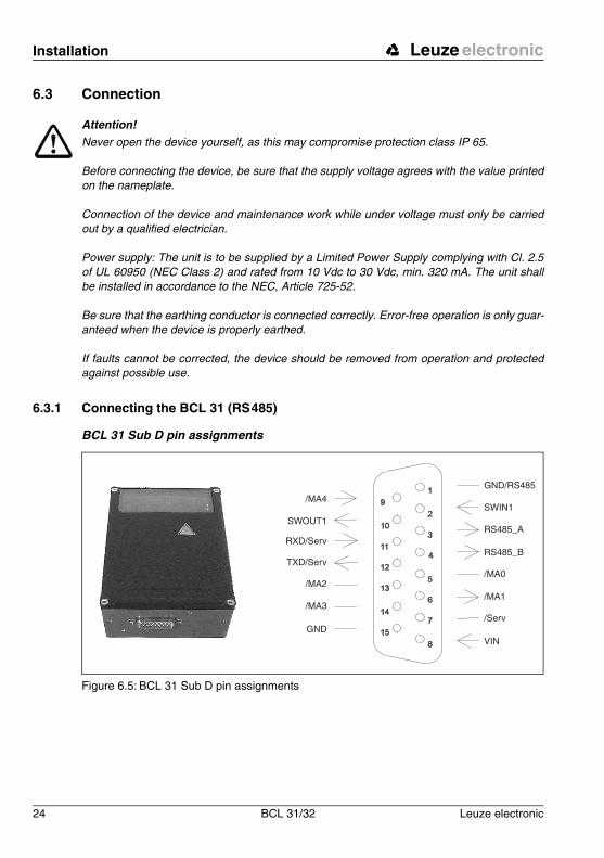
6.3.1 Connecting the BCL 31 (RS485)
BCL 31 Sub D pin assignments
Figure 6.5: BCL 31 Sub D pin assignments
GND/RS485
GND
/MA3
/MA2
TXD/Serv
RXD/Serv
SWOUT1
/MA4SWIN1
/MA1
/Serv
VIN
RS485_A
RS485_B
/MA0
Leuze electronic Installation
Leuze electronic BCL 31/32 25
TN
T 3
5/7-
24V
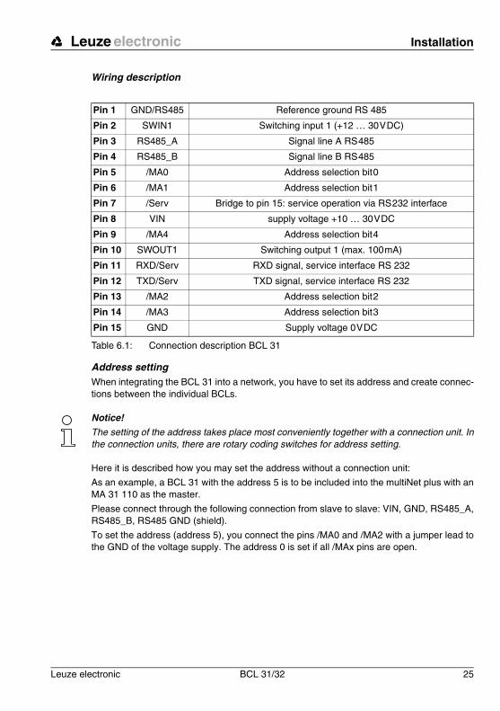
Wiring description
Table 6.1: Connection description BCL 31
Address settingWhen integrating the BCL 31 into a network, you have to set its address and create connec-tions between the individual BCLs.
Notice!
The setting of the address takes place most conveniently together with a connection unit. Inthe connection units, there are rotary coding switches for address setting.
Here it is described how you may set the address without a connection unit:
As an example, a BCL 31 with the address 5 is to be included into the multiNet plus with anMA 31 110 as the master.
Please connect through the following connection from slave to slave: VIN, GND, RS485_A,RS485_B, RS485 GND (shield).
To set the address (address 5), you connect the pins /MA0 and /MA2 with a jumper lead tothe GND of the voltage supply. The address 0 is set if all /MAx pins are open.
Pin 1 GND/RS485 Reference ground RS 485
Pin 2 SWIN1 Switching input 1 (+12 … 30VDC)
Pin 3 RS485_A Signal line A RS485
Pin 4 RS485_B Signal line B RS485
Pin 5 /MA0 Address selection bit0
Pin 6 /MA1 Address selection bit1
Pin 7 /Serv Bridge to pin 15: service operation via RS232 interface
Pin 8 VIN supply voltage +10 … 30VDC
Pin 9 /MA4 Address selection bit4
Pin 10 SWOUT1 Switching output 1 (max. 100mA)
Pin 11 RXD/Serv RXD signal, service interface RS 232
Pin 12 TXD/Serv TXD signal, service interface RS 232
Pin 13 /MA2 Address selection bit2
Pin 14 /MA3 Address selection bit3
Pin 15 GND Supply voltage 0VDC
Installation Leuze electronic
26 BCL 31/32 Leuze electronic
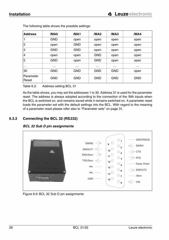
The following table shows the possible settings:
Table 6.2: Address setting BCL 31
As the table shows, you may set the addresses 1 to 30. Address 31 is used for the parameterreset. The address is always adopted according to the connection of the /MA inputs whenthe BCL is switched on, and remains saved while it remains switched on. A parameter resetloads the parameter set with the default settings into the BCL. With regard to the meaningof a parameter reset please refer also to "Parameter sets" on page 31.
6.3.2 Connecting the BCL 32 (RS232)
BCL 32 Sub D pin assignments
Figure 6.6: BCL 32 Sub D pin assignments
Address /MA0 /MA1 /MA2 /MA3 /MA4
1 GND open open open open
2 open GND open open open
3 GND GND open open open
4 open open GND open open
5 GND open GND open open
… … … … … …
30 GND GND GND GND open
Parameter Reset
GND GND GND GND GND
GND/RS232
GND
res.
res.
TXD/Serv
RXD/Serv
SWOUT1
SWIN2SWIN1
SWOUT2
/Serv
VIN
CTS
RTS
Daisy Chain

Leuze electronic Installation
Leuze electronic BCL 31/32 27
TN
T 3
5/7-
24V
Wiring description
Table 6.3: Wiring description BCL 32
Pin 1 Res. Reserved
Pin 2 SWIN1 Switching input 1 (+12 … 30VDC)
Pin 3 CTS CTS signal, host interface RS 232
Pin 4 RTS RTS signal, host interface RS232
Pin 5 Daisy Chain Bridge with pin 15: Daisy chain is active
Pin 6 SWOUT2 Switching output 2 (max. 100mA)
Pin 7 /Serv Bridge with pin 15: service operation
Pin 8 VIN supply voltage +10 … 30VDC
Pin 9 SWIN2 Switching input 2 (+12 … 30VDC)
Pin 10 SWOUT1 Switching output 1 (max. 100mA)
Pin 11 RXD/Serv RXD signal, service interface RS 232
Pin 12 TXD/Serv TXD signal, service interface RS 232
Pin 13 Res. Reserved
Pin 14 Res. Reserved
Pin 15 GND Supply voltage 0VDC
Installation Leuze electronic
28 BCL 31/32 Leuze electronic
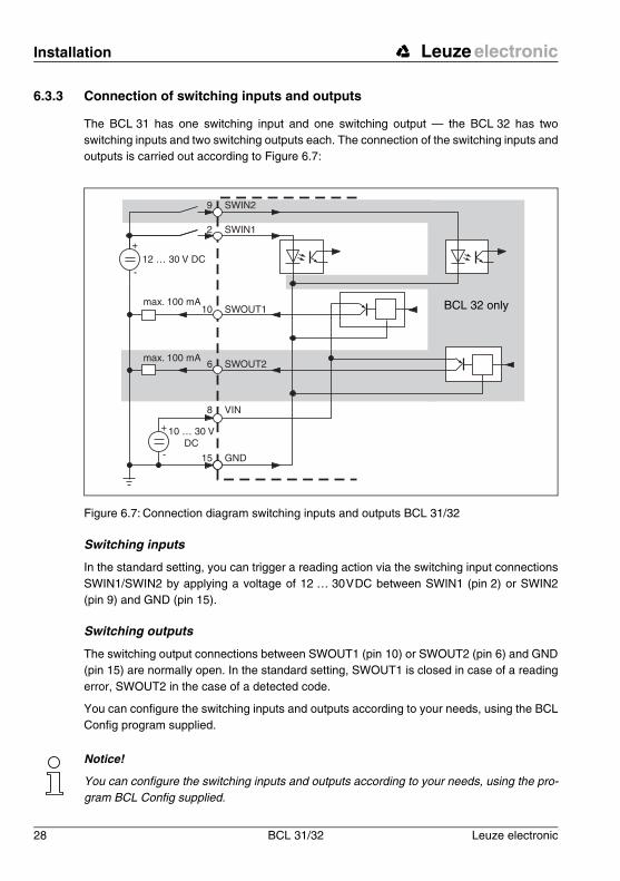
6.3.3 Connection of switching inputs and outputs
The BCL 31 has one switching input and one switching output — the BCL 32 has twoswitching inputs and two switching outputs each. The connection of the switching inputs andoutputs is carried out according to Figure 6.7:
Figure 6.7: Connection diagram switching inputs and outputs BCL 31/32
Switching inputs
In the standard setting, you can trigger a reading action via the switching input connectionsSWIN1/SWIN2 by applying a voltage of 12 … 30VDC between SWIN1 (pin 2) or SWIN2(pin 9) and GND (pin 15).
Switching outputs
The switching output connections between SWOUT1 (pin 10) or SWOUT2 (pin 6) and GND(pin 15) are normally open. In the standard setting, SWOUT1 is closed in case of a readingerror, SWOUT2 in the case of a detected code.
You can configure the switching inputs and outputs according to your needs, using the BCLConfig program supplied.
Notice!
You can configure the switching inputs and outputs according to your needs, using the pro-gram BCL Config supplied.
10 … 30 VDC
12 … 30 V DC
SWIN29
SWIN12
SWOUT110
SWOUT26
GND15
VIN8
max. 100 mA
max. 100 mA
BCL 32 only
Leuze electronic Installation
Leuze electronic BCL 31/32 29
TN
T 3
5/7-
24V
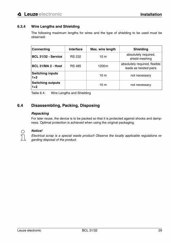
6.3.4 Wire Lengths and Shielding
The following maximum lengths for wires and the type of shielding to be used must beobserved:
Table 6.4: Wire Lengths and Shielding
6.4 Disassembling, Packing, Disposing
RepackingFor later reuse, the device is to be packed so that it is protected against shocks and damp-ness. Optimal protection is achieved when using the original packaging.
Notice!
Electrical scrap is a special waste product! Observe the locally applicable regulations re-garding disposal of the product.
Connecting Interface Max. wire length Shielding
BCL 31/32 - Service RS 232 10 mabsolutely required,
shield meshing
BCL 31/MA 2 - Host RS 485 1200mabsolutely required, flexible
leads as twisted pairs
Switching inputs 1+2
10 m not necessary
Switching outputs 1+2
10 m not necessary
Commissioning Leuze electronic
30 BCL 31/32 Leuze electronic
7 Commissioning
7.1 Measures to be performed prior to the first commissioning
! Before commissioning, familiarise yourself with the operation and configuration of the device(s)!
! Before switching on, recheck all connections and ensure that they have been properly made.
Setting the device addressThe device addresses are set via address bits. For setting instructions refer to Chapter 6.3.1.
If the BCL is connected to a connection unit, the device address can also be set convenientlyvia a rotary coding switch in the connection unit.
! Set the device address to
• 0, if the BCL 31/32 will not be operated in a network,• 1…30, if several BCL 31 are operated in a network. Each multiNet plus network
device must have a different device address assigned to it.• 31, if you want to carry out a parameter reset. The parameters set with the default set-
tings will then be loaded into the BCL when it is switched off and on.
Attention!
A parameter reset overwrites all customer-specific settings. Make sure that you only set theaddress 31 if you want to work with the default settings and if you have saved your customer-specific settings e.g., using the "BCLConfig" program.
Notice!
From the hardware address (device address > 0), the BCL 31 detects that networking is re-quired. With the BCL 31/32, it is possible to perform a reset using the software and the onlinecommands.In addition, it is possible to perform a reset by switching off the supply volt-age.The parameters are not lost as a result of the reset. For information on the reset com-mands, see Chapter 9. The LED remains dark during a reset; the green LED illuminateswhen the device is ready for operation.
7.2 Function Test
"Power On" testAfter connecting the operating voltage, the BCL 31/32 carry out an automatic "Power On"function test. Subsequently, the green LED lights up in the optics window of the BCL 31/32.
InterfaceProper function of the interface can be tested easiest in service operation using the serviceinterface with the "BCLConfig" programming software and a notebook computer. For ordernumbers, see table 5.1 on page 16.
Leuze electronic Commissioning
Leuze electronic BCL 31/32 31
TN
T 3
5/7-
24V
Online commands
Using the 'Online' commands, the important device functions can be checked, e.g. properfunctioning of the laser.
Problems
Should problems occur during device commissioning, refer first to Chapter 8.2. Should aproblem persist after checking all electrical connections and settings on the devices andhost, please contact a Leuze service office near you (see the back page of this operatingmanual).
7.3 Setting the Parameters
You have now commissioned the BCL. Usually, you will have to configure it before you canuse it. Using the parameter options made available by the BCL, you may configure the BCLto suit your individual area of application. For instructions regarding the various settingoptions refer to Chapter 9 or to the online help of the BCLConfig program.
In order to operate the BCL, it is typically sufficient to set code type and code length inaccordance with the bar codes that are to be read. However, depending on the application,you will additionally activate the autoReflAct function and configure the switching inputs andoutputs according to your requirements.
The setting of code type and code length is usually accomplished by using the programBCLConfig, see "Installing the "BCLConfig"-software" on page 35.
To understand what is happening during the parameter setting, the following Chapter 7.3.1briefly explains the various parameter sets.
The setting of the parameter sets then takes place in the operating mode "service", which isdescribed in Chapter 7.3.2.
7.3.1 Parameter sets
In the BCL 31/32, three different parameter sets are administered:
• parameter set with the default settings in the ROM
• current parameter set in the EEPROM
• working copy of the current parameter set in the RAM
Before a parameter set is loaded into the memory of the BCL 31/32 processor, the validityof the parameter set is verified using checksums.
Factory default parameter set
This parameter set contains the default settings made ex works for all BCL 31/32 parame-ters. It is permanently stored in the ROM of the BCL 31/32. The parameter set with thedefault settings is loaded into the memory of the BCL 31/32
• the first time the device is commissioned after delivery,
• following the command "Factory Default" in the parameterisation program,
• if the checksums of the current parameter set are invalid.
Commissioning Leuze electronic
32 BCL 31/32 Leuze electronic
Current parameter setIn this parameter set, the current settings for all device parameters are stored. When theBCL 31/32 is in operation, the parameter set is stored in the EEPROM of the BCL 31/32.The current set can be stored:
• by copying a valid parameter set from the host computer• by means of an off-line setup with the PC setup program BCLConfig
The current parameter set is loaded into the memory of the BCL 31/32
• each time the supply voltage is connected• following a software reset
The current parameter set is overwritten by the parameter set with the default settings:
• by a parameter reset, see page 30
7.3.2 Service Operating Mode
Setting the required parameters is carried out easiest in the "service" operating mode. Theoperating mode "service" makes the following defined operating parameters available on aseparately wired RS232 interface, independent from the BCL's configuration for standardoperation:
• transfer rate 9600 baud• no parity• 8 data bits• 1 stop bit• prefix: STX• postfix: CR, LF
Service interface activeThe service interface is activated via a bridge between the pins 7 and 15 on the 15-pin sub-D connector. If the BCL 31/32 is operated with a connection unit, the service interface is acti-vated through a switch in the connection unit.
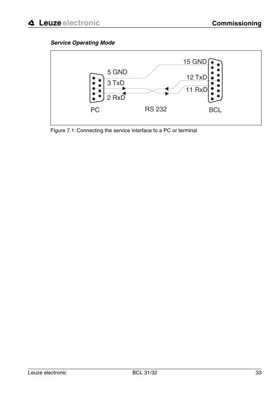
ConnectionYou can connect a PC or terminal to the BCL 31/32 via the serial interface and configure theBCL 31/32 through this connection. For this, you need a crossed RS 232 connection cable(null modem cable) that provides the connections RxD, TxD and GND. A hardware hand-shake via RTC, CTS is not supported at the service interface.
If the BCL is connected to a connection unit, you can use the 9-pin sub-D service connectorin the connection unit. For the respective connection specifications please refer to the datasheet of the connection unit.
Leuze electronic Commissioning
Leuze electronic BCL 31/32 33
TN
T 3
5/7-
24V
Service Operating Mode
Figure 7.1: Connecting the service interface to a PC or terminal
15 GND
12 TxD
11 RxD
BCLPC
Operation Leuze electronic
34 BCL 31/32 Leuze electronic
8 Operation
8.1 Display ElementsOn the BCL 31/32 there is an LED. It signals that the BCL is ready for operation.
8.2 Error HandlingError, warning and status messages of the BCL 31/32 are transmitted via the host interfaceonly.
Types of errorsErrors are divided up into the following types:
• Warnings• Serious errors
WarningsWarnings indicate temporary operating faults which do not effect the proper functioning ofthe device.
Serious errorsSerious errors impair the proper functioning of the device. The device must be re-initialised.
TroubleshootingIsolated warnings can be ignored, since the BCL 31/32 will continue to function properly.
Following a serious error, you should re-initialise the BCL. It will then usually again functionproperly. If a hardware problem is present, the BCL 31/32 will not re-initialise.
Warnings and errors which occur frequently can be corrected easiest using the BCLConfigsoftware.
If you cannot correct faults and errors with the software, please contact a Leuze electronicsales office or service facility. For addresses, please refer to the back page of this operatingmanual.
Leuze electronic Communicating with the Device
Leuze electronic BCL 31/32 35
TN
T 3
5/7-
24V
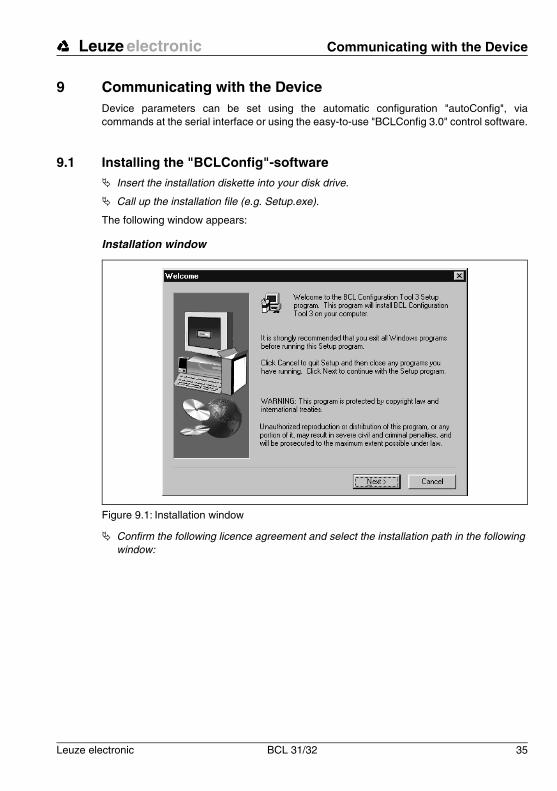
9 Communicating with the DeviceDevice parameters can be set using the automatic configuration "autoConfig", viacommands at the serial interface or using the easy-to-use "BCLConfig 3.0" control software.
9.1 Installing the "BCLConfig"-software! Insert the installation diskette into your disk drive.
! Call up the installation file (e.g. Setup.exe).
The following window appears:
Installation window
Figure 9.1: Installation window
! Confirm the following licence agreement and select the installation path in the following window:

Communicating with the Device Leuze electronic
36 BCL 31/32 Leuze electronic
Installation directory
Figure 9.2: Installation directory
! Confirm your entry with Continue, then follow the installation routine.
For further information, please see the online help for the "BCLConfig" software.
! After the successful installation, double-click on the file "BCLconfig.exe" to activate the configuration program.

Leuze electronic Important Parameters
Leuze electronic BCL 31/32 37
TN
T 3
5/7-
24V
10 Important Parameters
10.1 Code menu
Figure 10.1: Default setting of the code menu
Notice!
If the code EAN128 is to be read, 3 additional characters are to be set for the code identifier.
Code table Here, the codes which are to be decoded are set. We recommend enabling only the code types which are to actually be read with the corresponding element numbers.IMPORTANT: Code 1 has to be selected always. For more than one code type select the codes in consecutive order Code 1, Code 2, … .
Element number
In the field Element number, up to 3 element entries may be entered. An area is represented by a dashed line: e.g. 4-40 digits.With 2 or 3 different element entries by a comma: e.g: 8,13 digitsThe combination is also possible, but the range must be specified first: e.g.: 4-10,20 digits
Properties Behind the "Properties" button, to the right of the respective code, the code-specific settings, such as the check digit, can be selected.
Number of bar codes
Here, the number of the bar codes to be decoded within a read cycle (one reading gate) is set.
Important Parameters Leuze electronic
38 BCL 31/32 Leuze electronic
10.1.1 Properties of the Code menu
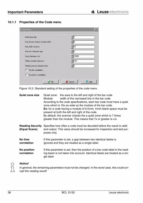
Figure 10.2: Standard setting of the properties of the code menu
Notice!
In general, the remaining parameters must not be changed. In the worst case, this could cor-rupt the reading result!
Quiet zone size Quiet zone: the area to the left and right of the bar codeModule: width of the narrowest line in the bar codeAccording to the code specifications, each bar code must have a quiet zone which is 10x as wide as the module of the bar code.Ex: for a code having a module of 0.5mm, 5mm blank space must be present at both the left and right of the code.By default, the scanner checks the a quiet zone which is 7 times greater than the module. This means that 7x or greater is o.k.
Reading Security (Equal Scans)
Specifies how often a code must be decoded before the result is valid and output. This value should be increased for inspection and test pur-poses only.
No time correlation
If this parameter is set, a gap between two identical labels is ignored and they are treated as a single label.
No position correlation
If this parameter is set, then the position of a bar code label in the read-ing beam is not taken into account. Identical labels are treated as a sin-gle label
Leuze electronic Important Parameters
Leuze electronic BCL 31/32 39
TN
T 3
5/7-
24V
10.2 Output menu
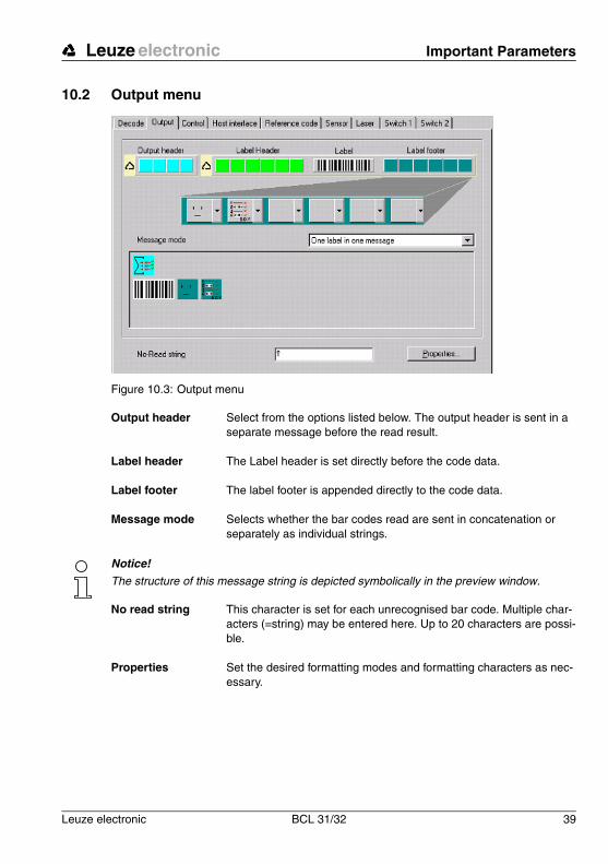
Figure 10.3: Output menu
Notice!
The structure of this message string is depicted symbolically in the preview window.
Output header Select from the options listed below. The output header is sent in a separate message before the read result.
Label header The Label header is set directly before the code data.
Label footer The label footer is appended directly to the code data.
Message mode Selects whether the bar codes read are sent in concatenation or separately as individual strings.
No read string This character is set for each unrecognised bar code. Multiple char-acters (=string) may be entered here. Up to 20 characters are possi-ble.
Properties Set the desired formatting modes and formatting characters as nec-essary.
Important Parameters Leuze electronic
40 BCL 31/32 Leuze electronic
10.3 Control
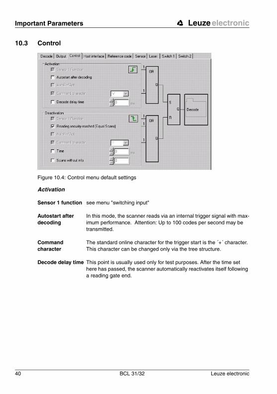
Figure 10.4: Control menu default settings
Activation
Sensor 1 function see menu "switching input"
Autostart after decoding
In this mode, the scanner reads via an internal trigger signal with max-imum performance. Attention: Up to 100 codes per second may be transmitted.
Command character
The standard online character for the trigger start is the ´+´ character. This character can be changed only via the tree structure.
Decode delay time This point is usually used only for test purposes. After the time set here has passed, the scanner automatically reactivates itself following a reading gate end.

Leuze electronic Important Parameters
Leuze electronic BCL 31/32 41
TN
T 3
5/7-
24V
Deactivation
10.4 Communication
Figure 10.5: Standard setting of the communication menu
Select the desired baud rate, the stop bits, the data bits and the parity. In addition, varioushandshake modes and protocols can be set here.
Sensor 1 function see menu "switching input"
Reading security reached (equal scans)
If this item is activated, the read result is output immediately after the bar code is decoded. If the item is deactivated, the read result is sent only after the trigger signal is returned (=end of reading gate).
Command character
The standard online character for the trigger end is the ´-´ character.This character can be changed only via the tree structure.
Time For test purposes.If the scanner is activated, the reading gate is automatically closed by the scanner after this preset time has elapsed.
Scans without info Following a successful read, the scanner waits for this number of scans (sequential scans with no read result) before it automatically deactivates itself.
Important Parameters Leuze electronic
42 BCL 31/32 Leuze electronic
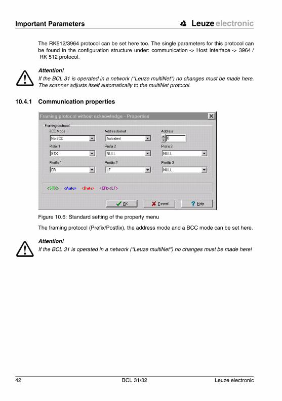
The RK512/3964 protocol can be set here too. The single parameters for this protocol canbe found in the configuration structure under: communication -> Host interface -> 3964 /RK 512 protocol.
Attention!
If the BCL 31 is operated in a network ("Leuze multiNet") no changes must be made here.The scanner adjusts itself automatically to the multiNet protocol.
10.4.1 Communication properties
Figure 10.6: Standard setting of the property menu
The framing protocol (Prefix/Postfix), the address mode and a BCC mode can be set here.
Attention!
If the BCL 31 is operated in a network ("Leuze multiNet") no changes must be made here!

Leuze electronic Important Parameters
Leuze electronic BCL 31/32 43
TN
T 3
5/7-
24V
10.5 Reference code
Figure 10.7: Reference code menu
A reference code is bar code information which is stored in the memory of the scanner.
This reference code can be compared with the current decoded bar code in various modesand, thus, set appropriately for the switching output. To do this, the switching output muststill be set to "By comparison of reference code X" in the "Switch" menu.
One way to store the reference code is to enter it manually in this menu. You can find furtheroptions of the reference code teach-in in the chapter on online commands.
Type Select the code type.
Info Contents of the reference code
Compare mode Select here how the internally stored reference code is to be com-pared with the decoded result.-> For additional comparison possibilities, please select the "Proper-ties" menu
Important Parameters Leuze electronic
44 BCL 31/32 Leuze electronic
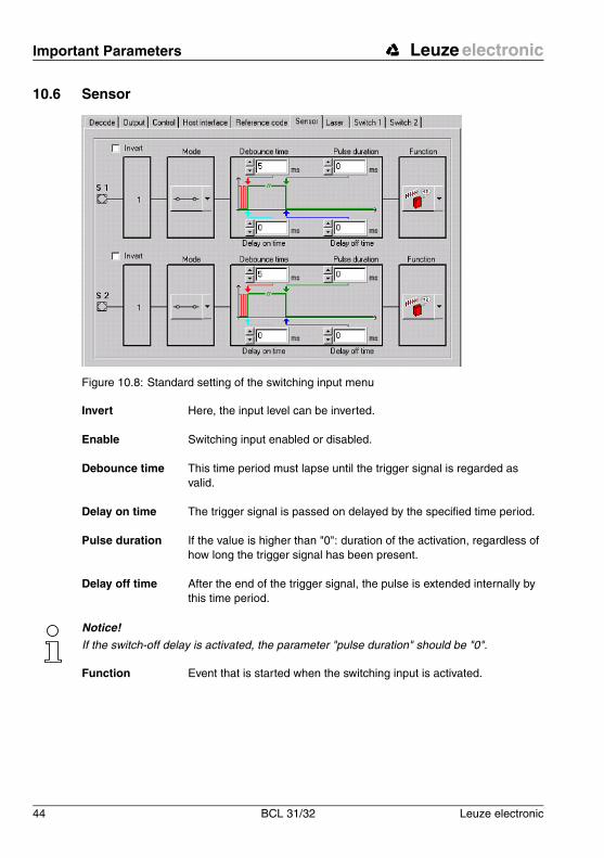
10.6 Sensor
Figure 10.8: Standard setting of the switching input menu
Notice!
If the switch-off delay is activated, the parameter "pulse duration" should be "0".
Invert Here, the input level can be inverted.
Enable Switching input enabled or disabled.
Debounce time This time period must lapse until the trigger signal is regarded as valid.
Delay on time The trigger signal is passed on delayed by the specified time period.
Pulse duration If the value is higher than "0": duration of the activation, regardless of how long the trigger signal has been present.
Delay off time After the end of the trigger signal, the pulse is extended internally by this time period.
Function Event that is started when the switching input is activated.
Leuze electronic Important Parameters
Leuze electronic BCL 31/32 45
TN
T 3
5/7-
24V
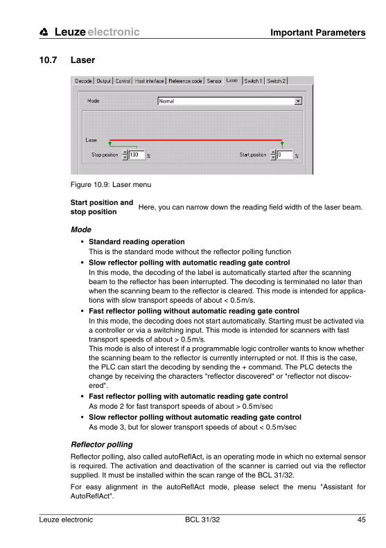
10.7 Laser
Figure 10.9: Laser menu
Mode
• Standard reading operation This is the standard mode without the reflector polling function
• Slow reflector polling with automatic reading gate controlIn this mode, the decoding of the label is automatically started after the scanning beam to the reflector has been interrupted. The decoding is terminated no later than when the scanning beam to the reflector is cleared. This mode is intended for applica-tions with slow transport speeds of about < 0.5m/s.
• Fast reflector polling without automatic reading gate controlIn this mode, the decoding does not start automatically. Starting must be activated via a controller or via a switching input. This mode is intended for scanners with fast transport speeds of about > 0.5m/s.This mode is also of interest if a programmable logic controller wants to know whether the scanning beam to the reflector is currently interrupted or not. If this is the case, the PLC can start the decoding by sending the + command. The PLC detects the change by receiving the characters "reflector discovered" or "reflector not discov-ered".
• Fast reflector polling with automatic reading gate controlAs mode 2 for fast transport speeds of about > 0.5m/sec
• Slow reflector polling without automatic reading gate controlAs mode 3, but for slower transport speeds of about < 0.5m/sec
Reflector polling
Reflector polling, also called autoReflAct, is an operating mode in which no external sensoris required. The activation and deactivation of the scanner is carried out via the reflectorsupplied. It must be installed within the scan range of the BCL 31/32.
For easy alignment in the autoReflAct mode, please select the menu "Assistant forAutoReflAct".
Start position and stop position
Here, you can narrow down the reading field width of the laser beam.
Important Parameters Leuze electronic
46 BCL 31/32 Leuze electronic
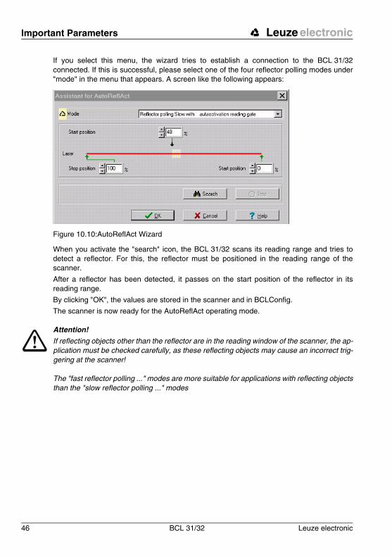
If you select this menu, the wizard tries to establish a connection to the BCL 31/32connected. If this is successful, please select one of the four reflector polling modes under"mode" in the menu that appears. A screen like the following appears:
Figure 10.10:AutoReflAct Wizard
When you activate the "search" icon, the BCL 31/32 scans its reading range and tries todetect a reflector. For this, the reflector must be positioned in the reading range of thescanner.
After a reflector has been detected, it passes on the start position of the reflector in itsreading range.
By clicking "OK", the values are stored in the scanner and in BCLConfig.
The scanner is now ready for the AutoReflAct operating mode.
Attention!
If reflecting objects other than the reflector are in the reading window of the scanner, the ap-plication must be checked carefully, as these reflecting objects may cause an incorrect trig-gering at the scanner!
The "fast reflector polling ..." modes are more suitable for applications with reflecting objectsthan the "slow reflector polling ..." modes
Leuze electronic Important Parameters
Leuze electronic BCL 31/32 47
TN
T 3
5/7-
24V
10.8 Switching output
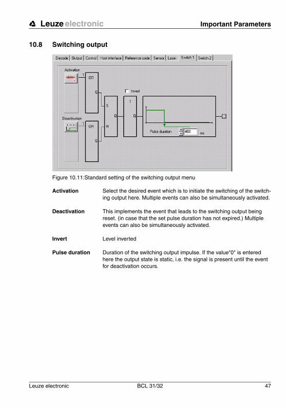
Figure 10.11:Standard setting of the switching output menu
Activation Select the desired event which is to initiate the switching of the switch-ing output here. Multiple events can also be simultaneously activated.
Deactivation This implements the event that leads to the switching output being reset. (in case that the set pulse duration has not expired.) Multiple events can also be simultaneously activated.
Invert Level inverted
Pulse duration Duration of the switching output impulse. If the value"0" is entered here the output state is static, i.e. the signal is present until the event for deactivation occurs.
Online commands Leuze electronic
48 BCL 31/32 Leuze electronic
11 Online commands
11.1 Overview of Commands and ParametersOnline commands can be used to send commands directly to the device for control andconfiguration.
For this, the BCL 31/ 32 has to be connected to a host or service computer via the serialinterface The commands can be sent either via the host or the service interface.
For information on the transmission protocol, please see Chapter 7.3.2.
With the commands, you can
Online commands
• Control/decode reading gate.
• Read/write/copy parameters.
• Carry out an automatic configuration.
• Teach/set reference code.
• Call up error messages.
• Call up statistical device information.
• Carry out a software reset in order to re-initialise the device.
Syntax
"Online" commands consist of one or two ASCII characters followed by command parame-ters.
No separation characters may be entered between the command and the command param-eter(s). Both small and capitalised letters may be used.
Example:
Command ’CA’: autoConfig function
Parameter ’+’: Activation
Transmitted is: ’CA+’
Notation
Commands, command parameters and returned data are enclosed between single quota-tion marks ’ ’.
Most "online" commands are acknowledged by the BCL 31/32 and any requested datareturned. For commands that are not acknowledged, command execution can be observedor monitored directly on the device.
Leuze electronic Online commands
Leuze electronic BCL 31/32 49
TN
T 3
5/7-
24V
11.1.1 General 'Online' Commands
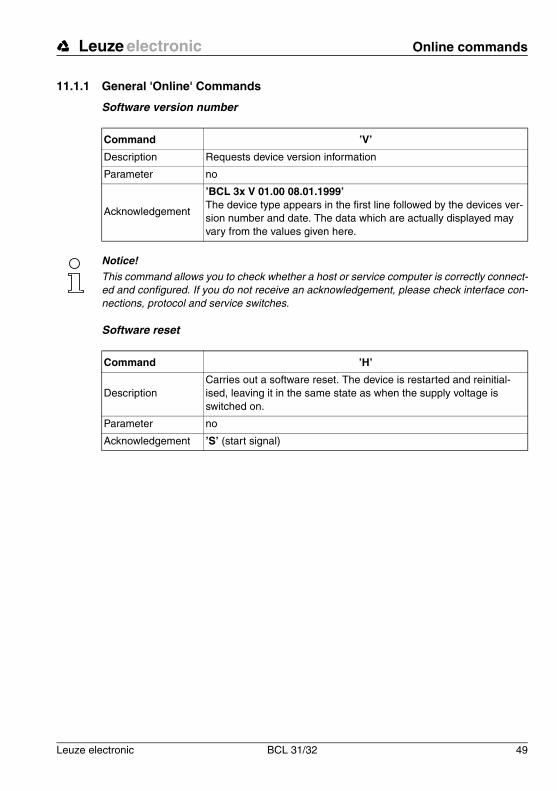
Software version number
Notice!
This command allows you to check whether a host or service computer is correctly connect-ed and configured. If you do not receive an acknowledgement, please check interface con-nections, protocol and service switches.
Software reset
Command ’V’
Description Requests device version information
Parameter no
Acknowledgement
’BCL 3x V 01.00 08.01.1999’The device type appears in the first line followed by the devices ver-sion number and date. The data which are actually displayed may vary from the values given here.
Command ’H’
DescriptionCarries out a software reset. The device is restarted and reinitial-ised, leaving it in the same state as when the supply voltage is switched on.
Parameter no
Acknowledgement ’S’ (start signal)

Online commands Leuze electronic
50 BCL 31/32 Leuze electronic
autoConfig
Command ’CA’
DescriptionActivates or deactivates the 'autoConfig' function. Certain label read-ing parameters are programmed automatically in the setup by the labels which are read while the 'autoConfig' function is active.
Parameter
’+’ activates ’autoConfig’/ rejects the last code read- deactivates ’autoConfig’ and stores the decoded data in the
current parameter set.
Acknowledgement
’CSx’x: Status
’0’ valid ’CA’ command’1’ invalid command’2’ autoConfig could not be activated’3’ autoConfig could not be deactivated’4’ Result could not be deleted
Description
’xx yy zzzzzz’xx: Code type of the read code
’01’ 2/5 Interleaved’02’ Code 39’06’ UPC (A, E)’07’ EAN’08’ Code 128, EAN 128’10’ EAN/UPC’11’ Codabar
yy Number of digits of the code detectedzzzzzz Contents of the decoded label. The ↑ appears if the label
was not correctly read.
Leuze electronic Online commands
Leuze electronic BCL 31/32 51
TN
T 3
5/7-
24V
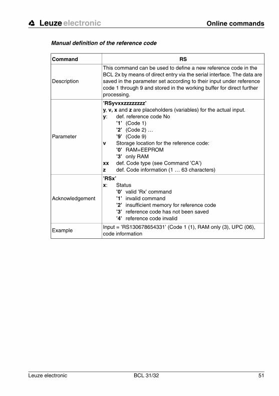
Manual definition of the reference code
Command RS
Description
This command can be used to define a new reference code in the BCL 2x by means of direct entry via the serial interface. The data are saved in the parameter set according to their input under reference code 1 through 9 and stored in the working buffer for direct further processing.
Parameter
’RSyvxxzzzzzzzz’y, v, x and z are placeholders (variables) for the actual input. y: def. reference code No
’1’ (Code 1) ’2’ (Code 2) … ’9’ (Code 9)
v Storage location for the reference code: ’0’ RAM+EEPROM’3’ only RAM
xx def. Code type (see Command ’CA’)z def. Code information (1 … 63 characters)
Acknowledgement
’RSx’x: Status
’0’ valid ’Rx’ command’1’ invalid command’2’ insufficient memory for reference code’3’ reference code has not been saved’4’ reference code invalid
ExampleInput = ’RS130678654331’ (Code 1 (1), RAM only (3), UPC (06), code information
Online commands Leuze electronic
52 BCL 31/32 Leuze electronic
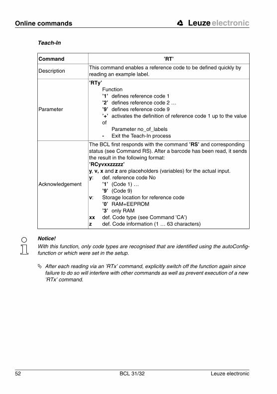
Teach-In
Notice!
With this function, only code types are recognised that are identified using the autoConfig-function or which were set in the setup.
! After each reading via an ’RTx’ command, explicitly switch off the function again since failure to do so will interfere with other commands as well as prevent execution of a new ’RTx’ command.
Command ’RT’
DescriptionThis command enables a reference code to be defined quickly by reading an example label.
Parameter
’RTy’Function’1’ defines reference code 1’2’ defines reference code 2 …’9’ defines reference code 9’+’ activates the definition of reference code 1 up to the value of
Parameter no_of_labels- Exit the Teach-In process
Acknowledgement
The BCL first responds with the command ’RS’ and corresponding status (see Command RS). After a barcode has been read, it sends the result in the following format:’RCyvxxzzzzz’y, v, x and z are placeholders (variables) for the actual input. y: def. reference code No
’1’ (Code 1) … ’9’ (Code 9)
v: Storage location for reference code’0’ RAM+EEPROM’3’ only RAM
xx def. Code type (see Command ’CA’)z def. Code information (1 … 63 characters)
Leuze electronic Online commands
Leuze electronic BCL 31/32 53
TN
T 3
5/7-
24V
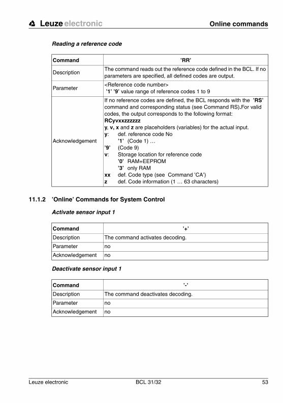
Reading a reference code
11.1.2 ’Online’ Commands for System Control
Activate sensor input 1
Deactivate sensor input 1
Command ’RR’
DescriptionThe command reads out the reference code defined in the BCL. If no parameters are specified, all defined codes are output.
Parameter<Reference code number> ’1’ ’9’ value range of reference codes 1 to 9
Acknowledgement
If no reference codes are defined, the BCL responds with the ’RS’ command and corresponding status (see Command RS).For valid codes, the output corresponds to the following format:RCyvxxzzzzzzy, v, x and z are placeholders (variables) for the actual input. y: def. reference code No
’1’ (Code 1) … ’9’ (Code 9)v: Storage location for reference code
’0’ RAM+EEPROM’3’ only RAM
xx def. Code type (see Command ’CA’)z def. Code information (1 … 63 characters)
Command ’+’
Description The command activates decoding.
Parameter no
Acknowledgement no
Command ’-’
Description The command deactivates decoding.
Parameter no
Acknowledgement no
Online commands Leuze electronic
54 BCL 31/32 Leuze electronic
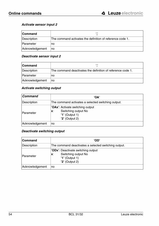
Activate sensor input 2
Deactivate sensor input 2
Activate switching output
Deactivate switching output
Command ’,’
Description The command activates the definition of reference code 1.
Parameter no
Acknowledgement no
Command ’.’
Description The command deactivates the definition of reference code 1.
Parameter no
Acknowledgement no
Command ’OA’
Description The command activates a selected switching output.
Parameter
’OAx’: Activate switching outputx: Switching output No
’1’ (Output 1)’2’ (Output 2)
Acknowledgement no
Command ’OD’
Description The command deactivates a selected switching output.
Parameter
’ODx’: Deactivate switching outputx: Switching output No
’1’ (Output 1)’2’ (Output 2)
Acknowledgement no
Leuze electronic Online commands
Leuze electronic BCL 31/32 55
TN
T 3
5/7-
24V
11.1.3 ’Online’ command for querying error messages
Query memory error messages
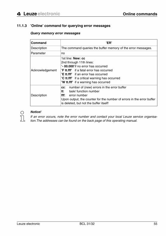
Notice!
If an error occurs, note the error number and contact your local Leuze service organisa-tion.The addresses can be found on the back page of this operating manual.
Command ’ER’
Description The command queries the buffer memory of the error messages.
Parameter no
Acknowledgement
1st line: New: cc2nd through 11th lines:’- 00.000’if no error has occurred’F tt.fff’ if a fatal error has occurred’E tt.fff’ if an error has occurred’C tt.fff’ if a critical warning has occurred’W tt.fff’ if a warning has occurred
Description
cc: number of (new) errors in the error buffertt: task/ function numberfff: error numberUpon output, the counter for the number of errors in the error buffer is deleted, but not the buffer itself!
Online commands Leuze electronic
56 BCL 31/32 Leuze electronic
11.1.4 ’Online’ Commands for Parameter Set Operations
Definitions
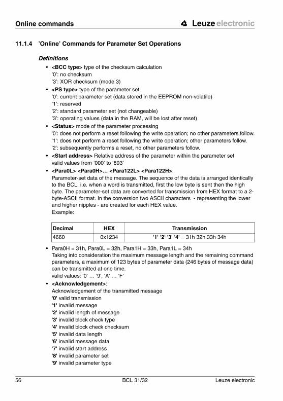
• <BCC type> type of the checksum calculation’0’: no checksum’3’: XOR checksum (mode 3)
• <PS type> type of the parameter set’0’: current parameter set (data stored in the EEPROM non-volatile)’1’: reserved ’2’: standard parameter set (not changeable)’3’: operating values (data in the RAM, will be lost after reset)
• <Status> mode of the parameter processing'0': does not perform a reset following the write operation; no other parameters follow.'1': does not perform a reset following the write operation; other parameters follow.'2': subsequently performs a reset, no other parameters follow.
• <Start address> Relative address of the parameter within the parameter setvalid values from ’000’ to ’893’
• <Para0L> <Para0H>… <Para122L> <Para122H>:Parameter-set data of the message. The sequence of the data is arranged identically to the BCL, i.e. when a word is transmitted, first the low byte is sent then the high byte. The parameter-set data are converted for transmission from HEX format to a 2-byte-ASCII format. In the conversion two ASCII characters - representing the lower and higher nipples - are created for each HEX value.Example:
• Para0H = 31h, Para0L = 32h, Para1H = 33h, Para1L = 34hTaking into consideration the maximum message length and the remaining command parameters, a maximum of 123 bytes of parameter data (246 bytes of message data) can be transmitted at one time.valid values: '0' … '9', 'A' … 'F'
• <Acknowledgement>:Acknowledgement of the transmitted message'0' valid transmission'1' invalid message '2' invalid length of message '3' invalid block check type'4' invalid block check checksum'5' invalid data length '6' invalid message data '7' invalid start address'8' invalid parameter set '9' invalid parameter type
Decimal HEX Transmission
4660 0x1234 '1' '2' '3' '4' = 31h 32h 33h 34h
Leuze electronic Online commands
Leuze electronic BCL 31/32 57
TN
T 3
5/7-
24V
Copy parameter set
Request parameter set from the BCL
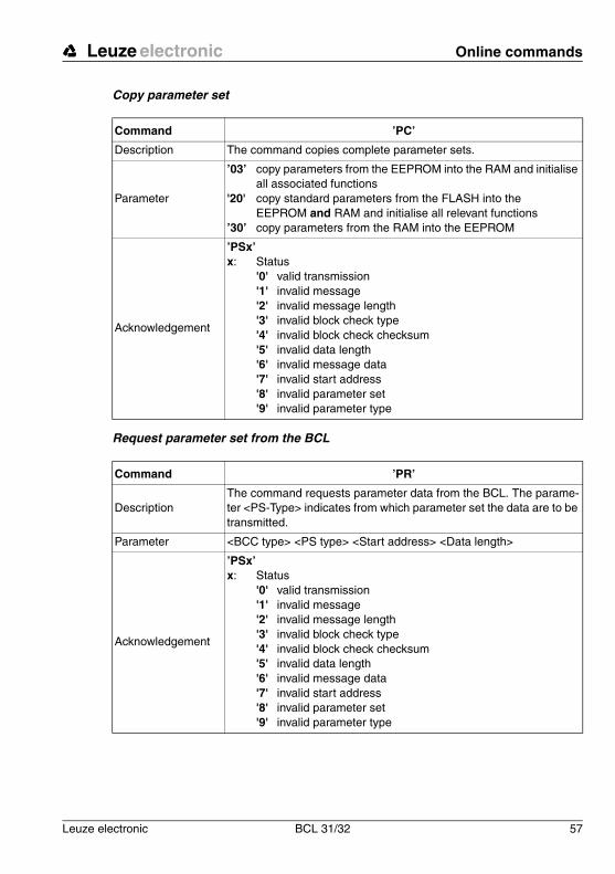
Command ’PC’
Description The command copies complete parameter sets.
Parameter
’03’ copy parameters from the EEPROM into the RAM and initialise all associated functions
'20' copy standard parameters from the FLASH into the EEPROM and RAM and initialise all relevant functions
’30’ copy parameters from the RAM into the EEPROM
Acknowledgement
’PSx’x: Status
'0' valid transmission'1' invalid message'2' invalid message length'3' invalid block check type'4' invalid block check checksum'5' invalid data length '6' invalid message data '7' invalid start address'8' invalid parameter set'9' invalid parameter type
Command ’PR’
DescriptionThe command requests parameter data from the BCL. The parame-ter <PS-Type> indicates from which parameter set the data are to be transmitted.
Parameter <BCC type> <PS type> <Start address> <Data length>
Acknowledgement
’PSx’x: Status
'0' valid transmission'1' invalid message'2' invalid message length'3' invalid block check type'4' invalid block check checksum'5' invalid data length'6' invalid message data'7' invalid start address'8' invalid parameter set'9' invalid parameter type

Online commands Leuze electronic
58 BCL 31/32 Leuze electronic
Acknowledge parameter message
Transmit parameters
Command ’PS’
DescriptionThe command acknowledges the received message and delivers an acknowledgement status which indicates whether the message was valid or invalid.
Parameter
’PSx’x: Status
'0' valid transmission'1' invalid message'2' invalid message length'3' invalid block check type'4' invalid block check checksum'5' invalid data length'6' invalid message data'7' invalid start address'8' invalid parameter set'9' invalid parameter type
Command ’PT’
Description
The command transmits parameter data from the specified address and stores them in an intermediate buffer. If the status indicates that additional messages follow, they are also stored in the intermediate buffer before being stored under the appropriate parameter-set type in the EEPROM. The transmission can optionally take place with a block-check test of the message data.
Parameter<BCC type> <PS type> <Status> <Start address> <Para0L> <Para0H> [… <Para122L>][<BCC>]
Acknowledgement
’PSx’x: Status
'0' valid transmission'1' invalid message'2' invalid message length'3' invalid block check type'4' invalid block check checksum'5' invalid data length'6' invalid message data'7' invalid start address'8' invalid parameter set'9' invalid parameter type
Leuze electronic Maintenance
Leuze electronic BCL 31/32 59
TN
T 3
5/7-
24V
12 Maintenance
12.1 General Maintenance InformationUsually, the barcode reader BCL 31/32 does not require any maintenance by the operator.
CleaningShould it become soiled, clean the glass window of the BCL 31/32 with a soft cloth.
Notice!
Do not use aggressive cleaning agents such as thinner or acetone for cleaning the device.
12.2 Repairs, ServicingRepairs to the device must only be carried out by the manufacturer.
! Contact your Leuze distributor or service organisation should repairs be required.For addresses, please refer to the back page of this operating manual.

Maintenance Leuze electronic
60 BCL 31/32 Leuze electronic

Ing. Franz Schmachtl KGTel. Int. + 43 (0) 732/7646-0Fax Int. + 43 (0) 732/785036E-mail: [email protected]://www.schmachtl.at
Nortécnica S. R. L.Tel. Int. + 54 (0) 11/4757-3129Fax Int. + 54 (0) 11/4757-1088E-mail: [email protected]
+
Balluff-Leuze Pty. Ltd.Tel. Int. + 61 (0) 3/97642366Fax Int. + 61 (0) 3/97533262E-mail: [email protected]
Leuze electronic nv/saTel. Int. + 32 (0) 2/2531600Fax Int. + 32 (0) 2/2531536E-mail: [email protected]
Leuze electronic Ltda.Tel. Int. + 55 (0) 11/ 4195-6134Fax Int. + 55 (0) 11/ 4195-6177E-mail: [email protected]://www.leuze.com.br
Leuze electronic AGTel. Int. + 41 (0) 1/8340204Fax Int. + 41 (0) 1/8332626E-mail: [email protected]
Componentes Electronicas Ltda.Tel. Int. + 57 (0) 4/3511049Fax Int. + 57 (0) 4/3511019E-mail: [email protected]
Schmachtl CZ Spol. SR. O.Tel. Int. + 420 (0) 2/44001500Fax Int. + 420 (0) 2/44910700E-mail: [email protected]://www.schmachtl.cz
Desim Elektronik APSTel. Int. + 45/70220066Fax Int. + 45/70222220E-mail: [email protected]
Leuze electronic GmbH + Co KGGeschäftsstelle DresdenTelefon (0351) 2841105Telefax (0351) 2841103E-mail: [email protected]
Lindner electronic GmbHVertrieb Nord, HannoverTelefon (0511) 966057-0Telefax (0511) 966057-57E-mail: [email protected]
W+M plantechnikDipl.-Ing. Wörtler GmbH + Co.Vertrieb West, WuppertalTelefon (0202) 37112-0Telefax (0202) 318495E-mail: [email protected]
Leuze electronic GmbH +Co KGGeschäftsstelle FrankfurtTelefon (06181) 9177-0Telefax (06181) 917715E-mail: [email protected]
Leuze electronic GmbH + Co KGGeschäftsstelle Owen/Bad.-Württ.Telefon (07021) 9850-910Telefax (07021) 9850-911E-mail: [email protected]
Leuze electronic GmbH + Co KGGeschäftsstelle MünchenTelefon 08141/5350200Telefax 08141/5350220E-mail: [email protected]
Leuze electronic S.A.Tel. Int. + 34 93/4097900Fax Int. + 34 93/4903515E-mail: [email protected]
APlus SystemsTel. int. + 20 (0) 2/ 4189036Fax int. + 20 (0) 2/ 4141280E-mail: [email protected]
Leuze electronic sarl.Tel. Int. + 33 (0) 1/60051220Fax Int. + 33 (0) 1/60050365E-mail: [email protected]://www.leuze-electronic.fr
SKS-automaatioTel. Int. + 358 (0) 9/852661Fax Int. + 358 (0) 9/8526820E-mail: [email protected]://www.sks.fi
Leuze Mayser electronic Ltd.Tel. Int. + 44 (0) 1480/408500Fax Int. + 44 (0) 1480/403808E-mail: [email protected]://www.leuzemayser.co.uk
UTECO A.B.E.E.Tel. Int. + 30 (0) 210/4 210050Fax Int. + 30 (0) 210/4 212033E-mail: [email protected]
+ + +
All Impex GmbHTel. + Fax +7 095/ 9332097E-mail: [email protected]
Kvalix Automatika Kft.Tel. Int. + 36 (0) 1/3990615Fax Int. + 36 (0) 1/3698488E-mail: [email protected]://www.kvalix.hu
Sensortech CompanyTel. Int. + 852/26510188Fax Int. + 852/26510388E-mail: [email protected]
IVO Leuze Vogtle Malanca s.r.l.Tel. Int. + 39 02/26110643Fax Int. + 39 02/26110640E-mail: [email protected]://www.ivoleuze.com
Galoz electronics Ltd.Tel. Int. + 972 (0) 3/9023456Fax Int. + 972 (0) 3/9021990E-mail: [email protected]
Global Tech Corp.Tel. Int. + 91 (0) 20/4470085Fax Int. + 91 (0) 20/4 470086E-mail: [email protected]
C. Illies & Co., Ltd.Tel. Int. + 81 (0) 3/34434111Fax Int. + 81 (0) 3/34434118E-mail: [email protected]://www.illies.de
Leuze electronic Co., Ltd.Tel. Int. + 82 (0) 31/3828228Fax Int. + 82 (0) 31/3828522E-mail: [email protected]://www.leuze.co.kr
Ingermark (M) SDN.BHDTel. Int. + 60 (0) 3/60342788Fax Int. + 60 (0) 3/60342188E-mail: [email protected]
Leuze Lumiflex México, S.A. de C.V.Tel. Int. + 52 (0) 81/83524060Fax Int. + 52 (0) 81/83524034E-mail: [email protected]://www.leuze.de
Elteco A/STel. Int. + 47 (0) 35/573800Fax Int. + 47 (0) 35/573849E-mail: [email protected]://www.elteco.no
Leuze electronic B.V.Tel. Int. + 31 (0) 418/653544Fax Int. + 31 (0) 418/653808E-mail: [email protected]://www.leuze.nl
LA2P, Lda.Tel. Int. + 351 (0) 21/4447070Fax Int. + 351 (0) 21/4447075E-mail: [email protected]://www.la2p.pt
Balluff Sp. z. o. o.Tel. Int. + 48 (0) 22/6519679Fax Int. + 48 (0) 22/8429728E-mail: [email protected]
Imp. Tec. Vignola S.A.I.C.Tel. Int. + 56 (0) 32/256521 Fax Int. + 56 (0) 32/258571E-mail: [email protected]
Great Cofue Technology Co., Ltd.Tel. Int. + 886 (0) 2/29838077Fax Int. + 886 (0) 2/29853373E-mail: [email protected]
O`Boyle s.v.l.Tel. Int. + 40 (0) 56201346Fax Int. + 40 (0) 56221036E-mail: [email protected]://www.oboyle.ro
Countapulse Controls (PTY.) Ltd.Tel. Int. + 27 (0) 11/6157556Fax Int. + 27 (0) 11/6157513E-mail: [email protected]
Leuze SensorGruppen ABTel. + 46 (0) 8/7315190Fax + 46 (0) 8/7315105E-mail: [email protected]
+ +
Balluff Asia Pte LtdTel. Int. + 65/62524384Fax Int. + 65/62529060E-mail: [email protected]
Schmachtl SK s.r.o.Tel. Int. + 421 (0) 2/54789293Fax Int. + 421 (0) 2/54772147E-mail: [email protected]
Tipteh d.o.o.Tel. Int. + 386 (0) 1/ 2005150Fax Int. + 386 (0) 1/ 2005151E-mail: [email protected]://www.tipteh.si
Industrial Electrical Co. Ltd.Tel. Int. + 66 (0) 2/6 42-6700Fax Int. + 66 (0) 2/6 42-4249E-mail: [email protected]
MEGA Teknik elek. San. ve Tic. Ltd.Tel. Int. + 90 (0) 212/3200411Fax Int. + 90 (0) 212/3200416E-mail: [email protected]://www.megateknik.com
+
Leuze Lumiflex Inc.Tel. Int. + 1 (0) 973/5860100Fax Int. + 1 (0) 973/586 1590E-mail: [email protected]://www.leuze-lumiflex.com
TR Electronic GmbHShanghai Rep. OfficeTel. Int. + 86(0)21/ 58314825Fax Int. + 86(0)21/ 58314829E-mail: [email protected]
VC
CDNUSA
TR
TH
SLO
SK
RPRISGP
S
RSA
RO
ROC
RCH
PL
P
NL
N
MEX
MAL
KOR
J
IND
IL
I
HK
H
LTLVESTRUS
GR
GB
FIN
F
ET
E
D
DK
CZ
CO
CH
BR
B
NZAUS
ARG
A
Leuze electronicLeuze electronic GmbH + Co KGPostfach 11 11, D-73277 Owen/TeckTel. (07021) 5730, Fax (07021) 573199E-mail: [email protected]://www.leuze.deSales and Service
EN
160
/01
– 09
/03
P
art.
No.
501
1886
6