barn door hardware kit assembly … the inner groove of the wheel and the top of the door to...
TRANSCRIPT
3/4"
1/4"
Wall Spacer (4 or 6)
Floor Guide (1)Left & Right Stops (2)
Track (1) Hanger (2)
#8 Floor Screw (2) ¼ Floor Anchor (2)
Hanger Bolt (4 or 6)for Thicker Doors
Hanger Bolt w/ Cap(4 or 6)
Anti-Jump Disc (2) Allen Wrench (1) 5/16 Lag Bolt (4 or 6)
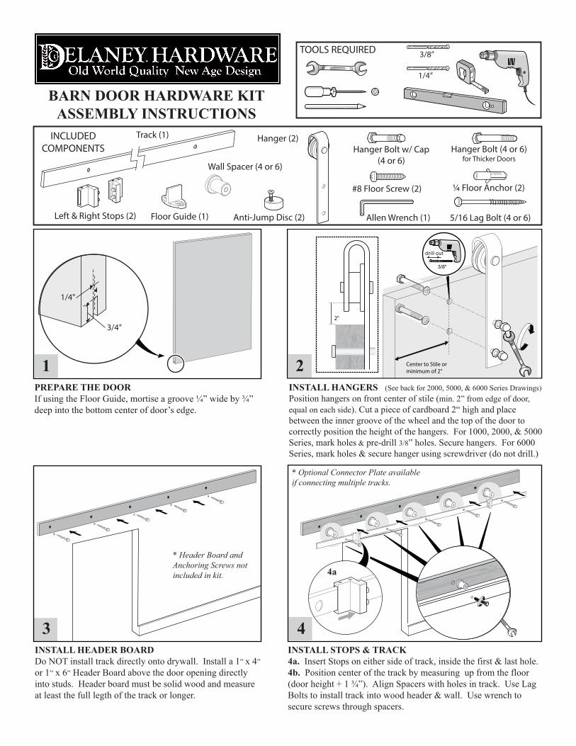
PREPARE THE DOORIf using the Floor Guide, mortise a groove ¼” wide by ¾” deep into the bottom center of door’s edge.
INSTALL HANGERS (See back for 2000, 5000, & 6000 Series Drawings)Position hangers on front center of stile (min. 2” from edge of door, equal on each side). Cut a piece of cardboard 2“ high and place between the inner groove of the wheel and the top of the door to correctly position the height of the hangers. For 1000, 2000, & 5000 Series, mark holes & pre-drill 3/8” holes. Secure hangers. For 6000 Series, mark holes & secure hanger using screwdriver (do not drill.)
INSTALL HEADER BOARDDo NOT install track directly onto drywall. Install a 1” x 4” or 1” x 6” Header Board above the door opening directly into studs. Header board must be solid wood and measure at least the full legth of the track or longer.
INSTALL STOPS & TRACK4a. Insert Stops on either side of track, inside the first & last hole. 4b. Position center of the track by measuring up from the floor (door height + 1 ¾”). Align Spacers with holes in track. Use Lag Bolts to install track into wood header & wall. Use wrench to secure screws through spacers.
4
1
3
4a
4b
INCLUDEDCOMPONENTS
BARN DOOR HARDWARE KITASSEMBLY INSTRUCTIONS
* Optional Connector Plate available if connecting multiple tracks.
TOOLS REQUIRED
1/4”
3/8”
* Header Board and Anchoring Screws not included in kit.
Center to Stile orminimum of 2"
2"
2
drill out
3/8"

INSTALLING THE ANTI-JUMP DISCSPosition each anti-jump disc at least 1” from the edge of the hangers. Tighten slightly to secure in place.
HANG THE DOOR Place assembled door on secured track. Tighten the anti-jump discs. Slide door from open to close to ensure all parts are operating smoothly. Secure stops in desired positions with allen wrench.
INSTALLING FLOOR DOOR GUIDE (Optional)Once the door is plumb, place the floor door guide inside the groove and line up close to the door opening. Slide the door from open to close to insure working order. Mark holes with a pencil. Pre-drill ¼” holes. If mounting into a concrete floor, use provided anchors.
5 6
7
1 3/16"
1/4"
BARN DOOR HARDWARE KITASSEMBLY INSTRUCTIONS
COMPLETED DOOR WITH BARN DOOR KIT **Note that these instructions depict the installation of Delaney Hardware 1000 Series Barn Door Kits. While hanger styles may differ, the same basic instructions will apply.
For questions about installation, please visit
www.delaneyinc.com/barndoorinstructions.asp
Or call (800) 952-4430
Step 2For the 2000, 5000, and 6000 Series, please refer to the following images for Step 2 of the instructions.