basic electronic experiments - electronics · pdf fileintroduction to basic components welcome...
TRANSCRIPT

BASICELECTRONIC
EXPERIMENTSMODEL PK-101
Perform 50Experiments!
Build an Electronic Key-board, Electronic Kazoo,Battery Tester, FingerTouch Lamp, Burglar andWater Alarms, a Siren, aMagnetic Bridge, and awhole lot more! Nosoldering or tools required,all parts are included!
(Requires a breadboard anda 9V battery or power supply.)
TRANSFORMS ANY STANDARDBREADBOARD INTO AN ELECTRONIC
LEARNING CENTER!
Copyright © 2012, 1999 by ELENCO® All rights reserved. Revised 2012 REV-G 753064No part of this book shall be reproduced by any means; electronic, photocopying, or otherwise without written permission from the publisher.
ELENCO®

2
Introduction to Inductors and Transformers 40Test Your Knowledge #2 41
Experiment #27: The Magnetic Bridge 42 Experiment #28: The Lighthouse 43 Experiment #29: Electronic Sound 44Experiment #30: The Alarm 46 Experiment #31: Morse Code 47 Experiment #32: Siren 48 Experiment #33: Electronic Rain 49 Experiment #34: The Space Gun 50 Experiment #35: Electronic Noisemaker 51 Experiment #36: Drawing Resistors 52Experiment #37: Electronic Kazoo 54Experiment #38: Electronic Keyboard 55 Experiment #39: Fun with Water 56 Experiment #40: Blinking Lights 57 Experiment #41: Noisy Blinker 58 Experiment #42: One Shot 59Experiment #43: Alarm With Shut - Off Timer 60Experiment #44: The Flip - Flop 61 Experiment #45: Finger Touch Lamp With Memory 62Experiment #46: This OR That 63 Experiment #47: Neither This NOR That 64 Experiment #48: This AND That 65Experiment #49: Audio NAND, AND 66Experiment #50: Logic Combination 67
Test Your Knowledge #3 68 Troubleshooting Guide 68 Definition of Terms 69
Parts List Page 3Answers to Quizzes 3Introduction to Basic Components 4
Experiment #1: The Light Bulb 8More About Resistors 10
Experiment #2: Brightness Control 12 Experiment #3: Resistors in Series 13 Experiment #4: Parallel Pipes 14Experiment #5: Comparison of Parallel Currents 15Experiment #6: Combined Circuit 16Experiment #7: Water Detector 17
Introduction to Capacitors 18Experiment #8: Slow Light Bulb 20 Experiment #9: Small Dominates Large 21 Experiment #10: Large Dominates Small 22Experiment #11: Make Your Own Battery 23
Test Your Knowledge #1 24 Introduction to Diodes 24
Experiment #12: One - Way Current 25 Experiment #13: One - Way Light Bulbs 26
Introduction to Transistors 27 Experiment #14: The Electronic Switch 28 Experiment #15: The Current Amplifier 28Experiment #16: The Substitute 29 Experiment #17: Standard Transistor Biasing Circuit 30 Experiment #18: Very Slow Light Bulb 31Experiment #19: The Darlington 32 Experiment #20: The Two Finger Touch Lamp 32 Experiment #21: The One Finger Touch Lamp 33 Experiment #22: The Voltmeter 34 Experiment #23: 1.5 Volt Battery Tester 36 Experiment #24: 9 Volt Battery Tester 37 Experiment #25: The Battery Immunizer 38 Experiment #26: The Anti-Capacitor 39
TABLE OF CONTENTS
In this booklet you will learn:• The basic principles of electronics.• How to build circuits using a breadboard. • How all of the basic electronic components work and how to read their values. • How to read electronic schematics.• How to design and troubleshoot basic electronic circuits. • How to change the performance of electronic circuits by changing component values within the circuit.
THE EXPERIMENTS IN THIS BOOKLET REQUIRE A BREADBOARD ORCAN BE DONE ON THE ELENCO® XK-150, XK-550, OR XK-700 TRAINERS.

PARTS LIST
Quantity Part Number Description r 1 134700 470Ω Resistor, 0.25W r 1 141000 1kΩ Resistor, 0.25W r 1 143300 3.3kΩ Resistor, 0.25W r 1 151000 10kΩ Resistor, 0.25W r 1 153300 33kΩ Resistor, 0.25W r 1 161000 100kΩ Resistor, 0.25Wr 1 171000 1MΩ Resistor, 0.25Wr 1 191549 50kΩ Variable Resistor, lay-down, with dialr 1 235018 0.005μF Disc Capacitor r 1 244780 0.047μF Disc Capacitor r 1 271045 10μF Electrolytic Capacitorr 1 281044 100μF Electrolytic Capacitorr 1 314148 Diode, 1N4148 r 3 323904 Transistor, NPN, 2N3904 r 2 350002 Light Emitting Diodes (LEDs) r 1 442100 Transformer r 1 540100 Switch, push-buttonr 1 590098 9V Battery Clip r 1 590102 Speaker, 8Ω, 0.25 Watt, with wires addedr 1 - Wires Bag
QUIZ ANSWERS
First Quiz: 1. electrons; 2. short; 3. battery; 4. increase; 5. insulators, conductors; 6. decreases, increases; 7. decreases;8. voltage; 9. alternating, direct; 10. increases, decreases.
Second Quiz: 1. reverse; 2. LEDs; 3. amplifier; 4. integrated; 5. saturated; 6. direct, alternating; 7. decreases, increases;8. magnetic; 9. increases; 10. twice
Third Quiz: 1. feedback; 2. air, pressure; 3. decreases; 4. OR; 5. NAND
3

INTRODUCTION TO BASIC COMPONENTS
Welcome to the exciting world of Electronics! Before starting the first experiment, let’s learn about some of the basicelectronic components. Electricity is a flow of sub-atomic (very, very, very, small) particles, called electrons. Theelectrons move from atom to atom when an electrical charge is applied across the material. Electronics will be easier tounderstand if you think of the flow of electricity through circuits as water flowing through pipes (this will be referred to asthe water pipe analogy).
Wires: Wires can be thought of as large, smooth pipes that allow water to pass through easily. Wires are made of metals,usually copper, that offer very low resistance to the flow of electricity. When wires from different parts of a circuit connectaccidentally we have a short circuit or simply a short. You probably know from the movies that this usually means trouble.You must always make sure that the metal from different wires never touches except at springs where the wires areconnecting to each other. The electric current, expressed in amperes (A, named after Andre Ampere who studied therelationship between electricity and magnetism) or milliamps (mA, 1/1000 of an ampere), is a measure of how fastelectrons are flowing in a wire just as a water current describes how fast water is flowing in a pipe.
Batteries and Generators: To make water flow through a pipe we need a pump. To make electricity flow through wires,we use a battery or a generator to create an electrical charge across the wires. A battery does this by using a chemicalreaction and has the advantage of being simple, small, and portable. If you move a magnet near a wire then electricity willflow in the wire. This is done in a generator. The electric power companies have enormous generators driven by steam orwater pressure to produce electricity for your home.
The voltage, expressed in volts (V, and named after Alessandro Volta who invented the battery in 1800), is a measure ofhow strong the electric charge from your battery or generator is, similar to the water pressure. Your PK-101 may be usedwith either a 9V battery or the adjustable power supply that is part of the XK-150, XK-550, and XK-700 Trainers. A powersupply converts the electricity from your electric company into a simple form that can be used in your PK-101. If using thepower supply, then adjust it for 9V. (This manual will usually refer to the battery, this is also meant to refer to the 9V powersupply if you are using that instead). Notice the “+” and “–” signs on the battery. These indicate which direction the batterywill “pump” the electricity, similarly to how a water pump can only pump water in one direction. The 0V or “–” side of thebattery is often referred to as “ground”. Notice that just to the right of the battery pictured below is a symbol, the samesymbol you see next to the battery holder. Engineers are not very good at drawing pictures of their parts, so whenengineers draw pictures of their circuits they use symbols like this to represent them. It also takes less time to draw andtakes up less space on the page. Note that wires are represented simply by lines on the page.
The Switch: Since you don’t want to waste water when you are not using it, you have a faucet or valve to turn the wateron and off. Similarly, you use a switch to turn the electricity on and off in your circuit. A switch connects (the “closed” or“on” position) or disconnects (the “open” or “off” position) the wires in your circuit. As with the battery, the switch isrepresented by a symbol, shown below on the right.
4
PIPE WIRE
9V
BATTERYWATER PUMP
VALVE SWITCH
Symbol for BATTERY
Symbol for SWITCH
You have been given one of the two above switches.
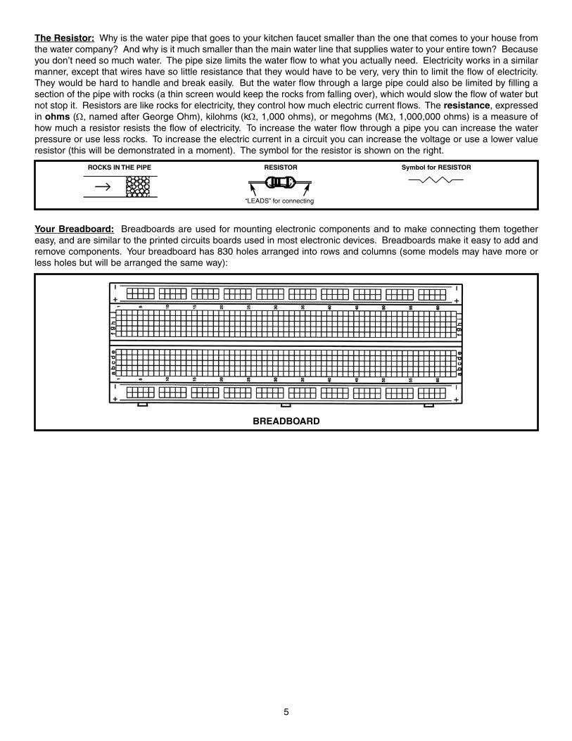
The Resistor: Why is the water pipe that goes to your kitchen faucet smaller than the one that comes to your house fromthe water company? And why is it much smaller than the main water line that supplies water to your entire town? Becauseyou don’t need so much water. The pipe size limits the water flow to what you actually need. Electricity works in a similarmanner, except that wires have so little resistance that they would have to be very, very thin to limit the flow of electricity.They would be hard to handle and break easily. But the water flow through a large pipe could also be limited by filling asection of the pipe with rocks (a thin screen would keep the rocks from falling over), which would slow the flow of water butnot stop it. Resistors are like rocks for electricity, they control how much electric current flows. The resistance, expressedin ohms (Ω, named after George Ohm), kilohms (kΩ, 1,000 ohms), or megohms (MΩ, 1,000,000 ohms) is a measure ofhow much a resistor resists the flow of electricity. To increase the water flow through a pipe you can increase the waterpressure or use less rocks. To increase the electric current in a circuit you can increase the voltage or use a lower valueresistor (this will be demonstrated in a moment). The symbol for the resistor is shown on the right.
Your Breadboard: Breadboards are used for mounting electronic components and to make connecting them togethereasy, and are similar to the printed circuits boards used in most electronic devices. Breadboards make it easy to add andremove components. Your breadboard has 830 holes arranged into rows and columns (some models may have more orless holes but will be arranged the same way):
5
Symbol for RESISTORRESISTORROCKS IN THE PIPE
BREADBOARD
“LEADS” for connecting

6
The holes are connected together as follows:
• There are many columns of 5 holes each. The 5 holes within each column are electrically connected together, but thecolumns are not electrically connected to each other. This makes 126 columns of 5 holes each. Note that “electricallyconnected together” means that there is a wire within the breadboard connecting the 5 holes.
• All holes in the rows marked with a blue “–” or a red “+” are electrically connected together, but none of these rows areelectrically connected to each other. This makes 6 rows of 100 holes. The red “+” holes will usually be used for your “+”battery or power supply connections and the blue “–” holes will usually be used for your ground (“–” battery or powersupply) connections.
Inserting Parts into the Breadboard: To insert components into the breadboard, keep their pins straight and gently pushinto the holes. If the pins get bent and become difficult to insert, they can be straightened with a pliers. Always make surecomponents do not touch each other.
INSERTING PARTS
BREADBOARD CONNECTIONS
Electrolytic capacitors have a positiveand a negative electrode. The negativelead is indicated on the packaging by astripe with minus signs and possiblyarrowheads.
Warning:If the capacitor isconnected withincorrect polarity,it may heat up andeither leak, orcause thecapacitor toexplode.
PolarityMarking

7
Before You Begin: The rows of the breadboard are marked with letters (some rows are marked “+” and “–”) and thecolumns are marked by numbers, this allows each hole to be identified individually. We will use this notation to smoothlyguide you through the experiments. Depending on the size of your breadboard, several sets of rows may be marked withthe same letter, but only a portion of the overall breadboard will be used so this will not be a problem. The row and columnnumbers will be expressed as a row/column number. For example, a connection at row b, column 26 will be called holeb26. And a connection at row +, column 3 will be called hole (+)3. Some examples of this are shown below:
After using your kit for a while, some of the wire ends may break off. If so, you should remove about 3/8 inch of insulationfrom the broken end with a wire stripper or scissors.
column 26
hole (-)7
row b
column 3
row (+)
hole h6
hole e15
IDENTIFYING HOLE LOCATIONS

8
EXPERIMENT #1: The Light Bulb
First, decide if you will use a 9V battery (alkaline is best) or the adjustable power supply that is part of the XK-150, XK-550,and XK-700 Trainers. If using a battery then snap it into its clip. Always remove the battery from its clip if you won’t be usingyour PK-101 for a while. Insert the red wire from the battery clip into hole j4 and the black wire into hole (–)3.
If using the adjustable power supply then turn it on and adjust it for 9V. Connect a wire from the positive adjustable voltageoutput to hole j4 and another wire from the power supply negative output (ground) to hole (–)3.
Let’s introduce another component, the LED (light emitting diode). It is shown below, with its symbol. We’ll explain what itdoes in just a few moments.
Now insert the components for this circuit into your breadboard according to the list below (the first item is for thebattery/power supply which you already did above), which we’ll call the Wiring Checklist. When you’re finished your wiringshould look like the diagram shown at right:
1 2
Parts Needed:
• a 9V battery or power supply • one Switch• one 10kΩ resistor
(marked brown-black-orange-gold, in that order)• one LED• 2 wires
Wiring Checklist:
Insert red battery wire or positive power supply intohole j4 and black battery wire or negative powersupply (ground) into hole (–)3.
Insert switch into holes f4 and f5.
Insert the 10kΩ resistor into holes j5 and j9.
Insert the LED into holes g20 and g21. NOTE: The“flat” side of the LED (as shown on the pictureabove, and usually the shorter wire) goes into g21.
Insert a short wire between holes h9 and j20.
Insert a short wire between holes f21 and (–)21.
Be sure all your wires are securely in place and notloose. Also make sure the metal into each hole isnot touching any other metal, including other partsof the same component.
9VBATTERY
POWERSUPPLY
+9V
0V (GROUND)
(BLACK)
(RE
D)
10kΩ
RESISTORLED
(symbol shows flatside is on right)
SWITCH WIRES
WIRING DIAGRAM
LED
Flat
Symbol for LED

The Wiring Checklist and Wiring Diagram showyou ONE way of connecting the circuitcomponents using your breadboard. There aremany other ways that are also correct. Theimportant thing is that the electrical connectionsare as shown in the schematic (see below).
Press the switch and the LED lights up, and turns off when you release the switch. The LED converts electrical energyinto light, like the light bulbs in your home. You can also think of an LED as being like a simple water meter, since as theelectric current increases in a wire the LED becomes brighter. It is shown again here, with its symbol.
Take a look at the water diagram that follows. It shows the flow of water from the pump through the faucet, the small pipe,the water meter, the large pipes, and back to the pump. Now compare it to the electrical diagram next to it, called aschematic. Schematics are the “maps” for electronic circuits and are used by all electronic designers and technicians oneverything from your PK-101 to the most advanced supercomputers. They show the flow of electricity from the batterythrough the switch, the resistor, the LED, the wires, and back to the battery. They also use the symbols for the battery,switch, resistor, and LED that we talked about. Notice how small and simple the schematic looks compared to the waterdiagram; that is why we use it.
Now you will see how changing the resistance in the circuit increases the current through it. Press the switch again andobserve the brightness of the LED. Now remove the 10kΩ resistor and replace it with a 1kΩ resistor (marked brown-black-red-gold, in that order) in the same holes (j5 and j9). Press the switch. The LED is brighter now, do you understand why?We are using a lower resistance (less rocks), so there is more electrical current flowing (more water flows), so the LED isbrighter. Now replace the 1kΩ resistor with the 100kΩ resistor (marked brown-black-yellow-gold, in that order) and pressthe switch again. The LED will be on but will be very dim (this will be easier to see if you wrap your hand near the LED tokeep the room lights from shining on it).
Well done! You’ve just built YOUR first electronic circuit!
9
WATER METER LED
Flat
Symbol for LED
Example of Inserting the Resistor

10
MORE ABOUT RESISTORS
Ohm’s Law: You just observed that when you have less resistance in the circuit, more current flows (making the LEDbrighter). The relationship between voltage, current, and resistance is known as Ohm’s Law (after George Ohm whodiscovered it in 1828):
VoltageCurrent = ____________
Resistance
Resistance: Just what is Resistance? Take your hands and rub them together very fast. Your hands should feel warm.The friction between your hands converts your effort into heat. Resistance is the electrical friction between an electriccurrent and the material it is flowing through; it is the loss of energy from electrons as they move between atoms of thematerial. Resistors are made using carbon and can be constructed with different resistive values, such as the seven partsincluded in your PK-101. If a large amount of current is passed through a resistor then it will become warm due to theelectrical friction. Light bulbs use a small piece of a highly resistive material called tungsten. Enough current is passedthrough this tungsten to heat it until it glows white hot, producing light. Metal wires have some electrical resistance, but itis very low (less than 1Ω per foot) and can be ignored in almost all circuits. Materials such as metals which have lowresistance are called conductors. Materials such as paper, plastic, and air have extremely high values of resistance andare called insulators.
Resistor Color Code: You are probably wondering what the colored bands on the resistors mean. They are the methodfor marking the value of resistance on the part. The first ring represents the first digit of the resistor’s value. The secondring represents the second digit of the resistor’s value. The third ring tells you the power of ten to multiply by, (or the numberof zeros to add). The final and fourth ring represents the construction tolerance. Most resistors have a gold band for a 5%tolerance. This means the value of the resistor is guaranteed to be within 5% of the value marked. The colors below areused to represent the numbers 0 through 9.
COLOR VALUEBLACK 0 BROWN 1
RED 2 ORANGE 3 YELLOW 4 GREEN 5 BLUE 6
VIOLET 7 GRAY 8 WHITE 9
Use the color code to check the values of the seven resistors included in your PK-101, and compare to the list below:
YELLOW - VIOLET - BROWN - GOLD is 470 Ω with 5% toleranceBROWN - BLACK - RED - GOLD is 1,000 Ω (or 1 kΩ) with 5% toleranceORANGE - ORANGE - RED - GOLD is 3,300 Ω (or 3.3 kΩ) with 5% toleranceBROWN - BLACK - ORANGE - GOLD is 10,000 Ω (or 10 kΩ) with 5% toleranceORANGE - ORANGE - ORANGE - GOLD is 33,000 Ω (or 33 kΩ) with 5% toleranceBROWN - BLACK - YELLOW - GOLD is 100,000 Ω (or 100 kΩ) with 5% toleranceBROWN - BLACK - GREEN - GOLD is 1,000,000 Ω (or 1 MΩ) with 5% tolerance
RED ORANGE
VIOLET GOLD
27 X 10,000 = 27,000 Ω, with 5% Tolerance
Example of Color Code

The Variable Resistor: We talked about how a switch is used to turn the electricity on and off just like a valve is used toturn the water on and off. But there are many times when you want some water but don’t need all that the pipe can deliver,so you control the water by adjusting an opening in the pipe with a faucet. Unfortunately, you can’t adjust the thickness ofan already thin wire. But you could also control the water flow by forcing the water through an adjustable length of rocks,as in the rock arm shown below.
In electronics we use a variable resistor. This is a normal resistor (50kΩ in your PK-101) with an additional arm contactthat can move along the resistive material and tap off the desired resistance.
The dial on the variable resistor moves the arm contact and sets the resistance between the left and center pins. Theremaining resistance of the part is between the center and right pins. For example, when the dial is turned fully to the left,there is minimal resistance between the left and center pins (usually 0Ω) and maximum resistance between the center andright pins. The resistance between the left and right pins will always be the total resistance, (50kΩ for your part).
Now let’s demonstrate how this works.
11
ROCKARM
VARIABLE RESISTOR
Symbol for VARIABLE RESISTOR
CENTER PIN
RIGHT PINLEFT PIN
WIPER CONTACT
INSULATING BASE MATERIAL
LEADS
MOVABLEARM
THIN LAYER OFRESISTIVE MATERIAL
STATIONARY CONTACT
VARIABLE RESISTOR

WATER DIAGRAM
EXPERIMENT #2: THE BRIGHTNESS CONTROL
Remove the 10kΩ resistor used in Experiment #1; the other parts are used here. Insert the new parts according to theWiring Checklist below. Press the switch and the LED lights up (it may be dim). Now hold the switch closed with one handand turn the dial on the variable resistor with the other. When the dial is turned to the left, the resistance in the circuit islow and the LED is bright because a large current flows. As you turn the dial to the right the resistance increases and theLED will become dim, just as forcing the water through a section of rocks would slow the water flow and lower the readingon your water meter.
You may be wondering what the 1kΩ resistor is doing in the circuit. If you set the dial on the variable resistor for minimumresistance (0Ω) then Ohm’s Law tells us the current will be very large - and it might damage the LED (think of this as avery powerful water pump overloading a water meter). So the 1kΩ was put in to limit the current while having little effecton the brightness of the LED.
Now remove the wire from c14 and connect it to c16. Do you know what will happen now? Close the switch and you willsee that as you turn the dial from the left to the right the LED goes from very dim to very bright (the opposite of whenconnected to c14), because you are decreasing the resistance between the center and right pins.
Now remove the 1kΩ resistor from hole j15 and insert it into hole c14 (the other end stays in j5). What do you think willhappen? Close the switch and turn the dial on the variable resistor. The LED is dim and turning the resistor dial won’tmake it any brighter. As discussed above, the resistance between the left and right pins is always 50kΩ and the part actsjust like one of the other resistors in your PK-101.
SCHEMATIC
Variable resistors like this one are used in the light dimmers youmay have in your house, and are also used to control the volumein your radio, your TV, and many electronic devices.
Parts Needed:• a 9V battery or power supply• Switch• one 1kΩ resistor (marked brown-black-red-gold)
• 50kΩ variable resistor
• one LED• 2 wires
Wiring Checklist ( indicates same position as lastexperiment):
Insert red battery wire or positive power supply into hole j4and black battery wire or negative power supply (ground) intohole (–)3.Insert switch into holes f4 and f5. Insert the LED into holes g20 and g21 (“flat” side goes into g21). Insert a short wire between holes f21 and (–)21. Insert the 1kΩ resistor into holes j5 and j15.
Insert the 50kΩ variable resistor into holes e14, g15, and e16.It may be a tight fit, carefully press it in slowly. Insert a short wire between holes c14 and j20.
Be sure all your wires are securely in place and not loose. Alsomake sure the metal into each hole is not touching anyother metal, including other parts of the same component.
9VBATTERY
POWERSUPPLY
+9V 0V
(BLACK)
(RE
D)
1kΩ
RESISTOR
LED(symbol showsflat side is on
right)
SWITCH WIRES
WIRING DIAGRAM
50kΩVARIABLERESISTOR
12

EXPERIMENT #3: RESISTORS IN SERIES
Remove the resistors used in Experiment #2; the other parts are used here. Insert the new parts according to the WiringChecklist and press the switch. The LED is on but is very dim (this will be easier to see if you wrap your hand near theLED to keep the room lights from shining on it). Take a look at the schematic. There is a low 3.3kΩ resistor and a high100kΩ resistor in series (one after another). Since the LED is dimly lit, we know that the larger 100kΩ must be controllingthe current. You can think of this as where two sections of the pipe are filled with rock, if one section is much longer thanthe other then it controls the water flow. If you had several rock sections of different lengths then it is easy to see that thesewould add together as if they were one longer section. The total length is what matters, not how many sections the rockis split into. The same is true in electronics - resistors in series add together to increase the total resistance for thecircuit. (In our circuit the 3.3kΩ and 100kΩ resistors add up to 103.3kΩ).
To demonstrate this, remove the 100kΩ resistor and insert the 10kΩ in the same holes, press the switch; the LED shouldbe easy to see now (total resistance is now only 13.3kΩ). Next, remove the 10kΩ resistor and replace it with the 1kΩ. TheLED is now bright, but not as bright as when you used the 1kΩ in Experiment #1. Why? Because now the 3.3kΩ is thelarger resistor (total resistance is 4.3kΩ).
Also, in Experiment #2 you saw how the 1kΩ resistor would dominate the circuit when the variable resistor was set for 0Ωand how the variable resistor would dominate when set for 50kΩ.
Parts Needed:• a 9V battery or power supply • Switch• one 1kΩ resistor (brown-black-red-gold)
• one 3.3kΩ resistor (orange-orange-red-gold)
• one 10kΩ resistor (brown-black-orange-gold)
• one 100kΩ resistor (brown-black-yellow-gold)
• one LED• 1 wire
Wiring Checklist ( indicates same position aslast experiment):
Insert red battery wire or positive power supply intohole j4 and black battery wire or negative powersupply (ground) into hole (–)3. Insert switch into holes f4 and f5. Insert the LED into holes g20 and g21 (“flat” sidegoes into g21). Insert a short wire between holes f21 and (–)21. Insert the 3.3kΩ resistor into holes i5 and i12.
Insert the 100kΩ resistor into holes j12 and j20(avoid touching other components).
SCHEMATIC
WATER DIAGRAM
9VBATTERY
POWERSUPPLY
+9V 0V
(BLACK)
(RE
D)
3.3kΩ
RESISTORS
LED(symbol shows flat
side is on right)
SWITCH WIRE
WIRING DIAGRAM
100kΩ
13

14
EXPERIMENT #4: PARALLEL PIPES
Remove the resistors used in Experiment #3; the other parts are used here. Insert the new parts according to the WiringChecklist. Take a look at the schematic. There is a low 3.3kΩ resistor and a high 100kΩ resistor in parallel (connectedbetween the same points in the circuit). How bright do you think the LED will be? Press the switch and see if you are right.The LED is bright, so most of the current must be flowing through the smaller 3.3kΩ resistor. This makes perfect sensewhen we look at the water diagram, with most of the water flowing through the pipe with less rocks. In general, the morewater pipes (or resistors) there are in parallel, the lower the total resistance is and the more water (or current) will flow.The relationship is more complicated than for resistors in series and is given here for advanced students:
R1 x R2
R Parallel = ______________
R1 + R2
For two 10kΩ resistors in parallel, the result would be 5kΩ. The 3.3kΩ and 100kΩ in parallel in our circuit now give thesame LED brightness as a single 3.2kΩ resistor.
To demonstrate this, remove the 100kΩ resistor and replace it with the 10kΩ (in the same holes); press the switch and theLED should be just as bright. The total resistance is now only 2.5kΩ, but your eyes probably won’t notice much differencein LED brightness. Now remove the 10kΩ and replace it with the 1kΩ; press the switch. The total resistance is now only770Ω, so the LED should now be much brighter.
Parts Needed:• a 9V battery or power supply • Switch• one 1kΩ resistor (brown-black-red-gold)
• one 3.3kΩ resistor (orange-orange-red-gold)
• one 10kΩ resistor (brown-black-orange-gold)
• one 100kΩ resistor (brown-black-yellow-gold)
• one LED• 2 wires
Wiring Checklist ( indicates same position as lastexperiment):
Insert red battery wire or positive power supply (P. S.) into j4 andblack battery wire or negative power supply (ground) into (–)3. Insert switch into f4 and f5. Insert the LED into g20 and g21 (“flat” side goes into g21). Insert a short wire between f21 and (–)21. Insert the 3.3kΩ resistor into i5 and i12.
Insert the 100kΩ resistor into j5 and j12.
Insert a short wire between h12 and j20.
9VBATTERYor POWER
SUPPLY
+9V
0V
3.3KΩ
WIRING DIAGRAM
100KΩ
Note: From now on there will be less description for frequently used parts.

15
EXPERIMENT 5: COMPARISON OF PARALLEL CURRENTS
Since we have two resistors in parallel and a second LED that is not being used, let’s modify the last circuit to match theschematic below. It’s basically the same circuit but instead of just parallel resistors there are parallel resistor-LED circuits.Remove the resistors used in Experiment #4; the other parts are used here. Insert the new parts according to the WiringChecklist. Replace the 100kΩ resistor with several values as before (such as 1kΩ, 10kΩ, and others if you wish), pressingthe switch and observing the LEDs each time. The brightness of the right LED will not change, but the brightness of theleft LED will depend on the resistor value you placed in series with it.
Parts Needed:• a 9V battery or power supply • Switch• one 3.3kΩ resistor (orange-orange-red-gold)
• one 100kΩ resistor (brown-black-yellow-gold)
• 2 LEDs• 4 wires
Wiring Checklist (þ indicates same position as last experiment):Insert red battery wire or positive P. S. into j4 and black battery wire or negative P. S. (ground) into (–)3.Insert switch into f4 and f5. The switch may be a tight fit, carefully press it in slowly.Insert an LED into g20 and g21 (“flat” side goes into g21).Insert a short wire between f21 and (–)21.Insert the 100kΩ resistor into j5 and j12.
Insert a short wire between h12 and j20.Insert the 3.3kΩ resistor into i5 and j10.
Insert a short wire between g10 and j23.Insert an LED into g23 and g24 (“flat” side goes into g24).Insert a short wire between f24 and (–)24.
+9V
3.3kΩ
100kΩ
9VBATTERYor POWER
SUPPLY
Both LEDshave flat sideon right

16
EXPERIMENT #6: COMBINED CIRCUIT
Let’s combine everything we’ve done so far. Remove the resistors used in Experiment #3; the other parts are used here.Insert the new parts and wires according to the Wiring Checklist. Before pressing the switch, take a look at the schematicand think about what will happen as you turn the dial on the variable resistor (we’ll abbreviate this to VR). Now press theswitch with one hand and turn the dial with the other to see if you were right. As you turn the VR dial from left to right theleft LED will go from bright to very dim and the right LED will go from very dim to visible.
What’s happening is this: With the dial turned all the way to the left the VR is 0Ω (much smaller than the 10kΩ) so nearlyall of the current passing through the 3.3kΩ will take the VR-LED(left) path and very little will take the 10kΩ-LED(right) path.When the VR dial is turned 1/5 to the right the VR is 10kΩ (same as the other path) and the current flowing through the3.3kΩ will divide equally between the two LED paths (making them equally bright). As the VR dial is turned all the way tothe right the VR becomes a 50kΩ (much larger than the 10kΩ) and LED(left) will become dim while LED(right) gets brighter.
Now is a good time to take notes on how resistors work in series and in parallel. All electronic circuits are much largercombinations of series and parallel circuits such as these. It’s important to understand these ideas because soon we’llapply them to capacitors and inductors!
Parts Needed:• a 9V battery or power supply • Switch• one 3.3kΩ resistor (orange-orange-red-gold)
• one 10kΩ resistor (brown-black-orange-gold)
• 50kΩ variable resistor
• 2 LEDs• 3 wires
Wiring Checklist ( indicates same position as last experiment):Insert red battery wire or positive P. S. into j4 and black battery wireor negative P. S. (ground) into (–)3. Insert switch into f4 and f5. Insert an LED into g20 and g21 (“flat” side goes into g21). Insert a short wire between f21 and (–)21. Insert an LED into g23 and g24 (“flat” side goes into g24). Insert a short wire between f24 and -24. Insert the 50kΩ variable resistor into holes e14, g15, and e16. Itmay be a tight fit, carefully press it in slowly. Insert the 3.3kΩ resistor into i5 and i15.
Insert the 10kΩ resistor into j15 and j23.
Insert a short wire between c14 and j20.
+9V
3.3KΩ10KΩ
50KΩVARIABLERESISTOR

17
EXPERIMENT #7: WATER DETECTOR
You’ve seen how electricity flows through copper wires easily and how carbon resists the flow. How well does water passelectricity? Let’s find out.
Connect the parts and wires according to the Wiring Checklist and take a look at the schematic. There isn’t a switch thistime, so just disconnect one of the wires if you want to turn the circuit off. Notice that the Wiring Checklist leaves 2 wiresunconnected. The LED will be off initially (if you touch the two loose wires together then it will be on). Now take a smallcup (make sure it isn’t made of metal), fill it half way with water, and place the two unconnected wires into the water withouttouching each other. The LED should now be dimly lit, but the brightness could vary depending on your local water quality.You are now seeing a demonstration of how water conducts (passes) electricity. (A small cup of water like this may bearound 100kΩ, but depends on the local water quality). Try adding more water to the cup and see if the LED brightnesschanges (it should get brighter because we are “making the water pipe larger”). Since the LED only lights when it is inwater now, you could use this circuit as a water detector!
Now adjust the amount of water so that the LED is dimly lit. Now, watching the LED brightness, add some table salt to thewater and stir to dissolve the salt. The LED should become brighter because water has a lower electrical resistance whensalt is dissolved in it. Looking at the water pipe diagram, you can think of this as a strong cleaner dissolving paintballs thatare mixed in with the rocks. You could even use this circuit to detect salt water like in the ocean!
Parts Needed:a 9V battery or power supply one 470Ω resistor (yellow-violet-brown-gold)one 1kΩ resistor (brown-black-red-gold)one 3.3kΩ resistor (orange-orange-red-gold) one 10kΩ resistor (brown-black-orange-gold)one LED2 long wiresa glass of water and salt
+9V
1kΩ 470Ω
Wiring Checklist ( indicates same position as last experiment):Insert red battery wire or positive P. S. into j4 and black battery wireor negative P. S. (ground) into (–)3. Insert an LED into g20 and g21 (“flat” side goes into g21).
Note: Keep the switch in the breadboard (unconnected) until laterexperiments, as it can be difficult to remove and insert.
Insert the 470Ω resistor into j12 and j20.
Insert the 1kΩ resistor into i4 and i12.
Insert the 3.3kΩ resistor into h20 and (–)18.
Insert the 10kΩ resistor into f20 and (–)21.
Insert a long wire into j21 (the other end is unconnected for now).Insert a long wire into (–)25 (the other end is unconnected for now).
10kΩ
3.3k
Ω
TO GLASSOF WATER
Note: Switch is notused here but leavein for futureexperiments.

INTRODUCTION TO CAPACITORS
Capacitors: Capacitors are electrical components that can store electrical pressure (voltage) for periods of time. Whena capacitor has a difference in voltage (electrical pressure) across it, it is said to be charged. A capacitor is charged byhaving a one-way current flow through it for a short period of time. It can be discharged by letting a current flow in theopposite direction out of the capacitor. In the water pipe analogy, you may think of the capacitor as a water pipe that hasa strong rubber diaphragm sealing off each side of the pipe as shown below:
If the pipe had a plunger on one end (or a pump elsewhere in the piping circuit), as shown above, and the plunger waspushed toward the diaphragm, the water in the pipe would force the rubber to stretch out until the force of the rubberpushing back on the water was equal to the force of the plunger. You could say the pipe is charged and ready to push theplunger back. In fact if the plunger is released it will move back to its original position. The pipe will then be discharged orwith no pressure on the diaphragm.
Capacitors act the same as the pipe just described. When a voltage (electrical pressure) is placed on one side with respectto the other, electrical charge “piles up” on one side of the capacitor (on the capacitor “plates”) until the voltage pushingback equals the voltage applied. The capacitor is then charged to that voltage. If the charging voltage was then decreasedthe capacitor would discharge. If both sides of the capacitor were connected together with a wire then the capacitor wouldrapidly discharge and the voltage across it would become zero (no charge).
What would happen if the plunger in the drawing above was wiggled in and out many times each second? The water inthe pipe would be pushed by the diaphragm and then sucked back by the diaphragm. Since the movement of the water(current) is back and forth (alternating) it is called an alternating current or AC. The capacitor will therefore pass analternating current with little resistance. When the push on the plunger was only toward the diaphragm, the water on theother side of the diaphragm moved just enough to charge the pipe (a transient or temporary current). Just as the pipeblocked a direct push, a capacitor blocks a direct current (DC). Current from a battery is an example of direct current. Anexample of alternating current is the 60 cycle (60 wiggles per second) current from the electrical outlets in the walls of yourhouse.
Construction of Capacitors: If the rubber diaphragm is made very soft it will stretch out and hold a lot of water but willbreak easily (large capacitance but low working voltage). If the rubber is made very stiff it will not stretch far but will beable to withstand higher pressure (low capacitance but high working voltage). By making the pipe larger and keeping therubber stiff we can achieve a device that holds a lot of water and withstands high pressure (high capacitance, high workingvoltage, large size). So the pipe size is determined by its capacity to hold water and the amount of pressure it can handle.These three types of water pipes are shown below:
18
SOFTRUBBER
LARGE CAPACITYLOW PRESSURE
STIFFRUBBER
LOW CAPACITY BUTCAN WITHSTANDHIGH PRESSURE
STIFFRUBBER
HIGH CAPACITY ANDCAN WITHSTANDHIGH PRESSURE
TYPES OF WATER PIPES
RUBBER DIAPHRAGMSEALING CENTER OF PIPE
PLUNGER
PIPE FILLED WITH WATER
A Rubber Diaphragm in apipe is like a Capacitor

Similarly, capacitors are described by their capacity for holding electric charge, called their Capacitance, and their abilityto withstand electric pressure (voltage) without damage. Although there are many different types of capacitors made usingmany different materials, their basic construction is the same. The wires (leads) connect to two or more metal plates thatare separated by high resistance materials called dielectrics.
The dielectric is the material that holds the electric charge (pressure), just like the rubber diaphragm holds the waterpressure. Some dielectrics may be thought of as stiff rubber, and some as soft rubber. The capacitance and workingvoltage of the capacitor is controlled by varying the number and size of metal-dielectric layers, the thickness of the dielectriclayers, and the type of dielectric material used.
Capacitance is expressed in farads (F, named after Michael Faraday whose work in electromagnetic induction led to thedevelopment of today’s electric motors and generators ), or more commonly in microfarads (μF, millionths of a farad) orpicofarads (pF, millionths of a microfarad). Almost all capacitors used in electronics vary from 1pF to 1,000μF.
Your PK-101 includes two electrolytic (10μF and 100μF) and two disc (0.005μF and 0.047μF) capacitors. (Mylar capacitorsmay have been substituted for the disc ones, their construction and performance is similar). Electrolytic capacitors (usuallyreferred to as lytics) are high capacitance and are used mostly in power supply or low frequency circuits. Their capacitanceand voltage are usually clearly marked on them. Note that these parts have “+” and “–” polarity (orientation) markings, thelead marked “+” should always be connected to a higher voltage than the “–” lead (all of your Wiring Diagrams account for this).
Disc capacitors are low capacitance and are used mostly in radio or high frequency applications. They don’t have polaritymarkings (they can be hooked up either way) and their voltage is marked with a letter code (most are 50V). Their value isusually marked in pF with a 3 digit code similar to the stripes used on resistors. The first 2 digits are the first 2 digits of thecapacitor’s value and the third digit tells the power of 10 to multiply by (or the number of zeros to add). For example, the0.005μF (5,000pF) and .047μF (47,000pF) disc capacitors in your PK-101 are marked 502 and 473.
Capacitors have symbols as follows:
19
DIELECTRIC
METAL PLATE
LEAD 2
LEAD 1
Constructionof a Capacitor
SOFT DIAPHRAGM
STIFF DIAPHRAGM
ELECTROLYTIC CAPACITOR
DISC CAPACITOR
Symbol forDISC CAPACITOR
Symbol forELECTROLYTIC CAPACITOR
(–) (+)

EXPERIMENT #8: SLOW LIGHT BULB
Starting with this experiment, we will no longer show you the Parts List or the Wiring Checklist. Refer back to the previousexperiments if you feel you need more practice in wiring the circuits. Refer back to page 10 if you need to review the resistorcolor code. Connect the circuit according to the schematic and Wiring Diagram and press the switch several times. Youcan see it takes time to charge and discharge the large capacitor because the LED lights up and goes dim slowly. Replacethe 3.3kΩ resistor with the 1kΩ resistor; now the charge time is faster but the discharge time is the same. Do you knowwhy? When the switch is closed the battery charges the capacitor through the 1kΩ resistor and when the switch is openedthe capacitor discharges through the 10kΩ, which has remained the same. Now replace the 100μF capacitor with the 10μF.Both the charge and discharge times are now faster since there is less capacitance to charge up. If you like you mayexperiment with different resistors in place of the 1kΩ and 10kΩ. If you observe the LED carefully, you might start tosuspect the relationship between the component values and the charging and discharging times - the charge/dischargetimes are proportional to both the capacitance and the resistance in the charge/discharge path!
A simple circuit like this is used to slowly light or darken a room, such as a movie theater.
20
+9V3.3kΩ 10kΩ
100μF
CAPACITOR
+
-

EXPERIMENT #9: SMALL DOMINATES LARGE - CAPACITORS IN SERIES
Take a look at the schematic, it is almost the same circuit as the last experiment except that now there are two capacitorsin series. What do you think will happen? Connect the circuit according to the schematic and Wiring Diagram and pressthe switch several times to see if you are right.
Looking at the water diagram and the name of this experiment should have made it clear - the smaller 10μF will dominate(control) the response since it will take less time to charge up. As with resistors, you could change the order of the twocapacitors and would still get the same results (try this if you like). Notice that while resistors in series add together tomake a larger circuit resistance, capacitors in series combine to make a smaller circuit capacitance. Actually, capacitorsin series combine the same way resistors in parallel combine (using the same mathematical relationship given inExperiment 4). For this experiment, 10μF and 100μF in series perform the same as a single 9.1μF.
In terms of our water pipe analogy, you could think of capacitors in series as adding together the stiffness of their rubberdiaphragms.
21
+9V3.3kΩ 10kΩ
100μF
CAPACITOR
10μF
+
-
+
-

EXPERIMENT #10: LARGE DOMINATES SMALL - CAPACITORS IN PARALLEL
Now you have capacitors in parallel, and you can probably predict what will happen. If not, just think about the lastexperiment and about how resistors in parallel combine, or think in terms of the water diagram again. Connect the circuitaccording to the schematic and Wiring Diagram and press the switch several times to see.
Capacitors in parallel add together just like resistors in series, so here 10μF + 100μF = 110μF total circuit capacitance. Inthe water diagram, we are stretching both rubber diaphragms at the same time so it will take longer than to stretch eitherone by itself. If you like you may experiment with different resistor values as you did in experiment #8. Although you dohave two disc capacitors and a variable capacitor (which will be discussed later) there is no point in experimenting with themnow, their capacitance values are so small that they would act as an open switch in any of the circuits discussed so far.
22
+9V3.3kΩ 10kΩ
100μF10μF
+
-

EXPERIMENT #11: MAKE YOUR OWN BATTERY
Connect the circuit according to the schematic and Wiring Diagram. Note that one side of the battery and resistor areunconnected and there is a wire connected only to the 100μF capacitor. At this time no current will flow because nothingis connected to the battery. Now hold the loose wire and touch it to the positive battery wire and then remove it, the batterywill instantly charge the capacitor since there is no resistance (actually there is some internal resistance in the battery andsome in the wires but these are very small). The capacitor is now charged and is storing the electricity it received from thebattery. It will remain charged as long as the loose wire is kept away from any metal. Now touch the loose wire to looseside of the 3.3kΩ resistor and watch the LED. It will initially be very bright but diminishes quickly as the capacitordischarges. Repeat charging and discharging the capacitor several times. You can also discharge the 100μF in smallbursts by only briefly touching the 3.3kΩ. If you like you can experiment with using different values in place of the 3.3kΩ;lower values will make the LED brighter but it will dim faster while with higher resistor values the LED won’t be as brightbut it will stay on longer. You can also put a resistor in series with the battery when you charge the capacitor, then it willtake time to fully charge the capacitor. What do you think would happen if you used a smaller capacitor value?
When the capacitor is charged up it is storing electricity which could be used elsewhere at a later time - it is like a battery!However, an electrolytic capacitor is not a very efficient battery. Storing electric charge between the plates of a capacitoruses much more space than storing the same amount of charge chemically within a battery - compare how long the 100μFlit the LED above with how your 9V battery runs all of your experiments!
Now is a good time to take notes for yourself on how capacitors work, since next we introduce the diode.
23
+9V
3.3k
Ω
100μF
(UNCONNECTED)
(LOOSE WIRE)
(UNCONNECTED)
+
-

TEST YOUR KNOWLEDGE #1
1. __________ are the particles that flow between atoms as part of an electric current.
2. A __________ circuit occurs when wires or components from different parts of the circuit accidentally connect.
3. A __________ produces electricity using a chemical reaction.
4. To decrease the current in a circuit you may decrease the voltage or __________ the resistance.
5. Materials which have very high resistance are called __________ and materials which have very low resistance arecalled __________.
6. Adding resistors in parallel __________ the resistance while adding resistors in series _________ the resistance.
7. The electrical resistance of water __________ when salt is dissolved in it.
8. Capacitors are components that can store __________ for periods of time.
9. Capacitors have low resistance to __________ current and high resistance to __________ current.
10. Adding capacitors in parallel __________ the capacitance while adding capacitors in series __________ thecapacitance.
(Answers are on page 3)
INTRODUCTION TO DIODES
The Diode: The diode is an electronic device that allows current to flow in only one direction. In our water pipe analogy itmay be thought of as the check valve shown here:
The check valve only allows water to flow in one direction, to the right in this drawing. There is a small spring and if thewater pressure exceeds a certain level then the spring will be stretched and the valve opened. If the pressure is to flow tothe left then the plate will be pressed against the solid stop and no water will flow.
Electronic diodes are made from materials called semiconductors, so-called because they have more resistance thanmetal conductors but less than insulators. Most semiconductors are made of Silicon but Gallium Arsenide and Germaniumare also used. Their key advantage is that by using special manufacturing processes their resistance is decreased undercertain operating conditions. The manufacturing processes create two regions of permanent electrical charge, quitedifferent from charging a capacitor. While the physics of how this works is quite complicated, the effect is that once thevoltage across the diode exceeds a small turn-on level (0.7V for Silicon) the resistance of the diode becomes very low inone direction (so low in fact that the current flow must be limited by other resistances in the circuit to prevent damage tothe diode). When the diode is turned on like this we refer to it as being forward-biased. In the other direction the diodeis always a very high resistance, we call this reverse-biased. The schematic symbol, shown below, indicates that the diodewill allow current to flow from left to right but block current flow from right to left.
24
Solid Stop
Water-Tight Pivot
Movable PlateSpring
DIODE Symbol for DIODE

25
EXPERIMENT #12: ONE - WAY CURRENT
Your PK-101 includes one diode, a 1N4148, which is a standard diode widely used in industry. Connect the circuit andpress the switch, the LED lights up. The diode’s turn-on voltage of 0.7V is easily exceeded and the diode has little effecton the circuit. Now reverse the wires to the diode and try again, nothing happens. The diode is now reverse-biased andblocks current flow through the circuit, just like the plate and solid stop block the water flow in the drawing shown above.
You’ve probably noticed a similarity between the schematic symbols for the diode and the LED. Re-wire the diode back toforward-biased or remove it from the circuit and then reverse the wires to the LED. Press the switch and LED doesn’t light,do you know why?
Starting now, the equivalent water diagrams will no longer be presented.
+9V
3.3kΩ
DIODE(position side with black
stripe as shown)

26
EXPERIMENT #13: ONE-WAY LIGHT BULBS
Diodes made of Gallium Arsenide need a higher voltage across them to turn on, usually about 1.5V This turn-on energy isso high that light is generated when current flows through the diode. These diodes are the light emitting diodes that youhave been using.
To demonstrate this, connect the circuit below (note that the two LEDs will be referred to as “left” and “right”). Touch theloose wire to the battery and watch the left LED. It will be bright initially as a current flows to charge up the 100μF capacitorand then will dim as the capacitor voltage reaches the battery voltage. The right LED will not light since it is reverse-biased.Then touch the loose wire to the negative side of the battery (“ground”) and watch the right LED. It will be bright initiallyas a current flows to discharge the 100μF capacitor and then will dim as the capacitor voltage drops to zero. The left LEDwill not light since now it is reverse-biased.
As in Experiment #11, you may try different resistor values in this circuit if you like.
+9V
3.3kΩ
100μ
F
(LOOSE WIRE)
(UNCONNECTED)
(LOOSE WIRE)
“RIGHT” LED(flat side is
on right)
“LEFT” LED(flat side is
on right)
+ -

INTRODUCTION TO TRANSISTORS
The Transistor: The transistor was first developed in 1949 at Bell Telephone Laboratories, the name being derived from“transfer resistor”. It has since transformed the world. Did you ever hear of something called a vacuum tube? They arelarge and can be found in old electronic equipment and in museums. They are seldom used today and few engineers evenstudy them now. They were replaced by transistors, which are much smaller and more reliable.
The transistor is best described as a current amplifier - it uses a small amount of current to control a large amount ofcurrent. There are many different families of transistors but we will only discuss the type included in your PK-101, calledthe NPN Bipolar Junction Transistor or BJT and made of the semiconductor silicon. It has three connection points, calledthe emitter, base, and collector.
In our water pipe analogy the BJT may be thought of as the lever pivot shown here:
Notice that it includes a check valve that is connected to a lever arm. A small amount of “base current” pushes on the checkvalve which turns and opens the lever arm. But before this base current can start to flow though it must have enough waterpressure to overcome the spring in the check valve (usually 0.7V). If the base pipe is much smaller than the collector andemitter pipes, then a small base current IB flowing in will cause a large collector current IC to flow in, these will combineand exit the device as emitter current IE.
In transistors the emitter, base, and collector are different regions of permanent electrical charge, producing the effectsdescribed above for the lever pivot. The properties and uses of transistors may seem confusing at first but will becomeclear as you proceed through the experiments. All but one of the remaining experiments will use the transistor, so itsimportance to electronics should be apparent.
A key advantage of semiconductors is that several transistors can be manufactured on a single piece of silicon. This ledto the development of Integrated Circuit (IC) technology, in which careful control of complex manufacturing processes hasenabled entire circuits consisting of transistors, diodes, resistors, and capacitors to be constructed on a silicon base. SomeICs used in computers now have more than a million transistors on them. Spectacular improvements in cost, size, andreliability have been achieved as a result.
The schematic symbol for a transistor is shown below:
Note the small arrow in the emitter, this indicates which direction the current will flow through the device.
27
COLLECTOR
EMITTER
BASE
TRANSISTOR Symbol for NPN TRANSISTOR
Flat

28
EXPERIMENT #15: THE CURRENT AMPLIFIER
Connect the circuit and press the switch. The right LED in the collector path is brighter than the left LED in the base pathbecause the base current is amplified by the transistor. The current gain of a transistor varies anywhere from 10 to 1,000depending on the type of transistor, the ones in your PK-101 have a gain of about 200.
Note that the battery voltage and circuit resistance will limit the current gain. For example, if you replace the 1kΩ in thiscircuit with a 33kΩ then the current gain will only be about 3. The circuit resistances, not transistor itself, are limiting thecurrent and the transistor is said to be saturated.
EXPERIMENT #14: THE ELECTRONIC SWITCH
Your PK-101 includes three transistors which are all type 2N3904 NPN Bipolar Junction Transistors. Connect the circuitaccording to the schematic and Wiring Diagram. Although there is a closed circuit with the battery, 1kΩ, LED, andtransistor, no current will flow since the transistor is acting like an open circuit (with no base current the lever arm remainsshut). Press the switch; a base current now flows and opens the lever arm, resulting in a large collector current which lightsthe LED. The transistor is being used as an electronic switch. Although there is still a normal switch in this circuit, therecould be many electronic switches controlled by one normal switch.
+9V
10kΩ
(flat side ison left)
TRANSISTOR(Note position
of flat side)
+9V 1kΩ
(note how theLED flat sides are
positioned)
TRANSISTOR(Note position
of flat side)
100kΩ
1kΩ

EXPERIMENT #16: THE SUBSTITUTE
Look again at the water pipe analogy for the transistor, the lever pivot:
What would happen if the base and collector were connected together? Once there is enough pressure to overcome thespring in check valve DE (0.7V) there would be only slight resistance and no current gain. This situation should soundfamiliar since this is exactly how a diode operates. When the base and collector of a transistor are connected together thetransistor becomes a diode.
Connect the circuit and press the switch, the LED lights. This is the same circuit as Experiment 12, One-Way Current. Thisdemonstrates how transistors can be substituted for diodes, and this will occur in practice sometimes for manufacturingreasons.
29
+9V
3.3k
Ω (Note positionof flat sides)

30
EXPERIMENT #17: STANDARD TRANSISTOR BIASING CIRCUIT
Connect the circuit and press the switch while turning the variable resistor from right to left (from 0Ω to 50kΩ). The 100kΩand variable 50kΩ are a voltage divider that sets the voltage at the transistor base. If this voltage is less than 0.7V thenthe transistor will be off and no current will flow through the LED. As the base voltage increases above 0.7V a small basecurrent starts to flow, which is amplified to produce a larger collector current that lights the LED. As the base voltagecontinues to increase the transistor becomes saturated and the LED brightness will not increase further.
This circuit will normally be used with the voltage divider set so that the transistor is turned on but is not saturated. Althoughthis circuit does not have many applications by itself, when a small alternating current (AC) signal is applied to the basethen a larger copy of the signal will appear at the collector - a small-signal amplifier!
+9V
1kΩ
100kΩ
3.3kΩ
50kΩVARIABLERESISTOR

31
EXPERIMENT #18: VERY SLOW LIGHT BULB
Connect the circuit and press the switch, hold it down for several seconds. The LED will slowly light up. Release the switchand the LED will slowly go dark.
When you first press the switch all of the current flowing through the 100kΩ resistor goes to charge up the capacitor, thetransistor and LED will be off. When the capacitor voltage rises to 0.7V the transistor will first turn on and the LED will turnon. As the capacitor voltage continues to rise the current flow through the 470Ω resistor and into the transistor base willincrease. The current through the LED will then rise rapidly due to the transistor’s current gain.
When the switch is released the capacitor will discharge through the 470Ω resistor and the transistor base, the LED willdim as this discharge current decreases. When the capacitor voltage drops below 0.7V the transistor will turn off. If youget impatient you may touch a wire between the two capacitor springs to discharge it instantly.
Do you know how to change the capacitor charge and discharge times? The 100kΩ resistor controls the charge time, the470Ω controls the discharge, and the capacitor controls both the charge and discharge. Replace these parts with somedifferent values and observe the effects.
Compare this circuit to the one you used in Experiment 8 when we first introduced the capacitor. By adding a transistoryou can use a large resistor for a slow charge time and still have a bright LED!
+9V
470Ω
100μF
100kΩ
3.3kΩ
+
-

32
EXPERIMENT #20: THE TWO FINGER TOUCH LAMP
Take a look at the schematic. You’re probably wondering how it can work, since nothing is connected to the transistor base.It can’t, but there is another component that isn’t shown in the schematic. That component is you.
Connect the circuit according to the schematic and Wiring Diagram, including the two loose wires. Now touch the loosebattery wire with one finger and the loose transistor wire with another. The LED may be dimly lit. The problem is yourfingers aren’t making good enough electrical contact with the springs. Wet your fingers with water or saliva and touch thesprings again. The LED should be very bright now. You saw in Experiment 7 how water can conduct electricity and sinceyour body is mostly water it shouldn’t surprise you that your body can also conduct. Your body’s resistance varies a lot,but is typically a few hundred kilohms. Think of this circuit as a touch lamp since when you touch it the LED lights. Youmay have seen such a lamp in the store or already have one in your home.
(LOOSE WIRE)(LOOSE WIRE)
+9V
470Ω
3.3kΩ
(switch is left unconnectedfor future experiments)
EXPERIMENT #19: THE DARLINGTON
This circuit is very similar to the last one. Connect the components and press the switch, hold it down for several seconds.The LED will slowly light up. Release the switch and the LED stays lit.
Take a look at the schematic. All the current flowing through the emitter of the left transistor will flow to the base of theright transistor. So the current flowing into the base of the left transistor will be amplified twice, once by each transistor.This configuration is called the Darlington configuration. It has very high current gain and very high input resistance atthe base. Since there are now two transistors to turn on, the capacitor voltage must exceed 1.4V before the LED will startto light. And, since the input current to the base is so small, it will take much longer to discharge the capacitor. But thecircuit is functionally the same as Experiment 18 and the LED will eventually go dark, though it may take a few minutes.You can experiment with changing some of the component values if you like.
+9V3.3kΩ
100μF
100kΩ
470Ω
(Note positionsof flat sides)+
-

EXPERIMENT #21: THE ONE FINGER TOUCH LAMP
Actually, the touch lamps you see in stores only need to be touched by one finger to light, not two. So let’s see if we canimprove the last circuit to only need one finger. Connect the circuit, the only changes from the last experiment are theaddition of the 1kΩ and 10kΩ resistors. These two resistors plug into adjacent (but not connected) holes g10 and g11.Wet a large area of one of your fingers and touch it to the resistor metal coming out of these two holes at the same time;the LED lights. To make it easier for one finger to touch the two contacts, touch lamps or other touch devices will have themetal contacts interweaved as shown below and will also be more sensitive so that you don’t have to wet your finger tomake good contact.
This circuit is still different from the touch lamps sold in stores because the LED goes dark if you remove your finger fromit. We need a way of remembering when you’ve touched the lamp to turn it on or off - we need a memory, and we’ll showyou one in Experiment 45.
+9V3.3kΩ
10kΩ
470Ω
1kΩ
33
BATTERY CONNECTION
TRANSISTORCONNECTION

EXPERIMENT #22: THE VOLTMETER
Make sure you have a strong 9V battery for this experiment. Connect the circuit according to the Wiring Diagram andschematic, connect the battery last since this will turn on the circuit. And be sure to disconnect the battery (or turn off yourpower supply) when you’re not using the circuit to avoid draining the battery. The part of the circuit to the left of the dashedline in the schematic is the voltmeter, the two resistors on the right produce a voltage that you will measure. Notice thatthe variable resistor (VR) will always act as a 50kΩ across the battery but by turning its knob you adjust the voltage at thebase of the left transistor. By turning this knob you can make one LED brighter than the other, indicating that the voltagesat the bases of the two transistors are not equal. Adjust the VR so that the two LEDs are equally bright. The transistorbase voltages are now equal. To determine what voltage you have measured, simply subtract the percentage you turnedyour VR dial from 100 and multiply by 0.09.
If you like you can calculate what voltage you should have measured. Your measurement may differ from this due to thetolerances in the resistors and the VR dial, but you should be close. The resistors on the right are a voltage adjuster, justlike the VR is, and the voltage you measured (at the base of the right transistor) is:
RLower 33kΩVCalculated = ————————— x VBattery = ———————— x 9V = 6.9V
RUpper + RLower 10kΩ + 33kΩ
This circuit is a form of the Differential Pair transistor configuration, which is widely used in integrated circuits. If thetransistor base voltages are equal then the currents through the LEDs and collectors will also be equal. If one base voltageis higher than the other then that transistor will have more current flowing through it’s collector and associated LED.
You can now replace the two resistors on the right with a different combination and make a new voltage measurement. Thetable below lists different combinations of your PK-101 resistors that you can measure, but you don’t have to measure themall. In some combinations resistors are placed in series or parallel to create new values.
Remember to disconnect the battery when you’re not using the circuit to avoid draining the battery.
Upper Resistor Lower Resistor Measured Voltage Calculated Voltage 10kΩ 33kΩ 6.9V 33kΩ 10kΩ 2.1 33kΩ 100kΩ 6.8
100kΩ 33kΩ 2.23.3kΩ 10kΩ 6.810kΩ 3.3kΩ 2.21kΩ 3.3kΩ 6.90
3.3kΩ 1kΩ 2.110kΩ parallel 33kΩ, 100kΩ 6.4V
parallel 33kΩ, 100kΩ 10kΩ 2.6V series 10kΩ, 33kΩ 100kΩ 6.3
100kΩ series 10kΩ, 33kΩ 2.71kΩ parallel 3.3kΩ, 10kΩ 6.4
parallel 3.3kΩ, 10kΩ 1kΩ 2.6series 1kΩ, 3.3kΩ 10kΩ 6.3
10kΩ series 1kΩ, 3.3kΩ 2.7
34

35
+9V
10kΩ
470Ω
33kΩ
(Note positionsof flat sides)

36
EXPERIMENT #23: 1.5 VOLT BATTERY TESTER
Make sure you have a strong 9V battery for this experiment. Connect the circuit, and connect the battery last since thiswill turn on the circuit. And be sure to disconnect the battery when you’re not using the circuit to avoid draining the battery.This circuit is a variation of the differential pair configuration used in Experiment 22, you will use it to test your 1.5Vbatteries. Take any 1.5V battery you have (AAA, AA, A, B, C, or D cells) and hold it between the loose wires (the base ofthe right transistor and ground, be sure to connect to the (+) and (-) battery terminals as shown).
If the right LED is bright and the center LED is off then your 1.5V battery is good, otherwise your 1.5V battery is weak andshould be replaced soon. Don’t throw any weak batteries away without making sure some measure good with this testbecause all batteries could fail if your circuit is wired incorrectly, or if your 9V battery is weak.
This circuit uses two diodes (the left transistor is being used as a diode) to create a voltage reference. The turn-on voltagedrops for the diodes are combined to produce a constant voltage of about 1.1V at the base of the center transistor. (Wesaid earlier that a diode turn-on voltage is 0.7V, but it varies slightly depending on the current. In this application the dropswill be about 0.55V for each). This is compared to the 1.5V battery voltage at the base of the right transistor, in the samemanner as Experiment 21. A strong 1.5V battery will easily exceed 1.1V and only the right transistor and LED will be on,while the center transistor and left LED will be shut off. But if the 1.5V battery is weak then the base voltages will be nearlyequal and NPN-center and LED-left will also be on. Diodes are often used to make voltage references like this in electroniccircuits.
Remember to disconnect the battery when you’re not using the circuit to avoid draining the battery.
(left unconnected forfuture experiments)
+9V
470Ω
33kΩ
to (+) side of battery
to (-) side of battery