basic principles of coordinate measuring machines
TRANSCRIPT

Basic Principles of Coordinate Measuring machines
www.aaamir69930.blogfa.comwww.aaamir69930.blogfa.com

Coordinate Measuring Machines - Model
www.aaamir69930.blogfa.comwww.aaamir69930.blogfa.com

Types of CMM
Fixed Table Cantilever Coordinate Measuring Machine
Moving Bridge Coordinate Measuring Machine
www.aaamir69930.blogfa.comwww.aaamir69930.blogfa.com
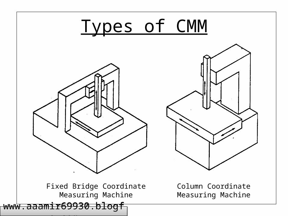
Types of CMM
Fixed Bridge Coordinate Measuring Machine
Column Coordinate Measuring Machine
www.aaamir69930.blogfa.comwww.aaamir69930.blogfa.com

Types of CMM
Moving Ram Horizontal Arm Coordinate Measuring Machine
Moving Table Horizontal Arm Coordinate Measuring Machine
www.aaamir69930.blogfa.comwww.aaamir69930.blogfa.com

Types of CMM
Gantry Coordinate Measuring Machine
L-shaped Bridge Coordinate Measuring Machine
www.aaamir69930.blogfa.comwww.aaamir69930.blogfa.com

Types of CMM
Fixed Table Horizontal Arm Coordinate Measuring Machine
Moving Table Cantilever Arm Coordinate Measuring Machine
www.aaamir69930.blogfa.comwww.aaamir69930.blogfa.com

Probe Systems
Switching probe system Continuous measuring probe system Kinematic touch trigger probe
www.aaamir69930.blogfa.comwww.aaamir69930.blogfa.com

Proximity Sensor
sensing array
x
y
A
x = 0.5 y tan(A)
www.aaamir69930.blogfa.comwww.aaamir69930.blogfa.com

Diffracto Non-contact Laser Probe
SURFACE
Measuring Range
Laser Light Source
Digital Solid-state sensor
Lens
30o
www.aaamir69930.blogfa.comwww.aaamir69930.blogfa.com

Automatic Axis Alignment
Xw, Yw, Zw – Work piece related coordinate system
XM, YM, ZM – Machine related coordinate system
www.aaamir69930.blogfa.comwww.aaamir69930.blogfa.com

Measurement with a CMM
• Step 1: Calibration of the stylus or probe tip with respect to the probe head reference point using a calibrated ball.
• Step 2: Metrological determination of the work piece position in the measuring machine-related coordinated system.
• Step 3: Measurement of the surface points on the work piece in the measuring machine-related coordinate system.
• Step 4: Evaluation of the geometric parameters of the work piece
• Step 5: Representation of the measurement results after coordinate transformation into the work piece related coordinate system.
www.aaamir69930.blogfa.comwww.aaamir69930.blogfa.com

Basic Geometric elements
Circle: Requires 3 points for measurement: By measuring 4 (up to 50) or more points form deviation is determined
Plane: Planar measurements require 4 or more points for form. The intersection of Planes 2 and 3 generate Line 5; Point 6 is the intersection of Plane 4 and Line 5
Cylinder: To define a cylinder, 5 points are necessary. Calculations provide its axis and diameter. The intersection of the Cylinder 7 and Plane 4 is Line 8.
Cone: The cone (or taper) requires at least 6 points for definition. Calculations determine the cone’s included angle and its axis in space.
Sphere: The location of a sphere is found by measuring 4 points is also calculated.
www.aaamir69930.blogfa.comwww.aaamir69930.blogfa.com

Calculated Solution - Distance
www.aaamir69930.blogfa.comwww.aaamir69930.blogfa.com

Calculated Solution - Distance
www.aaamir69930.blogfa.comwww.aaamir69930.blogfa.com

Calculated Solutions - Angle
www.aaamir69930.blogfa.comwww.aaamir69930.blogfa.com

Calculated Solutions - Plane
www.aaamir69930.blogfa.comwww.aaamir69930.blogfa.com

Calculated Solutions - Circle
www.aaamir69930.blogfa.comwww.aaamir69930.blogfa.com

Calculated Solutions - Cylinder
www.aaamir69930.blogfa.comwww.aaamir69930.blogfa.com

Calculated Solutions - Sphere
www.aaamir69930.blogfa.comwww.aaamir69930.blogfa.com

Calculated Solutions - Cone
www.aaamir69930.blogfa.comwww.aaamir69930.blogfa.com

Data flow between CAD/CAM system and CMM
C AD
C AM
N Cprocessor
C M Mprocessor
C M MN C
m achinecenter
Part C M M Inspection
U pdate N Cpart program
Flag tool roomTool
m anagem entand planning
Theoritica l part
P art P rogram
for m inor too ling wearand m ach inead justm ent
for m ajor flaws
www.aaamir69930.blogfa.comwww.aaamir69930.blogfa.com

Volume/Variety Options for Inspection Equipment
www.aaamir69930.blogfa.comwww.aaamir69930.blogfa.com

Schematic Diagram of an FIS
www.aaamir69930.blogfa.comwww.aaamir69930.blogfa.com

Distribution of points on a lobed circle
www.aaamir69930.blogfa.comwww.aaamir69930.blogfa.com

Example of insufficient sampling
Insufficient sampling of a high-frequency component results in a low-frequency alias
www.aaamir69930.blogfa.comwww.aaamir69930.blogfa.com
www.aaamir69930.blogfa.comwww.aaamir69930.blogfa.com

www.aaamir69930.blogfa.comwww.aaamir69930.blogfa.com

www.aaamir69930.blogfa.comwww.aaamir69930.blogfa.com

Minimum form error that could be detected by certain number of points on certain lobes
www.aaamir69930.blogfa.comwww.aaamir69930.blogfa.com
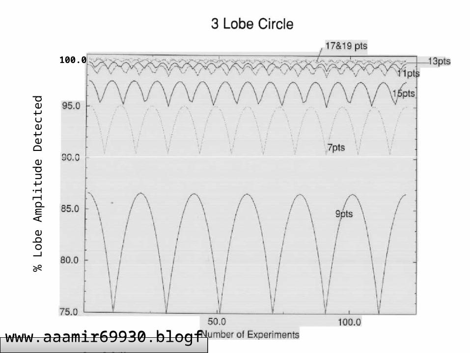
% L
obe
Am
plitu
de D
etec
ted
100.0
www.aaamir69930.blogfa.comwww.aaamir69930.blogfa.com