batteries by ethan craig self dissertation submitted...
TRANSCRIPT

1
ELECTROSPUN PARTICLE/POLYMER FIBER MAT ELECTRODES FOR LI-ION
BATTERIES
By
Ethan Craig Self
Dissertation
Submitted to the Faculty of the
Graduate School of Vanderbilt University
in partial fulfillment of the requirements
for the degree of
DOCTOR OF PHILOSOPHY
in
Chemical Engineering
May, 2017
Nashville, Tennessee
Approved:
Peter N. Pintauro, Ph.D., Chair
Paul E. Laibinis, Ph.D.
Cary L. Pint, Ph.D.
Bridget R. Rogers, Ph.D.

Copyright © 2017 by Ethan Craig Self
All Rights Reserved

iii
Dedicated to my lifelong childhood friend, Mitchell James Webb. May you rest in peace.

iv
ACKNOWLEDGEMENTS
I thank everyone who made contributions which were essential to the completion
of this dissertation. My most sincere gratitude goes to my thesis advisor, Professor
Peter N. Pintauro, for accepting me into his research group and supporting my studies at
Vanderbilt. Without his guidance, none of this work would have been possible. I thank
Professors Paul E. Laibinis, Cary L. Pint, Bridget R. Rogers, and M. Douglas LeVan for
providing valuable feedback on my research while serving on my thesis committee.
I also want to acknowledge all members of the Pintauro group for their support
while I navigated my Ph.D. Professor Ryszard Wycisk and his expertise in polymer
chemistry were vital resources in the laboratory, and his affable personality ensured the
countless hours spent in Olin Hall were both productive and enjoyable. I also want to
specially acknowledge Dr. Jason Ballengee for his mentorship during my early years at
Vanderbilt and for being a model graduate student whom I strived to emulate throughout
my studies. Daniel Anastos, Megan Burcham, and Emily McRen were undergraduate
researchers who worked on various aspects of this project. Emily made substantial
contributions to the studies on carbon anodes, Si anodes, and LiCoO2 cathodes.
Several collaborators made significant contributions to this work. Professor
Yang-Tse Cheng and his graduate student Jiagang Xu at the University of Kentucky
taught me how to construct and characterize coin cells. Professor Rizia Bardhan and her
graduate student William R. Erwin at Vanderbilt assisted with Raman analysis of LiCoO2
nanoparticles. Drs. Jagjit Nanda, Michael Naguib, and Rose Ruther at Oak Ridge
National Laboratory (ORNL) performed post-mortem analysis of electrospun Si-based
anodes. Dr. Gao Liu at Lawrence Berkeley National Laboratory (LBNL) contributed to a

v
collaboration among Vanderbilt, ORNL, and LBNL by providing Si nanoparticles and
electronically conductive polymer binder. Professor Sreeram Vaddiraju at Texas A&M
University provided Si nanowires for anode fabrication.
I also want to thank several members of the Vanderbilt community for their
diligent work which was vital for completion of my research. Mary Gilleran, Rae Uson,
Julie James, Julie Canada, and Angie Pernell provided friendly administrative assistance
and were always prompt in processing my purchase requests and travel forms. Mark
Holmes helped install several pieces of laboratory equipment. Professors Anthony Hmelo
and James McBride worked tirelessly to ensure laboratory facilities were available to the
VINSE research community.
Fellow graduate students and members of the Nashville community made my
time spent at Vanderbilt unforgettable. The past five years have been filled with some of
the happiest moments of my life, and I am fortunate to have shared these experiences
with so many compassionate individuals. Thanks to you all for your friendship and
kindness.
Most importantly, I want to thank my family for their unwavering love and
support. My parents and sister helped me put life in perspective throughout the highs and
lows of graduate school. My nephews Kip and Ray Keyser constantly reminded me that
there is beauty in life despite the myriad of problems that humanity faces.
This work was funded by the National Science Foundation (NSF EPS-1004083)
through the TN-SCORE program under Thrust 2 and the United States Department of
Energy (DE-EE0007215).

vi
TABLE OF CONTENTS
Page
DEDICATION ................................................................................................................... iii
ACKNOWLEDGEMENTS ............................................................................................... iv
LIST OF TABLES ........................................................................................................... viii
LIST OF FIGURES ........................................................................................................... ix
Chapter
I. INTRODUCTION ............................................................................................................1
References ................................................................................................................6
II. BACKGROUND .............................................................................................................7
2.1 Principles of Li-ion Batteries .............................................................................7
2.2 Characterization of Li-ion Batteries ...................................................................9
2.3 Prior Research on Li-ion Battery Electrodes ...................................................15
2.3.1 Anode Materials and Designs ...........................................................15
2.3.2 Cathode Materials and Designs ........................................................21
2.4 Electrospinning Background ............................................................................25
2.5 Prior Research on Electrospun Fiber Mats as Li-ion Battery Electrodes ........26
2.6 Project Objectives ............................................................................................30
2.7 References ........................................................................................................32
III. ELECTROSPUN TITANIA-BASED FIBERS FOR HIGH AREAL CAPACITY
LI-ION BATTERY ANODES ...........................................................................................37
3.1 Introduction ......................................................................................................37
3.2 Experimental ....................................................................................................42
3.3 Results and Discussion ....................................................................................44
3.4 Conclusions ......................................................................................................55
3.5 References ........................................................................................................57
vii
IV. HIGH PERFORMANCE C/PVDF NANOFIBER ANODES FOR LI-ION
BATTERIES USING PARTICLE/POLYMER ELECTROSPINNING ...........................59
4.1 Introduction ......................................................................................................59
4.2 Experimental ....................................................................................................63
4.3 Results and Discussion ....................................................................................66
4.4 Conclusions ......................................................................................................82
4.5 References ........................................................................................................84
V. LICOO2-BASED FIBER CATHODES FOR ELECTROSPUN FULL CELL
LI-ION BATTERIES .........................................................................................................86
5.1 Introduction ......................................................................................................86
5.2 Experimental ....................................................................................................89
5.3 Results and Discussion ....................................................................................92
5.4 Conclusions ....................................................................................................110
5.5 References ......................................................................................................112
VI. ELECTROSPUN PARTICLE/POLYMER SI-BASED NANOFIBER ANODES
FOR LI-ION BATTERIES ..............................................................................................114
6.1 Introduction ....................................................................................................114
6.2 Experimental ..................................................................................................117
6.3 Results and Discussion ..................................................................................121
6.3.1 Anodes with Poly(acrylic acid) (PAA) Binder ...............................121
6.3.2 Anodes with Electronically Conductive Polymer Binders .............139
6.4 Conclusions ....................................................................................................149
6.5 References ......................................................................................................153
VII. SUMMARY .............................................................................................................156
VIII. CONCLUSIONS .....................................................................................................163
IX. SUGGESTIONS FOR FUTURE WORK .................................................................165
Appendix
A. SYNTHESIS OF LICOO2 NANOPARTICLES.........................................................171
A.1 Experimental Methods and Results...............................................................171
A.2 References .....................................................................................................173
B. RATE CAPABILITIES OF TIO2/C/PAA, C/PVDF, and LICOO2/C/PVDF FIBER
MAT ELECTRODES ......................................................................................................174
C. ELECTROSPUN FIBER MAT ANODES PREPARED WITH SI NANOWIRES ...176
viii
LIST OF TABLES
Table Page
2.1. Description of several active materials for cathodes which store Li through an
intercalation reaction.[1, 70]................................................................................................. 22
2.2. Summary of previously reported electrospun carbon nanofiber mat anodes and
cathodes for LIBs. ............................................................................................................. 29
3.1. Volumetric capacity of electrospun and slurry cast titania-based anodes. ................ 55
5.1. Areal and volumetric capacities of full cells containing LiCoO2/C/PVDF
cathodes and C/PVDF anodes. ........................................................................................ 109
6.1. Electrospinning conditions for PFM and PFM/PEO solutions. All solutions
contained 5 wt % polymer in a mixture of chlorobenzene/chloroform
(1/1 by weight). ............................................................................................................... 140
6.2. Electrospinning conditions for inks containing Si/PFM/PEO containing
35 and 50 wt % Si. .......................................................................................................... 142

ix
LIST OF FIGURES
Figure Page
1.1. A Ragone plot showing the energy and power density of rechargeable batteries
and supercapacitors. Image reproduced from Hayner et al.[8] with permission from
Annual Reviews. ................................................................................................................. 2
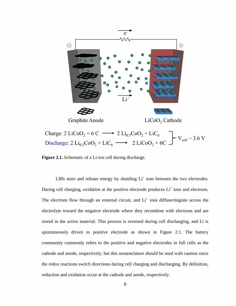
2.1. Schematic of a Li-ion cell during discharge. ............................................................... 8
2.2. Charge/discharge curves for a commercial graphite anode collected over 3 cycles
at 0.1 C. Image adapted from Towada et al.[5] with permission from Elsevier. ............... 11
2.3. Specific capacity and operating potentials for (a) intercalation-type cathodes,
(b) conversion-type cathodes, (c) conversion-type anodes, and (d) an overview of
various anodes and cathodes. Image reproduced from Nitta et al.[1] with permission
from Elsevier. .................................................................................................................... 12
2.4. Si anode failure mechanisms: (a) material pulverization, (b) morphology and
volume change of the entire Si electrode, and (c) continuous SEI growth. Image
inspired by Wu and Cui.[37] ............................................................................................... 19
2.5. Schematic of a typical electrospinning setup. Image reproduced from
Cavaliere et al.[94] with permission from The Royal Society of Chemistry. ..................... 26
2.6. CNF mat prepared from a PAN/poly(pyrrole) (PPy) blend where the PAN/PPy
weight ratio was 85/15. Image adapted from Ji et al.[104] with permission from
Elsevier. ............................................................................................................................ 28
3.1. SEM images of TiO2/C/PAA anodes. (a) An as-spun electrospun mat, (b) a
compacted electrospun man with a 0.54 fiber volume fraction and (c) a conventional
slurry cast anode. .............................................................................................................. 45
3.2. (a) Cyclic voltammograms, (b) charge/discharge curves collected at 0.1 C during
the 1st, 2nd, 10th and 50th cycles, and (c) long-term performance over 510 cycles for
electrospun TiO2/C/PAA anodes. ..................................................................................... 48
3.3. SEM of an electrospun anode fiber electrode after 50 charge/discharge cycles
at 0.5 C. ............................................................................................................................. 49
3.4. Normalized capacity vs. C-rate for different electrospun and slurry cast electrodes.
(a) Low mass loading, and (b) high mass loading. Capacities are normalized with
respect to the capacity at 0.1 C. ........................................................................................ 50
x
3.5. Areal capacity as a function of C-rate for electrospun anodes of different
thicknesses (50 µm = 1.38 mg cm-2, 600 µm = 21.9 mg cm-2, 1.0 mm = 40.2 mg cm-2,
and 1.4 mm = 54.1 mg cm-2). ............................................................................................ 52
3.6. Comparison of areal capacity and rate capabilities of a particle/polymer
electrospun system with several other reports in the literature. ........................................ 54
4.1. Electrospinning apparatus used to produce a particle/polymer nanofiber mat. ......... 67
4.2. SEM image of an as-spun C/PVDF nanofiber anode with a fiber volume fraction
of 0.18. .............................................................................................................................. 67
4.3. The effect of applied compaction pressure on fiber volume fraction and mat
density. Error bars represent the standard deviation of at least three samples. ................ 68
4.4. SEM images of electrospun C/PVDF nanofiber anodes with fiber volume
fractions of (a) 0.39 and (b) 0.80 and (c) a slurry cast C/PVDF anode. ........................... 69
4.5. Electrochemical characterization of C/PVDF nanofiber anodes. (a) Cyclic
voltammograms collected at a scan rate of 0.5 mV s-1 and (b) Nyquist plot showing
experimental data and the fit for an equivalent circuit model.[26] ..................................... 72
4.6. Electrochemical characterization of C/PVDF nanofiber anodes.
(a) Charge/discharge curves at current densities corresponding to 0.1 – 5 C,
(b) cycling stability at 0.1 – 5 C, and (c) long-term performance over 510 cycles
at 0.1 C. ............................................................................................................................. 73
4.7. SEM images of a C/PVDF nanofiber anode containing a fiber volume fraction of
0.25 (a) before cycling and (b) after 510 cycles at 0.1 C. ................................................. 74
4.8. (a) Volumetric capacity at 0.1 C as a function of fiber volume fraction in the
anode, (b) volumetric capacity at charge/discharge rates up to 5 C for electrospun and
slurry cast anodes, (c) cycling stability at 2 C for a C/PVDF nanofiber anode, and
(d) Areal capacity at charge/discharge rates (C-rate) up to 5 C for nanofiber and slurry
cast anodes. φfiber refers to fiber volume fraction in (b) – (d). .......................................... 76
4.9. Rate capabilities of a nanofiber anode (fiber volume fraction = 0.34) compared to
slurry cast anodes containing either Vulcan XC-72R or high surface area activated
carbon as the active material. All anodes contained 65 wt % carbon nanoparticles
and 35 wt % PVDF binder. ............................................................................................... 78

xi
4.10. (a) Areal capacity at 0.1 C as a function of anode thickness for electrospun
anodes containing fiber volume fractions of 0.59 – 0.66, (b) rate capabilities of
electrospun anodes containing fiber volume fractions of 0.59 – 0.66 and thicknesses
up to 510 µm, and (c) rate capabilities of thick electrospun anodes containing fiber
volume fractions (φfiber) of 0.42 and 0.63 and thicknesses of 820 and 510 µm,
respectively. ...................................................................................................................... 81
5.1. TEM images of (a) as-received Co3O4 nanoparticles and (b) synthesized LiCoO2
nanoparticles. .................................................................................................................... 93
5.2. (a) XRD patterns for the as-received Co3O4 and synthesized LiCoO2
nanoparticles, (b) Rietveld refinement of the XRD pattern for the LiCoO2
nanoparticles, and (c) Raman spectra for Co3O4 and LiCoO2 nanoparticles. ................... 95
5.3. SEM images of LiCoO2/C/PVDF cathodes. (a) An as-spun fiber mat with a fiber
volume fraction of 0.25, compacted fiber mats with fiber volume fractions of (b) 0.65
and (c) 0.85, and (d) a slurry cast cathode. All electrodes contained LiCoO2/C/PVDF
in a 70/10/20 weight ratio. ................................................................................................ 97
5.4. Fundamental electrochemical characterization of an electrospun LiCoO2/C/PVDF
fiber cathode. (a) Cyclic voltammogram, (b) charge/discharge curves collected
at 0.1 – 2 C, (c) cycling stability at 0.1 – 2 C, and (d) long-term cycling stability
at 0.1 – 0.5 C. .................................................................................................................... 99
5.5. SEM images of a LiCoO2/C/PVDF fiber mat cathode (a) before cycling and
(b) after 100 cycles at 0.1 C. ........................................................................................... 100
5.6. SEM images of electrospun LiCoO2/C/PVDF fiber mat anodes where the
LiCoO2/C/PVDF weight ratio is (a) 40/25/35 and (b) 70/10/20. .................................... 101
5.7. Electrochemical performance of LiCoO2/C/PVDF fiber mat cathodes in half
cells where the LiCoO2/C/PVDF weight ratio 40/25/35 and 70/10/20.
(a) Charge/discharge curves at 0.1 C, (b) Cycling stability over 10 cycles at 0.1 C,
and (c) Gravimetric capacity at 0.1 – 2 C. ..................................................................... 103
5.8. Rate capabilities of electrospun and slurry cast LiCoO2/C/PVDF cathodes.
(a) Gravimetric (b) areal, and (c) volumetric capacities at 0.1 – 2 C. All electrodes
contained LiCoO2/C/PVDF in a 70/10/20 weight ratio. ................................................. 105
5.9. Electrochemical characterization of full cells containing a LiCoO2/C/PVDF
cathode and C/PVDF anode. (a) Charge/discharge curves at 0.1 – 2 C for a full cell
with an electrospun cathode/anode and (b) cycling stability at 0.1 – 2 C for full cells
containing either electrospun electrodes or slurry cast electrodes. ................................. 108

xii
6.1. Top-down SEM images of electrospun nanofiber mats containing Si/C/PAA in
a 40/25/35 weight ratio. (a,b) an as-spun fiber mat and (c,d) a compacted/welded
fiber mat. ......................................................................................................................... 123
6.2. (a) Low and (b) high magnification cross-sectional SEM images of a
compacted/welded fiber mat containing Si/C/PAA in a 40/25/35 weight ratio.............. 123
6.3. Electrochemical characterization of electrospun anodes containing Si/C/PAA in
a 40/25/35 weight ratio. (a) Charge/discharge curves for the 1st and 2nd cycles (solid
and dashed lines, respectively) for as-spun and compacted/welded fiber mats and
(b) gravimetric capacity over 50 cycles at 0.1 C for as-spun, compacted (unwelded),
welded (uncompacted), and compacted/welded fiber mats. ........................................... 126
6.4. (a) Gravimetric capacity and (b) areal capacity of compacted/welded Si/C/PAA
nanofiber mats over 50 cycles at 0.1 C. Electrodes at two different loadings (0.71
and 3.49 mg cm-2) were characterized. The electrodes contained Si/C/PAA in a
40/25/35 weight ratio. ..................................................................................................... 129
6.5. Raman spectra of Si/C/PAA fiber mat anodes before and after 50 cycles at 0.1 C.
The electrodes contained Si/C/PAA in a 40/25/35 weight ratio. .................................... 131
6.6. Raman maps collected over an area ~ 4.5 x 9 µm2 showing the Raman shift of
the maximum peak for Si/C/PAA fiber mat anodes (a) before cycling and (b) after 50
cycles at 0.1 C. The electrodes contained Si/C/PAA in a 40/25/35 weight ratio. .......... 132
6.7. Cross-sectional SEM images of a Si/C/PAA nanofiber mat anode (a,c,e) before
cycling and (b,d,f) after 50 cycles at 0.1 C. The electrodes contained Si/C/PAA in a
40/25/35 weight ratio. ..................................................................................................... 134
6.8. SEM image of a compacted/welded nanofiber mat with a fiber volume fraction
of 0.85 and Si/C/PAA in a 15/50/35 weight ratio. .......................................................... 136
6.9. Electrochemical characterization of compacted/welded nanofiber mat anodes
containing Si/C/PAA weight ratios of 40/25/35 and 15/50/35. (a) Gravimetric
capacity and (b) capacity retention over 50 cycles at 0.1 C. ........................................... 136
6.10. Electrochemical characterization of a full cell containing an electrospun
Si/C/PAA anode and LiCoO2/C/PVDF cathode. (a) Charge/discharge curve collected
at 0.1 C and (b) cycling stability over 10 cycles at 0.1 C. The anode contained
Si/C/PAA in a 40/25/35 weight ratio, and the cathode contained LiCoO2/C/PVDF
in a 70/10/20 weight ratio. .............................................................................................. 138
6.11. Structure of the electronically conductive polymer binders, PFM and PEFM.
Image adapted from Wu et al.[52] with permission from The American Chemical
Society............................................................................................................................. 139

xiii
6.12. SEM images of electrospun (a,b) neat PFM fibers and (c – f) PFM/PEO fibers
prepared at (c,d) 15 % rh and (e,f) 75 % rh. The PEO carrier polymer content in
(b – f) was 1 wt %. .......................................................................................................... 141
6.13. SEM images of electrospun Si/PFM/PEO fiber mats containing: (a,b) 35 wt %
Si and (c,d) 50 wt % Si. All samples contained 1 wt % PEO as a carrier polymer, and
electrospinning was conducted at 75 % rh. ..................................................................... 143
6.14. SEM images of fiber mats containing a Si/PFM/PEO weight ratio of 50/49/1
which were electrospun at (a) 15 % rh and (b) 75 % rh. ................................................ 143
6.15. Typical charge/discharge curves collected at 0.1 C for electrospun and slurry
cast anodes containing Si/PFM/PEO in a 50/49/1 weight ratio. Electrospun fiber
mats were prepared at 15 % rh and 75 % rh. .................................................................. 145
6.16. (a,b) Charge/discharge curves collected at 0.01 C for slurry cast Si/PFM anodes
containing (a) 50 – 67 wt % Si and (b) 50 – 60 wt % Si. (c) Cycling stability of a
Si/PFM anode with 67 wt % Si at 0.01 C for 1 cycle and 0.1 C for 50 cycles. .............. 147
6.17. (a) Charge/discharge curves collected at 0.01 C for slurry cast Si/PEFM anodes
containing 55 and 60 wt % Si. (b) Cycling stability of a Si/PEFM anode with
60 wt % Si over 1 cycle at 0.01 C and 50 cycles at 0.1 C. ............................................. 149
A.1. SEM images of LiCoO2 nanoparticles synthesized using a (a,b) sol-gel method
and (c,d) the sonochemical method described in Chapter V. ......................................... 172
B.1. (a) Areal capacity and (b) capacity retention of electrospun fiber mat
TiO2/C/PAA, C/PVDF, and LiCoO2/C/PVDF electrodes at 0.1 – 2 C in half cells.
Capacity retention in (b) is calculated by normalizing the capacity with respect to
the capacity measured at 0.1 C for each electrode. The electrodes contained
TiO2/C/PAA, C/PVDF, and LiCoO2/C/PVDF in a 40/25/35, 65/35, and 70/10/20
weight ratio, respectively. ............................................................................................... 175
C.1. SEM images of (a,b) Si nanowires and (c,d) electrospun nanofibers containing
Si nanowires, carbon black, and PAA in a 40/25/35 weight ratio. ................................. 177
C.2. Electrochemical performance of as-spun Si/C/PAA nanofiber mats where the
Si active material is either in the form of nanowires or nanoparticles. (a) Gravimetric
capacity and (b) capacity retention over 50 cycles at 0.1 C. ........................................... 178

1
CHAPTER I
INTRODUCTION
Since the Industrial Revolution, human innovation has driven the development of
new technologies that form the cornerstones of modern-day life. While this progress has
vastly improved the average quality of life worldwide, humanity now faces an energy
crisis caused by population growth and depletion of finite natural resources. The global
energy demand is expected to double by 2050, so developing clean energy technologies is
of utmost importance to ensure a sustainable future.[1-3] Many renewable energy
resources—such as sunlight, wind, and tides—are intermittent by nature, and thus energy
storage systems are required to store and release this energy as needed.
Secondary (i.e., rechargeable) batteries have several attractive features as energy
storage devices including: (i) emissionless operation, (ii) high round-trip efficiency,
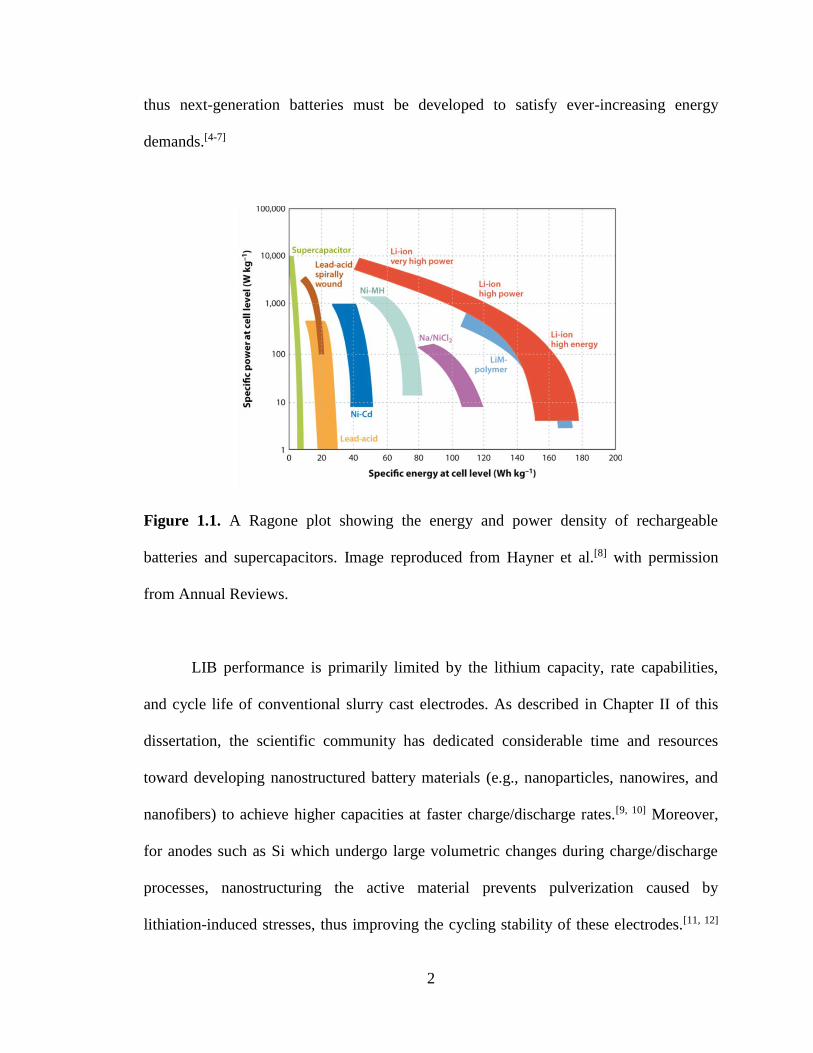
(iii) low maintenance, and (iv) flexible energy and power characteristics.[1] The Ragone
plot in Figure 1.1 shows that Li-ion batteries (LIBs) have the highest specific energy and
power of any commercially available secondary battery technology. Furthermore, a low
self-discharge rate and the lack of a memory effect make LIBs user-friendly for consumer
devices.[4, 5] Since their commercial debut in 1991, LIBs have revolutionized the
functionality of portable electronics, and the LIB industry continues to grow today due
emerging applications such as electric vehicle propulsion. Despite the extraordinary
commercial success of LIBs, many devices are still limited by battery performance, and
2
thus next-generation batteries must be developed to satisfy ever-increasing energy
demands.[4-7]
Figure 1.1. A Ragone plot showing the energy and power density of rechargeable
batteries and supercapacitors. Image reproduced from Hayner et al.[8] with permission
from Annual Reviews.
LIB performance is primarily limited by the lithium capacity, rate capabilities,
and cycle life of conventional slurry cast electrodes. As described in Chapter II of this
dissertation, the scientific community has dedicated considerable time and resources
toward developing nanostructured battery materials (e.g., nanoparticles, nanowires, and
nanofibers) to achieve higher capacities at faster charge/discharge rates.[9, 10] Moreover,
for anodes such as Si which undergo large volumetric changes during charge/discharge
processes, nanostructuring the active material prevents pulverization caused by
lithiation-induced stresses, thus improving the cycling stability of these electrodes.[11, 12]

3
Despite their promising performance, such nanostructured electrodes remain distant from
commercial applications due to their expensive fabrication methods and low areal and
volumetric capacities.
To address the shortcomings of previously reported nanoscale battery electrodes,
this dissertation details the fabrication and characterization of fiber mat LIB electrodes
prepared using particle/polymer electrospinning, a technique originally developed by
Pintauro and coworkers for fuel cell electrodes.[13-16] Electrospun fiber mat LIB
electrodes typically contain three components—active material nanoparticles for Li
storage, carbon powder for electrical conduction (only required when the other electrode
components have low electronic conductivity), and a polymer binder. These
particle/polymer fiber mats offer several advantages over conventional slurry cast
electrodes, including: (i) a large electrode/electrolyte interfacial area, (ii) short Li+
transport pathways between the electrolyte and active material in the radial fiber
direction, and (iii) good electrolyte infiltration throughout the intra- and interfiber void
space of the fiber mat. Furthermore, the presence of the polymer binder ensures the mats
can be compacted under high pressure without fracturing, so thick, densely packed fiber
mats can be used to achieve high gravimetric, areal, and volumetric capacities. For
practical battery applications, high areal capacities are desired to reduce the amount of
inactive cell components (e.g., current collectors, separators, etc.), and batteries with a
high volumetric capacity allow more energy to be stored within a given space.[17]
Particle/polymer electrospinning is compatible with various active materials and
binders, enabling the development of a wide range of fiber electrodes. Chapters III – VI
of this dissertation detail the preparation and characterization of four types of
4
particle/polymer fiber mat LIB electrodes. Each chapter makes substantial contributions
to the literature, and when considered as a whole, this dissertation demonstrates that
particle/polymer electrospinning is an attractive technique for fabricating high
performance electrodes for electrochemical energy storage devices.
Chapter III describes the first ever use of particle/polymer electrospinning for LIB
applications. Fiber mat anodes containing titania nanoparticles and carbon powder
distributed throughout a poly(acrylic acid) binder (TiO2/C/PAA) were prepared and
characterized. The electrochemical properties of electrospun and slurry cast TiO2/C/PAA
anodes were evaluated in half cells containing a Li metal counter/reference electrode. The
performance of TiO2/C/PAA fiber mats with thicknesses up to 1.4 mm was evaluated
over a range of charge/discharge rates and compared to that of published data for anodes
containing either titania, carbon, or silicon active materials.
Electrodes containing electronically conductive carbon active materials (active
materials reversibly store Li during charge/discharge processes) do not require
conductive additives and thus can be used to prepare electrospun mats with high active
material loadings in the fiber. The use of carbon nanofiber anodes containing carbon
powder and poly(vinylidene fluoride) (PVDF) binder is described in Chapter IV. The
areal and volumetric capacities of electrospun C/PVDF mats with a range of thicknesses
and fiber volume fractions were determined in half cells. The rate capabilities of C/PVDF
nanofiber electrodes were compared to those of conventional slurry cast anodes.
Although most studies in the literature only discuss electrode performance in a
half cell configuration, both anode and cathode materials are required for practical full
cell devices. Chapter V details the preparation and characterization of electrospun LIB
5
cathodes containing LiCoO2 nanoparticles, carbon powder, and PVDF
(LiCoO2/C/PVDF). The LiCoO2/C/PVDF fiber mat cathodes were characterized in half
cells and in full cells containing an electrospun C/PVDF anode (described in Chapter IV).
The full cell results represent the first ever LIB prepared using a paired electrospun
particle/polymer fiber mat cathode and anode. The performance of the electrospun
electrodes was compared to that of conventional slurry cast electrodes of the same
composition at slow and fast charge/discharge rates.
Si has been widely investigated as a replacement for graphite used in today’s LIB
anodes due to its high capacity and low operating potential, but Si-based anodes typically
have poor cycling stability due to the large volumetric changes of Si during battery
charge/discharge operation. Chapter VI describes electrospun Si-based anodes containing
Si nanoparticles, carbon powder, and PAA (Si/C/PAA). Qualitative
performance/composition/structure correlations were established by evaluating the
performance of Si/C/PAA fiber mats with different compositions, fiber volume fractions,
interfiber connectivities, thicknesses, and loadings in half cells. A full cell containing an
electrospun Si/C/PAA anode and electrospun LiCoO2/C/PVDF cathode (described in
Chapter V) was also characterized. In addition to these studies on Si/C/PAA anodes,
Chapter VI also describes electrospun and slurry cast anodes prepared with Si
nanoparticles and one of two electronically conductive polymer binders (PFM and
PEFM) where the electrodes contained 20 – 67 wt % Si.

6
References
[1] B. Dunn, H. Kamath, J.-M. Tarascon, Science 2011, 334, 928.
[2] A. Thatcher, P. H. Yeow, Appl Ergon 2016, 57, 1.
[3] N. S. Lewis, D. G. Nocera, Proc. Natl. Acad. Sci. USA 2006, 103, 15729.
[4] J.-M. Tarascon, M. Armand, Nature 2001, 414, 359.
[5] M. Armand, J.-M. Tarascon, Nature 2008, 451, 652.
[6] J. B. Goodenough, Y. Kim, Chem. Mater. 2010, 22, 587.
[7] J. B. Goodenough, Acc. Chem. Res. 2013, 46, 1053.
[8] C. M. Hayner, X. Zhao, H. H. Kung, Annu. Rev. Chem. Biomol. Eng. 2012, 3,
445.
[9] C. Liu, F. Li, L. P. Ma, H. M. Cheng, Adv. Mater. 2010, 22, E28.
[10] L. Ji, Z. Lin, M. Alcoutlabi, X. Zhang, Energy Environ. Sci. 2011, 4, 2682.
[11] H. Wu, Y. Cui, Nano Today 2012, 7, 414.
[12] U. Kasavajjula, C. Wang, A. J. Appleby, J. Power Sources 2007, 163, 1003.
[13] W. Zhang, P. N. Pintauro, ChemSusChem 2011, 4, 1753.
[14] M. Brodt, R. Wycisk, P. N. Pintauro, J. Electrochem. Soc. 2013, 160, F744.
[15] M. Brodt, T. Han, N. Dale, E. Niangar, R. Wycisk, P. Pintauro, J. Electrochem.
Soc. 2014, 162, F84.
[16] M. Brodt, R. Wycisk, N. Dale, P. Pintauro, J. Electrochem. Soc. 2016, 163, F401.
[17] N. Nitta, G. Yushin, Part. Part. Syst. Char. 2014, 31, 317.

7
CHAPTER II
BACKGROUND
2.1 Principles of Li-ion Batteries
Li-ion batteries (LIBs) are electrochemical energy storage devices that convert
chemical energy to electrical energy through redox reactions involving reversible Li
storage in the electrodes. A LIB is constructed from two or more cells connected in series
and/or parallel arrangements, and each cell is comprised of three components— a
negative electrode, a positive electrode, and an ionically conductive electrolyte. The
electrodes typically contain a mixture of active material that stores Li, electronically
conductive carbon, and a polymer binder. Figure 2.1 shows a schematic of a LIB with
graphite and LiMO2 (where M = Co, Mn, or Ni) as the negative and positive electrodes,
respectively. These electrode materials have a layered structure where the inter-plane
spacing is sufficiently large to intercalate Li; similarly, other active materials (e.g., silicon
and sulfur) store Li via conversion reactions which are accompanied by the formation and
breakage of chemical bonds.[1] The electrolyte is ionically conductive to allow transport
of Li+ ions between the electrodes and electronically insulating to prevent short-circuiting
of the cell. The electrolyte can either be a solid, liquid, or gel, but most commercial cells
are prepared with a porous polyolefin separator soaked in a liquid electrolyte containing a
Li-based salt (e.g., LiPF6) dissolved in a mixture of organic carbonates (e.g., ethylene
carbonate and diethyl carbonate).
8
Figure 2.1. Schematic of a Li-ion cell during discharge.
LIBs store and release energy by shuttling Li+ ions between the two electrodes.
During cell charging, oxidation at the positive electrode produces Li+ ions and electrons.
The electrons flow through an external circuit, and Li+ ions diffuse/migrate across the
electrolyte toward the negative electrode where they recombine with electrons and are
stored in the active material. This process is reversed during cell discharging, and Li is
spontaneously driven to positive electrode as shown in Figure 2.1. The battery
community commonly refers to the positive and negative electrodes in full cells as the
cathode and anode, respectively, but this nomenclature should be used with caution since
the redox reactions switch directions during cell charging and discharging. By definition,
reduction and oxidation occur at the cathode and anode, respectively.
9
2.2 Characterization of Li-ion Batteries
LIBs are characterized by the amount of energy stored/delivered during
charge/discharge cycling. The specific energy of a cell Ecell (Wh kg-1) is related to its
lithium capacity Q (Ah) and operating potential Vcell (V) by equation 2.1,
Ecell(Q) = 1
m∫ Vcell(Q')dQ'
Q
0 (2.1)
where m is the mass of the cell. Similarly, the energy density of a cell (Wh L-1) is
normalized with respect to cell volume. Battery researchers typically characterize
individual electrodes (either anodes or cathodes) in half cells where the working electrode
is paired with a Li metal counter/reference electrode which contains a large excess of Li.
This half cell configuration is a convenient and reliable setup which avoids constructing
full cells where capacity matching of the anode and cathode can affect performance.[2]
Half cells are characterized using charge/discharge experiments in which cells are cycled
between upper and lower potential limits— which depend on the chemistry of the
working electrode—by changing the direction of current flow between charging and
discharging steps. These tests most commonly use galvanostatic (i.e., constant current)
protocols.[3]
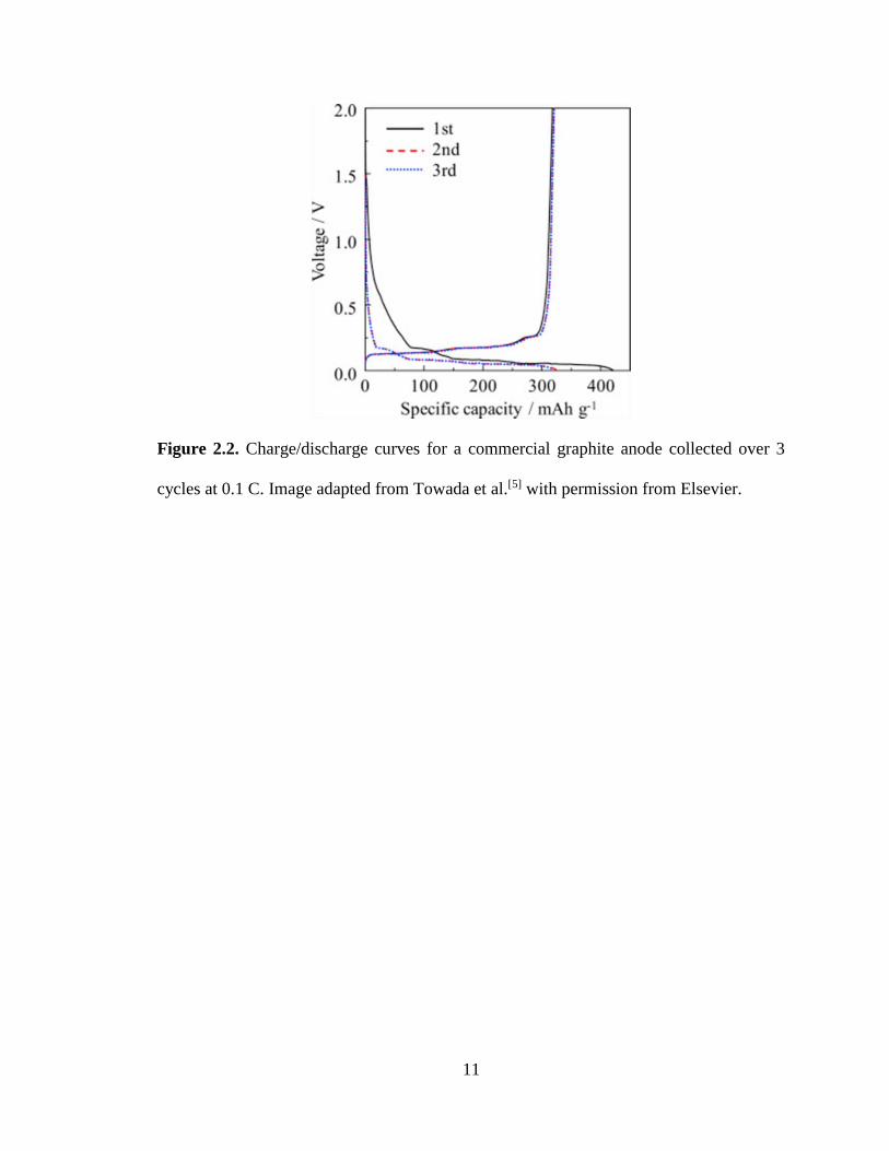
Charge/discharge curves which show cell potential as a function of lithium
capacity give insight to the electrochemical processes occurring in a cell. Figure 2.2
shows charge/discharge collected over 3 cycles for a half cell containing a commercial
graphite working electrode (from hereon referred to as the anode). The cell potential
decreases/increases as graphite is lithiated/delithiated, respectively. The sloping profile at
0.25 – 1 V vs. Li/Li+ during the first lithiation half cycle indicates formation of a solid
electrolyte interphase (SEI) layer on the anode surface. The SEI layer, which is

10
comprised of various electrolyte decomposition products (e.g., lithium alkyl carbonates,
Li2CO3, and LiF), forms when the working electrode’s operating potential is outside the
electrolyte’s electrochemical stability window (approximately 1.3 – 4.5 V vs. Li/Li+ for
standard liquid electrolytes).[4] Desired SEI layer properties include: (i) good adhesion to
the electrode surface, (ii) high Li+ conductivity, (iii) low electronic conductivity, and (iv)
low electrolyte permeability. During subsequent cycles, additional electrolyte
decomposition is hindered by the SEI’s low electronic conductivity and low electrolyte
permeability. The voltage plateaus below 0.5 V vs. Li/Li+ in Figure 2.2 correspond to
lithiation/delithiation of graphite during half cell operation, and the end of the delithiation
(charging) step indicates the graphite electrode has a reversible capacity of
~ 325 mAh g-1. In general, charge/discharge experiments are used to characterize a wide
range of LIB anodes and cathodes where the operating potential and lithium capacity
depend on the chemistry of the active material, with several examples given in
Figure 2.3.
11
Figure 2.2. Charge/discharge curves for a commercial graphite anode collected over 3
cycles at 0.1 C. Image adapted from Towada et al.[5] with permission from Elsevier.

12
Figure 2.3. Specific capacity and operating potentials for (a) intercalation-type cathodes,
(b) conversion-type cathodes, (c) conversion-type anodes, and (d) an overview of various
anodes and cathodes. Image reproduced from Nitta et al.[1] with permission from
Elsevier.
An active material’s theoretical capacity is calculated based on the stoichiometry
of the fully lithiated structure. For an active material AM that can be lithiated to form
LixAM, the theoretical capacity Qtheoretical (mAh g-1) is given by equation 2.2,
Qtheoretical
= xF
Mw ×
mAh
3.6 C (2.2)
where F is Faraday’s constant and Mw is the molecular weight of the active material.
Battery electrodes typically contain multiple components including active material,
conductive additive, and polymer binder, and the theoretical capacity Qtheoretical (mAh g-1)

13
of these composite electrodes is calculated using the simple mixing rule shown in
equation 2.3,
Qtheoretical
= ∑ xii Qi (2.3)
where xi and Qi are the weight fraction and theoretical capacity of component i,
respectively. The electrode’s theoretical capacity is used to calculate the current used
during galvanostatic charge/discharge experiments. This current is described using a
charging rate (C-rate) notation where n-1 C is defined as the current needed to complete a
half cycle (i.e., charge or discharge) in n hours. Charge/discharge experiments are often
conducted over a wide range of currents (e.g., C-rates of 0.1 – 5 C) to evaluate an
electrode’s rate capabilities. In general, electrodes have lower reversible capacities at
higher C-rates due to greater activation, ohmic, and Li+ concentration overpotentials
within the cell. Thus a primary goal of battery research is to minimize these
overpotentials to achieve high reversible capacities at both slow and fast charge/discharge
rates.
While an electrode’s theoretical capacity is calculated using equations 2.2 and 2.3,
experimentally measured capacities Qexpt (mAh g-1) are determined by integrating the
current I (mA) as a function of time t (s), as described by equation 2.4,
Qexpt
(t) = (1
m ×
mAh
3,600 mC) ∫ I(t')dt'
t
0 (2.4)
where m is the overall electrode mass (g). During galvanostatic charge/discharge
experiments in which constant current is used, equation 2.4 simplifies to equation 2.5:
Qexpt
(t) = It
m ×
mAh
3,600 mC (2.5)
The chemical reversibility of the Li storage reaction in an electrode is described by the
coulombic efficiency (CE) calculated using equation 2.6,
14
CE = Qdischarge
Qcharge
× 100 % (2.6)
where Qdischarge and Qcharge are the corresponding half cycle capacities. In general, an
electrode’s discharge capacity is less than its charging capacity due to irreversible
capacity losses caused by SEI layer formation, undesired side-reactions, electronic
isolation of active material, etc.
Equations 2.4 and 2.5 describe gravimetric capacity which is normalized with
respect to electrode mass. Although gravimetric capacity is the most common metric
reported in the literature, an electrode’s areal and volumetric capacities (normalized to
electrode footprint and volume, respectively) should also be considered. Electrodes with
high areal capacity reduce the number of inactive cell components (e.g., separators and
current collectors) which contribute to a battery’s overall size and weight. Similarly,
batteries with high volumetric capacity store more energy in a given space.[3]
While individual electrodes are typically characterized in half cells, the Li metal
anodes in these cells cannot be utilized in consumer devices due to safety issues
associated with Li dendrite growth during charge/discharge cycling.[2, 6, 7] Thus, electrode
performance in full cells containing a Li storage anode and cathode must be considered
for practical battery applications. For full cell testing, the anode and cathode capacities
should be well-matched to ensure good active material utilization in each electrode. In
other words, the amount of Li available in the cathode should be similar to that which can
be stored in the anode. The capacity matching of the negative and positive electrodes
(i.e., anode and cathode, respectively) is described by the quantity N/P in equation 2.7,
N
P =
Qanode
Qcathode
× 100 % (2.7)

15
where Qanode and Qcathode are the electrodes’ reversible capacity. The N/P ratio in a full
cell should be close to 1 to ensure good active material utilization in each electrode.
Overall, full cell performance is evaluated using the same charge/discharge protocols
previously described in this section.
2.3 Prior Research on Li-ion Battery Electrodes
Commercial LIB electrodes are prepared by slurry casting a solution containing
active material, conductive carbon, and polymer binder onto an electronically conductive
current collector (e.g., Cu foil for the anode and Al foil for the cathode).[8] While these
slurry cast electrodes are used in all of today’s commercial batteries, new electrode
materials and designs must be developed to satisfy ever-increasing energy demands of
consumers. Sections 2.3 and 2.4 summarize previous work on the fabrication and
characterization of LIB electrodes.
2.3.1 Anode Materials and Designs
Carbon is one of the most versatile elements in the periodic table, and as such,
many carbon allotropes have been investigated as active materials for LIB anodes. In
general, carbon structures can be classified as either soft carbons, hard carbons, or
nanostructured carbons, each of which has unique Li storage properties.[9, 10] Graphite is
prepared from soft carbons by heating them at high temperature (> 1,000 °C) to align the
graphene layers in a parallel arrangement. Despite their widespread use in commercial
LIBs, slurry cast graphite anodes are limited by their theoretical capacity of 372 mAh g-1
(corresponding to LiC6) and poor rate capabilities (e.g., 63 mAh g-1 at 2 C).[11] Hard
16
carbons have a disordered structure where the graphene layers are randomly oriented, and
Li can be stored between these layers, at the edges of graphene planes, and on crystallite
surfaces.[9] The reversible capacity of hard carbons typically ranges from
150 – 650 mAh g-1 depending on the exact structure of the material.[12-16] Yang et al.[13]
characterized several hard carbon anodes with gravimetric capacities as high as
504 mAh g-1, but these materials had low initial coulombic efficiencies of 28 – 47 % due
to irreversible Li and electrolyte consumption in the cell. Nanostructured carbons such as
carbon nanotubes and graphene flakes have attractive properties for use in LIB anodes
due to their high surface area to volume ratio, high electronic conductivity, and good
mechanical properties. Reversible capacities of 1,264 and 750 mAh g-1 have been
reported for graphene[17] and carbon nanotubes[18], respectively. The high electronic
conductivity of nanostructured carbons also make them useful as conductive additives in
composite electrodes.[19, 20] Despite the attractive properties of these carbon
nanomaterials, their high cost limits their use in commercial battery applications.
Ti-based anodes where the active material is either TiO2 or Li4Ti5O12 are
attractive alternatives to carbon anodes due to their: (i) low volumetric strain during
lithiation/delithiation (e.g., 0.2 % for Li4Ti5O12 vs. ~ 8 % for graphite) which enables
outstanding cycling stability and (ii) high operating potential (ca. 1.5 – 1.8 V vs. Li/Li+)
which lies within the electrochemical stability of common liquid electrolytes and thus
avoids SEI layer formation.[21-26] These advantages are offset by the materials’ low
theoretical capacities (335 and 175 mAh g-1 for TiO2 and Li4Ti5O12, respectively) and low
ionic and electronic conductivities which limits their rate capabilities. To improve the
performance of Ti-based anodes at fast charge/discharge rates, several groups have

17
reported on the preparation and characterization of nanostructured TiO2[27-32] and
Li4Ti5O12[33-35] anodes with large electrode/electrolyte interfacial areas and short Li+
transport pathways. Liu et al.[34] described a carbon-coated Li4Ti5O12 nanotube array
grown directly on a stainless steel current collector with reversible capacities of
165 mAh g-1 at 1 C and 154 mAh g-1 at 10 C. In another study, Xiong et al.[32] showed
that a TiO2 nanowire anode consisting of mixed anatase and bronze phases had a
gravimetric capacity of 166 mAh g-1 at 0.3 C and retained 46 % of this capacity at 4.8 C.
Despite their moderate gravimetric capacities at high C-rates, these nanowire/nanotube
arrays had very low electrode loadings which resulted in poor areal capacities
(<< 1 mAh cm-2). Thus, new nanoscale Ti-based anodes with areal capacities comparable
to that of commercial electrodes (2.5 – 3.5 mAh cm-2) at fast charge/discharge rates must
be developed.
Active materials which electrochemically alloy with Li (e.g., Si, Ge, and Sn) have
much higher capacities (theoretical values of 3,579, 1,600, and 994 mAh g-1, respectively)
compared to intercalation-based compounds.[1, 36] Si anodes will be the focus here since
they have received the most attention in the literature. Lithiation of Si is accompanied by
an active material volumetric expansion > 300 %. Repeated expansion and contraction of
Si during battery cycling results in capacity fade due to: (i) Si pulverization, (ii) Si
electronic isolation, and (iii) formation of an unstable SEI layer.[37, 38] A schematic of
these phenomena is shown in Figure 2.4. Several groups have demonstrated that when Si
materials are reduced to the nanoscale, the stresses required to induce crack formation
and propagation are significantly increased.[39-42] Consequently, lithiation-induced

18
stresses are insufficient to drive Si fracture for Si nanomaterials with characteristic
lengths below ~ 150 nm (e.g., Si nanowires, nanoparticles, etc.).
Although Si pulverization can be eliminated through the use of nanoscale active
materials, effective electrode designs which prevent Si electronic isolation and unstable
SEI layer formation are yet to be developed. Si volumetric changes disrupt the electrode’s
conductivity network, leading to electronic isolation of individual Si particles (see Figure
2.4b). Furthermore, the SEI layer can crack during cycling, which re-exposes the
electrode surface and leads to more SEI formation during subsequent cycles (see
Figure 2.4c). This unstable SEI growth results in irreversible Li and electrolyte
consumption, Si electronic isolation, and increased Li+ transport path lengths between the
Si particles and electrolyte.[37, 43] To address these issues, researchers have investigated
several nanoscale Si anode designs, including: (i) Si thin films, (ii) Si nanowires, (iii) Si
nanoparticle/polymer composites, and (iv) core/shell structures. A summary of each of
these approaches is given below.

19
Figure 2.4. Si anode failure mechanisms: (a) material pulverization, (b) morphology and
volume change of the entire Si electrode, and (c) continuous SEI growth. Image inspired
by Wu and Cui.[37]
Si thin films are deposited onto a current collector using chemical or physical
vapor deposition. High gravimetric capacities up to 3,500 mAh g-1 (equivalent to
3,500 mAh gSi-1 since the anode is composed entirely of Si) have been demonstrated for
Si thin film anodes, but these systems exhibit a tradeoff between electrode thickness and
cycling stability. Films < 500 nm thick have been reported with stable capacities over
several hundred cycles[44, 45], but Bourderau et al.[46] reported that a 1.2 µm thick film had
poor performance (e.g., 80 % capacity loss after 20 cycles) due to pulverization of the
electrode structure during cycling.
Similar to Si thin films, Si nanowire arrays can be grown using a
vapor-liquid-solid method[47] or chemical vapor deposition.[48] Stable reversible capacities
20
up to 3,100 mAh g-1 (equivalent to 3,100 mAh gSi-1) have been reported for Si nanowires
with diameters below 150 nm.[47] Furthermore, adequately spaced nanowires can expand
and contract freely without inducing compressive stresses on one another.
Si-based slurry cast anodes containing Si nanoparticles, conductive carbon
powder, and polymer binder have been widely investigated. Anodes prepared with
binders which are electronically conductive[49-52] and/or contain functional groups that
form hydrogen bonds with the SiOx layer on the Si active material
(e.g., poly(acrylic acid)[53], carboxymethyl cellulose[54], and alginate[55]) have been
reported with gravimetric capacities exceeding 1,000 mAh g-1 (normalized to the overall
electrode mass including conductive carbon and polymer binder) which are stable for
several hundred cycles. In comparison, anodes prepared with a traditional PVDF binder
exhibit severe capacity fade during cycling.[53, 56] Overall, these studies on slurry cast
anodes demonstrate that strong interactions between the Si nanoparticles and binder are
required to tolerate the volumetric changes of Si during battery operation.
Another Si anode design is the encapsulation of Si nanoparticles in a hollow shell
that accommodates the volumetric changes of Si during cycling. A stable electrode
microstructure can be obtained by appropriately sizing the void space to accommodate
the swelling of Si without breaking the outer shell. Examples of these core-shell
morphologies include yolk-shell particles[57, 58] and hollow nanofibers.[59-61] By
eliminating direct contact between Si and the electrolyte, these structures allow a stable
SEI layer to form. Furthermore, materials that utilize an electronically conductive shell
ensure that Si remains electrochemically active during cycling. Core-shell anodes have
21
been reported with stable capacities exceeding 1,000 mAh g-1 (normalized with respect to
the entire electrode’s mass)
Despite the excellent performance of the various Si anode designs on a
gravimetric basis, the electrodes often require expensive fabrication methods, and even
more importantly, many studies on Si nanostructures utilized electrodes with low areal
and/or volumetric capacities which limit their viability for practical battery applications.
In general, nanostructured Si anodes with high areal capacities (> 1 mAh cm-2) exhibit
poor cycling stability due to the development of large lithiation-induced stresses
throughout the electrodes.[62-65] Thus new anode designs which can tolerate Si volumetric
changes while maintaining high gravimetric, areal, and volumetric capacities over many
charge/discharge cycles must be developed.
2.3.2 Cathode Materials and Designs
LiCoO2 is the most commonly used cathode in commercial LIBs, but
development of cathodes with higher reversible capacities and/or operating potentials will
ultimately lead to improvements in battery energy density.[66] A summary of previous
work on LIB cathodes is provided in this section.
Cathode active materials that store Li through an intercalation reaction typically
have a layered, spinel, or olivine crystal structure; the reversible capacity and operating
potential of common intercalation compounds are listed in Table 2.1. Layered
compounds have the general formula LiMO2 where M is a transition metal, and Li is
stored between parallel MO2 layers. While LiCoO2 is the most widely used commercial
cathode, it is limited to a reversible capacity of 140 mAh gLiCoO2-1 which is approximately

22
half its theoretical capacity (274 mAh gLiCoO2-1) calculated based on complete utilization
of Li in the structure. Extraction of more than half the Li from LiCoO2 (i.e., x > 0.50 in
Li1-xCoO2) results in poor cycling stability due to decomposition of the active material
(e.g., oxygen evolution, cobalt dissolution in the electrolyte, and lattice shrinkage).[67] To
address these issues, researchers have stabilized the LiCoO2 structure by replacing some
of the Co with other transition metals such as Ni and Mn.[68] Notably,
Li(Ni1/3Mn1/3Co1/3)O2 (NMC) containing a mixture of Co3+, Ni2+, and Mn4+ in the metal
oxide layers has a high reversible capacity of 205 mAh g-1 at potentials
~ 3.9 V vs. Li/Li+.[68, 69] Compared to layered compounds, Mn-based spinels
(e.g., LiMn3/2Ni1/2O4) have higher operating potentials up to 4.7 V vs. Li/Li+, but these
cathodes exhibit poor cycling stability due to oxygen loss from the active material and
oxidation of the electrolyte which is electrochemically unstable at potentials
> ~ 4.5 V vs. Li/Li+.[1, 70] In contrast, olivine LiFePO4 cathodes have excellent cycling
stability and safety characteristics, although these advantageous are offset by a lower
operating potential (3.4 V vs. Li/Li+).
Table 2.1. Description of several active materials for cathodes which store Li through an
intercalation reaction.[1, 70]
Active Material Structure Reversible Capacity
(mAh g-1)*
Operating Potential (V
vs. Li/Li+)
LiCoO2 Layered 140 3.9
LiNi1/3Mn1/3Co1/3O2 Layered 205 3.9
LiNi0.8Co0.15Al0.05O2 Layered 200 3.8
LiMn2O4 Spinel 125 4.0
LiMn3/2Ni1/2O4 Spinel 130 4.7
LiFePO4 Olivine 135 3.4
* Reversible capacity is normalized with respect to the active material mass.
23
The capacities listed in Table 2.1 are based on that of a conventional slurry cast
cathode tested at a low C-rate (e.g., 0.1 C). To achieve high capacities at fast
charge/discharge rates, many groups have developed nanostructured LiCoO2, LiMn2O4,
and LiFePO4 cathodes where the active material is in the form of nanoparticles[71-73],
nanowires[74, 75], nanorods[76], and thin films.[77-79] Xia et al.[74] reported on the fabrication
of a LiCoO2 nanowire array with excellent rate capabilities where the gravimetric
capacity was 135 mAh g-1 at 0.1 C and 103 mAh g-1 at 10 C. In another study,
Zhang et al.[72] prepared LiMn2O4 nanoparticles which had a high capacity of
124 mAh g-1 at 0.2 C and 84 % capacity retention at 10 C. Although these nanostructured
cathodes exhibited good performance when normalized to the electrode mass, many
studies used electrodes with low loadings and/or densities which limited their areal and
volumetric capacities.
Compared to intercalation cathodes where reversible capacities range from
130 – 205 mAh g-1 (as listed in Table 2.1), sulfur cathodes have a much higher theoretical
capacity of 1,672 mAh g-1 with an operating voltage of 2.2 V vs. Li/Li+ (corresponding to
an energy density of 3,678 Wh kg-1).[1, 80-82] Sulfur stores Li through the multistep
conversion process shown in equation 2.8.
S8 ↔ Li2S8 ↔ Li2S6 ↔ Li2S4 ↔ Li2S2 ↔ Li2S (2.8)
Commercial adaptation of sulfur cathodes has been hindered by numerous drawbacks,
including: (i) low electronic conductivity of elemental sulfur and its discharge products,
(ii) large volumetric expansion/contraction of sulfur (~ 80 %) during battery operation,
and (iii) dissolution of polysulfides in the electrolyte which causes loss of active material
during cycling. To resolve these issues, researchers have developed various nanoscale

24
sulfur cathodes that accommodate the volumetric changes of sulfur while mitigating
polysulfide dissolution during cycling. The most common methods to prepare sulfur
cathodes include: (i) embedding sulfur in a porous carbon matrix and (ii) designing
core-shell structures which prevent direct contact of sulfur with the liquid electrolyte. A
summary of these approaches is given next.
Due to sulfur’s low electronic conductivity, sulfur cathodes are often prepared by
distributing sulfur throughout an electronically conductive carbon support, typically using
sulfur melt, vapor, or solution infiltration techniques.[81] A number of different carbon
substrates including carbon black, carbon nanotubes, and graphene have been
investigated for sulfur cathodes. The pore size and surface functionality of these carbon
supports are important factors that influence the sulfur loading and cathode cycling
stability.[83-86] Ji et al.[83] showed that C-OH and C=O functional groups on graphene
oxide immobilized polysulfides during cycling. They reported that sulfur/graphene oxide
cathodes had high reversible capacities ranging from 950 – 1,400 mAh gS-1 at 0.1 C with
negligible capacity fade over 50 cycles. In another study, Qiu et al.[85] demonstrated that
sulfur cathodes prepared with a nitrogen-doped graphene support had a high capacity of
1,167 mAh gS-1 at 0.2 C and moderate stability with 44 % capacity retention after
2,000 cycles. Core-shell materials containing a sulfur core have also been shown to
improve cathode cycling stability by preventing direct contact of sulfur with the
electrolyte.[87-89] Wei Sei et al.[88] fabricated a yolk-shell structure in which sulfur was
encapsulated by a hollow TiO2 shell; this material had a high reversible capacity of
1,030 mAh gS-1 at 0.5 C and stable performance over 1,000 cycles. Despite the recent
advances on sulfur-based cathodes, these materials suffer from the same limitations as

25
many other nanoscale electrodes, namely expensive fabrication methods and poor areal
and volumetric capacities.[90] Thus, future research should be directed towards the
development of sulfur cathodes with high gravimetric, areal, and volumetric capacities
using low-cost and scalable fabrication techniques.
2.4 Electrospinning Background
Electrospinning was first patented by John F. Cooley[91] in 1902, but the technique
did not gain popularity for engineering applications until the pioneering work of Reneker
and coworkers[92, 93] who electrospun more than 20 different polymers with fiber
diameters ranging from 50 – 2,000 nm. Figure 2.5 shows a typical electrospinning setup
consisting of a polymer solution or melt, syringe pump, single needle spinneret, high
voltage power supply, and grounded collector. During electrospinning, surface charges
are imparted on the solution as it exits the spinneret, and under the proper operating
conditions, electrostatic repulsion forces exceed the solution’s surface tension, resulting
in formation of a Taylor cone. A charged polymer jet is emitted from this Taylor cone
and accelerates toward the grounded collector. During this acceleration phase, solvent
evaporates, and a whipping instability caused by charge repulsion elongates the fiber jet.
Polymer chain entanglements prevent the jet from breaking into droplets during these
steps, and a nonwoven fiber mat is collected on the grounded collector. Electrospinning
conditions that influence the fiber mat properties include: (i) solution composition,
(ii) solution flow rate, (iii) applied electric field strength, and (iv) atmospheric conditions
(e.g., air temperature and relative humidity). In addition to neat polymer fibers,
electrospinning can also be used to prepare composite nanofiber mats containing

26
functional nanoparticles (e.g., active material for LIB electrodes) distributed throughout a
polymer binder.
Figure 2.5. Schematic of a typical electrospinning setup. Image reproduced from
Cavaliere et al.[94] with permission from The Royal Society of Chemistry.
2.5 Prior Research on Electrospun Fiber Mats as Li-ion Battery Electrodes
Previously reported electrospun LIB electrodes have been prepared by pyrolyzing
polymeric fiber mats at high temperature to create a variety of electrodes including:
(i) neat carbon nanofiber anodes and (ii) composite anodes and cathodes containing
active material distributed throughout a carbon nanofiber mat. These electrospun
nanofibers are typically evaluated as freestanding nanofiber mats or in slurry cast
electrodes containing a mixture of crushed active material nanofibers, carbon powder,
and polymer binder. The latter method is undesirable because the fiber structure is

27
destroyed during electrode processing. In comparison, freestanding fiber mat electrodes
are attractive for LIB applications due to their interfiber void space and short Li+
transport pathways. Previous work on electrospun LIB anodes and cathodes is
summarized below.
Neat carbon nanofiber (CNF) anodes are prepared by pyrolyzing an electrospun
polymer fiber mat at high temperature (typically 600 – 1,300 °C) in an inert
atmosphere.[21] These CNF mats are often made from a poly(acrylonitrile) (PAN)
precursor due to its high carbon yield (> 50 % after carbonization) and ease in
electrospinning.[21] CNFs have been prepared from other polymer precursors, including
poly(vinylpyrrolidone) (PVP)[95], poly(imide)[96], pitch[97], and lignin.[98] CNF mats with a
high surface area (e.g., exceeding 1,000 m2 g-1) have been prepared by using additional
chemical activation steps[99, 100] or by adding pore formers to the electrospun polymer
fiber mat.[101-103] Ji et al.[104] reported on the preparation and characterization of the
electrospun CNF mats shown in Figure 2.6. When used as a freestanding anode in a LIB,
the CNFs had a high lithium capacity of 621 mAh g-1 at 0.13 C and good rate capabilities,
with 345 mAh g-1 at 0.54 C. The CNF mat also exhibited good cycling stability with
73 % capacity retention after 50 cycles. Post-mortem analyses of these anodes showed
the fiber structure and interfiber void space were preserved during cycling.

28
Figure 2.6. CNF mat prepared from a PAN/poly(pyrrole) (PPy) blend where the
PAN/PPy weight ratio was 85/15. Image adapted from Ji et al.[104] with permission from
Elsevier.
Electrospinning can also be used to prepare composite carbon nanofiber anodes
and cathodes containing a Li storage active material. These electrodes are prepared by
either: (i) electrospinning a solution containing Li storage nanoparticles and a polymeric
carbon precursor or (ii) forming the active material in-situ after electrospinning via
sol-gel or hydrothermal reactions. Table 2.2 summarizes the performance of such carbon
nanofiber anodes and cathodes which store Li via intercalation. In general, the
performance of these materials is very good and demonstrates that electrospinning can be
used to prepare a wide range of nanofiber carbon composite electrodes for LIBs.
29
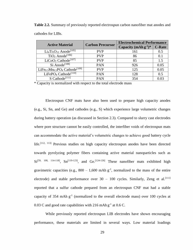
Table 2.2. Summary of previously reported electrospun carbon nanofiber mat anodes and
cathodes for LIBs.
Active Material Carbon Precursor Electrochemical Performance
Capacity (mAh g-1)* C-Rate
Li4Ti5O12 Anode[105] PVP 161 0.5
TiO2 Anode[106] PVP 86 0.1
LiCoO2 Cathode[107] PVP 85 1.5
Si Anode[108] PAN 926 0.05
LiFe0.5Mn0.5PO4 Cathode[109] PVP 125 0.05
LiFePO4 Cathode[110] PAN 128 0.5
S Cathode[111] PAN 354 0.03
* Capacity is normalized with respect to the total electrode mass
Electrospun CNF mats have also been used to prepare high capacity anodes
(e.g., Si, Sn, and Ge) and cathodes (e.g., S) which experience large volumetric changes
during battery operation (as discussed in Section 2.3). Compared to slurry cast electrodes
where pore structure cannot be easily controlled, the interfiber voids of electrospun mats
can accommodate the active material’s volumetric changes to achieve good battery cycle
life.[112, 113] Previous studies on high capacity electrospun anodes have been directed
towards pyrolyzing polymer fibers containing active material nanoparticles such as
Si[59, 108, 114-118], Sn[119-123], and Ge.[124-126] These nanofiber mats exhibited high
gravimetric capacities (e.g., 800 – 1,600 mAh g-1, normalized to the mass of the entire
electrode) and stable performance over 30 – 100 cycles. Similarly, Zeng et al.[111]
reported that a sulfur cathode prepared from an electrospun CNF mat had a stable
capacity of 354 mAh g-1 (normalized to the overall electrode mass) over 100 cycles at
0.03 C and good rate capabilities with 216 mAh g-1 at 0.6 C.
While previously reported electrospun LIB electrodes have shown encouraging
performance, these materials are limited in several ways. Low material loadings
30
corresponding to areal capacities < 1 mAh cm-2 were used in many reports on electrospun
carbon nanofiber-based electrodes, and inspection of the SEM images in these reports
indicates the fiber volume fraction of the nanofiber mats was < 0.25 which is far too low
for practical battery applications. Furthermore, since the polymer binder is removed from
the fibers during pyrolysis, these fiber mats cannot utilize high performance binders
including electronically conductive polymers[49-52] and polymers such as
poly(acrylic acid)[53], carboxymethyl cellulose[54], and alginate[55] which bind strongly to
the active material. On the other hand, the creation of carbon fibers during pyrolysis
means that electronically conductive carbon particles do not need to be added to the
electrode.
2.6 Project Objectives
To improve upon the performance of previously reported LIB electrodes, this
dissertation details the preparation and characterization of fiber mat LIB anodes and
cathodes prepared using particle/polymer electrospinning, a technique originally
developed by Pintauro and coworkers for fuel cell electrodes.[127-130] Compared to
conventional slurry cast electrodes, particle/polymer nanofiber mats have a large
electrode/electrolyte interfacial area, short Li+ transport pathways, and intra and interfiber
voids to ensure good electrolyte penetration throughout the electrode. These unique
properties allow rapid Li transport between the electrolyte and active material
nanoparticles, and thus electrospun mats should have high capacities at fast
charge/discharge rates. Furthermore, unlike previously reported electrospun electrodes,
particle/polymer fiber mats are fabricated at room temperature which preserves the

31
polymer binder, allowing the technique to incorporate new active materials and binders
as they are developed. Electrospun particle/polymer fibers can also be made porous with
a binder that absorbs electrolyte, ensuring that Li+ ions have access to the active material
nanoparticles throughout the electrode. Finally, the presence of the polymer binder allows
the mats to be compacted under high pressure without fracturing, and thus thick, densely
packed nanofiber mats can be prepared to achieve high gravimetric, areal, and volumetric
capacities. When considered collectively, these advantages provide a compelling
rationale for using particle/polymer electrospinning to prepare high performance LIB
anodes and cathodes.
32
2.7 References
[1] N. Nitta, F. Wu, J. T. Lee, G. Yushin, Mater. Today 2015, 18, 252.
[2] D. I. Iermakova, R. Dugas, M. R. Palacín, A. Ponrouch, J. Electrochem. Soc.
2015, 162, A7060.
[3] N. Nitta, G. Yushin, Part. Part. Syst. Char. 2014, 31, 317.
[4] J. B. Goodenough, Y. Kim, Chem. Mater. 2010, 22, 587.
[5] J. Towada, T. Karouji, H. Sato, Y. Kadoma, K. Shimada, K. Ui, J. Power Sources
2015, 275, 50.
[6] V. Aravindan, Y.-S. Lee, S. Madhavi, Adv. Energy Mater. 2015, 5, 1402225.
[7] J. B. Goodenough, Acc. Chem. Res. 2013, 46, 1053.
[8] Y. Liu, Y. Yang, J. Nanomater. 2016, 2016, 1.
[9] A. R. Kamali, D. J. Fray, J. New Mater. Electrochem. Syst. 2010, 13, 147.
[10] S. Goriparti, E. Miele, F. De Angelis, E. Di Fabrizio, R. Proietti Zaccaria, C.
Capiglia, J. Power Sources 2014, 257, 421.
[11] S. R. Sivakkumar, J. Y. Nerkar, A. G. Pandolfo, Electrochim. Acta 2010, 55,
3330.
[12] H. Fujimoto, K. Tokumitsu, A. Mabuchi, N. Chinnasamy, T. Kasuh, J. Power
Sources 2010, 195, 7452.
[13] J. Yang, X.-y. Zhou, J. Li, Y.-l. Zou, J.-j. Tang, Mater. Chem. Phys. 2012, 135,
445.
[14] J. R. Dahn, T. Zheng, Y. Liu, J. S. Xue, Science 1995, 270, 590.
[15] E. Buiel, J. R. Dahn, Electrochim. Acta 1999, 45, 121.
[16] J.-H. Kim, J.-S. Kim, Y.-G. Lim, J.-G. Lee, Y.-J. Kim, J. Power Sources 2011,
196, 10490.
[17] J. Zhu, D. Yang, Z. Yin, Q. Yan, H. Zhang, Small 2014, 10, 3480.
[18] D. T. Welna, L. Qu, B. E. Taylor, L. Dai, M. F. Durstock, J. Power Sources 2011,
196, 1455.
[19] M. J. Ganter, R. A. DiLeo, C. M. Schauerman, R. E. Rogers, R. P. Raffaelle, B. J.
Landi, Electrochim. Acta 2011, 56, 7272.
[20] J. E. Trevey, K. W. Rason, C. R. Stoldt, S.-H. Lee, Electrochem. Solid-State Lett.
2010, 13, A154.
[21] B. Zhang, F. Kang, J.-M. Tarascon, J.-K. Kim, Prog. Mater Sci. 2016, 76, 319.
[22] X. Su, Q. Wu, X. Zhan, J. Wu, S. Wei, Z. Guo, J. Mater. Sci. 2011, 47, 2519.
[23] C. Jiang, J. Zhang, J. Mater. Sci. Technol. 2013, 29, 97.
[24] T.-F. Yi, L.-J. Jiang, J. Shu, C.-B. Yue, R.-S. Zhu, H.-B. Qiao, J. Phys. Chem.
Solids 2010, 71, 1236.
[25] G.-N. Zhu, Y.-G. Wang, Y.-Y. Xia, Energy Environ. Sci. 2012, 5, 6652.
[26] T. Ohzuku, A. Ueda, N. Yamamoto, J. Electrochem. Soc. 1995, 142, 1431.
[27] W. Wang, M. Tian, A. Abdulagatov, S. M. George, Y. C. Lee, R. Yang, Nano
Lett. 2012, 12, 655.
[28] D. Guan, J. Li, X. Gao, C. Yuan, J. Power Sources 2014, 246, 305.
[29] G. F. Ortiz, I. Hanzu, P. Lavela, J. L. Tirado, P. Knauth, T. Djenizian, J. Mater.
Chem. 2010, 20, 4041.
[30] T. Yiping, T. Xiaoxu, H. Guangya, Z. Guoqu, Electrochim. Acta 2014, 117, 172.

33
[31] W. Wei, G. Oltean, C.-W. Tai, K. Edström, F. Björefors, L. Nyholm, J. Mater.
Chem. A 2013, 1, 8160.
[32] W. Xiong, Y. D. Wang, H. Xia, Materials Technology 2013, 28, 260.
[33] J. Kim, J. Cho, Electrochem. Solid-State Lett. 2007, 10, A81.
[34] J. Liu, K. Song, P. A. van Aken, J. Maier, Y. Yu, Nano Lett. 2014, 14, 2597.
[35] L. Shen, E. Uchaker, X. Zhang, G. Cao, Adv. Mater. 2012, 24, 6502.
[36] H. Tian, F. Xin, X. Wang, W. He, W. Han, J. Materiomics 2015, 1, 153.
[37] H. Wu, Y. Cui, Nano Today 2012, 7, 414.
[38] J. Li, N. J. Dudney, J. Nanda, C. Liang, ACS Appl. Mater. Interfaces 2014, 6,
10083.
[39] I. Ryu, J. W. Choi, Y. Cui, W. D. Nix, J. Mech. Phys. Solids 2011, 59, 1717.
[40] X. H. Liu, L. Zhong, S. Huang, S. X. Mao, T. Zhu, J. Y. Huang, ACS Nano 2012,
6, 1522.
[41] U. Kasavajjula, C. Wang, A. J. Appleby, J. Power Sources 2007, 163, 1003.
[42] M. W. Verbrugge, Y.-T. Cheng, ECS Transactions 2008, 16, 127.
[43] H. Wu, G. Chan, J. W. Choi, I. Ryu, Y. Yao, M. T. McDowell, S. W. Lee, A.
Jackson, Y. Yang, L. Hu, Y. Cui, Nat. Nanotechnol. 2012, 7.
[44] S. R. Gowda, V. Pushparaj, S. Herle, G. Girishkumar, J. G. Gordon, H. Gullapalli,
X. Zhan, P. M. Ajayan, A. L. Reddy, Nano Lett 2012, 12, 6060.
[45] S. Ohara, J. Suzuki, K. Sekine, T. Takamura, J. Power Sources 2004, 136, 303.
[46] S. Bourderau, T. Brousse, D. M. Schleich, J. Power Sources 1999, 81-82, 233.
[47] C. K. Chan, H. Peng, G. Liu, K. McIlwrath, X. F. Zhang, R. A. Huggins, Y. Cui,
Nat. Nanotechnol. 2008, 3, 31.
[48] L. Hu, H. Wu, S. S. Hong, L. Cui, J. R. McDonough, S. Bohy, Y. Cui, Chem.
Commun. 2011, 47, 367.
[49] G. Liu, S. Xun, N. Vukmirovic, X. Song, P. Olalde-Velasco, H. Zheng, V. S.
Battaglia, L. Wang, W. Yang, Adv. Mater. 2011, 23, 4679.
[50] S. J. Park, H. Zhao, G. Ai, C. Wang, X. Song, N. Yuca, V. S. Battaglia, W. Yang,
G. Liu, J. Am. Chem. Soc. 2015, 137, 2565.
[51] H. Zhao, Z. Wang, P. Lu, M. Jiang, F. Shi, X. Song, Z. Zheng, X. Zhou, Y. Fu, G.
Abdelbast, X. Xiao, Z. Liu, V. S. Battaglia, K. Zaghib, G. Liu, Nano Lett. 2014,
14, 6704.
[52] M. Wu, X. Song, X. Liu, V. Battaglia, W. Yang, G. Liu, J. Mater. Chem. A 2015,
3, 3651.
[53] A. Magasinski, B. Zdyrko, I. Kovalenko, B. Hertzberg, R. Burtovyy, C. F.
Huebner, T. F. Fuller, I. Luzinov, G. Yushin, ACS Appl. Mater. Interfaces 2010,
2, 3004.
[54] J. S. Bridel, T. Azais, M. Morcrette, J. M. Tarascon, D. Larcher, Chem. Mater.
2010, 22, 1229.
[55] I. Kovalenko, B. Zdyrko, A. Magasinski, B. Hertzberg, Z. Milicev, R. Burtovyy,
I. Luzinov, G. Yushin, Science 2011, 334, 75.
[56] D. M. Piper, J. J. Travis, M. Young, S. B. Son, S. C. Kim, K. H. Oh, S. M.
George, C. Ban, S. H. Lee, Adv. Mater. 2014, 26, 1596.
[57] N. Liu, H. Wu, M. T. McDowell, Y. Yao, C. Wang, Y. Cui, Nano Lett. 2012, 12,
3315.

34
[58] N. Liu, Z. Lu, J. Zhao, M. T. McDowell, H. W. Lee, W. Zhao, Y. Cui, Nat.
Nanotechnol. 2014, 9, 187.
[59] H. Wu, G. Zheng, N. Liu, T. J. Carney, Y. Yang, Y. Cui, Nano Lett. 2012, 12,
904.
[60] B. Hertzberg, A. Alexeev, G. Yushin, J. Am. Chem. Soc. 2010, 132, 8548.
[61] J. Wang, Y. Yu, L. Gu, C. Wang, K. Tang, J. Maier, Nanoscale 2013, 5, 2647.
[62] L.-F. Cui, L. Hu, J. W. Choi, Y. Cui, ACS Nano 2010, 4, 3671.
[63] J. Ji, H. Ji, L. L. Zhang, X. Zhao, X. Bai, X. Fan, F. Zhang, R. S. Ruoff, Adv.
Mater. 2013, 25, 4673.
[64] G.-H. Lee, S. Lee, C. W. Lee, C. Choi, D.-W. Kim, J. Mater. Chem. A 2016, 4,
1060.
[65] J. P. Maranchi, A. F. Hepp, P. N. Kumta, Electrochem. Solid-State Lett. 2003, 6,
A198.
[66] K. Zaghib, A. Guerfi, P. Hovington, A. Vijh, M. Trudeau, A. Mauger, J. B.
Goodenough, C. M. Julien, J. Power Sources 2013, 232, 357.
[67] A. Kraytsberg, Y. Ein-Eli, Adv. Energy Mater. 2012, 2, 922.
[68] P. Rozier, J. M. Tarascon, J. Electrochem. Soc. 2015, 162, A2490.
[69] C. M. Julien, A. Mauger, K. Zaghib, H. Groult, Inorganics 2014, 2, 132.
[70] D. Liu, W. Zhu, J. Trottier, C. Gagnon, F. Barray, A. Guerfi, A. Mauger, H.
Groult, C. M. Julien, J. B. Goodenough, K. Zaghib, RSC Adv. 2014, 4, 154.
[71] C.-H. Lu, H.-H. Chang, Y.-K. Lin, Ceram. Int. 2004, 30, 1641.
[72] Q. Zhang, J. Mei, X. Wang, J. Guo, F. Tang, W. Lu, J. Alloys Compd. 2014, 617,
326.
[73] Y. Zhang, H. Zhang, X. Li, H. Xu, Y. Wang, Nanotechnology 2016, 27, 155401.
[74] H. Xia, Y. Wan, W. Assenmacher, W. Mader, G. Yuan, L. Lu, NPG Asia
Materials 2014, 6, e126.
[75] W. Sun, H. Liu, Y. Liu, G. Bai, W. Liu, S. Guo, X. Z. Zhao, Nanoscale 2015, 7,
13173.
[76] F. Teng, S. Santhanagopalan, R. Lemmens, X. Geng, P. Patel, D. D. Meng, Solid
State Sciences 2010, 12, 952.
[77] S. Tintignac, R. Baddour-Hadjean, J. P. Pereira-Ramos, R. Salot, Electrochim.
Acta 2014, 146, 472.
[78] R. A. Davoglio, K. Irikura, S. R. Biaggio, N. Bocchi, R. C. Rocha-Filho, J. Solid
State Electrochem. 2016, 20, 2019.
[79] A. Bunting, S. Uhlenbruck, D. Sebold, H. P. Buchkremer, R. Vaßen, ACS Appl.
Mater. Interfaces 2015, 7, 22594.
[80] L. Chen, L. L. Shaw, J. Power Sources 2014, 267, 770.
[81] L. Borchardt, M. Oschatz, S. Kaskel, Chemistry 2016, 22, 7324.
[82] S.-K. Lee, Y. J. Lee, Y.-K. Sun, J. Power Sources 2016, 323, 174.
[83] L. Ji, M. Rao, H. Zheng, L. Zhang, Y. Li, W. Duan, J. Guo, E. J. Cairns, Y.
Zhang, J. Am. Chem. Soc. 2011, 133, 18522.
[84] G. Zhou, L.-C. Yin, D.-W. Wang, L. Li, S. Pei, I. R. Gentle, F. Li, H.-M. Cheng,
ACS Nano 2013, 7, 5367.
[85] Y. Qiu, W. Li, W. Zhao, G. Li, Y. Hou, M. Liu, L. Zhou, F. Ye, H. Li, Z. Wei, S.
Yang, W. Duan, Y. Ye, J. Guo, Y. Zhang, Nano Lett. 2014, 14, 4821.
35
[86] Z. Wang, Y. Dong, H. Li, Z. Zhao, H. B. Wu, C. Hao, S. Liu, J. Qiu, X. W. Lou,
Nat. Commun. 2014, 5, 5002.
[87] F. Wu, J. Chen, R. Chen, S. Wu, L. Li, S. Chen, T. Zhao, J. Phys. Chem. C 2011,
115, 6057.
[88] Z. Wei Seh, W. Li, J. J. Cha, G. Zheng, Y. Yang, M. T. McDowell, P. C. Hsu, Y.
Cui, Nat. Commun. 2013, 4, 1331.
[89] X. Liang, L. F. Nazar, ACS Nano 2016, 10, 4192.
[90] N. Ding, S. W. Chien, T. S. A. Hor, Z. Liu, Y. Zong, J. Power Sources 2014, 269,
111.
[91] J. F. Cooley, United States of America Patent 692,631, 1902.
[92] J. Doshi, D. H. Reneker, J. Electrostat. 1995, 35, 151.
[93] D. H. Reneker, I. Chun, Nanotechnology 1996, 7, 216.
[94] S. Cavaliere, S. Subianto, I. Savych, D. J. Jones, J. Rozière, Energy Environ. Sci.
2011, 4, 4761.
[95] P. Wang, D. Zhang, F. Ma, Y. Ou, Q. N. Chen, S. Xie, J. Li, Nanoscale 2012, 4,
7199.
[96] N. T. Xuyen, E. J. Ra, H.-Z. Geng, K. K. Kim, K. H. An, Y. H. Lee, J. Phys.
Chem. B 2007, 111, 11350.
[97] S. H. Park, C. Kim, Y. O. Choi, K. S. Yang, Carbon 2003, 41, 2655.
[98] S. X. Wang, L. Yang, L. P. Stubbs, X. Li, C. He, ACS Appl. Mater. Interfaces
2013, 5, 12275.
[99] Y. Chen, X. Li, K. Park, J. Song, J. Hong, L. Zhou, Y. W. Mai, H. Huang, J. B.
Goodenough, J. Am. Chem. Soc. 2013, 135, 16280.
[100] L. Ji, X. Zhang, Electrochem. Commun. 2009, 11, 684.
[101] D. Nan, J.-G. Wang, Z.-H. Huang, L. Wang, W. Shen, F. Kang, Electrochem.
Commun. 2013, 34, 52.
[102] L. Ji, X. Zhang, Nanotechnology 2009, 20, 155705.
[103] S.-H. Park, B.-K. Kim, W.-J. Lee, J. Power Sources 2013, 239, 122.
[104] L. Ji, Y. Yao, O. Toprakci, Z. Lin, Y. Liang, Q. Shi, A. J. Medford, C. R. Millns,
X. Zhang, J. Power Sources 2010, 195, 2050.
[105] H. Xu, X. Hu, Y. Sun, W. Luo, C. Chen, Y. Liu, Y. Huang, Nano Energy 2014,
10, 163.
[106] R. Qing, W. Sigmund, Ceram. Int. 2014, 40, 5665.
[107] H.-W. Lu, L. Yu, W. Zeng, Y.-S. Li, Z.-W. Fu, Electrochem. Solid-State Lett.
2008, 11, A140.
[108] K. Fu, L. Xue, O. Yildiz, S. Li, H. Lee, Y. Li, G. Xu, L. Zhou, P. D. Bradford, X.
Zhang, Nano Energy 2013, 2, 976.
[109] R. von Hagen, H. Lorrmann, K.-C. Möller, S. Mathur, Adv. Energy Mater. 2012,
2, 553.
[110] C. Zhang, L. Yao, Y. Qiu, J. Appl. Polym. Sci. 2016, 133, 43001.
[111] L. Zeng, Y. Jiang, J. Xu, M. Wang, W. Li, Y. Yu, Nanoscale 2015, 7, 10940.
[112] L. Liu, J. Lyu, T. Li, T. Zhao, Nanoscale 2016, 8, 701.
[113] H.-G. Wang, S. Yuan, D.-L. Ma, X.-B. Zhang, J.-M. Yan, Energy Environ. Sci.
2015, 8, 1660.
[114] Y. Liu, K. Huang, Y. Fan, Q. Zhang, F. Sun, T. Gao, Z. Wang, J. Zhong,
Electrochim. Acta 2013, 102, 246.
36
[115] L. Ji, X. Zhang, Energy Environ. Sci. 2010, 3, 124.
[116] L. Xue, K. Fu, Y. Li, G. Xu, Y. Lu, S. Zhang, O. Toprakci, X. Zhang, Nano
Energy 2013, 2, 361.
[117] Y. Xu, Y. Zhu, F. Han, C. Luo, C. Wang, Adv. Energy Mater. 2015, 5, 1400753.
[118] Z. Favors, H. H. Bay, Z. Mutlu, K. Ahmed, R. Ionescu, R. Ye, M. Ozkan, C. S.
Ozkan, Sci. Rep. 2015, 5, 8246.
[119] Y. Yu, Q. Yang, D. Teng, X. Yang, S. Ryu, Electrochem. Commun. 2010, 12,
1187.
[120] I. Meschini, F. Nobili, M. Mancini, R. Marassi, R. Tossici, A. Savoini, M. L.
Focarete, F. Croce, J. Power Sources 2013, 226, 241.
[121] F. Nobili, I. Meschini, M. Mancini, R. Tossici, R. Marassi, F. Croce, Electrochim.
Acta 2013, 107, 85.
[122] X. Xia, X. Wang, H. Zhou, X. Niu, L. Xue, X. Zhang, Q. Wei, Electrochim. Acta
2014, 121, 345.
[123] S. Kim, J.-H. Choi, D.-S. Lim, J.-H. Lee, I.-D. Kim, J. Electroceram. 2014, 32,
261.
[124] W. Wang, Y. Xiao, X. Wang, B. Liu, M. Cao, ChemSusChem 2014, 7, 2914.
[125] W. Li, Z. Yang, J. Cheng, X. Zhong, L. Gu, Y. Yu, Nanoscale 2014, 6, 4532.
[126] Y. W. Lee, D. M. Kim, S. J. Kim, M. C. Kim, H. S. Choe, K. H. Lee, J. I. Sohn,
S. N. Cha, J. M. Kim, K. W. Park, ACS Appl. Mater. Interfaces 2016, 8, 7022.
[127] W. Zhang, P. N. Pintauro, ChemSusChem 2011, 4, 1753.
[128] M. Brodt, R. Wycisk, P. N. Pintauro, J. Electrochem. Soc. 2013, 160, F744.
[129] M. Brodt, T. Han, N. Dale, E. Niangar, R. Wycisk, P. Pintauro, J. Electrochem.
Soc. 2014, 162, F84.
[130] M. Brodt, R. Wycisk, N. Dale, P. Pintauro, J. Electrochem. Soc. 2016, 163, F401.
37
CHAPTER III
ELECTROSPUN TITANIA-BASED FIBERS FOR HIGH AREAL CAPACITY LI-ION
BATTERY ANODES
Adapted from E. C. Self, R. Wycisk, P. N. Pintauro, J. Power Sources 2015, 282, 187
with permission from Elsevier.
3.1 Introduction
Despite widespread commercial success, Li-ion battery (LIB) technologies
require significant improvements to keep pace with increasing energy demands.[1] The
scientific community has dedicated considerable time and resources to develop superior
LIB materials, most notably replacements for the graphite anode. Currently, LIB anode
performance is limited in three primary ways: (i) lithium capacity, (ii) cycle life, and
(iii) rate capabilities. To address the Li capacity problem, Li-alloying materials such as
silicon have been examined with some success. In these studies, high capacities (near the
theoretical limit of 3,579 mAh gSi-1) were obtained but at the expense of reduced lifetimes
due to Si volume changes during charge/discharge cycling.[2] The use of nanostructured
Si anodes in the form of nanowires, nanotubes, nanofibers, and nanoparticles improved
cycle life and rate capabilities, but these nanomaterials often have low tap densities,
resulting in poor volumetric and areal capacities.[3-17]
Titania has gained attention as a potential LIB anode material for two primary
reasons: (i) TiO2 anodes exhibit outstanding lifetimes due to limited volume changes
38
during battery cycling (< 4 % for anatase TiO2 vs. ~ 8 % for graphite) and
(ii) the high operating potential of a TiO2 anode (1.5 – 1.8 V vs. Li/Li+) minimizes safety
issues associated with Li dendrite formation and solid-electrolyte interface (SEI)
formation encountered with graphite materials.[18-20] These advantages are
counterbalanced by the low lithium capacity of titania. The lithiation/delithiation reaction
with TiO2 is shown in equation 3.1.
TiO2 + xLi+ + xe- ↔ LixTiO2 (3.1)
Assuming complete lithiation (x = 1), titania’s theoretical capacity is 335 mAh g-1, but
attainable capacities are generally only ~ 168 mAh g-1 (x = 0.50) due to strong repulsive
forces among Li+ ions.[18] In comparison, the operational capacity of graphite is
~ 340 mAh g-1. Another drawback of TiO2 anodes is their poor rate capabilities arising
from poor electronic conductivity (~ 1x10-12 S m-1) and a low lithium diffusion
coefficient (~ 1x10-15 cm2 s-1).[18, 21] Some improvements in rate capabilities have been
attained when TiO2 is fabricated into nanowires and nanotubes, but these approaches are
limited to low areal capacities (< 1 mAh cm-2).[22-26] For example, Wei et al.[26] tested a
TiO2 nanotube anode and reported excellent rate capabilities with ~ 45 % capacity
retention at 5 C, but the areal capacity (0.6 mAh cm-2) was about 5-times lower than that
of graphite anodes (2.5 – 3.5 mAh cm-2). To effectively compete with commercial
graphite materials, titania anodes with areal capacities ≥ 3 mAh cm-2 at fast
charge/discharge rates (≥ 2 C) must be developed.[27]
Battery researchers often focus on an electrode’s gravimetric and volumetric
capacities. While these properties are important for weight- and volume-sensitive
applications, they do not always provide an indication of an electrode’s usefulness for
39
practical batteries. For example, Wu et al.[6] prepared double-walled Si nanotube anodes
that exhibited outstanding gravimetric and volumetric capacities of 1,780 mAh g-1 and
2,000 mAh cm-3, respectively. Despite these impressive material-normalized metrics, the
anode was limited to loadings < 0.1 mg cm-2, corresponding to an areal capacity of only
0.178 mAh cm-2 (approximately 17 times lower than commercial graphite anodes).
Unless material loading is reported separately, a mass- or volume-normalized capacity
conceals the electrode’s areal loading (i.e., mg cm-2), an important parameter which
directly impacts performance. Especially for anodes containing large-volume changing
hosts (e.g., Si), simply increasing the material loading does not always provide good
performance and a practical areal capacity. An electrode may perform well at a low areal
loading but becomes less useful at higher loadings due to large internal stresses and/or
transport resistances (i.e., low Li+ and/or electronic conductivity).[27] Furthermore, a low
areal loading increases the amount of inactive components (i.e., current collectors,
separators, cell packaging, etc.) for full cell construction. Nitta and Yushin recently
addressed these concerns and emphasized that areal capacity is an important metric for
practical battery electrodes.[27] New electrode architectures should be prepared with areal
capacities comparable to commercial graphite anodes (2.5 – 3.5 mAh cm-2) to assess their
practicality for consumer devices.
3D porous anodes show promise for achieving both high areal capacities and short
recharge times. Complete electrolyte penetration throughout a porous anode results in
good active material utilization even at high loadings. For example, Hu et al.[28] prepared
600 µm thick Li5Ti4O12 anodes using a porous textile substrate. They reported high areal
capacities but only at slow discharge rates (e.g., ~ 27 mAh cm-2 at ~ 0.06 C). In addition
40
to high areal capacity, Vu et al.[29] propose that a 3D porous network can enhance
electrode rate capabilities. Previous studies suggest that conventional electrodes are
limited by Li+ concentration polarization under fast charging currents.[30, 31] A 3D porous
structure addresses this limitation by utilizing a large electrode/electrolyte interfacial area
to limit Li+ depletion near the electrode during charging. This 3D structure enhances Li+
transport within the pores and thus improves the electrode’s rate capabilities.
Despite the promising performance of 3D porous LIB anodes, no reports to date
have achieved high areal capacities (≥ 3 mAh cm-2) at fast charge/discharge rates (≥ 2 C).
To address these issues, the present study investigates the fabrication and use of
electrospun fibrous anodes containing TiO2 and carbon nanoparticles with a
poly(acrylic acid) binder. Electrolyte penetration throughout the porous mat and short Li+
transport pathways between the electrolyte and TiO2 nanoparticles in the radial fiber
direction allow for production of thick electrodes with a high areal capacity and excellent
rate capabilities.
A key innovative aspect of the present study is the use of electrospun
particle/polymer fiber mat anodes in a LIB. Electrospinning has been shown to be an
inexpensive and scalable technique for fabricating high performance nanofibrous energy
storage and conversion electrodes. For LIB applications, all prior electrospinning studies
have been directed towards the pyrolysis of polymer fibers to create an electronically
conductive carbon-based nanofiber network containing a Li host.[9, 11, 32-35] Zhang and
coworkers,[9, 11] for example, prepared and characterized anodes containing silicon
nanoparticles in carbon nanofibers. These materials achieved capacities up to
850 mAh g-1, but neither areal capacity nor rate capabilities were investigated. Similarly,
41
Zhao et al.[36] electrospun a TiO2 nanoparticle/carbon nanofiber anode which exhibited
stable capacities at charge/discharge rates up to 30 C, but the authors did not discuss areal
capacity or material loading effects.
The approach taken in the present study builds upon the work of Pintauro and
coworkers who used particle/polymer electrospinning to fabricate high performance
oxygen reduction Pt/C nanofiber cathodes for hydrogen/air fuel cells.[37, 38] In a manner
similar to the fuel cell electrode work, composite fiber anodes for LIBs were prepared
using particle/polymer electrospinning. Potential advantages of electrospun anodes over
conventional slurry cast electrodes include: (i) a large electrode/electrolyte interfacial
area for enhanced electrochemical oxidation/reduction kinetics, (ii) a controllable
interfiber void volume to ensure good electrolyte infiltration into the electrode, and (iii)
micron/sub-micron fibers with high nanoparticle content and short Li+ transport
pathways.[32, 39] Furthermore, the method can be adapted to a wide selection of
particle/polymer combinations, making this a robust technology that is capable of
incorporating new materials as they are developed.
Herein we present LIB performance data for an electrospun fiber anode
containing TiO2 nanoparticles, carbon powder, and a poly(acrylic acid) binder (from
hereon referred to as TiO2/C/PAA). TiO2 was chosen as an active material due to its
excellent cyclability, its minimal volume changes upon cycling, and its avoidance of SEI
layer formation. Thin and thick anodes were characterized in terms of stability and rate
capabilities; thin electrodes had an areal capacity of 0.099 mAh cm-2 and a thickness of
50 µm whereas thick electrodes had an areal capacity of 1.5 – 3.9 mAh cm-2 and a
thickness of 600 – 1,400 µm. The performance of the electrospun material is compared

42
with that of conventional slurry cast electrodes of the same composition. These results are
also contrasted with TiO2, graphite, and Si anodes reported in the literature.
3.2 Experimental
Anode slurries were prepared by mixing titania nanoparticles (anatase, 15 nm, US
Research Nanomaterials, Inc), conductive carbon black (Vulcan XC72R, Fuel Cell
Store, Inc.), and poly(acrylic acid) (PAA, Mv = 450,000 g mol-1, Sigma-Aldrich) in
1-propanol with a fixed composition of 19 wt % solids where the TiO2/C/PAA weight
ratio was 40/25/35. Electrodes were prepared from this mixture by either:
(i) conventional slurry casting or (ii) electrospinning a nonwoven fiber mat. Slurry cast
anodes were prepared by painting the electrode mixture onto Cu foil (9 µm, MTI Corp).
The liquid slurries were stabilized at ambient conditions for at least 2 h to allow for
partial solvent evaporation and subsequently dried overnight at 60 °C under vacuum.
Electrospinning was conducted at room temperature on a custom-built rotating and
oscillating drum collection apparatus as described elsewhere.[37] Well-formed fibers were
deposited on an aluminum foil sheet at the following conditions: (i) 1.00 mL h-1 solution
flow rate, (ii) 8 – 9 kV bias voltage, (iii) 8.0 cm spinneret-to-collector distance, and (iv) a
relative humidity between 10 – 20 %. Small adjustments in bias voltage and relative
humidity were needed to maintain batch-to-batch reproducibility of the fiber structure.
Top-down surface images of mats were collected and analyzed by scanning electron
microscopy (Hitachi S4200 SEM) after gold sputtering for 90 s.
The fiber volume fraction in an electrospun mat was determined from the ratio of
the fiber mat density and the density of a slurry cast electrode. The as-spun mats typically

43
had a fiber volume fraction < 0.30, which was increased by mechanical compaction on a
hydraulic press (typical compaction conditions were ~ 5 MPa for ~ 10 s). Unless
otherwise stated, the fiber volume fraction of electrospun anodes was in the range of
0.40 – 0.60. The compacted electrospun mats were sufficiently robust such that they
could be tested in a coin cell without the need for a Cu foil current collector.
CR2032 half cells were assembled in an argon-filled glovebox using a
titania-based slurry cast or electrospun working electrode (dried overnight at 60 °C under
vacuum) and a Li metal counter/reference electrode. The electrolyte was 1.0 M LiPF6 in a
mixture of ethylene carbonate, dimethyl carbonate, and diethyl carbonate (1/1/1 by
volume, MTI Corp.). Two sheets of Celgard 2500 soaked in the electrolyte were used as a
membrane separator. For electrospun fiber anodes, the desired loading was achieved by
stacking several layers of uncompacted electrospun mats followed by mechanical
compression as described above. For slurry cast electrodes, the amount of material
painted onto the Cu foil was varied to control loading, which was determined by
subtracting the Cu substrate mass from the total electrode mass. In the present study,
electrodes were prepared with material loadings ranging from to 1.4 to 54.1 mg cm-2
(which includes the mass of TiO2, carbon and PAA). Several drops of electrolyte were
added to electrodes with high mass loadings (> 20 mg cm-2) to ensure complete
electrolyte infiltration throughout the electrode. Cells were crimped at 1,000 psi and
evaluated electrochemically at room temperature after a 24 h resting period.
Cells were analyzed by cyclic voltammetry, where the anode was polarized
between 1.0 and 2.6 V at a scan rate of 0.5 mV s-1 using a Gamry Reference 3000
potentiostat. During galvanostatic charge/discharge experiments, cells were cycled

44
between 1.0 – 2.6 V. To investigate anode rate capabilities, cells were cycled 5 times at
current densities corresponding to 0.1 – 5 C, and the capacity during the 5th cycle was
recorded. Battery cycling experiments were performed on an 8-channel battery tester
(5V/1mA, MTI Corp.) and a Gamry potentiostat (for high C-rate testing). At least two
coin cells were tested for each sample to assess the reproducibility of these experiments.
The electrochemical performance of each sample was reproducible within approximately
15 – 20 % among independent coin cell tests. Selected cells were disassembled after
cycling, and the anodes were washed thoroughly with diethyl carbonate for post-mortem
SEM imaging.
C-rates are based on a theoretical capacity of 335 mAh g-1 TiO2
(i.e., 335 mA gTiO2-1 corresponds to 1 C). Unless otherwise indicated, electrochemical
capacities refer to TiO2 delithiation. Areal capacities are based on the electrode’s
geometric footprint, and all potentials are referenced vs. Li/Li+.
3.3 Results and Discussion
A scanning electron microscopy (SEM) image of an as-spun electrospun mat
containing titania nanoparticles and carbon black with a poly(acrylic acid) (PAA) binder
(average fiber diameter = 1.4 µm) is shown in Figure 3.1a. The fiber volume fraction of
the as-spun mat was very low (< 0.30), so a compaction step on a hydraulic press was
used to increase the material’s density. A compacted anode with a fiber volume fraction
of 0.54 is shown in Figure 3.1b. Compared to a slurry electrode of the same composition
(Figure 3.1c), the electrospun material contained large interfiber void spaces which allow
for complete electrolyte penetration throughout the porous structure. The presence of
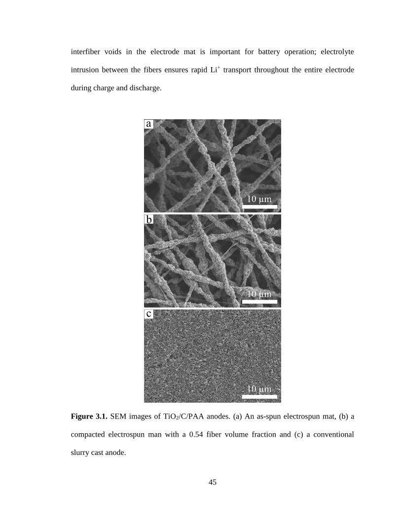
45
interfiber voids in the electrode mat is important for battery operation; electrolyte
intrusion between the fibers ensures rapid Li+ transport throughout the entire electrode
during charge and discharge.
Figure 3.1. SEM images of TiO2/C/PAA anodes. (a) An as-spun electrospun mat, (b) a
compacted electrospun man with a 0.54 fiber volume fraction and (c) a conventional
slurry cast anode.

46
The electrospun composites were characterized as LIB anodes using cyclic
voltammetry (CV) and galvanostatic charge/discharge experiments. Representative cyclic
voltammograms shown in Figure 3.2a exhibit peaks at 2.17 and 1.66 V vs. Li/Li+, which
correspond to TiO2 anatase lithiation and delithiation, respectively.[40] Some peak shifting
was observed during the first few scans, as has been reported by others, but the
voltammograms stabilized after 10 cycles.[40] Forward and reverse peak currents were
within ~ 5 % of one another, indicating good reversibility of the lithiation reaction. The
galvanostatic charge/discharge curves shown in Figure 3.2b exhibit lithiation/delithiation
potential plateaus which correlate well with the CV peaks. During the first delithiation
cycle, the capacity of an electrospun anode (as averaged over numerous samples) was
73 ± 5 mAh g-1 (i.e., 183 mAh gTiO2-1). An irreversible capacity loss of 35 % during the
first cycle is attributed to anatase structural defects which trap Li inside TiO2 interstitial
spaces.[20, 41] Ortiz et al.[20] reported a similar irreversible capacity loss of 29 % for a TiO2
nanotube anode. Despite this initial loss, the electrospun material exhibited excellent
stability with a reversible capacity of 62 mAh g-1 after 50 cycles. The voltammograms
and charge/discharge curves agree well with those reported by others for TiO2-based
anodes, which indicates: (i) the electrospinning process did not adversely affect
fundamental lithiation/delithiation properties of TiO2 and (ii) there was sufficient carbon
powder in the fibers for electron access to all TiO2 nanoparticles.[40, 42] The gravimetric
capacity of the electrospun anode was lower than other systems reported in the literature
(typically > 100 mAh g-1) due to the low titania content of the fibers (40 wt %). The
electrode composition in this study (TiO2/C/PAA weight ratio of 40/25/35) was required
to obtain well-formed fibers with good electrical conductivity. At least 25 wt % polymer
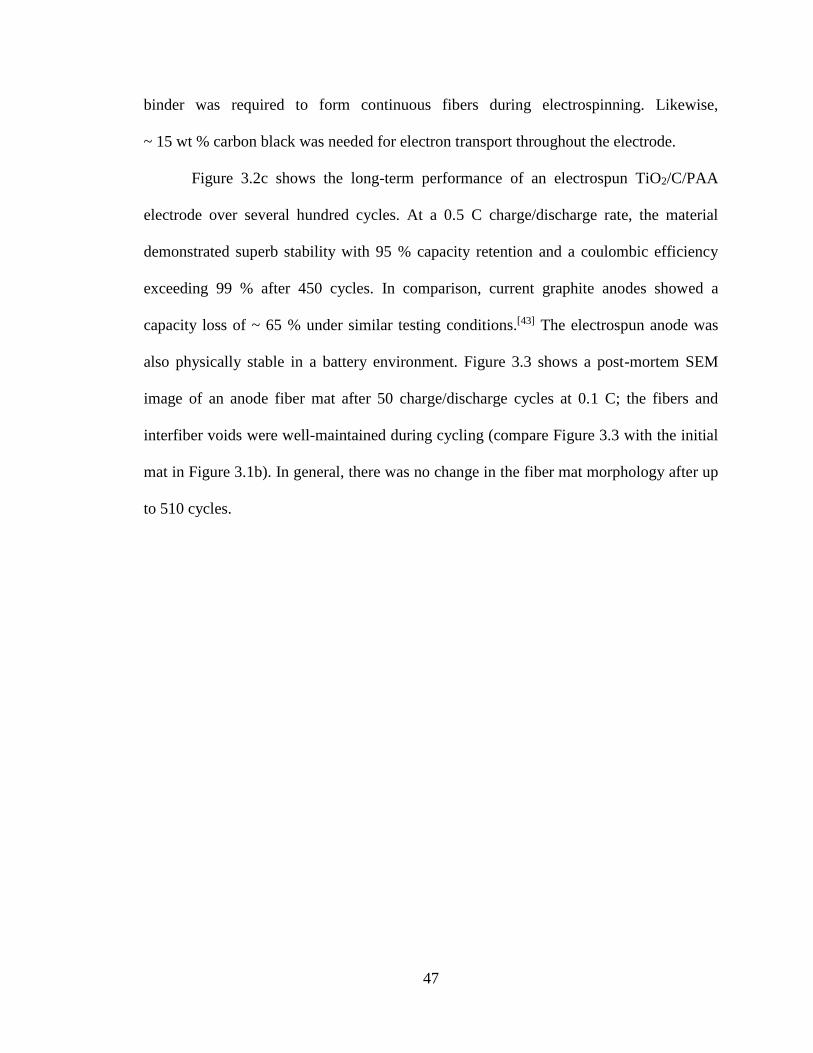
47
binder was required to form continuous fibers during electrospinning. Likewise,
~ 15 wt % carbon black was needed for electron transport throughout the electrode.
Figure 3.2c shows the long-term performance of an electrospun TiO2/C/PAA
electrode over several hundred cycles. At a 0.5 C charge/discharge rate, the material
demonstrated superb stability with 95 % capacity retention and a coulombic efficiency
exceeding 99 % after 450 cycles. In comparison, current graphite anodes showed a
capacity loss of ~ 65 % under similar testing conditions.[43] The electrospun anode was
also physically stable in a battery environment. Figure 3.3 shows a post-mortem SEM
image of an anode fiber mat after 50 charge/discharge cycles at 0.1 C; the fibers and
interfiber voids were well-maintained during cycling (compare Figure 3.3 with the initial
mat in Figure 3.1b). In general, there was no change in the fiber mat morphology after up
to 510 cycles.
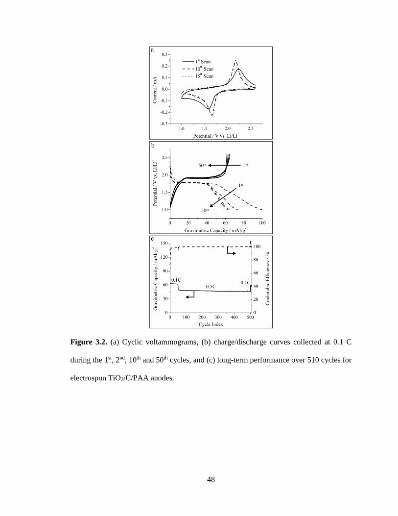
48
Figure 3.2. (a) Cyclic voltammograms, (b) charge/discharge curves collected at 0.1 C
during the 1st, 2nd, 10th and 50th cycles, and (c) long-term performance over 510 cycles for
electrospun TiO2/C/PAA anodes.

49
Figure 3.3. SEM of an electrospun anode fiber electrode after 50 charge/discharge cycles
at 0.5 C.
In addition to long-term stability, LIB anodes must possess good rate capabilities
for fast recharging. The effect of C-rate on capacity retention (i.e., capacity normalized
with respect to that measured at 0.1 C) for an electrospun and a conventional slurry cast
anode was assessed at two different mass loading ranges: low loading
(1.4 – 2.6 mg cm-2) and high loading (20.1 – 21.9 mg cm-2). With a low mass loading
(Figure 3.4a), both the fiber and slurry anodes had reversible capacities ~ 73 mAh g-1 at
0.1 C and similar capacity losses up to 5 C. Battery capacity losses at higher currents are
a well-known phenomena and are due to internal resistance together with activation and
concentration overpotential losses.[44] Since both morphologies demonstrated similar
performance declines with increasing C-rate, Li+ transport in the electrolyte is not likely
rate limiting at the low material loadings. However, at a higher loading of
20.1 – 21.9 mg cm-2, significant differences between the electrospun and slurry cast

50
systems were apparent, as shown in Figure 3.4b. Both electrodes again attained capacities
~ 73 mAh g-1 at 0.1 C, but the slurry cast electrode lost 92 % of this capacity at 5 C. In
contrast, the electrospun material demonstrated dramatically improved performance and a
4-fold higher capacity retention at 5 C (31 % vs. 7.9 %). Slow Li+ transport throughout
the interior of the thick anode (i.e., high mass loading) is undoubtedly limiting the
performance of the slurry cast anode. This limitation was not seen for the fibrous anode
where complete electrolyte intrusion into the interfiber void space provided: (i) a large
3D electrode/electrolyte interfacial area and (ii) short Li+ transport pathways between the
electrolyte and TiO2 nanoparticles in the radial fiber direction. Interestingly, both the low
and high loading electrospun anodes maintained the same capacity retention up to 2 C.
This behavior indicates that the 3D interfiber voids promoted effective Li+ transport
throughout the anode. The unique morphology of the electrospun electrodes provides
superior rate capabilities at high loadings compared to a conventional slurry cast system.
Figure 3.4. Normalized capacity vs. C-rate for different electrospun and slurry cast
electrodes. (a) Low mass loading, and (b) high mass loading. Capacities are normalized
with respect to the capacity at 0.1 C.

51
To further investigate the effect of material loading on anode performance,
particle/polymer electrospinning was used to prepare ultra-thick electrodes with high
areal capacities. The investigation of thick slurry cast LIB anodes (> 100 µm) has thus far
been limited due to difficulties in making such electrodes (e.g., material cracking and
poor adhesion to the current collector) when conventional techniques are employed.[45, 46]
For an electrospun fiber anode, these limitations are circumvented; multiple fiber mats
can be easily stacked to create an anode of any desired areal loading. The areal capacity
dependence on C-rate for electrospun anodes of four thicknesses
(50, 600, 1,000 and 1,400 m, corresponding to areal capacities of 0.099, 1.5, 2.9, and
3.9 mAh cm-2, respectively) is shown in Figure 3.5. Note that the 50 and 600 µm samples
are the same as those represented in Figure 3.4. All electrodes in Figure 3.5 exhibited a
gravimetric capacity of ~ 73 mAh g-1 at 0.1 C with no capacity fade during cycling. For
the 1,400 m thick fiber anode (54.1 mg cm-2 loading), a remarkably high capacity of
2.5 mAh cm-2 was achieved at 1 C (vs. 3.9 mAh cm-2 at 0.1 C). These areal capacities are
comparable to those of commercial graphite anodes (2.5 – 3.5 mAh cm-2).[27] A steeper
decline in capacity with C-rate was observed for the 1.0 and 1.4 mm thick electrodes due
to a higher ohmic potential drop within the electrode. This observation indicates a
tradeoff between energy and power densities for thick electrodes with high mass
loadings.

52
Figure 3.5. Areal capacity as a function of C-rate for electrospun anodes of different
thicknesses (50 µm = 1.38 mg cm-2, 600 µm = 21.9 mg cm-2, 1.0 mm = 40.2 mg cm-2, and
1.4 mm = 54.1 mg cm-2).
The performance of the ultra-thick electrospun anodes is superior to other
electrodes of comparable thickness, as reported in the literature. For example,
Wang et al.[45] prepared a 1.2 mm thick anode by depositing a carbon layer onto 3D Cu
foam. This material attained a high areal capacity of 17 mAh cm-2 at 0.05 C but showed a
steady capacity fade upon cycling at 0.5 C. Evanoff et al.[46] characterized a 1 mm thick
anode containing Si coated carbon nanotubes where the capacity (3,300 mAh g-1) was
stable at 0.2 C, but areal capacities were not reported. This anode exhibited poor rate
capabilities at 0.5 C where it lost 37 % of its low-rate capacity. Neither Wang et al.[45] nor
Evanoff et al.[46] examined charge/discharge currents greater than 0.5 C. For comparison
with the present study, the 1.4 mm electrospun fiber anode showed stable cycling and
maintained 84 % of its capacity at 0.5 C. The superior performance of the thick

53
electrospun anodes is again attributed to complete electrolyte intrusion between the fibers
and short Li+ transport pathways.
The performance of an electrospun titania anode is compared to published data for
anodes containing either TiO2, commercial graphite, or Si in Figure 3.6.[6, 17, 26, 47, 48] At
charge/discharge rates up to 2 C, the electrospun anodes exhibited superior performance.
It is important to note that Si materials, heralded for their excellent gravimetric capacity
(> 1,000 mAh g-1), are often limited to very low loadings and areal capacities
(< 1 mAh cm-2). While the electrospun system in the present study had higher areal
capacities at rates up to 2 C, it exhibited a lower 5 C capacity (0.20 mAh cm-2) as
compared to that of the Si/CNT nanofibers (0.63 mAh cm-2) and TiO2 nanotubes
(0.26 mAh cm-2). Optimizing the fiber mat composition (i.e., minimizing binder and
carbon content) and/or morphology (i.e., identifying the preferred fiber diameter and fiber
volume fraction) is anticipated to provide higher areal capacities at charge/discharge rates
> 2 C.

54
Figure 3.6. Comparison of areal capacity and rate capabilities of a particle/polymer
electrospun system with several other reports in the literature.
The volumetric capacity of electrospun anodes was also considered since this
measure of electrode performance is critically important for space-limited applications
such as electric vehicle batteries. Table 3.1 lists the volumetric capacities of two
electrospun anodes with fiber volume fractions of 0.60 and 0.87 and of one slurry cast
electrode. At 0.1 C, the electrospun anode with a fiber volume fraction of 0.60 exhibited
a volumetric capacity of 28.7 mAh cm-3 which is lower than the 47.9 mAh cm-3 for the
slurry cast system due to the void volume between fibers in the electrospun electrode.
However, since the electrospun material had superior rate capabilities, its volumetric
capacity at 2 C was equal to that of a slurry cast anode (17.5 mAh cm-3for each). A
further improvement in the volumetric capacity of the electrospun anode was achieved by
using a high compaction pressure to increase the mat’s fiber volume fraction to 0.87. This
highly compacted anode had s a 2 C volumetric capacity of 21.2 mAh cm-3 which

55
exceeds that of the slurry cast electrode. For comparison, a graphite anode report by
Sivakkumar et al.[47] had a volumetric capacity of ~ 27 mAh cm-3 at 2 C.
Table 3.1. Volumetric capacity of electrospun and slurry cast titania-based anodes.
Anode Typea Fiber Volume Fraction Volumetric Capacity (mAh cm-3)
Theoreticalb 0.1 C 1 C 2 C
Electrospun
(low compaction)c 0.60 53.2 28.7 21.0 17.5
Electrospun
(high compaction) 0.87 76.9 39.0 27.5 21.2
Slurry Cast -- 88.6 47.9 28.5 17.5 a All anodes contain 40/25/35 TiO2/C/PAA by weight. b Calculated based on 335 mAh gTiO2
-1 c Same electrode type as presented in Figures 3.2, 3.4, 3.5, and 3.6.
3.4 Conclusions
Particle/polymer fiber electrospinning was used for the first time to prepare high
performance TiO2-based LIB anodes. This approach utilized TiO2 nanoparticles as a
lithium host and carbon black for electronic conduction. The use of carbon black powder
rather than a pyrolyzed polymer nanofiber distinguishes the anodes in this study from
previous electrospun LIB electrode investigations. The method demonstrated here is
robust and can be easily adapted to accommodate a variety of Li host nanoparticles and
polymer binders. In the present study, composite fiber mats containing titania and carbon
nanoparticles with a poly(acrylic acid) binder were fabricated and tested as LIB anodes.
Anode mats were prepared with an average fiber diameter of 1.4 µm and a fiber
volume fraction of 0.50 – 0.60. The material exhibited a gravimetric capacity of
73 mAh g-1 at 0.1 C and showed excellent stability, with 95 % capacity retention and a

56
coulombic efficiency exceeding 99 % after 450 cycles. Compared to a traditional slurry
cast electrode of the same composition at a material loading of 20.1 – 21.9 mg cm-2, the
electrospun fiber anode maintained a 4-fold higher capacity at a 5 C charge/discharge
rate. Electrospun anodes with thicknesses exceeding 1 mm and areal capacities up to
3.9 mAh cm-2 were also prepared. Even at a 1 C charge/discharge rate, the thick anodes
displayed a high capacity (2.5 mAh cm-2) which is comparable to that of commercial
graphite anodes. Fibrous anodes with thicknesses of 1.0 and 1.4 mm exhibited lower areal
capacities at 5 C compared to thinner materials due to greater ohmic resistances,
indicating a tradeoff between areal capacity and rate capabilities. Compared to TiO2,
graphite, and Si-based LIB anodes reported in the literature, the electrospun composite
fibers achieved higher areal capacities at charge/discharge rates up to 2 C. A highly
compacted electrospun anode with a fiber volume fraction of 0.87 had a 2 C volumetric
capacity of 21.2 mAh cm-3 which exceeds that of a slurry cast electrode
(17.5 mAh cm-3).
The excellent performance of the fibrous anodes is attributed to: (i) complete
electrolyte infiltration throughout the interfiber void space of an anode mat and (ii) short
Li+ transport pathways between the electrolyte and TiO2 nanoparticles in the radial fiber
direction. Further improvements in capacity at high C-rates are expected after optimizing
the anode fiber mat composition (e.g., minimizing carbon and binder content while
maintaining good electrical conduction and mechanical stability) and morphology
(e.g., fiber diameter and fiber volume fraction).
57
3.5 References
[1] M. Armand, J.-M. Tarascon, Nature 2008, 451, 652.
[2] U. Kasavajjula, C. Wang, A. J. Appleby, J. Power Sources 2007, 163, 1003.
[3] C. K. Chan, H. Peng, G. Liu, K. McIlwrath, X. F. Zhang, R. A. Huggins, Y. Cui,
Nat. Nanotechnol. 2008, 3, 31.
[4] C. K. Chan, R. N. Patel, M. J. O'Connell, B. A. Korgel, Y. Cui, ACS Nano 2010,
4, 1443.
[5] L.-F. Cui, Y. Yang, C.-M. Hsu, Y. Cui, Nano Lett. 2009, 9, 3370.
[6] H. Wu, G. Chan, J. W. Choi, I. Ryu, Y. Yao, M. T. McDowell, S. W. Lee, A.
Jackson, Y. Yang, L. Hu, Y. Cui, Nat. Nanotechnol. 2012, 7.
[7] T. Song, J. Xia, J.-H. Lee, D. H. Lee, M.-S. Kwon, J.-M. Choi, J. Wu, S. K. Doo,
H. Chang, W. I. Park, D. S. Zang, H. Kim, Y. Huang, K.-C. Hwang, J. A. Rogers,
U. Paik, Nano Lett. 2010, 10, 1710.
[8] B. Hertzberg, A. Alexeev, G. Yushin, J. Am. Chem. Soc. 2010, 132, 8548.
[9] L. Xue, K. Fu, Y. Li, G. Xu, Y. Lu, S. Zhang, O. Toprakci, X. Zhang, Nano
Energy 2013, 2, 361.
[10] J. Kong, W. A. Yee, Y. Wei, L. Yang, J. M. Ang, S. L. Phua, S. Y. Wong, R.
Zhou, Y. Dong, X. Li, X. Lu, Nanoscale 2013, 5, 2967.
[11] X. Zhang, L. Ji, O. Toprakci, Y. Liang, M. Alcoutlabi, Polym. Rev. 2011, 51, 239.
[12] H. S. Choi, J. G. Lee, H. Y. Lee, S. W. Kim, C. R. Park, Electrochim. Acta 2010,
56, 790.
[13] N. Liu, H. Wu, M. T. McDowell, Y. Yao, C. Wang, Y. Cui, Nano Lett. 2012, 12,
3315.
[14] H. Wu, G. Yu, L. Pan, N. Liu, M. T. McDowell, Z. Bao, Y. Cui, Nat. Commun.
2013, 4.
[15] N. Liu, Z. Lu, J. Zhao, M. T. McDowell, H. W. Lee, W. Zhao, Y. Cui, Nat.
Nanotechnol. 2014, 9, 187.
[16] H. Wu, G. Zheng, N. Liu, T. J. Carney, Y. Yang, Y. Cui, Nano Lett. 2012, 12,
904.
[17] Q. Xiao, Y. Fan, X. Wang, R. A. Susantyoko, Q. Zhang, Energy Environ. Sci.
2014, 7, 655.
[18] X. Su, Q. Wu, X. Zhan, J. Wu, S. Wei, Z. Guo, J. Mater. Sci. 2011, 47, 2519.
[19] C. Jiang, J. Zhang, J. Mater. Sci. Technol. 2013, 29, 97.
[20] G. F. Ortiz, I. Hanzu, T. Djenizian, P. Lavela, J. L. Tirado, P. Knauth, Chem.
Mater. 2009, 21, 63.
[21] H. Lindström, S. Södergren, A. Solbrand, H. Rensmo, J. Hjelm, A. Hagfeldt, S.-E.
Lindquist, J. Phys. Chem. B 1997, 101, 7710.
[22] W. Wang, M. Tian, A. Abdulagatov, S. M. George, Y. C. Lee, R. Yang, Nano
Lett. 2012, 12, 655.
[23] D. Guan, J. Li, X. Gao, C. Yuan, J. Power Sources 2014, 246, 305.
[24] G. F. Ortiz, I. Hanzu, P. Lavela, J. L. Tirado, P. Knauth, T. Djenizian, J. Mater.
Chem. 2010, 20, 4041.
[25] T. Yiping, T. Xiaoxu, H. Guangya, Z. Guoqu, Electrochim. Acta 2014, 117, 172.
[26] W. Wei, G. Oltean, C.-W. Tai, K. Edström, F. Björefors, L. Nyholm, J. Mater.
Chem. A 2013, 1, 8160.

58
[27] N. Nitta, G. Yushin, Part. Part. Syst. Char. 2014, 31, 317.
[28] L. Hu, F. La Mantia, H. Wu, X. Xie, J. McDonough, M. Pasta, Y. Cui, Adv.
Energy Mater. 2011, 1, 1012.
[29] A. Vu, Y. Qian, A. Stein, Adv. Energy Mater. 2012, 2, 1056.
[30] I. V. Thorat, T. Joshi, K. Zaghib, J. N. Harb, D. R. Wheeler, J. Electrochem. Soc.
2011, 158, A1185.
[31] L. Shen, X. Zhang, E. Uchaker, C. Yuan, G. Cao, Adv. Energy Mater. 2012, 2,
691.
[32] L. Ji, Y. Yao, O. Toprakci, Z. Lin, Y. Liang, Q. Shi, A. J. Medford, C. R. Millns,
X. Zhang, J. Power Sources 2010, 195, 2050.
[33] Z. Lin, L. Ji, M. D. Woodroof, X. Zhang, J. Power Sources 2010, 195, 5025.
[34] L. Ji, Z. Lin, A. J. Medford, X. Zhang, Carbon 2009, 47, 3346.
[35] L. Wang, C. X. Ding, L. C. Zhang, H. W. Xu, D. W. Zhang, T. Cheng, C. H.
Chen, J. Power Sources 2010, 195, 5052.
[36] B. Zhao, S. Jiang, C. Su, R. Cai, R. Ran, M. O. Tadé, Z. Shao, J. Mater. Chem. A
2013, 1, 12310.
[37] W. Zhang, P. N. Pintauro, ChemSusChem 2011, 4, 1753.
[38] M. Brodt, R. Wycisk, P. N. Pintauro, J. Electrochem. Soc. 2013, 160, F744.
[39] P. Raghavan, D.-H. Lim, J.-H. Ahn, C. Nah, D. C. Sherrington, H.-S. Ryu, H.-J.
Ahn, React. Funct. Polym. 2012, 72, 915.
[40] M. G. Choi, Y.-G. Lee, S.-W. Song, K. M. Kim, Electrochim. Acta 2010, 55,
5975.
[41] A. G. Dylla, G. Henkelman, K. J. Stevenson, Acc. Chem. Res. 2012, 46, 1104.
[42] K. Hemalatha, A. S. Prakash, G. K, M. Jayakumar, J. Mater. Chem. A 2014, 2,
1757.
[43] S. R. Sivakkumar, A. G. Pandolfo, J. Appl. Electrochem. 2013, 44, 105.
[44] D. Danilov, R. A. H. Niessen, P. H. L. Notten, J. Electrochem. Soc. 2011, 158,
A215.
[45] J. S. Wang, P. Liu, E. Sherman, M. Verbrugge, H. Tataria, J. Power Sources
2011, 196, 8714.
[46] K. Evanoff, J. Khan, A. A. Balandin, A. Magasinski, W. J. Ready, T. F. Fuller, G.
Yushin, Adv. Mater. 2012, 24, 533.
[47] S. R. Sivakkumar, J. Y. Nerkar, A. G. Pandolfo, Electrochim. Acta 2010, 55,
3330.
[48] S. R. Gowda, V. Pushparaj, S. Herle, G. Girishkumar, J. G. Gordon, H. Gullapalli,
X. Zhan, P. M. Ajayan, A. L. M. Reddy, Nano Lett. 2012, 12, 6060.

59
CHAPTER IV
HIGH PERFORMANCE C/PVDF NANOFIBER ANODES FOR LI-ION BATTERIES
USING PARTICLE/POLYMER ELECTROSPINNING
Adapted from E. C. Self, R. Wycisk, P. N. Pintauro, ChemSusChem 2016, 9, 208 with
permission from John Wiley and Sons.
4.1 Introduction
The demand for rechargeable batteries with high energy and power densities has
never been greater. The functionality of many portable electronic devices is limited by
battery size and lifetime. Similarly, electric vehicle propulsion systems require significant
improvements to satisfy consumer expectations for long drive distances and short
recharge times. To meet the demands of energy-hungry consumers, new battery
electrodes with high capacities and long cycle life at fast charging rates must be
developed.[1-3] These requirements have motivated intense research efforts to develop
next-generation Li-ion battery (LIB) materials, in particular replacement
materials/morphologies for the graphite anode. One approach is the use of 3D electrodes
containing engineered void spaces to enhance Li+ transport rates for high capacities at
fast charge/discharge rates.[4-9]
Battery researchers largely focus on preparing new electrodes with high
gravimetric capacity, but this metric alone is insufficient to assess a material’s
applicability for consumer devices. An electrode’s volumetric capacity is another
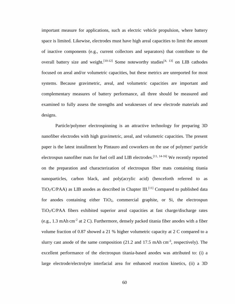
60
important measure for applications, such as electric vehicle propulsion, where battery
space is limited. Likewise, electrodes must have high areal capacities to limit the amount
of inactive components (e.g., current collectors and separators) that contribute to the
overall battery size and weight.[10-12] Some noteworthy studies[4, 13] on LIB cathodes
focused on areal and/or volumetric capacities, but these metrics are unreported for most
systems. Because gravimetric, areal, and volumetric capacities are important and
complementary measures of battery performance, all three should be measured and
examined to fully assess the strengths and weaknesses of new electrode materials and
designs.
Particle/polymer electrospinning is an attractive technology for preparing 3D
nanofiber electrodes with high gravimetric, areal, and volumetric capacities. The present
paper is the latest installment by Pintauro and coworkers on the use of polymer/ particle
electrospun nanofiber mats for fuel cell and LIB electrodes.[11, 14-16] We recently reported
on the preparation and characterization of electrospun fiber mats containing titania
nanoparticles, carbon black, and poly(acrylic acid) (henceforth referred to as
TiO2/C/PAA) as LIB anodes as described in Chapter III.[11] Compared to published data
for anodes containing either TiO2, commercial graphite, or Si, the electrospun
TiO2/C/PAA fibers exhibited superior areal capacities at fast charge/discharge rates
(e.g., 1.3 mAh cm-2 at 2 C). Furthermore, densely packed titania fiber anodes with a fiber
volume fraction of 0.87 showed a 21 % higher volumetric capacity at 2 C compared to a
slurry cast anode of the same composition (21.2 and 17.5 mAh cm-3, respectively). The
excellent performance of the electrospun titania-based anodes was attributed to: (i) a
large electrode/electrolyte interfacial area for enhanced reaction kinetics, (ii) a 3D

61
nanofiber network containing interfiber voids for good electrolyte infiltration, and
(iii) short Li+ transport pathways between the electrolyte and the active material in the
radial fiber direction.
Although the TiO2/C/PAA fiber anodes exhibited high areal and volumetric
capacities at fast charge/discharge rates, the material had a relatively low gravimetric
capacity (e.g., 70 mAh g-1 at 0.1 C) owing to the low theoretical capacity of titania
(335 mAh g-1 for LiTiO2) and the low titania content in the fibers; only 40 wt % of the
electrode was TiO2, with 25 wt % inactive carbon particles for electrical conduction. To
address these limitations, we present results for particle/polymer electrospun nanofiber
anodes containing carbon nanoparticles distributed throughout a poly(vinylidene fluoride)
(PVDF) binder. The use of carbon as an active material eliminates the need for
conductive additives and thus allows for high active material loadings in the fiber
(65 wt % vs. 40 wt % for TiO2/C/PAA). Additional advantages of carbon nanofiber
anodes over titania include the high theoretical capacity of carbon (372 mAh g-1) and a
low operating potential (0.015 – 1.5 V vs. Li/Li+, as compared to 1.0 – 2.6 V vs. Li/Li+
for titania).
Previous reports on electrospun carbon nanofiber anodes for LIBs utilized high
temperature processing to convert a polymer nanofiber mat into an electronically
conductive carbon fiber network. Zhang et al.[17] electrospun poly(acrylonitrile) (PAN)
nanofibers followed by high temperature pyrolysis to create a carbon nanofiber mat that
exhibited a high gravimetric capacity of 555 mAh g-1 at ~ 0.18 C and 260 mAh g-1 at
~ 3.6 C. Similarly, Wu et al.[18] characterized carbon nanofiber anodes prepared from
electrospun PAN, where the polymer was carbonized at different temperatures. These

62
materials exhibited moderately high capacities ranging from 250 – 450 mAh g-1 and
excellent cycle life (more than 500 cycles at 0.27 C without significant capacity fade).
Unfortunately, the volumetric capacity of such carbon fiber anodes was not discussed in
these and other published papers, but it is reasonable to assume that the fiber volume
fraction was < 0.25, which is far too low for practical battery use. As-spun polymeric
nanofiber mats typically have a fiber volume fraction in the range of 0.01 – 0.25,[19-21]
that furthers decrease after fiber pyrolysis.
Composite nanofiber electrodes prepared using particle/ polymer electrospinning
are fundamentally different from and offer several key advantages over pyrolyzed carbon
nanofiber electrodes. Whereas pyrolyzed carbon nanofibers are usually brittle and
fracture easily,[22-24] particle/polymer nanofiber mats are flexible and mechanically robust
owing to the presence of the polymer binder.[25] Thus, composite nanofiber mat
electrodes can be used in flexible battery architectures, and they can be mechanically
compacted under high pressure without fracture to increase the fiber volume fraction and
volumetric storage capacity. Particle/polymer electrospinning is also a robust platform
that can be used to prepare novel nanostructured electrodes from new active materials
and binders as they are developed. This cannot be said of pyrolyzed fiber mats, where the
primary electrode component will always be carbon. The goal of the present study was to
prepare particle/polymer nanofiber anodes with high gravimetric, areal, and volumetric
capacities at fast charge/discharge rates (e.g., ≥ 1 C) and long cycle life. High areal
capacities were achieved through the use of thick electrodes (thicknesses up to 820 µm),
and the volumetric capacity of the electrospun anodes was increased by mechanically
compacting the mats up to a fiber volume fraction of 0.80. Compared with traditional
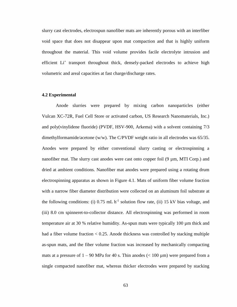
63
slurry cast electrodes, electrospun nanofiber mats are inherently porous with an interfiber
void space that does not disappear upon mat compaction and that is highly uniform
throughout the material. This void volume provides facile electrolyte intrusion and
efficient Li+ transport throughout thick, densely-packed electrodes to achieve high
volumetric and areal capacities at fast charge/discharge rates.
4.2 Experimental
Anode slurries were prepared by mixing carbon nanoparticles (either
Vulcan XC-72R, Fuel Cell Store or activated carbon, US Research Nanomaterials, Inc.)
and poly(vinylidene fluoride) (PVDF, HSV-900, Arkema) with a solvent containing 7/3
dimethylformamide/acetone (w/w). The C/PVDF weight ratio in all electrodes was 65/35.
Anodes were prepared by either conventional slurry casting or electrospinning a
nanofiber mat. The slurry cast anodes were cast onto copper foil (9 µm, MTI Corp.) and
dried at ambient conditions. Nanofiber mat anodes were prepared using a rotating drum
electrospinning apparatus as shown in Figure 4.1. Mats of uniform fiber volume fraction
with a narrow fiber diameter distribution were collected on an aluminum foil substrate at
the following conditions: (i) 0.75 mL h-1 solution flow rate, (ii) 15 kV bias voltage, and
(iii) 8.0 cm spinneret-to-collector distance. All electrospinning was performed in room
temperature air at 30 % relative humidity. As-spun mats were typically 100 µm thick and
had a fiber volume fraction < 0.25. Anode thickness was controlled by stacking multiple
as-spun mats, and the fiber volume fraction was increased by mechanically compacting
mats at a pressure of 1 – 90 MPa for 40 s. Thin anodes (< 100 µm) were prepared from a
single compacted nanofiber mat, whereas thicker electrodes were prepared by stacking

64
multiple as-spun mats followed by compaction to ensure good interfiber mat contact. The
morphologies of nanofiber and slurry cast anodes were assessed using scanning electron
microscopy (Hitachi S4200 SEM) after gold sputtering for 90 s.
To determine the active material loading in the fibers after electrospinning,
thermogravimetric analyses (TGA) were performed on Vulcan XC-72R powder, PVDF
powder, and C/PVDF nanofiber mats. Each sample was heated under nitrogen
atmosphere to 750 °C at a rate of 10 °C min-1, followed by a 4 h constant temperature
hold at 750 °C. A simple mass balance was used to determine the carbon loading in a
fiber mat, where the TGA mass loss of the C/PVDF fibers (30.5 %) was given by the sum
of mass losses for carbon and PVDF powders (3.1 and 73.5 %, respectively). The fiber
volume fraction of an electrospun mat was calculated as the ratio of the measured mat
density to the density of a hypothetical/idealized mat containing no interfiber voids. To
estimate the density of the latter, an SEM image of a reference nanofiber mat was
processed using ImageJ such that the interfiber voids were represented by white pixels
and the electrospun fibers were black pixels. The fiber volume fraction of the reference
mat was then determined as the fraction of black pixels in this image. The reference mat
was highly compacted to minimize depth of field errors when visually determining fiber
volume fraction. From the apparent fiber volume fraction and the measured density of the
reference mat, the extrapolated density of a nanofiber mat with no interfiber void space
was found to be 0.91 ± 0.03 g cm-3. From the densities of carbon black and PVDF and the
known composition of electrospun fibers, a zero porosity mat should have a density of
1.79 g cm-3. From these two density calculations, the internal porosity of an electrospun
fiber was estimated to be 0.49.
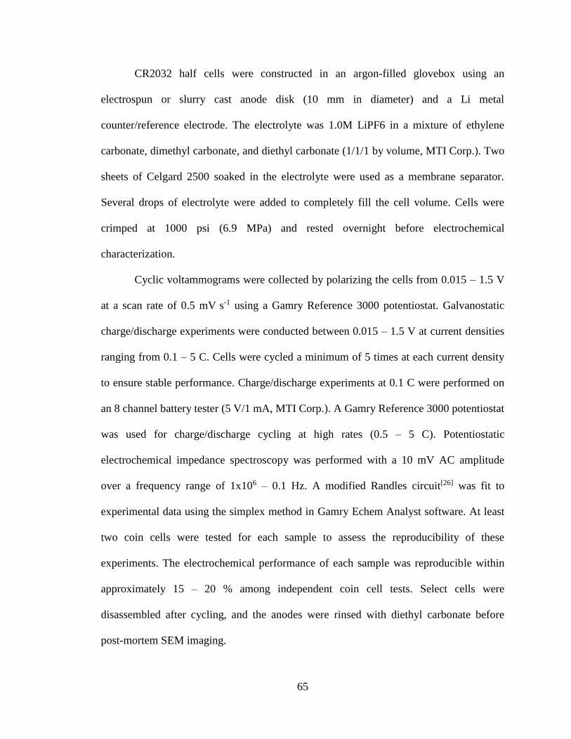
65
CR2032 half cells were constructed in an argon-filled glovebox using an
electrospun or slurry cast anode disk (10 mm in diameter) and a Li metal
counter/reference electrode. The electrolyte was 1.0M LiPF6 in a mixture of ethylene
carbonate, dimethyl carbonate, and diethyl carbonate (1/1/1 by volume, MTI Corp.). Two
sheets of Celgard 2500 soaked in the electrolyte were used as a membrane separator.
Several drops of electrolyte were added to completely fill the cell volume. Cells were
crimped at 1000 psi (6.9 MPa) and rested overnight before electrochemical
characterization.
Cyclic voltammograms were collected by polarizing the cells from 0.015 – 1.5 V
at a scan rate of 0.5 mV s-1 using a Gamry Reference 3000 potentiostat. Galvanostatic
charge/discharge experiments were conducted between 0.015 – 1.5 V at current densities
ranging from 0.1 – 5 C. Cells were cycled a minimum of 5 times at each current density
to ensure stable performance. Charge/discharge experiments at 0.1 C were performed on
an 8 channel battery tester (5 V/1 mA, MTI Corp.). A Gamry Reference 3000 potentiostat
was used for charge/discharge cycling at high rates (0.5 – 5 C). Potentiostatic
electrochemical impedance spectroscopy was performed with a 10 mV AC amplitude
over a frequency range of 1x10⁶ – 0.1 Hz. A modified Randles circuit[26] was fit to
experimental data using the simplex method in Gamry Echem Analyst software. At least
two coin cells were tested for each sample to assess the reproducibility of these
experiments. The electrochemical performance of each sample was reproducible within
approximately 15 – 20 % among independent coin cell tests. Select cells were
disassembled after cycling, and the anodes were rinsed with diethyl carbonate before
post-mortem SEM imaging.
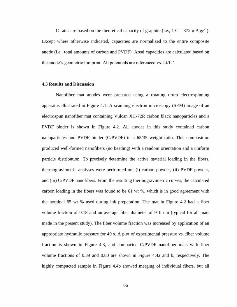
66
C-rates are based on the theoretical capacity of graphite (i.e., 1 C = 372 mA gC-1).
Except where otherwise indicated, capacities are normalized to the entire composite
anode (i.e., total amounts of carbon and PVDF). Areal capacities are calculated based on
the anode’s geometric footprint. All potentials are referenced vs. Li/Li+.
4.3 Results and Discussion
Nanofiber mat anodes were prepared using a rotating drum electrospinning
apparatus illustrated in Figure 4.1. A scanning electron microscopy (SEM) image of an
electrospun nanofiber mat containing Vulcan XC-72R carbon black nanoparticles and a
PVDF binder is shown in Figure 4.2. All anodes in this study contained carbon
nanoparticles and PVDF binder (C/PVDF) in a 65/35 weight ratio. This composition
produced well-formed nanofibers (no beading) with a random orientation and a uniform
particle distribution. To precisely determine the active material loading in the fibers,
thermogravimetric analyses were performed on: (i) carbon powder, (ii) PVDF powder,
and (iii) C/PVDF nanofibers. From the resulting thermogravimetric curves, the calculated
carbon loading in the fibers was found to be 61 wt %, which is in good agreement with
the nominal 65 wt % used during ink preparation. The mat in Figure 4.2 had a fiber
volume fraction of 0.18 and an average fiber diameter of 910 nm (typical for all mats
made in the present study). The fiber volume fraction was increased by application of an
appropriate hydraulic pressure for 40 s. A plot of experimental pressure vs. fiber volume
fraction is shown in Figure 4.3, and compacted C/PVDF nanofiber mats with fiber
volume fractions of 0.39 and 0.80 are shown in Figure 4.4a and b, respectively. The
highly compacted sample in Figure 4.4b showed merging of individual fibers, but all
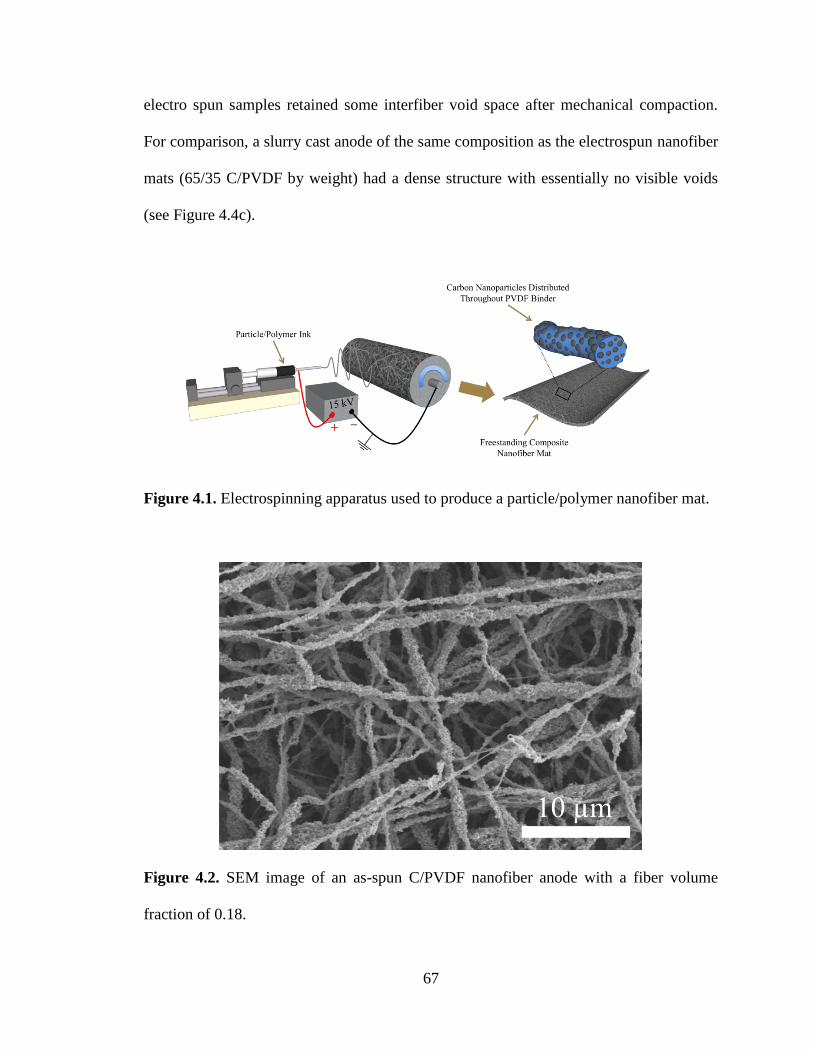
67
electro spun samples retained some interfiber void space after mechanical compaction.
For comparison, a slurry cast anode of the same composition as the electrospun nanofiber
mats (65/35 C/PVDF by weight) had a dense structure with essentially no visible voids
(see Figure 4.4c).
Figure 4.1. Electrospinning apparatus used to produce a particle/polymer nanofiber mat.
Figure 4.2. SEM image of an as-spun C/PVDF nanofiber anode with a fiber volume
fraction of 0.18.
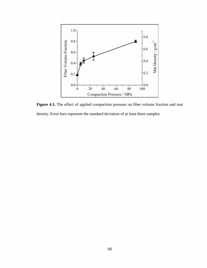
68
Figure 4.3. The effect of applied compaction pressure on fiber volume fraction and mat
density. Error bars represent the standard deviation of at least three samples.

69
Figure 4.4. SEM images of electrospun C/PVDF nanofiber anodes with fiber volume
fractions of (a) 0.39 and (b) 0.80 and (c) a slurry cast C/PVDF anode.
Cyclic voltammograms of a C/PVDF nanofiber anode are shown in Figure 4.5a.
During initial scans, slight peak shifting occurred, but the voltammograms stabilized after
15 cycles with no changes during subsequent scans. A sloping baseline with a small peak
(0.8 V) during lithiation and two broad peaks (0.3 and 1.0 V) during delithiation can be

70
seen, which is consistent with Takei et al.[27] who characterized carbon black anodes.
Integrating the forward and reverse scans yields a coulombic efficiency of 98.0 %, which
indicates good chemical reversibility of the lithiation reaction. Similar voltammograms
were observed for electrospun anodes with fiber volume fractions ranging from
0.18 – 0.80 and for a slurry cast C/PVDF anode. The sloping baselines in the
voltammograms of Figure 4.5a could be the result of a bulky electrical double layer at the
electrode’s surface. To determine the double layer capacitance of the nanofiber anodes, a
Nyquist plot was generated through an electrochemical impedance experiment, and the
results were fitted with a modified Randles circuit,[26] as shown in Figure 4.5b. The
calculated double-layer capacitance was 4.8 mF, which is a typical value for LIB
anodes.[28, 29] This result shows that no bulky electrical double layer is present, and the
nanofiber anodes undergo electrochemical lithiation/ delithiation as expected.
The charge/discharge curves shown in Figure 4.6a provide further insights into
the fundamental electrochemical characteristics of C/PVDF nanofiber anodes. The
sloping profiles over 0.015 – 1.5 V indicate that lithiation/delithiation processes occurred
over a wide potential range compared to graphite (typically < 0.5 V vs. Li/Li+). Sloping
charge/discharge curves for nongraphitized carbon anodes were reported by several
groups[30-38] and are attributed to a distribution of site energies in the active material.[39]
For the electrospun anodes, the shapes of the charge and discharge curves did not change
with fiber volume fractions in the 0.18 – 0.80 range. These curves also match those
reported by Tran et al.[40] who characterized several slurry cast carbon black anodes. At
0.1 C, the gravimetric capacity of the nanofiber anodes was 166 mAh g-1, which
corresponds to a carbon active material capacity of 255 mAh g-1. This value is within the

71
range of capacities for various carbon blacks reported in the literature
(197 – 346 mAh g-1)[40, 41] and is similar to but a bit lower than that achieved with carbon
fiber anodes (e.g., ~ 290 mAh g-1 for a pyrolyzed electrospun PAN mat[17] when cycled
between 0 – 1.5 V at ~ 0.18 C and ~ 200 mAh g-1 for a carbon fiber anode grown by
chemical vapor deposition).[42] As expected, at higher charge/discharge rates, the
C/PVDF nanofiber anode capacity decreased with greater separation between the
lithiation and delithiation curves, owing to a combination of activation, ohmic, and
concentration overpotentials within the cell.[43] Figure 4.6b shows the capacity is stable at
charge/discharge rates up to 5 C.
Figure 4.6c shows the long-term performance of a C/PVDF nanofiber anode over
several hundred cycles at 0.1 C. A low first cycle coulombic efficiency (30.3 %) is
attributed to the formation of a solid-electrolyte interface (SEI) layer. Similar irreversible
capacity losses for carbon black anodes were reported by several groups.[41, 44, 45] Despite
this initial loss, the nanofiber anode had improved efficiencies during subsequent cycles
(e.g., during the 2nd, 10th, and 50th cycle, the coulombic efficiencies were 82.1, 96.3, and
99.4 %, respectively). The anode also exhibited outstanding electrochemical stability
with 91.7 % capacity retention after 510 cycles at 0.1 C. Likewise, the nanofiber structure
was physically stable in a battery environment; initial and post-mortem SEM images of
an electrospun anode are shown in Figures 4.7a and 4.7b, respectively. Although an SEI
layer was deposited on the fibers, the interfiber voids were wellmaintained during
cycling.

72
Figure 4.5. Electrochemical characterization of C/PVDF nanofiber anodes. (a) Cyclic
voltammograms collected at a scan rate of 0.5 mV s-1 and (b) Nyquist plot showing
experimental data and the fit for an equivalent circuit model.[26]

73
Figure 4.6. Electrochemical characterization of C/PVDF nanofiber anodes. (a)
Charge/discharge curves at current densities corresponding to 0.1 – 5 C, (b) cycling
stability at 0.1 – 5 C, and (c) long-term performance over 510 cycles at 0.1 C.

74
Figure 4.7. SEM images of a C/PVDF nanofiber anode containing a fiber volume
fraction of 0.25 (a) before cycling and (b) after 510 cycles at 0.1 C.
Electrode performance metrics based on the electrode footprint and volume are
underemphasized in the literature despite their importance for practical battery
applications. Thus, a primary motivation of the current study was to evaluate how anode
thickness and fiber volume fraction of a nanofiber mat affect performance. Figure 4.8a
shows the dependence of volumetric capacity at 0.1 C on fiber volume fraction for five
electrospun C/PVDF anodes. Nanofiber mats with a fiber volume fraction of 0.25
exhibited a very low volumetric capacity of 36 mAh cm-3 owing to the large interfiber
void space. Volumetric capacity increased linearly with fiber volume fraction, which
indicates that active material utilization was similar for all electrodes at a low
charge/discharge rate. A highly compacted mat with a fiber volume fraction of 0.79 had a
high volumetric capacity of 102 mAh cm-3 at 0.1 C, which is considerably higher than
that of a slurry cast anode of the same composition (79 mAh cm-3).
Figure 4.8b shows the effect of charge/discharge rate on the volumetric capacity
of: (i) electrospun C/PVDF mats with a fiber volume fraction of 0.34. 0.61, or 0.79; (ii) a
slurry cast C/PVDF anode of the same composition (shown in Figure 4.4c); and (iii) a

75
slurry cast graphite anode reported by Sivakkumar et al.[46] where the graphite particle
size is larger than the carbon particles used in the present study (31 µm vs. 40 nm). The
effect of fiber volume fraction on volumetric capacity is pronounced for nanofiber mats,
up to a charge/discharge rate of ~ 2 C. The volumetric capacity at 2 C of a nanofiber
electrode with a fiber volume fraction of 0.79 (55 mAh cm-3) was twice that of the
graphite anode and 67 % higher than that of the C/ PVDF slurry cast anode. As shown in
Figure 4.8c, a highly compacted nanofiber anode also had excellent cycling stability, with
94 % capacity retention over 100 cycles at 2 C. The sharp peak around cycle 50 was
caused by temporarily removing the cell from the battery tester. The excellent
performance of C/ PVDF nanofiber anodes is attributed to the presence of intraand
interfiber voids, which allow for electrolyte penetration and efficient Li+ transport
throughout the 3D fiber mat. Compared to conventional slurry cast anodes, the
electrospun nanofiber anodes contain short Li+ transport pathways from the liquid
electrolyte to the carbon nanoparticles in the radial fiber direction.
In addition to high volumetric capacity, anodes must have high areal capacities at
fast charge/discharge rates. Thick electrodes with high areal capacities are desired to
reduce the amount of inactive components in a full cell (e.g., current collectors,
separators, etc.). Figure 4.8d shows the areal capacity at charge/discharge rates up to 5 C
for: (i) electrospun anodes with a fiber volume fraction of 0.34, 0.61, or 0.79 (thicknesses
of 340, 190, and 140 µm, respectively); (ii) a slurry cast C/PVDF anode of the same
composition (200 µm); and (iii) a slurry cast graphite anode reported by
Sivakkumar et al.[46] (100 µm). All electrodes were prepared such that they had areal
capacities of ~ 1.5 mAh cm-2 at 0.1 C. Nanofiber mats with fiber volume fractions of 0.61

76
and 0.79 exhibited similar areal capacities of 0.77 and 0.79 mAh cm-2 at 2 C. The
electrospun anode with a fiber volume fraction of 0.34 had the best rate capabilities of all
samples tested, with a reversible capacity of 1.12 mAh cm-2 at 2 C. In comparison, the
slurry cast C/PVDF and graphite anodes had significantly lower capacities at 2 C
(0.67 and 0.27 mAh cm-2, respectively).
Figure 4.8. (a) Volumetric capacity at 0.1 C as a function of fiber volume fraction in the
anode, (b) volumetric capacity at charge/discharge rates up to 5 C for electrospun and
slurry cast anodes, (c) cycling stability at 2 C for a C/PVDF nanofiber anode, and
(d) Areal capacity at charge/discharge rates (C-rate) up to 5 C for nanofiber and slurry
cast anodes. φfiber refers to fiber volume fraction in (b) – (d).
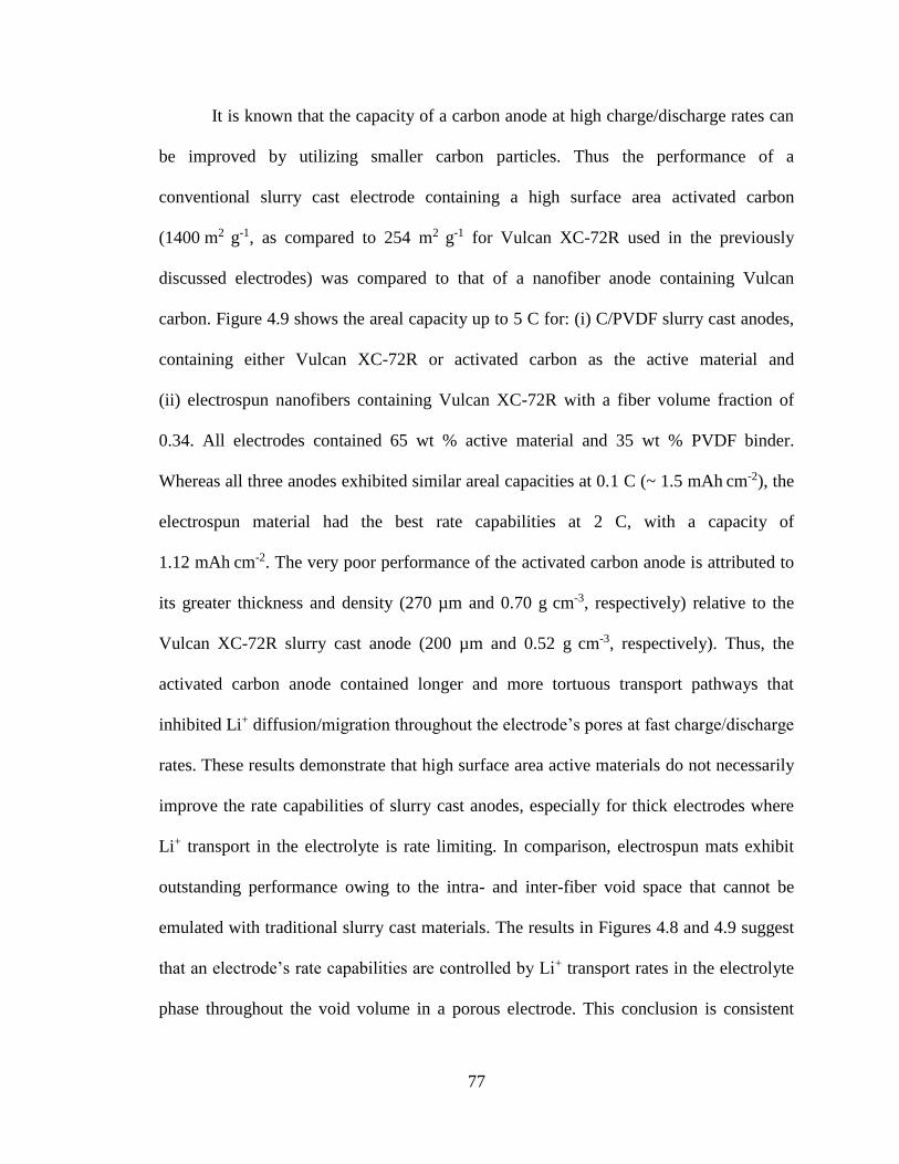
77
It is known that the capacity of a carbon anode at high charge/discharge rates can
be improved by utilizing smaller carbon particles. Thus the performance of a
conventional slurry cast electrode containing a high surface area activated carbon
(1400 m2 g-1, as compared to 254 m2 g-1 for Vulcan XC-72R used in the previously
discussed electrodes) was compared to that of a nanofiber anode containing Vulcan
carbon. Figure 4.9 shows the areal capacity up to 5 C for: (i) C/PVDF slurry cast anodes,
containing either Vulcan XC-72R or activated carbon as the active material and
(ii) electrospun nanofibers containing Vulcan XC-72R with a fiber volume fraction of
0.34. All electrodes contained 65 wt % active material and 35 wt % PVDF binder.
Whereas all three anodes exhibited similar areal capacities at 0.1 C (~ 1.5 mAh cm-2), the
electrospun material had the best rate capabilities at 2 C, with a capacity of
1.12 mAh cm-2. The very poor performance of the activated carbon anode is attributed to
its greater thickness and density (270 µm and 0.70 g cm-3, respectively) relative to the
Vulcan XC-72R slurry cast anode (200 µm and 0.52 g cm-3, respectively). Thus, the
activated carbon anode contained longer and more tortuous transport pathways that
inhibited Li+ diffusion/migration throughout the electrode’s pores at fast charge/discharge
rates. These results demonstrate that high surface area active materials do not necessarily
improve the rate capabilities of slurry cast anodes, especially for thick electrodes where
Li+ transport in the electrolyte is rate limiting. In comparison, electrospun mats exhibit
outstanding performance owing to the intra- and inter-fiber void space that cannot be
emulated with traditional slurry cast materials. The results in Figures 4.8 and 4.9 suggest
that an electrode’s rate capabilities are controlled by Li+ transport rates in the electrolyte
phase throughout the void volume in a porous electrode. This conclusion is consistent
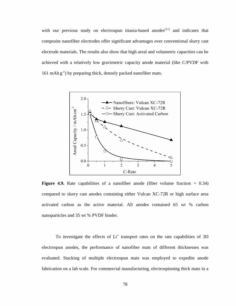
78
with our previous study on electrospun titania-based anodes[11] and indicates that
composite nanofiber electrodes offer significant advantages over conventional slurry cast
electrode materials. The results also show that high areal and volumetric capacities can be
achieved with a relatively low gravimetric capacity anode material (like C/PVDF with
161 mAh g-1) by preparing thick, densely packed nanofiber mats.
Figure 4.9. Rate capabilities of a nanofiber anode (fiber volume fraction = 0.34)
compared to slurry cast anodes containing either Vulcan XC-72R or high surface area
activated carbon as the active material. All anodes contained 65 wt % carbon
nanoparticles and 35 wt % PVDF binder.
To investigate the effects of Li+ transport rates on the rate capabilities of 3D
electrospun anodes, the performance of nanofiber mats of different thicknesses was
evaluated. Stacking of multiple electrospun mats was employed to expedite anode
fabrication on a lab scale. For commercial manufacturing, electrospinning thick mats in a

79
single step using a roll-to-roll process might be more desirable (and cost effective), but
the electrode performance of the two systems should be identical for a given mat
thickness and fiber volume fraction. Four electrospun anodes each with a fiber volume
fraction ~ 0.60 and a thickness ranging from 40 – 510 µm were characterized. Figure
4.10a shows that areal capacity at 0.1 C scaled linearly with anode thickness, indicating
similar active material utilization for all samples at slow charge/discharge rates. The
thicker electrodes, however, had lower capacities at high charge/discharge rates (as
shown in Figure 4.10b, where the areal capacity of a 510 µm anode at 2 C was only 0.17
mAh cm-2 vs. 0.77 mAh cm-2 for a 190 µm anode). The lower capacity of the thick
electrodes at fast charge/discharge rates is attributed to slower Li+ ion transport, where
Li+ transport to the back of the anode (at points farthest from the separator) is rate
limiting, even for nanofiber anodes with an interfiber void fraction of 0.40. Thus, Li+ ions
do not have adequate time to reach all active material sites before the cutoff potential is
reached, resulting in lower active material utilization for thicker electrodes.[11, 12] This
conclusion is consistent with a report by Fongy et al.[13] who studied the effects of
electrode thickness and porosity on the rate capabilities of LiFePO4 cathodes. One must
consider both fiber mat thickness and fiber volume fraction when optimizing areal
capacity at fast charge/ discharge rates. To prove this point, two thick electrospun anodes
with different fiber volume fractions were prepared and characterized. In these
experiments, the fiber volume fraction was either 0.42 or 0.63, and the thickness was
either 820 or 510 µm, respectively. Note that the more porous anode had to be made
thicker to achieve the same carbon loading. As shown in Figure 4.10c, both anodes had
similar areal capacities at 0.1 C (~ 4 mAh cm-2), but the more porous nanofiber anode had

80
higher capacities at charge/discharge rates ≥ 0.5 C. At 2 C, the areal capacity of the anode
with a fiber volume fraction of 0.42 was 4-times greater than that of the anode with a
fiber volume fraction of 0.63 (0.70 vs. 0.17 mAh cm-2).

81
Figure 4.10. (a) Areal capacity at 0.1 C as a function of anode thickness for electrospun
anodes containing fiber volume fractions of 0.59 – 0.66, (b) rate capabilities of
electrospun anodes containing fiber volume fractions of 0.59 – 0.66 and thicknesses up to
510 µm, and (c) rate capabilities of thick electrospun anodes containing fiber volume
fractions (φfiber) of 0.42 and 0.63 and thicknesses of 820 and 510 µm, respectively.

82
4.4 Conclusions
Particle/polymer electrospinning is used to prepare high performance anodes
containing carbon nanoparticles and a poly(vinylidene fluoride) binder (C/PVDF) for
LIBs. By utilizing electronically conductive carbon nanoparticles as the Li host, high
active material loadings (65 wt %) and high gravimetric capacities
(161 mAh g-1 at 0.1 C, 1 C = 372 mA gC-1) were achieved. The nanofiber anodes
exhibited excellent electrochemical stability with 91.7 % capacity retention after
510 cycles at 0.1 C. Furthermore, the nanofiber morphology was structurally stable
during charge/discharge processes, and the interfiber voids were well-maintained during
cycling.
Whereas anodes produced using many nanofabrication schemes (e.g., nanowires,
carbon nanofibers, etc.) are restricted to low areal and/or volumetric capacities,
particle/polymer electrospinning does not have these limitations. Mechanical compaction
was used to increase the fiber volume fraction and volumetric capacity of the nanofiber
mats. At a 0.1 C charge/discharge rate, a highly densified nanofiber mat with a fiber
volume fraction of 0.79 exhibited a volumetric capacity of 102 mAh cm-3. Furthermore,
highly compacted electrospun anodes had excellent rate capabilities with a stable
volumetric capacity of 55 mAh cm-3 at 2 C which is 67 % greater than that of a slurry cast
C/PVDF anode (33 mAh cm-3) and twice that of a graphite anode (27 mAh cm-3).
Particle/polymer electrospinning was also used to prepare thick anodes with high
areal capacities, up to 4.3 mAh cm-2 at 0.1 C. The rate capabilities of thick electrodes
were significantly improved by increasing the interfiber void volume in the nanofiber
mat. An anode containing a fiber volume fraction of 0.42 had a 4-fold higher areal
83
capacity at 2 C as compared to an anode mat with a volume fraction of 0.63
(0.70 and 0.17 mAh cm-2, respectively).
Particle/polymer electrospinning is a robust platform for the preparation of high
performance LIB anodes with high gravimetric, volumetric, and areal capacities. The
method can accommodate new active materials and polymer binders as they are
developed. The excellent performance of the C/PVDF nanofiber anodes is attributed to
the intra- and interfiber void space, which allows for good electrolyte uptake and efficient
Li+ transport from the electrolyte to active material nanoparticles in the radial fiber
direction. The results show that proper electrode design on the micron-scale level can
enhance Li+ transport rates and improve the performance of a LIB.
84
4.5 References
[1] P. N. Pintauro, Polym. Rev. 2015, 55, 201.
[2] M. Armand, J.-M. Tarascon, Nature 2008, 451, 652.
[3] G. Liu, H. Zheng, A. S. Simens, A. M. Minor, X. Song, V. S. Battaglia, J.
Electrochem. Soc. 2007, 154, A1129.
[4] S. K. Martha, J. O. Kiggans, J. Nanda, N. J. Dudney, J. Electrochem. Soc. 2011,
158, A1060.
[5] X.-L. Huang, R.-Z. Wang, D. Xu, Z.-L. Wang, H.-G. Wang, J.-J. Xu, Z. Wu, Q.-
C. Liu, Y. Zhang, X.-B. Zhang, Adv. Funct. Mater. 2013, 23, 4345.
[6] H.-G. Wang, S. Yuan, D.-L. Ma, X.-B. Zhang, J.-M. Yan, Energy Environ. Sci.
2015, 8, 1660.
[7] X. L. Huang, D. Xu, S. Yuan, D. L. Ma, S. Wang, H. Y. Zheng, X. B. Zhang,
Adv. Mater. 2014, 26, 7264.
[8] H. G. Wang, D. L. Ma, Y. Huang, X. B. Zhang, Chem. Eur. J. 2012, 18, 8987.
[9] S. Yuan, X. L. Huang, D. L. Ma, H. G. Wang, F. Z. Meng, X. B. Zhang, Adv.
Mater. 2014, 26, 2273.
[10] N. Nitta, G. Yushin, Part. Part. Syst. Char. 2014, 31, 317.
[11] E. C. Self, R. Wycisk, P. N. Pintauro, J. Power Sources 2015, 282, 187.
[12] M. Singh, J. Kaiser, H. Hahn, J. Electrochem. Soc. 2015, 162, A1196.
[13] C. Fongy, A. C. Gaillot, S. Jouanneau, D. Guyomard, B. Lestriez, J. Electrochem.
Soc. 2010, 157, A885.
[14] W. Zhang, P. N. Pintauro, ChemSusChem 2011, 4, 1753.
[15] M. Brodt, R. Wycisk, P. N. Pintauro, J. Electrochem. Soc. 2013, 160, F744.
[16] M. Brodt, T. Han, N. Dale, E. Niangar, R. Wycisk, P. Pintauro, J. Electrochem.
Soc. 2014, 162, F84.
[17] B. Zhang, Y. Yu, Z.-L. Xu, S. Abouali, M. Akbari, Y.-B. He, F. Kang, J.-K. Kim,
Adv. Energy Mater. 2014, 4, 1301448.
[18] Y. Wu, M. V. Reddy, B. V. Chowdari, S. Ramakrishna, ACS Appl. Mater.
Interfaces 2013, 5, 12175.
[19] X.-H. Qin, D.-P. Xin, Fiber Polym. 2010, 11, 632.
[20] H. Hou, D. H. Reneker, Adv. Mater. 2004, 16, 69.
[21] A. Park, F. Turley, R. Wycisk, P. Pintauro, J. Electrochem. Soc. 2015, 162, F560.
[22] E. Zussman, X. Chen, W. Ding, L. Calabri, D. A. Dikin, J. P. Quintana, R. S.
Ruoff, Carbon 2005, 43, 2175.
[23] S. N. Arshad, M. Naraghi, I. Chasiotis, Carbon 2011, 49, 1710.
[24] M. Faccini, G. Borja, M. Boerrigter, D. Morillo Martín, S. Martìnez Crespiera, S.
Vázquez-Campos, L. Aubouy, D. Amantia, J. Nanomater. 2015, 2015, 1.
[25] S. H. Kim, S. Y. Jeon, P. J. Yoo, L. S. Pu, J. Y. Lee, Fiber Polym. 2014, 14, 1975.
[26] J. Bisquert, G. Garcia-Belmonte, P. Bueno, E. Longo, L. O. S. Bulhões, J.
Electroanal. Chem. 1998, 452, 229.
[27] K. Takei, N. Terada, K. Kuma, T. Iwahori, T. Uwai, T. Miura, J. Power Sources
1995, 55, 191.
[28] L. Li, A. R. Raji, J. M. Tour, Adv. Mater. 2013, 25, 6298.
[29] M. V. Reddy, G. Prithvi, K. P. Loh, B. V. Chowdari, ACS Appl. Mater. Interfaces
2014, 6, 680.

85
[30] L. Ji, Y. Yao, O. Toprakci, Z. Lin, Y. Liang, Q. Shi, A. J. Medford, C. R. Millns,
X. Zhang, J. Power Sources 2010, 195, 2050.
[31] X.-B. Cheng, Q. Zhang, H.-F. Wang, G.-L. Tian, J.-Q. Huang, H.-J. Peng, M.-Q.
Zhao, F. Wei, Catal. Today 2015, 249, 244.
[32] M. Kim, D. Y. Kim, Y. Kang, O. O. Park, RSC Adv. 2015, 5, 3299.
[33] R. Mei, X. Song, Y. Hu, Y. Yang, J. Zhang, Electrochim. Acta 2015, 153, 540.
[34] S. Petnikota, N. K. Rotte, M. V. Reddy, V. V. Srikanth, B. V. Chowdari, ACS
Appl. Mater. Interfaces 2015, 7, 2301.
[35] K. R. Saravanan, N. Kalaiselvi, Carbon 2015, 81, 43.
[36] Z. Sun, X. Song, P. Zhang, L. Gao, RSC Adv. 2015, 5, 3657.
[37] S. Wang, Y. Xing, C. Xiao, X. Wei, H. Xu, S. Zhang, RSC Adv. 2015, 5, 7959.
[38] H. Zhang, X. Sun, X. Zhang, H. Lin, K. Wang, Y. Ma, J. Alloys Compd. 2015,
622, 783.
[39] J. R. Dahn, R. Fong, M. J. Spoon, Phys. Rev. B 1990, 42, 6424.
[40] T. D. Tran, J. H. Feikert, J. Electrochem. Soc. 1995, 142, 3297.
[41] D. Molina Piper, S.-B. Son, J. J. Travis, Y. Lee, S. S. Han, S. C. Kim, K. H. Oh,
S. M. George, S.-H. Lee, C. Ban, J. Power Sources 2015, 275, 605.
[42] H. Kim, X. Huang, X. Guo, Z. Wen, S. Cui, J. Chen, ACS Appl. Mater. Interfaces
2014, 6, 18590.
[43] D. Danilov, R. A. H. Niessen, P. H. L. Notten, J. Electrochem. Soc. 2011, 158,
A215.
[44] L. Fransson, T. Eriksson, K. Edström, T. Gustafsson, J. O. Thomas, J. Power
Sources 2001, 101, 1.
[45] F. La Mantia, R. A. Huggins, Y. Cui, J. Appl. Electrochem. 2012, 43, 1.
[46] S. R. Sivakkumar, J. Y. Nerkar, A. G. Pandolfo, Electrochim. Acta 2010, 55,
3330.

86
CHAPTER V
LICOO2-BASED FIBER CATHODES FOR ELECTROSPUN FULL CELL LI-ION
BATTERIES
Adapted from E. C. Self, E. C. McRen, R. Wycisk, P. N. Pintauro, Electrochim. Acta
2016, 214, 139 with permission from Elsevier.
5.1 Introduction
Despite their extraordinary commercial success, Li-ion batteries (LIBs) do not
meet the performance expectations of many end users, especially when these batteries
limit the functionality of portable electronic devices and electric vehicle propulsion
systems.[1-3] New electrode materials and designs must be developed to produce LIBs that
can be recharged quickly while providing high energy density and long cycle life. To this
end, researchers have largely focused their efforts on developing battery electrodes with
high gravimetric capacity, but such studies often miss an important point that an
electrode’s areal and volumetric capacities at high C-rates are critical for most practical
battery applications. Normalizing electrode performance only with respect to mass
conceals important limitations when thin electrodes with low densities of active material
are utilized.
Electrodes with high areal capacities are desired to increase the ratio of active
material to inactive components (e.g., current collectors, separators, etc.) in a cell;
similarly, high volumetric capacities allow batteries of a given size to store more

87
energy.[4-7] High areal and volumetric capacities can be achieved at slow charge/discharge
rates with thick, highly densified slurry cast electrodes, but such electrodes often exhibit
poor performance at high C-rates due to Li+ transport limitations in the electrode depth
direction.[8-11] To fully assess the applicability of new LIB electrode materials for
practical devices, gravimetric, areal, and volumetric capacities must all be evaluated at
both slow and fast charge/discharge rates.
The present manuscript represents the latest installment by Pintauro and
coworkers on the use of electrospun particle/polymer nanofiber mat electrodes for fuel
cells and batteries.[6, 7, 12-14] We previously reported on the preparation and
characterization of two fiber mat LIB anodes containing either: (i) titania nanoparticles,
carbon powder, and poly(acrylic acid) (TiO2/C/PAA)[6] (Chapter III) or (ii) carbon
powder and poly(vinylidene fluoride) (C/PVDF)[7] (Chapter IV). These studies showed
that thick nanofiber electrodes with a high fiber volume fraction (defined as the ratio of
the measured mat density to the density of a mat containing no interfiber voids) could be
prepared with high areal and volumetric capacities at fast charge/discharge rates, where
the capacity was stable over several hundred cycles. For example, a 1.0 mm thick
TiO2/C/PAA anode exhibited an areal capacity of 1.3 mAh cm-2 at 2 C. Likewise, a
C/PVDF anode exhibited a stable volumetric capacity of 55 mAh cm-3 at 2 C, which is
twice that of a conventional slurry cast graphite anode.[15] The excellent performance of
the electrospun fiber mats is attributed to: (i) a large electrode/electrolyte interfacial area,
(ii) short Li+ transport pathways between the electrolyte and active material in the radial
fiber direction, and (iii) good electrolyte infiltration throughout the intra- and interfiber
void space of the fiber mat. Our published work on electrospun particle/polymer battery
88
electrodes has thus far focused on the anode[6, 7], whereas the present paper deals with an
electrospun fiber mat cathode containing LiCoO2 and carbon powder in a
poly(vinylidene fluoride) (PVDF) binder.
Slurry cast LiCoO2 cathodes are widely used in commercial LIBs due to their
high energy density and good cycle life.[1, 16] Electrospun cathodes with a carefully
engineered void space (i.e., intra- and interfiber porosity) could improve LiCoO2 cathode
performance in the same way a fiber morphology improved carbon and titania-based
anodes, especially at high C-rates where performance is limited by Li+ transport.[16, 17]
Several groups[18-23] have reported on the use of electrospun LiCoO2 cathodes where the
fibers were prepared through sol-gel chemistry and high temperature pyrolysis. The
LiCoO2 nanofiber cathodes were tested as either freestanding nanofiber mats[18-21] or in
slurry cast electrodes[22, 23] containing a mixture of LiCoO2 nanofibers, carbon powder,
and polymer binder. In general, the performance of these LiCoO2 nanofiber cathodes in
LIB half cells was very good, with reversible capacities of
127 – 182 mAh g-1 at low C-rates (e.g., 0.07 – 0.25 C) and 85 – 108 mAh g-1 at high
C-rates (1.5 – 10 C). The areal and volumetric capacities of these cathodes were not
discussed, but scanning electron microscopy (SEM) images showed the electrospun mats
had very low fiber volume fractions (< 0.25), suggesting that freestanding fiber mat
electrodes had low volumetric energy densities.
In the present paper, we improve upon the performance of previous work on
electrospun and slurry cast LiCoO2 cathodes by utilizing a particle/polymer electrospun
fiber mat cathode which contains: (i) a high loading of LiCoO2 nanoparticles, (ii) carbon
powder for electrical conduction, and (iii) a PVDF binder. The polymer binder is retained
89
in the fibers after electrode fabrication which allows the mats to be compacted to high
fiber volume fractions. The binder also absorbs some electrolyte which provides fast Li+
transport in the radial fiber direction. The LiCoO2/C/PVDF nanofiber cathodes were
characterized in half cells using a Li metal counter/reference electrode and in full cells
containing an electrospun nanofiber anode prepared with carbon powder and PVDF. The
full cell results represent the first ever use of a paired electrospun particle/polymer
cathode and anode in a LIB.
5.2 Experimental
LiCoO2 nanoparticles were synthesized from a Co3O4 nanoparticle precursor
using a sonochemical method adapted from the literature.[24, 25] A dispersion containing
Co3O4 nanoparticles (10 – 50 nm, US Research Nanomaterials, Inc.) and LiOH⋅H2O
(Sigma-Aldrich) in methanol was prepared, where the Co3O4/LiOH molar ratio was 1/20
and the total solids content was 15 wt %. A Co3O4/LiOH molar ratio of 1/20 was used to
ensure complete conversion of Co3O4 to LiCoO2. The dispersion was stirred for 10 min
followed by sonication for 60 minutes. Co3O4/LiOH particles were collected by
centrifugation and then heated in air for 3 h at 700 °C to form LiCoO2 nanoparticles via a
solid-state reaction. After heating, the LiCoO2 nanoparticles were washed several times
with deionized water and methanol. Co3O4 and LiCoO2 particle size was assessed using
transmission electron microscopy (FEI Tecnai Osiris TEM). The crystal structure of
Co3O4 and LiCoO2 nanoparticles was determined by x-ray diffraction (XRD, Scintag
XGEN-4000) and Raman spectroscopy (Renishaw inVia Raman microscope with a

90
532 nm wavelength laser source). Rietveld refinement[26] of the XRD pattern for LiCoO2
was performed with FullProf Suite software[27] using a least squares fitting model.
Cathode inks were prepared by mixing the LiCoO2 nanoparticles with carbon
black (Vulcan XC-72R, Fuel Cell Store) and poly(vinylidene fluoride)
(PVDF, HSV-900, Arkema Inc.) in a solvent containing 7/3 dimethylformamide/acetone
(w/w). The ratio of LiCoO2/C/PVDF in the cathodes was fixed at 70/10/20 unless
otherwise indicated. Cathodes were prepared by either conventional slurry casting or
electrospinning a fiber mat. The slurry cast cathodes were cast onto aluminum foil and
dried at ambient conditions. Fiber mat cathodes were prepared using a single needle
spinneret and the custom rotating drum electrospinning apparatus described in
Chapter IV.[7] Mats were spun onto an aluminum foil substrate at the following
conditions: (i) 0.75 mL h-1 solution flow rate, (ii) 15 kV bias voltage, (iii) 8.0 cm
spinneret-to-collector distance, and (iv) 60 – 75 % relative humidity. The morphologies
of electrospun and slurry cast cathodes were assessed using scanning electron microscopy
(Hitachi S4200 SEM) after gold sputtering for 90 s.
Thick, densely packed LiCoO2/C/PVDF fiber mat cathodes were prepared by
stacking multiple as-spun mats followed by mechanically compacting the mats on a
hydraulic press at a pressure of 1 – 20 MPa for 40 s. The fiber volume fraction of an
electrospun mat was calculated as the ratio of the measured mat density to the density of
a hypothetical mat containing no interfiber voids. The density of the latter was
determined to be 1.71 0.02 g cm-3 based on analysis of SEM images as described in
Chapter IV.[7] This experimentally determined density is lower than the theoretical
density of a zero porosity mat (3.25 g cm-3) which was calculated using the fiber
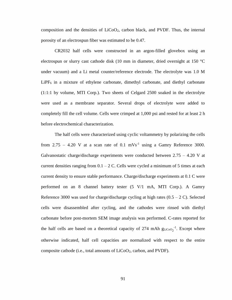
91
composition and the densities of LiCoO2, carbon black, and PVDF. Thus, the internal
porosity of an electrospun fiber was estimated to be 0.47.
CR2032 half cells were constructed in an argon-filled glovebox using an
electrospun or slurry cast cathode disk (10 mm in diameter, dried overnight at 150 °C
under vacuum) and a Li metal counter/reference electrode. The electrolyte was 1.0 M
LiPF6 in a mixture of ethylene carbonate, dimethyl carbonate, and diethyl carbonate
(1:1:1 by volume, MTI Corp.). Two sheets of Celgard 2500 soaked in the electrolyte
were used as a membrane separator. Several drops of electrolyte were added to
completely fill the cell volume. Cells were crimped at 1,000 psi and rested for at least 2 h
before electrochemical characterization.
The half cells were characterized using cyclic voltammetry by polarizing the cells
from 2.75 – 4.20 V at a scan rate of 0.1 mVs-1 using a Gamry Reference 3000.
Galvanostatic charge/discharge experiments were conducted between 2.75 – 4.20 V at
current densities ranging from 0.1 – 2 C. Cells were cycled a minimum of 5 times at each
current density to ensure stable performance. Charge/discharge experiments at 0.1 C were
performed on an 8 channel battery tester (5 V/1 mA, MTI Corp.). A Gamry
Reference 3000 was used for charge/discharge cycling at high rates (0.5 – 2 C). Selected
cells were disassembled after cycling, and the cathodes were rinsed with diethyl
carbonate before post-mortem SEM image analysis was performed. C-rates reported for
the half cells are based on a theoretical capacity of 274 mAh gLiCoO2-1. Except where
otherwise indicated, half cell capacities are normalized with respect to the entire
composite cathode (i.e., total amounts of LiCoO2, carbon, and PVDF).
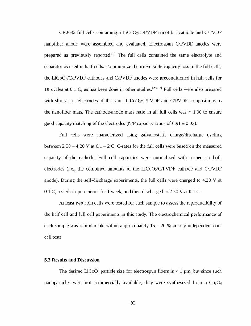
92
CR2032 full cells containing a LiCoO2/C/PVDF nanofiber cathode and C/PVDF
nanofiber anode were assembled and evaluated. Electrospun C/PVDF anodes were
prepared as previously reported.[7] The full cells contained the same electrolyte and
separator as used in half cells. To minimize the irreversible capacity loss in the full cells,
the LiCoO2/C/PVDF cathodes and C/PVDF anodes were preconditioned in half cells for
10 cycles at 0.1 C, as has been done in other studies.[28-37] Full cells were also prepared
with slurry cast electrodes of the same LiCoO2/C/PVDF and C/PVDF compositions as
the nanofiber mats. The cathode/anode mass ratio in all full cells was ~ 1.90 to ensure
good capacity matching of the electrodes (N/P capacity ratios of 0.91 ± 0.03).
Full cells were characterized using galvanostatic charge/discharge cycling
between 2.50 – 4.20 V at 0.1 – 2 C. C-rates for the full cells were based on the measured
capacity of the cathode. Full cell capacities were normalized with respect to both
electrodes (i.e., the combined amounts of the LiCoO2/C/PVDF cathode and C/PVDF
anode). During the self-discharge experiments, the full cells were charged to 4.20 V at
0.1 C, rested at open-circuit for 1 week, and then discharged to 2.50 V at 0.1 C.
At least two coin cells were tested for each sample to assess the reproducibility of
the half cell and full cell experiments in this study. The electrochemical performance of
each sample was reproducible within approximately 15 – 20 % among independent coin
cell tests.
5.3 Results and Discussion
The desired LiCoO2 particle size for electrospun fibers is < 1 µm, but since such
nanoparticles were not commercially available, they were synthesized from a Co3O4

93
precursor using a procedure from the literature.[24, 25] Figure 5.1a shows a transmission
electron microscopy (TEM) image of the as-received Co3O4 nanoparticles which ranged
in size from 10 – 90 nm. After mixing with LiOH and heating in air at 700 °C for 3 h, the
Co3O4 was converted into LiCoO2 nanoparticles with diameters ranging from
270 – 980 nm (Figure 5.1b) which were acceptable for electrospinning. As an alternative
synthesis method, LiCoO2 nanoparticles were also prepared using a sol-gel reaction as
described in Appendix A. However, these sol-gel derived particles had an undesired
fused structure which was not suitable for electrospinning and thus were not further
investigated in the present study.
Figure 5.1. TEM images of (a) as-received Co3O4 nanoparticles and (b) synthesized
LiCoO2 nanoparticles.
The crystal structure of LiCoO2 particles was determined using x-ray powder
diffraction (XRD) and Raman spectroscopy. XRD patterns of the as-received Co3O4 and

94
synthesized LiCoO2 nanoparticles are shown in Figure 5.2a. The diffractogram of
LiCoO2 contained well-defined peaks characteristic of a trigonal R3m structure which is
consistent with: (i) previous reports on LiCoO2 electrodes[38, 39] and (ii) the LiCoO2
JCPDS powder diffraction file. The LiCoO2 diffraction pattern contained no peaks at 2θ
values of 31° or 56°, indicating complete conversion of Co3O4. Figure 5.2b shows the
results of a Rietveld refinement[26] performed on the LiCoO2 XRD pattern. Good
agreement between the experimental data and fitted model were obtained (χ2 = 1.473);
the calculated unit cell parameters, a = b = 2.8189 Å and c = 14.0854 Å, are consistent
with previous reports on LiCoO2.[40, 41] Raman spectra of the Co3O4 and LiCoO2
nanopowders, shown in Figure 5.2c, also confirmed the presence of the desired LiCoO2
crystal structure. The two bands at 472 and 585 cm-1 for LiCoO2 correspond to the
Raman modes Eg and A1g, respectively.[42-44] The absence of a large band at 676 cm-1
confirmed complete conversion of the Co3O4 into LiCoO2.

95
Figure 5.2. (a) XRD patterns for the as-received Co3O4 and synthesized LiCoO2
nanoparticles, (b) Rietveld refinement of the XRD pattern for the LiCoO2 nanoparticles,
and (c) Raman spectra for Co3O4 and LiCoO2 nanoparticles.
A number of electrospun fiber mat cathodes containing LiCoO2 nanoparticles,
carbon black, and poly(vinylidene fluoride) (PVDF) with a fixed fiber composition
(LiCoO2/C/PVDF weight ratio of 70/10/20) were fabricated. A scanning electron

96
microscopy (SEM) image of an as-spun fiber mat with a fiber volume fraction of 0.25
and an average fiber diameter of 1.3 µm is shown in Figure 5.3a. The fiber volume
fraction of the mat was increased by application of an appropriate hydraulic pressure
(1 – 20 MPa) for 40 s. Top down SEM images of compacted LiCoO2/C/PVDF fiber mats
with fiber volume fractions of 0.65 and 0.85 are shown in Figures 5.3b and 5.3c,
respectively. The highly compacted sample in Figure 5.3c shows merging of individual
fibers, but all electrospun samples retained some interfiber void space after compaction.
For comparison, a slurry cast cathode of the same composition as the electrospun fiber
mats (70/10/20 LiCoO2/C/PVDF by weight) had a dense structure with few visible voids,
as shown in Figure 5.3d.

97
Figure 5.3. SEM images of LiCoO2/C/PVDF cathodes. (a) An as-spun fiber mat with a
fiber volume fraction of 0.25, compacted fiber mats with fiber volume fractions of
(b) 0.65 and (c) 0.85, and (d) a slurry cast cathode. All electrodes contained
LiCoO2/C/PVDF in a 70/10/20 weight ratio.
A cyclic voltammogram (CV) of an electrospun LiCoO2/C/PVDF fiber mat
cathode with a fiber volume fraction of 0.24 in a half cell is shown in Figure 5.4a. The
peaks at 3.99 and 3.82 V vs. Li/Li+ correspond to delithiation and lithiation of the LiCoO2
active material, respectively. Integrating the anodic and cathodic scans yielded a
coulombic efficiency of 97 %, indicating good chemical reversibility of the lithium
storage reaction. The shape of this voltammogram is consistent with previous reports on
LiCoO2 cathodes.[45, 46] Thus, the synthesized LiCoO2 nanoparticles undergo

98
delithiation/lithiation redox reactions as expected, and electrospinning does not alter the
fundamental electrochemical properties of LiCoO2.
Charge/discharge curves at 0.1 – 2 C for an electrospun LiCoO2/C/PVDF fiber
mat cathode in a half cell are shown in Figure 5.4b. Voltage plateaus near
3.9 V vs. Li/Li+ correspond to delithiation/lithiation of the LiCoO2 active
material.[39, 47-50] At 0.1 C, the reversible capacity of the electrospun fibers was
90 mAh g-1 (corresponding to 128 mAh gLiCoO2-1 when normalized to the active material
mass) which agrees well with previous studies on LiCoO2 cathodes, where reported
capacities range from 110 – 140 mAh gLiCoO2-1.[39, 47-50] At higher C-rates, the electrospun
fibers exhibited lower capacities and greater separation between the charge and discharge
curves due to activation, ohmic, and concentration overpotentials within the cell.
Appendix B compares the rate capabilities of the electrospun LiCoO2/C/PVDF fiber mat
cathodes with that of the TiO2/C/PAA[6] and C/PVDF[7] anodes described in Chapters III
and IV, respectively. Overall the results in Appendix B demonstrate that the rate
capabilities of particle/polymer fiber mat anodes and cathodes are insensitive to the active
material and polymer binder used. Figure 5.4c shows the capacity of the LiCoO2/C/PVDF
fiber mat cathode at 0.1 C was fully recovered after cycling at high C-rates. Furthermore,
the electrospun cathode exhibited outstanding cycling stability with 78 % capacity
retention after 200 cycles at 0.5 C, as shown in Figure 5.4d. The fiber mat cathode was
also physically stable in the battery environment with no visible difference in the fiber
structure before and after cycling (see Figure 5.5). Overall, the performance shown in
Figure 5.4 was representative of electrospun mats with fiber volume fractions in the range
of 0.24 – 0.85.

99
Figure 5.4. Fundamental electrochemical characterization of an electrospun
LiCoO2/C/PVDF fiber cathode. (a) Cyclic voltammogram, (b) charge/discharge curves
collected at 0.1 – 2 C, (c) cycling stability at 0.1 – 2 C, and (d) long-term cycling stability
at 0.1 – 0.5 C.

100
Figure 5.5. SEM images of a LiCoO2/C/PVDF fiber mat cathode (a) before cycling and
(b) after 100 cycles at 0.1 C.
The performance of the LiCoO2/C/PVDF fiber mats was compared to other
electrospun LiCoO2 cathodes in the literature. Mizuno et al.[22] reported on the
preparation and characterization of electrospun LiCoO2 nanofibers as active materials in
a slurry cast electrode containing LiCoO2 nanofibers, carbon black, and
poly(tetrafluoroethylene) binder. The material had a high gravimetric capacity of
135 mAh gLiCoO2-1 at 0.18 C, but the capacity faded significantly during cycling, retaining
only 108 mAh gLiCoO2-1 after 30 cycles (corresponding to a capacity fade rate of
0.67 % cycle-1). In another study, Lu et al.[21] prepared and characterized electrospun
LiCoO2 nanofibers which were used as a freestanding fiber mat cathode in a half cell.
The material exhibited an initial gravimetric capacity of 85 mAh gLiCoO2-1 at 1.5 C, but the
capacity faded to only 20 mAh gLiCoO2-1 over 25 cycles (capacity fade rate of
3.0 % cycle-1). The authors attributed the poor cycling stability of their LiCoO2 nanofiber
cathodes to collapse of the fiber structure during cycling. Compared to these studies, the
electrospun LiCoO2/C/PVDF cathodes reported here had a similar gravimetric capacity
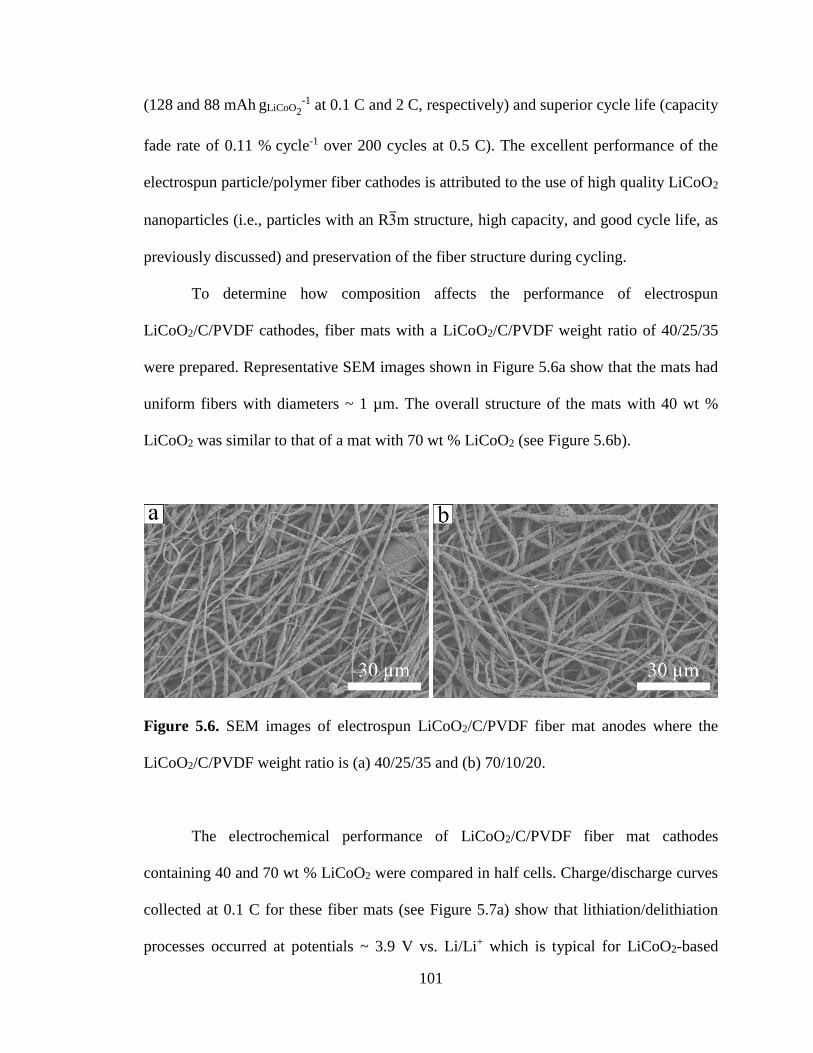
101
(128 and 88 mAh gLiCoO2-1 at 0.1 C and 2 C, respectively) and superior cycle life (capacity
fade rate of 0.11 % cycle-1 over 200 cycles at 0.5 C). The excellent performance of the
electrospun particle/polymer fiber cathodes is attributed to the use of high quality LiCoO2
nanoparticles (i.e., particles with an R3m structure, high capacity, and good cycle life, as
previously discussed) and preservation of the fiber structure during cycling.
To determine how composition affects the performance of electrospun
LiCoO2/C/PVDF cathodes, fiber mats with a LiCoO2/C/PVDF weight ratio of 40/25/35
were prepared. Representative SEM images shown in Figure 5.6a show that the mats had
uniform fibers with diameters ~ 1 µm. The overall structure of the mats with 40 wt %
LiCoO2 was similar to that of a mat with 70 wt % LiCoO2 (see Figure 5.6b).
Figure 5.6. SEM images of electrospun LiCoO2/C/PVDF fiber mat anodes where the
LiCoO2/C/PVDF weight ratio is (a) 40/25/35 and (b) 70/10/20.
The electrochemical performance of LiCoO2/C/PVDF fiber mat cathodes
containing 40 and 70 wt % LiCoO2 were compared in half cells. Charge/discharge curves
collected at 0.1 C for these fiber mats (see Figure 5.7a) show that lithiation/delithiation
processes occurred at potentials ~ 3.9 V vs. Li/Li+ which is typical for LiCoO2-based
102
cathodes. The reversible capacity of electrodes with 40 and 70 wt % LiCoO2 were 51 and
87 mAh g-1, respectively, and each electrode had good active material utilization with
~ 125 mAh gLiCoO2-1. Figure 5.7b shows the cycling stability of each electrode was
excellent, with no capacity fade over 10 cycles. The gravimetric capacity of these
electrodes was evaluated at charge/discharge rates ranging from 0.1 – 2 C as shown in
Figure 5.7c. At all C-rates investigated, the gravimetric capacity of the cathode with
70 wt % LiCoO2 was greater than that of the fiber mat with 40 wt % LiCoO2, indicating
that increasing the carbon content from 10 to 25 wt % did not provide any improvement
in the performance of LiCoO2/C/PVDF cathodes up to 2 C. Thus, the remainder of the
present study focused on characterizing fiber mat cathodes with a LiCoO2/C/PVDF
weight ratio of 70/10/20.
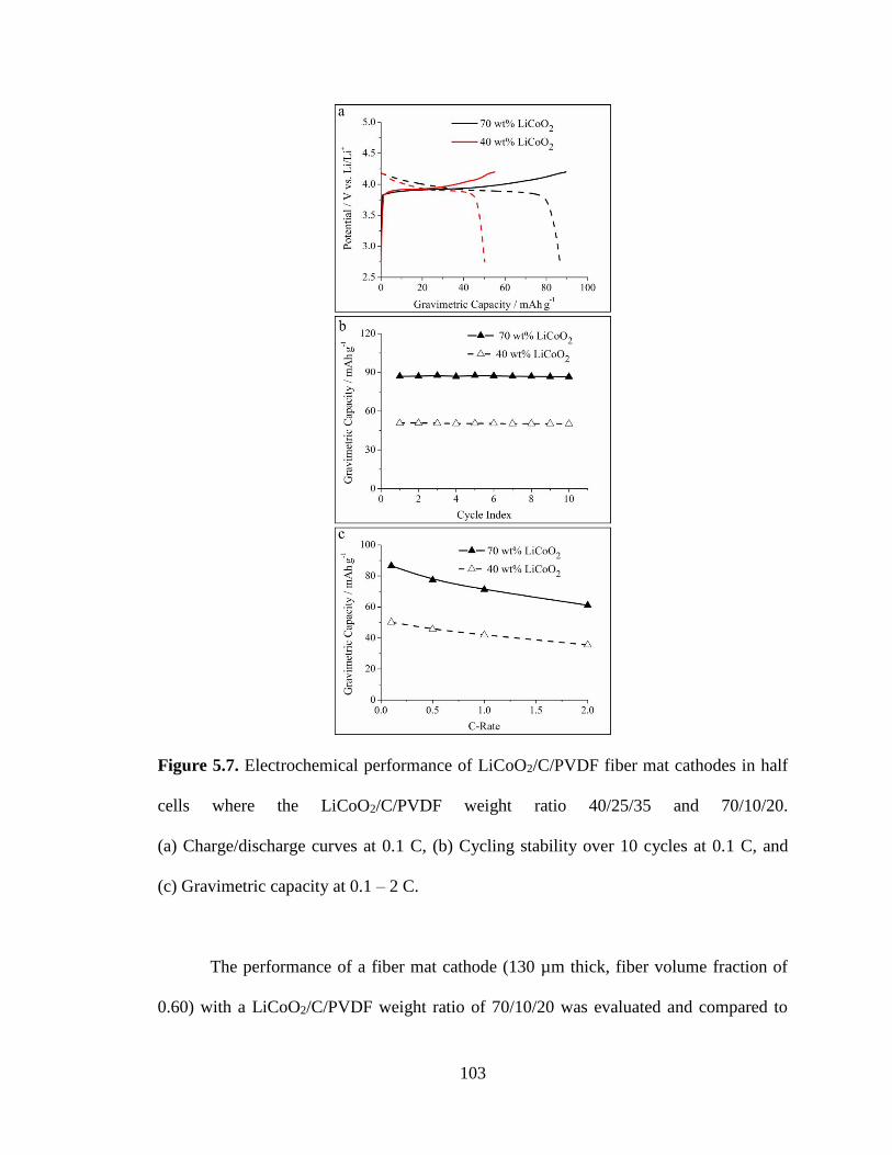
103
Figure 5.7. Electrochemical performance of LiCoO2/C/PVDF fiber mat cathodes in half
cells where the LiCoO2/C/PVDF weight ratio 40/25/35 and 70/10/20.
(a) Charge/discharge curves at 0.1 C, (b) Cycling stability over 10 cycles at 0.1 C, and
(c) Gravimetric capacity at 0.1 – 2 C.
The performance of a fiber mat cathode (130 µm thick, fiber volume fraction of
0.60) with a LiCoO2/C/PVDF weight ratio of 70/10/20 was evaluated and compared to

104
that of a slurry cast cathode (120 µm thick) of the same composition in half cell tests.
Figure 5.8a shows the gravimetric capacity of the electrospun and slurry cast cathodes at
charge/discharge rates ranging from 0.1 – 2 C; the performance in Figure 5.8a was
representative for samples tested in triplicate. At 0.1 C the electrospun and slurry cast
cathodes exhibited similar gravimetric capacities ~ 80 mAh g-1 (114 mAh gLiCoO2-1)
indicating good active material utilization at a slow charge/discharge rate. The
electrospun cathode exhibited excellent rate capabilities with reversible capacities of
71 and 61 mAh g-1 at 1 C and 2 C, respectively, compared to 53 mAh g-1 at 1 C and
0.25 mAh g-1 at 2 C for the slurry cast cathode. It should be noted that the performance of
the slurry cast cathode prepared in the present study (see Figure 5.8a) was similar to that
reported by Stephenson et al.[51] for an electrode containing LiCoO2/C/PVDF in a 91/6/3
weight ratio, where the capacity at 2.5 C was 15 mAh g-1. Compared to the slurry cast
electrodes, the excellent performance of the electrospun cathode is attributed to the small
fiber diameter and the intra/interfiber void space of the mat which allowed for electrolyte
infiltration throughout the electrode, a large electrode/electrolyte interfacial area, and
efficient Li+ transport between the electrolyte and active material nanoparticles.

105
Figure 5.8. Rate capabilities of electrospun and slurry cast LiCoO2/C/PVDF cathodes.
(a) Gravimetric (b) areal, and (c) volumetric capacities at 0.1 – 2 C. All electrodes
contained LiCoO2/C/PVDF in a 70/10/20 weight ratio.
Areal and volumetric capacities, which are important for battery design and
electrode assessment, were determined at 0.1 – 2 C for an electrospun mat (130 µm thick,
fiber volume fraction of 0.60) and a slurry cast cathode (120 µm thick) of the same

106
composition. The results are shown in Figures 5.8b and 5.8c. At a 0.1 C charge/discharge
rate, both electrodes had an areal capacity of ~ 1.1 mAh cm-2. The electrospun cathode
retained a high capacity of 0.95 and 0.81 mAh cm-2 at 1 C and 2 C, respectively, whereas
the slurry cast cathode had very poor rate capabilities at high C-rates, with an areal
capacity of only 0.78 mAh cm-2 at 1 C and essentially no reversible capacity at 2 C
(0.004 mAh cm-2). Similarly, there was only a slight decrease in volumetric capacity of
the electrospun cathode as the charging rate was increased from 0.1 C to 1 C and 2 C
(82 , 73, and 62 mAh cm-3, respectively) as shown in Figure 5.8c. In comparison, the
volumetric capacity of a slurry electrode was high at 0.1 C (91 mAh cm-3) but decreased
significantly at higher C-rates (e.g., 0.30 mAh cm-3 at 2 C).
The results in Figures 5.4, 5.7, and 5.8 were collected for half cells containing a
LiCoO2/C/PVDF cathode and Li metal counter/reference electrode. Half cells provide a
convenient and reliable way to characterize individual electrodes, but Li metal anodes
cannot be utilized in consumer devices due to Li dendrite formation.[52, 53] To evaluate a
more practical and relevant LIB device, full cells containing a LiCoO2/C/PVDF cathode
and a carbon powder/PVDF anode (C/PVDF[7], described in Chapter IV) were prepared
and characterized.
Figure 5.9a shows typical charge/discharge curves at 0.1 – 2 C for a full cell
containing an electrospun LiCoO2/C/PVDF cathode (fiber volume fraction of 0.86 and
thickness of 180 µm) and electrospun C/PVDF fiber mat anode (fiber volume fraction of
0.56 and thickness of 280 µm). The sloping profiles of the charge/discharge curves are
due to the wide operating potential of the C/PVDF anode[7] where lithiation/delithiation
processes occur from 0.015 – 1.5 V vs. Li/Li+. At 0.1 C, the initial gravimetric capacity
107
of the full cell was 49 mAh g-1 (normalized to the combined mass of the cathode and
anode) which corresponded well to the theoretical capacity Qtotal (51 mAh g-1) calculated
using equation 5.1:
1
Qtotal
= 1
Qcathode
+ 1
Qanode
(5.1)
where Qcathode and Qanode are the effective gravimetric capacities of the cathode and
anode, taking into account the active and inactive components of the electrodes
(80 and 140 mAh g-1 for the cathode and anode, respectively). Good agreement between
the measured capacity and theoretical capacity indicates that the anode and cathode active
materials were well-utilized in the cell. After storing the full cell with electrospun
electrodes for 168 h at open-circuit, 87 % of the discharge capacity was retained. Such a
self-discharge rate is typical for LIBs; Du Pasquier et al.[54] reported that a battery
containing a LiCoO2 cathode and Li4Ti5O12 anode retained 93 % of its discharge capacity
after 200 h of storage at open-circuit.

108
Figure 5.9. Electrochemical characterization of full cells containing a LiCoO2/C/PVDF
cathode and C/PVDF anode. (a) Charge/discharge curves at 0.1 – 2 C for a full cell with
an electrospun cathode/anode and (b) cycling stability at 0.1 – 2 C for full cells
containing either electrospun electrodes or slurry cast electrodes.
The performance of a full cell containing an electrospun LiCoO2/C/PVDF cathode
and electrospun C/PVDF anode was compared to that of a full cell prepared with slurry
cast electrodes of the same composition. Gravimetric capacities of the electrospun and
slurry cast cells at 0.1 – 2 C are shown in Figure 5.9b. Both cells exhibited similar
capacities of ~ 44 mAh g-1 at 0.1 C, but the electrospun battery had superior rate
capabilities with a 73 % higher capacity at 2 C (15.4 mAh g-1 for the fiber electrodes vs.
8.9 mAh g-1 for the slurry cast full cell). The data in Table 5.1 show that the full cell with
electrospun electrodes also had higher areal and volumetric capacities at 1 C and 2 C
compared to that of the slurry cast full cell. Furthermore, the capacity at 0.1 C was fully
recovered in both cells after cycling at rates varying between 0.5 – 2 C as shown in
Figure 5.9b.

109
Table 5.1. Areal and volumetric capacities of full cells containing LiCoO2/C/PVDF
cathodes and C/PVDF anodes.
Full Cell Areal Capacity (mAh cm-2) Volumetric Capacity (mAh cm-3)
0.1 C 1 C 2 C 0.1 C 1 C 2 C
Electrospun
Cathode + Anode 1.76 1.03 0.64 37.7 22.1 13.7
Slurry Cast
Cathode + Anode 1.75 0.68 0.34 38.6 15.0 7.5
Only two other literature reports have characterized full cells containing an
electrospun cathode and anode. Aravindan and Jayaraman et al.[55] prepared electrospun
LiMn2O4 nanofibers (for the cathode) and electrospun TiO2 nanofibers (for the anode)
using sol-gel chemistry and high temperature processing. The authors reported a
gravimetric capacity of 100 mAh g-1 and an energy density of 220 Wh kg-1, but these
values were normalized only to the mass of the active cathode material. For a more
meaningful comparison with data in the present paper, the overall mass of both sol-gel
fiber electrodes was used to re-calculate an effective gravimetric capacity of 50 mAh g-1
and energy density of 111 Wh kg-1 for the electrospun LiMn2O4/TiO2 full cell. The same
group[56] also reported on a full cell containing an electrospun LiMn2O4 cathode and
electrospun TiNb2O7 anode with an effective gravimetric capacity of 58 mAh g-1, areal
capacity ~ 0.5 mAh cm-2, and an effective energy density of 139 Wh kg-1 at 0.52 C. For
comparison, the full cell of the present study with an electrospun LiCoO2/C/PVDF
cathode and C/PVDF anode had a comparable gravimetric capacity of 42 mAh g-1 and
energy density of 144 Wh kg-1 at 0.1 C but a much higher areal capacity
(up to 1.76 mAh cm-2, as per Table 5.1).
110
5.4 Conclusions
Particle/polymer electrospinning was used to prepare fiber mat cathodes for
LIBs, where the fibers contained 70 wt % LiCoO2 nanoparticles, 10 wt % carbon powder,
and 20 wt % poly(vinylidene) binder (LiCoO2/C/PVDF). The fiber cathode exhibited a
high gravimetric capacity of 90 mAh g-1 (128 mAh gLiCoO2-1) and good cycling stability
(only 0.11 % capacity fade cycle-1 which is superior to previous reports on electrospun
LiCoO2 electrodes).
Thick, densely packed LiCoO2/C/PVDF fiber mats were prepared for high areal
and volumetric capacity cathodes. The areal and volumetric capacities at 0.1 C of a
130 µm thick electrospun mat cathode with a fiber volume fraction of 0.60 were
1.1 mAh cm-2 and 82 mAh cm-3, respectively. Electrospun cathodes also exhibited
excellent rate capabilities, with capacity retentions of 89 % at 1 C and 76 % at 2 C, vs. a
slurry cast electrode of the same composition which had a capacity retention of 70 % at
1 C and essentially no reversible capacity at 2 C.
Full cells containing an electrospun cathode (LiCoO2/C/PVDF) and electrospun
anode (C/PVDF) were also prepared and characterized. The full cells had a high
gravimetric capacity (42 mAh g-1) and energy density (144 Wh kg-1) at 0.1 C. Notably,
the areal and volumetric capacities of the electrospun full cell were 1.03 mAh cm-2 and
22.1 mAh cm-3 at 1 C. This performance was significantly better than that of a full cell
containing slurry cast electrodes of the same composition (0.68 mAh cm-2 and
15.0 mAh cm-3 at 1 C) and full cells reported in the literature containing electrospun
electrodes prepared through sol-gel chemistry (e.g., ~ 0.5 mAh cm-2 at 0.52 C).

111
The results in this paper show that particle/polymer fiber electrospinning is a
robust platform for the preparation of LIB electrodes with high gravimetric, areal, and
volumetric capacities at fast charge/discharge rates. Electrodes can be prepared with high
particle content, and the polymer binder is retained in the final electrode structure. The
excellent performance of the LiCoO2/C/PVDF fiber cathodes reported here is attributed
to the intra- and interfiber void space which allows for good electrolyte infiltration
throughout the electrode mat, a large electrode/electrolyte interfacial area, and short Li+
transport pathways between the electrolyte and active material in the radial fiber
direction. The presence of a polymer binder in the fibers is also beneficial, making the
electrode mechanically flexible and allowing for some electrolyte uptake into the fibers
for better Li+ ion transport. Overall these results demonstrate that incorporating nanoscale
active materials into 3D electrospun fiber mats improves battery performance compared
to conventional materials.

112
5.5 References
[1] J.-M. Tarascon, M. Armand, Nature 2001, 414, 359.
[2] M. Armand, J.-M. Tarascon, Nature 2008, 451, 652.
[3] P. N. Pintauro, Polym. Rev. 2015, 55, 201.
[4] N. Nitta, G. Yushin, Part. Part. Syst. Char. 2014, 31, 317.
[5] S. J. Kim, M. Naguib, M. Zhao, C. Zhang, H.-T. Jung, M. W. Barsoum, Y.
Gogotsi, Electrochim. Acta 2015, 163, 246.
[6] E. C. Self, R. Wycisk, P. N. Pintauro, J. Power Sources 2015, 282, 187.
[7] E. C. Self, E. C. McRen, P. N. Pintauro, ChemSusChem 2016, 9, 208.
[8] C. Fongy, A. C. Gaillot, S. Jouanneau, D. Guyomard, B. Lestriez, J. Electrochem.
Soc. 2010, 157, A885.
[9] S. K. Martha, J. O. Kiggans, J. Nanda, N. J. Dudney, J. Electrochem. Soc. 2011,
158, A1060.
[10] M. Singh, J. Kaiser, H. Hahn, J. Electrochem. Soc. 2015, 162, A1196.
[11] X. Zhang, T. W. Verhallen, F. Labohm, M. Wagemaker, Adv. Energy Mater.
2015, 5, 1500498.
[12] W. Zhang, P. N. Pintauro, ChemSusChem 2011, 4, 1753.
[13] M. Brodt, R. Wycisk, P. N. Pintauro, J. Electrochem. Soc. 2013, 160, F744.
[14] M. Brodt, T. Han, N. Dale, E. Niangar, R. Wycisk, P. Pintauro, J. Electrochem.
Soc. 2014, 162, F84.
[15] S. R. Sivakkumar, J. Y. Nerkar, A. G. Pandolfo, Electrochim. Acta 2010, 55,
3330.
[16] S. Kalluri, K. H. Seng, Z. Guo, H. K. Liu, S. X. Dou, RSC Advances 2013, 3,
25576.
[17] H.-G. Wang, S. Yuan, D.-L. Ma, X.-B. Zhang, J.-M. Yan, Energy Environ. Sci.
2015, 8, 1660.
[18] Z.-W. Fu, J. Ma, Q.-Z. Qin, Solid State Ionics 2005, 176, 1635.
[19] Y. Gu, D. Chen, X. Jiao, J. Phys. Chem. B 2005, 109, 17901.
[20] Y. Gu, D. Chen, X. Jiao, F. Liu, J. Mater. Chem. 2007, 17, 1769.
[21] H.-W. Lu, L. Yu, W. Zeng, Y.-S. Li, Z.-W. Fu, Electrochem. Solid-State Lett.
2008, 11, A140.
[22] Y. Mizuno, E. Hosono, T. Saito, M. Okubo, D. Nishio-Hamane, K. Oh-ishi, T.
Kudo, H. Zhou, J. Phys. Chem. C 2012, 116, 10774.
[23] Y. Ou, J. Wen, H. Xu, S. Xie, J. Li, J. Phys. Chem. Solids 2013, 74, 322.
[24] H. Yang, J.-H. Pee, H. T. Kim, Y. Kim, J. Ceram. Process. Res. 2012, 13, 319.
[25] J.-P. Park, J.-Y. Park, C.-H. Hwang, M.-H. Choi, J.-E. Kim, K.-M. Ok, I.-W.
Shim, Bull. Korean Chem. Soc. 2010, 31, 327.
[26] H. M. Rietveld, J. Appl. Cryst. 1969, 2, 65.
[27] J. Rodríguez-Carvajal, Physica B 1993, 192, 55.
[28] F. Bonino, S. Brutti, P. Reale, B. Scrosati, L. Gherghel, J. Wu, K. Müllen, Adv.
Mater. 2005, 17, 743.
[29] A. Caballero, L. Hernan, J. Morales, ChemSusChem 2011, 4, 658.
[30] I. R. M. Kottegoda, Y. Kadoma, H. Ikuta, Y. Uchimoto, M. Wakihara, J.
Electrochem. Soc. 2005, 152, A1595.
[31] Ó. Vargas, Á. Caballero, J. Morales, Electrochim. Acta 2015, 165, 365.
113
[32] C. Chae, H. Park, D. Kim, J. Kim, E.-S. Oh, J. K. Lee, J. Power Sources 2013,
244, 214.
[33] J. Hassoun, F. Croce, I. Hong, B. Scrosati, Electrochem. Commun. 2011, 13, 228.
[34] R. Kataoka, T. Mukai, A. Yoshizawa, T. Sakai, J. Electrochem. Soc. 2013, 160,
A1684.
[35] K.-L. Lee, J.-Y. Jung, S.-W. Lee, H.-S. Moon, J.-W. Park, J. Power Sources
2004, 130, 241.
[36] R. Verrelli, J. Hassoun, A. Farkas, T. Jacob, B. Scrosati, J. Mater. Chem. A 2013,
1, 15329.
[37] Y. Wang, Y. Wang, D. Jia, Z. Peng, Y. Xia, G. Zheng, Nano Lett. 2014, 14, 1080.
[38] S.-T. Myung, N. Kumagai, S. Komaba, H.-T. Chung, J. Appl. Electrochem. 2000,
30, 1081.
[39] O. A. Shlyakhtin, S. H. Choi, Y. S. Yoon, Y.-J. Oh, Electrochim. Acta 2004, 50,
511.
[40] Y. Shao-Horn, L. Croguennec, C. Delmas, E. C. Nelson, M. A. O'Keefe, Nat.
Mater. 2003, 2, 464.
[41] J. T. Hertz, Q. Huang, T. McQueen, T. Klimczuk, J. W. G. Bos, L. Viciu, R. J.
Cava, Phys. Rev. B 2008, 77, 075119.
[42] M. Inaba, Y. Inriyama, Z. Ogumi, Y. Todzuka, A. Tasaka, J. Raman Spectrosc.
1997, 28, 613.
[43] S. Tintignac, R. Baddour-Hadjean, J.-P. Pereira-Ramos, R. Salot, Electrochim.
Acta 2012, 60, 121.
[44] M. Jo, Y.-S. Hong, J. Choo, J. Cho, J. Electrochem. Soc. 2009, 156, A430.
[45] B. Huang, Y.-I. Jang, Y.-M. Chiang, D. R. Sadoway, J. Appl. Electrochem. 1998,
28, 1365.
[46] E. I. Santiago, A. V. C. Andrade, C. O. Paiva-Santos, L. O. S. Bulhões, Solid
State Ionics 2003, 158, 91.
[47] Y.-M. Chiang, D. R. Sadoway, Y.-I. Jang, B. Huang, H. Wang, Electrochem.
Solid-State Lett. 1999, 2, 107.
[48] R. Koksbang, J. Barker, H. Shi, M. Y. Saïdi, Solid State Ionics 1996, 84, 1.
[49] M. Sathiya, A. S. Prakash, K. Ramesha, A. K. Shukla, Materials 2009, 2, 857.
[50] A. Kondo, E. Nakamura, T. Kozawa, H. Abe, M. Naito, J. Yoshida, S. Nakanishi,
H. Iba, Adv. Powder Technol. 2014, 25, 1280.
[51] D. E. Stephenson, E. M. Hartman, J. N. Harb, D. R. Wheeler, J. Electrochem.
Soc. 2007, 154, A1146.
[52] V. Aravindan, Y.-S. Lee, S. Madhavi, Adv. Energy Mater. 2015, 5, 1402225.
[53] J. B. Goodenough, Acc. Chem. Res. 2013, 46, 1053.
[54] A. Du Pasquier, I. Plitz, S. Menocal, G. Amatucci, J. Power Sources 2003, 115,
171.
[55] V. Aravindan, J. Sundaramurthy, P. S. Kumar, N. Shubha, W. C. Ling, S.
Ramakrishna, S. Madhavi, Nanoscale 2013, 5, 10636.
[56] S. Jayaraman, V. Aravindan, P. Suresh Kumar, W. Chui Ling, S. Ramakrishna, S.
Madhavi, ACS Appl. Mater. Interfaces 2014, 6, 8660.

114
CHAPTER VI
ELECTROSPUN PARTICLE/POLYMER SI-BASED NANOFIBER ANODES FOR LI-
ION BATTERIES
6.1 Introduction
Since their commercial debut in 1991, Li-ion batteries (LIBs) have revolutionized
the functionality of portable electronic devices, and the LIB industry continues to grow
today due emerging applications such as electric vehicle propulsion.[1, 2] Despite the
extraordinary success of LIBs, many devices are still limited by battery performance, and
thus new batteries with higher energy density and long cycle life must be developed to
satisfy the ever-increasing demands of consumers.[3, 4]
Si has been widely investigated as a replacement for graphite in today’s LIB
anodes due to its high theoretical capacity (3,600 mAh g-1 for Li15Si4 vs. 372 mAh g-1 for
LiC6) and low operating potential (< 0.5 V vs. Li/Li+).[5, 6] However, Si-based anodes
often exhibit poor cycling stability due to large volume changes during charging and
discharging. Lithiation of Si is accompanied by a volumetric expansion exceeding 300 %,
and repeated swelling and shrinking of Si during battery cycling results in capacity fade
due to Si pulverization, electronic isolation of Si particles, and irreversible Li
consumption associated with repeated formation and rupture of the solid-electrolyte
interphase (SEI) layer.[7, 8] Although Si pulverization can be eliminated through the use of
nanoscale active materials (e.g., Si nanoparticles[9-11] and Si nanowires[12-15]), effective
techniques which prevent electronic isolation of Si and stabilize the SEI layer are yet to
115
be identified.[7, 8] Furthermore, previously reported nanoscale Si anodes typically
contained low active material loadings and densities, resulting in low areal and
volumetric capacities. To produce Si anodes which are suitable for commercial
applications, new anode designs which can tolerate Si volumetric changes while
maintaining high gravimetric, areal, and volumetric capacities over many
charge/discharge cycles must be developed.
One attractive Si anode design involves the use of an electrospun nanofiber mat
with interfiber voids which can accommodate the volumetric changes of Si during
cycling.[16, 17] Previous studies[18-24] on electrospun Si anodes have largely been directed
towards the pyrolysis of polymer fibers with embedded Si particles to create an
electronically conductive Si-C nanofiber network. Freestanding Si-C nanofiber mats
exhibited high gravimetric capacities (e.g., 800 – 1,600 mAh g-1) and good stability over
30 – 100 cycles, but most of these studies neglected to examine carefully the anode’s
areal and volumetric capacities. Si areal loadings in many electrospinning studies were
very low (e.g., < 0.1 mgSi cm-2)[24, 25], and SEM images suggested that the fiber volume
fraction of the mats were far too low (< 0.25) for practical battery use.
An alternative to pyrolyzed carbon fiber-based electrodes is the use of electrospun
particle/polymer fiber mat electrodes, an approach that has been pursued by Pintauro and
coworkers.[26-28] The preparation and characterization of several particle/polymer fiber
mat LIB electrodes have been reported, including: (i) anodes containing titania
nanoparticles, carbon powder, and poly(acrylic acid) (TiO2/C/PAA)[26] (Chapter III),
(ii) anodes containing carbon powder and poly(vinylidene fluoride) (C/PVDF)[27]
(Chapter IV), and (iii) cathodes containing LiCoO2 nanoparticles, carbon powder, and
116
PVDF (LiCoO2/C/PVDF)[28] (Chapter V). These studies showed that fiber mats with a
high material loading (e.g., 54.1 mg cm-2) and high fiber volume fractions (up to 0.86)
worked exceptionally well, with high areal and volumetric capacities at fast
charge/discharge rates (e.g., 1.3 mAh cm-2 and 62 mAh cm-3 at 2 C). The excellent
performance of electrospun particle/polymer fiber mat electrodes is attributed to: (i) a
large electrode/electrolyte interfacial area, (ii) short Li+ transport pathways between the
electrolyte and active material in the radial fiber direction, and (iii) good electrolyte
infiltration throughout the electrode via the intra- and interfiber void space of the mat.
Based on our encouraging prior results with electrospun particle/polymer
electrodes containing moderate capacity materials[26-28], it made sense to apply the
technique to high capacity Si-based anodes. A particle/polymer fiber mat containing Si
nanoparticles offers several advantages over previously reported Si-C fiber anodes
prepared via high temperature pyrolysis. The presence of the polymer binder ensures that
particle/polymer fiber mats can be compacted under high pressure without fracturing, and
thus thick, densely packed nanofiber electrodes can be created for high gravimetric, areal,
and volumetric capacities.[26-28] For practical battery applications, high areal capacities
are desired to reduce the amount of inactive cell components (e.g., current collectors,
separators, etc.), and batteries with a high volumetric capacity allow more energy to be
stored within a given space.[6, 26-28] Electrospun particle/polymer fibers can also be made
with a binder that absorbs electrolyte, ensuring that Li+ ions have access to most/all Si
nanoparticles in the electrode. Furthermore, the binder in such fiber mats can be chosen
to help stabilize the Si particles during charge/discharge cycling, as has been reported for

117
electronically conductive binders[29-32] and binders like PAA[33], carboxymethyl
cellulose[34], and alginate[35] which form hydrogen bonds with the SiOx layer on Si.
The present paper describes the preparation and characterization of two types of
electrospun particle/polymer fiber mat LIB anodes including: (i) Si nanoparticles, carbon
black, and PAA binder (hereafter denoted as Si/C/PAA) and (ii) Si nanoparticles and
electronically conductive polymer binders (PFM and PEFM, synthesized by Gao Liu and
coworkers at Lawrence Berkeley National Laboratory). Qualitative
performance/composition/structure correlations are established by evaluating the
performance of fiber mats with different compositions, fiber volume fractions, interfiber
connectivities, thicknesses, and loadings. Electrodes are characterized both in half cells
using a Li metal counter/reference electrode and in full cells prepared with an electrospun
fiber mat LiCoO2/C/PVDF cathode.
6.2 Experimental
This study investigated several Si-based anodes including: (i) Si nanoparticles (50
– 70 nm), carbon powder (Vulcan XC-72R, Fuel Cell Store), and poly(acrylic acid)
(PAA, Mv = 450,000 g mol-1, Sigma-Aldrich) (Si/C/PAA, electrospun only), (ii) Si
nanoparticles and PFM, an electronically conductive polymer binder (Si/PFM,
electrospun and slurry cast), and (iii) Si nanoparticles and PEFM, another conductive
polymer binder (Si/PEFM, slurry cast only). 1 wt % poly(ethylene oxide)
(PEO, Mv = 1 MDa) was added as a carrier polymer to facilitate the electrospinning
process for fibers containing the PFM binder. Electrode inks were prepared by mixing the
components in n-propanol (for Si/C/PAA), a 1/1 mixture of chlorobenzene/chloroform

118
(for Si/PFM), or chlorobenzene (for Si/PEFM). The Si/C/PAA electrodes contained either
15 or 40 wt % Si, and the anodes prepared with electronically conductive polymer binder
contained between 35 – 67 wt % Si.
Slurry cast anodes were prepared by casting the electrode ink onto a copper foil
current collector (9 µm, MTI Corp.) and drying at ambient conditions. Fiber mat anodes
were created by electrospinning using a single needle spinneret and the custom-made
rotating drum collector as described in Chapter IV.[27] Si/C/PAA fiber mats were spun
onto an aluminum foil substrate at the following conditions: (i) 0.75 and 1.00 mL h-1
solution flow rates for anodes with 15 and 40 wt % Si, respectively, (ii) 8 kV bias
voltage, (iii) 8.0 cm spinneret-to-collector distance, and (iv) 20 – 30 % relative humidity
(rh). Si/PFM/PEO fiber mats were prepared at the following conditions: (i) solution flow
rates of 0.25 – 0.50 mL h-1, (ii) 5 – 6 kV bias voltage, (iii) 8.0 cm spinneret-to-collector
distance, and (iv) 15 – 75 % rh. Top-down morphology of the electrospun mats was
assessed using scanning electron microscopy (Hitachi S4200 and Zeiss Merlin SEMs).
Several types of Si/C/PAA anodes were prepared with 40 wt % Si. The first was
an as-spun mat with a fiber volume fraction of ~ 0.30. The others were compacted and/or
welded mats, which were prepared by: (i) mechanically compacting an as-spun mat on a
hydraulic press at 90 MPa for 40 s to increase the fiber volume fraction and/or
(ii) exposing the mat to methanol vapor for 1 h at room temperature to weld the interfiber
contacts. For Si/C/PAA anodes prepared with 15 wt % Si, only a compacted/welded fiber
mat was tested. The fiber volume fraction of all compacted mats was 0.80 ± 0.05 as
determined by analysis of SEM images of fiber mats using ImageJ as described in
119
Chapter IV.[27] For Si/PFM/PEO anodes, only as-spun mats which were neither
compacted nor welded were investigated.
CR2032 half cells were constructed in an argon-filled glovebox using an
electrospun fiber mat (dried overnight at 70 °C under vacuum) as the working electrode
and a Li metal counter/reference electrode. The electrolyte was 1.2 M LiPF6 in a mixture
of ethylene carbonate and diethyl carbonate (3/7 by volume, BASF Corp.). 30 wt %
fluoroethylene carbonate (BASF Corp.) was added to the electrolyte to ensure formation
of a stable SEI layer. Two sheets of Celgard 2500 soaked in electrolyte were used as a
membrane separator, and several additional drops of electrolyte were added to completely
fill the cell volume. Cells were crimped at 1,000 psi and rested overnight before
electrochemical characterization. Galvanostatic charge/discharge experiments were
conducted by polarizing the cells between 0.015 – 1.5 V at 0.1 – 1 C on an 8-channel
battery tester (5 V/1 mA, MTI Corp.). C-rates for the half cells were calculated assuming
a theoretical capacity of 3,600 mAh g-1 for Si and 372 mAh g-1 for carbon. At least two
coin cells were tested for each sample to assess the reproducibility of these experiments.
The electrochemical performance of each sample was reproducible within approximately
15 – 20 % among independent coin cell tests. Except where otherwise indicated, half cell
capacities are normalized with respect to the entire composite anode (e.g., total amounts
of Si, C, and PAA).
Selected half cells were disassembled after cycling, and the anodes were rinsed
using dimethyl carbonate before conducting post-mortem analysis. Cross-sectional SEM
images of pristine (i.e., uncycled) and cycled fiber mat anodes were collected using a
Zeiss Merlin VP microscope (Carl Zeiss Microscopy GmbH, Oberkochen, Germany).

120
The cross-sectional investigations were carried out on electrodes broken into halves after
freezing them in liquid nitrogen. Raman spectra of pristine and cycled fiber mat anodes
were acquired using an Alpha 300 confocal Raman microscope (WITec, GmbH) with a
solid-state 532 nm excitation laser, 100x objective, and a grating with 600 grooves mm-1.
Raman maps with a spatial resolution on the order of 1 µm and a pixel density of
9 pixels µm-2 were collected with an integration time of 2 s per spectrum. The laser power
was attenuated to 1 mW for analysis of the pristine electrode. The laser power was further
reduced to 100 µW for analysis of the cycled sample to prevent crystallization of the
amorphous silicon from laser-induced heating. Raman maps were analyzed using WITec
Project Plus software.
A CR2032 full cell containing an electrospun Si/C/PAA anode and an electrospun
LiCoO2/C/PVDF cathode was assembled and tested. The LiCoO2/C/PVDF fiber mat
cathode was prepared using the ink formulation and electrospinning procedure described
in Chapter V. The full cell contained the same electrolyte and separator as used in the
half cells. To minimize the irreversible capacity loss in the full cell, the Si/C/PAA anode
and LiCoO2/C/PVDF cathode were preconditioned in half cells for at least 10 cycles at
0.1 C, as has been done in other studies.[28, 36-45] The anode/cathode mass ratio in the full
cell was 1/13 to ensure good capacity matching of the electrodes (N/P capacity ratio of
0.89). The full cell was characterized using galvanostatic charge/discharge cycling
between 2.50 – 4.20 V at 0.1 C, where the C-rate was calculated based on the measured
capacity of the cathode. Full cell capacities were normalized with respect to both
electrodes (i.e., the combined amounts of the Si/C/PAA anode and LiCoO2/C/PVDF
cathode).
121
6.3 Results and Discussion
6.3.1 Anodes with Poly(acrylic acid) (PAA) Binder
Freestanding fiber mats containing Si nanoparticles, carbon powder, and a
poly(acrylic acid) binder (Si/C/PAA) were fabricated using electrospinning. Preparing
particle/polymer fiber mats with a uniform particle distribution requires optimization of
several experimental parameters (e.g., ink composition, flow rate, electric field strength,
etc.), and thus appropriate ink formulation and electrospinning conditions were
determined empirically rather than through a priori means. In the present study, fiber
mats containing Si/C/PAA in a weight ratio of 40/25/35 were produced using n-propanol
as the solvent and a fixed ink flow rate of 1.00 mL h-1, applied bias voltage of 8 kV, and a
spinneret-to-collector distance of 8 cm, as these conditions were used in our previous
report on TiO2-based fiber mat anodes.[26] Ink formulation and relative humidity during
electrospinning were then optimized to form Si/C/PAA fiber mats. The solids content of
the inks (i.e., combined amounts of Si nanoparticles, carbon powder, and PAA) was
varied from 10 – 30 wt %, and 17 – 18 wt % solids was found to be optimal. Inks
containing > 25 wt % solids could not be dispersed using magnetic stirring and
sonication, and inks with 10 – 15 wt % solids had low viscosities which were not
appropriate for electrospinning. Relative humidity (rh) during electrospinning had a
significant impact on the properties of the fiber mats. Electrospinning at > 30 % rh
resulted in the deposition of fibers which could not be peeled from the collector,
presumably due to incomplete solvent evaporation of the fiber jet. On the other hand,
freestanding fiber mats were produced by electorspinning at 20 – 30 % rh, and thus these
conditions were used in the present study.

122
Scanning electron microscopy (SEM) images of an electrospun nanofiber mat
containing Si nanoparticles, carbon black, and poly(acrylic acid) (Si/C/PAA) in a
40/25/35 weight ratio are shown in Figure 6.1. The as-spun mat had a fiber volume
fraction of 0.30 and an average fiber diameter of 980 nm with some bead-on-fiber
formation (see Figures 6.1a and 6.1b); these observations were typical for fiber mats
prepared in this study. Compacting the mat increased the fiber volume fraction to 0.85,
whereas welding the mat improved the interfiber connectivity. As shown in Figures 6.1c
and 6.1d, a compacted/welded fiber mat maintained some interfiber void space, and
corresponding cross-sectional SEM images presented in Figures 6.2a and 6.2b
demonstrate that the fiber volume fraction was uniform throughout the mat and that the
interfiber contact nodes were successfully welded. Compared to the as-spun mat, the
compacted/welded mat was mechanically stiffer, confirming the presence of these fused
fiber crossings. The interfiber connectivity was also assessed by measuring the electrical
resistance over a 2 cm section of mat using an ohmmeter with point-type probes. The
measured resistance of a compacted/welded mat was ~ 1,000 times lower than that of an
as-spun mat (4 vs. 3,000 kΩ), indicating the compacted/welded fiber mat had much better
interfiber connectivity.

123
Figure 6.1. Top-down SEM images of electrospun nanofiber mats containing Si/C/PAA
in a 40/25/35 weight ratio. (a,b) an as-spun fiber mat and (c,d) a compacted/welded fiber
mat.
Figure 6.2. (a) Low and (b) high magnification cross-sectional SEM images of a
compacted/welded fiber mat containing Si/C/PAA in a 40/25/35 weight ratio.

124
The performance of an as-spun nanofiber mat anode with a Si/C/PAA weight ratio
of 40/25/35 was compared to that of a compacted/welded mat of the same composition.
Figure 6.3a shows charge/discharge curves collected at 0.1 C for each electrode during
the first two cycles. The shape of these curves are typical for Si-based anodes where
lithiation and delithiation reactions occur at potentials < 0.5 V vs. Li/Li+.[5] Both
electrodes exhibited high lithiation capacities ~ 1,700 mAh g-1 during the first cycle, but
the as-spun mat had a low reversible capacity of 1,064 mAh g-1 (corresponding to
2,500 mAh gSi-1 and 67 % coulombic efficiency), suggesting some fibers in the as-spun
mat were electronically isolated during the first delithiation half cycle. In comparison, the
compacted/welded fiber mat anode had excellent Si utilization as evidenced by a high
reversible capacity of 1,484 mAh g-1 (corresponding to 3,500 mAh gSi-1 and 85 %
coulombic efficiency) which was essentially unchanged during the second
charge/discharge cycle.
Figure 6.3b shows the gravimetric capacity over 50 cycles at 0.1 C of four
electrospun anodes with a Si/C/PAA weight ratio of 40/25/35, including: (i) an as-spun
mat, (ii) a compacted (unwelded) mat, (iii) a welded (uncompacted) mat, and (iv) a
compacted/welded mat. The fiber volume fractions of the uncompacted and compacted
mats were approximately 0.30 and 0.85, respectively. The as-spun mat had the lowest
initial capacity of 1,064 mAh g-1 which faded steadily to 218 mAh g-1 after 50 cycles. In
comparison, the compacted/welded fiber mat anode showed reasonably good cycling
performance with reversible capacities of 1,484 and 1,083 mAh g-1 during the 1st and 50th
cycles, respectively. Mats which were only welded or only compacted showed
intermediate cycling performance. These results demonstrate that mats with a fiber

125
volume fraction of 0.85 and welded interfiber contacts have sufficient void space for
electrolyte infiltration throughout the electrode and mechanical strength to withstand the
large volumetric changes of Si during cycling. Conversely, mats with a low fiber volume
fraction (~ 0.30) and/or poor interfiber connectivity cannot tolerate reversible Si
swelling/shrinking.

126
Figure 6.3. Electrochemical characterization of electrospun anodes containing Si/C/PAA
in a 40/25/35 weight ratio. (a) Charge/discharge curves for the 1st and 2nd cycles (solid
and dashed lines, respectively) for as-spun and compacted/welded fiber mats and
(b) gravimetric capacity over 50 cycles at 0.1 C for as-spun, compacted (unwelded),
welded (uncompacted), and compacted/welded fiber mats.
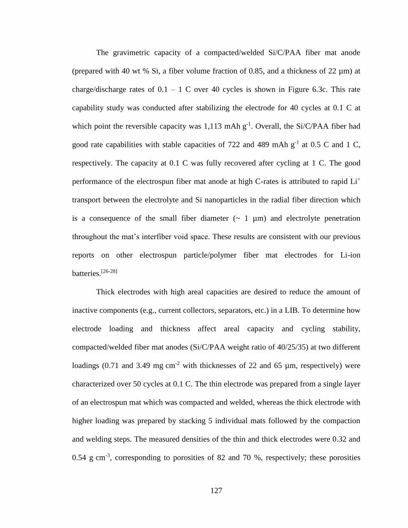
127
The gravimetric capacity of a compacted/welded Si/C/PAA fiber mat anode
(prepared with 40 wt % Si, a fiber volume fraction of 0.85, and a thickness of 22 µm) at
charge/discharge rates of 0.1 – 1 C over 40 cycles is shown in Figure 6.3c. This rate
capability study was conducted after stabilizing the electrode for 40 cycles at 0.1 C at
which point the reversible capacity was 1,113 mAh g-1. Overall, the Si/C/PAA fiber had
good rate capabilities with stable capacities of 722 and 489 mAh g-1 at 0.5 C and 1 C,
respectively. The capacity at 0.1 C was fully recovered after cycling at 1 C. The good
performance of the electrospun fiber mat anode at high C-rates is attributed to rapid Li+
transport between the electrolyte and Si nanoparticles in the radial fiber direction which
is a consequence of the small fiber diameter (~ 1 µm) and electrolyte penetration
throughout the mat’s interfiber void space. These results are consistent with our previous
reports on other electrospun particle/polymer fiber mat electrodes for Li-ion
batteries.[26-28]
Thick electrodes with high areal capacities are desired to reduce the amount of
inactive components (e.g., current collectors, separators, etc.) in a LIB. To determine how
electrode loading and thickness affect areal capacity and cycling stability,
compacted/welded fiber mat anodes (Si/C/PAA weight ratio of 40/25/35) at two different
loadings (0.71 and 3.49 mg cm-2 with thicknesses of 22 and 65 µm, respectively) were
characterized over 50 cycles at 0.1 C. The thin electrode was prepared from a single layer
of an electrospun mat which was compacted and welded, whereas the thick electrode with
higher loading was prepared by stacking 5 individual mats followed by the compaction
and welding steps. The measured densities of the thin and thick electrodes were 0.32 and
0.54 g cm-3, corresponding to porosities of 82 and 70 %, respectively; these porosities
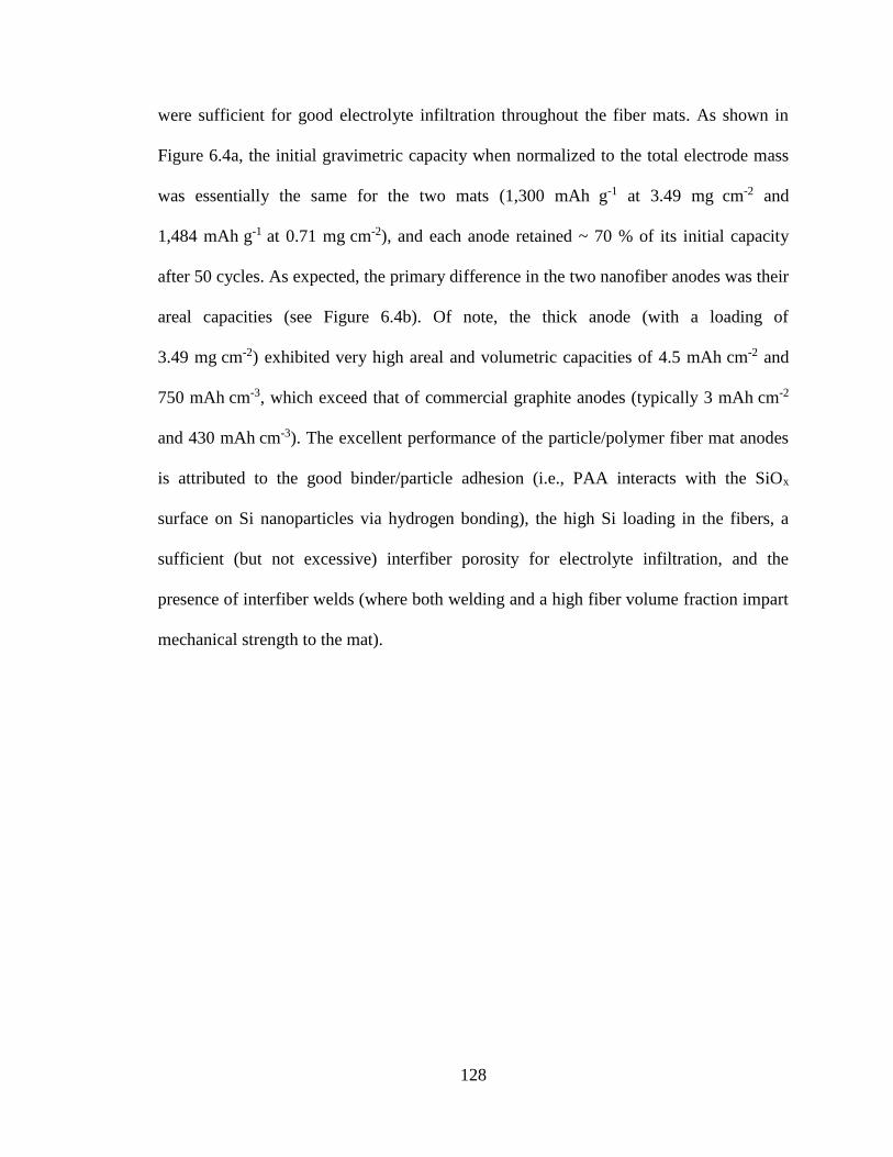
128
were sufficient for good electrolyte infiltration throughout the fiber mats. As shown in
Figure 6.4a, the initial gravimetric capacity when normalized to the total electrode mass
was essentially the same for the two mats (1,300 mAh g-1 at 3.49 mg cm-2 and
1,484 mAh g-1 at 0.71 mg cm-2), and each anode retained ~ 70 % of its initial capacity
after 50 cycles. As expected, the primary difference in the two nanofiber anodes was their
areal capacities (see Figure 6.4b). Of note, the thick anode (with a loading of
3.49 mg cm-2) exhibited very high areal and volumetric capacities of 4.5 mAh cm-2 and
750 mAh cm-3, which exceed that of commercial graphite anodes (typically 3 mAh cm-2
and 430 mAh cm-3). The excellent performance of the particle/polymer fiber mat anodes
is attributed to the good binder/particle adhesion (i.e., PAA interacts with the SiOx
surface on Si nanoparticles via hydrogen bonding), the high Si loading in the fibers, a
sufficient (but not excessive) interfiber porosity for electrolyte infiltration, and the
presence of interfiber welds (where both welding and a high fiber volume fraction impart
mechanical strength to the mat).

129
Figure 6.4. (a) Gravimetric capacity and (b) areal capacity of compacted/welded
Si/C/PAA nanofiber mats over 50 cycles at 0.1 C. Electrodes at two different loadings
(0.71 and 3.49 mg cm-2) were characterized. The electrodes contained Si/C/PAA in a
40/25/35 weight ratio.
The performance of the compacted/welded Si/C/PAA fiber mat anodes in Figure
6.4 compare well to electrospun Si-based anodes reported in the literature. Xiao et al.[25]
prepared and characterized a coaxial electrospun nanofiber mat prepared by sputtering a
Si layer onto Ni-plated PVDF nanofibers. The electrode exhibited a high capacity when
normalized to the Si active material (3,210 mAh gSi-1), but the Si loading in the fibers was
only 18.1 wt %, corresponding to an effective gravimetric capacity of 581 mAh g-1.
Furthermore, this electrode had a very low material loading of 0.08 mg cm-2, with an
areal capacity of 0.046 mAh cm-2 which is far too low for practical battery applications.
In another study, Xu et al.[22] prepared a 3D Si/C fiber anode by electrospinning
poly(acrylonitrile) fibers and electrospraying Si nanoparticles., followed by high
temperature pyrolysis to create an electronically conductive nanofiber network. The
electrode exhibited stable performance over 100 cycles with high gravimetric and
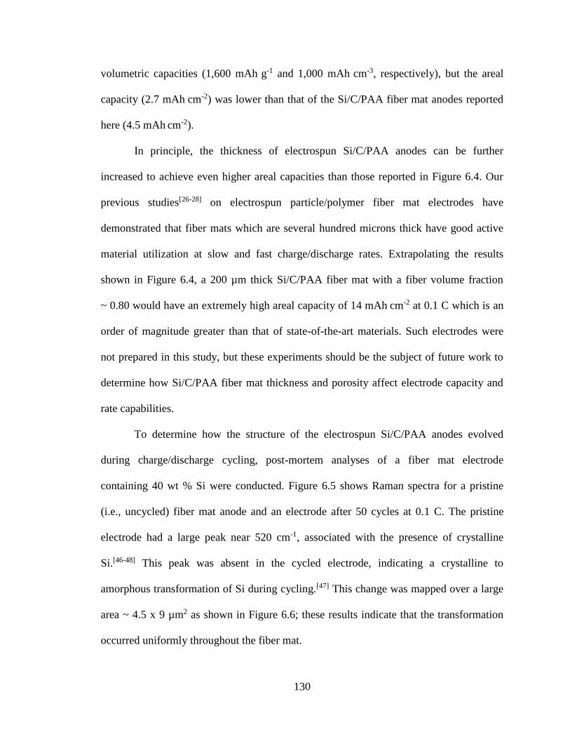
130
volumetric capacities (1,600 mAh g-1 and 1,000 mAh cm-3, respectively), but the areal
capacity (2.7 mAh cm-2) was lower than that of the Si/C/PAA fiber mat anodes reported
here (4.5 mAh cm-2).
In principle, the thickness of electrospun Si/C/PAA anodes can be further
increased to achieve even higher areal capacities than those reported in Figure 6.4. Our
previous studies[26-28] on electrospun particle/polymer fiber mat electrodes have
demonstrated that fiber mats which are several hundred microns thick have good active
material utilization at slow and fast charge/discharge rates. Extrapolating the results
shown in Figure 6.4, a 200 µm thick Si/C/PAA fiber mat with a fiber volume fraction
~ 0.80 would have an extremely high areal capacity of 14 mAh cm-2 at 0.1 C which is an
order of magnitude greater than that of state-of-the-art materials. Such electrodes were
not prepared in this study, but these experiments should be the subject of future work to
determine how Si/C/PAA fiber mat thickness and porosity affect electrode capacity and
rate capabilities.
To determine how the structure of the electrospun Si/C/PAA anodes evolved
during charge/discharge cycling, post-mortem analyses of a fiber mat electrode
containing 40 wt % Si were conducted. Figure 6.5 shows Raman spectra for a pristine
(i.e., uncycled) fiber mat anode and an electrode after 50 cycles at 0.1 C. The pristine
electrode had a large peak near 520 cm-1, associated with the presence of crystalline
Si.[46-48] This peak was absent in the cycled electrode, indicating a crystalline to
amorphous transformation of Si during cycling.[47] This change was mapped over a large
area ~ 4.5 x 9 µm2 as shown in Figure 6.6; these results indicate that the transformation
occurred uniformly throughout the fiber mat.

131
Figure 6.5. Raman spectra of Si/C/PAA fiber mat anodes before and after 50 cycles at
0.1 C. The electrodes contained Si/C/PAA in a 40/25/35 weight ratio.
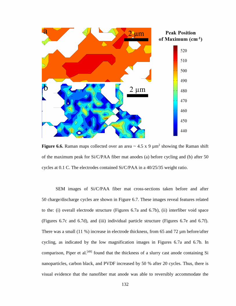
132
Figure 6.6. Raman maps collected over an area ~ 4.5 x 9 µm2 showing the Raman shift
of the maximum peak for Si/C/PAA fiber mat anodes (a) before cycling and (b) after 50
cycles at 0.1 C. The electrodes contained Si/C/PAA in a 40/25/35 weight ratio.
SEM images of Si/C/PAA fiber mat cross-sections taken before and after
50 charge/discharge cycles are shown in Figure 6.7. These images reveal features related
to the: (i) overall electrode structure (Figures 6.7a and 6.7b), (ii) interfiber void space
(Figures 6.7c and 6.7d), and (iii) individual particle structure (Figures 6.7e and 6.7f).
There was a small (11 %) increase in electrode thickness, from 65 and 72 µm before/after
cycling, as indicated by the low magnification images in Figures 6.7a and 6.7b. In
comparison, Piper et al.[49] found that the thickness of a slurry cast anode containing Si
nanoparticles, carbon black, and PVDF increased by 50 % after 20 cycles. Thus, there is
visual evidence that the nanofiber mat anode was able to reversibly accommodate the
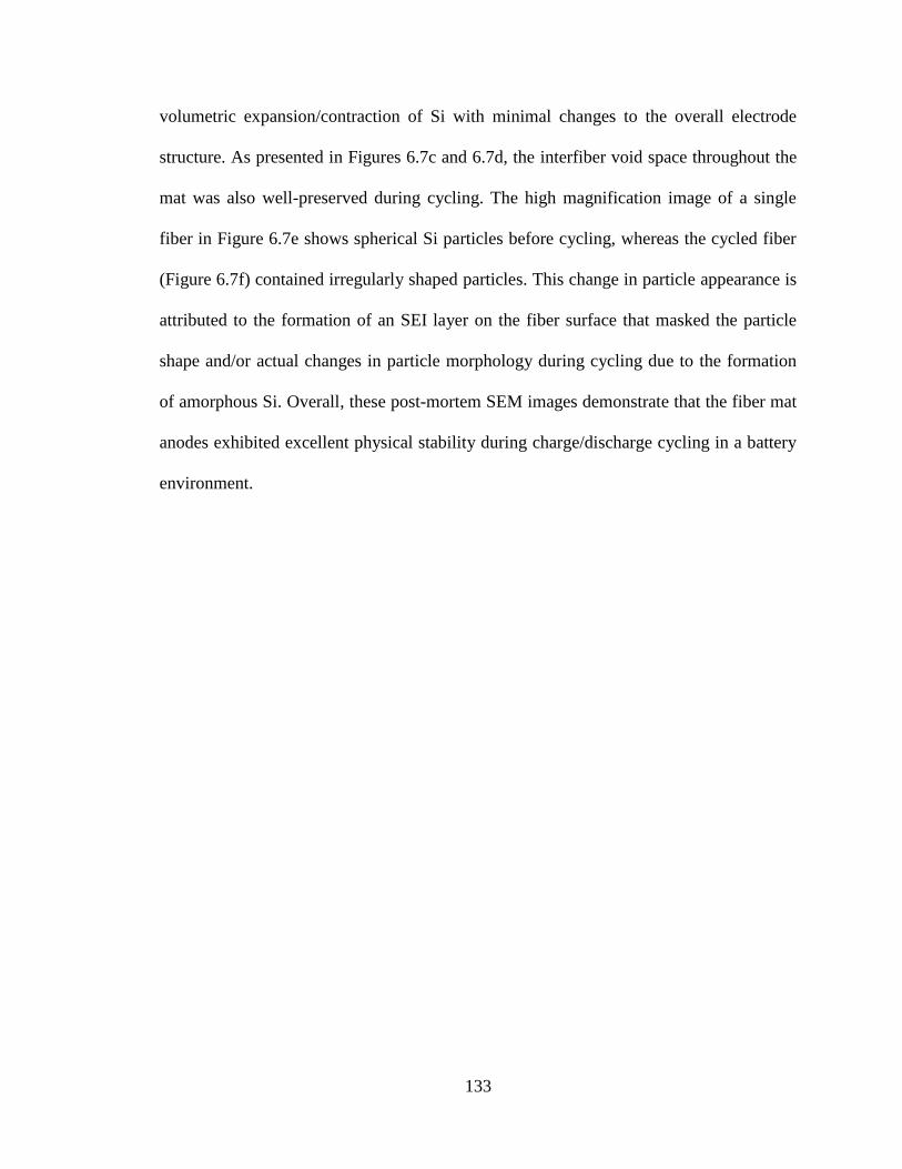
133
volumetric expansion/contraction of Si with minimal changes to the overall electrode
structure. As presented in Figures 6.7c and 6.7d, the interfiber void space throughout the
mat was also well-preserved during cycling. The high magnification image of a single
fiber in Figure 6.7e shows spherical Si particles before cycling, whereas the cycled fiber
(Figure 6.7f) contained irregularly shaped particles. This change in particle appearance is
attributed to the formation of an SEI layer on the fiber surface that masked the particle
shape and/or actual changes in particle morphology during cycling due to the formation
of amorphous Si. Overall, these post-mortem SEM images demonstrate that the fiber mat
anodes exhibited excellent physical stability during charge/discharge cycling in a battery
environment.
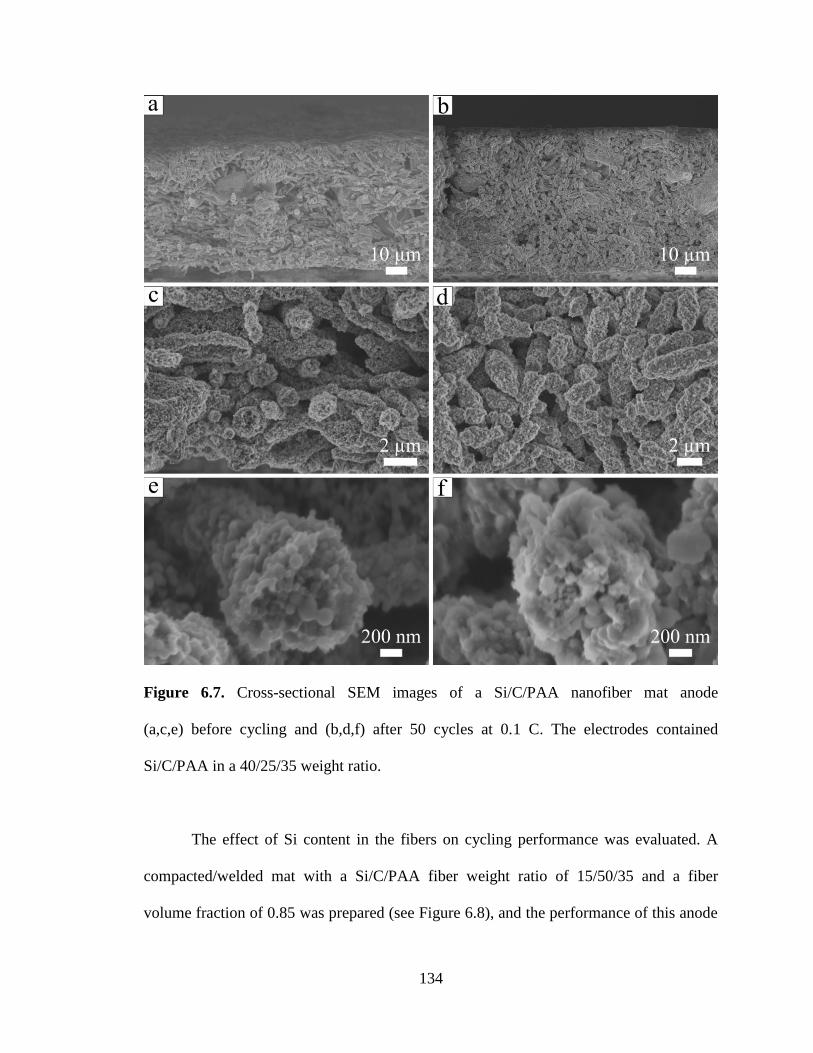
134
Figure 6.7. Cross-sectional SEM images of a Si/C/PAA nanofiber mat anode
(a,c,e) before cycling and (b,d,f) after 50 cycles at 0.1 C. The electrodes contained
Si/C/PAA in a 40/25/35 weight ratio.
The effect of Si content in the fibers on cycling performance was evaluated. A
compacted/welded mat with a Si/C/PAA fiber weight ratio of 15/50/35 and a fiber
volume fraction of 0.85 was prepared (see Figure 6.8), and the performance of this anode

135
was compared to that of a compacted/welded mat where the fibers contained 40 wt % Si.
The areal loading of Si in both anodes was fixed at ~ 0.26 mgSi cm-2 which translates to a
theoretical areal capacity of ~ 1 mAh cm-2. In order to achieve this areal capacity match,
the mat with 15 wt % Si was made thicker (40 µm vs. 22 µm for the anode with
40 wt % Si). As shown in Figure 6.9a, the anode with 15 wt % Si had a lower effective
gravimetric capacity (582 mAh g-1 vs. 1,484 mAh g-1) due to the lower Si content in the
fibers, but both electrodes exhibited good Si utilization with reversible capacities
> 3,000 mAh gSi-1. Figure 6.9b shows that the anode with lower Si content displayed
excellent cycling stability with 90 % capacity retention after 50 cycles vs. 73 % capacity
retention for the anode containing 40 wt % Si. The better cycling stability of the
15 wt % Si anode is attributed to smaller net volume changes of the fibers during
charging and discharging. Overall, these results demonstrate that the lower effective
gravimetric capacity of the anode containing 15 wt % Si can be offset by increasing the
electrode thickness to achieve the same areal capacity as a fiber mat with a higher Si
weight fraction.

136
Figure 6.8. SEM image of a compacted/welded nanofiber mat with a fiber volume
fraction of 0.85 and Si/C/PAA in a 15/50/35 weight ratio.
Figure 6.9. Electrochemical characterization of compacted/welded nanofiber mat anodes
containing Si/C/PAA weight ratios of 40/25/35 and 15/50/35. (a) Gravimetric capacity
and (b) capacity retention over 50 cycles at 0.1 C.
As an alternative to Si nanoparticle-based fiber mat anodes, electrospun fiber mats
containing Si nanowires, carbon powder, and PAA binder were also prepared and
137
characterized. The performance of as-spun Si/C/PAA fiber mats (i.e., mats which were
neither compacted nor welded) containing either Si nanowires or Si nanoparticles were
compared in half cells as discussed in Appendix C. In short, these experiments showed
that electrospun anodes prepared with Si nanowires had a lower reversible capacity of
432 mAh g-1 at 0.1 C but better cycling stability with 68 % capacity retention after
50 cycles (compared to 1,001 mAh g-1 and 21 % capacity retention for an as-spun anode
with Si nanoparticles). The lower capacity of the Si nanowires may be due to the
presence of a thick (~ 10 nm) SiOx passive layer on the nanowire surface as determined
by Jagjit Nanda and coworkers at Oak Ridge National Laboratory using x-ray
photoelectron spectroscopy (results not shown). Since the Si nanowires had lower
gravimetric capacities, they were not further investigated in the present study.
Most of the existing literature on Si-based anodes focuses exclusively on half cell
characterizations, but electrode performance in full cells is critical for practical battery
applications.[6, 8, 28] To evaluate electrode performance under more realistic testing
conditions, a full cell containing an electrospun Si/C/PAA anode (with a Si/C/PAA
weight ratio of 40/25/35) and an electrospun LiCoO2/C/PVDF cathode[28] was prepared
and characterized.
Figure 6.10a shows a typical charge/discharge curve at 0.1 C for the electrospun
Si/LiCoO2 full cell. During discharge, the cell had an average operating potential of 3.6 V
and a reversible capacity of 75 mAh g-1 (normalized to the combined mass of both
electrodes) which corresponds well to the theoretical capacity of 77 mAh g-1 based on the
individual capacities of the anode and cathode. Agreement between the measured and
theoretical capacities indicates good active material utilization for the Si-based anode and
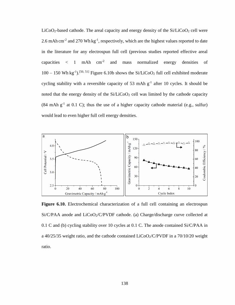
138
LiCoO2-based cathode. The areal capacity and energy density of the Si/LiCoO2 cell were
2.6 mAh cm-2 and 270 Wh kg-1, respectively, which are the highest values reported to date
in the literature for any electrospun full cell (previous studies reported effective areal
capacities < 1 mAh cm-2 and mass normalized energy densities of
100 – 150 Wh kg-1).[50, 51] Figure 6.10b shows the Si/LiCoO2 full cell exhibited moderate
cycling stability with a reversible capacity of 53 mAh g-1 after 10 cycles. It should be
noted that the energy density of the Si/LiCoO2 cell was limited by the cathode capacity
(84 mAh g-1 at 0.1 C); thus the use of a higher capacity cathode material (e.g., sulfur)
would lead to even higher full cell energy densities.
Figure 6.10. Electrochemical characterization of a full cell containing an electrospun
Si/C/PAA anode and LiCoO2/C/PVDF cathode. (a) Charge/discharge curve collected at
0.1 C and (b) cycling stability over 10 cycles at 0.1 C. The anode contained Si/C/PAA in
a 40/25/35 weight ratio, and the cathode contained LiCoO2/C/PVDF in a 70/10/20 weight
ratio.

139
6.3.2 Anodes with Electronically Conductive Polymer Binders
Two electronically conductive polymer binders [poly(9,9-dioctylfluorene-co-
fluorenone-co-methylbenzoic ester) (PFM) and poly(2,7-9,9-dioctylfluorene-co-2,7-9,9-
(di(oxy-2,5,8- trioxadecane)) fluorine-co-2,7-fluorenone-co-2,5-1-methylbenzoic ester)
(PEFM)] with electrical conductivities ~ 1 x 10⁻⁶ S m-1 were synthesized by Gao Liu and
coworkers at Lawrence Berkeley National Laboratory as described previously.[29, 52] The
structures of PFM and PEFM are shown in Figure 6.11. Electrospinning studies and
electrochemical characterization of Si-based anodes containing PFM and PEFM binders
were conducted at Vanderbilt.
Figure 6.11. Structure of the electronically conductive polymer binders, PFM and PEFM.
Image adapted from Wu et al.[52] with permission from The American Chemical Society.
A PFM solution containing 5 wt % PFM in a chlorobenzene/chloroform solvent
(1/1 by weight) was electrospun at the conditions given in Table 6.1. As shown in
Figures 6.12a and 6.12b, the neat PFM fibers contained an undesirable bead-on-fiber
morphology. To improve the spinnability of PFM, a poly(ethylene oxide) (PEO) carrier
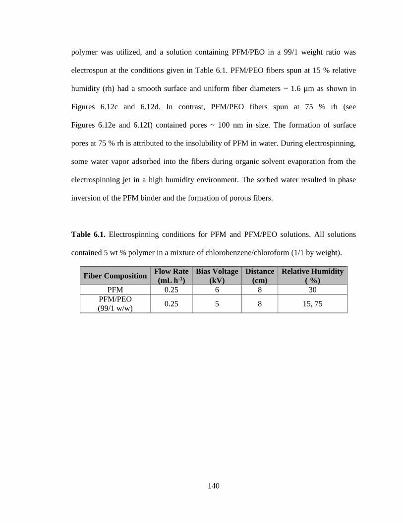
140
polymer was utilized, and a solution containing PFM/PEO in a 99/1 weight ratio was
electrospun at the conditions given in Table 6.1. PFM/PEO fibers spun at 15 % relative
humidity (rh) had a smooth surface and uniform fiber diameters ~ 1.6 µm as shown in
Figures 6.12c and 6.12d. In contrast, PFM/PEO fibers spun at 75 % rh (see
Figures 6.12e and 6.12f) contained pores ~ 100 nm in size. The formation of surface
pores at 75 % rh is attributed to the insolubility of PFM in water. During electrospinning,
some water vapor adsorbed into the fibers during organic solvent evaporation from the
electrospinning jet in a high humidity environment. The sorbed water resulted in phase
inversion of the PFM binder and the formation of porous fibers.
Table 6.1. Electrospinning conditions for PFM and PFM/PEO solutions. All solutions
contained 5 wt % polymer in a mixture of chlorobenzene/chloroform (1/1 by weight).
Fiber Composition Flow Rate
(mL h-1)
Bias Voltage
(kV)
Distance
(cm)
Relative Humidity
( %)
PFM 0.25 6 8 30
PFM/PEO
(99/1 w/w) 0.25 5 8 15, 75

141
Figure 6.12. SEM images of electrospun (a,b) neat PFM fibers and (c – f) PFM/PEO
fibers prepared at (c,d) 15 % rh and (e,f) 75 % rh. The PEO carrier polymer content in
(b – f) was 1 wt %.
Electrospun fiber mats containing Si nanoparticles, PFM binder, and PEO carrier
polymer were prepared. The solids content in the inks was 10 wt %, and two fiber
compositions (Si/PFM/PEO weight ratios of 35/64/1 and 50/49/1) were investigated. The

142
electrospinning conditions used to form fibers containing either 35 or 50 wt % Si are
listed in Table 6.2, and SEM images of the fibers are shown in Figure 6.13. The fibers
containing 35 wt % Si (see Figures 6.13a and 6.13b) had a uniform particle distribution
and an average fiber diameter ~ 1.5 µm. In comparison, the sample containing 50 wt % Si
(see Figures 6.13c and 6.13d) exhibited a bead-on-fiber morphology with fiber diameters
up to 9 µm. The rh during electrospinning had a large impact on the structure of
Si/PFM/PEO fibers containing 50 wt % Si. As shown in Figure 6.14a, fibers spun at
15 % rh had a dense structure, whereas spinning at 75 % rh formed porous fibers. These
observations are consistent with the experiments conducted on PFM/PEO fibers
containing no Si nanoparticles discussed previously.
Table 6.2. Electrospinning conditions for inks containing Si/PFM/PEO containing 35 and
50 wt % Si.
Fiber
Composition
Flow Rate
(mL h-1)
Bias Voltage
(kV)
Distance
(cm)
Relative Humidity
( %)
Si/PFM/PEO
(35/64/1 w/w/w) 0.25 5 8 75
Si/PFM/PEO
(50/49/1 w/w/w) 0.50 5 8 15, 75

143
Figure 6.13. SEM images of electrospun Si/PFM/PEO fiber mats containing: (a,b) 35 wt
% Si and (c,d) 50 wt % Si. All samples contained 1 wt % PEO as a carrier polymer, and
electrospinning was conducted at 75 % rh.
Figure 6.14. SEM images of fiber mats containing a Si/PFM/PEO weight ratio of 50/49/1
which were electrospun at (a) 15 % rh and (b) 75 % rh.
144
The electrochemical performance of electrospun and slurry cast anodes containing
Si/PFM/PEO in a 50/49/1 weight ratio was evaluated in half cells. Typical
charge/discharge curves collected at 0.1 C for these electrodes are shown in Figure 6.15.
Surprisingly, all of these anodes exhibited virtually no reversible capacity (< 15 mAh g-1).
These observations were consistent for multiple experiments conducted at Vanderbilt and
LBNL. Similar results were obtained for a Si/PFM slurry cast anode (containing no PEO
polymer), indicating that PEO is not the cause of the electrodes’ low capacity. Instead, it
is likely that the PFM binder in these electrodes formed a thick, ionically insulating layer
around the Si nanoparticles which inhibited Li+ transport to the active material during
battery cycling. One way to reduce the thickness of the polymer binder coating is to
increase the Si/PFM ratio in the electrode. Thus, a series of Si/PFM slurry cast anodes
with different compositions (Si/PFM weight ratios of 50/50, 55/45, 60/40, and 67/33)
were prepared and characterized in half cells.
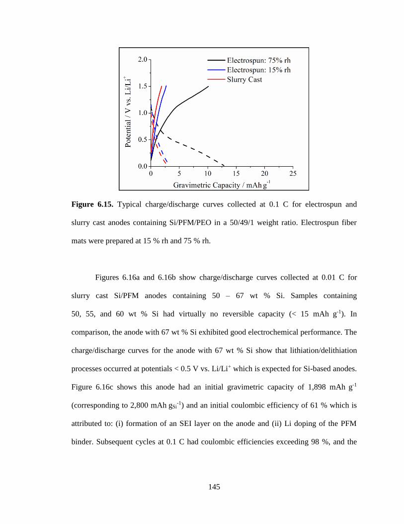
145
Figure 6.15. Typical charge/discharge curves collected at 0.1 C for electrospun and
slurry cast anodes containing Si/PFM/PEO in a 50/49/1 weight ratio. Electrospun fiber
mats were prepared at 15 % rh and 75 % rh.
Figures 6.16a and 6.16b show charge/discharge curves collected at 0.01 C for
slurry cast Si/PFM anodes containing 50 – 67 wt % Si. Samples containing
50, 55, and 60 wt % Si had virtually no reversible capacity (< 15 mAh g-1). In
comparison, the anode with 67 wt % Si exhibited good electrochemical performance. The
charge/discharge curves for the anode with 67 wt % Si show that lithiation/delithiation
processes occurred at potentials < 0.5 V vs. Li/Li+ which is expected for Si-based anodes.
Figure 6.16c shows this anode had an initial gravimetric capacity of 1,898 mAh g-1
(corresponding to 2,800 mAh gSi-1) and an initial coulombic efficiency of 61 % which is
attributed to: (i) formation of an SEI layer on the anode and (ii) Li doping of the PFM
binder. Subsequent cycles at 0.1 C had coulombic efficiencies exceeding 98 %, and the
146
electrode had good cycling stability with a reversible capacity of 1,239 mAh g-1 after
50 cycles.
The results in Figure 6.16 demonstrate that Si/PFM anodes must contain
< 40 wt % PFM to achieve good electrochemical performance. The reason for poor
performance at higher PFM loadings is not yet fully understood, but it is presumed that
the electrodes prepared with ≥ 40 wt % PFM had a thick polymer coating on the Si
nanoparticles which made them electrochemically inaccessible even at very slow
charge/discharge rates (e.g., 0.01 C). Future studies should focus on: (i) preparing
electrospun Si/PFM fibers with 67 wt % Si and (ii) decreasing the fiber diameter to
facilitate Li+ transport between the electrolyte and Si nanoparticles in the radial fiber
direction.
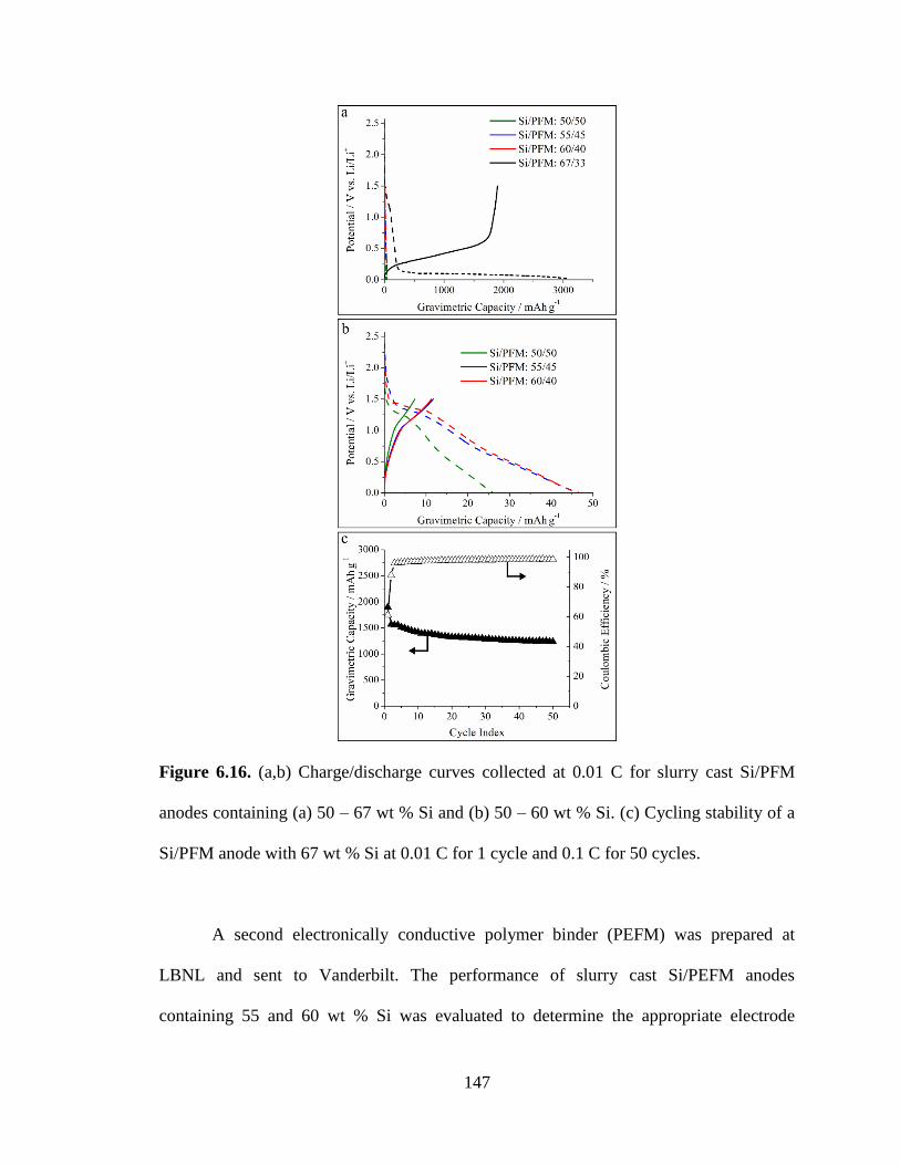
147
Figure 6.16. (a,b) Charge/discharge curves collected at 0.01 C for slurry cast Si/PFM
anodes containing (a) 50 – 67 wt % Si and (b) 50 – 60 wt % Si. (c) Cycling stability of a
Si/PFM anode with 67 wt % Si at 0.01 C for 1 cycle and 0.1 C for 50 cycles.
A second electronically conductive polymer binder (PEFM) was prepared at
LBNL and sent to Vanderbilt. The performance of slurry cast Si/PEFM anodes
containing 55 and 60 wt % Si was evaluated to determine the appropriate electrode

148
composition target for electrospun Si/PEFM fiber mat anodes to be developed in future
studies.
Figure 6.17a shows charge/discharge curves collected at 0.01 C for slurry cast
Si/PEFM anodes containing 55 and 60 wt % Si (45 and 40 wt % PEFM, respectively).
Compared to Si/PFM slurry cast anodes which had poor performance with these binder
contents, the Si/PEFM anodes with 55 and 60 wt % Si had high reversible capacities of
1,526, and 1,559 mAh g-1, respectively. Figure 6.17b shows the Si/PEFM anode
containing 60 wt % Si had good cycling stability with a reversible capacity of
948 mAh g-1 after 50 cycles at 0.1 C. These results demonstrate that the PEFM-containing
anodes had better electrochemical performance at binder contents up to 45 wt %
compared to that of the Si/PFM system. The superior performance of the Si/PEFM
electrodes may be attributed to the presence of the binder’s PEO sidechains (see Figure
6.11) which swell with battery electrolyte and thus provide better access of Li+ to the Si
active material.

149
Figure 6.17. (a) Charge/discharge curves collected at 0.01 C for slurry cast Si/PEFM
anodes containing 55 and 60 wt % Si. (b) Cycling stability of a Si/PEFM anode with
60 wt % Si over 1 cycle at 0.01 C and 50 cycles at 0.1 C.
6.4 Conclusions
Particle/polymer electrospinning was used to prepare fiber mat LIB anodes
containing Si nanoparticles and carbon black with poly(acrylic acid) as the binder
(Si/C/PAA). A compacted/welded fiber mat containing 40 wt % Si had a high gravimetric
capacity of 1,484 mAh g-1 (3,500 mAh gSi-1) and good cycling stability with
73 % capacity retention after 50 cycles at 0.1 C. The anode also had good rate capabilities
with a reversible capacity of 489 mAh g-1 at 1 C. A fiber mat anode of the same
composition which was neither compacted nor welded performed poorly, with an initial
capacity of 1,064 mAh g-1 and 20 % capacity retention after 50 cycles. Compacting and
welding improved the mechanical strength of an electrospun mat, but sufficient void
space remained in the electrode to accommodate the large volumetric changes of Si
during charge/discharge cycling. The effect of Si content in the fibers on cycling
performance was also evaluated. An electrospun Si/C/PAA fiber mat anode containing

150
15 wt % Si performed better than an electrospun anode prepared with 40 wt % Si. The
anode with 15 wt % Si had a lower effective gravimetric capacity (582 mAh g-1), but it
exhibited superior cycling stability (90 % capacity retention after 50 cycles) due to
smaller overall volumetric changes during cycling. Anodes containing 15 and 40 wt % Si
(with thicknesses of 40 and 22 µm, respectively) were prepared with the same Si areal
loading, demonstrating that the lower effective gravimetric capacity of a fiber mat anode
with low Si content can be offset by utilizing a thicker electrode.
Post-mortem analyses of electrospun anodes were conducted to determine how
the fiber mat structure changed during charge/discharge cycling. Raman spectroscopy
showed that there was a conversion of crystalline Si to amorphous Si during cycling.
Cross-sectional SEM images indicated good physical stability of the anodes in a battery
environment, with preservation of the fiber mat structure and interfiber void space during
cycling.
Whereas Si anodes prepared by electrospinning followed by fiber pyrolysis have
low material loadings and mat densities which limit their use in practical devices,
particle/polymer electrospinning can be used to prepare thick, densely packed fiber mats
with high loadings for high areal and volumetric capacities. A compacted/welded
nanofiber mat containing 40 wt % Si and a material loading of 3.49 mg cm-2 exhibited
areal and volumetric capacities of 4.5 mAh cm-2 and 750 mAh cm-3, respectively, at
0.1 C. The excellent performance of these particle/polymer nanofiber mats is ascribed to
the: (i) PAA binder which interacts with the SiOx surface on the Si nanoparticles and
(ii) overall mechanical strength of the mat, which is a consequence of the high fiber
volume fraction and the presence of interconnected, welded fibers. Furthermore, while

151
most papers in the literature have focused exclusively on characterizing electrodes in half
cells, LIB full cells were built and tested using a Si/C/PAA fiber mat anode and a
LiCoO2/C/PVDF fiber cathode (the latter being discussed thoroughly in a prior
publication[28]). The electrospun full cell exhibited a high areal capacity of 2.6 mAh cm-2,
high specific energy of 270 Wh kg-1, and moderate cycling stability with 70 % capacity
retention after 10 cycles at 0.1 C.
Si-based anodes containing electronically conductive polymer binders (PFM and
PEFM, synthesized at LBNL) were also prepared and characterized. Ink formulation and
electrospinning conditions to form Si/PFM/PEO fiber mats with up to 50 wt % Si were
identified. Electrospun and slurry cast Si/PFM/PEO anodes containing 50 wt % Si
exhibited very low reversible capacities (< 15 mAh g-1) when cycled at 0.1 C. In
follow-on experiments, Si/PFM slurry cast anodes containing 50 – 67 wt % Si were
prepared and characterized. Whereas a Si/PFM anode containing 67 wt % Si showed a
reversible capacity of 1,898 mAh g-1 and good cycling stability over 50 cycles, anodes
prepared with 50 – 60 wt % Si had very low capacities (< 15 mAh g-1). The poor
performance of the electrodes with high binder content is attributed to formation of a
thick, ionically insulating polymer layer on the Si nanoparticles. In comparison, slurry
cast Si/PEFM anodes containing either 55 or 60 wt % Si exhibited high reversible
capacities ~ 1,500 mAh g-1 at 0.01 C and good cycling stability with 80 % capacity
retention after 50 cycles at 0.1 C. The superior performance of the Si/PEFM anodes is
attributed to enhanced electrolyte sorption into the binder due to the presence of the PEO
sidechains.
152
The experiments on slurry cast Si/PFM and Si/PEFM anodes were used to
identify the composition target for electrospun fiber mat anodes containing Si
nanoparticles and an electronically conductive polymer binder. For a Si/PFM system, at
least 67 wt % Si should be incorporated into the fibers, whereas the Si loading of fibers
with PEFM binder should at least 55 wt %.
Overall the results in the present paper demonstrate that particle/polymer
electrospinning is a viable and attractive technique for the preparation of high
performance porous electrodes for LIBs. The composition, thickness, fiber volume
fraction, and fiber interconnectivity of electrospun mats can be easily controlled to
achieve high gravimetric, areal, and volumetric capacities; this flexibility is unique to
electrospun particle/polymer mats and is not possible for other electrode fabrication
methods. Furthermore, the technique is compatible with a wide range of particle/polymer
combinations and thus can be used to prepare nanofiber electrodes with new active
materials and binders as they are developed.
153
6.5 References
[1] M. Armand, J.-M. Tarascon, Nature 2008, 451, 652.
[2] J.-M. Tarascon, M. Armand, Nature 2001, 414, 359.
[3] J. B. Goodenough, Y. Kim, Chem. Mater. 2010, 22, 587.
[4] J. B. Goodenough, Acc. Chem. Res. 2013, 46, 1053.
[5] U. Kasavajjula, C. Wang, A. J. Appleby, J. Power Sources 2007, 163, 1003.
[6] N. Nitta, G. Yushin, Part. Part. Syst. Char. 2014, 31, 317.
[7] H. Wu, Y. Cui, Nano Today 2012, 7, 414.
[8] J. Li, N. J. Dudney, J. Nanda, C. Liang, ACS Appl. Mater. Interfaces 2014, 6,
10083.
[9] R. C. Guzman, J. Yang, M. M.-C. Cheng, S. O. Salley, K. Y. Simon Ng, J. Mater.
Sci. 2013, 48, 4823.
[10] L. Hu, H. Wu, S. S. Hong, L. Cui, J. R. McDonough, S. Bohy, Y. Cui, Chem.
Commun. 2011, 47, 367.
[11] N. Liu, H. Wu, M. T. McDowell, Y. Yao, C. Wang, Y. Cui, Nano Lett. 2012, 12,
3315.
[12] C. K. Chan, H. Peng, G. Liu, K. McIlwrath, X. F. Zhang, R. A. Huggins, Y. Cui,
Nat. Nanotechnol. 2008, 3, 31.
[13] C. K. Chan, R. N. Patel, M. J. O'Connell, B. A. Korgel, Y. Cui, ACS Nano 2010,
4, 1443.
[14] N. Liu, L. Hu, M. T. McDowell, A. Jackson, Y. Cui, ACS Nano 2011, 5, 6487.
[15] H. Zhou, J. Nanda, S. K. Martha, R. R. Unocic, H. M. Meyer, 3rd, Y. Sahoo, P.
Miskiewicz, T. F. Albrecht, ACS Appl. Mater. Interfaces 2014, 6, 7607.
[16] L. Liu, J. Lyu, T. Li, T. Zhao, Nanoscale 2016, 8, 701.
[17] H.-G. Wang, S. Yuan, D.-L. Ma, X.-B. Zhang, J.-M. Yan, Energy Environ. Sci.
2015, 8, 1660.
[18] K. Fu, L. Xue, O. Yildiz, S. Li, H. Lee, Y. Li, G. Xu, L. Zhou, P. D. Bradford, X.
Zhang, Nano Energy 2013, 2, 976.
[19] Y. Liu, K. Huang, Y. Fan, Q. Zhang, F. Sun, T. Gao, Z. Wang, J. Zhong,
Electrochim. Acta 2013, 102, 246.
[20] L. Ji, X. Zhang, Energy Environ. Sci. 2010, 3, 124.
[21] L. Xue, K. Fu, Y. Li, G. Xu, Y. Lu, S. Zhang, O. Toprakci, X. Zhang, Nano
Energy 2013, 2, 361.
[22] Y. Xu, Y. Zhu, F. Han, C. Luo, C. Wang, Adv. Energy Mater. 2015, 5, 1400753.
[23] Z. Favors, H. H. Bay, Z. Mutlu, K. Ahmed, R. Ionescu, R. Ye, M. Ozkan, C. S.
Ozkan, Sci. Rep. 2015, 5, 8246.
[24] H. Wu, G. Zheng, N. Liu, T. J. Carney, Y. Yang, Y. Cui, Nano Lett. 2012, 12,
904.
[25] Q. Xiao, Q. Zhang, Y. Fan, X. Wang, R. A. Susantyoko, Energy Environ. Sci.
2014, 7, 2261.
[26] E. C. Self, R. Wycisk, P. N. Pintauro, J. Power Sources 2015, 282, 187.
[27] E. C. Self, E. C. McRen, P. N. Pintauro, ChemSusChem 2016, 9, 208.
[28] E. C. Self, E. C. McRen, R. Wycisk, P. N. Pintauro, Electrochim. Acta 2016, 214,
139.

154
[29] G. Liu, S. Xun, N. Vukmirovic, X. Song, P. Olalde-Velasco, H. Zheng, V. S.
Battaglia, L. Wang, W. Yang, Adv. Mater. 2011, 23, 4679.
[30] S. J. Park, H. Zhao, G. Ai, C. Wang, X. Song, N. Yuca, V. S. Battaglia, W. Yang,
G. Liu, J. Am. Chem. Soc. 2015, 137, 2565.
[31] H. Zhao, Z. Wang, P. Lu, M. Jiang, F. Shi, X. Song, Z. Zheng, X. Zhou, Y. Fu, G.
Abdelbast, X. Xiao, Z. Liu, V. S. Battaglia, K. Zaghib, G. Liu, Nano Lett. 2014,
14, 6704.
[32] M. Wu, X. Song, X. Liu, V. Battaglia, W. Yang, G. Liu, J. Mater. Chem. A 2015,
3, 3651.
[33] A. Magasinski, B. Zdyrko, I. Kovalenko, B. Hertzberg, R. Burtovyy, C. F.
Huebner, T. F. Fuller, I. Luzinov, G. Yushin, ACS Appl. Mater. Interfaces 2010,
2, 3004.
[34] J. S. Bridel, T. Azais, M. Morcrette, J. M. Tarascon, D. Larcher, Chem. Mater.
2010, 22, 1229.
[35] I. Kovalenko, B. Zdyrko, A. Magasinski, B. Hertzberg, Z. Milicev, R. Burtovyy,
I. Luzinov, G. Yushin, Science 2011, 334, 75.
[36] F. Bonino, S. Brutti, P. Reale, B. Scrosati, L. Gherghel, J. Wu, K. Müllen, Adv.
Mater. 2005, 17, 743.
[37] A. Caballero, L. Hernan, J. Morales, ChemSusChem 2011, 4, 658.
[38] I. R. M. Kottegoda, Y. Kadoma, H. Ikuta, Y. Uchimoto, M. Wakihara, J.
Electrochem. Soc. 2005, 152, A1595.
[39] Ó. Vargas, Á. Caballero, J. Morales, Electrochim. Acta 2015, 165, 365.
[40] C. Chae, H. Park, D. Kim, J. Kim, E.-S. Oh, J. K. Lee, J. Power Sources 2013,
244, 214.
[41] J. Hassoun, F. Croce, I. Hong, B. Scrosati, Electrochem. Commun. 2011, 13, 228.
[42] R. Kataoka, T. Mukai, A. Yoshizawa, T. Sakai, J. Electrochem. Soc. 2013, 160,
A1684.
[43] K.-L. Lee, J.-Y. Jung, S.-W. Lee, H.-S. Moon, J.-W. Park, J. Power Sources
2004, 130, 241.
[44] R. Verrelli, J. Hassoun, A. Farkas, T. Jacob, B. Scrosati, J. Mater. Chem. A 2013,
1, 15329.
[45] Y. Wang, Y. Wang, D. Jia, Z. Peng, Y. Xia, G. Zheng, Nano Lett. 2014, 14, 1080.
[46] M. Shimizu, H. Usui, T. Suzumura, H. Sakaguchi, J. Phys. Chem. C 2015, 119,
2975.
[47] J. Nanda, M. K. Datta, J. T. Remillard, A. O’Neill, P. N. Kumta, Electrochem.
Commun. 2009, 11, 235.
[48] R. C. Teixeira, I. Doi, M. B. P. Zakia, J. A. Diniz, J. W. Swart, Mater. Sci. Eng. B
2004, 112, 160.
[49] D. M. Piper, J. J. Travis, M. Young, S. B. Son, S. C. Kim, K. H. Oh, S. M.
George, C. Ban, S. H. Lee, Adv. Mater. 2014, 26, 1596.
[50] V. Aravindan, J. Sundaramurthy, P. S. Kumar, N. Shubha, W. C. Ling, S.
Ramakrishna, S. Madhavi, Nanoscale 2013, 5, 10636.
[51] S. Jayaraman, V. Aravindan, P. Suresh Kumar, W. Chui Ling, S. Ramakrishna, S.
Madhavi, ACS Appl. Mater. Interfaces 2014, 6, 8660.
155
[52] M. Wu, X. Xiao, N. Vukmirovic, S. Xun, P. K. Das, X. Song, P. Olalde-Velasco,
D. Wang, A. Z. Weber, L. W. Wang, V. S. Battaglia, W. Yang, G. Liu, J. Am.
Chem. Soc. 2013, 135, 12048.

156
CHAPTER VII
SUMMARY
1. Particle/polymer electrospinning was used to prepare fiber mat Li-ion battery (LIB)
electrodes containing active material nanoparticles and electronically conductive
carbon powder distributed throughout a polymer binder. The preservation of the
polymer binder in the final electrode structure distinguishes this work from previous
studies where electrospun electrodes were prepared by pyrolyzing fiber mats
containing a polymer precursor. In this dissertation, ink composition and
electrospinning conditions were identified to produce particle/polymer fiber mats
with uniform particle distributions and average fiber diameters on the order of 1 µm
for the following electrode systems:
a. Titania-based anodes containing 40 wt % TiO2 nanoparticles, 25 wt % carbon
black, and 35 wt % poly(acrylic acid) (TiO2/C/PAA)
b. Carbon-based anodes containing 65 wt % carbon nanoparticles and 35 wt %
poly(vinylidene fluoride) (C/PVDF)
c. LiCoO2-based cathodes containing 70 wt % LiCoO2 nanoparticles, 10 wt %
carbon black, and 20 wt % poly(vinylidene fluoride) (LiCoO2/C/PVDF)
d. Si-based anodes containing Si nanoparticles, carbon black, and poly(acrylic
acid) where the Si/C/PAA weight ratio was either 40/25/35 or 15/50/35
(Si/C/PAA)

157
e. Si-based anodes prepared with electronically conductive polymer binders
where the Si content ranged from 35 – 50 wt % (e.g., Si/PFM/PEO)
2. LiCoO2 nanoparticles were synthesized from a commercially available Co3O4
nanoparticle precursor. Appropriate solution and processing conditions were
identified to produce LiCoO2 nanoparticles with diameters ranging from
270 – 980 nm. X-ray powder diffraction (XRD) and Raman spectroscopy confirmed
the LiCoO2 had the desired R3m crystal structure, and Rietveld analysis of the XRD
pattern indicated that the unit cell parameters of the synthesized LiCoO2 agreed well
with values reported in the literature. The LiCoO2 nanoparticles were electrospun
with carbon powder and PVDF binder to produce fiber mat cathodes for LIBs.
3. The active material in electrospun fiber mat electrodes containing carbon powder
(i.e., TiO2/C/PAA, C/PVDF, Si/C/PAA, and LiCoO2/C/PVDF) was fully utilized at a
0.1 C charge/discharge rate. Cyclic voltammograms and charge/discharge curves for
particle/polymer fiber mats indicated that the electrospinning process did not
adversely affect fundamental lithiation/delithiation properties of the active material.
4. Electrospun TiO2/C/PAA anodes, C/PVDF anodes, and LiCoO2/C/PVDF cathodes
exhibited higher capacities at fast charge/discharge rates (e.g., 2 C) compared to
conventional slurry cast electrodes of the same composition. The excellent
performance of the electrospun electrodes is attributed to: (i) complete electrolyte
infiltration throughout the mat’s intra and interfiber void space, (ii) a large

158
electrode/electrolyte interfacial area, and (iii) short Li+ transport pathways between
the electrolyte and active material nanoparticles in the radial fiber direction. These
results show that the performance of LIB electrodes at high C-rates is limited by Li+
transport rates.
5. Electrospun TiO2/C/PAA, C/PVDF, Si/C/PAA, and LiCoO2/C/PVDF fiber mat
electrodes exhibited outstanding electrochemical and physical stability in an
operating battery. The electrodes had minimal capacity fade during cycling
(e.g., 91.7 % capacity retention after 510 cycles at 0.1 C for a C/PVDF nanofiber
anode). Post-mortem analysis of the electrospun electrodes showed that the interfiber
void space and fiber structure were well-maintained during cycling. For anodes with
operating potentials < ~ 0.5 V vs. Li/Li+ (i.e., Si/C/PAA and C/PVDF), preservation
of the fiber mat structure demonstrated that the solid-electrolyte interphase (SEI)
layer formed during cycling did not disrupt the overall pore structure of the
electrospun fiber mats.
6. Whereas anodes and cathodes produced using many nanofabrication techniques
(e.g., nanowires, carbon nanofibers, etc.) are restricted to low areal and/or volumetric
capacities, electrospun particle/polymer fiber mat electrodes were made thick (up to
1.4 mm) with a high fiber volume fraction (up to 0.85) to achieve high areal and
volumetric capacities. For example, compacted Si/C/PAA fiber mat anodes had high
reversible capacities of 4.5 mAh cm-2 and 750 mAh cm-3 at 0.1 C.

159
7. The areal capacity at 0.1 C for electrospun C/PVDF fiber mats with a fiber volume
fraction ~ 0.60 scaled linearly with electrode thickness where mats with thicknesses
of 40 – 510 µm had areal capacities ranging from 0.32 – 3.94 mAh cm-2 at 0.1 C.
Similarly, volumetric capacity at 0.1 C was directly proportional to the mat’s fiber
volume fraction. C/PVDF mats with fiber volume fractions of 0.25 – 0.79 had
volumetric capacities of 36 – 102 mAh cm-3 at 0.1 C.
8. The areal capacity up to 2 C for thick C/PVDF anodes was improved by increasing
the mat’s interfiber void volume. C/PVDF mats with mass loadings ~ 24 mg cm-2,
fiber volume fractions of 0.42 and 0.63 (and thicknesses of 820 and 510 µm,
respectively) exhibited similar areal capacities ~ 4 mAh cm-2 at 0.1 C, but the anode
with a lower fiber volume fraction had a 4-fold higher capacity at 2 C
(0.70 vs. 0.17 mAh cm-2).
9. The capacity and cycling stability of electrospun Si/C/PAA anodes was significantly
improved by compacting the mats to a high fiber volume fraction (~ 0.85) followed
by welding the interfiber contacts via exposure to methanol vapor. A
compacted/welded Si/C/PAA nanofiber mat had an initial capacity of 1,484 mAh g-1
which was 28 % higher than that of an as-spun mat (1,064 mAh g-1). After 50 cycles
at 0.1 C, the compacted/welded mat retained 73 % of its initial capacity compared to
only 20 % capacity retention for the as-spun mat. Mats which were either only
compacted or only welded had intermediate performance with initial capacities of
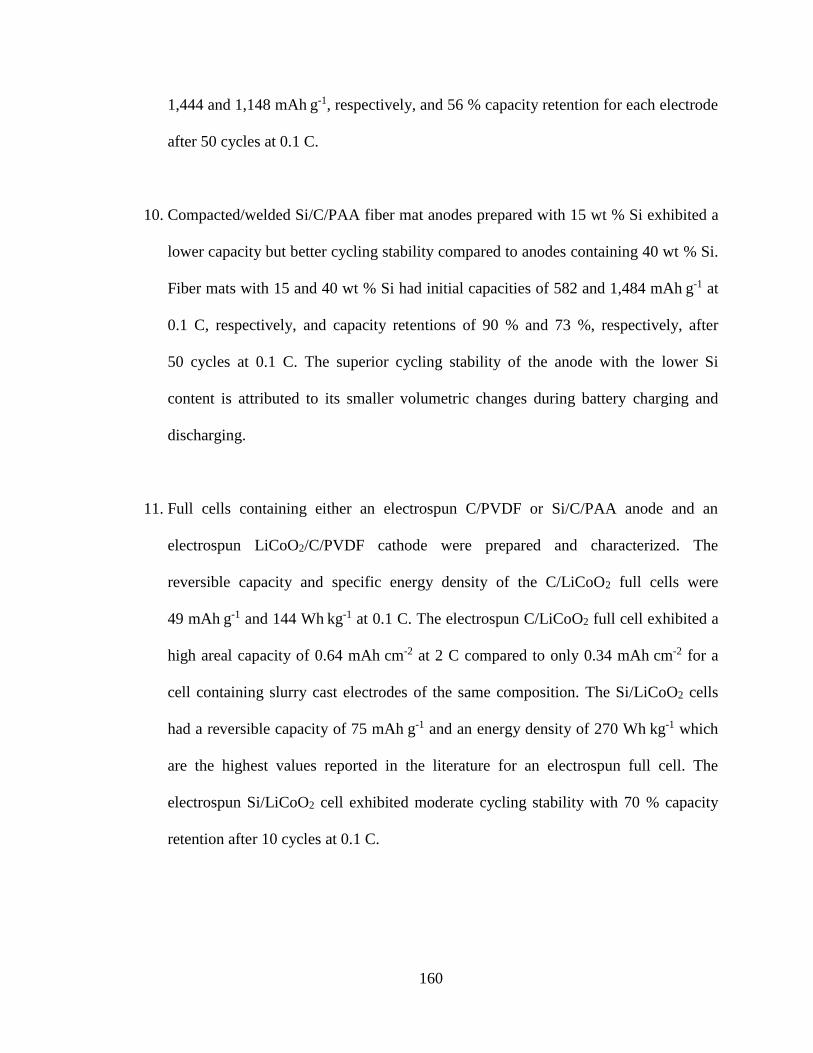
160
1,444 and 1,148 mAh g-1, respectively, and 56 % capacity retention for each electrode
after 50 cycles at 0.1 C.
10. Compacted/welded Si/C/PAA fiber mat anodes prepared with 15 wt % Si exhibited a
lower capacity but better cycling stability compared to anodes containing 40 wt % Si.
Fiber mats with 15 and 40 wt % Si had initial capacities of 582 and 1,484 mAh g-1 at
0.1 C, respectively, and capacity retentions of 90 % and 73 %, respectively, after
50 cycles at 0.1 C. The superior cycling stability of the anode with the lower Si
content is attributed to its smaller volumetric changes during battery charging and
discharging.
11. Full cells containing either an electrospun C/PVDF or Si/C/PAA anode and an
electrospun LiCoO2/C/PVDF cathode were prepared and characterized. The
reversible capacity and specific energy density of the C/LiCoO2 full cells were
49 mAh g-1 and 144 Wh kg-1 at 0.1 C. The electrospun C/LiCoO2 full cell exhibited a
high areal capacity of 0.64 mAh cm-2 at 2 C compared to only 0.34 mAh cm-2 for a
cell containing slurry cast electrodes of the same composition. The Si/LiCoO2 cells
had a reversible capacity of 75 mAh g-1 and an energy density of 270 Wh kg-1 which
are the highest values reported in the literature for an electrospun full cell. The
electrospun Si/LiCoO2 cell exhibited moderate cycling stability with 70 % capacity
retention after 10 cycles at 0.1 C.
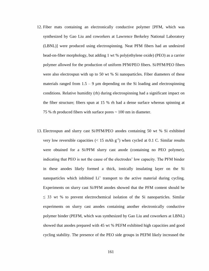
161
12. Fiber mats containing an electronically conductive polymer [PFM, which was
synthesized by Gao Liu and coworkers at Lawrence Berkeley National Laboratory
(LBNL)] were produced using electrospinning. Neat PFM fibers had an undesired
bead-on-fiber morphology, but adding 1 wt % poly(ethylene oxide) (PEO) as a carrier
polymer allowed for the production of uniform PFM/PEO fibers. Si/PFM/PEO fibers
were also electrospun with up to 50 wt % Si nanoparticles. Fiber diameters of these
materials ranged from 1.5 – 9 µm depending on the Si loading and electrospinning
conditions. Relative humidity (rh) during electrospinning had a significant impact on
the fiber structure; fibers spun at 15 % rh had a dense surface whereas spinning at
75 % rh produced fibers with surface pores ~ 100 nm in diameter.
13. Electrospun and slurry cast Si/PFM/PEO anodes containing 50 wt % Si exhibited
very low reversible capacities (< 15 mAh g-1) when cycled at 0.1 C. Similar results
were obtained for a Si/PFM slurry cast anode (containing no PEO polymer),
indicating that PEO is not the cause of the electrodes’ low capacity. The PFM binder
in these anodes likely formed a thick, ionically insulating layer on the Si
nanoparticles which inhibited Li+ transport to the active material during cycling.
Experiments on slurry cast Si/PFM anodes showed that the PFM content should be
≤ 33 wt % to prevent electrochemical isolation of the Si nanoparticles. Similar
experiments on slurry cast anodes containing another electronically conductive
polymer binder (PEFM, which was synthesized by Gao Liu and coworkers at LBNL)
showed that anodes prepared with 45 wt % PEFM exhibited high capacities and good
cycling stability. The presence of the PEO side groups in PEFM likely increased the

162
binder’s electrolyte uptake which allowed Si/PEFM slurry cast anodes to maintain
good electrochemical performance at higher binder contents.

163
CHAPTER VIII
CONCLUSIONS
1. Particle/polymer electrospinning is a robust platform which can be used to prepare a
wide range of fiber mat Li-ion battery (LIB) electrodes with high capacities at fast
charge/discharge rates. The rate capabilities of electrospun particle/polymer fiber
mats are insensitive of the electrode’s active material and polymer binder. As shown
in Appendix B, electrospun TiO2/C/PAA anodes, C/PVDF anodes, and
LiCoO2/C/PVDF cathodes all retained ~ 67 % of their 0.1 C capacity at a 2 C
charge/discharge rate.
2. The cycling stability of particle/polymer fiber mat electrodes containing active
materials which undergo large volumetric changes during lithiation/delithiation
(e.g., Si) can be significantly improved by welding interfiber contacts throughout the
mat. The improved interfiber connectivity of welded fiber mats stabilizes the
electrode structure during battery operation. In comparison, fiber mats containing
active materials which experience small volumetric changes (e.g., TiO2, C, and
LiCoO2) do not require welded interfiber contacts to achieve good cycling stability.
3. The thickness and fiber volume fraction of electrospun particle/polymer fiber mats
must be optimized to meet the energy and power density requirements of a given
application. For fiber mats of a specific fiber volume fraction, the areal capacity at

164
slow charge/discharge rates (e.g., 0.1 C) can increased by utilizing thicker electrodes,
but very thick mats (e.g., > 500 µm) exhibit worse rate capabilities due to increased
Li+ transport distances throughout the electrode. To improve the rate capabilities of
these thick electrodes, the mat’s fiber volume fraction should be decreased. However,
reducing the fiber volume fraction results in lower volumetric capacity. Thus in
general, mat thickness and fiber volume fraction must both be optimized for a given
application.
4. The meso- and macrostructure of LIB electrodes must be optimized to achieve high
capacities at fast charge/discharge rates. Whereas conventional electrode fabrication
techniques (e.g., slurry casting) provide little to no control over the pore structure
throughout the electrode, electrospun particle/polymer fiber mats contain intra- and
interfiber porosity where pore sizes range from a few nm to several µm. The
hierarchical design allows rapid Li+ transport throughout the electrode during battery
operation and thus superior performance at high C-rates compared to conventional
slurry cast electrodes.

165
CHAPTER IX
SUGGESTIONS FOR FUTURE WORK
1. The electrospun Si/C/PAA fiber mat anodes discussed in Chapter VI were prepared
with Si/C/PAA weight ratios of 40/25/35 and 15/50/35. Electrodes with different
amounts of Si, C, and PAA should be prepared and tested in coin cells to better
understand how electrode composition affects the electrochemical performance of
these materials.
2. Si/C/PAA fiber mat anodes should be prepared with a fiber volume fraction
~ 0.80 and thicknesses of at least 200 µm to achieve an areal capacity ~ 14 mAh cm-2.
The cycling performance of these electrodes should be evaluated over at 500 cycles at
charge/discharge rates ranging from 0.1 – 5 C.
3. To prevent the electrochemical isolation of Si nanoparticles in electrospun anodes
prepared with electronically conductive polymer binders (e.g., PFM and PEFM), ink
compositions and electrospinning conditions to form Si/PFM and Si/PEFM fiber mats
containing at least 67 wt % Si and 55 wt % Si, respectively, should be identified. The
electrochemical performance of these electrospun electrodes should be compared to
that of slurry cast anodes of the same compositions. In these studies, various carrier
polymers should also be investigated including, poly(ethylene oxide) (PEO) and
poly(vinylpyrrolidone) (PVP).

166
4. Electrospun mats containing etched Si nanowires (where the SiOx passive layer is
either partially or fully removed) should be prepared and characterized. The effect of
the SiOx layer on reversible capacity and cycling stability of these electrodes should
be determined, and the performance of electrospun Si/C/PAA fiber mats containing
either Si nanoparticles or Si nanowires with comparable SiOx layer thicknesses
should be compared.
5. Chapter IV describes the fabrication and characterization of electrospun fiber mat
C/PVDF anodes prepared with Vulcan XC-72R carbon powder. The charge/discharge
curves collected for these anodes had sloping profiles over 0.015 – 1.5 V vs. Li/Li+
due to the non-graphitic nature of the carbon particles. In comparison, typical graphite
anodes have a flat potential profile which is desired for some applications where
battery voltage should remain relatively constant during discharging. Thus,
particle/polymer electrospinning should be used to prepare graphitic carbon nanofiber
mat anodes, and these materials should be characterized in half cells and full cells.
6. In Chapters III – VI, the capacities of electrospun particle/polymer fiber mat
electrodes were normalized with respect to the total electrode mass and volume. For
commercial battery applications, the mass and volume of other cell components
(e.g., current collectors, separators, electrolyte, and cell packaging) must also be
considered. Future studies should account for these inactive components to evaluate
the cell-level energy density of batteries containing electrospun anodes and cathodes.

167
7. The performance of electrospun particle/polymer fiber mat electrodes should be
evaluated in coin cells containing different electrolyte formulations (e.g., glymes and
ionic liquids) which have wider electrochemical stability windows compared to
conventional electrolytes containing liquid organic carbonates. These studies should
focus on reducing or eliminating irreversible Li consumption due to formation of a
solid-electrolyte interphase (SEI) layer.
8. This dissertation explored electrospun Li-ion battery (LIB) anodes and cathodes
where the average fiber diameter in the mats was on the order of 1 µm. Ink
composition and electrospinning conditions should be adjusted to change the average
fiber diameter of the electrodes, and the effect of fiber diameter on LIB performance
in half cells and full cells should be evaluated.
9. Particle/polymer nanofiber mat anodes and cathodes with different porosities,
thicknesses, and active material loadings should be prepared and evaluated. Such
experiments should be used to optimize anode and cathode designs for use at
0.1 – 5 C.
10. Sulfur-based fiber mat cathodes should be prepared by: (i) electrospinning
sulfur-infiltrated carbon particles with a polymer binder and/or (ii) infiltrating sulfur
into an electrospun carbon/polymer fiber mat. The effects of different carbon particles
and polymer binders on the reversible capacity, polysulfide dissolution, and cycling
stability of these sulfur cathodes in half cells and full cells should be evaluated.
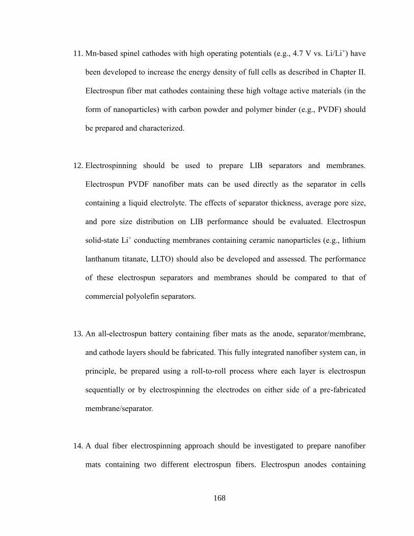
168
11. Mn-based spinel cathodes with high operating potentials (e.g., 4.7 V vs. Li/Li+) have
been developed to increase the energy density of full cells as described in Chapter II.
Electrospun fiber mat cathodes containing these high voltage active materials (in the
form of nanoparticles) with carbon powder and polymer binder (e.g., PVDF) should
be prepared and characterized.
12. Electrospinning should be used to prepare LIB separators and membranes.
Electrospun PVDF nanofiber mats can be used directly as the separator in cells
containing a liquid electrolyte. The effects of separator thickness, average pore size,
and pore size distribution on LIB performance should be evaluated. Electrospun
solid-state Li+ conducting membranes containing ceramic nanoparticles (e.g., lithium
lanthanum titanate, LLTO) should also be developed and assessed. The performance
of these electrospun separators and membranes should be compared to that of
commercial polyolefin separators.
13. An all-electrospun battery containing fiber mats as the anode, separator/membrane,
and cathode layers should be fabricated. This fully integrated nanofiber system can, in
principle, be prepared using a roll-to-roll process where each layer is electrospun
sequentially or by electrospinning the electrodes on either side of a pre-fabricated
membrane/separator.
14. A dual fiber electrospinning approach should be investigated to prepare nanofiber
mats containing two different electrospun fibers. Electrospun anodes containing

169
separate Si/PAA fibers for high lithium capacity and C/PAA fibers for high electronic
conductivity should be prepared where the weight ratio of the two fiber types is
systematically changed. The performance of the dual fiber electrodes should be
compared to that of single fiber mats of the same composition (i.e., mats containing
Si, C, and PAA in the same fiber) to determine how the location of carbon powder
affects cycling stability. Dual fiber mats with varying amounts of electronically
conductive fibers should be prepared to determine the percolation threshold to
achieve complete active material utilization of the Si/PAA fibers. Dual fiber mats
should be prepared with different electrode thicknesses in the range of 50 – 200 µm
and evaluated in half cells and full cells.
15. Core-shell electrospinning should be used to prepare fibers with concentric layers of
anode, separator, and cathode materials. For example, a fiber would contain an anode
core and cathode shell which are separated by a thin, ionically conductive membrane
layer. At one end of the fiber, the anode should be exposed by etching away the
cathode shell and membrane layer such that opposite ends of the fiber represent the
battery’s positive and negative terminals. Multiple fibers should be electronically
wired together to increase the amount of energy that can be stored in the battery. This
envisioned battery architecture has a very high material packing efficiency and would
thus have a high systems-level energy density.
16. Electrospun particle/polymer nanofiber mats should be used to optimize the
electrode/electrolyte interface for energy storage and conversion devices beyond

170
LIBs. Fiber mat electrodes for next-generation battery systems
(e.g., Na-ion, Mg-ion, and Li-air) and supercapacitors should be developed. The
effects of mat thickness and pore structure on the performance of these devices should
be studied.

171
APPENDIX A
SYNTHESIS OF LICOO2 NANOPARTICLES
A.1 Experimental Methods and Results
In addition to the sonochemical synthesis method described in Chapter V, LiCoO2
nanoparticles were prepared using a sol-gel reaction as described in the literature.[1-3] For
the sol-gel method, an aqueous solution containing a 1/1/2 molar ratio of
LiNO3/CoN2O4·6 H2O/poly(acrylic acid) (Mw = 1,800 Da) was magnetically stirred and
evaporated at 80 °C overnight until a thick, pink gel was obtained. The resulting gel was
then heated in air for 1 h at 300 °C followed by 1 h at 750 °C. Figures A.1a and A.1b
show scanning electron microscopy (SEM) images of the resulting LiCoO2 powder which
contained primary particles (~ 200 – 500 nm in size) that were fused together. This
sintered structure is undesired for electrospinning since individual particles need to be
dispersed within the fibers. Therefore, LiCoO2 nanoparticles prepared via a sol-gel
method were not further investigated in the present study. In comparison, LiCoO2
nanoparticles prepared using the synthesis method described in Chapter V were well-
separated with diameters ranging from ~ 300 – 1,000 nm as shown in Figures A.1c and
A.1d.

172
Figure A.1. SEM images of LiCoO2 nanoparticles synthesized using a (a,b) sol-gel
method and (c,d) the sonochemical method described in Chapter V.

173
A.2 References
[1] Y.-K. Sun, I.-H. Oh, S.-A. Hong, J. Mater. Sci. 1996, 31, 3617.
[2] I.-H. Oh, S.-A. Hong, Y.-K. Sun, J. Mater. Sci. 1997, 32, 3177.
[3] Z. S. Peng, C. R. Wan, C. Y. Jiang, J. Power Sources 1998, 72, 215.

174
APPENDIX B
RATE CAPABILITIES OF TIO2/C/PAA, C/PVDF, and LICOO2/C/PVDF FIBER MAT
ELECTRODES
The performance of electrospun TiO2/C/PAA anodes, C/PVDF anodes, and
LiCoO2/C/PVDF cathodes were compared in half cells at 0.1 – 2 C. As shown in
Figure B.1, each electrode was prepared with an areal capacity ~ 0.1 mAh cm-2 at 0.1 C,
and the electrospun anodes and cathodes exhibited similar performance at higher C-rates
with capacity retentions of 67 ± 4 % at 2 C. These results demonstrate that
particle/polymer electrospinning can be used to prepare a wide range of electrodes with
good performance up to 2 C where the rate capabilities are insensitive to the active
material and polymer binder used.

175
Figure B.1. (a) Areal capacity and (b) capacity retention of electrospun fiber mat
TiO2/C/PAA, C/PVDF, and LiCoO2/C/PVDF electrodes at 0.1 – 2 C in half cells.
Capacity retention in (b) is calculated by normalizing the capacity with respect to the
capacity measured at 0.1 C for each electrode. The electrodes contained TiO2/C/PAA,
C/PVDF, and LiCoO2/C/PVDF in a 40/25/35, 65/35, and 70/10/20 weight ratio,
respectively.
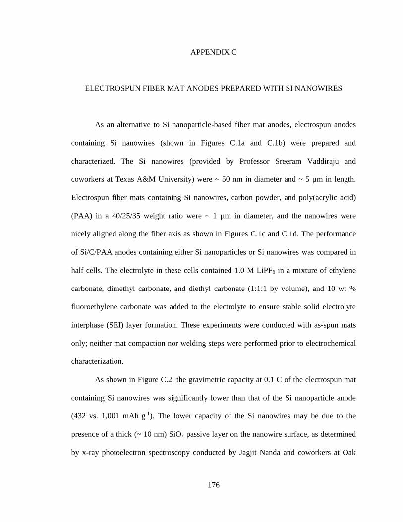
176
APPENDIX C
ELECTROSPUN FIBER MAT ANODES PREPARED WITH SI NANOWIRES
As an alternative to Si nanoparticle-based fiber mat anodes, electrospun anodes
containing Si nanowires (shown in Figures C.1a and C.1b) were prepared and
characterized. The Si nanowires (provided by Professor Sreeram Vaddiraju and
coworkers at Texas A&M University) were ~ 50 nm in diameter and ~ 5 µm in length.
Electrospun fiber mats containing Si nanowires, carbon powder, and poly(acrylic acid)
(PAA) in a 40/25/35 weight ratio were ~ 1 µm in diameter, and the nanowires were
nicely aligned along the fiber axis as shown in Figures C.1c and C.1d. The performance
of Si/C/PAA anodes containing either Si nanoparticles or Si nanowires was compared in
half cells. The electrolyte in these cells contained 1.0 M LiPF6 in a mixture of ethylene
carbonate, dimethyl carbonate, and diethyl carbonate (1:1:1 by volume), and 10 wt %
fluoroethylene carbonate was added to the electrolyte to ensure stable solid electrolyte
interphase (SEI) layer formation. These experiments were conducted with as-spun mats
only; neither mat compaction nor welding steps were performed prior to electrochemical
characterization.
As shown in Figure C.2, the gravimetric capacity at 0.1 C of the electrospun mat
containing Si nanowires was significantly lower than that of the Si nanoparticle anode
(432 vs. 1,001 mAh g-1). The lower capacity of the Si nanowires may be due to the
presence of a thick (~ 10 nm) SiOx passive layer on the nanowire surface, as determined
by x-ray photoelectron spectroscopy conducted by Jagjit Nanda and coworkers at Oak

177
Ridge National Laboratory (results not shown). Despite its lower capacity, the Si
nanowire anode exhibited superior cycling stability, retaining 68 % of its initial capacity
after 50 cycles, as compared to only 21 % capacity retention for the nanofiber anode
containing Si nanoparticles. The superior cycling stability of the anode containing Si
nanowires could be attributed to one or more of the following: (i) improved fiber strength
due to the presence of aligned Si nanowires along the fiber axis, (ii) anisotropic
volumetric changes during lithiation/delithiation due to the unique nanowire aspect ratio,
and/or (iii) the lower capacity and thus less severe volumetric changes during cycling of
the Si nanowires.
Figure C.1. SEM images of (a,b) Si nanowires and (c,d) electrospun nanofibers
containing Si nanowires, carbon black, and PAA in a 40/25/35 weight ratio.

178
Figure C.2. Electrochemical performance of as-spun Si/C/PAA nanofiber mats where the
Si active material is either in the form of nanowires or nanoparticles. (a) Gravimetric
capacity and (b) capacity retention over 50 cycles at 0.1 C.