battery compartment and device design...
TRANSCRIPT

Important Notice This document contains general information regarding design considerations.
©Energizer Holdings, Inc. - Contents herein do not constitute a warranty.
Battery Compartment and Device
Design Considerations
1 of 15

Important Notice This document contains general information regarding design considerations.
©Energizer Holdings, Inc. - Contents herein do not constitute a warranty.
Closed Circuit Voltage (incoming inspection test)
2 of 15
The open circuit voltage reading, no load applied, of a battery or pack can be misleading. A closed circuit voltage test, battery under load, is used to create a voltage drop in the battery. The amount of the voltage drop is a good indication as to the condition of the battery.
Multiply the number of cells in the series pack by the load resistance.
Multiply the number of cells in the pack by the “minimum voltage per cell to pass”.
Example: 4 E91 series battery pack
4 x 10 W = 40 Load
4 X 1.4 volts = 5.6 minimum pack voltage to pass
Load
Duration (Seconds)
Min. Voltage per cell to Pass
E95 10 W 2 to 5 1.4
E93 10 W 2 to 5 1.35
E92 43 W 2 to 5 1.35
E91 10 W 2 to 5 1.4
L91 3.9 W 2 to 5 1.4

Important Notice This document contains general information regarding design considerations.
©Energizer Holdings, Inc. - Contents herein do not constitute a warranty.
Battery Contact Considerations
• Dimensional: ANSI and IEC industry standard dimensions should be used when designing a battery compartment to avoid battery fit problems.
• Mechanical Properties: The material must have enough ductility, should be strong to avoid deformation, should not relax over time, and should resist wear.
• Electrical Conductivity: The better the conductivity of the connector the lower the contact resistance will be.
• Environmental Stability: It is particular important that the contact material does not corrode, or cause corrosion of the materials that it is in contact with.
• Cost: No material is perfect. There are often trade-offs between the aforementioned material considerations.
• Practical solutions often involve coating a substrate to get an optimum combination of properties. That is, the coating primarily provides the electrical and environmental properties; whereas, the substrate gives most of the mechanical properties, with a possible cost reduction if a relatively cheap material is used.
Plating and Substrates
1. Gold Plating - Provides the most reliable metal-to-metal contact under all environmental conditions.
2. Nickel (Solid) - Provides excellent resistance to environmental corrosion and is second only to gold plating as a contact material. Solid nickel can be easily drawn or formed.
3. Nickel Clad Stainless - Performs almost as well as solid nickel with excellent resistance to corrosion.
4. Nickel-Plated Stainless - A widely used material. Non-plated stainless steel is not recommended due to the adverse impact of passive films, which develop on the surface and result in poor electrical contact.
5. lnconnel Alloy - Provides good electrical conductivity and good corrosion resistance. However, soldering may be difficult unless an active flux is used.
3 of 15
Important Notice This document contains general information regarding design considerations.
©Energizer Holdings, Inc. - Contents herein do not constitute a warranty.
Battery Contact Considerations (plating and substrates – continued)
6. Nickel-Plated Cold-Rolled Steel - An economical contact material that provides a good contact surface for welding and soldering.
• The connectors used with conventional cylindrical cells are primarily Ni-plated
• The Ni-plating must be adherent, continuous, non-porous, and resistant to wear. The suggested plating thickness is 200 micro-inches.
• Avoid Sn-plating for connectors due to possible galvanic corrosion and fretting wear/corrosion.
4 of 15

Important Notice This document contains general information regarding design considerations.
©Energizer Holdings, Inc. - Contents herein do not constitute a warranty. 5 of 15
Cutoff Voltage (recommended cutoff voltage for alkaline batteries)
• Please contact Energizer for recommendations based on your application or device. Click here

Important Notice This document contains general information regarding design considerations.
©Energizer Holdings, Inc. - Contents herein do not constitute a warranty.
Hydrogen Generation (alkaline batteries)
• Hydrogen gas is a byproduct of the chemical reaction in all alkaline batteries. Under normal usage, this gas production is very low. However, in abusive conditions, (i.e. charging or shorting) high levels of hydrogen can be produced.
• In devices that use a tightly sealed battery case (i.e. diving lights), the hydrogen gas can mix with air to create an explosive atmosphere.
• The amount of hydrogen generated is dependent on several factors including the number of batteries and their size.
• Hydrogen gas generation in water proof battery compartments needs to be addressed as a potential safety issue to prevent the accumulation of dangerous levels of hydrogen gas within the device.
1. Hydrogen catalyst pellets (commonly referred
to as “getters”) can be used to react the excess hydrogen with oxygen to form water vapor.
2. Gas permeable venting membranes can be used to allow the escape of hydrogen gas while still keeping the battery case watertight.
Hydrogen Catalyst Pellet
6 of 15

Important Notice This document contains general information regarding design considerations.
©Energizer Holdings, Inc. - Contents herein do not constitute a warranty.
Industry Standards (ANSI - IEC)
• The physical size of batteries is regulated by the American National Standards Institute (ANSI) and the International Electrotechnical Commission (IEC).
• These organizations set standard dimensions with tolerances for maximum and minimum dimensions for each battery size.
• Energizer batteries meet safety standards set by ANSI and IEC.
• It is important that device manufacturers also design to this specification which insures a proper fit and function between the battery and the device.
A
B
G
C
F
(+)
(-)
P
0.25 M P
7 of 15

Important Notice This document contains general information regarding design considerations.
©Energizer Holdings, Inc. - Contents herein do not constitute a warranty.
Battery Interconnections (ANSI - IEC)
There are three basic methods for electrically connecting batteries to power a device:
1. Pressure contacts is the most common method for connecting to
batteries. The contact force should be one half to two pounds force.
2. Soldering to batteries can cause problems due to the intense heat that needs to be applied to the battery during this process. Energizer does not recommend this method.
3. Resistance welding is preferred to soldering due to the significantly reduced battery heating. The weld is controlled by a combination of heat, time and pressure.
8 of 15

Important Notice This document contains general information regarding design considerations.
©Energizer Holdings, Inc. - Contents herein do not constitute a warranty.
Battery Internal Resistance
• The internal resistance (IR) of a battery is defined as the opposition to the flow of current within the battery.
• There are two basic components that impact the internal resistance of a battery; they are electronic resistance and ionic resistance. The electronic resistance plus the ionic resistance will be referred to as the total effective resistance.
• The electronic resistance encompasses the resistivity of the actual materials such as the metal covers and internal components; as well as, how well these materials make contact with each other.
• Ionic resistance is the resistance to current flow within the battery due to electrochemical factors which include electrolyte conductivity, ion mobility, and electrode surface area.
Calculation – dual pulse method
• This test involves placing a battery on a low background drain, allowing it to stabilize, and then pulsing it with a heavier load for 100 milliseconds.
• Using Ohm’s Law, V=IxR, the total effective resistance is calculated by dividing the change in voltage by the change in current: R=ΔV / ΔI.
Total Effective Resistance
Dual Pulse Method (5mA/505mA)
1.35
1.40
1.45
1.50
1.55
0 20 40 60 80 100 120 140
Time (Milliseconds)
Vo
ltag
e
Heavy Drain (505 mA)
Delta VoltageStabilizing
Drain (5 mA)
9 of 15
Important Notice This document contains general information regarding design considerations.
©Energizer Holdings, Inc. - Contents herein do not constitute a warranty.
Battery Reversal Protection
• When a battery without reversal protection is installed in reverse in a device (e.g. boom box) with 3 or more other batteries and the device is turned on, the device will likely still run (e.g. play music).
• While the device is running, the incorrectly-installed battery will be charged by the remaining batteries.
• Alkaline batteries are not designed to be charged and could potentially vent under these conditions to minimize internal pressures. When a battery vents, there is a strong possibility for leakage.
Implementation
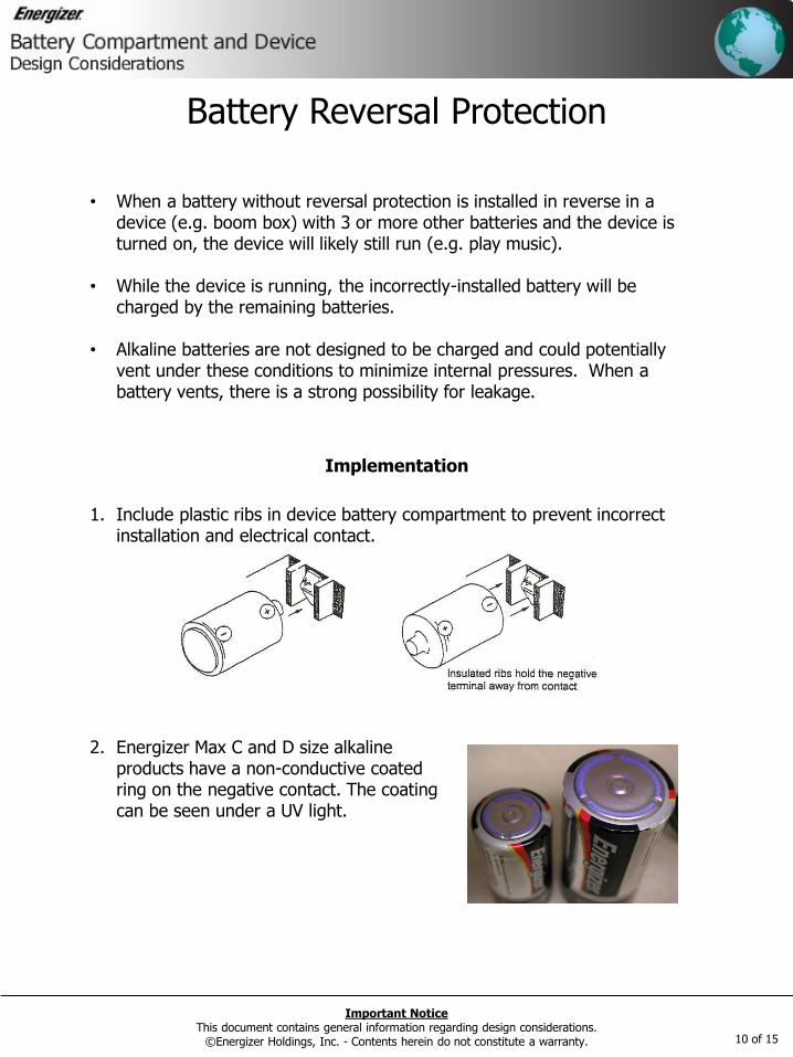
1. Include plastic ribs in device battery compartment to prevent incorrect installation and electrical contact.
2. Energizer Max C and D size alkaline products have a non-conductive coated ring on the negative contact. The coating can be seen under a UV light.
10 of 15

Important Notice This document contains general information regarding design considerations.
©Energizer Holdings, Inc. - Contents herein do not constitute a warranty.
Series vs. Parallel
11 of 15
Batteries in Series Batteries connected end to end (positive terminal to negative terminal) are said to be connected in series. System Voltage The total voltage of the batteries connected in series will be a sum of the individual battery voltages in the series string. System Capacity The system capacity, measured in mAh, does not increase in a series string compared to an individual battery. Potential Pitfalls Incorrect Installation Reversal protection is recommended to prevent the charging of an incorrectly installed battery in a string of three or more. For information on reversal protection see the design considerations page: http://data.energizer.com/design_hints/pages/dhints_revprotection.html Deep Discharge Batteries in a series configuration are susceptible to deep discharge. This will occur when a battery is discharged to less than 0.8V. There is an increased potential of internal gassing and subsequent leakage concerns when a battery is deep discharged. A device that uses a single battery that is closely monitored can be discharged down to 0.5V. If the batteries are deep discharged and cannot be disconnected from the load, a maximum drain of 50 μA is recommended to limit internal gassing over time.
Figure 1 - Example of Batteries in Series
Important Notice This document contains general information regarding design considerations.
©Energizer Holdings, Inc. - Contents herein do not constitute a warranty.
Series vs. Parallel
12 of 15
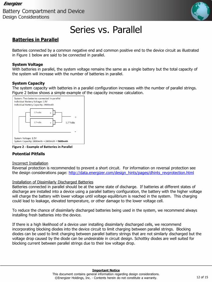
Batteries in Parallel Batteries connected by a common negative end and common positive end to the device circuit as illustrated in Figure 1 below are said to be connected in parallel. System Voltage With batteries in parallel, the system voltage remains the same as a single battery but the total capacity of the system will increase with the number of batteries in parallel. System Capacity The system capacity with batteries in a parallel configuration increases with the number of parallel strings. Figure 2 below shows a simple example of the capacity increase calculation. Potential Pitfalls Incorrect Installation Reversal protection is recommended to prevent a short circuit. For information on reversal protection see the design considerations page: http://data.energizer.com/design_hints/pages/dhints_revprotection.html Installation of Dissimilarly Discharged Batteries Batteries connected in parallel should be at the same state of discharge. If batteries at different states of discharge are installed into a device using a parallel battery configuration, the battery with the higher voltage will charge the battery with lower voltage until voltage equilibrium is reached in the system. This charging could lead to leakage, elevated temperature, or other damage to the lower voltage cell. To reduce the chance of dissimilarly discharged batteries being used in the system, we recommend always installing fresh batteries into the device. If there is a high likelihood of a device user installing dissimilarly discharged cells, we recommend incorporating blocking diodes into the device circuit to limit charging between parallel strings. Blocking diodes can be used to limit charging between parallel battery strings that are not similarly discharged but the voltage drop caused by the diode can be undesirable in circuit design. Schottky diodes are well suited for blocking current between parallel strings due to their low voltage drop.
Figure 2 - Example of Batteries in Parallel

Important Notice This document contains general information regarding design considerations.
©Energizer Holdings, Inc. - Contents herein do not constitute a warranty.
Series vs. Parallel
13 of 15
Series/Parallel Combination
System Voltage In a series/parallel configuration, two or more batteries are connected in series and then placed in parallel with additional series strings. The voltage of this system is additive in the series string. System Capacity The capacity of the battery system increases by the number of parallel strings.
For example, with the series / parallel configuration shown in Figure 3 using 1.5V 2800 mAh batteries, the output would be 3.0V with a capacity of 5600 mAh. Potential Pitfalls Incorrect Installation Reversal protection is recommended to prevent charging of one battery and shorting of other incorrectly installed batteries. For information on reversal protection see the design considerations page: http://data.energizer.com/design_hints/pages/dhints_revprotection.html Installation of Dissimilarly Discharged Batteries Batteries connected in parallel should be at the same state of discharge. If batteries at different states of discharge are installed into a device using a parallel battery configuration, the battery with the higher voltage will charge the battery with lower voltage until voltage equilibrium is reached in the system. This charging could lead to leakage, elevated temperature, or other damage to the lower voltage cell. To reduce the chance of dissimilarly discharged batteries being used in the system, we recommend always installing fresh batteries into the device. If there is a high likelihood of a device user installing dissimilarly discharged cells, we recommend incorporating blocking diodes into the device circuit to limit charging between parallel strings. Blocking diodes can be used to limit charging between parallel battery strings that are not similarly discharged but the voltage drop caused by the diode can be undesirable in circuit design. Schottky diodes are well suited for blocking current between parallel strings due to their low voltage drop.
Figure 3 - Example of Batteries Connected in a Series/Parallel String
Important Notice This document contains general information regarding design considerations.
©Energizer Holdings, Inc. - Contents herein do not constitute a warranty.
Battery Sterilization (configurations)
• Energizer recommends the use of either Gamma Ray or ethylene oxide (EtO) for battery sterilization. Zinc Air batteries should only be sterilized using the gamma ray method and the level needs to be kept below 50 kGy.
• In general, primary batteries need to be kept within a temperature range
of approximately 0ºC to 55ºC during the sterilization process in order to preserve performance and reliability. This eliminates autoclaving as a recommended method for battery sterilization.
• Gamma Ray and EtO methods have been used for the sterilization of batteries by the medical field for many years.
14 of 15

Important Notice This document contains general information regarding design considerations.
©Energizer Holdings, Inc. - Contents herein do not constitute a warranty.
Sub FEP Drains (continued)
• Voltage regulators and DC/DC converters can place significant drains on batteries when operated outside their normal parameters when batteries will no longer operate a device
• The “off-state” drains can jump from microamps to milliamps when a LDO (low drop out) linear regulator drops out or DC/DC stops switching.
• Include a FET (field effect transistor) as a means of controlling the battery drain.
• If complete removal of load from the battery source is not possible, Energizer allows a maximum discharge current of 35 microamps.
15 of 15