battery devices short form catalog - littelfuse · strap and disc devices, low rho smd devices and...
TRANSCRIPT
Littelfuse.com ©2016 Littelfuse, Inc.
SHORT FORM CATALOG
Littelfuse battery protection products offer engineers enhanced design flexibility and the ability to meet regulatory requirements.
BATTERY DEVICES
Littelfuse.com ©2016 Littelfuse, Inc.
2
Battery Devices
OUR EXPERTISELittelfuse PolySwitch Circuit Protection began almost 40 years ago, pioneering the field
of resettable PPTC (polymeric positive temperature coefficient) technology with our
PolySwitch product line. Today our extensive product portfolio reflects our expertise
in developing different material platforms that help designers create safe and reliable
applications.
BATTERY PROTECTION PRODUCTS Our devices for battery protection include hybrid MHP-TA devices, PolySwitch PPTC
strap and disc devices, low rho SMD devices and surface-mount fuses. By drawing upon
our long history in materials science and customer knowledge, our products respond
to evolving battery technologies to meet specific design requirements. As a result, our
battery protection products offer engineers enhanced design flexibility and the ability
meet regulatory requirements – all while helping them achieve energy-saving, space- and
cost-effective designs.
In choosing the appropriate battery circuit protection device, designers should consider
the requirements of the end use application, cell chemistry and cell geometry, in addition
to the relevant electrical specifications of each application.
BATTERY PACKS FOR:• Mobile Phone and Smart Phones
• Tablet PCs
• Ultra-thin Notebooks
• Mobile Radios
• Digital Cameras
• Portable Media Players
CHARGE LINES FOR:• Power Tools
Circuit Protection Devices for Battery Application
Typical Battery Applications
Littelfuse.com ©2016 Littelfuse, Inc.
3
Battery Devices
Protection Application
Cell Capacity
DeviceRecommendation
Typical Hold Current
@ 25°C
Installation Method
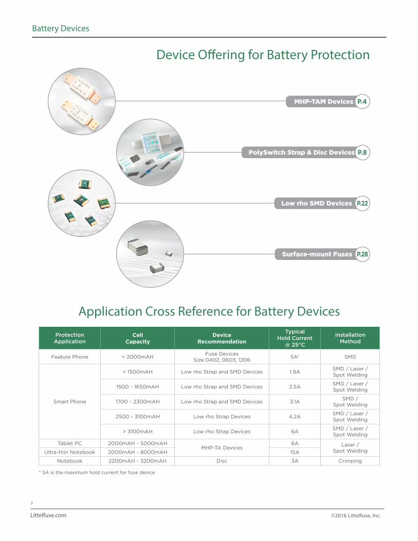
Feature Phone < 2000mAHFuse Devices
Size 0402, 0603, 12065A* SMD
Smart Phone
< 1500mAH Low rho Strap and SMD Devices 1.9ASMD / Laser /Spot Welding
1500 ~ 1650mAH Low rho Strap and SMD Devices 2.5ASMD / Laser /Spot Welding
1700 ~ 2300mAH Low rho Strap and SMD Devices 3.1ASMD /
Spot Welding
2500 ~ 3100mAH Low rho Strap Devices 4.2ASMD / Laser /Spot Welding
> 3100mAH Low rho Strap Devices 6ASMD / Laser /Spot Welding
Tablet PC 2000mAH ~ 5000mAHMHP-TA Devices
6A Laser / Spot WeldingUltra-thin Notebook 2000mAH ~ 8000mAH 15A
Notebook 2200mAH ~ 3200mAH Disc 3A Crimping
* 5A is the maximum hold current for fuse device
PolySwitch Strap & Disc Devices
MHP-TAM Devices
P.8
Low rho SMD Devices P.22
Surface-mount Fuses P.28
Application Cross Reference for Battery Devices
Device Offering for Battery Protection
P.4
Littelfuse.com ©2016 Littelfuse, Inc.
4
Battery Devices
Benefits• Capable of handling voltages and battery charge rates
found in high-capacity LiP and prismatic cells used in cutting-edge applications
• Helps provide resettable and accurate overtemperature protection
• Compact size and thin form factor facilitates circuit protection in ultra-thin battery pack designs
• Customization of welding leads available to facilitate design
Features• Two levels of hold current:
- Low current (nominal 6A hold current @25°C) - High current (nominal 15A hold current @25°C)
• Multiple temperature ratings - (72°C, 77°C, 82°C, 85°C, 90°C)
• Compact size (L:5.8mm x W:3.85mm x H:1.15mm)
Electrical Characteristics for MHP-TAM Devices (Typical)
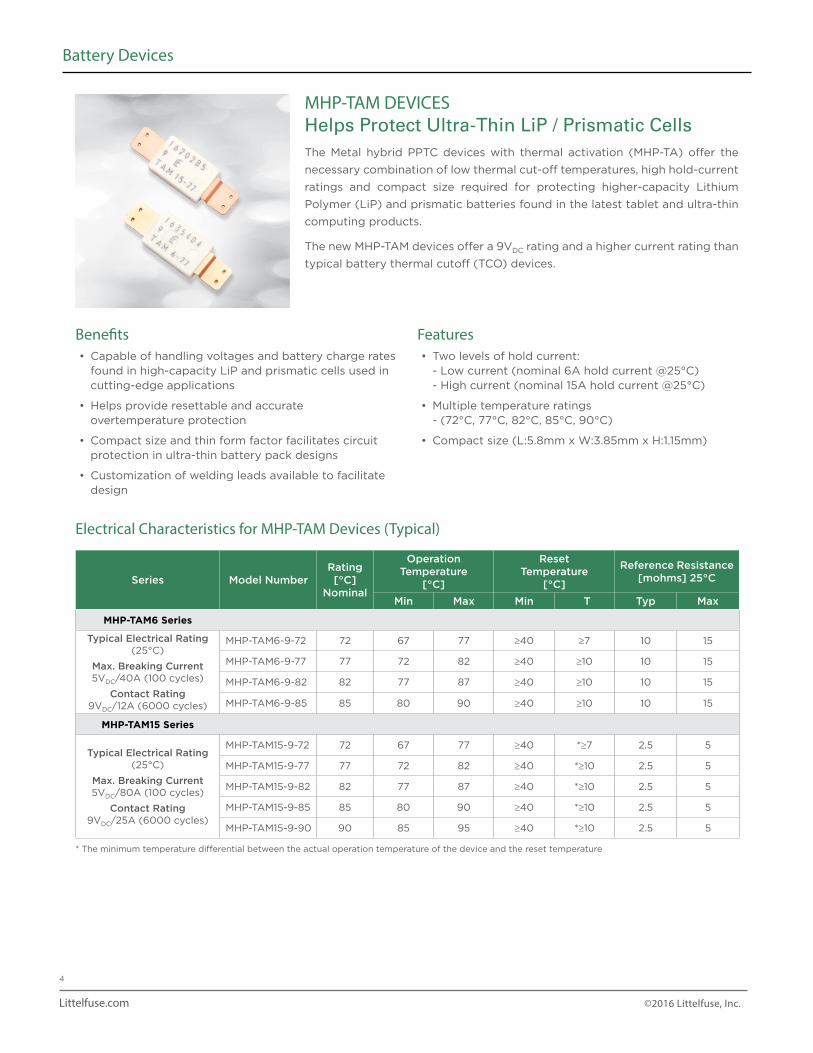
MHP-TAM DEVICESHelps Protect Ultra-Thin LiP / Prismatic CellsThe Metal hybrid PPTC devices with thermal activation (MHP-TA) offer the
necessary combination of low thermal cut-off temperatures, high hold-current
ratings and compact size required for protecting higher-capacity Lithium
Polymer (LiP) and prismatic batteries found in the latest tablet and ultra-thin
computing products.
The new MHP-TAM devices offer a 9VDC rating and a higher current rating than
typical battery thermal cutoff (TCO) devices.
Series Model NumberRating[°C]
Nominal
Operation Temperature
[°C]
Reset Temperature
[°C]
Reference Resistance[mohms] 25°C
Min Max Min T Typ Max
MHP-TAM6 Series
Typical Electrical Rating (25°C)
Max. Breaking Current5VDC/40A (100 cycles)
Contact Rating9VDC/12A (6000 cycles)
MHP-TAM6-9-72 72 67 77 ≥40 ≥7 10 15
MHP-TAM6-9-77 77 72 82 ≥40 ≥10 10 15
MHP-TAM6-9-82 82 77 87 ≥40 ≥10 10 15
MHP-TAM6-9-85 85 80 90 ≥40 ≥10 10 15
MHP-TAM15 Series
Typical Electrical Rating (25°C)
Max. Breaking Current5VDC/80A (100 cycles)
Contact Rating9VDC/25A (6000 cycles)
MHP-TAM15-9-72 72 67 77 ≥40 *≥7 2.5 5
MHP-TAM15-9-77 77 72 82 ≥40 *≥10 2.5 5
MHP-TAM15-9-82 82 77 87 ≥40 *≥10 2.5 5
MHP-TAM15-9-85 85 80 90 ≥40 *≥10 2.5 5
MHP-TAM15-9-90 90 85 95 ≥40 *≥10 2.5 5
* The minimum temperature differential between the actual operation temperature of the device and the reset temperature
Littelfuse.com ©2016 Littelfuse, Inc.
5
Battery Devices
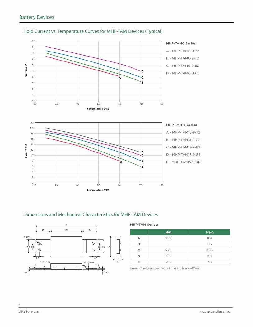
Hold Current vs. Temperature Curves for MHP-TAM Devices (Typical)
10
9
8
7
6
5
4
3
2
1
020 30 40 50 60 70 80
Cu
rre
nt
(A)
Temperature (°C)
A
B
C
D
22
20
18
16
14
12
10
8
6
4
2
0403020 50 60 70 80
Cu
rre
nt
(A)
Temperature (°C)
A
B
C
DE
MHP-TAM6 Series
A - MHP-TAM6-9-72
B - MHP-TAM6-9-77
C - MHP-TAM6-9-82
D - MHP-TAM6-9-85
MHP-TAM15 Series
A - MHP-TAM15-9-72
B - MHP-TAM15-9-77
C - MHP-TAM15-9-82
D - MHP-TAM15-9-85
E - MHP-TAM15-9-90
Dimensions and Mechanical Characteristics for MHP-TAM Devices
D E
C
B
A
5.8
0.10.10.10�0.010.10�0.01
(0.2)(0.2)
2.5
0.70.7
2.5
F
G
0.1
5
ED1.2
1.31.3
AB C
1.2 1.2
4-ø0.4
Min Max
A 10.9 11.4
B - 1.15
C 3.75 3.85
D 2.6 2.8
E 2.6 2.8
Unless otherwise specified, all tolerances are ±0.1mm.
MHP-TAM Series:
Littelfuse.com ©2016 Littelfuse, Inc.
6
Battery Devices
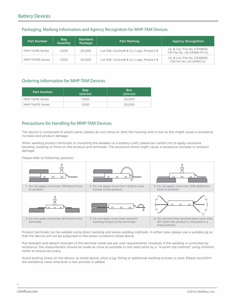
Packaging, Marking Information and Agency Recognition for MHP-TAM Devices
Ordering Information for MHP-TAM Devices
Part NumberBag
(pieces)Box
(pieces)
MHP-TAM6 Series 1,000 20,000
MHP-TAM15 Series 1,000 20,000
Precautions for Handling for MHP-TAM Devices
The device is composed of plastic parts, please do not clamp or dent the housing with a tool as this might cause a resistance increase and product damage.
When welding product terminals or mounting the breaker on a battery (cell), please be careful not to apply excessive bending, twisting or force on the product and terminals. The excessive stress might cause a resistance increase or product damage.
Please refer to following cautions:
1. Do not apply more than 10N bend force to product.
2. Do not apply more than 1.5cN/m twist torque to the product.
3. Do not apply more than 20N deflection force to product.
4. Do not apply more than 2N force to the terminals.
5. Do not apply more than 0.6cN/m twisting torque to the terminals.
6. Do not bend the terminal base more than 45° when the product is mounted in a fixed position.
Product terminals can be welded using direct welding and series welding methods. In either case, please use a suitable jig so that the device will not be subjected to the stress conditions listed above.
Pull strength and detach strength of the terminal welds are per user requirements. However, if the welding is controlled by resistance, the measurement should be made as close as possible to the weld point by a “4-point clip method” using milliohm meter to ensure accuracy.
Avoid putting stress on the device, as listed above, when a jig, fitting or additional welding process is used. Please reconfirm the resistance value whenever a new process is added.
45°
45°
45°
45°
45°
45°
45°
45°
45°
45°
45°
45°
45°
45°
45°
45°
45°
45°
45°
45°
45°
45°
45°
45°
Part NumberBag
QuantityStandard Package
Part Marking Agency Recognition
MHP-TAM6 Series 1,000 20,000 Lot ID#, Control# & Co. Logo, Product #UL & cUL File No. E349829; CB File No. US-23966-M1-UL
MHP-TAM15 Series 1,000 20,000 Lot ID#, Control# & Co. Logo, Product #UL & cUL File No. E349829;
CB File No. US-24160-UL
Littelfuse.com ©2016 Littelfuse, Inc.
7
Battery Devices
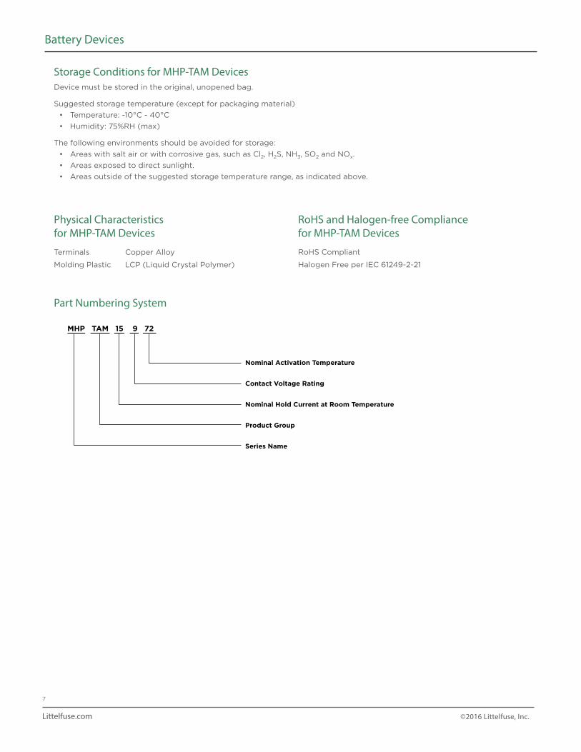
Storage Conditions for MHP-TAM Devices
Physical Characteristics for MHP-TAM Devices
Terminals Copper Alloy
Molding Plastic LCP (Liquid Crystal Polymer)
RoHS and Halogen-free Compliance for MHP-TAM Devices
RoHS Compliant
Halogen Free per IEC 61249-2-21
Device must be stored in the original, unopened bag.
Suggested storage temperature (except for packaging material)
• Temperature: -10°C - 40°C
• Humidity: 75%RH (max)
The following environments should be avoided for storage:
• Areas with salt air or with corrosive gas, such as Cl2, H2S, NH3, SO2 and NOx.
• Areas exposed to direct sunlight.
• Areas outside of the suggested storage temperature range, as indicated above.
Part Numbering System
MHP TAM 15 9 72
Nominal Activation Temperature
Contact Voltage Rating
Nominal Hold Current at Room Temperature
Product Group
Series Name
Littelfuse.com ©2016 Littelfuse, Inc.
8
Battery Devices
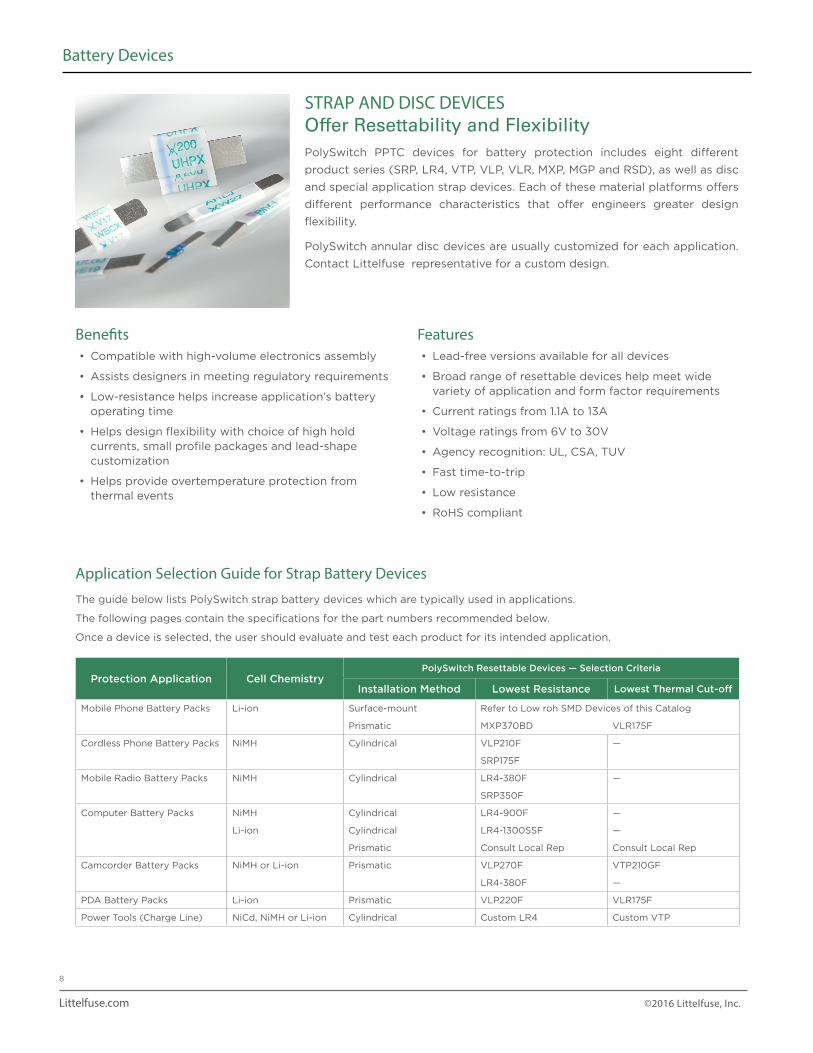
Application Selection Guide for Strap Battery Devices
The guide below lists PolySwitch strap battery devices which are typically used in applications.
The following pages contain the specifications for the part numbers recommended below.
Once a device is selected, the user should evaluate and test each product for its intended application.
Protection Application Cell ChemistryPolySwitch Resettable Devices — Selection Criteria
Installation Method Lowest Resistance Lowest Thermal Cut-off
Mobile Phone Battery Packs Li-ion Surface-mount Refer to Low roh SMD Devices of this Catalog
Prismatic MXP370BD VLR175F
Cordless Phone Battery Packs NiMH Cylindrical VLP210F —
SRP175F
Mobile Radio Battery Packs NiMH Cylindrical LR4-380F —
SRP350F
Computer Battery Packs NiMH Cylindrical LR4-900F —
Li-ion Cylindrical LR4-1300SSF —
Prismatic Consult Local Rep Consult Local Rep
Camcorder Battery Packs NiMH or Li-ion Prismatic VLP270F VTP210GF
LR4-380F —
PDA Battery Packs Li-ion Prismatic VLP220F VLR175F
Power Tools (Charge Line) NiCd, NiMH or Li-ion Cylindrical Custom LR4 Custom VTP
STRAP AND DISC DEVICESOffer Resettability and FlexibilityPolySwitch PPTC devices for battery protection includes eight different
product series (SRP, LR4, VTP, VLP, VLR, MXP, MGP and RSD), as well as disc
and special application strap devices. Each of these material platforms offers
different performance characteristics that offer engineers greater design
flexibility.
PolySwitch annular disc devices are usually customized for each application.
Contact Littelfuse representative for a custom design.
Benefits• Compatible with high-volume electronics assembly
• Assists designers in meeting regulatory requirements
• Low-resistance helps increase application’s battery operating time
• Helps design flexibility with choice of high hold currents, small profile packages and lead-shape customization
• Helps provide overtemperature protection from thermal events
Features• Lead-free versions available for all devices
• Broad range of resettable devices help meet wide variety of application and form factor requirements
• Current ratings from 1.1A to 13A
• Voltage ratings from 6V to 30V
• Agency recognition: UL, CSA, TUV
• Fast time-to-trip
• Low resistance
• RoHS compliant
Littelfuse.com ©2016 Littelfuse, Inc.
9
Battery Devices
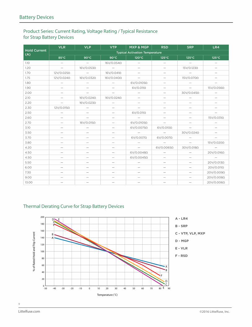
Product Series: Current Rating, Voltage Rating / Typical Resistance for Strap Battery Devices
Thermal Derating Curve for Strap Battery Devices
Hold Current (A)
VLR VLP VTP MXP & MGP RSD SRP LR4
Typical Activation Temperature
85°C 90°C 90°C 120°C 125°C 125°C 125°C
1.10 — — 16V/0.054Ω — — — —
1.20 — 16V/0.053Ω — — — 15V/0.123Ω —
1.70 12V/0.025Ω — 16V/0.041Ω — — — —
1.75 12V/0.024Ω 16V/0.032Ω 16V/0.040Ω — — 15V/0.070Ω —
1.80 — — — 6V/0.0105Ω — — —
1.90 — — — 6V/0.011Ω — — 15V/0.056Ω
2.00 — — — — — 30V/0.045Ω —
2.10 — 16V/0.024Ω 16V/0.024Ω — — — —
2.20 — 16V/0.023Ω — — — — —
2.30 12V/0.015Ω — — — — — —
2.50 — — — 6V/0.011Ω — — —
2.60 — — — — — — 15V/0.031Ω
2.70 — 16V/0.015Ω — 6V/0.0105Ω — — —
3.10 — — — 6V/0.0075Ω 6V/0.010Ω — —
3.50 — — — — — 30V/0.024Ω —
3.70 — — — 6V/0.007Ω 6V/0.007Ω — —
3.80 — — — — — — 15V/0.020Ω
4.20 — — — — 6V/0.0065Ω 30V/0.018Ω —
4.50 — — — 6V/0.0048Ω — — 20V/0.016Ω
4.50 — — — 6V/0.0045Ω — — —
5.50 — — — — — — 20V/0.013Ω
6.00 — — — — — — 20V/0.011Ω
7.30 — — — — — — 20V/0.009Ω
9.00 — — — — — — 20V/0.008Ω
13.00 — — — — — — 20V/0.006Ω
% o
f Rat
ed H
old
and
Trip
Cur
rent
Temperature (˚C)
200
180
160
140
120
100
80
60
40
20
0-50 -30-40 -10-20 20100 4030 6050 8070 90
A
AB
CD
E
B
DC
E
F
F
A - LR4
B - SRP
C - VTP, VLP, MXP
D - MGP
E - VLR
F - RSD
Littelfuse.com ©2016 Littelfuse, Inc.
10
Battery Devices
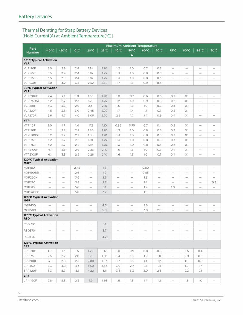
Part Number
Maximum Ambient Temperature
-40°C -20°C 0°C 20°C 25°C 40°C 50°C 60°C 70°C 75°C 80°C 85°C 90°C
A
85°C Typical ActivationVLR*
VLR170F 3.5 2.9 2.4 1.84 1.70 1.2 1.0 0.7 0.3 — — — —
VLR175F 3.5 2.9 2.4 1.87 1.75 1.3 1.0 0.8 0.3 — — — —
VLR175LF 3.5 2.9 2.4 1.87 1.75 1.3 1.0 0.8 0.3 — — — —
VLR230F 5.0 4.2 3.4 2.52 2.30 1.7 1.3 0.9 0.4 — — — —
90°C Typical ActivationVLP*
VLP120UF 2.4 2.1 1.8 1.30 1.20 1.0 0.7 0.6 0.3 0.2 0.1 — —
VLP175UAF 3.2 2.7 2.3 1.70 1.75 1.2 1.0 0.9 0.5 0.2 0.1 — —
VLP210F 4.3 3.6 2.9 2.31 2.10 1.6 1.3 1.0 0.6 0.3 0.1 — —
VLP220F 4.5 3.8 3.0 2.45 2.20 1.7 1.4 1.1 0.7 0.3 0.1 — —
VLP270F 5.6 4.7 4.0 3.05 2.70 2.2 1.7 1.4 0.9 0.4 0.1 — —
VTP*
VTP110F 2.0 1.7 1.4 1.12 1.10 0.85 0.75 0.7 0.4 0.2 0.1 — —
VTP170F 3.2 2.7 2.2 1.80 1.70 1.3 1.0 0.8 0.5 0.3 0.1 — —
VTP170XSF 3.2 2.7 2.2 1.80 1.70 1.3 1.0 0.8 0.5 0.3 0.1 — —
VTP175F 3.2 2.7 2.2 1.84 1.75 1.3 1.0 0.8 0.5 0.3 0.1 — —
VTP175LF 3.2 2.7 2.2 1.84 1.75 1.3 1.0 0.8 0.5 0.3 0.1 — —
VTP210GF 4.1 3.5 2.9 2.26 2.10 1.6 1.3 1.0 0.7 0.4 0.1 — —
VTP210SF 4.1 3.5 2.9 2.26 2.10 1.6 1.3 1.0 0.7 0.4 0.1 — —
120°C Typical ActivationMXP*
MXP180 — — 2.45 — 1.8 — — 0.80 — — — — —
MXP190BB — — 2.6 — 1.9 — — 0.85 — — — — —
MXP250K — — 3.6 — 2.5 — — 1.3 — — — — —
MXP270 — — 3.8 — 2.7 — — 1.4 — — — — 0.3
MXP310 — — 5.0 — 3.1 — — 1.9 — 1.0 — — —
MXP370BD — — 5.0 — 3.7 — — 1.9 — — — — —
120°C Typical ActivationMGP
MGP450 — — — — 4.5 — — 2.6 — — — — —
MGP500 — — — — 5.0 — — 3.0 2.0 — — — —
125°C Typical ActivationRSD
RSD 310 — — — — 3.1 — — — — — — — —
RSD370 — — — — 3.7 — — — — — — — —
RSD420 — — — — 4.2 — — — — — — — —
125°C Typical ActivationSRP
SRP120F 1.9 1.7 1.5 1.20 1.17 1.0 0.9 0.8 0.6 — 0.5 0.4 —
SRP175F 2.5 2.2 2.0 1.75 1.68 1.4 1.3 1.2 1.0 — 0.9 0.8 —
SRP200F 3.1 2.8 2.5 2.00 1.97 1.7 1.5 1.4 1.2 — 1.0 0.9 —
SRP350F 5.3 4.8 4.3 3.50 3.44 3.0 2.7 2.5 2.1 — 1.8 1.7 —
SRP420F 6.3 5.7 5.1 4.20 4.11 3.6 3.3 3.0 2.6 — 2.2 2.1 —
LR4
LR4-190F 2.8 2.5 2.3 1.9 1.86 1.6 1.5 1.4 1.2 — 1.1 1.0 —
Thermal Derating for Strap Battery Devices [Hold Current(A) at Ambient Temperature(°C)]
Littelfuse.com ©2016 Littelfuse, Inc.
11
Battery Devices
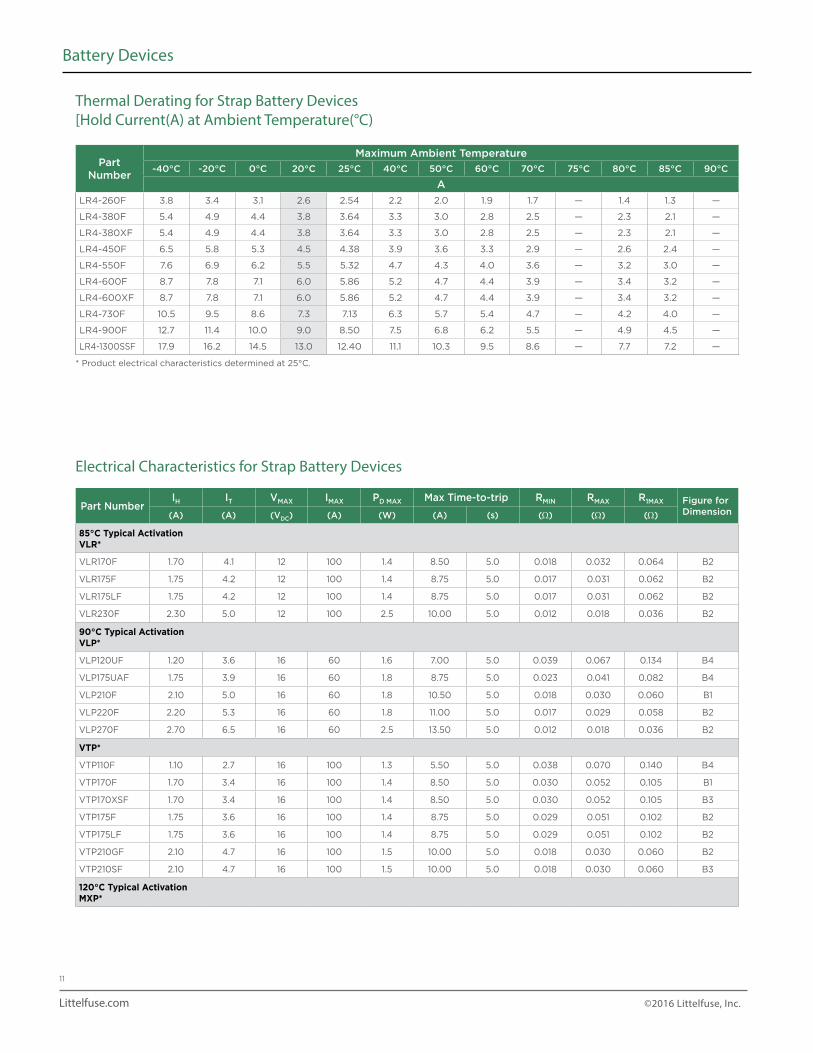
Thermal Derating for Strap Battery Devices [Hold Current(A) at Ambient Temperature(°C)
Part Number IH IT VMAX IMAX PD MAX Max Time-to-trip RMIN RMAX R1MAX Figure for
Dimension(A) (A) (VDC) (A) (W) (A) (s) (Ω) (Ω) (Ω)
85°C Typical ActivationVLR*
VLR170F 1.70 4.1 12 100 1.4 8.50 5.0 0.018 0.032 0.064 B2
VLR175F 1.75 4.2 12 100 1.4 8.75 5.0 0.017 0.031 0.062 B2
VLR175LF 1.75 4.2 12 100 1.4 8.75 5.0 0.017 0.031 0.062 B2
VLR230F 2.30 5.0 12 100 2.5 10.00 5.0 0.012 0.018 0.036 B2
90°C Typical ActivationVLP*
VLP120UF 1.20 3.6 16 60 1.6 7.00 5.0 0.039 0.067 0.134 B4
VLP175UAF 1.75 3.9 16 60 1.8 8.75 5.0 0.023 0.041 0.082 B4
VLP210F 2.10 5.0 16 60 1.8 10.50 5.0 0.018 0.030 0.060 B1
VLP220F 2.20 5.3 16 60 1.8 11.00 5.0 0.017 0.029 0.058 B2
VLP270F 2.70 6.5 16 60 2.5 13.50 5.0 0.012 0.018 0.036 B2
VTP*
VTP110F 1.10 2.7 16 100 1.3 5.50 5.0 0.038 0.070 0.140 B4
VTP170F 1.70 3.4 16 100 1.4 8.50 5.0 0.030 0.052 0.105 B1
VTP170XSF 1.70 3.4 16 100 1.4 8.50 5.0 0.030 0.052 0.105 B3
VTP175F 1.75 3.6 16 100 1.4 8.75 5.0 0.029 0.051 0.102 B2
VTP175LF 1.75 3.6 16 100 1.4 8.75 5.0 0.029 0.051 0.102 B2
VTP210GF 2.10 4.7 16 100 1.5 10.00 5.0 0.018 0.030 0.060 B2
VTP210SF 2.10 4.7 16 100 1.5 10.00 5.0 0.018 0.030 0.060 B3
120°C Typical ActivationMXP*
Electrical Characteristics for Strap Battery Devices
Part Number
Maximum Ambient Temperature
-40°C -20°C 0°C 20°C 25°C 40°C 50°C 60°C 70°C 75°C 80°C 85°C 90°C
A
LR4-260F 3.8 3.4 3.1 2.6 2.54 2.2 2.0 1.9 1.7 — 1.4 1.3 —
LR4-380F 5.4 4.9 4.4 3.8 3.64 3.3 3.0 2.8 2.5 — 2.3 2.1 —
LR4-380XF 5.4 4.9 4.4 3.8 3.64 3.3 3.0 2.8 2.5 — 2.3 2.1 —
LR4-450F 6.5 5.8 5.3 4.5 4.38 3.9 3.6 3.3 2.9 — 2.6 2.4 —
LR4-550F 7.6 6.9 6.2 5.5 5.32 4.7 4.3 4.0 3.6 — 3.2 3.0 —
LR4-600F 8.7 7.8 7.1 6.0 5.86 5.2 4.7 4.4 3.9 — 3.4 3.2 —
LR4-600XF 8.7 7.8 7.1 6.0 5.86 5.2 4.7 4.4 3.9 — 3.4 3.2 —
LR4-730F 10.5 9.5 8.6 7.3 7.13 6.3 5.7 5.4 4.7 — 4.2 4.0 —
LR4-900F 12.7 11.4 10.0 9.0 8.50 7.5 6.8 6.2 5.5 — 4.9 4.5 —
LR4-1300SSF 17.9 16.2 14.5 13.0 12.40 11.1 10.3 9.5 8.6 — 7.7 7.2 —
* Product electrical characteristics determined at 25°C.
Littelfuse.com ©2016 Littelfuse, Inc.
12
Battery Devices
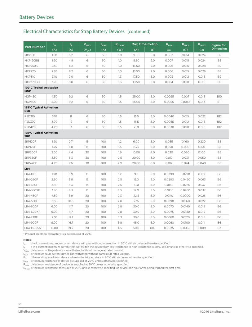
Part Number IH IT VMAX IMAX PD MAX Max Time-to-trip RMIN RMAX R1MAX Figure for
Dimension(A) (A) (VDC) (A) (W) (A) (s) (Ω) (Ω) (Ω)
MXP180 1.80 5.2 6 50 1.0 9.00 5.0 0.007 0.014 0.024 B9
MXP190BB 1.90 4.9 6 50 1.0 9.50 2.0 0.007 0.015 0.024 B8
MXP250K 2.50 6.2 6 50 1.0 13.50 2.0 0.006 0.016 0.028 B9
MXP270 2.70 6.2 6 50 1.0 13.50 2.0 0.006 0.015 0.026 B9
MXP310 3.10 9.0 6 50 1.3 17.50 5.0 0.003 0.012 0.018 B9
MXP370BD 3.70 9.0 6 50 1.3 18.50 5.0 0.004 0.010 0.016 B9
120°C Typical ActivationMGP
MGP450 4.50 9.2 6 50 1.5 25.00 5.0 0.0025 0.007 0.013 B10
MGP500 5.00 9.2 6 50 1.5 25.00 5.0 0.0025 0.0065 0.013 B11
125°C Typical ActivationRSD
RSD310 3.10 11 6 50 1.5 15.5 5.0 0.0040 0.015 0.022 B12
RSD370 3.70 12 6 50 1.5 18.5 5.0 0.0035 0.012 0.018 B12
RSD420 4.20 13 6 50 1.5 21.0 5.0 0.0030 0.010 0.016 B12
125°C Typical ActivationSRP
SRP120F 1.20 2.7 15 100 1.2 6.00 5.0 0.085 0.160 0.220 B5
SRP175F 1.75 3.8 15 100 1.5 8.75 5.0 0.050 0.090 0.120 B5
SRP200F 2.00 4.4 30 100 1.9 10.00 4.0 0.030 0.060 0.100 B5
SRP350F 3.50 6.3 30 100 2.5 20.00 3.0 0.017 0.031 0.050 B5
SRP420F 4.20 7.6 30 100 2.9 20.00 6.0 0.012 0.024 0.040 B5
LR4
LR4-190F 1.90 3.9 15 100 1.2 9.5 5.0 0.0390 0.0720 0.102 B6
LR4-260F 2.60 5.8 15 100 2.5 13.0 5.0 0.0200 0.0420 0.063 B6
LR4-380F 3.80 8.3 15 100 2.5 19.0 5.0 0.0130 0.0260 0.037 B6
LR4-380XF 3.80 8.3 15 100 2.5 19.0 5.0 0.0130 0.0260 0.037 B6
LR4-450F 4.50 8.9 20 100 2.3 22.5 5.0 0.0110 0.0200 0.028 B6
LR4-550F 5.50 10.5 20 100 2.8 27.5 5.0 0.0090 0.0160 0.022 B6
LR4-600F 6.00 11.7 20 100 2.8 30.0 5.0 0.0070 0.0140 0.019 B6
LR4-600XF 6.00 11.7 20 100 2.8 30.0 5.0 0.0075 0.0140 0.019 B6
LR4-730F 7.30 14.1 20 100 3.3 30.0 5.0 0.0060 0.0120 0.015 B6
LR4-900F 9.00 16.7 20 100 3.8 45.0 5.0 0.0060 0.0100 0.014 B6
LR4-1300SSF 13.00 21.2 20 100 4.5 50.0 10.0 0.0035 0.0065 0.009 B7
* Product electrical characteristics determined at 25°C.
Notes:IH : Hold current: maximum current device will pass without interruption in 20°C still air unless otherwise specified.IT : Trip current: minimum current that will switch the device from low-resistance to high-resistance in 20°C still air unless otherwise specified.VMAX : Maximum voltage device can withstand without damage at rated current.IMAX : Maximum fault current device can withstand without damage at rated voltage.PD : Power dissipated from device when in the tripped state in 20°C still air unless otherwise specified.RMIN : Minimum resistance of device as supplied at 20°C unless otherwise specified.RMAX : Maximum resistance of device as supplied at 20°C unless otherwise specified.R1MAX : Maximum resistance, measured at 20°C unless otherwise specified, of device one hour after being tripped the first time.
Electrical Characteristics for Strap Battery Devices (continued)
Littelfuse.com ©2016 Littelfuse, Inc.
13
Battery Devices
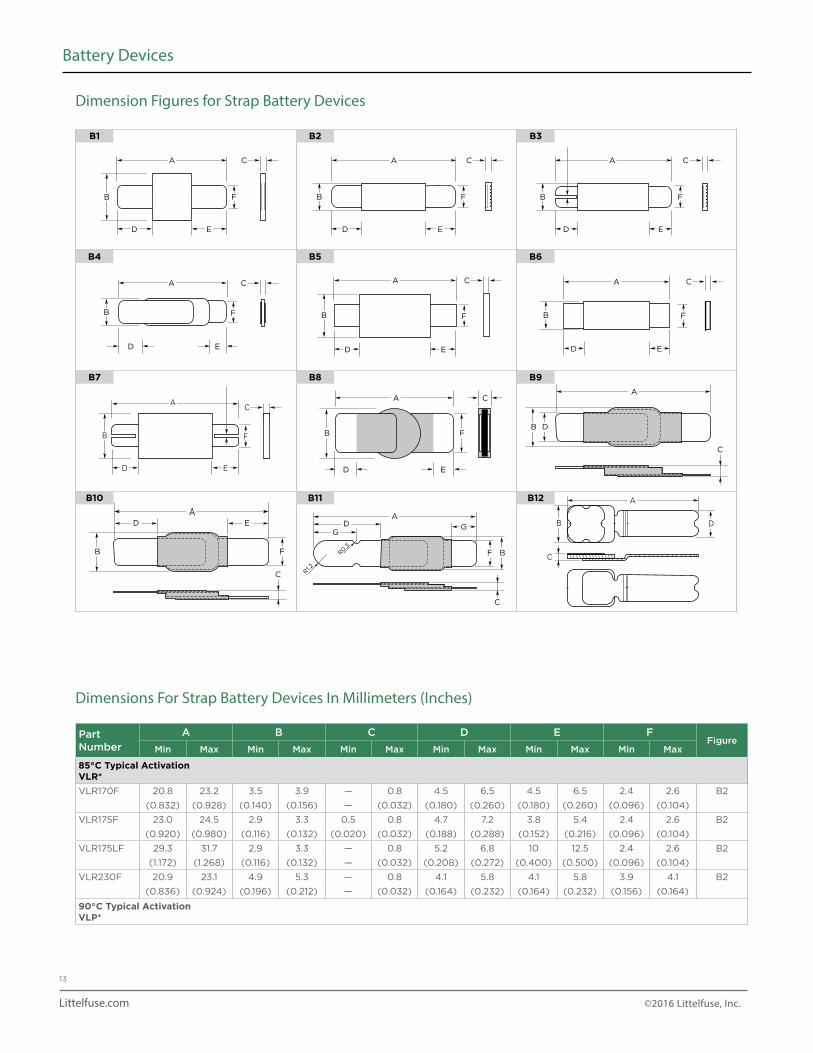
B1 B2 B3
B4 B5 B6
B7 B8 B9
B10 B11 B12
Dimension Figures for Strap Battery Devices
A A
B
B B
B BF
F F
F F
D E
D E
D ED E
D E D E
C A C C
A
B F
D E
CA CA C
B F
A C
B BF
C
C
A
F
ADD E
G
R0.3
R1.2
G
B F
D E
AC
B D
C
A
A A
B
B B
B BF
F F
F F
D E
D E
D ED E
D E D E
C A C C
A
B F
D E
CA CA C
B F
A C
B BF
C
C
A
F
ADD E
G
R0.3
R1.2
G
B F
D E
AC
B D
C
A
A A
B
B B
B BF
F F
F F
D E
D E
D ED E
D E D E
C A C C
A
B F
D E
CA CA C
B F
A C
B BF
C
C
A
F
ADD E
G
R0.3
R1.2
G
B F
D E
AC
B D
C
A
A A
B
B B
B BF
F F
F F
D E
D E
D ED E
D E D E
C A C C
A
B F
D E
CA CA C
B F
A C
B BF
C
C
A
F
ADD E
G
R0.3
R1.2
G
B F
D E
AC
B D
C
A
A A
B
B B
B BF
F F
F F
D E
D E
D ED E
D E D E
C A C C
A
B F
D E
CA CA C
B F
A C
B BF
C
C
A
F
ADD E
G
R0.3
R1.2
G
B F
D E
AC
B D
C
A
A A
B
B B
B BF
F F
F F
D E
D E
D ED E
D E D E
C A C C
A
B F
D E
CA CA C
B F
A C
B BF
C
C
A
F
ADD E
G
R0.3
R1.2
G
B F
D E
AC
B D
C
A
A A
B
B B
B BF
F F
F F
D E
D E
D ED E
D E D E
C A C C
A
B F
D E
CA CA C
B F
A C
B BF
C
C
A
F
ADD E
G
R0.3
R1.2
G
B F
D E
AC
B D
C
A
A A
B
B B
B BF
F F
F F
D E
D E
D ED E
D E D E
C A C C
A
B F
D E
CA CA C
B F
A C
B BF
C
C
A
F
ADD E
G
R0.3
R1.2
G
B F
D E
AC
B D
C
A
A A
B
B B
B BF
F F
F F
D E
D E
D ED E
D E D E
C A C C
A
B F
D E
CA CA C
B F
A C
B BF
C
C
A
F
ADD E
G
R0.3
R1.2
G
B F
D E
AC
B D
C
A
A A
B
B B
B BF
F F
F F
D E
D E
D ED E
D E D E
C A C C
A
B F
D E
CA CA C
B F
A C
B BF
C
C
A
F
ADD E
G
R0.3
R1.2
G
B F
D E
AC
B D
C
A
A A
B
B B
B BF
F F
F F
D E
D E
D ED E
D E D E
C A C C
A
B F
D E
CA CA C
B F
A C
B BF
C
C
A
F
ADD E
G
R0.3
R1.2
G
B F
D E
AC
B D
C
A
Part Number
A B C D E FFigure
Min Max Min Max Min Max Min Max Min Max Min Max
85°C Typical ActivationVLR*VLR170F 20.8 23.2 3.5 3.9 — 0.8 4.5 6.5 4.5 6.5 2.4 2.6 B2
(0.832) (0.928) (0.140) (0.156) — (0.032) (0.180) (0.260) (0.180) (0.260) (0.096) (0.104)
VLR175F 23.0 24.5 2.9 3.3 0.5 0.8 4.7 7.2 3.8 5.4 2.4 2.6 B2
(0.920) (0.980) (0.116) (0.132) (0.020) (0.032) (0.188) (0.288) (0.152) (0.216) (0.096) (0.104)
VLR175LF 29.3 31.7 2.9 3.3 — 0.8 5.2 6.8 10 12.5 2.4 2.6 B2
(1.172) (1.268) (0.116) (0.132) — (0.032) (0.208) (0.272) (0.400) (0.500) (0.096) (0.104)
VLR230F 20.9 23.1 4.9 5.3 — 0.8 4.1 5.8 4.1 5.8 3.9 4.1 B2
(0.836) (0.924) (0.196) (0.212) — (0.032) (0.164) (0.232) (0.164) (0.232) (0.156) (0.164)
90°C Typical ActivationVLP*
Dimensions For Strap Battery Devices In Millimeters (Inches)
B
C
D
A
Littelfuse.com ©2016 Littelfuse, Inc.
14
Battery Devices
Part Number
A B C D E F GFigure
Min Max Min Max Min Max Min Max Min Max Min Max Min Max
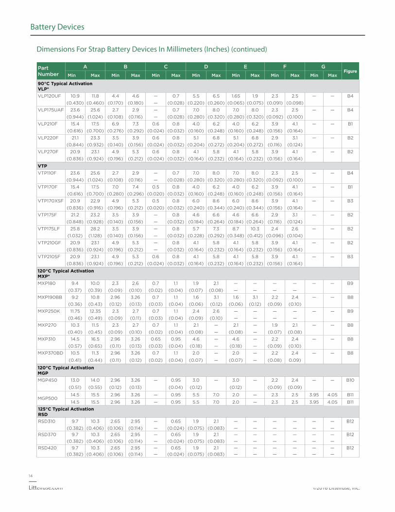
90°C Typical ActivationVLP*VLP120UF 10.9 11.8 4.4 4.6 — 0.7 5.5 6.5 1.65 1.9 2.3 2.5 — — B4
(0.430) (0.460) (0.170) (0.180) — (0.028) (0.220) (0.260) (0.065) (0.075) (0.091) (0.098)
VLP175UAF 23.6 25.6 2.7 2.9 — 0.7 7.0 8.0 7.0 8.0 2.3 2.5 — — B4
(0.944) (1.024) (0.108) (0.116) — (0.028) (0.280) (0.320) (0.280) (0.320) (0.092) (0.100)
VLP210F 15.4 17.5 6.9 7.3 0.6 0.8 4.0 6.2 4.0 6.2 3.9 4.1 — — B1
(0.616) (0.700) (0.276) (0.292) (0.024) (0.032) (0.160) (0.248) (0.160) (0.248) (0.156) (0.164)
VLP220F 21.1 23.3 3.5 3.9 0.6 0.8 5.1 6.8 5.1 6.8 2.9 3.1 — — B2
(0.844) (0.932) (0.140) (0.156) (0.024) (0.032) (0.204) (0.272) (0.204) (0.272) (0.116) (0.124)
VLP270F 20.9 23.1 4.9 5.3 0.6 0.8 4.1 5.8 4.1 5.8 3.9 4.1 — — B2
(0.836) (0.924) (0.196) (0.212) (0.024) (0.032) (0.164) (0.232) (0.164) (0.232) (0.156) (0.164)
VTPVTP110F 23.6 25.6 2.7 2.9 — 0.7 7.0 8.0 7.0 8.0 2.3 2.5 — — B4
(0.944) (1.024) (0.108) (0.116) — (0.028) (0.280) (0.320) (0.280) (0.320) (0.092) (0.100)
VTP170F 15.4 17.5 7.0 7.4 0.5 0.8 4.0 6.2 4.0 6.2 3.9 4.1 — — B1
(0.616) (0.700) (0.280) (0.296) (0.020) (0.032) (0.160) (0.248) (0.160) (0.248) (0.156) (0.164)
VTP170XSF 20.9 22.9 4.9 5.3 0.5 0.8 6.0 8.6 6.0 8.6 3.9 4.1 — — B3
(0.836) (0.916) (0.196) (0.212) (0.020) (0.032) (0.240) (0.344) (0.240) (0.344) (0.156) (0.164)
VTP175F 21.2 23.2 3.5 3.9 — 0.8 4.6 6.6 4.6 6.6 2.9 3.1 — — B2
(0.848) (0.928) (0.140) (0.156) — (0.032) (0.184) (0.264) (0.184) (0.264) (0.116) (0.124)
VTP175LF 25.8 28.2 3.5 3.9 — 0.8 5.7 7.3 8.7 10.3 2.4 2.6 — — B2
(1.032) (1.128) (0.140) (0.156) — (0.032) (0.228) (0.292) (0.348) (0.412) (0.096) (0.104)
VTP210GF 20.9 23.1 4.9 5.3 — 0.8 4.1 5.8 4.1 5.8 3.9 4.1 — — B2
(0.836) (0.924) (0.196) (0.212) — (0.032) (0.164) (0.232) (0.164) (0.232) (0.156) (0.164)
VTP210SF 20.9 23.1 4.9 5.3 0.6 0.8 4.1 5.8 4.1 5.8 3.9 4.1 — — B3
(0.836) (0.924) (0.196) (0.212) (0.024) (0.032) (0.164) (0.232) (0.164) (0.232) (0.156) (0.164)
120°C Typical ActivationMXP*MXP180 9.4 10.0 2.3 2.6 0.7 1.1 1.9 2.1 — — — — — — B9
(0.37) (0.39) (0.09) (0.10) (0.02) (0.04) (0.07) (0.08) — — — —
MXP190BB 9.2 10.8 2.96 3.26 0.7 1.1 1.6 3.1 1.6 3.1 2.2 2.4 — — B8
(0.36) (0.43) (0.12) (0.13) (0.03) (0.04) (0.06) (0.12) (0.06) (0.12) (0.09) (0.10)
MXP250K 11.75 12.35 2.3 2.7 0.7 1.1 2.4 2.6 — — — — — — B9
(0.46) (0.49) (0.09) (0.11) (0.03) (0.04) (0.09) (0.10) — — — —
MXP270 10.3 11.5 2.3 2.7 0.7 1.1 2.1 — 2.1 — 1.9 2.1 — — B8
(0.40) (0.45) (0.09) (0.10) (0.02) (0.04) (0.08) — (0.08) — (0.07) (0.08)
MXP310 14.5 16.5 2.96 3.26 0.65 0.95 4.6 — 4.6 — 2.2 2.4 — — B8
(0.57) (0.65) (0.11) (0.13) (0.03) (0.04) (0.18) — (0.18) — (0.09) (0.10)
MXP370BD 10.5 11.3 2.96 3.26 0.7 1.1 2.0 — 2.0 — 2.2 2.4 — — B8
(0.41) (0.44) (0.11) (0.12) (0.02) (0.04) (0.07) — (0.07) — (0.08) 0.09)
120°C Typical ActivationMGPMGP450 13.0 14.0 2.96 3.26 — 0.95 3.0 — 3.0 — 2.2 2.4 — — B10
(0.51) (0.55) (0.12) (0.13) (0.04) (0.12) (0.12) (0.09) (0.09)
MGP50014.5 15.5 2.96 3.26 — 0.95 5.5 7.0 2.0 — 2.3 2.5 3.95 4.05 B11
14.5 15.5 2.96 3.26 — 0.95 5.5 7.0 2.0 — 2.3 2.5 3.95 4.05 B11
125°C Typical ActivationRSDRSD310 9.7 10.3 2.65 2.95 — 0.65 1.9 2.1 — — — — — — B12
(0.382) (0.406) (0.106) (0.114) — (0.024) (0.075) (0.083) — — — — — —
RSD370 9.7 10.3 2.65 2.95 — 0.65 1.9 2.1 — — — — — — B12
(0.382) (0.406) (0.106) (0.114) — (0.024) (0.075) (0.083) — — — — — —
RSD420 9.7 10.3 2.65 2.95 — 0.65 1.9 2.1 — — — — — — B12
(0.382) (0.406) (0.106) (0.114) — (0.024) (0.075) (0.083) — — — — — —
Dimensions For Strap Battery Devices In Millimeters (Inches) (continued)
Littelfuse.com ©2016 Littelfuse, Inc.
15
Battery Devices
100
10
1
0.10
0.01
0.001
Tim
e-t
o-T
rip
(s)
1 10 100
Fault Current (A)
AB
C
ABC
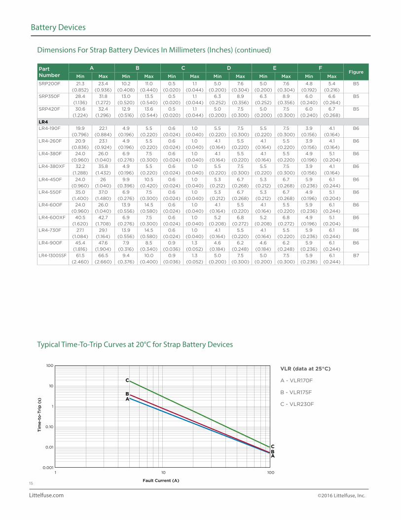
VLR (data at 25°C)
A - VLR170F
B - VLR175F
C - VLR230F
Part Number
A B C D E FFigure
Min Max Min Max Min Max Min Max Min Max Min Max
SRP200F 21.3 23.4 10.2 11.0 0.5 1.1 5.0 7.6 5.0 7.6 4.8 5.4 B5
(0.852) (0.936) (0.408) (0.440) (0.020) (0.044) (0.200) (0.304) (0.200) (0.304) (0.192) (0.216)
SRP350F 28.4 31.8 13.0 13.5 0.5 1.1 6.3 8.9 6.3 8.9 6.0 6.6 B5
(1.136) (1.272) (0.520) (0.540) (0.020) (0.044) (0.252) (0.356) (0.252) (0.356) (0.240) (0.264)
SRP420F 30.6 32.4 12.9 13.6 0.5 1.1 5.0 7.5 5.0 7.5 6.0 6.7 B5
(1.224) (1.296) (0.516) (0.544) (0.020) (0.044) (0.200) (0.300) (0.200) (0.300) (0.240) (0.268)
LR4LR4-190F 19.9 22.1 4.9 5.5 0.6 1.0 5.5 7.5 5.5 7.5 3.9 4.1 B6
(0.796) (0.884) (0.196) (0.220) (0.024) (0.040) (0.220) (0.300) (0.220) (0.300) (0.156) (0.164)
LR4-260F 20.9 23.1 4.9 5.5 0.6 1.0 4.1 5.5 4.1 5.5 3.9 4.1 B6
(0.836) (0.924) (0.196) (0.220) (0.024) (0.040) (0.164) (0.220) (0.164) (0.220) (0.156) (0.164)
LR4-380F 24.0 26.0 6.9 7.5 0.6 1.0 4.1 5.5 4.1 5.5 4.9 5.1 B6
(0.960) (1.040) (0.276) (0.300) (0.024) (0.040) (0.164) (0.220) (0.164) (0.220) (0.196) (0.204)
LR4-380XF 32.2 35.8 4.9 5.5 0.6 1.0 5.5 7.5 5.5 7.5 3.9 4.1 B6
(1.288) (1.432) (0.196) (0.220) (0.024) (0.040) (0.220) (0.300) (0.220) (0.300) (0.156) (0.164)
LR4-450F 24.0 26 9.9 10.5 0.6 1.0 5.3 6.7 5.3 6.7 5.9 6.1 B6
(0.960) (1.040) (0.396) (0.420) (0.024) (0.040) (0.212) (0.268) (0.212) (0.268) (0.236) (0.244)
LR4-550F 35.0 37.0 6.9 7.5 0.6 1.0 5.3 6.7 5.3 6.7 4.9 5.1 B6
(1.400) (1.480) (0.276) (0.300) (0.024) (0.040) (0.212) (0.268) (0.212) (0.268) (0.196) (0.204)
LR4-600F 24.0 26.0 13.9 14.5 0.6 1.0 4.1 5.5 4.1 5.5 5.9 6.1 B6
(0.960) (1.040) (0.556) (0.580) (0.024) (0.040) (0.164) (0.220) (0.164) (0.220) (0.236) (0.244)
LR4-600XF 40.5 42.7 6.9 7.5 0.6 1.0 5.2 6.8 5.2 6.8 4.9 5.1 B6
(1.620) (1.708) (0.276) (0.300) (0.024) (0.040) (0.208) (0.272) (0.208) (0.272) (0.196) (0.204)
LR4-730F 27.1 29.1 13.9 14.5 0.6 1.0 4.1 5.5 4.1 5.5 5.9 6.1 B6
(1.084) (1.164) (0.556) (0.580) (0.024) (0.040) (0.164) (0.220) (0.164) (0.220) (0.236) (0.244)
LR4-900F 45.4 47.6 7.9 8.5 0.9 1.3 4.6 6.2 4.6 6.2 5.9 6.1 B6
(1.816) (1.904) (0.316) (0.340) (0.036) (0.052) (0.184) (0.248) (0.184) (0.248) (0.236) (0.244)
LR4-1300SSF 61.5 66.5 9.4 10.0 0.9 1.3 5.0 7.5 5.0 7.5 5.9 6.1 B7
(2.460) (2.660) (0.376) (0.400) (0.036) (0.052) (0.200) (0.300) (0.200) (0.300) (0.236) (0.244)
Dimensions For Strap Battery Devices In Millimeters (Inches) (continued)
Typical Time-To-Trip Curves at 20°C for Strap Battery Devices
Littelfuse.com ©2016 Littelfuse, Inc.
16
Battery Devices
100
10
1
0.10
0.01
0.001
0.0001
Tim
e-t
o-T
rip
(s)
1 10 100
Fault Current (A)
A
A
B
B
C
C
D
D
E
E
100
10
1
0.10
0.01
0.001
Tim
e-t
o-T
rip
(s)
1 10 100
Fault Current (A)
A
A
B
B
C
C
D
D
10
1
0.1
0.01
0.001
Tim
e-t
o-T
rip
(s)
1 10 100
Fault Current (A)
A
A
B
B
C
C
D E
E
F
F
D
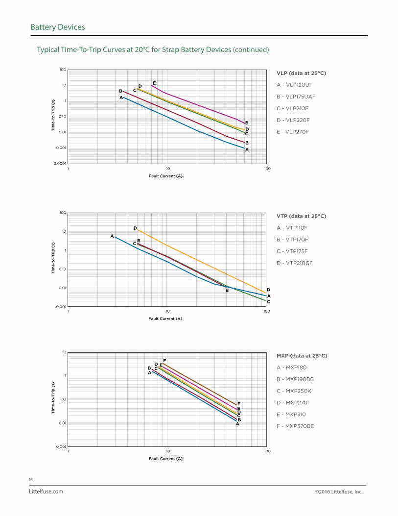
VLP (data at 25°C)
A - VLP120UF
B - VLP175UAF
C - VLP210F
D - VLP220F
E - VLP270F
VTP (data at 25°C)
A - VTP110F
B - VTP170F
C - VTP175F
D - VTP210GF
MXP (data at 25°C)
A - MXP180
B - MXP190BB
C - MXP250K
D - MXP270
E - MXP310
F - MXP370BD
Typical Time-To-Trip Curves at 20°C for Strap Battery Devices (continued)
Littelfuse.com ©2016 Littelfuse, Inc.
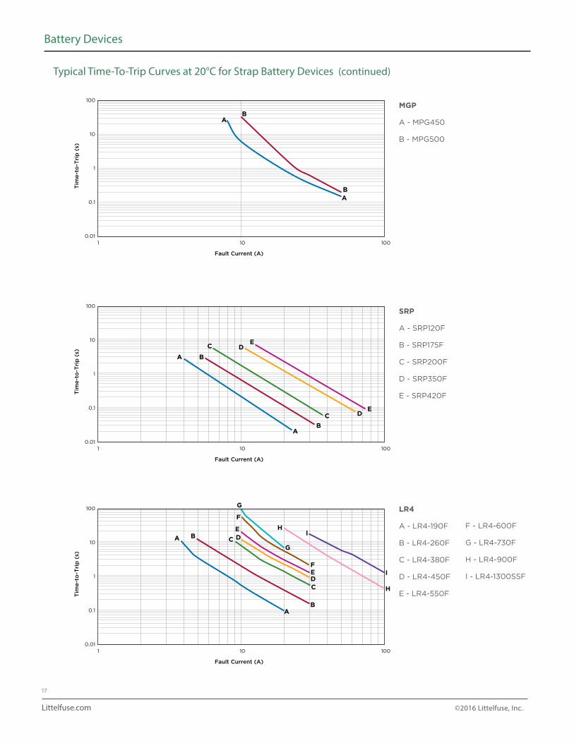
17
Battery Devices
100
10
1
0.1
0.01
Tim
e-t
o-T
rip
(s)
1 10 100
Fault Current (A)
A
A
B
B
MGP
A - MPG450
B - MPG500
100
10
1
0.1
0.01
Tim
e-t
o-T
rip
(s)
1 10 100
Fault Current (A)
A
A
B
B
C
C
DE
ED
100
10
1
0.1
0.01
Tim
e-t
o-T
rip
(s)
1 10 100
Fault Current (A)
A
A
B
B
C
C
DE
F
F
G
G
H
H
I
IED
SRP
A - SRP120F
B - SRP175F
C - SRP200F
D - SRP350F
E - SRP420F
LR4
A - LR4-190F
B - LR4-260F
C - LR4-380F
D - LR4-450F
E - LR4-550F
F - LR4-600F
G - LR4-730F
H - LR4-900F
I - LR4-1300SSF
Typical Time-To-Trip Curves at 20°C for Strap Battery Devices (continued)
Littelfuse.com ©2016 Littelfuse, Inc.
18
Battery Devices
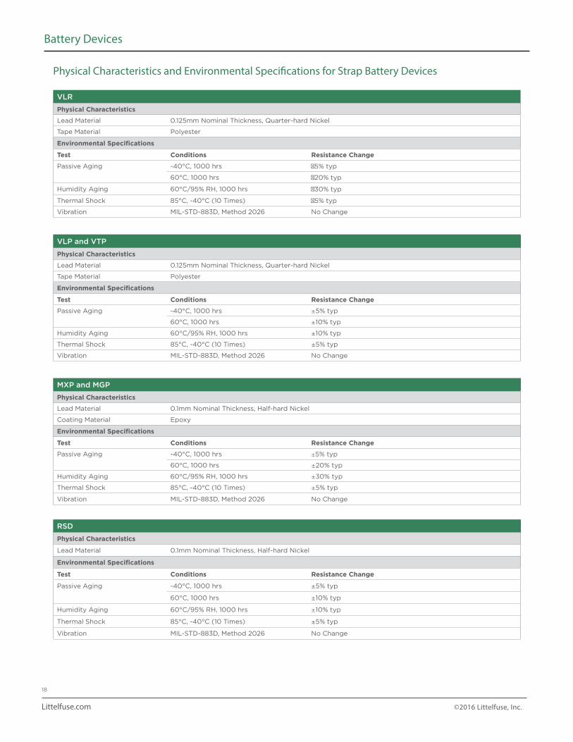
Physical Characteristics and Environmental Specifications for Strap Battery Devices
VLR
Physical Characteristics
Lead Material 0.125mm Nominal Thickness, Quarter-hard Nickel
Tape Material Polyester
Environmental Specifications
Test Conditions Resistance Change
Passive Aging -40°C, 1000 hrs 5% typ
60°C, 1000 hrs 20% typ
Humidity Aging 60°C/95% RH, 1000 hrs 30% typ
Thermal Shock 85°C, -40°C (10 Times) 5% typ
Vibration MIL-STD-883D, Method 2026 No Change
VLP and VTP
Physical Characteristics
Lead Material 0.125mm Nominal Thickness, Quarter-hard Nickel
Tape Material Polyester
Environmental Specifications
Test Conditions Resistance Change
Passive Aging -40°C, 1000 hrs ±5% typ
60°C, 1000 hrs ±10% typ
Humidity Aging 60°C/95% RH, 1000 hrs ±10% typ
Thermal Shock 85°C, -40°C (10 Times) ±5% typ
Vibration MIL-STD-883D, Method 2026 No Change
MXP and MGP
Physical Characteristics
Lead Material 0.1mm Nominal Thickness, Half-hard Nickel
Coating Material Epoxy
Environmental Specifications
Test Conditions Resistance Change
Passive Aging -40°C, 1000 hrs ±5% typ
60°C, 1000 hrs ±20% typ
Humidity Aging 60°C/95% RH, 1000 hrs ±30% typ
Thermal Shock 85°C, -40°C (10 Times) ±5% typ
Vibration MIL-STD-883D, Method 2026 No Change
RSD
Physical Characteristics
Lead Material 0.1mm Nominal Thickness, Half-hard Nickel
Environmental Specifications
Test Conditions Resistance Change
Passive Aging -40°C, 1000 hrs ±5% typ
60°C, 1000 hrs ±10% typ
Humidity Aging 60°C/95% RH, 1000 hrs ±10% typ
Thermal Shock 85°C, -40°C (10 Times) ±5% typ
Vibration MIL-STD-883D, Method 2026 No Change
Littelfuse.com ©2016 Littelfuse, Inc.
19
Battery Devices
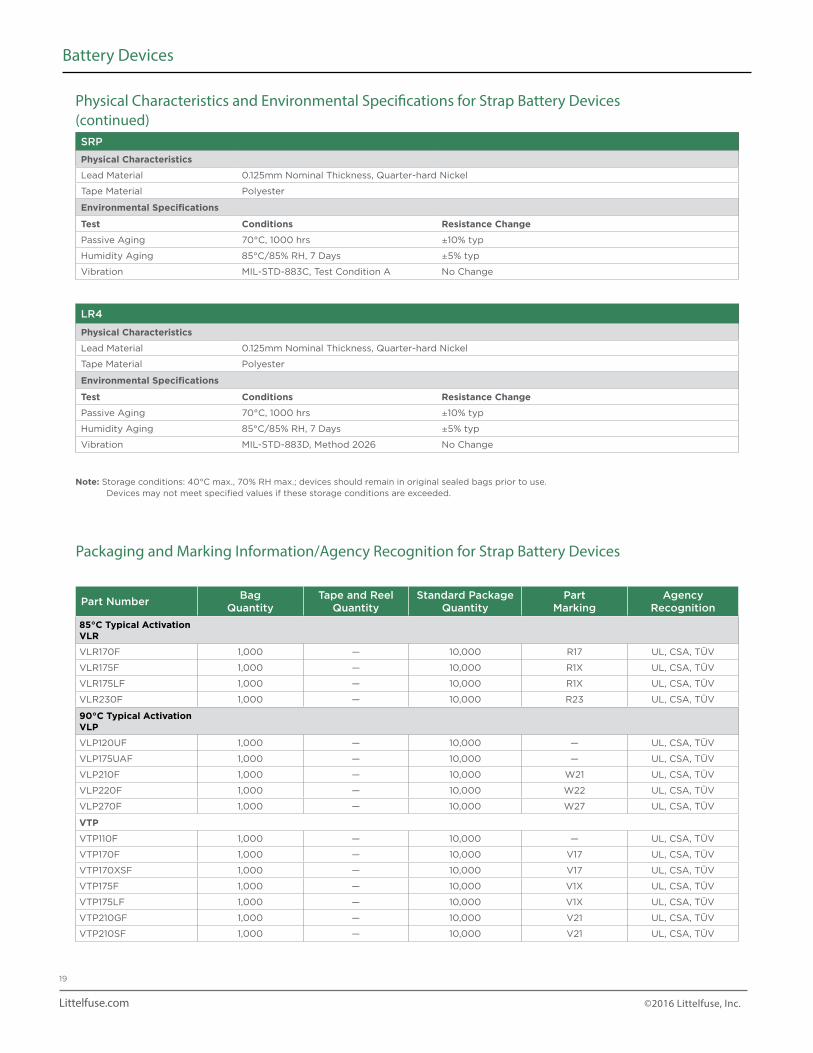
Physical Characteristics and Environmental Specifications for Strap Battery Devices(continued)SRP
Physical Characteristics
Lead Material 0.125mm Nominal Thickness, Quarter-hard Nickel
Tape Material Polyester
Environmental Specifications
Test Conditions Resistance Change
Passive Aging 70°C, 1000 hrs ±10% typ
Humidity Aging 85°C/85% RH, 7 Days ±5% typ
Vibration MIL-STD-883C, Test Condition A No Change
LR4
Physical Characteristics
Lead Material 0.125mm Nominal Thickness, Quarter-hard Nickel
Tape Material Polyester
Environmental Specifications
Test Conditions Resistance Change
Passive Aging 70°C, 1000 hrs ±10% typ
Humidity Aging 85°C/85% RH, 7 Days ±5% typ
Vibration MIL-STD-883D, Method 2026 No Change
Note: Storage conditions: 40°C max., 70% RH max.; devices should remain in original sealed bags prior to use. Devices may not meet specified values if these storage conditions are exceeded.
Part NumberBag
QuantityTape and Reel
QuantityStandard Package
QuantityPart
MarkingAgency
Recognition
85°C Typical ActivationVLR
VLR170F 1,000 — 10,000 R17 UL, CSA, TÜV
VLR175F 1,000 — 10,000 R1X UL, CSA, TÜV
VLR175LF 1,000 — 10,000 R1X UL, CSA, TÜV
VLR230F 1,000 — 10,000 R23 UL, CSA, TÜV
90°C Typical ActivationVLP
VLP120UF 1,000 — 10,000 — UL, CSA, TÜV
VLP175UAF 1,000 — 10,000 — UL, CSA, TÜV
VLP210F 1,000 — 10,000 W21 UL, CSA, TÜV
VLP220F 1,000 — 10,000 W22 UL, CSA, TÜV
VLP270F 1,000 — 10,000 W27 UL, CSA, TÜV
VTP
VTP110F 1,000 — 10,000 — UL, CSA, TÜV
VTP170F 1,000 — 10,000 V17 UL, CSA, TÜV
VTP170XSF 1,000 — 10,000 V17 UL, CSA, TÜV
VTP175F 1,000 — 10,000 V1X UL, CSA, TÜV
VTP175LF 1,000 — 10,000 V1X UL, CSA, TÜV
VTP210GF 1,000 — 10,000 V21 UL, CSA, TÜV
VTP210SF 1,000 — 10,000 V21 UL, CSA, TÜV
Packaging and Marking Information/Agency Recognition for Strap Battery Devices
Littelfuse.com ©2016 Littelfuse, Inc.
20
Battery Devices
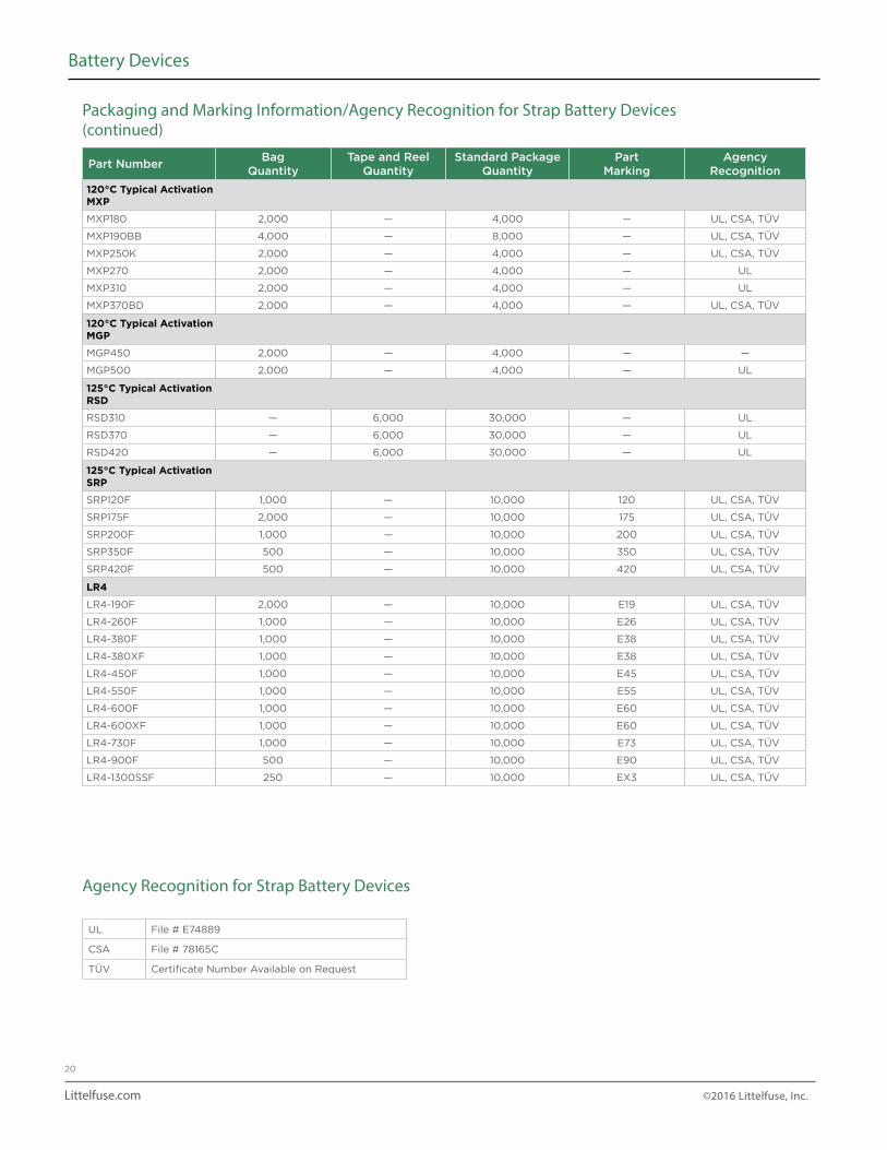
Agency Recognition for Strap Battery Devices
UL File # E74889
CSA File # 78165C
TÜV Certificate Number Available on Request
Part NumberBag
QuantityTape and Reel
QuantityStandard Package
QuantityPart
MarkingAgency
Recognition
120°C Typical ActivationMXP
MXP180 2,000 — 4,000 — UL, CSA, TÜV
MXP190BB 4,000 — 8,000 — UL, CSA, TÜV
MXP250K 2,000 — 4,000 — UL, CSA, TÜV
MXP270 2,000 — 4,000 — UL
MXP310 2,000 — 4,000 — UL
MXP370BD 2,000 — 4,000 — UL, CSA, TÜV
120°C Typical ActivationMGP
MGP450 2,000 — 4,000 — —
MGP500 2,000 — 4,000 — UL
125°C Typical ActivationRSD
RSD310 — 6,000 30,000 — UL
RSD370 — 6,000 30,000 — UL
RSD420 — 6,000 30,000 — UL
125°C Typical ActivationSRP
SRP120F 1,000 — 10,000 120 UL, CSA, TÜV
SRP175F 2,000 — 10,000 175 UL, CSA, TÜV
SRP200F 1,000 — 10,000 200 UL, CSA, TÜV
SRP350F 500 — 10,000 350 UL, CSA, TÜV
SRP420F 500 — 10,000 420 UL, CSA, TÜV
LR4
LR4-190F 2,000 — 10,000 E19 UL, CSA, TÜV
LR4-260F 1,000 — 10,000 E26 UL, CSA, TÜV
LR4-380F 1,000 — 10,000 E38 UL, CSA, TÜV
LR4-380XF 1,000 — 10,000 E38 UL, CSA, TÜV
LR4-450F 1,000 — 10,000 E45 UL, CSA, TÜV
LR4-550F 1,000 — 10,000 E55 UL, CSA, TÜV
LR4-600F 1,000 — 10,000 E60 UL, CSA, TÜV
LR4-600XF 1,000 — 10,000 E60 UL, CSA, TÜV
LR4-730F 1,000 — 10,000 E73 UL, CSA, TÜV
LR4-900F 500 — 10,000 E90 UL, CSA, TÜV
LR4-1300SSF 250 — 10,000 EX3 UL, CSA, TÜV
Packaging and Marking Information/Agency Recognition for Strap Battery Devices (continued)
Littelfuse.com ©2016 Littelfuse, Inc.
21
Battery Devices
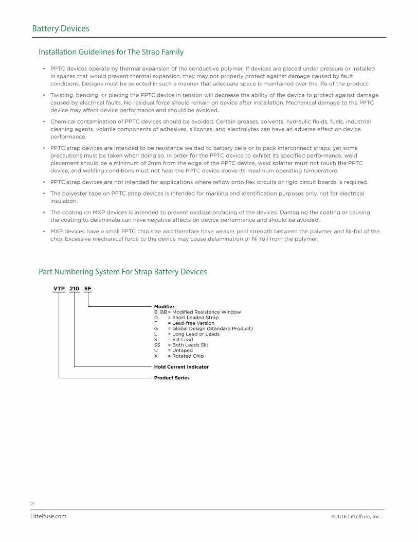
Installation Guidelines for The Strap Family
Part Numbering System For Strap Battery Devices
• PPTC devices operate by thermal expansion of the conductive polymer. If devices are placed under pressure or installed
in spaces that would prevent thermal expansion, they may not properly protect against damage caused by fault
conditions. Designs must be selected in such a manner that adequate space is maintained over the life of the product.
• Twisting, bending, or placing the PPTC device in tension will decrease the ability of the device to protect against damage
caused by electrical faults. No residual force should remain on device after installation. Mechanical damage to the PPTC
device may affect device performance and should be avoided.
• Chemical contamination of PPTC devices should be avoided. Certain greases, solvents, hydraulic fluids, fuels, industrial
cleaning agents, volatile components of adhesives, silicones, and electrolytes can have an adverse effect on device
performance.
• PPTC strap devices are intended to be resistance welded to battery cells or to pack interconnect straps, yet some
precautions must be taken when doing so. In order for the PPTC device to exhibit its specified performance, weld
placement should be a minimum of 2mm from the edge of the PPTC device, weld splatter must not touch the PPTC
device, and welding conditions must not heat the PPTC device above its maximum operating temperature.
• PPTC strap devices are not intended for applications where reflow onto flex circuits or rigid circuit boards is required.
• The polyester tape on PPTC strap devices is intended for marking and identification purposes only, not for electrical
insulation.
• The coating on MXP devices is intended to prevent oxidization/aging of the devices. Damaging the coating or causing
the coating to delaminate can have negative effects on device performance and should be avoided.
• MXP devices have a small PPTC chip size and therefore have weaker peel strength between the polymer and Ni-foil of the
chip. Excessive mechanical force to the device may cause delamination of Ni-foil from the polymer.
VTP 210 SF
ModifierB, BB = Modified Resistance WindowD = Short Leaded StrapF = Lead-free VersionG = Global Design (Standard Product)L = Long Lead or LeadsS = Slit LeadSS = Both Leads SlitU = UntapedX = Rotated Chip
Hold Current Indicator
Product Series
Littelfuse.com ©2016 Littelfuse, Inc.
22
Battery Devices
Part Number
Maximum Ambient Temperature
-40°C -20°C 0°C 20°C 25°C 40°C 50°C 60°C 70°C 80°C 85°C
A
nanoSMDLR Series Size 3216mm/1206mils
nanoSMD175LR 3.00 2.60 2.20 1.75 1.70 1.40 1.20 1.00 0.80 0.60 0.50
nanoSMD200LR 3.60 3.20 2.80 2.00 1.90 1.80 1.60 1.40 1.20 1.00 0.80
nanoSMD270LR 4.00 3.50 3.00 2.70 2.60 2.20 2.00 1.60 1.40 1.20 1.10
nanoSMD350LR 5.50 4.80 4.00 3.50 3.30 2.70 2.30 1.90 1.60 1.40 1.30
nanoSMD500LR 7.40 6.60 6.00 5.00 4.90 4.60 4.20 3.70 3.30 3.00 2.80
microSMDLR Series Size 3225mm/1210mils
microSMD190LR 3.40 2.90 2.40 1.90 1.80 1.40 1.15 0.90 0.65 0.40 0.28
microSMD200LR 3.50 3.00 2.50 2.00 1.90 1.50 1.25 1.00 0.75 0.50 0.38
microSMD250LR 4.40 3.80 3.20 2.50 2.40 1.90 1.60 1.30 1.00 0.65 0.50
microSMD350LR 5.40 4.75 4.00 3.50 3.20 2.70 2.40 2.00 1.70 1.35 1.20
microSMD450LR 7.00 6.20 5.50 4.50 4.40 3.80 3.50 3.20 2.75 2.35 2.16
* Data is preliminary.
Thermal Derating for low rho SMD Devices [Hold Current (A) at Ambient Temperature (°C)]
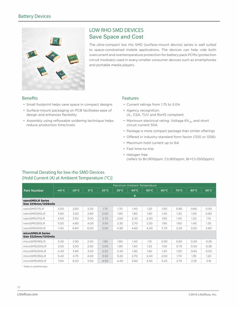
LOW RHO SMD DEVICESSave Space and CostThe ultra-compact low rho SMD (surface-mount device) series is well suited
to space-constrained mobile applications. The devices can help vide both
overcurrent and overtemperature protection for battery pack PCMs (protection
circuit modules) used in every-smaller consumer devices such as smartphones
and portable media players.
Benefits• Small footprint helps save space in compact designs
• Surface-mount packaging on PCB facilitates ease of design and enhances flexibility
• Assembly using reflowable soldering technique helps reduce production time/costs
Features• Current ratings from 1.75 to 5.0A
• Agency recognition: UL, CSA, TUV and RoHS compliant
• Maximum electrical rating: Voltage 6VDC and short circuit current 50A
• Package is more compact package than similar offerings
• Offered in industry-standard form factor (1210 or 1206)
• Maximum hold current up to 6A
• Fast time-to-trip
• Halogen free (refers to Br≤900ppm, CI≤900ppm, Br+CI≤1500ppm)
Littelfuse.com ©2016 Littelfuse, Inc.
23
Battery Devices
Electrical Characteristics for low rho SMD Devices at Room Temperature
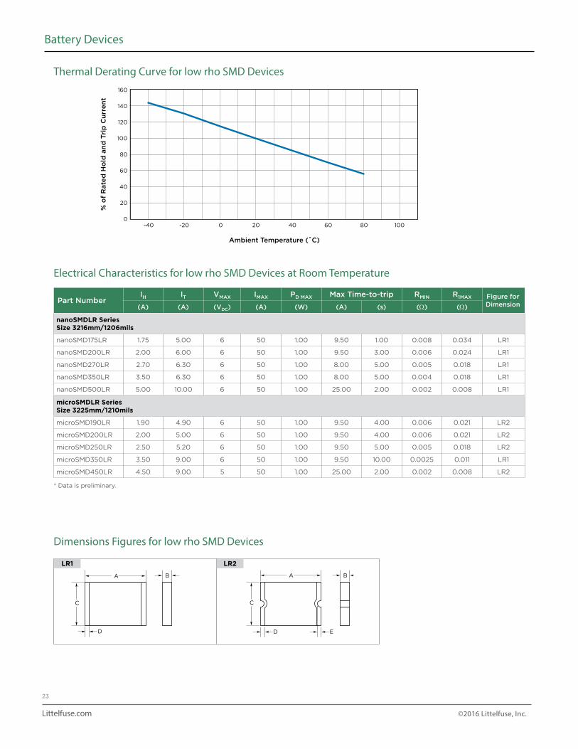
Thermal Derating Curve for low rho SMD Devices
Dimensions Figures for low rho SMD Devices
Part NumberIH IT VMAX IMAX PD MAX Max Time-to-trip RMIN R1MAX Figure for
Dimension(A) (A) (VDC) (A) (W) (A) (s) (Ω) (Ω)
nanoSMDLR Series Size 3216mm/1206mils
nanoSMD175LR 1.75 5.00 6 50 1.00 9.50 1.00 0.008 0.034 LR1
nanoSMD200LR 2.00 6.00 6 50 1.00 9.50 3.00 0.006 0.024 LR1
nanoSMD270LR 2.70 6.30 6 50 1.00 8.00 5.00 0.005 0.018 LR1
nanoSMD350LR 3.50 6.30 6 50 1.00 8.00 5.00 0.004 0.018 LR1
nanoSMD500LR 5.00 10.00 6 50 1.00 25.00 2.00 0.002 0.008 LR1
microSMDLR Series Size 3225mm/1210mils
microSMD190LR 1.90 4.90 6 50 1.00 9.50 4.00 0.006 0.021 LR2
microSMD200LR 2.00 5.00 6 50 1.00 9.50 4.00 0.006 0.021 LR2
microSMD250LR 2.50 5.20 6 50 1.00 9.50 5.00 0.005 0.018 LR2
microSMD350LR 3.50 9.00 6 50 1.00 9.50 10.00 0.0025 0.011 LR1
microSMD450LR 4.50 9.00 5 50 1.00 25.00 2.00 0.002 0.008 LR2
* Data is preliminary.
LR1 LR2
% o
f R
ate
d H
old
an
d T
rip
Cu
rre
nt
Ambient Temperature (˚C)
160
140
120
100
80
60
40
20
0-40 -20 200 40 60 80 100
C
A B
ED
C
A B
D
C
A B
ED
C
A B
D
Littelfuse.com ©2016 Littelfuse, Inc.
24
Battery Devices
Part NumberA B C D E
FigureMin Max Min Max Min Max Min Max Min
nanoSMDLR SeriesSize 3216mm/1206mils
nanoSMD175LR 3.00 3.43 0.50 1.00 1.37 1.85 0.25 0.75 — LR1
(0.118) (0.135) (0.019) (0.039) (0.054) (0.073) (0.010) (0.030)
nanoSMD200LR 3.00 3.43 0.50 1.00 1.37 1.85 0.25 0.75 — LR1
(0.118) (0.135) (0.019) (0.039) (0.054) (0.073) (0.010) (0.030)
nanoSMD270LR 3.00 3.43 0.50 1.00 1.37 1.85 0.25 0.75 — LR1
(0.118) (0.135) (0.019) (0.039) (0.054) (0.073) (0.010) (0.030)
nanoSMD350LR 3.00 3.43 0.50 1.00 1.37 1.85 0.25 0.75 — LR1
(0.118) (0.135) (0.019) (0.039) (0.054) (0.073) (0.010) (0.030)
nanoSMD500LR 3.00 3.43 0.50 1.00 1.37 1.85 0.25 0.75 — LR1
(0.118) (0.135) (0.019) (0.039) (0.054) (0.073) (0.010) (0.030)
microSMDLR SeriesSize 3225mm/1210mils
microSMD190LR 3.00 3.43 0.50 1.00 2.35 2.80 0.25 0.75 0.076 LR2
(0.118) (0.135) (0.019) (0.039) (0.092) (0.110) (0.010) (0.030) (0.003)
microSMD200LR 3.00 3.43 0.50 1.00 2.35 2.80 0.25 0.75 0.076 LR2
(0.118) (0.135) (0.019) (0.039) (0.092) (0.110) (0.010) (0.030) (0.003)
microSMD250LR 3.00 3.43 0.50 1.00 2.35 2.80 0.25 0.75 0.076 LR2
(0.118) (0.135) (0.019) (0.039) (0.092) (0.110) (0.010) (0.030) (0.003)
microSMD350LR 3.00 3.43 0.50 1.00 2.35 2.80 0.25 0.75 — LR1
(0.118) (0.135) (0.019) (0.039) (0.092) (0.110) (0.010) (0.030)
microSMD450LR 3.00 3.43 0.50 1.00 2.35 2.80 0.25 0.75 0.076 LR2
(0.118) (0.135) (0.019) (0.039) (0.092) (0.110) (0.010) (0.030) (0.003)
* Data is preliminary.
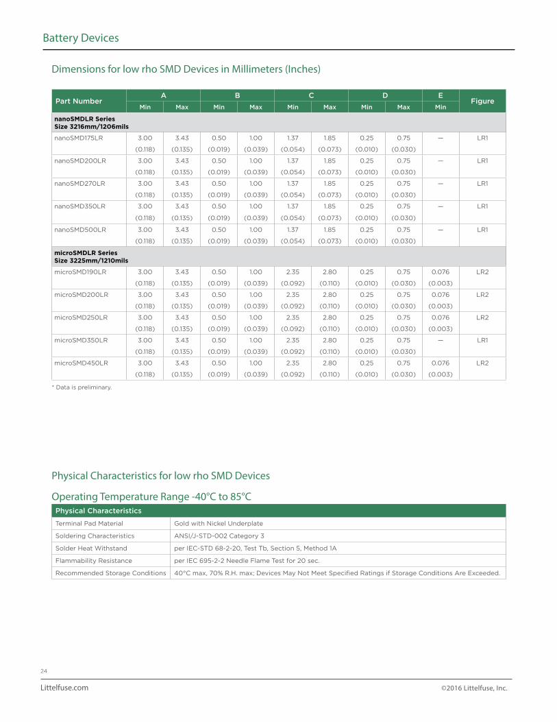
Dimensions for low rho SMD Devices in Millimeters (Inches)
Physical Characteristics for low rho SMD Devices
Operating Temperature Range -40°C to 85°CPhysical Characteristics
Terminal Pad Material Gold with Nickel Underplate
Soldering Characteristics ANSI/J-STD-002 Category 3
Solder Heat Withstand per IEC-STD 68-2-20, Test Tb, Section 5, Method 1A
Flammability Resistance per IEC 695-2-2 Needle Flame Test for 20 sec.
Recommended Storage Conditions 40°C max, 70% R.H. max; Devices May Not Meet Specified Ratings if Storage Conditions Are Exceeded.
Littelfuse.com ©2016 Littelfuse, Inc.
25
Battery Devices
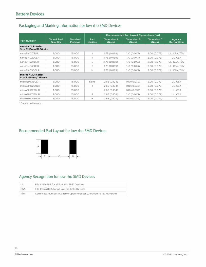
Recommended Pad Layout Figures [mm (in)]
Part NumberTape & Reel
QuantityStandardPackage
PartMarking
Dimension A (Nom)
Dimension B (Nom)
Dimension C (Nom)
Agency Recognition
nanoSMDLR SeriesSize 3216mm/1206mils
nanoSMD175LR 3,000 15,000 J 1.75 (0.069) 1.10 (0.043) 2.00 (0.079) UL, CSA, TÜV
nanoSMD200LR 3,000 15,000 T 1.75 (0.069) 1.10 (0.043) 2.00 (0.079) UL, CSA
nanoSMD270LR 3,000 15,000 L 1.75 (0.069) 1.10 (0.043) 2.00 (0.079) UL, CSA, TÜV
nanoSMD350LR 3,000 15,000 P 1.75 (0.069) 1.10 (0.043) 2.00 (0.079) UL, CSA, TÜV
nanoSMD500LR 3,000 15,000 H 1.75 (0.069) 1.10 (0.043) 2.00 (0.079) UL, CSA, TÜV
microSMDLR SeriesSize 3225mm/1210mils
microSMD190LR 3,000 15,000 None 2.65 (0.104) 1.00 (0.039) 2.00 (0.079) UL, CSA
microSMD200LR 3,000 15,000 T 2.65 (0.104) 1.00 (0.039) 2.00 (0.079) UL, CSA
microSMD250LR 3,000 15,000 L 2.65 (0.104) 1.00 (0.039) 2.00 (0.079) UL, CSA
microSMD350LR 3,000 15,000 P 2.65 (0.104) 1.10 (0.043) 2.00 (0.079) UL, CSA
microSMD450LR 3,000 15,000 H 2.65 (0.104) 1.00 (0.039) 2.00 (0.079) UL
* Data is preliminary.
Packaging and Marking Information for low rho SMD Devices
Recommended Pad Layout for low rho SMD Devices
Agency Recognition for low rho SMD Devices
UL File # E74889 for all low rho SMD Devices
CSA File # CA78165 for all low rho SMD Devices
TÜV Certificate Number Available Upon Request (Certified to IEC 60730-1)
A
B C B
Littelfuse.com ©2016 Littelfuse, Inc.
26
Battery Devices
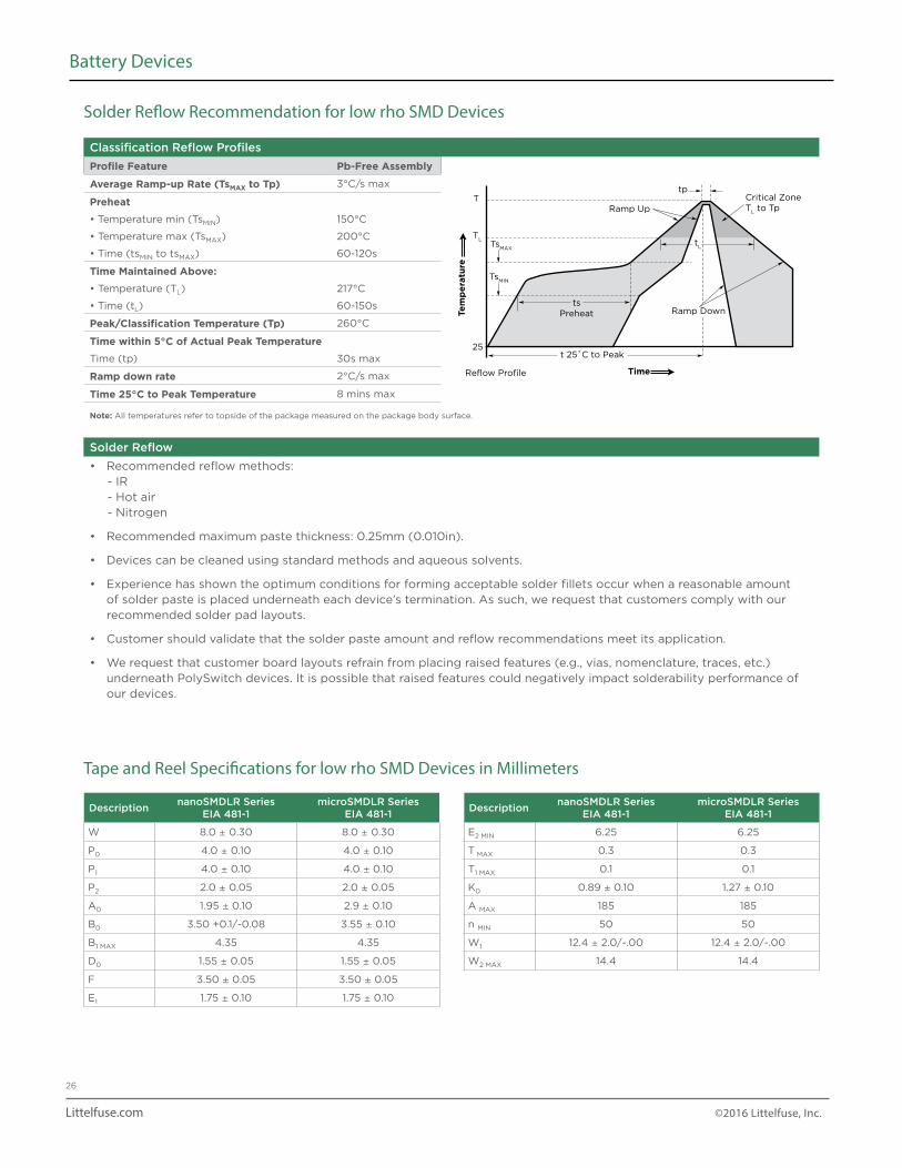
Solder Reflow Recommendation for low rho SMD Devices
Tape and Reel Specifications for low rho SMD Devices in Millimeters
Classification Reflow Profiles
Profile Feature Pb-Free Assembly
Average Ramp-up Rate (TsMAX to Tp) 3°C/s max
Preheat
• Temperature min (TsMIN) 150°C
• Temperature max (TsMAX) 200°C
• Time (tsMIN to tsMAX) 60-120s
Time Maintained Above:
• Temperature (TL) 217°C
• Time (tL) 60-150s
Peak/Classification Temperature (Tp) 260°C
Time within 5°C of Actual Peak Temperature
Time (tp) 30s max
Ramp down rate 2°C/s max
Time 25°C to Peak Temperature 8 mins max
Note: All temperatures refer to topside of the package measured on the package body surface.
Solder Reflow
• Recommended reflow methods: - IR - Hot air - Nitrogen
• Recommended maximum paste thickness: 0.25mm (0.010in).
• Devices can be cleaned using standard methods and aqueous solvents.
• Experience has shown the optimum conditions for forming acceptable solder fillets occur when a reasonable amount of solder paste is placed underneath each device’s termination. As such, we request that customers comply with our recommended solder pad layouts.
• Customer should validate that the solder paste amount and reflow recommendations meet its application.
• We request that customer board layouts refrain from placing raised features (e.g., vias, nomenclature, traces, etc.) underneath PolySwitch devices. It is possible that raised features could negatively impact solderability performance of our devices.
DescriptionnanoSMDLR Series
EIA 481-1microSMDLR Series
EIA 481-1
W 8.0 ± 0.30 8.0 ± 0.30
P0 4.0 ± 0.10 4.0 ± 0.10
P1 4.0 ± 0.10 4.0 ± 0.10
P2 2.0 ± 0.05 2.0 ± 0.05
A0 1.95 ± 0.10 2.9 ± 0.10
B0 3.50 +0.1/-0.08 3.55 ± 0.10
B1 MAX 4.35 4.35
D0 1.55 ± 0.05 1.55 ± 0.05
F 3.50 ± 0.05 3.50 ± 0.05
E1 1.75 ± 0.10 1.75 ± 0.10
DescriptionnanoSMDLR Series
EIA 481-1microSMDLR Series
EIA 481-1
E2 MIN 6.25 6.25
T MAX 0.3 0.3
T1 MAX 0.1 0.1
K0 0.89 ± 0.10 1.27 ± 0.10
A MAX 185 185
n MIN 50 50
W1 12.4 ± 2.0/-.00 12.4 ± 2.0/-.00
W2 MAX 14.4 14.4
Critical ZoneT
L to TpRamp Up
t 25˚C to Peak
Reflow Profile Time
Ramp Downts
Preheat
TsMAX
TL
Ttp
25
TsMIN
tL
Tem
pe
ratu
re
Littelfuse.com ©2016 Littelfuse, Inc.
27
Battery Devices
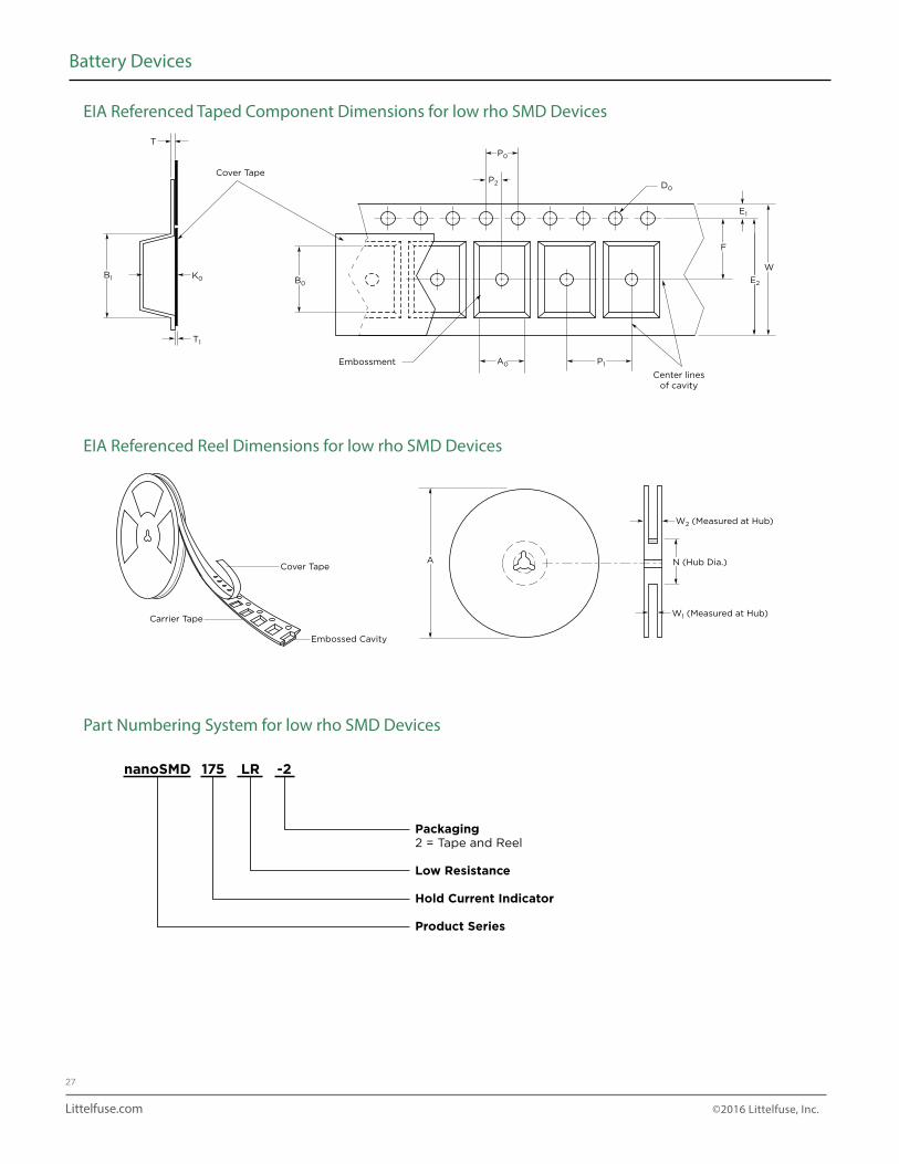
EIA Referenced Taped Component Dimensions for low rho SMD Devices
EIA Referenced Reel Dimensions for low rho SMD Devices
Part Numbering System for low rho SMD Devices
E1
D0
E2
F
W
Cover Tape
Embossment
Center linesof cavity
P2
P0
A0 P1
B0B1
T1
K0
T
ACover Tape
Embossed Cavity
Carrier Tape
N (Hub Dia.)
W2 (Measured at Hub)
W1 (Measured at Hub)
nanoSMD 175 LR -2
Packaging2 = Tape and Reel
Low Resistance
Hold Current Indicator
Product Series
Littelfuse.com ©2016 Littelfuse, Inc.
28
Battery Devices
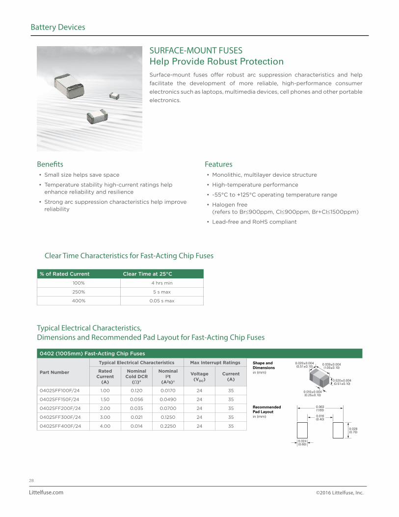
Clear Time Characteristics for Fast-Acting Chip Fuses
Typical Electrical Characteristics, Dimensions and Recommended Pad Layout for Fast-Acting Chip Fuses
% of Rated Current Clear Time at 25°C
100% 4 hrs min
250% 5 s max
400% 0.05 s max
0402 (1005mm) Fast-Acting Chip Fuses
Part Number
Typical Electrical Characteristics Max Interrupt Ratings
RatedCurrent
(A)
NominalCold DCR
(Ω)*
NominalI2t
(A2s)†
Voltage(VDC)
Current(A)
0402SFF100F/24 1.00 0.120 0.0170 24 35
0402SFF150F/24 1.50 0.056 0.0490 24 35
0402SFF200F/24 2.00 0.035 0.0700 24 35
0402SFF300F/24 3.00 0.021 0.1250 24 35
0402SFF400F/24 4.00 0.014 0.2250 24 35
0.063(1.60)
0.039±0.004(1.00±0.10)
0.020±0.004(0.51±0.10)
0.010±0.004(0.25±0.10)
0.020±0.004(0.51±0.10)
Shape andDimensionsin (mm)
RecommendedPad Layoutin (mm)
Shape andDimensionsin (mm)
RecommendedPad Layoutin (mm)
Shape andDimensionsin (mm)
RecommendedPad Layoutin (mm)
0.031±0.006(0.80±0.15)
0.063±0.008(1.60±0.20)
0.126±0.008(3.20±0.20)
0.043±0.008(1.10±0.20)
0.020±0.010(0.51±0.25)
0.031±0.006(0.80±0.15)
0.014±0.006(0.36±0.15)
0.063±0.006(1.60±0.15)
0.028(0.70)
0.024(0.60)
0.016(0.40)
0.110(2.80)
0.039(1.00)
0.043(1.09)
0.024(0.60)
0.173(4.40)
0.071(1.80)
0.057(1.45)
0.059(1.50)
SURFACE-MOUNT FUSESHelp Provide Robust ProtectionSurface-mount fuses offer robust arc suppression characteristics and help
facilitate the development of more reliable, high-performance consumer
electronics such as laptops, multimedia devices, cell phones and other portable
electronics.
Benefits• Small size helps save space
• Temperature stability high-current ratings help enhance reliability and resilience
• Strong arc suppression characteristics help improve reliability
Features• Monolithic, multilayer device structure
• High-temperature performance
• -55°C to +125°C operating temperature range
• Halogen free (refers to Br≤900ppm, CI≤900ppm, Br+CI≤1500ppm)
• Lead-free and RoHS compliant
Littelfuse.com ©2016 Littelfuse, Inc.
29
Battery Devices
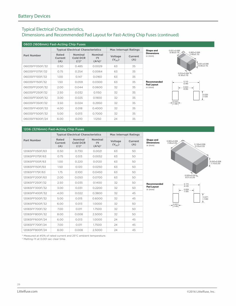
Typical Electrical Characteristics, Dimensions and Recommended Pad Layout for Fast-Acting Chip Fuses (continued)
0603 (1608mm) Fast-Acting Chip Fuses
Part Number
Typical Electrical Characteristics Max Interrupt Ratings
RatedCurrent
(A)
NominalCold DCR
(Ω)*
NominalI2t
(A2s)†
Voltage(VDC)
Current(A)
0603SFF050F/32 0.50 0.485 0.0029 63 35
0603SFF075F/32 0.75 0.254 0.0064 63 35
0603SFF100F/32 1.00 0.147 0.0160 63 35
0603SFF150F/32 1.50 0.059 0.0300 63 35
0603SFF200F/32 2.00 0.044 0.0600 32 35
0603SFF250F/32 2.50 0.032 0.1150 32 35
0603SFF300F/32 3.00 0.025 0.1900 32 35
0603SFF350F/32 3.50 0.024 0.2950 32 35
0603SFF400F/32 4.00 0.018 0.4000 32 35
0603SFF500F/32 5.00 0.013 0.7000 32 35
0603SFF600F/24 6.00 0.010 1.1250 24 35
1206 (3216mm) Fast-Acting Chip Fuses
Part Number
Typical Electrical Characteristics Max Interrupt Ratings
RatedCurrent
(A)
NominalCold DCR
(Ω)*
NominalI2t
(A2s)†
Voltage(VDC)
Current(A)
1206SFF050F/63 0.50 0.730 0.0021 63 50
1206SFF075F/63 0.75 0.513 0.0052 63 50
1206SFF100F/63 1.00 0.220 0.0120 63 50
1206SFF150F/63 1.50 0.120 0.0250 63 50
1206SFF175F/63 1.75 0.100 0.0450 63 50
1206SFF200F/63 2.00 0.050 0.0700 63 50
1206SFF250F/32 2.50 0.035 0.1400 32 50
1206SFF300F/32 3.00 0.031 0.2200 32 50
1206SFF400F/32 4.00 0.022 0.3800 32 45
1206SFF500F/32 5.00 0.015 0.6000 32 45
1206SFF600F/32 6.00 0.013 1.0000 32 50
1206SFF700F/32 7.00 0.011 1.7500 32 50
1206SFF800F/32 8.00 0.008 2.5000 32 50
1206SFF600F/24 6.00 0.013 1.0000 24 45
1206SFF700F/24 7.00 0.011 1.7500 24 45
1206SFF800F/24 8.00 0.008 2.5000 24 45
* Measured at #10% of rated current and 25°C ambient temperature.† Melting I2t at 0.001 sec clear time.
0.063(1.60)
0.039±0.004(1.00±0.10)
0.020±0.004(0.51±0.10)
0.010±0.004(0.25±0.10)
0.020±0.004(0.51±0.10)
Shape andDimensionsin (mm)
RecommendedPad Layoutin (mm)
Shape andDimensionsin (mm)
RecommendedPad Layoutin (mm)
Shape andDimensionsin (mm)
RecommendedPad Layoutin (mm)
0.031±0.006(0.80±0.15)
0.063±0.008(1.60±0.20)
0.126±0.008(3.20±0.20)
0.043±0.008(1.10±0.20)
0.020±0.010(0.51±0.25)
0.031±0.006(0.80±0.15)
0.014±0.006(0.36±0.15)
0.063±0.006(1.60±0.15)
0.028(0.70)
0.024(0.60)
0.016(0.40)
0.110(2.80)
0.039(1.00)
0.043(1.09)
0.024(0.60)
0.173(4.40)
0.071(1.80)
0.057(1.45)
0.059(1.50)
Littelfuse.com ©2016 Littelfuse, Inc.
30
Battery Devices
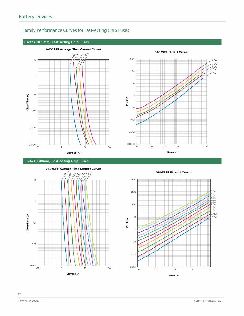
0402 (1005mm) Fast-Acting Chip Fuses
0603 (1608mm) Fast-Acting Chip Fuses
Family Performance Curves for Fast-Acting Chip Fuses
0.0010.0001 0.01 0.1 1 10
1,000
100
10
1
0.1
0.01
0.001
0.0001
I²t
(A²s
)
Time (s)
0402SFF I²t vs. t Curves
1.0A
1.5A2.0A
3.0A
4.0A
0.001 0.01 0.1 1 10
10000
1000
100
10
1
0.1
0.01
0.001
I²t
(A²s
)
Time (s)
0603SFF I2t vs. t Curves
0.5A
0.75A
1.0A1.5A
2.0A2.5A3.0A3.5A4.0A5.0A6.0A
0.1 101 100
Cle
ar-
Tim
e (
s)
10
1
0.1
0.01
0.001
0.0001
Current (A)
0402SFF Average Time Current Curves
1.0
A1.
5A
2.0
A3.0
A4
.0A
10
1
0.1
0.01
0.00110.1 10 100
Current (A)
Cle
ar-
Tim
e (
s)
0603SFF Average Time Current Curves
0.5
A0
.75A
1.0
A1.
5A
2.0
A2.5
A3.0
A3.5
A4
.0A
5.0
A6.0
A
Littelfuse.com ©2016 Littelfuse, Inc.
31
Battery Devices
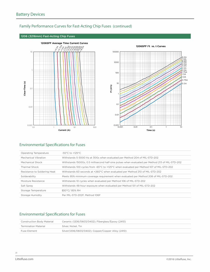
1206 (3216mm) Fast-Acting Chip Fuses
Family Performance Curves for Fast-Acting Chip Fuses (continued)
I2t
(A2s)
10000
1000
100
10
1
0.1
0.01
0.001
Time (s)
1206SFF I2t vs. t Curves
0.001 0.01 0.1 1 10
0.5A
0.75A
1.0A
1.5A1.75A2.0A2.5A3.0A4.0A5.0A6.0A7.0A8.0A
0.1 101 100
Cle
ar-
Tim
e (
s)
10
1
0.1
0.01
0.001
Current (A)
1206SFF Average Time Current Curves
0.5
A0
.75A
1.0
A1.
5A
1.75
A2.0
A2.5
A3.0
A4
.0A
5.0
A6.0
A7.
0A
8.0
A
Environmental Specifications for Fuses
Environmental Specifications for Fuses
Operating Temperature -55°C to +125°C
Mechanical Vibration Withstands 5-3000 Hz at 30Gs when evaluated per Method 204 of MIL-STD-202
Mechanical Shock Withstands 1500Gs, 0.5 millisecond half-sine pulses when evaluated per Method 213 of MIL-STD-202
Thermal Shock Withstands 100 cycles from -65°C to +125°C when evaluated per Method 107 of MIL-STD-202
Resistance to Soldering Heat Withstands 60 seconds at +260°C when evaluated per Method 210 of MIL-STD-202
Solderability Meets 95% minimum coverage requirement when evaluated per Method 208 of MIL-STD-202
Moisture Resistance Withstands 10 cycles when evaluated per Method 106 of MIL-STD-202
Salt Spray Withstands 48-hour exposure when evaluated per Method 101 of MIL-STD-202
Storage Temperature 30°C/ 85% RH
Storage Humidity Per MIL-STD-202F, Method 106F
Construction Body Material Ceramic (1206/0603/0402); Fiberglass/Epoxy (2410)
Termination Material Silver, Nickel, Tin
Fuse Element Silver(1206/0603/0402); Copper/Copper Alloy (2410)

Littelfuse.com ©2016 Littelfuse, Inc.
32
Battery Devices
Thermal Derating Current for Fuses
Electrical Specifications for Fuses
Insulation Resistance after Opening
20,000Ω minimum @ rated voltage. Fuse clearing under low-voltage conditions may result in lower post-clearing insulation values. Under normal fault conditions Littelfuse fuses help provide sufficient insulation resistance for circuit protection.
Current Carrying Capacity Withstands 100% rated current at +25°C ambient for 4 hours when evaluated per MIL-PRF-23419.
1206/0603/0402 SeriesTemperature Effect on Current Rating
2410 SeriesTemperature Effect on Current Rating
% D
era
tin
g
% D
era
tin
g
10510095908580757065605550454035302520151050
110
105
100
95
90
85
80
75
70
65
60
55
50
Maximum Operating Temperature (˚C) Maximum Operating Temperature (˚C)
-55 -35 -15 5 25 45 65 85 105 125 145 -55 -35 -15 5 25 45 65 85 105 125
Packaging Information for Fuses
SizeReel
Quantity(pcs)
Reel Diameter
Reel WidthCarrier
Tape SizeTape Type
Reels per Outside
Shipment Box
Outside ShipmentBoxes per Overpack
0402 (1005) 10,000178mm
White Plastic9.0 ± 0.5mm 8.00 ± 0.10mm Paper 5 1 to 10
0603 (1608) 4,000178mm
White Plastic9.0 ± 0.5mm 8.00 ± 0.10mm Paper 5 1 to 10
0603SFV (1608) 6,000178mm
White Plastic9.0 ± 0.5mm 8.00 ± 0.10mm Paper 5 1 to 10
1206 (3216) 3,000178mm
White Plastic9.0 ± 0.5mm 8.00 ± 0.10mm Plastic 5 1 to 10
2410 (6125) 2,000178mm
White Plastic13.4 ± 0.5mm 12.00 ± 0.10mm Plastic 4 1 to 10
Littelfuse.com ©2016 Littelfuse, Inc.
33
Battery Devices
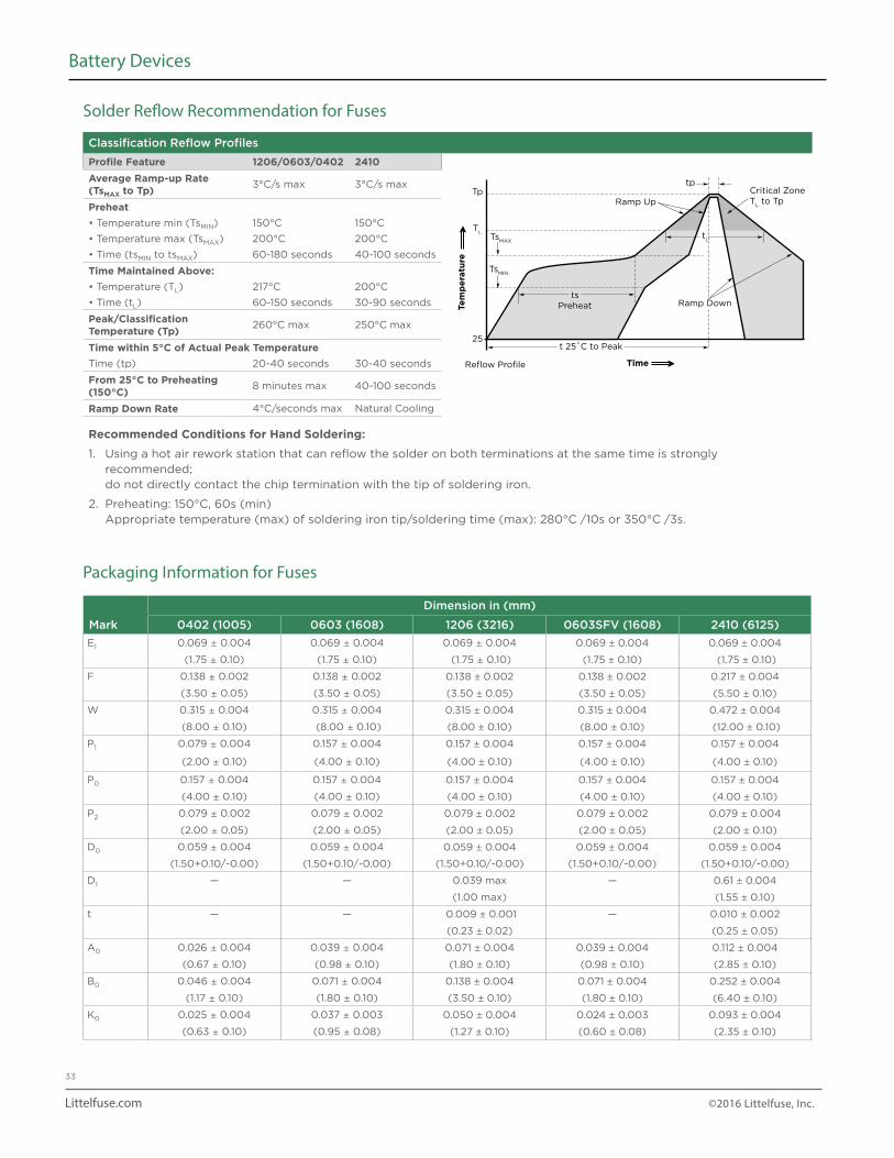
Solder Reflow Recommendation for Fuses
Classification Reflow Profiles
Profile Feature 1206/0603/0402 2410Average Ramp-up Rate (TsMAX to Tp) 3°C/s max 3°C/s max
Preheat• Temperature min (TsMIN) 150°C 150°C
• Temperature max (TsMAX) 200°C 200°C
• Time (tsMIN to tsMAX) 60-180 seconds 40-100 seconds
Time Maintained Above:• Temperature (TL) 217°C 200°C
• Time (tL) 60-150 seconds 30-90 seconds
Peak/Classification Temperature (Tp) 260°C max 250°C max
Time within 5°C of Actual Peak TemperatureTime (tp) 20-40 seconds 30-40 seconds
From 25°C to Preheating (150°C) 8 minutes max 40-100 seconds
Ramp Down Rate 4°C/seconds max Natural Cooling
Recommended Conditions for Hand Soldering:
1. Using a hot air rework station that can reflow the solder on both terminations at the same time is strongly recommended; do not directly contact the chip termination with the tip of soldering iron.
2. Preheating: 150°C, 60s (min) Appropriate temperature (max) of soldering iron tip/soldering time (max): 280°C /10s or 350°C /3s.
Critical ZoneT
L to TpRamp Up
t 25˚C to Peak
Reflow Profile Time
Ramp Downts
Preheat
TsMAX
TL
Tptp
25
TsMIN
tL
Tem
pe
ratu
re
Packaging Information for Fuses
Mark
Dimension in (mm)
0402 (1005) 0603 (1608) 1206 (3216) 0603SFV (1608) 2410 (6125)
E1 0.069 ± 0.004 0.069 ± 0.004 0.069 ± 0.004 0.069 ± 0.004 0.069 ± 0.004
(1.75 ± 0.10) (1.75 ± 0.10) (1.75 ± 0.10) (1.75 ± 0.10) (1.75 ± 0.10)
F 0.138 ± 0.002 0.138 ± 0.002 0.138 ± 0.002 0.138 ± 0.002 0.217 ± 0.004
(3.50 ± 0.05) (3.50 ± 0.05) (3.50 ± 0.05) (3.50 ± 0.05) (5.50 ± 0.10)
W 0.315 ± 0.004 0.315 ± 0.004 0.315 ± 0.004 0.315 ± 0.004 0.472 ± 0.004
(8.00 ± 0.10) (8.00 ± 0.10) (8.00 ± 0.10) (8.00 ± 0.10) (12.00 ± 0.10)
P1 0.079 ± 0.004 0.157 ± 0.004 0.157 ± 0.004 0.157 ± 0.004 0.157 ± 0.004
(2.00 ± 0.10) (4.00 ± 0.10) (4.00 ± 0.10) (4.00 ± 0.10) (4.00 ± 0.10)
P0 0.157 ± 0.004 0.157 ± 0.004 0.157 ± 0.004 0.157 ± 0.004 0.157 ± 0.004
(4.00 ± 0.10) (4.00 ± 0.10) (4.00 ± 0.10) (4.00 ± 0.10) (4.00 ± 0.10)
P2 0.079 ± 0.002 0.079 ± 0.002 0.079 ± 0.002 0.079 ± 0.002 0.079 ± 0.004
(2.00 ± 0.05) (2.00 ± 0.05) (2.00 ± 0.05) (2.00 ± 0.05) (2.00 ± 0.10)
D0 0.059 ± 0.004 0.059 ± 0.004 0.059 ± 0.004 0.059 ± 0.004 0.059 ± 0.004
(1.50+0.10/-0.00) (1.50+0.10/-0.00) (1.50+0.10/-0.00) (1.50+0.10/-0.00) (1.50+0.10/-0.00)
D1 — — 0.039 max — 0.61 ± 0.004
(1.00 max) (1.55 ± 0.10)
t — — 0.009 ± 0.001 — 0.010 ± 0.002
(0.23 ± 0.02) (0.25 ± 0.05)
A0 0.026 ± 0.004 0.039 ± 0.004 0.071 ± 0.004 0.039 ± 0.004 0.112 ± 0.004
(0.67 ± 0.10) (0.98 ± 0.10) (1.80 ± 0.10) (0.98 ± 0.10) (2.85 ± 0.10)
B0 0.046 ± 0.004 0.071 ± 0.004 0.138 ± 0.004 0.071 ± 0.004 0.252 ± 0.004
(1.17 ± 0.10) (1.80 ± 0.10) (3.50 ± 0.10) (1.80 ± 0.10) (6.40 ± 0.10)
K0 0.025 ± 0.004 0.037 ± 0.003 0.050 ± 0.004 0.024 ± 0.003 0.093 ± 0.004
(0.63 ± 0.10) (0.95 ± 0.08) (1.27 ± 0.10) (0.60 ± 0.08) (2.35 ± 0.10)
Littelfuse.com ©2016 Littelfuse, Inc.
34
Battery Devices
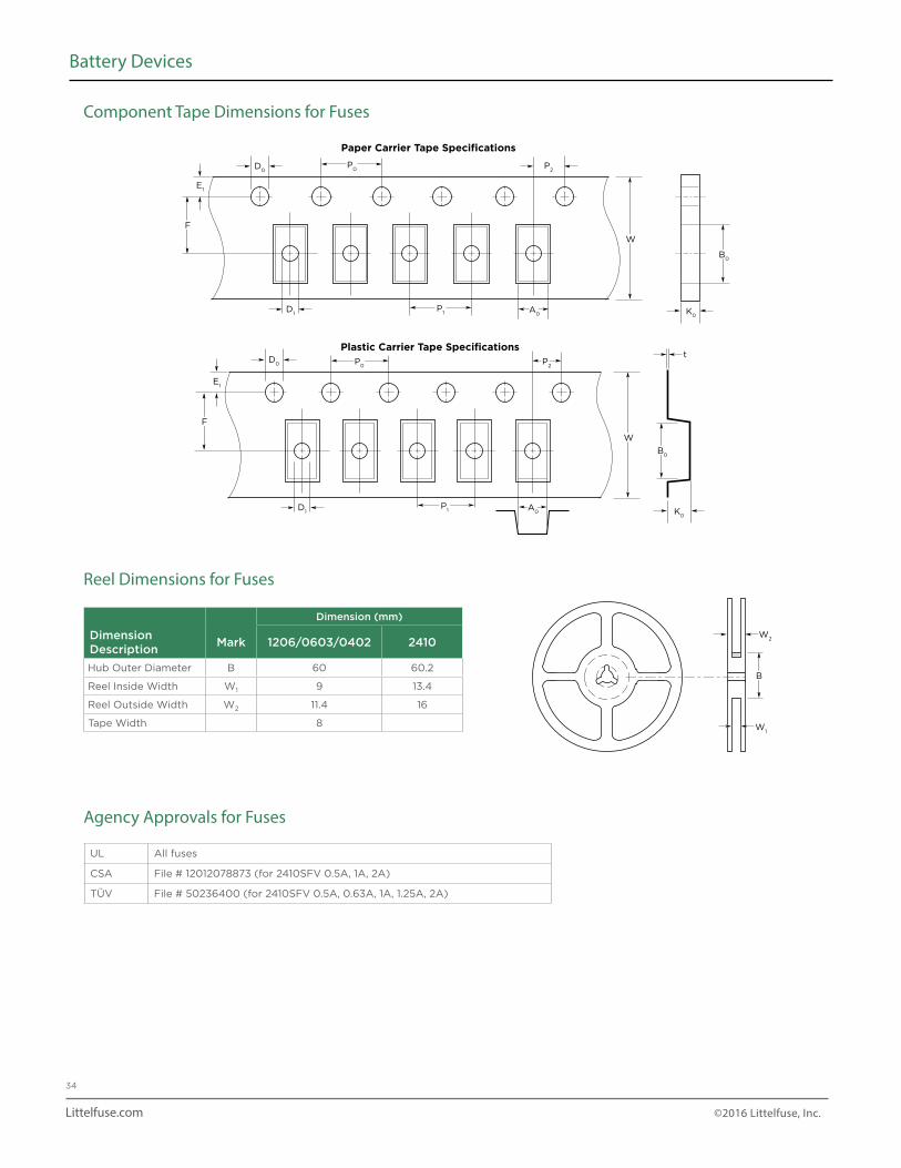
Component Tape Dimensions for Fuses
P0
P0
P2
P1
P1
E1
E1
F
F
W
W
t
D0
D0
D1
D1
A0
A0
B0
K0
K0
B0
P2
Paper Carrier Tape Specifications
Plastic Carrier Tape Specifications
Reel Dimensions for Fuses
Agency Approvals for Fuses
Dimension (mm)
DimensionDescription
Mark 1206/0603/0402 2410
Hub Outer Diameter B 60 60.2
Reel Inside Width W1 9 13.4
Reel Outside Width W2 11.4 16
Tape Width 8
UL All fuses
CSA File # 12012078873 (for 2410SFV 0.5A, 1A, 2A)
TÜV File # 50236400 (for 2410SFV 0.5A, 0.63A, 1A, 1.25A, 2A)
B
W2
W1
Littelfuse.com ©2016 Littelfuse, Inc.
35
Battery Devices
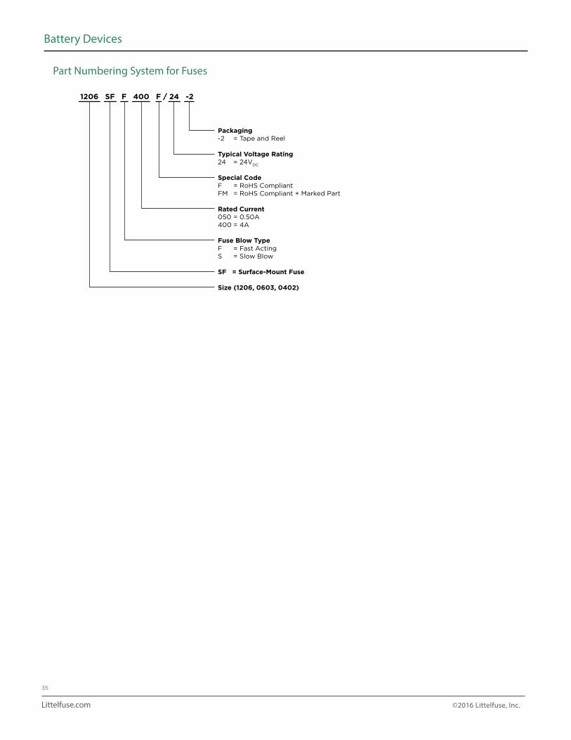
Part Numbering System for Fuses
1206 SF F 400 F / 24 -2
Packaging-2 = Tape and Reel
Typical Voltage Rating24 = 24VDC
Special CodeF = RoHS CompliantFM = RoHS Compliant + Marked Part
Rated Current050 = 0.50A400 = 4A
Fuse Blow TypeF = Fast ActingS = Slow Blow
SF = Surface-Mount Fuse
Size (1206, 0603, 0402)
Littelfuse.com ©2016 Littelfuse, Inc.
36
Battery Devices
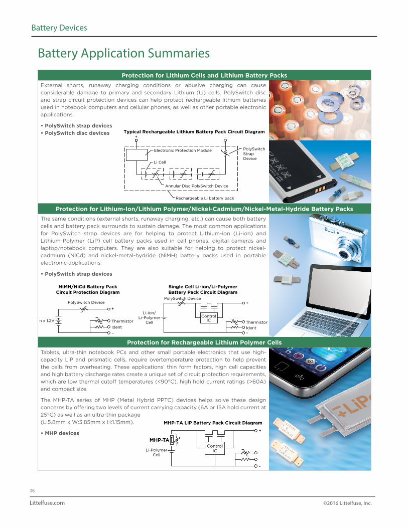
Protection for Lithium Cells and Lithium Battery PacksExternal shorts, runaway charging conditions or abusive charging can cause
considerable damage to primary and secondary Lithium (Li) cells. PolySwitch disc
and strap circuit protection devices can help protect rechargeable lithium batteries
used in notebook computers and cellular phones, as well as other portable electronic
applications.
• PolySwitch strap devices• PolySwitch disc devices
Protection for Lithium-Ion/Lithium Polymer/Nickel-Cadmium/Nickel-Metal-Hydride Battery PacksThe same conditions (external shorts, runaway charging, etc.) can cause both battery
cells and battery pack surrounds to sustain damage. The most common applications
for PolySwitch strap devices are for helping to protect Lithium-ion (Li-ion) and
Lithium-Polymer (LiP) cell battery packs used in cell phones, digital cameras and
laptop/notebook computers. They are also suitable for helping to protect nickel-
cadmium (NiCd) and nickel-metal-hydride (NiMH) battery packs used in portable
electronic applications.
• PolySwitch strap devices
Protection for Rechargeable Lithium Polymer CellsTablets, ultra-thin notebook PCs and other small portable electronics that use high-
capacity LiP and prismatic cells, require overtemperature protection to help prevent
the cells from overheating. These applications’ thin form factors, high cell capacities
and high battery discharge rates create a unique set of circuit protection requirements,
which are low thermal cutoff temperatures (<90°C), high hold current ratings (>60A)
and compact size.
The MHP-TA series of MHP (Metal Hybrid PPTC) devices helps solve these design
concerns by offering two levels of current carrying capacity (6A or 15A hold current at
25°C) as well as an ultra-thin package
(L:5.8mm x W:3.85mm x H:1.15mm).
• MHP devices
+ –
Li Cell
PolySwitchStrapDevice
Annular Disc PolySwitch Device
Rechargeable Li battery pack
. . .
Electronic Protection Module
Typical Rechargeable Lithium Battery Pack Circuit Diagram
ControlIC
Li-ion/Li-Polymer
Cell
+
Thermistor
Ident–
PolySwitch Device
n x 1.2V
+
Thermistor
PolySwitch Device
Ident
–
NiMH/NiCd Battery Pack Circuit Protection Diagram
Single Cell Li-ion/Li-Polymer Battery Pack Circuit Diagram
ControlICLi-Polymer
Cell
MHP-TA
+
–
MHP-TA LiP Battery Pack Circuit Diagram
Battery Application Summaries
Littelfuse.com ©2016 Littelfuse, Inc.
37
Battery Devices
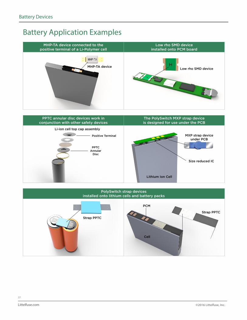
MHP-TA device connected to the positive terminal of a Li-Polymer cell
Low rho SMD device installed onto PCM board
PPTC annular disc devices work in conjunction with other safety devices
The PolySwitch MXP strap device is designed for use under the PCB
PolySwitch strap devices installed onto lithium cells and battery packs
Low rho SMD deviceMHP-TA device
Strap PPTC
PCM
Strap PPTC
Cell
Li-ion cell top cap assembly
MXP strap deviceunder PCB
Size reduced IC
Lithium Ion Cell
Positive Terminal
PPTCAnnular
Disc
Battery Application Examples
Littelfuse.com ©2016 Littelfuse, Inc.
38
Battery Devices
Notice:
Information furnished is believed to be accurate and reliable. However, users should independently evaluate the suitability of and test each product selected for their own applications. Littelfuse products are not designed for, and shall not be used for, any purpose (including, without limitation, military, aerospace, medical, life-saving, life-sustaining or nuclear facility applications, devices intended for surgical implant into the body, or any other application in which the failure or lack of desired operation of the product may result in personal injury, death, or property damage) other than those expressly set forth in applicable Littelfuse product documentation. Warranties granted by Littelfuse shall be deemed void for products used for any purpose not expressly set forth in applicable Littelfuse documentation. Littelfuse shall not be liable for any claims or damages arising out of products used in applications not expressly intended by Littelfuse as set forth in applicable Littelfuse documentation. The sale and use of Littelfuse products is subject to Littelfuse Terms and Conditions of Sale, unless otherwise agreed by Littelfuse.