battle command on the move - dodccrp.org · chief kobsar went to dataline, ... battle command on...
TRANSCRIPT
Battle Command on the Move
Authors: Rebecca Morley Chief Joseph Kobsar
POC: Rebecca Morley AMSRD-CER-C2-BCS-MD
Building 2700 Ft. Monmouth, NJ 07703
Telephone: (732) 532-8927 Fax: (732) 532-8929
- 1 -
1. Abstract Battle Command on the Move (BCOTM) is a revolutionary capability that provides current and future combined arms commanders all of the information resident in their command posts, and the required communications necessary to command and control their combined arms team on the move, or at a short halt, from any vantage point on the joint battlefield. The purpose of the BCOTM effort was to convert five M-7 Bradley Fire Support Team (BFIST) vehicles into BCOTM systems. Three operator workstations and an extensive Mission Equipment Package (MEP) were integrated into the five BFIST platforms to provide a common operational picture and enable Situational Understanding (SU) while on the move. The integration team consisted of three groups who worked together for 2 months to complete the system from the concept until the final hand off to the 4th Infantry Division (ID), Fort Hood, TX. The program was extremely successful and has led to further advancements in battle command on the move.
2. Background
2.1. The Current Battle Command Currently, command and control is conducted from Command Posts (CP). There are three basic areas of battle command; the current fight, future planning, and support. The current fight is the responsibility of the Division Tactical (DTAC) CP, which is usually small and mobile and allows the commander to plan and monitor the battle from a remote location. The DTAC travels with the Calvary and is set up once arriving at the battlefield. The next area of battle command is the deep battle planning and intelligence. This planning is conducted from a much larger command post, Division Main (DMAIN). DMAIN performs functions such as coordination, synchronization, prioritization, and allocation of resources and is not as mobile as the DTAC. Finally, support functions are run from the Rear CP, which includes sustainment, maintenance, movement control, and fire support. The Rear CP handles issues such as fuel and ammunition dumps, field hospitals, and any other support or maintenance needed while in the field.1
2.2. Problems With This Method One of the problems with this battle command system is that the commander has little communication while in the field. The planning occurs at the Command Post or Tactical Operation Center (TOC). Once the battle begins, the Commander leaves the CP and moves forward to stay engaged. The commander has limited communication while in the field, usually just a Line-Of-Sight (LOS) radio and a map (with the recent advent of Blue Force Tracking, the Commander has more SU), making it difficult to follow and control all events as they happen. Battles rarely occur as planned, therefore, the staff will attempt to keep the Commander apprised of changes and give him recommendations through voice comms. The commander really needs the same resources that are available to him in the CP in order to view the entire battlefield, including changes as they happen, and to make split-second decisions while on the battlefield. This is what BCOTM offers.
- 2 -
Another setback is the time required to set up the command posts. The unit may have to wait for DTAC to arrive and then have to set up the command post before the battle, which could delay the operation by hours.
3. The Proposed System
3.1. The Initial Concept The initial concept first developed in Germany when General Codi gave General Wallace Command and Control Vehicles (C2Vs) to go to war with in 1993 from a canceled program years earlier. General Wallace tasked Chief Kobsar to investigate how much effort and funding it would take to convert the C2V into a command and control vehicle. Chief Kobsar went to Dataline, who had done similar work for General Bell, however the equipment was installed into an aircraft. Together with Dataline, PM platforms, and their supporting contractors, Kobsar produced a quote that was cheaper than bids from large companies such as Lockheed Martin and General Dynamics, therefore Dataline got the contract. The vehicle was targeted for the brigade and division commanders and would be the commanders’ Digital Assault Command Post (ACP), allowing them to plan operations, communicates intentions, share information, and track progress while untethered from the command post. The C2V would provide a common operational picture and enable Situational Understanding (SU) while on the move, allowing the commanders to be present at the decisive point on the battlefield.
3.2. Previous Battle Command Vehicles Battle Command on the Move (BCOTM) is not a new concept to the army. The M4 Command and Control Vehicle (C2V) was a powerful weapon in Operational Iraqi Freedom. The C2V was first was introduced in 1993 as an armored vehicle that provides a tactical command post for mobile armored operations. The platform used was a tracked vehicle, mounted on the base of a Multiple Rocket Launcher System (MRLS), and was therefore powered by the same 600 horsepower drive train currently used in the Bradley. The C2V housed 4 command stations that can access the Army Battle Command System (ABCS), providing the ability to support command and control functions while on-the-move. The next advancement in this technology was the Bradley Commander’s Vehicle (BCV), which transpired in 1995. The BCV effort was to provide a Tactical Operations Center (TOC) to the 4th Infantry Division’s 1st and 2nd brigade for experimental purposes only. The BCV housed three workstations facing sideways and was configured to host the digitized devices necessary to execute the battle by using software such as Maneuver Control System (MCS), All Source Analysis System (ASAS), and Force XXI Battle Command Brigade and Below (FBCB2).
The next step towards “on-the-move” capabilities was the Pandur vehicle in 2001. The Pandur’s intent was to participate in the 4th ID’s Division Capstone Exercise (DCX II) in order “to revitalize the Army’s requirement for a commander’s ground vehicle that
- 3 -
enables execution of battle command and leadership un-tethered from static command posts.”2 The objectives were to develop and demonstrate a light armored mobile surrogate capability that supports command and control on-the-move by using radio data. This system was unique in providing a Multiple Processing Unit (MPU) and Keyboard-Video-Mouse Switch (KVM) that allowed the commander and his battle captains access to any of the heavy Battlefield Functional Areas (BFAs) hosted on the MPU via the KVM and their workstation. The final phase in battle command on the move was the Light Armored Vehicle (LAV). The Pandur was returned to its owner after completing DCX II, therefore the Mission Equipment Package was moved into two LAVs that were borrowed from the Marines. These vehicles were used in an operational environment at the National Training Center (NTC) by 4ID. The Operation Needs Statement required to build the Bradleys was written by 4ID as a result of their experience with the BCOTM system at the NTC.
4. Delivery Schedule The BCOTM program's main driving factor was the schedule due to the threat of war in Southwest Asia. The initial discussion of the program began on October 16, 2002, with a completion date of January 17th, 2003. Due to availability of a Bradley vehicle, the program kick-off was delayed until November 6, 2002, however the delivery date of the system remained the same. This only gave two months for design, engineering, fabrication, and system integration.
5. Personnel Three groups were involved in the design and integration effort of the BCOTM. PM Bradley’s prime contractor United Defense Limited Partnership (UDLP) was responsible for the chassis and final integration of the system. PM Platforms, with the Command and Control Directorate (C2D) of The US Army Research, Development and Engineering Command – Communications-Electronics Research, Development and Engineering Center (RDECOM-CERDEC) at Ft. Monmouth and Lockheed Martin Technology Services, Fort Hood, TX, was responsible for the architecture and the Mission Equipment Package (MEP). All three participating groups have prior experience in battle command systems. UDLP was the contractor for the C2V, C2D designed and integrated the BCV, and both C2D and Lockheed Martin designed and integrated the Pandur and LAV vehicles. Geographic separation was a foreseen problem in the design process, especially with the demanding schedule, therefore C2D relocated to San Jose, California for a month to work in conjunction with UDLP on the design and engineering effort.
6. Team Effort
6.1. Goals
- 4 -
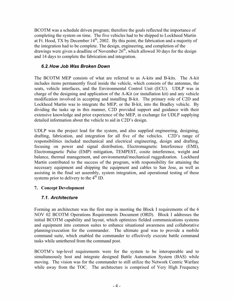
BCOTM was a schedule driven program; therefore the goals reflected the importance of completing the system on time. The five vehicles had to be shipped to Lockheed Martin at Ft. Hood, TX by December 14th, 2002. By this point, the fabrication and a majority of the integration had to be complete. The design, engineering, and completion of the drawings were given a deadline of November 26th, which allowed 30 days for the design and 14 days to complete the fabrication and integration.
6.2. How Job Was Broken Down The BCOTM MEP consists of what are referred to as A-kits and B-kits. The A-kit includes items permanently fixed inside the vehicle, which consists of the antennas, the seats, vehicle interfaces, and the Environmental Control Unit (ECU). UDLP was in charge of the designing and application of the A-Kit (or installation kit) and any vehicle modification involved in accepting and installing B-kit. The primary role of C2D and Lockheed Martin was to integrate the MEP, or the B-kit, into the Bradley vehicle. By dividing the tasks up in this manner, C2D provided support and guidance with their extensive knowledge and prior experience of the MEP, in exchange for UDLP supplying detailed information about the vehicle to aid in C2D’s design. UDLP was the project lead for the system, and also supplied engineering, designing, drafting, fabrication, and integration for all five of the vehicles. C2D’s range of responsibilities included mechanical and electrical engineering, design and drafting, focusing on power and signal distribution, Electromagnetic Interference (EMI), Electromagnetic Pulse (EMP) mitigation, TEMPEST, cosite interference, weight and balance, thermal management, and environmental/mechanical ruggedization. Lockheed Martin contributed to the success of the program, with responsibility for attaining the necessary equipment and shipping the equipment and cables to San Jose, as well as assisting in the final set assembly, system integration, and operational testing of these systems prior to delivery to the 4th ID.
7. Concept Development
7.1. Architecture Forming an architecture was the first step in meeting the Block I requirements of the 6 NOV 02 BCOTM Operations Requirements Document (ORD). Block I addresses the initial BCOTM capability and layout, which optimizes fielded communications systems and equipment into common suites to enhance situational awareness and collaborative planning/execution for the commander. The ultimate goal was to provide a mobile command suite, which enabled the commander to effectively execute battle command tasks while untethered from the command post. BCOTM’s top-level requirements were for the system to be interoperable and to simultaneously host and integrate designed Battle Automation System (BAS) while moving. The vision was for the commander to still utilize the Network Centric Warfare while away from the TOC. The architecture is comprised of Very High Frequency
- 5 -
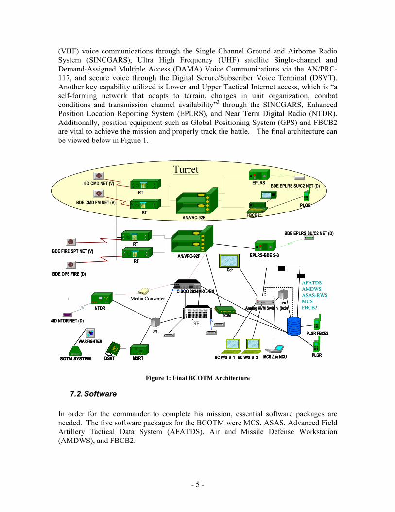
(VHF) voice communications through the Single Channel Ground and Airborne Radio System (SINCGARS), Ultra High Frequency (UHF) satellite Single-channel and Demand-Assigned Multiple Access (DAMA) Voice Communications via the AN/PRC-117, and secure voice through the Digital Secure/Subscriber Voice Terminal (DSVT). Another key capability utilized is Lower and Upper Tactical Internet access, which is “a self-forming network that adapts to terrain, changes in unit organization, combat conditions and transmission channel availability”3 through the SINCGARS, Enhanced Position Location Reporting System (EPLRS), and Near Term Digital Radio (NTDR). Additionally, position equipment such as Global Positioning System (GPS) and FBCB2 are vital to achieve the mission and properly track the battle. The final architecture can be viewed below in Figure 1.
Figure 1: Final BCOTM Architecture
7.2. Software In order for the commander to complete his mission, essential software packages are needed. The five software packages for the BCOTM were MCS, ASAS, Advanced Field Artillery Tactical Data System (AFATDS), Air and Missile Defense Workstation (AMDWS), and FBCB2.
AN/VRC-92FRT
1 2 34 5 67 8 9* #0
RTBDE FIRE SPT NET (V)
BDE OPS FIRE (D)
NTDR
4ID NTDR NET (D)
UPS
EPLRS-BDE S-3
BDE EPLRS SU/C2 NET (D)
BDE EPLRS SU/C2 NET (D)
AN/VRC-92F
RT
1 24 57 8*
RT
EPLRS4ID CMD NET (V)
BDE CMD FM NET (V) PLGR
FBCB2
Turret
Media Converter
1 2 34 5 67 8 9* #0
36
9
1 2 34 5 67 8 9* #0
FH MUX
SEP- CMD GP
PLGR
AFATDSAMDWSASAS-RWSMCS FBCB2
PLGR FBCB2
Analog KVM Switch (8x8)
Cdr
BC W/S # 1 BC W/S # 2MSRTDSVTSOTM SYSTEM
SOTM SYSTEM
WARFIGHTER
MCS Lite NCUTAU x2
TCIM
UPS
CISCO 2924M-XL-EN
AN/VRC-92FRT
1 2 34 5 67 8 9* #0
RTBDE FIRE SPT NET (V)
BDE OPS FIRE (D)
NTDR
4ID NTDR NET (D)
UPSUPS
EPLRS-BDE S-3EPLRS-BDE S-3
BDE EPLRS SU/C2 NET (D)
BDE EPLRS SU/C2 NET (D)
AN/VRC-92F
RT
1 24 57 8*
RT
1 24 57 8*
RT
EPLRS4ID CMD NET (V)
BDE CMD FM NET (V) PLGRPLGR
FBCB2
Turret
Media Converter
1 2 34 5 67 8 9* #0
36
9
1 2 34 5 67 8 9* #0
1 2 34 5 67 8 9* #0
FH MUXFH MUX
SEP- CMD GP
PLGRPLGR
AFATDSAMDWSASAS-RWSMCS FBCB2
PLGR FBCB2PLGR FBCB2
Analog KVM Switch (8x8)
Cdr
BC W/S # 1 BC W/S # 2MSRTDSVT MSRTMSRTDSVTSOTM SYSTEM
SOTM SYSTEMSOTM SYSTEMSOTM SYSTEM
SOTM SYSTEM
WARFIGHTERWARFIGHTER
MCS Lite NCUMCS Lite NCUTAU x2TAU x2
TCIM
UPSUPS
CISCO 2924M-XL-EN
SE
- 6 -
The combination of all five software programs helps the commander make educated decisions on the battlefield. “MCS automates the creation and distribution of the command tactical picture of the battlefield as well as operation plans and orders.”4¶2 MCS also integrates information from other battlefield operations to provide accurate status information. FBCB2 provides a situational awareness and command and control as well. It facilitates a flow of battle command information and positioning across the battle space by using the Tactical Internet network and GPS transponders located on ground vehicles. Enemy information is added to the common picture through intelligence staffs by using ASAS. ASAS is the Intel fusion system that provides intelligence information for generating and tracking enemy positions. AFATDS is used to process ammunition and other related information to coordinate and optimize the use of all fire comport assets. The commander uses AFATDS to dominate the battlefield by providing the right mix of firing platforms and munitions to defeat enemy targets. Finally, AMDWS is used to integrate the different software programs into one source of information. AMDWS is the primary tool for monitoring and managing operations. It combines information received from MCS, ASAS, and aids the commander with the overall picture for planning and mission control purposes.
7.3. Key Hardware The hardware used in the system was just as important as the software. The hardware chosen had to meet all of the functional requirements for communication and planning, as well as meet the spatial requirements of the Bradley. The designers and engineers arranged the hardware defined by the architecture into the vehicle, which presented quite a challenge. The key piece of hardware used was a 6-slice Multiprocessor Unit (MPU). The MPU is a configurable platform that consolidates six single-board computer modules into a single chassis. The software discussed in section 7.2 was burned into hard drives, instead of mounting a separate computer for each application. By utilizing this technology, more capabilities could be installed into the limited space claim of the hull. Another key piece of hardware was the Keyboard-Video-Mouse (KVM) switch. This switch allows for the operators to toggle between and share information from the Army Battle Command System (ABCS) software suite.
8. Configuration As mentioned in section 7.3, the Bradley has limited room in the hull; therefore the spatial constraints drove the location of the equipment. The second driving factor was the vibration of the vehicle. UDLP and C2D worked together to analyze where the majority of the vibration was in the vehicle and how much vibration the equipment could withstand. The third driving factor was the heat dissipation. The most important items,
- 7 -
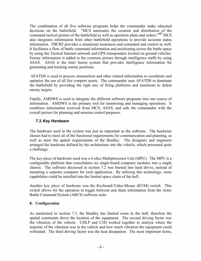
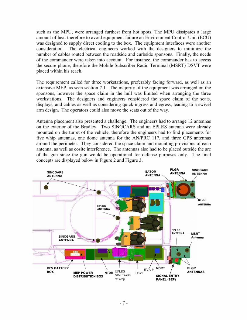
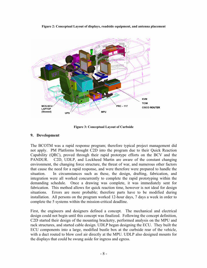
such as the MPU, were arranged furthest from hot spots. The MPU dissipates a large amount of heat therefore to avoid equipment failure an Environment Control Unit (ECU) was designed to supply direct cooling to the box. The equipment interfaces were another consideration. The electrical engineers worked with the designers to minimize the number of cables routed between the roadside and curbside sponsons. Finally, the needs of the commander were taken into account. For instance, the commander has to access the secure phone; therefore the Mobile Subscriber Radio Terminal (MSRT) DSVT were placed within his reach. The requirement called for three workstations, preferably facing forward, as well as an extensive MEP, as seen section 7.1. The majority of the equipment was arranged on the sponsons, however the space claim in the hull was limited when arranging the three workstations. The designers and engineers considered the space claim of the seats, displays, and cables as well as considering quick ingress and egress, leading to a swivel arm design. The operators could also move the seats out of the way. Antenna placement also presented a challenge. The engineers had to arrange 12 antennas on the exterior of the Bradley. Two SINGCARS and an EPLRS antenna were already mounted on the turret of the vehicle, therefore the engineers had to find placements for five whip antennas, one dome antenna for the AN/PRC 117, and three GPS antennas around the perimeter. They considered the space claim and mounting provisions of each antenna, as well as cosite interference. The antennas also had to be placed outside the arc of the gun since the gun would be operational for defense purposes only. The final concepts are displayed below in Figure 2 and Figure 3.
SIGNAL ENTRY PANEL (SEP)
PLGR ANTENNAS
BFV BATTERY BOX
MSRT Antenna
EPLRS ANTENNA
PLGR ANTENNA
MEP POWER DISTRIBUTION BOX
NTDR MSRT
SATOM ANTENNA
SINCGARS ANTENNA
NTDR
ANTENNA
SINCGARS ANTENNA
SINCGARS ANTENNA
EPLRS ANTENNA
SIGNAL ENTRY PANEL (SEP)
PLGR ANTENNAS
BFV BATTERY BOX
MSRT Antenna
EPLRS ANTENNA
PLGR ANTENNA
MEP POWER DISTRIBUTION BOX
NTDR MSRT
SATOM ANTENNA
SINCGARS ANTENNA
NTDR
ANTENNA
SINCGARS ANTENNA
SINCGARS ANTENNA
EPLRS ANTENNA
EPLRS SINCGARS w/ amp
DSVT HVA-9
- 8 -
Figure 2: Conceptual Layout of displays, roadside equipment, and antenna placement
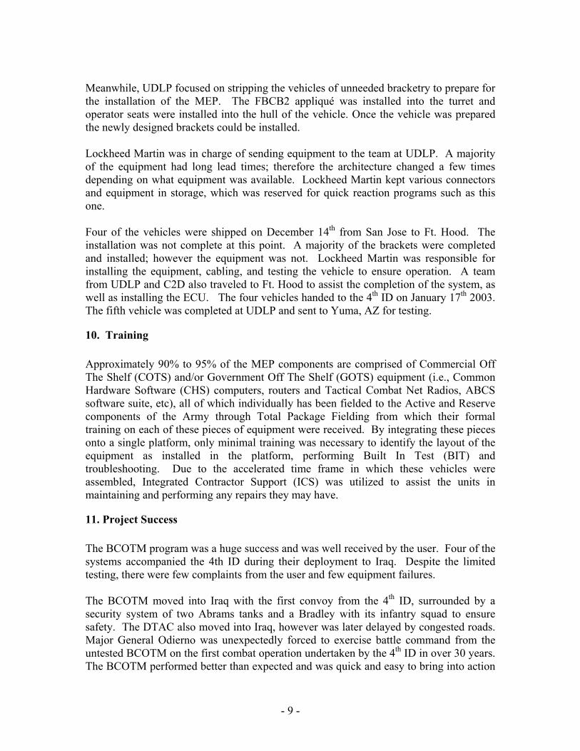
Figure 3: Conceptual Layout of Curbside
9. Development The BCOTM was a rapid response program; therefore typical project management did not apply. PM Platforms brought C2D into the program due to their Quick Reaction Capability (QRC), proved through their rapid prototype efforts on the BCV and the PANDUR. C2D, UDLP, and Lockheed Martin are aware of the constant changing environment, the changing force structure, the threat of war, and numerous other factors that cause the need for a rapid response, and were therefore were prepared to handle the situation. In circumstances such as these, the design, drafting, fabrication, and integration were all worked concurrently to complete the rapid prototyping within the demanding schedule. Once a drawing was complete, it was immediately sent for fabrication. This method allows for quick reaction time, however is not ideal for design situations. Errors are more probable; therefore parts have to be modified during installation. All persons on the program worked 12-hour days, 7 days a week in order to complete the 5 systems within the mission-critical deadline. First, the engineers and designers defined a concept. The mechanical and electrical design could not begin until this concept was finalized. Following the concept definition, C2D started their design of the mounting bracketry, performed analysis on the MPU and rack structures, and started cable design. UDLP began designing the ECU. They built the ECU components into a large, modified bustle box at the curbside rear of the vehicle, with a duct routed to blow cool air directly at the MPU. UDLP also designed mounts for the displays that could be swung aside for ingress and egress.
PRC – 117
UPS
KVM
TCIM
CISCO ROUTER
MPU
MCS-NCU LAPTOP (Stowed)
PRC – 117
UPS
KVM
TCIM
CISCO ROUTER
MPU
MCS-NCU LAPTOP (Stowed)
- 9 -
Meanwhile, UDLP focused on stripping the vehicles of unneeded bracketry to prepare for the installation of the MEP. The FBCB2 appliqué was installed into the turret and operator seats were installed into the hull of the vehicle. Once the vehicle was prepared the newly designed brackets could be installed. Lockheed Martin was in charge of sending equipment to the team at UDLP. A majority of the equipment had long lead times; therefore the architecture changed a few times depending on what equipment was available. Lockheed Martin kept various connectors and equipment in storage, which was reserved for quick reaction programs such as this one. Four of the vehicles were shipped on December 14th from San Jose to Ft. Hood. The installation was not complete at this point. A majority of the brackets were completed and installed; however the equipment was not. Lockheed Martin was responsible for installing the equipment, cabling, and testing the vehicle to ensure operation. A team from UDLP and C2D also traveled to Ft. Hood to assist the completion of the system, as well as installing the ECU. The four vehicles handed to the 4th ID on January 17th 2003. The fifth vehicle was completed at UDLP and sent to Yuma, AZ for testing.
10. Training Approximately 90% to 95% of the MEP components are comprised of Commercial Off The Shelf (COTS) and/or Government Off The Shelf (GOTS) equipment (i.e., Common Hardware Software (CHS) computers, routers and Tactical Combat Net Radios, ABCS software suite, etc), all of which individually has been fielded to the Active and Reserve components of the Army through Total Package Fielding from which their formal training on each of these pieces of equipment were received. By integrating these pieces onto a single platform, only minimal training was necessary to identify the layout of the equipment as installed in the platform, performing Built In Test (BIT) and troubleshooting. Due to the accelerated time frame in which these vehicles were assembled, Integrated Contractor Support (ICS) was utilized to assist the units in maintaining and performing any repairs they may have.
11. Project Success The BCOTM program was a huge success and was well received by the user. Four of the systems accompanied the 4th ID during their deployment to Iraq. Despite the limited testing, there were few complaints from the user and few equipment failures. The BCOTM moved into Iraq with the first convoy from the 4th ID, surrounded by a security system of two Abrams tanks and a Bradley with its infantry squad to ensure safety. The DTAC also moved into Iraq, however was later delayed by congested roads. Major General Odierno was unexpectedly forced to exercise battle command from the untested BCOTM on the first combat operation undertaken by the 4th ID in over 30 years. The BCOTM performed better than expected and was quick and easy to bring into action
- 10 -
to exercise effective operational control, giving MG Odierno a decisive advantage during the 4th ID’s engagements in Iraq. Without its presence the battle would have been delayed by about 9 hours. The four BCOTM systems remain in Iraq to assist with the on going mission.1
12. Lessons Learned As mentioned in section 11, the BCOTM was enormously successful, with few complaints. One remark by the soldiers was the vibration of the displays. Due to the short delivery time, the engineers did not have time to find the optimal design for the system. During the next build the engineers will redesign the brackets and add addition support to minimize the vibration. There were also complaints with the ECU. The belts in the ECU kept breaking, therefore the soldiers had to replace the belt while in the field. The ECU also blew dirt into the MPU, which could cause complications. The engineers will explore other options for the ECU in the next system, possibly cooling the entire vehicle instead of just blowing cool air onto the one piece of hardware. The MSRT and DSVT were removed and replaced with an IRIDIUM cell phone, which is a satellite phone that takes a lot less space claim. The program manager decided that the International Marine/Maritime Satellite (INMARSAT) is an important satellite system that is missing from the BCOTM. The INMARSAT provides non-line-of-sight communication for both voice and data and provides “communications capabilities with maritime, government and civil agencies.”5 A team from UDLP will install the hardware in the space created by removing the MSRT and DSVT once the four vehicles return from Iraq.
13. Future Possibilities The success of this program has led to advancement in battle command on the move, becoming the Mounted Battle Command on the Move (MBCOTM) program. The MBCOTM February 25, 2004 ORD introduces additional capabilities and improvements into the system, such as Blue Force Tracking (BFT). BFT is an improvement to FBCB2. FBCB2 utilizes the tactical internet through line-of-sight FM communications. This system works well on flat terrain, however terrain such as mountains limits the capabilities. The BFT communicates over commercial satellites using transceivers bolted to the top of the vehicles and utilizes the satellite ground station to communicate with each FBCB2 equipped vehicle. The ORD also introduces a dismount radio that can be stowed in the vehicle until needed, as well as including INMARSAT in the architecture. The architecture will be updated as new technology is introduced, and will be modified to include Secure Wireless Lan (SWLAN) and an Unmanned Aerial Vehicle (UAV) feed. The ORD states that the antennas must be removable for transport and that stationary antennas must have provisions to ensure proper grounding, however engineers are
- 11 -
working towards greater advancement in antennas. Multi-band antennas are being developed to reduce the number mounted on a vehicle to mitigate the cosite interference and mounting issues. The engineers hope this technology evolves shortly to utilize it for the program. The army is headed towards using light-armor vehicles for all future MBCOTM systems, which led to the Stryker and up-armored HMMWV as the next platforms used. C2D worked in conjunction with the RDECOM – Tank and Automotive Research, Development and Engineering Center (TARDEC) to design the mounting provisions for the integration of the Mission Equipment Package (MEP) into the Stryker. The design was sent from C2D to TARDEC and was fabricated and installed at their facilities in Detroit. The MBCOTM HMMWV was built solely by C2D in a mock up-armored vehicle. The up-armor HMMWVs are a sought after item in Iraq therefore the MEP was integrated into a standard M1025 HMMWV at C2D’s facilities in Ft. Monmouth, which can later be adapted to an up-armored vehicle. The C2V, the Stryker and HMMWV variants joined the 5th Bradley and all four were showcased at the AUSA winter symposium in Ft. Lauderdale, FL in March 2004.
1. Odierno, Major General Raymond T. and Lieutenant Colonel Edward J. Erickson. “The Battle of Taji and Battle Command on the Move.” Military Review July-August 2003: 2 – 8.
2. C2OTM briefing, May 17, 2001 3. Dunn, Richard J. “Blue Force Tracking, The Afghanistan and Iraq Experience and
Its Implications for the U.S. Army.” Northrop Grumman Mission Systems, Retrieved, March 12, 2004, from http://www.capitol.northgrum.com/files/BFT-WP%20Halfc.pdf
4. Maneuver Control System (MCS). (n.d.). Retrieved March 12, 2004, from http://www.defensedaily.com/progprof/army/mcs.pdf
5. Operational Requirements Document for Mounted Battle Command on the Move ACAT III, February 5, 2004
6. AAMDC Equipment. (n.d.). Retrieved March 12, 2004, from http://www.fas.org/spp/starwars/docops/fm44-94fd/appa.htm
7. Advanced Field Artillery Tactical Data System (AFATDS). (n.d.). Retrieved March 12, 2004, from http://www.globalsecurity.org/military/systems/ground/afatds.htm
8. Army All Source Analysis System. (n.d.). Retrieved March 12, 2004, from http://www.tcs-sec.com/customers/asas/asas.html
9. Battle Command Vehicle (BCV). (n.d.). Retrieved March 13, 2004, from http://www.fas.org/man/dod-101/sys/land/c2v.htm
10. Field Manual 71-100-2. “Infantry Divisions Operations, Tactics, Techniques and Procedures.” August 31, 1993: chapter 2
11. Force XXI Battle Command, Brigade-and-Below (FBCB2). (n.d.). Retrieved March 12, 2004, from http://www.fas.org/man/dod-101/sys/land/fbcb2.htm

- 12 -
12. M4 Command and Control Vehicle (C2V). (n.d.). Retrieved March 13, 2004, from http://www.fas.org/man/dod-101/sys/land/c2v.htm
13. Morris, CPT Kenneth. “Battle Command on-the-move: information as a decisive element in combat power and how we’re working to achieve this.” Army Communicator 21 (spring 2002): 26-29.