baxi luna 310 fi technical information · water temperature at the tap will depend on three...
TRANSCRIPT
BAXI LUNA 310 Fi
TECHNICAL INFORMATION

Baxi Luna Wall-Hung Boiler
Commissioning Checklist
Please attend to each of these items before calling for technical assistance
Venting connected and secure
Power supply properly polarized
Relay in place and properly wired to thermostat
All isolation valves are open
Air has been purged from heating system
No visible water leaks (drip stains)
Pressure gauge stable at 1.5mbar
Gas pressure settings are correct
Hot system flush performed
User manual left on site
It is very important that these steps be carried out in order to have the boiler operate without any additional service required.
Baxi N.A.PO Box 4729
Utica, NY 13504 Tel. 1 844 422 9462Fax. 1 866 432 7329
www.baxiboilers.com

Baxi Luna 310fi Features & Benefits
Gas-fired wall hung combination boilerInput from 126,000 BTUH to 45,000 BTUHOutput from 105,000 BTUH to 35,000 BTUHAutomatically modulates output to meet demand“On Demand” domestic hot water with no storage tankPrioritizes to domestic hot water & does not mix heating water with domestic hotwaterDirect vent, sealed combustionComes complete with 4” concentric vent termination, 90-degree vent elbow & valvekit (pre-swedged to accept ¾” & ½” copper pipe)Reduces mechanical room from 100 sq.ft. to 6 sq. ft. --saving valuable floor spaceCan be mounted in closets or between kitchen cabinetsVirtually silent operationUser friendly control panel, featuring individual heating & DHW controlsEasy service access from front of unit and diagnostic LED’s for easy trouble shootingBuilt-in circulation pumpBuilt-in relief valveBuilt-in pump timer (circulates pump for 5 minutes every 24 hours if system has notoperated)Built-in automatic air ventBuilt-in expansion tankBuilt-in backflow preventerBuilt-in Hi-Limit, frost protection, low water cut-out controlsBuilt-in pressure gauge10-year warranty on heat exchangers; extended parts and labour warranties availableOutdoor reset control optionAttractive leasing programs available
Baxi N.A.PO Box 4729
Utica, NY 13504 Tel. 1 844 422 9462Fax. 1 866 432 7329
www.baxiboilers.com

With the boiler in place on the wall, measure the distance from the face of the flue elbow to the outside of the wall (X) fig.3. Transfer this measurement onto the outside air duct. Take this measurement from a spot about ½ inch back from the terminal fixing screw. Do this so that if you ever need to remove the termination cap you can access the screws. Mark around the duct and cut off the excess duct. Transfer the measurement of the waste piece of duct onto the smaller flue duct fig.4 and cut this off. Make sure that the flue duct is not cut short, as this will cause problems
Standard venting
Duct can be cut with a hacksaw

Coaxial venting
The coaxial (concentric) venting has a maximum operating length of 4mtr. (13.2 ft) in either the horizontal or vertical configuration. The
elbow supplied with the standard horizontal flue is not included in any equivalent length calculations. Any additional “in line” bends in the
flue must be taken into consideration. A 45° bend = 0.5 mtr (19.5”). A 90° bend = 1.0 mtr. (39.5”)
The illustrations above show examples of maximum equivalent vent lengths. Note in the vertical configuration the vent is measured from the top of the boiler to the underside of the vertical termination fitting.
Coaxial venting is classed as ‘0’ clearance to combustibles.

Vent restrictor and clamps
The boiler is supplied with a vent restrictor ring (fig.5) fitted in the flue connection. This is needed if the vent length is less than 1.5 mtr. (5ft). For venting lengths more than 1.5 m., remove and discard.
The venting is joined together with clamps. These clamps are supplied with each piece of vent ducting or fitting. The inner flue duct uses a metal clamp. This clamp is used as is, no sealant is required. The outer air duct is used with the silicone gasket seal. This gasket allows the air duct to be fitted with a gap between the air ducts if in a tight spot; the gap allows the inner clamp to be tightened before the outer clamp is tightened.

Two pipe venting
For venting lengths greater than 4 mtr. (13.2 ft) two separate air ducts are required
The maximum vent length for two pipe venting in the horizontal configuration is 8 m. (26.3 ft). Any “in line” bends must be taken
into consideration for the equivalent vent length calculation. A 45° bend = 0.25 m (10”). A 90° bend = 0.5 m (19.5”).
IMPORTANT: ensure a minimum downward slope of 1 cm per each metre of duct length toward the outside (1/4” per each 3ft).
The maximum vent length for two pipe venting in the vertical configuration is 12 m. (39.3ft). Any “in line” bends must be taken into consideration for equivalent vent length calculation.
A 45° bend = 0.25 m. (10”). A 90° bend = 0.5 m. (19.5”). IMPORTANT: if the flue duct exceeds 6 mtrs the condensate collector
kit (supplied as an accessory) must be fitted close to the boiler.
2 pipe venting will have to have the flue vent pipe insulated from combustible materials

Luna 310 control panel
The control panel selector switch (#1) has three positions: center is the off position; to the right is hot water mode only, and to the left is the heating and hot water mode. If the switch is turned fully to the left, this will reset the controls if a fault light is flashing. The reset is spring operated and will return to the normal position.
The heating thermostat control (#2) will control the heating closed loop temperature with the T.RISC. in the off position from 30°C (85°F) to 85°C (180°F). With the T.RISC. in the on position the heating closed loop temperature will operate from 30°C (85°F) to 45° (110°F).
The domestic hot water thermostat (#3) will control the temperature of the hot water to a maximum of 65°C (149°F). The domestic hot water temperature at the tap will depend on three factors,
1. The set position of the thermostat knob.2. The temperature of the cold water entering the boiler.3. The flow rate of hot water leaving the boiler.
The minimum flow of hot water needed to bring the boiler on is 2.5 l/m (0.5 gpm). The maximum flow is controlled by the flow regulator to 12.7 l/m (2.8 gpm. Imperial, 3.3 gpm US).

Boiler LED display
The control panel pressure gauge #4 shows the pressure of the closed loop heating system. The system pressure must be between 1Bar and 1.5 Bar (15 psi and 21 psi). If the pressure falls below 0.5 Bar (7.5 PSI), the low water cut off will operate and the boiler will not fire. If the water pressure in the closed loop has to be continually topped up, there is a leak in the system, which must be found and repaired. The other symbols and LED lights on the control panel are for the closed loop temperature display and for troubleshooting. The red LED’s numbers 6-11 have a duel function, they will light up in progression to show the temperature of the closed loop and remain constantly illuminated. If a fault develops, the appropriate LED will begin to flash. LED 12 will be on all of the time the boiler is turned on. LED 13 or 14 will light up when there is a call for Hot water (13) or Heating (14), there will only ever be one or the other of these LED’s on, never both at the same time. LED 15 will light and stay on to show that the burner is alight and operating.
The flashing LED’s will indicate the following faults: • 6. Flame failure• 7. High Limit thermostat operated• 8. Fault with the Fan, Air pressure switch or the Venting• 9. Fault with the Pump or Low system pressure• 10. Faulty Hot Water Sensor• 11. Faulty Heating Sensor

Electrical and room thermostat
Line 120V To gain access to the
control PCB, undo the screws that keep the
control panel in place and lower the control panel.
On the back left side of the control panel is the PCB cover. Remove the two
screws holding this cover in place, push the retaining clips and lift the cover up and toward you. If you are just checking the 3.15amp fuse do not remove the full cover, just ‘pop’ the access
panel on the left.
To connect an external control to the boiler,
remove yellow link wire between terminals 1 and 2
and connect the cables here
IMPORTANT: The external control MUST be suitable for 120V switching. The
output from terminal 1and2 is 120V
The BAXI LUNA 3.10 is supplied with a 1-meter
cord, ready to plug into a nearby power outlet. This boiler is polarity
sensitive, before commissioning the boiler electrical system checks
should be done. These should be performed with a suitable meter, and include checks for Ground Continuity, Resistance to Ground, Short Circuit and
Polarity.

Electronic PCB jumper settings
On the electronic PCB, you will find four jumpers, which allow you to make some changes to the operation of the boiler. These jumpers have two pins; with the jumper fixed on the two pins (Fig.30), the switch is ‘on’, with the jumper on the left pin only (Fig.29), the switch is ‘off’. When you unpack the boiler from the shipping carton, you will find that the only jumper in the ‘on’ position is the T-off jumper. This will allow the burner to re-light after a 10 second delay, when operating in the heating mode; we recommend this be moved to the ‘off’ position. This will allow the burner to stay off for 3 minutes, once the boiler thermostat has turned it off. This will stop the boiler from ‘short cycling’ and creating low temperatures in the vent during cold weather, thus preventing the vent from icing up. The T.RISC. jumper in the ‘off’ position allows the boiler to operate from 30°C - 85°C (85°F - 180°F). In the ‘on’ position, it will operate from 30°C - 45°C (85°F - 110°F). This is for systems requiring low temperatures such as radiant floor systems. The GPL jumper will be set by the factory for natural gas or propane. The POMPA jumper in the ‘off’ position starts and stops the boiler pump when the boiler operates. In the ‘on’ position the boiler pump will run continuously when the heating operation is selected.
Turn off the power when changing jumper positions

Gas Valve and how to set the gas pressures
The gas valve has a working inlet pressure of 7”w.c. for natural gas, and 11”w.c. for LP gas. There is a pressure drop through the valve of approximately 1”w.c. As the maximum operating gas pressure for natural gas is 5.6”w.c. and 9.8”w.c. for LP gas, it is important to test the gas pressure at the inlet test point with the hot water running.
The gas valve on the LUNA boiler is a fully electronic modulating gas valve. That is to say, it will automatically adjust the operating gas pressure to meet the demand on the boiler at that time. When there is a high demand, the gas pressure will go up to high fire to satisfy that need. As the temperature of the water in the boiler increases, the gas pressure will automatically reduce to save energy. With conventional firing boilers or furnaces, the appliance is either on or off, firing at the preset heat output of that particular unit. If it is say, a 75,000 BTU furnace, it will fire at 75,000 BTUs until either the appliance thermostat or the room thermostat is satisfied, and then shut off, then fire up at 75,000 BTUs again and so on until the end of the heat cycle. With modulation, the boiler will start at 75,000 BTUs, but will recognize that as the system starts to heat it no longer need the same 75,000 BTUs to do the same job, and will start to fire at 70,000 BTUs then 65,000 and then 60,000 and so on until either of the thermostats are satisfied. The boiler will modulate in both the heating and the domestic hot water mode. When operating in the domestic hot water mode, the burner must stay alight to avoid fluctuating hot water from the hot tap, therefore, you must check the high and low gas pressures.

Checking and setting the high and low gas pressure
Contrary to popular belief, most gas appliances are not factory set. Even if they say they are factory tested, an on-site check will invariably
reveal varying degrees of accuracy. With this in mind, after installing the boiler we strongly recommend that you set up the gas pressure. There are two gas pressures to set,
high fire and low fire. Once these are checked and adjusted if necessary, the boiler will then modulate automatically between high
and low fire. Set the high fire before the low fire setting.
To set the high fire, open an unrestricted hot tap, the boiler will fire up and go up to high
fire. The high fire gas pressure must be 5.6”w.c.
If this is not correct, you will need to adjust the gas valve in
the following manner. With a 10mm wrench on the gas valve modulating pin (see foto 1); turn the nut clockwise to increase the gas pressure, or turn it counter clockwise to
reduce the gas pressure. If the boiler starts to modulate down
before you have set the gas pressure, remove one wire from the solenoid coil for a short time
to cool the boiler.
The low fire gas pressure can only be set once the high fire setting is correct. The low fire gas pressure
must be 0.7”w.c. After you have checked the high fire, and with the hot tap still running remove one of the wires from the solenoid coil (see foto 2); the burner will drop to low fire. If the low fire gas pressure is not correct, it can be adjusted by turning the red philips screw in the center of the modulating pin (see foto 2). Turn the red screw clockwise to increase the gas pressure, or turning counter clockwise will reduce the gas pressure. Reattach the solenoid wire.
Diverter valve assembly
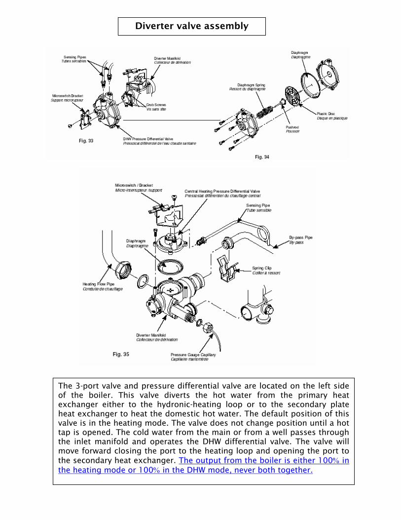
The 3-port valve and pressure differential valve are located on the left side of the boiler. This valve diverts the hot water from the primary heat exchanger either to the hydronic-heating loop or to the secondary plate heat exchanger to heat the domestic hot water. The default position of this valve is in the heating mode. The valve does not change position until a hot tap is opened. The cold water from the main or from a well passes through the inlet manifold and operates the DHW differential valve. The valve will move forward closing the port to the heating loop and opening the port to the secondary heat exchanger. The output from the boiler is either 100% in the heating mode or 100% in the DHW mode, never both together.

DHW venturi and flow regulator
Position of the flow
regulator and venturi
Fig.36 shows the flow regulator and venturi assembly. The venturi makes the DHW pressure differential valve operate. Water flowing through the inlet manifold passes quicker through the venturi; this lowers the pressure on the front of the DHW diaphragm and increases the pressure on the back. This allows the diaphragm to move forward, which in turn allows the 3-port valve to move forward closing the heating port and opening the DHW port. To remove this assembly, close the cold-water inlet valve under the boiler and open a hot tap to relive the pressure in the plumbing pipe work. Fig.18 shows the position of the assembly under the pump. The assembly can be removed by un-screwing counterclockwise and lifting out. Check the filter, flow regulator and venturi for debris, rinsing in clean water as necessary.
Reassemble in reverse order.

NTC (Negative Temperature Coefficient) sensors, also known as thermistors. There are two sensors in the LUNA 3.10 Fi boiler. The primary flow sensor is located in a dry well, on the outlet pipe from the main heat exchanger. The DHW sensor is located in the outlet manifold of the secondary heat exchanger, this is in the waterway. Both sensors are the same part number. A thermistor is a heat sensitive resistor, and should show a resistance if electrically tested. Although any given resistance is directly proportional to a corresponding temperature, measurement of resistance at a specific temperature is usually beyond the scope of the installer. If the primary sensor is replaced, a suitable thermal grease must be used, failure to do so will result in ineffective temperature sensing. One fault with an NTC sensor is that it could go ‘open circuit’ at high temperature.

Grundfos Pump
The pump moves the water in the boiler and the heating system through the primary heat exchanger, and when in the DHW mode through the secondary heat exchanger also. Whatever is in the heating system pipe work and equipment will pass through the pump. If the installation, be it new or old has not been flushed correctly the debris, oil and flux in the system will damage the rotor and barings in the pump. We recommend that the system be flushed before opening the shut off valves to the boiler; this will prevent debris from being pushed through the boiler. Then run the boiler to maximum temperature, drain and flush again. This will remove any oil and flux remaining in the system.
The pump used in the Luna 3.10 Fi boiler is the Grundfos UPS high head series. This pump has been specially designed by Grundfos for BAXI. The pump body incorporates an automatic air bleeder for venting the air from the boiler. If the boiler is the highest point in the heating system, the air will vent through the AAV. If you have pipe work or equipment above the boiler this AAV will not vent all of the air from the system, a suitable vent must be fitted at the highest point in the system. Available pump head for the heating system see the graph below.

Luna 310 & 1.31 Flushing Procedure
The procedure for flushing the closed loop is as follows:
• Connect a hose to the system drain tap• Close the boiler heating supply valve (this will allow clean water to be flushedthrough the boiler first)• Open the drain tap on the closed loop• Open the fill valve on the boiler (the blue handle under the boiler)]• When you see clear water coming from the hose, close the fill valve• Now open the boiler heating supply valve and close the return valve• Open the fill valve on the boiler (this will flush the rest of the system)• When you see clear water coming from the hose, close the fill valve• Close the drain tap and remove the hose• Pressurize the system to the correct pressure on the pressure gauge

BAXI LUNA 310 Fi Troubleshooting Guide Before getting started, remember…
Most of the faults experienced on start up are field issues associated with items external to the boiler. These are mostly simple problems, such as:
• Venting installed incorrectly• Air in the system (system must be fully purged)• Air in the gas line• Undersized gas line• System not flushed (cold flush then hot flush)• Incorrect connection of external equipment• Leaks in the Heating system and pipe-work
All BAXI LUNA boilers are tested during manufacture for correct operation and are shipped to you factory tested for correct operation. Notwithstanding, while commissioning the boiler, a few items need to be checked:
• Inlet gas pressure (static and working inlet pressure of boiler running atmaximum output)
• Maximum and minimum burner pressures• Power supply for polarity and ground
When troubleshooting BAXI LUNA boilers, avoid changing parts prematurely do not jump to the conclusion that a boiler component is defective. For example:
• Parts such as the control PCB are changed incorrectly, when it is anothercomponent supplying false information to it.
• The pump is sometimes changed unnecessarily because it has stoppedoperating. A pump operational fault is normally the result of contaminationfrom a dirty hydronic system – in which case, the pump can be removed andcleaned (after which the heating system must be flushed and cleaned), and thenreturned to normal operation.
Get all the information before going to the job site……………
Get as much information from your customer before you go to the boiler: model of boiler; type of venting; type of system and layout connected to the boiler; how long has the system been installed, and is this an isolated breakdown or are they repeatedly resetting the boiler? Don’t be afraid to ask the obvious questions! Does your customer know how to reset the boiler? (Just unplugging the lead and replacing it, or turning the boiler off and on again will not reset the logic board.) They have to turn the switch to “R” to restart the boiler. Is there any water in the system? Where is the needle on the pressure gauge? This may save an unnecessary trip to the job site.

BAXI LUNA 310 Fi troubleshooting guide
Fault Cause Suggested SolutionsBoiler does not start No power at the Check 120 Vac at power cord outlet.no LED's lit. boiler Check if main 3.15 amp boiler fuse has blown.
Boiler does not start #14 LED not lit No signal from external control. Remove wires from thermostat connectionsbut #12 LED is lit. (call for heat) 1&2 at terminal strip and jumper it. If boiler starts replace switching relay.
Boiler does not start #13 LED not lit Open DHW tap fully, has pin moved out from DHW differential assembly tobut #12 LED is lit. (call for DHW) close micro switch (green wires)? No; DHW flow valve diaphragm damaged
replace. If diaphragm OK clean and lubricate DHW valve rod. Yes; check
continuity across DHW micro switch, replace if faulty.
Boiler does not start Low water pressure Re-pressurize heating system till pressure gauge reads between 1-2 Barbut #12 and #13 or on gauge. Check for and repair leaks in heating system.#14 LED's are lit.
Primary/DHW sensor Check DHW/ Primary temperature sensors for cold resistance of approxfaulty. 11 K Ω (resistance reduces with increase in temp), replace if faulty.
Pump not operating Check for 120 V at pump, if no power and sensors OK, replace main PCB. 120 V at pump, but pump not turning. Release jammed pump by removingvent cap on front of pump and turning shaft counter-clockwise. If pump will notturn. Drain boiler, remove pump head release and clean pump cartridge.
Air in system If pump is running but the flow switch has not closed, or is "bouncing" upand down, purge air from the pump and heating system.
Flow switch faulty If pump is running but flow switch has not closed; has pin moved out fromdiverter valve to close micro switch? No; flow switch diaphragm damaged,replace. If diaphragm Ok clean and lubricate flow switch rod. Yes; check
continuity across primary flow micro switch, replace if faulty.
Pump running, flow Air switch not Check air switch has not stuck in the open position. To check, remove roomswitch closed fan operating sealed door on boiler and pull suction tube from fan venturi. Gently suck onnot running the end of the sensing tube, you should hear the air switch operating. Re-
connect the sensing tube and retry lighting boiler, (signal from PCB to fan onstart is via the NC terminals on the air switch). If air switch OK replace PCB.

BAXI LUNA 310 Fi troubleshooting guide
Fault Cause Suggested SolutionsFan running, #8 (50°) Air switch notfault code flashing. operating?
Moisture in air This may be due to excess vent outside of building. Trim vent back to wall.switch suction tube. Insulate vent in unconditioned spaces.
Dirt in fan venturi. Remove fan transition bend and inspect for debris.
Scale at venturi port Remove fan transition bend and inspect for scale and deposits. Clear venturiport with #32 index drill. If this does not cure problem replace fan venturi.Note: scaling is probably due to vent sloping toward the boiler, ensure that
vent is sloping toward the terminal.
Severe local wind Check position of terminal, avoid terminating where other buildings and plantingsconditions. will affect boiler flue operation.
Incorrect vent length Check for incorrect vent installation or excess vent length.or configuration. If all of the above are OK replace air switch.
Boiler does not light No spark at burner. Check for 120 V at the spark generator. If voltage at spark generator, replace#6 (30°) fault code spark generator. No voltage at spark generator, replace main PCB.flashing.
No gas pressure at Check gas supply to boiler, is gas shut off valve open?gas valve burner test Check gas valve main solenoids with power turned off. Approx 175 Ω coldport. resistance on both main coils. If low or open, change gas valve.
Check inlet screen for blockage on inlet side of the gas valve.
Boiler lights then goes No ground to boiler. Check for good ground at outlet and at boiler.out, #6 (30°) fault code flashing. Flame lifting off burner Exhaust venting has come apart, check installation. If long horizontal run of vent
or 'ghosting'. suggest using support spacers, available as an accessory. Exhaust vent does not extend to the end of the terminal, rectify fault. Air supply to boiler insufficient, check for blockage and correct vent installation. Air in gas line.
Week or no signal Check for minimum 1 mA flame currant from flame sensing electrode. No; cleanfrom flame sensor. or replace electrode. Yes; replace main PCB.
Boiler will not Minimum gas pressure Remove black wire from modulating coil while boiler operating, check low firemodulate. to high. gas setting. Reset if required.
Remove modulating pin and inspect. Check that when end is pulled it springsback into place. If broken replace (this is usually broken when inlet gas pressureis low, to much adjustment has been made on pin to try to get boiler to high fire). Check voltage across modulating coil when operating, approx 10 Vdc high fire1.5 Vdc low fire. Cold resistance on modulating coil approx 40Ω (with power off), if low or open
replace coil.

BAXI LUNA 310 Fi troubleshooting guide
Fault Cause Suggested SolutionsBoiler short cycling. Heating output has not Set the "Max R" on the control PCB to match the heating system requirements,
been set. see chart on page 25 in manual for settings.
Short cycling on a In a smaller system make sure the T-Off Jumper on the PCB is set to the left,short heating circuit. this will give a 3 min. delay when the burner turns off in the heating mode.
If zone valves are present in system, the internal bypass is not designed tohandle system flow, it is only used for boiler pump protection. Install a separatepressure-activated bypass, a buffer tank or a low loss header.
Whistling noise from High fire when using BAXI recommends that only 25% inhibited propylene glycol solutionsboiler. Glycol in system. (specially formulated for hydronic systems) be used in the LUNA boiler. Ethylene
glycol is toxic and can attack gaskets and seals used in hydronic systems.Check that the glycol ratio is not more than the recommended amount yearly,a higher ratio can affect the pump performance causing noise at high fire.Note: Anti-freeze solutions expand more than water -- e.g., 50% by volumesolution expands 4.8% in volume for a temperature increase from 32°F to 180°F,while water expands 3% with the same temperature rise. Allowances must bemade for this expansion in the system design. A 30% mixture of glycol will resultin a BTU output loss of 15% with a 5% increase in head against the boiler pump.A 50% mixture of glycol will result in a BTU output loss of 30%, with a 50%increase in head against the boiler pump.
Fluctuating DHW Boiler cycles on/off Check that low fire is not set to high. Reset if required.temperature at tap.
Erratic burner Check burner pressure at gas valve test port with manometer while boilerpressure. operating. If gas pressure fluctuates erratically suspect either primary sensor is
out of calibration or the DHW sensor is dirty. Replace one or both sensors.
Burner pressure Check burner pressure at gas valve test port with manometer while boilerfluctuates from high operating. If gas pressure fluctuates from high to low then back to high suspectto low fire. that the DHW plate exchanger is dirty or scaled up. Remove and clean/ de-scale
with suitable cleaner, or replace heat exchanger. If the boiler is being used with a well, make sure the supply pressure is good.If the pump setting is set for 40 Psi-on/60 Psi-off, try 50 Psi-on/70 Psi-off.
Fluctuating If previous checks are OK check the temperature of the hot water at a singletemperature at tap (not single lever tap). If the temperature is stable (within 3-5°f) at this tapshower. suspect that the shower valve cartridge is dirty or faulty, clean or replace cartridge.
Note: taps that have internal plastic parts tend to cause fluctuations in water flow.
Plastic has a faster expansion rate than brass as the water heats it up it tends toexpand and slow the water flow. The tap then needs to be opened further to let thewater flow faster, which in turn increases the water flow through the boiler.
Hot water not hot Incorrect gas Check that the boiler has the correct maximum gas pressure.enough. pressure.
Faulty/Dirty NTC Check that the DHW sensor is not dirty or scaled up. Check that sensor is notsensor. out of calibration (10 K Ω @ 25°C). Replace if faulty.
If PCB has been changed has the boiler thermostat knob been fitted correctly?

BAXI LUNA 310 Fi troubleshooting guide
Ω
Fault Cause Suggested SolutionsCold water mixing Check that the flow from the hot tap is not more than 3.3 GPM (18 secondswith hot to taps. to fill a 1 gallon bucket). If bucket fills faster the tap is mixing with cold water.Water temperature During the winter months the cold water temperature entering the boiler can bein the winter. 10°f lower than in the summer, this will reduce the hot water by 10°f at full flow.
No water pressure Flow restrictor in There is not a problem with the hot water pressure. It is essential toat bath tap. boiler. educate the user how the boiler uses the flow regulator to get the correct temperature
rise at full flow. Bath taps are normally 3/4" and in some cases with a 3/4" supplypipe. With a restrictor fitted to the boiler it may appear as if there is a problem withthe flow rate.
Little or no hot water Hot and cold pipes Suspect the installer has connected the hot outlet pipe to the inlet valve. To checkat tap. crossed at boiler. operate the heating in order to warm up the domestic hot water heat exchanger.
Open hot tap; if incorrectly installed, the right hand 1/2" pipe, which should remain coldwill become warm.
Dirt in the 3 port Diverter valve does not fully closein the DHW mode. To check, with heating
diverter valve. cold or cool, run the hot water and feel the heating supply pipe approx 2-3 feetfrom the boiler. If the pipe gets hot this indicates that the 3 port valve is not closingfully. Strip diverter valve, clean and lubricate, or replace.
Boiler slow to start Dirt in DHW venturi. If the hot tap needs to be fully opened before the boiler fires, there is dirt in thein DHW mode. venturi. Strip down and clean the water pressure sensor (venturi).Boiler has been Dirty DHW heat This can be especially true when the boiler has been installed on an existingoperating for some exchanger. system. Suspect contamination from older parts of system. Surfaces of DHW heattime with no problems exchanger has been coated, not allowing heat transfer to take place from the primaryuntil hot/cold problem water, with the result that the boiler shuts down on its safety thermostat.ie: with shower If in a hard water area, suspect the potable side of the heat exchanger is scaled upbecomes apparent. causing the same problem. De-scale or replace DHW heat exchanger.
#6 (30°f) fault code. Flame failure. Check gas supply, flame signal or ground to boiler.
#7 (40°f) fault code. Safety thermostat Check continuity across thermostat terminals, when cool more than 1 resistance.activated. Check for scaling or contamination in primary heat exchanger.
#8 (50°f) fault code. Fault on fan or flue. Check venting, fan venturi, air switch sensing tubes and air switch.
#9 (60°f) fault code. Fault on pump or low Check low system pressure, air in system, jammed or faulty pump.system pressure.
#10 (70°f) fault code. Fault on DHW sensor. Check DHW sensor for correct resistance reading or is open circuit.
#11 (80°f) fault code. Fault on primary Check primary sensor for correct resistance reading or is open circuit.sensor.
Note: in some instances the #6 (30°f) fault will flash as well as another fault code
light. This is because the boiler will show this fault code if the boiler has not detecteda flame after 10 seconds on start up.