bbr big bore 88cc ftp installation instructions€¦ · · 2017-03-12crf/xr50 bbr big bore 88cc...
TRANSCRIPT
M O
T O
R S
P O
R T
S
BB
R B
IG B
OR
E 8
8CC
FTP
INS
TALL
ATI
ON
INS
TRU
CTI
ON
S
CRF/XR50 1
02
8 4
th S
t. SW
- A
, Au
bu
rn, W
A 9
80
01
·
Ph
on
e: (
25
3) 6
31
-82
33
Fa
x: (
25
3) 6
31
-82
33
· w
ww
.bb
rmo
tors
po
rts.
com

Installation of this piston kit is iden ti cal to OEM installation. Please refer to the Honda shop manual or a qualifi ed me chan ic for as sis tance or questions. These instructions are not intended to be a replacement for the Honda shop manual. Read all instructions carefully before installation. Make sure that the mo tor cy cle has cooled down and has been se cured. Clean the motorcycle thoroughly to insure that no dirt or foreign objects can enter the engine.
Every effort has been made to insure the qual i ty of this prod uct. Because BBR cannot con trol the in stal la tion or use there is NO war ran tee or guar an tee with this product. Using quality motorcycle oil will help prolong engine life. Be sure to change it often.Required Tools:
Service Manual8mm socket or wrench9mm socket or wrench10mm socket or wrenchTorque wrenchLarge fl at head screwdriver or small pry bar
Torque Values:8mm nuts/bolts: 9 N-m (0.9 kgf-m, 6.5
lbf-ft)9mm bolts: 10 N-m (1.0 kgf-m, 7 lbf-ft)10mm bolts: 11 N-m (1.1kgf-m, 8 lbf-ft)
BBR Recommends using the stock 58 main jet with the stock carbuerator. Included is a 62 main jet for colder weather or highly
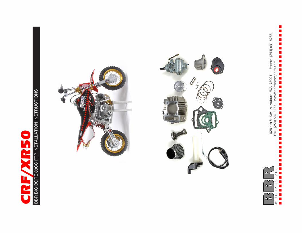
BBR BIG BORE KIT AND HIGH-PERFORMANCE CAMSHAFT INSTALLATION IN STRUC TIONS
CRF/XR50
M O T O R S P O R T S 1028 4th St SW - A, Auburn, WA 98001 · Phone: (253) 631-8233 · Fax: (253) 631-8233 · www.bbrmotorsports.com
1. Valve covers/caps2. Cam sprocket3. Cylinder stud nuts and washers4. Piston assembly5. Cam sprocket cover6. Flywheel cover7. Cylinder
8. Dowels9. Right side head cover10. Camchain roller11. Top head cover12. Head gasket13. Base gasket14. Oil passage O-rings
7
5
8
3
1
9
6
24
11

.4. Remove the 2 large round 17mm valve cover caps. Re- move the four 10mm nuts from the top cylinder head cover and re move the cover (shown at right with caps and cover al- ready removed).
Disassembly in struc tions:The installation can be done with or with out the engine in-stalled in the frame. To re move the engine from the frame remove the 2 large engine mounting bolts, throt tle cable, air fi lter assembly, and chain.
1. Remove the left side cover (fl ywheel cover) from the motor (three 8mm bolts).
2. Remove the left side timing chain/camshaft cover by re- mov ing the 10mm bolt on the right side of the engine (shown with arrow). This bolt extends through the camshaft and se-cures the camshaft cover.
3. Remove the right side cyl- in der head cover by re mov ing the remaining two 8mm bolts.
5. Remove the cam sprock et from inside the left of the cylin-der head by removing its two 8mm bolts.
6. Remove the 10mm cam chain roller bolt from the cyl- in der (shown with the middle arrow). Re move the 2 left side cylinder bolts (10mm with Phillips heads - shown with the outside arrows).
7. Remove the cylinder head, gasket, and 2 alignment dow- els. A well used motor may require some force to get the base gasket to re lease the cylinder. A rubber hammer may be helpful - but be very careful! Do NOT use a screw driver to pry it up, or you will destroy the cases!

8. Remove the cam chain roller from inside the cylinder. Needle nose pliers may be help ful.
9. Remove the cylinder by sliding it up off of the pis ton. Next remove the 2 dowels, gasket, and o-ring.
10. Remove one of the small piston clips from inside the piston (use a small screw-driver or needle-nose pliers). Push out the piston pin, and remove the piston from the shaft.
11.* Cam Removal & In stal -la tion: Loosen the valve ad-justers all the way and the cam may pull out. If i does not, re-move the cam by com press ing the ex haust valve with a large screw driv er or other prying ob-ject and slide the cam out. Next com press the intake valve and con tin ue sliding the cam out of the cyl in der head. Use care not to bend the valves or dam-age the cylinder head.
12. Install the new BBR cam in reverse order making sure that the cam lobes are facing down (in towards the engine). The bare camshaft is pictured at the right. No tice the lobes fac ing down.
13. Piston Ring Installation:Using your fi ngers and a min- i mal amount of force, pry each ring over the pis ton and slide it into the groove. Apply a thin coat of motor oil onto each ring before in stall ing.· Install the oil expander ring (the wavy ring) onto the bot tom groove. See bottom drawing.· Install the two thin rings: one below the oil ex pand er ring and one above, in the same groove.· Install the black ring onto the center groove making sure any letters face up.· Install the black and silver ring onto the top groove mak ing sure any letters face up.· Rotate all gaps in rings ap- prox i mate ly 90 degrees from each other so they do not line up. Also make sure that the oil ex pand er ring does not over lap itself.
*This step is not neccesary if you are installing the stroker kit.

14. Piston Installation: Install one of the provided piston clips onto the piston. Push the piston into the cyl in der mak ing sure that the “IN” is facing the front of the cylinder (towards the top of the engine). Use your fi ngers to compress the rings and slide inside the cyl in der.
17. When installing the top cyl in der head cover make sure the arrow on the cover is point- ing down. Place the copper wash er onto the bottom left bolt. Place the plain nut onto the bottom right bolt.
15. Make sure that the crank is at top dead center (at the top of its stroke or TDC). This is indicatd by the “T” on the fl y wheel lining up with the notch on the case. If it is not, turn the fl ywheel until it is in this position.
16. Slide the cylinder onto the engine after placing the gasket. O-ring, and dowels onto engine cases. Once the piston has reached the con- nect ing rod install the wrist pin through the piston and install the 2nd circlip to secure the piston pin.
18. Cam Sprocket In stal -la tion: When installing the cam sprocket make sure that the “T” on the fl ywheel is still lined up with the mark on the engine case. Make sure the circle on the cam sprock et is lined up with the mark on the cylinder head.
19. When installing the round left side cam sprocket cover make sure that the tab on the cover is lined up with the tab on the case.
Setting the valve clearance:With the piston still at TDC, Loosen the 9mm bolt on the valve adjuster. Using a feeler gauge slide it between the valve and the threaded pin Thread the pin in or out until the feeler gauge fi ts snuggly but slides easily. Retighten the 9mm bolt at this po si tion and in stall the valve cover. Repeat with the other valve.
Valve clearance: Intake: .002 in (.05mm) Exhaust: .003 in (.07mm)
Continue installing any other parts you have not installed yet and reassemble the mo tor cy cle (if you took the motor out of the en- gine). Be sure to check the oil level before running the mo tor cy cle.
CopperWasher
Plain Nut
Arrow
Mark on Head
Mark on Sprocket
ValveAdjuster
Notch
Top Dead Center Mark - “T”