bcp-h2 - bluesens · bcp-h2 operating manual rev. 150805001 3 en 1 about this document 1.1 function...
TRANSCRIPT

Rev.150805001
Operating Manual Multilingual
BCP-H2
Deutsch
English

BCP-H2 OPERATING MANUAL
Rev. 150805001 1
EN

BCP-H2 OPERATING MANUAL
Rev. 150805001 2
EN
Contents
1 ABOUT THIS DOCUMENT ................................................................................................................ 3
1.1 Function ......................................................................................................................................................... 3
1.2 Target group .................................................................................................................................................. 3
1.3 Symbols used ................................................................................................................................................ 3
2 FOR YOUR SAFETY .......................................................................................................................... 4
2.1 General information ....................................................................................................................................... 4
2.2 Authorized personnel .................................................................................................................................... 4
2.3 Proper use ..................................................................................................................................................... 4
2.4 Misuse warning ............................................................................................................................................. 4
2.5 General safety information ............................................................................................................................ 4
2.6 CE conformity ................................................................................................................................................ 5
3 PRODUCT DESCRIPTION ................................................................................................................ 5
3.1 One-piece construction of the BCP-H2 ......................................................................................................... 5
3.2 Measuring principle ....................................................................................................................................... 5
4 INSTALLATION .................................................................................................................................. 6
4.1 General instructions ...................................................................................................................................... 6
4.2 Mechanical connection .................................................................................................................................. 6
4.2.1 Installation on pipes ................................................................................................................................. 7
4.2.2 Installation on a Tri-Clamp SMS38 connection ........................................................................................ 7
4.2.3 Installation on a POM flow adapter .......................................................................................................... 8
4.2.4 Installation on a stainless steel flow adapter ............................................................................................ 8
4.3 Electrical connection ..................................................................................................................................... 9
4.3.1 General information .................................................................................................................................. 9
4.3.2 Version 4 – 20 mA in PA6 housing ........................................................................................................ 10
4.3.3 RS232 serial version in PA6 housing ..................................................................................................... 11
4.3.4 Version 4 – 20 mA in aluminum housing ............................................................................................... 12
4.3.5 RS232 serial version in aluminum housing ............................................................................................ 13
4.3.6 Connection via BACCom12 ................................................................................................................... 14
4.4 Cross-sensitivity to other gases .................................................................................................................. 16
5 MAINTENANCE ............................................................................................................................... 17
5.1 1-point calibration ........................................................................................................................................ 17
5.2 Recalibration ............................................................................................................................................... 17
5.3 Filter change – coarse filter ......................................................................................................................... 18
5.3.1 Removing the filter cover ....................................................................................................................... 18
5.3.2 Changing the filter and seals (Z-XX-00052) .......................................................................................... 18
6 APPENDIX ....................................................................................................................................... 19
6.1 Calibration table .......................................................................................................................................... 19
6.2 Technical data ............................................................................................................................................. 20

BCP-H2 OPERATING MANUAL
Rev. 150805001 3
EN
1 About this document
1.1 Function
This operating manual provides you with all of the necessary information for quick start-up and safe
operation of the BCP-H2. Please read the operating manual before starting operation.
1.2 Target group
This operating manual is intended for use by trained specialist personnel. The contents of this manual
must be made available to personnel and followed by them.
1.3 Symbols used
Danger!
This symbol indicates a situation that is possibly dangerous. Failure to observe the safety
instructions can result in personal injury.
Caution!
The symbol indicates the possibility of damage to property.
Note!
This symbol indicates helpful additional information.
1 Action sequence
Numbers indicate steps to be performed in sequence.

BCP-H2 OPERATING MANUAL
Rev. 150805001 4
EN
2 For your safety
2.1 General information
The BCP-H2 was inspected in our plant and was ready for operation when it left.
Before installing and starting up the device, please read this operating manual carefully. The operating
manual contains safety instructions that must be observed to ensure safe operation.
The device must never be operated in conditions that do not comply with the specifications on the type
plate.
Maintenance and servicing may only be performed by specially trained personnel who are familiar with
the hazards inherent to the work as well as the guarantee terms.
2.2 Authorized personnel
All of the actions described in this operating manual may only be performed by trained specialist
personnel who have been authorized by the plant operator. Work on the device other than that described
in this manual may only be performed by personnel of the BlueSens gas sensor GmbH Company for
safety reasons and to ensure compliance with the terms of the guarantee.
2.3 Proper use
The BCP-H2 is a gas sensor for measuring hydrogen concentrations in the specified concentration area
of binary gas mixtures and under the conditions described in the technical data.
Danger!
The sensor does not have an ATEX certificate and may therefore only be used in well ventilated
rooms.
2.4 Misuse warning
The BCP-H2 may not be used as a safety component for monitoring gasses in systems or as a gas
warning device. It may also not be used in areas subject to explosion hazards.
2.5 General safety information
If the device is mishandled or not used for its intended purpose, application-specific dangers may arise.
Danger!
If the device is incorrectly installed or set, there is a danger of explosions and poisoning.
After installation, check all connections for leaks.
BCP-H2 OPERATING MANUAL
Rev. 150805001 5
EN
2.6 CE conformity
The BCP-H2 conforms to the EMC Directive (89/336/EEC, 92/31/EEC and 93/68/EEC) when applying
the harmonized standards EN50081–1, EN61000.
The low-voltage directive (72/23/EEC und 93/68/EEC) is not applicable as no voltage greater than 24 V
is used.
3 Product description
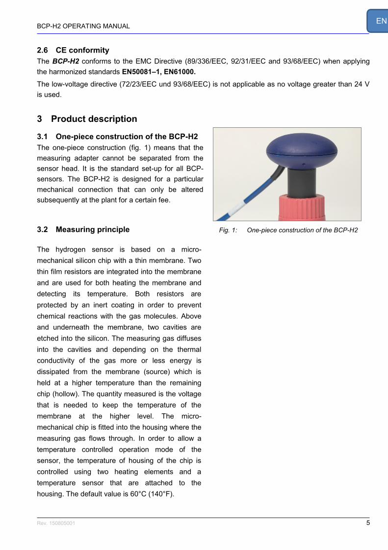
3.1 One-piece construction of the BCP-H2
The one-piece construction (fig. 1) means that the
measuring adapter cannot be separated from the
sensor head. It is the standard set-up for all BCP-
sensors. The BCP-H2 is designed for a particular
mechanical connection that can only be altered
subsequently at the plant for a certain fee.
3.2 Measuring principle
The hydrogen sensor is based on a micro-
mechanical silicon chip with a thin membrane. Two
thin film resistors are integrated into the membrane
and are used for both heating the membrane and
detecting its temperature. Both resistors are
protected by an inert coating in order to prevent
chemical reactions with the gas molecules. Above
and underneath the membrane, two cavities are
etched into the silicon. The measuring gas diffuses
into the cavities and depending on the thermal
conductivity of the gas more or less energy is
dissipated from the membrane (source) which is
held at a higher temperature than the remaining
chip (hollow). The quantity measured is the voltage
that is needed to keep the temperature of the
membrane at the higher level. The micro-
mechanical chip is fitted into the housing where the
measuring gas flows through. In order to allow a
temperature controlled operation mode of the
sensor, the temperature of housing of the chip is
controlled using two heating elements and a
temperature sensor that are attached to the
housing. The default value is 60°C (140°F).
Fig. 1: One-piece construction of the BCP-H2

BCP-H2 OPERATING MANUAL
Rev. 150805001 6
EN
4 Installation
4.1 General instructions
The BCP-H2 is protected by packaging on its way to
its application location. This secures it against the
usual transport strains. However, before installation,
check whether the device has been damaged due to
improper transport or improper storage. If the device
is damaged in any way, operation without hazards is
not possible and the device may not be installed
and taken into operation.
Check whether the enclosed materials such as
seals and screw-caps are suitable for your process
conditions (pressure, temperature, etc.).
The installation should only be performed under
supervision by a specialist and in compliance with
all applicable work safety rules.
4.2 Mechanical connection
Caution!
The sterile filter is not intended for repelling
fluids. Never install the sensor such that fluid
can run into the measuring adapter.
Ensure that the sensor head and the measuring
adapter are correctly positioned.
Protect the measuring adapter from penetration
by liquids.
After installation, check that the pipe connection
is gas-tight.
BCP-H2 OPERATING MANUAL
Rev. 150805001 7
EN
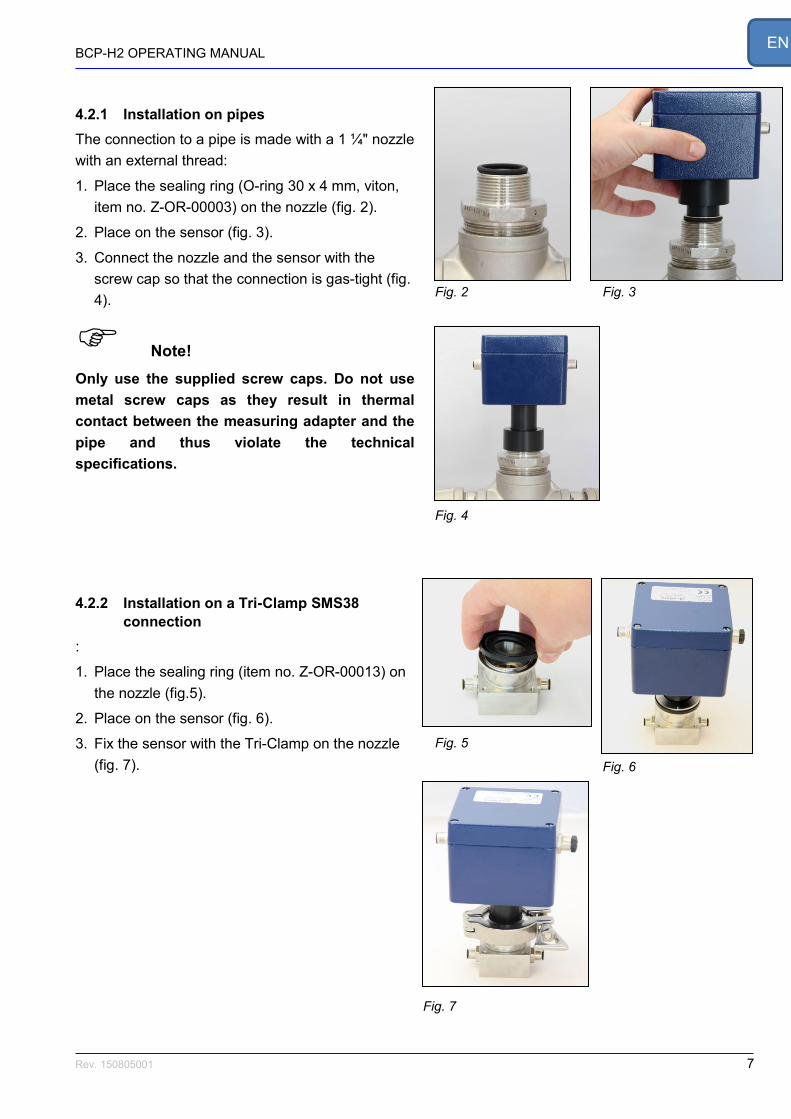
4.2.1 Installation on pipes
The connection to a pipe is made with a 1 ¼" nozzle
with an external thread:
1. Place the sealing ring (O-ring 30 x 4 mm, viton,
item no. Z-OR-00003) on the nozzle (fig. 2).
2. Place on the sensor (fig. 3).
3. Connect the nozzle and the sensor with the
screw cap so that the connection is gas-tight (fig.
4).
Note!
Only use the supplied screw caps. Do not use
metal screw caps as they result in thermal
contact between the measuring adapter and the
pipe and thus violate the technical
specifications.
4.2.2 Installation on a Tri-Clamp SMS38
connection
:
1. Place the sealing ring (item no. Z-OR-00013) on
the nozzle (fig.5).
2. Place on the sensor (fig. 6).
3. Fix the sensor with the Tri-Clamp on the nozzle
(fig. 7).
Fig. 2
Fig. 3
Fig. 4
Fig. 5
Fig. 6
Fig. 7

BCP-H2 OPERATING MANUAL
Rev. 150805001 8
EN
4.2.3 Installation on a POM flow adapter
To install the sensor on a POM flow adapter:
1. Place the sealing ring (item no. Z-OR-00004)
on the nozzle of the flow adapter
(fig. 8).
2. Place on the sensor (fig. 9).
3. Connect the flow adapter and the sensor
with the screw cap so that the connection is
gas-tight (fig. 10).
4.2.4 Installation on a stainless steel flow
adapter
To install the sensor on a stainless steel flow
adapter:
1. Place the sealing ring (item no. Z-OR-00004)
on the stainless steel connection piece (fig.
11).
2. Place on the sensor and put the screws in
place (fig. 12).
3. Fasten the 4 screws (item no. Z-XX-00007)
so that the connection is gas-tight (fig. 13).
Fig. 8
Fig. 9
Fig. 10
Fig. 11
Fig. 12
Fig. 13

BCP-H2 OPERATING MANUAL
Rev. 150805001 9
EN
4.3 Electrical connection
4.3.1 General information
Caution!
Read the installation instructions carefully to
prevent damage to the device.
Proceed step-by-step.
Only use the original plugs, cables and power
adapters.
Never connect or disconnect plugs when the
device is connected to the power supply.
The device does not have an on/off switch; it
starts operation as soon as it is connected to
the power supply.
Improper operation can result in damage to the
device.
Note!
New wide temperature sensors in aluminum
housing (WT sensors) need a power supply with
a voltage of 24V. They will not work with 12V.
Please check our individual data sheet.

BCP-H2 OPERATING MANUAL
Rev. 150805001 10
EN
4.3.2 Version 4 – 20 mA in PA6 housing
To connect the measuring device to the connection
cable of the sensor head in the PA6 housing (fig.
14), use the supplied socket and strain relief (fig.
15).
Note!
The numbering of the pins and their assignment
refer to the socket when seen from behind (fig.
16).
Remove the insulation of the cables a little as
possible to avoid short circuits in the plug
housing.
PIN 1 V+ = 12 V
PIN 2 GND
PIN 3 RS232_TXD
PIN 4 RS232_RXD
PIN 5 1-point calibration
PIN 6 4–20mA, RL < 250 Ohm
PIN 7 For internal use only
PIN 8 GND
Fig. 16: Plug assignment
1. Connect the 12 V DC power supply to pin 1
of the socket.
2. Connect GND (ground) to pin 2.
3. Connect the measuring device to pin 6
(RL < 250 Ohm) and pin 8 GND (ground).
4. Plug the sensor cable into the socket.
After around 1 hour of heating-up time, the sensor
still requires adjusting. During the heating-up time,
the sensor displays 2.3 mA. To make the adjust-
ment, expose the sensor for approx. 30 minutes
(depending on specification – see datasheet) to
CO2 or N2.
5. Afterwards, connect pin 5 to pin 8 (GND) for
5 seconds.
6. Screw on the strain relief. The sensor has
been adjusted.
Fig. 14 Fig. 15

BCP-H2 OPERATING MANUAL
Rev. 150805001 11
EN
4.3.3 RS232 serial version in PA6 housing
1. Connect the sensor to the power supply with
the cable supplied.
2. Connect the sensor to a computer using the
serial cable.
After around 1 hour of heating-up time, the sensor
still requires adjusting. To do this, expose the
sensor for approx. 30 minutes (depending on
specification – see datasheet) to CO2 or N2.
The adjustment itself is performed with the
BACVisSingle software (see BACVisSingle
operating manual).
Start the BACVisSingle software. You will find
further relevant information in the corresponding
operating manual.
Fig. 17
Fig. 18

BCP-H2 OPERATING MANUAL
Rev. 150805001 12
EN
4.3.4 Version 4 – 20 mA in aluminum housing
To connect the measuring device to the connection
cable of the sensor head in the aluminum housing
(fig. 19), use the supplied socket and strain relief
(fig. 20).
Note!
The numbering of the pins and their assignment
refer to the socket when seen from behind (fig.
21).
Remove the insulation of the cables a little as
possible to avoid short circuits in the plug
housing.
PIN 1 V+ see voltage on your individual data sheet
PIN 2 GND
PIN 3 RS232_TXD
PIN 4 RS232_RXD
PIN 5 1-point calibration
PIN 6 4–20 mA, RL < 250 Ohm
PIN 7 For internal use only
PIN 8 GND
Fig. 21: Plug assignment
1. Connect the DC power supply to pin 1 of the
socket. See voltage on your individual data
sheet.
2. Connect GND (ground) to pin 2.
3. Connect the measuring device to pin 6
(RL < 250 Ohm) and pin 8 GND (ground).
4. Plug the sensor cable into the socket.
After around 1 hour of heating-up time, the sensor
still requires adjusting. During the heating-up time,
the sensor displays 2.3 mA. To make the adjust-
ment, expose the sensor for approx. 30 minutes
(depending on specification – see datasheet) to
CO2 or N2.
5. Afterwards, connect pin 5 to pin 8 (GND) for
5 seconds.
Fig. 20
Fig. 19

BCP-H2 OPERATING MANUAL
Rev. 150805001 13
EN
6. Screw on the strain relief. The sensor has been
adjusted.
4.3.5 RS232 serial version in aluminum housing
1. Connect the sensor to the power supply with
the cable supplied.
2. Connect the sensor to a computer using the
serial cable.
After around 1 hour of heating-up time, the sensor
still requires adjusting. To do this, expose the
sensor for approx. 30 minutes (depending on
specification – see datasheet) to CO2 or N2.
The adjustment itself is performed with the
BACVisSingle software (see BACVisSingle
operating manual).
Start the BACVisSingle software. You will find all of
the further relevant information in the corresponding
operating manual.
1 = +12V or + 24V, please see you data sheet
2 = 0 V
3 = RS232_RxD
4 = RS232_TxD
5 = RS232_GND = PE
PE = ground
Fig. 23: Plug assignment
Fig. 22

BCP-H2 OPERATING MANUAL
Rev. 150805001 14
EN
4.3.6 Connection via BACCom12
The BACCom12 connection box is an electronic
multiplexer with an integrated pressure sensor. It
facilitates the connection of up to 12 sensor heads.
Communication with a PC can be switched between
RS232 or Ethernet.
The individual connections are explained in the
following table:
Designation Description
A RJ45 RJ45 socket for connecting the sensors
B LED Operating display when a voltage is present
C Sub D 9 pin Data transmission to the PC
D Switch Switches between RS232 and Ethernet
F RJ45 Ethernet connection
G Power socket
12 V 3.75 A, only use the supplied power adapter
H Box reset Resets the box; does not effect the sensors
K M8 4 pin socket
4-pin connection sockets A–D for additional boxes
Caution!
To prevent damage to the device, only use the
supplied power adapter and the supplied cable.
Never disconnect or connect the connection
plugs on the sensor heads when the BACCom12
is switched on.
1. Connect all sensor heads with the
BACCom12.
2. Connect the supplied power adapter to the
power socket G.
3. Plug the power plug of the power adapter
into the socket.
After a heating-up time of approx. 1 hour, the
measuring system is ready for operation.
Fig. 25: Connections on the BACCom12
Fig. 24: Front of the BACCom12

BCP-H2 OPERATING MANUAL
Rev. 150805001 15
EN
4. Connect the BACCom12 to the PC or
network via the Ethernet port E,
or connect the
BACCom12 via the RS232 output C with the
supplied cable to the serial interface of the
computer.
5. Select the corresponding interface with the
switch D.
After around 1 hour of heating-up time, the sensor
still requires adjusting. To do this, expose the
sensor for approx. 30 minutes (depending on
specification – see datasheet) to CO2 or N2.
Adjustment of the sensors is performed with the
BACVis software. Start the corresponding software.
You will find all further information in the software
instructions.
After initial commissioning, the measuring device
can remain switched on constantly, meaning that
the heating-up time is not required before every
measuring.

BCP-H2 OPERATING MANUAL
Rev. 150805001 16
EN
4.4 Cross-sensitivity to other gases
Due to the thermal conductivity measuring principle
of the BCP-H2 each sensor has a specific cross-
sensitivity to other gases. The value of the deviation
depends on the specifications of the used sensor and
the gas mixture applied. Every H2 senor has been
pre-calibrated at the factory for a specific dry gas
mixture. Exact specifications before the first factory
calibration are therefore decisive for the subsequent
measurement results. Due to this a BCP-H2 cannot
be switched to a different process with other gas
components. Please contact us if you want to use it
in different gas mixtures.
For detailed information on the cross-sensitivity and
the effect and your individual sensor, please ask us
directly.

BCP-H2 OPERATING MANUAL
Rev. 150805001 17
EN
5 Maintenance We recommend sending the device to BlueSens for
annual maintenance, checking and calibration of the
sensors.
5.1 1-point calibration
Once monthly, or after each connection and
disconnection of the sensor head and measuring
adapter, the sensor head must be exposed for
approx. 30 minutes (depending on specifications,
see datasheet) to CO2 or N2.
Afterwards, connect pin 5 to pin 8 on the connection
cable for 5 seconds, or, if present on the sensor,
press the blue button for 5 seconds (fig. 26).
For the serial version, the adjustment can be made
using the BACVis software.
5.2 Recalibration
The sensor should be sent back to the manufacturer
or an authorized dealer for annual recalibration.
You can get further information for our annual
maintenance service Blue4Care incl. extension of
the warranty up to 6 years on our homepage:
http://www.bluesens.de
and then in the area:
ServiceBlue4Care
Fig. 26
BCP-H2 OPERATING MANUAL
Rev. 150805001 18
EN
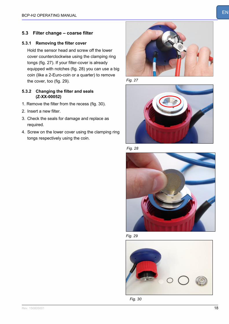
5.3 Filter change – coarse filter
5.3.1 Removing the filter cover
Hold the sensor head and screw off the lower
cover counterclockwise using the clamping ring
tongs (fig. 27). If your filter-cover is already
equipped with notches (fig. 28) you can use a big
coin (like a 2-Euro-coin or a quarter) to remove
the cover, too (fig. 29).
5.3.2 Changing the filter and seals
(Z-XX-00052)
1. Remove the filter from the recess (fig. 30).
2. Insert a new filter.
3. Check the seals for damage and replace as
required.
4. Screw on the lower cover using the clamping ring
tongs respectively using the coin.
Fig. 27
Fig. 30
Fig. 28
Fig. 29

BCP-H2 OPERATING MANUAL
Rev. 150805001 19
EN
6 Appendix
6.1 Calibration table
Complete calibration can only be conducted by BlueSens. Monthly 1-point calibration can be performed
as described in chapter 5.1. The adjustment must also be made each time the sensor head and the
measuring adapter are disconnected from each other.
Fill out the table below when this is performed.
Date Procedure Conditions Name Signature
Complete calibration 25 °C, 1 bar BlueSens
1-point calibration

BCP-H2 OPERATING MANUAL
Rev. 150805001 20
EN
6.2 Technical data
See enclosed datasheet.

BCP-H2 OPERATING MANUAL
Rev. 150805001 21
EN
EG-Konformitätserklärung EC Declaration of conformity
Hiermit erklären wir, dass unser Produkt, Typ:
We hereby declare that our product, type;
BCP-H2
folgenden einschlägigen Bestimmungen entspricht:
complies with the following relevant provisions:
Niederspannungsrichtlinie (72/23/EWG und 93/68/EWG) findet keine Anwendung, da keine
Spannung größer 24 V genutzt wird.
Low voltage guideline (72/23/EEC and 93/68/EEC) is not applicable as no voltage higher than
24 V is used.
EMV-Richtlinie (89/336/EWG, 92/31/EWG und 93/68/EWG)
EMC guideline (89/336/EEC, 92/31/EEC and 93/68/EEC)
Angewendete harmonisierte Normen, insbesondere:
Applied harmonized standards, in particular:
EN50081–1 EN61000 Dr. Holger Mueller, Dr. Udo Schmale BlueSens gas sensor GmbH Snirgelskamp 25 D-45699 Herten, Germany Phone +492366 / 4995-500 Fax +492366 / 4995-599 Dr. Udo Schmale www.bluesens.com

BCP-H2 Betriebsanleitung
21 Rev. 150805001
Betriebsanleitung
BCP-H2
Aluminiumgehäuse
(IP65) PA Gehäuse

BCP-H2 Bedienungsanleitung
22 Rev. 150805001
DE

BCP-H2 Bedienungsanleitung
23 Rev. 150805001
DE
Inhalt
1 ZU DIESEM DOKUMENT ................................................................................................................. 24
1.1 Funktion ....................................................................................................................................................... 24
1.2 Zielgruppe ................................................................................................................................................... 24
1.3 Benutzte Symbole ....................................................................................................................................... 24
2 ZU IHRER SICHERHEIT .................................................................................................................. 25
2.1 Allgemeines ................................................................................................................................................. 25
2.2 Autorisiertes Personal ................................................................................................................................. 25
2.3 Bestimmungsgemäße Verwendung ............................................................................................................ 25
2.4 Warnung vor Fehlgebrauch ......................................................................................................................... 25
2.5 Allgemeine Sicherheitshinweise .................................................................................................................. 25
2.6 CE Konformität ............................................................................................................................................ 26
3 PRODUKTBESCHREIBUNG ........................................................................................................... 26
3.1 BCP-H2 in 1-teiligem Aufbau ...................................................................................................................... 26
3.2 Messprinzip ................................................................................................................................................. 26
4 INSTALLATION ................................................................................................................................ 28
4.1 Allgemeine Instruktionen ............................................................................................................................. 28
4.2 Mechanischer Anschluss ............................................................................................................................ 28
4.2.1 Installation an Rohrleitungen .................................................................................................................. 29
4.2.2 Installation am Tri-Clamp-Anschluss ..................................................................................................... 29
4.2.3 Installation am Durchflussadapter POM ................................................................................................ 30
4.2.4 Installation am Flussadapter aus Edelstahl ........................................................................................... 30
4.3 Elektrischer Anschluss ................................................................................................................................ 31
4.3.1 Allgemeines ............................................................................................................................................ 31
4.3.2 Version 4 – 20 mA im PA6-Gehäuse ..................................................................................................... 32
4.3.3 Serielle Version RS232 im PA6 Gehäuse .............................................................................................. 33
4.3.4 Version 4 – 20 mA im Alu-Gehäuse ....................................................................................................... 34
4.3.5 Serielle Version RS232 im Alugehäuse ................................................................................................. 35
4.3.6 Anschluss über BACCom12 ................................................................................................................... 36
4.4 Querempfindlichkeit zu anderen Gasen ...................................................................................................... 38
5 WARTUNG ....................................................................................................................................... 39
5.1 1-Punkt-Kalibration ...................................................................................................................................... 39
5.2 Rekalibration ............................................................................................................................................... 39
5.4 Filterwechsel – Grobfilter ............................................................................................................................ 40
5.4.1 Filterabdeckung entfernen ..................................................................................................................... 40
5.4.2 Filter und Dichtungen wechseln (Z-XX-00052) ..................................................................................... 40
6 ANHANG .......................................................................................................................................... 41
6.1 Kalibrationstabelle ....................................................................................................................................... 41
6.2 Technische Daten ....................................................................................................................................... 42
BCP-H2 Bedienungsanleitung
24 Rev. 150805001
DE
1 Zu diesem Dokument
1.1 Funktion
Die vorliegende Betriebsanleitung liefert Ihnen alle
erforderlichen Informationen für eine schnelle
Inbetriebnahme und einen sicheren Betrieb des
BCP-H2. Lesen Sie diese Betriebsanleitung deshalb
vor Inbetriebnahme.
1.2 Zielgruppe
Diese Betriebsanleitung richtet sich an ausgebildetes
Fachpersonal. Der Inhalt dieser Anleitung muss dem
Fachpersonal zugänglich gemacht und umgesetzt
werden.
1.3 Benutzte Symbole
Gefahr!
Dieses Symbol weist auf eine mögliche
und gefährliche Situation hin.
Nichtbeachten dieses
Sicherheitshinweises kann
Personenschäden zur Folge haben.
Vorsicht!
Dieses Symbol weist auf eine mögliche
Sachbeschädigung hin.
Hinweis!
Dieses Symbol kennzeichnet hilfreiche
Zusatzinformationen.
1 Handlungsfolge
Vorangestellte Zahlen kennzeichnen
aufeinander folgende Handlungsschritte.
BCP-H2 Bedienungsanleitung
25 Rev. 150805001
DE
2 Zu Ihrer Sicherheit
2.1 Allgemeines
Der BCP-H2 hat unser Werk in geprüftem und
betriebsbereitem Zustand verlassen.
Bitte lesen Sie vor Montage und Inbetriebnahme des
Gerätes diese Betriebsanleitung sorgfältig durch. Die
Betriebsanleitung beinhaltet Sicherheitshinweise, die
beachtet werden müssen, um einen gefahrlosen
Betrieb zu gewährleisten.
Das Gerät darf niemals unter Bedingungen betrieben
werden, die nicht den angegebenen Spezifikationen
und den Angaben auf dem Typenschild entsprechen.
Wartung und Instandsetzung darf nur von sach- und
fachkundig geschulten Personen vorgenommen
werden, die mit den damit verbundenen Gefahren
und Garantiebestimmungen vertraut sind.
2.2 Autorisiertes Personal
Sämtliche in dieser Betriebsanleitung beschriebenen
Handhabungen dürfen nur durch ausgebildetes und
vom Anlagenbetreiber autorisiertes Fachpersonal
durchgeführt werden. Darüber hinaus gehende
Eingriffe in das Gerät dürfen aus Sicherheits- und
Gewährleistungsgründen nur durch Personal der
BlueSens gas sensor GmbH vorgenommen werden.
2.3 Bestimmungsgemäße Verwendung
Der BCP-H2 ist ein Gassensor zur Messung von
Wasserstoffgaskonzentrationen im angegeben
Konzentrationsbereich von binären Gasgemischen
und unter den Bedingungen wie in den technischen
Daten beschrieben.
2.4 Warnung vor Fehlgebrauch
Der BCP-H2 darf nicht als Sicherheitsbauteil zur
Gasüberwachung in Anlagen oder als Gaswarngerät
eingesetzt werden.
2.5 Allgemeine Sicherheitshinweise
Bei nicht sachgerechter oder nicht
bestimmungsgemäßer Verwendung können von
diesem Gerät anwendungsspezifische Gefahren
ausgehen.

BCP-H2 Bedienungsanleitung
26 Rev. 150805001
DE
Gefahr!
Durch falsche Montage oder Einstellung besteht
Vergiftungsgefahr oder Explosionsgefahr.
Überprüfen Sie alle Anschlüsse nach der
Montage auf Dichtigkeit.
2.6 CE Konformität
Der BCP-H2 ist konform mit EMV-Richtlinie
(89/336/EWG, 92/31/EWG und 93/68/EWG) unter
Anwendung der harmonisierten Normen EN50081–1,
EN61000.
Die Niederspannungsrichtlinie (72/23/EWG und
93/68/EWG) findet keine Anwendung, da keine
Spannung größer 24V genutzt wird.
3 Produktbeschreibung
3.1 BCP-H2 in 1-teiligem Aufbau
Bei dem 1-teiligen Aufbau (Abb. 1) können
Messadapter und Sensorkopf nicht voneinander
getrennt werden. Der BCP-H2 ist jeweils für eine
bestimmte mechanische Anbindung ausgelegt, die
nachträglich nur kostenpflichtig im Werk geändert
werden kann.
3.2 Messprinzip Das Messprinzip des Wasserstoffsensors basiert auf
der Wärmeleitfähigkeitsmessung.
Der Wasserstoffsensor besteht aus einem
mikromechanischen Silikonchip mit einer dünnen
Membran. Zwei Dünnfilmwiderstände sind in diese
Membran integriert und werden durch einen
angelegten Strom auf eine definierte Temperatur
gebracht. Ober- und unterhalb der Membran sind
zwei Aushöhlungen in das Silizium geätzt, die von
den Molekülen des Messgases nur durch Diffusion
erreicht werden können. Die elektrische Spannung,
die benötigt wird, um die Temperatur der Membran
konstant zu halten, ist dann ein Maß für die
Abb. 1

BCP-H2 Bedienungsanleitung
27 Rev. 150805001
DE
Wärmeleitfähigkeit des Messgases. Der mikro-
mechanische Siliziumchip ist in eine
Edelstahlarmatur eingepasst, durch die das Messgas
fließt. Beide Widerstände sind mit einer inneren
Schutzschicht abgedeckt, damit an ihnen keine
chemischen Umsetzungen der Messgasmoleküle
erfolgt. Um den Einfluss der Umgebungstemperatur
zu minimieren, wird die Temperatur der
Edelstahlarmatur mittels zweier Widerstandsheizer
und eines Temperaturfühlers konstant gehalten. Die
Regelelektronik hierzu befindet sich auf einer Platine,
die unterhalb der Armatur befestigt ist. Der
voreingestellte Wert beträgt 60°C.

BCP-H2 Bedienungsanleitung
28 Rev. 150805001
DE
4 Installation
4.1 Allgemeine Instruktionen
Der BCP-H2 wurde auf dem Weg zum Einsatzort
durch eine Verpackung geschützt. Dabei sind die
üblichen Transportbeanspruchungen abgesichert.
Prüfen Sie dennoch vor der Installation, ob das
Gerät durch unsachgemäßen Transport oder
unsachgemäße Lagerung beschädigt worden ist.
Bei eventuellen Beschädigungen ist ein gefahrloser
Betrieb nicht möglich, das Gerät darf nicht installiert
und in Betrieb genommen werden.
Prüfen Sie, ob die beiliegenden Materialien wie
Dichtungen und Schraubkappen für Ihre
Prozessbedingungen (Druck, Temperatur, etc.)
geeignet sind.
Der Einbau sollte ausschließlich unter
fachmännischer Anleitung und unter
Berücksichtigung der entsprechenden anerkannten
Regeln für Arbeitssicherheit erfolgen.
4.2 Mechanischer Anschluss
Vorsicht!
Der Sterilfilter dient nicht zum Abhalten von
Flüssigkeit. Darum niemals den Sensor so
installieren, dass Flüssigkeit in den
Messadapter laufen kann.
Falls Wasser in den Messadapter eingedrungen
ist, diesen für mindestens 12 Stunden bei max.
80°C im Trockenschrank oder auf einer
Heizplatte trockenen.
Achten Sie auf die korrekte Positionierung von
Sensorkopf und Messadapter.
Schützen Sie den Messadapter vor
eindringender Feuchtigkeit.
Prüfen Sie nach der Installation die
Gasdichtigkeit der Rohrleitung.

BCP-H2 Bedienungsanleitung
29 Rev. 150805001
DE
4.2.1 Installation an Rohrleitungen
Der Anschluss an der Rohrleitung erfolgt über
einen 1 ¼” Stutzen mit Außengewinde:
1. Dichtring (O-Ring 30 x 4 mm, Viton, Artikel-Nr.
Z-OR-00003) auf dem Stutzen platzieren (Abb.
2).
2. Sensor aufsetzen (Abb. 3).
3. Stutzen und Sensor mit der Schraubkappe
gasdicht verbinden (Abb. 4).
Hinweis! Benutzen Sie ausschließlich die mitgelieferten
Schraubkappen. Benutzen Sie keine
Schraubkappen aus Metall, sie führen zu
thermischem Kontakt zwischen Sensor und
Rohrleitung, und die technischen Spezifikationen
werden nicht eingehalten.
4.2.2 Installation am Tri-Clamp-Anschluss
Installation an einem Tri-Clamp-Anschluss:
1. Dichtung (Artikel-Nr. Z-OR-00013) auf dem
Stutzen platzieren (Abb. 5).
2. Sensor passend aufsetzen.
(Abb. 6).
3. Sensor mit der Tri-Clamp auf dem Stutzen
fixieren (Abb. 7).
Abb. 2 Abb. 3
Abb. 4
Abb. 5
Abb. 6
Abb. 7

BCP-H2 Bedienungsanleitung
30 Rev. 150805001
DE
4.2.3 Installation am Durchflussadapter POM
Zur Installation des Sensorkopfes am
Durchflussadapter aus POM:
1. Dichtring (Artikel-Nr. Z-OR-00004) auf dem
Stutzen des Durchflussadapters platzieren
(Abb. 8).
2. Sensor aufsetzen (Abb. 9).
3. Durchflussadapter und Sensor mit der
Schraubkappe gasdicht verbinden (Abb. 10).
4.2.4 Installation am Flussadapter aus Edelstahl
Zur Installation des Sensorkopfes am Flussadapter
aus Edelstahl:
1. Dichtring (Artikel-Nr. Z-OR-00004) auf dem
Anschlussstück aus Edelstahl platzieren (Abb.
11).
2. Sensor aufsetzen (Abb. 12).
3. Die 4 Schrauben (Artikel-Nr. Z-XX-00007)
befestigen und dadurch eine gasdichte
Verbindung herstellen (Abb. 13).
Hinweis!Zumeist sind diese Flussadapter bei
Erstauslieferung bereits am Sensor montiert!
Abb. 8
Abb. 9
Abb. 10
Abb. 11
Abb. 12
Abb. 13
BCP-H2 Bedienungsanleitung
31 Rev. 150805001
DE
4.3 Elektrischer Anschluss
4.3.1 Allgemeines
Vorsicht!
Lesen Sie die Installationshinweise sorgfältig,
um Schäden am Gerät zu vermeiden.
Gehen Sie schrittweise vor.
Benutzen Sie nur die originalen Stecker, Kabel
und Netzgeräte.
Niemals Stecker anstecken oder abziehen, wenn
das Gerät an die Spannungsversorgung
angeschlossen ist.
Das Gerät hat keinen Ein/Aus-Schalter, es ist
direkt nach Anschluss an die
Spannungsversorgung in Betrieb.
Fehlbedienung kann zu Schäden am Gerät
führen.
Hinweis!
Neue Weittemperatursensoren in
Aluminiumgehäuse (WT-Sensoren) benötigen
eine Stromversorgung von 24V. Die neuen WT-
Sensoren funktionieren nicht mit 12V. Bitte
beachten Sie das Datenblatt für den jeweiligen
Sensor.
BCP-H2 Bedienungsanleitung
32 Rev. 150805001
DE
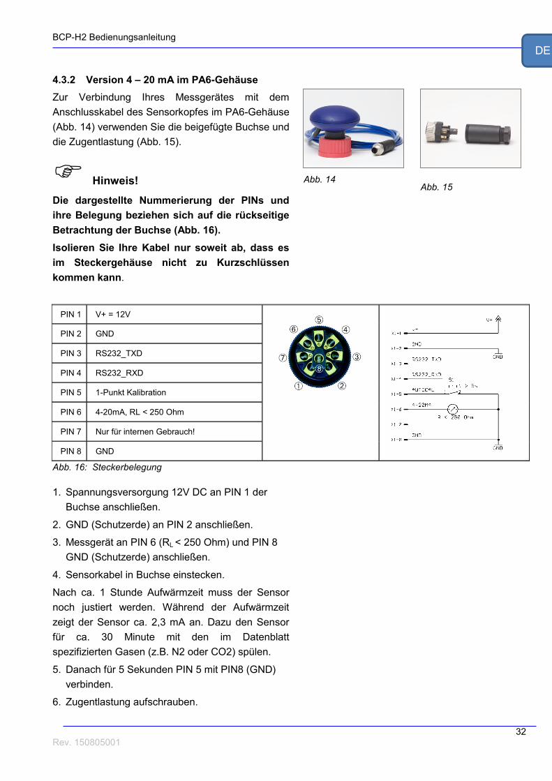
4.3.2 Version 4 – 20 mA im PA6-Gehäuse
Zur Verbindung Ihres Messgerätes mit dem
Anschlusskabel des Sensorkopfes im PA6-Gehäuse
(Abb. 14) verwenden Sie die beigefügte Buchse und
die Zugentlastung (Abb. 15).
Hinweis!
Die dargestellte Nummerierung der PINs und
ihre Belegung beziehen sich auf die rückseitige
Betrachtung der Buchse (Abb. 16).
Isolieren Sie Ihre Kabel nur soweit ab, dass es
im Steckergehäuse nicht zu Kurzschlüssen
kommen kann.
PIN 1 V+ = 12V
PIN 2 GND
PIN 3 RS232_TXD
PIN 4 RS232_RXD
PIN 5 1-Punkt Kalibration
PIN 6 4-20mA, RL < 250 Ohm
PIN 7 Nur für internen Gebrauch!
PIN 8 GND
Abb. 16: Steckerbelegung
1. Spannungsversorgung 12V DC an PIN 1 der
Buchse anschließen.
2. GND (Schutzerde) an PIN 2 anschließen.
3. Messgerät an PIN 6 (RL < 250 Ohm) und PIN 8
GND (Schutzerde) anschließen.
4. Sensorkabel in Buchse einstecken.
Nach ca. 1 Stunde Aufwärmzeit muss der Sensor
noch justiert werden. Während der Aufwärmzeit
zeigt der Sensor ca. 2,3 mA an. Dazu den Sensor
für ca. 30 Minute mit den im Datenblatt
spezifizierten Gasen (z.B. N2 oder CO2) spülen.
5. Danach für 5 Sekunden PIN 5 mit PIN8 (GND)
verbinden.
6. Zugentlastung aufschrauben.
Abb. 14 Abb. 15

BCP-H2 Bedienungsanleitung
33 Rev. 150805001
DE
Der Sensor ist jetzt justiert.
4.3.3 Serielle Version RS232 im PA6 Gehäuse
1. Sensor an die beiliegende
Spannungsversorgung (12 V!) anschließen.
2. Sensor mit dem seriellen Kabel an einen
Computer anschließen.
Nach ca. 1 Stunde Aufwärmzeit muss der Sensor
noch justiert werden. Dazu den Sensor für ca. 30
Minute mit den im Datenblatt spezifizierten Gasen
(z.B. N2 oder CO2) spülen.
Die Justierung selber erfolgt über die Software
BACVisSingle (siehe Bedienungsanleitung
BACVisSingle).
Starten Sie die Software BACVisSingle. Alle
weiteren Informationen finden Sie in der
dazugehörigen Bedienungsanleitung.
Abb. 17
Abb. 18

BCP-H2 Bedienungsanleitung
34 Rev. 150805001
DE
4.3.4 Version 4 – 20 mA im Alu-Gehäuse
Zur Verbindung Ihres Messgerätes mit dem
Anschlusskabel des Sensorkopfes im Alu-Gehäuse
(Abb. 19) verwenden Sie die beigefügte Buchse und
die Zugentlastung (Abb. 20).
Hinweis!
Die dargestellte Nummerierung der PINs und
ihre Belegung beziehen sich auf die rückseitige
Betrachtung der Buchse (Abb. 21).
Isolieren Sie Ihre Kabel nur soweit ab, dass es
im Steckergehäuse nicht zu Kurzschlüssen
kommen kann.
PIN 1 V+ = 12V oder 24V, siehe Datenblatt!
PIN 2 GND
PIN 3 RS232_TXD
PIN 4 RS232_RXD
PIN 5 1-Punkt Kalibration
PIN 6 4-20mA, RL < 250 Ohm
PIN 7 Nur für internen Gebrauch!
PIN 8 GND
Abb. 21: Steckerbelegung
1. Spannungsversorgung 12V – 24 V DC an PIN 1
der Buchse anschließen. 12 oder 24 V DC an
PIN 1 der Buchse anschließen. Für die passende
Spannung beachten Sie bitte unbedingt Ihr
spezifisches Datenblatt.
2. GND (Schutzerde) an PIN 2 anschließen.
3. Messgerät an PIN 6 (RL < 250 Ohm) und PIN 8
GND (Schutzerde) anschließen.
4. Sensorkabel in Buchse einstecken.
Nach ca. 1 Stunde Aufwärmzeit muss der Sensor
noch justiert werden. Während der Aufwärmzeit
zeigt der Sensor ca. 2,3 mA an. Dazu den Sensor
für ca. 30 Minute mit den im Datenblatt
spezifizierten Gasen (z.B. N2 oder CO2) spülen.
5. Danach für 5 Sekunden PIN 5 mit PIN8 (GND)
Abb. 20
Abb. 19
BCP-H2 Bedienungsanleitung
35 Rev. 150805001
DE
verbinden.
6. Zugentlastung aufschrauben.
Der Sensor ist jetzt justiert.
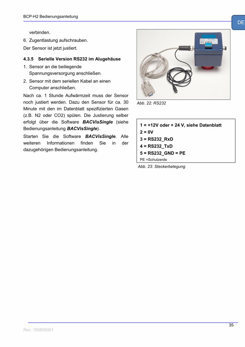
4.3.5 Serielle Version RS232 im Alugehäuse
1. Sensor an die beiliegende
Spannungsversorgung anschließen.
2. Sensor mit dem seriellen Kabel an einen
Computer anschließen.
Nach ca. 1 Stunde Aufwärmzeit muss der Sensor
noch justiert werden. Dazu den Sensor für ca. 30
Minute mit den im Datenblatt spezifizierten Gasen
(z.B. N2 oder CO2) spülen. Die Justierung selber
erfolgt über die Software BACVisSingle (siehe
Bedienungsanleitung BACVisSingle).
Starten Sie die Software BACVisSingle. Alle
weiteren Informationen finden Sie in der
dazugehörigen Bedienungsanleitung.
1 = +12V oder + 24 V, siehe Datenblatt
2 = 0V
3 = RS232_RxD
4 = RS232_TxD
5 = RS232_GND = PE
PE =Schutzerde
Abb. 23: Steckerbelegung
Abb. 22: RS232

BCP-H2 Bedienungsanleitung
36 Rev. 150805001
DE
4.3.6 Anschluss über BACCom12
Die Anschaltbox BACCom12 ist ein elektronischer
Multiplexer mit integriertem Drucksensor. Sie
ermöglicht den Anschluss von bis zu 12
Sensorköpfen.
Die Kommunikation mit einem PC kann umschaltbar
über RS232 oder Ethernet erfolgen.
Die Erklärung der einzelnen Anschlüsse ist in der
folgenden Tabelle aufgeführt:
Bezeichnung Beschreibung
A RJ45 RJ45 Buchse zum Anschluss der Sensoren
B LED Betriebsanzeige wenn Spannung anliegt
C Sub-D 9 pol Datenübertragung zum PC
D Schalter Umschalter zwischen RS232 und Ethernet
F RJ45 Ethernetanschluss
G Netzbuchse 12 V 3,75A, nur mitgeliefertes Netzteil benutzen
H Boxreset Reset der Box, Sensoren bleiben unbeeinflusst
K M8 4 pol Buchse
4-polige Anschlussbuchsen A-D für Zusatzboxen
Vorsicht!
Um Beschädigungen am Gerät zu vermeiden,
dürfen nur das mitgelieferten Netzteil und die
mitgelieferten Kabel verwendet werden.
Niemals die Anschlussstecker der Sensorköpfe
bei eingeschalteter BACCom12 aufstecken oder
abziehen.
1. Alle Sensorköpfe mit BACCom12 verbinden.
2. Mitgeliefertes Netzteil an die Netzbuchse G
anschließen.
3. Netzstecker des Netzteils in die Steckdose
stecken.
Nach ca. 1 Stunde Aufwärmzeit ist das Messsystem
Abb. 25: Anschlüsse am BACCom12
Abb. 24: Vorderseite BACCom12

BCP-H2 Bedienungsanleitung
37 Rev. 150805001
DE
einsatzbereit.
4. BACCom12 über den Ethernetport E mit PC
oder Netzwerk verbinden,
oder
BACCom12 über den RS232 Ausgang C mit
dem beiliegenden Kabel an die serielle
Schnittstelle des Computers anschließen.
5. Die jeweilige Schnittstelle mit dem Umschalter D
auswählen.
Nach ca. 1 Stunde Aufwärmzeit muss der Sensor
noch justiert werden. Dazu den Sensor für ca. 30
Minute mit den im Datenblatt spezifizierten Gasen
(z.B. N2 oder CO2) spülen.
Die Justierung der Sensoren erfolgt über die
Software BACVis. Starten Sie dazu die jeweilige
Software, alle weiteren Informationen finden Sie in
den Softwareanleitungen.
Nach der erstmaligen Inbetriebnahme kann das
Messsystem dauerhaft eingeschaltet bleiben, so
dass nicht vor jeder Messung die Aufwärmzeit
eingehalten werden muss.

BCP-H2 Bedienungsanleitung
38 Rev. 150805001
DE
4.4 Querempfindlichkeit zu anderen Gasen
Durch das Wärmeleitfähigkeits-Messprinzip des
Sensors hat jeder BCP-H2 eine spezifische
Querempfindlichkeit zu anderen Gasen. Der Wert
der Abweichung hängt von den Messspezifikationen
des Sensors und dem eingesetzten Prozessgas ab.
In binären Gasgemischen kann der BCP-H2 am
besten messen. Jeder H2-Senor ist ab Werk für ein
bestimmtes trockenes Gasgemisch vorkalibriert
worden. Die genaue Spezifikation der
Einsatzbedingungen ist daher schon vor der
Erstkalibration im Werk ausschlaggebend für die
Zuverlässigkeit der späteren Messergebnisse. Ein
BCP-H2 kann von daher auch nicht einfach in
einem anderen Prozess mit abweichenden
Gaskomponenten eingesetzt werden. Bitte
sprechen Sie uns an, wenn Sie den BCP-H2 in
anderen Gasgemischen einsetzten möchten!
Für genaue Informationen zu der
Querempfindlichkeit und den Effekt und Ihrem
individuellen Sensor, sprechen Sie uns auch bitte
direkt an!

BCP-H2 Bedienungsanleitung
39 Rev. 150805001
DE
5 Wartung Zur jährlichen Wartung, Kontrolle und Kalibration
der Sensoren schlagen wir die Übersendung an
BlueSens vor.
5.1 1-Punkt-Kalibration
Einmal im Monat muss dieser für ca. 30 Minuten je
nach Spezifikation mit den im Datenblatt
spezifizierten Gasen (z.B. N2 oder CO2) gespült
werden.
Anschließend am Anschlusskabel für 5 Sekunden
PIN 5 mit PIN 8 (GND) verbinden oder, falls am
Sensor vorhanden, blauen Taster für 5 Sekunden
betätigen (Abb. 26).
Im Falle der seriellen Version kann die Justierung
über die Software BACVis / BACVisSingle
durchgeführt werden.
Nach der erstmaligen Inbetriebnahme kann das
Messsystem dauerhaft eingeschaltet bleiben, so
dass nicht vor jeder Messung die Aufwärmzeit
eingehalten werden muss.
5.2 Rekalibration
Zur jährlichen Rekalibration sollte der Sensor zum
Hersteller oder einem autorisierten Händler
zurückgesendet werden.
Weitere Informationen zum kostengünstigen,
jährlichen Inspektionsservice Blue4Care inkl. Gar-
antieverlängerung auf bis zu 6 Jahre, können
Sie unter
http://www.bluesens.de
im Bereich ServiceBlue4Care
herunterladen.
Abb. 26

BCP-H2 Bedienungsanleitung
40 Rev. 150805001
DE
5.4 Filterwechsel – Grobfilter
5.4.1 Filterabdeckung entfernen
Sensor festhalten und untere Abdeckung gegen den
Uhrzeigersinn mit Hilfe der Klemmringzange
abschrauben (Abb. 27). Falls Ihr Sensor bereits
über die Einkerbungen in der Filterabdeckung
verfügt (Abb. 28), können Sie die Abdeckung
alternativ auch mit einer großen Münze, wie etwa
einer 2-Euromünze, aufschrauben (Abb. 29).
5.4.2 Filter und Dichtungen wechseln
(Z-XX-00052)
1. Filter aus der Vertiefung entfernen (Abb. 30).
2. Neuen Filter einsetzen.
3. Dichtungen auf Beschädigungen prüfen und
bei Bedarf ersetzen.
4. Untere Abdeckung mit Hilfe der
Klemmringzange bzw. mit der Münze wieder
aufschrauben.
Abb. 27
Abb. 30
Abb. 28
Abb. 29

BCP-H2 Bedienungsanleitung
41 Rev. 150805001
DE
6 Anhang
6.1 Kalibrationstabelle
Die vollständige Kalibration kann nur von BlueSens durchgeführt werden. Die monatliche
1-Punkt Kalibration kann wie in Kapitel 5.6 durchgeführt werden. Bei Trennung von Sensorkopf und
Messadapter ist diese Justierung ebenfalls durchzuführen.
Dazu ist die untenstehende Tabelle auszufüllen.
Datum Prozedur Bedingungen Name Unterschrift
Komplette Kalibration 25°C, 1 bar BlueSens
1-Punkt Kalibration

BCP-H2 Bedienungsanleitung
42 Rev. 150805001
DE
6.2 Technische Daten
Siehe beiliegendes Datenblatt!

BCP-H2 Bedienungsanleitung
43 Rev. 150805001
DE
EG-Konformitätserklärung EC Declaration of conformity
Hiermit erklären wir, dass unser Produkt, Typ:
We hereby declare that our product, type;
BCP-H2
folgenden einschlägigen Bestimmungen entspricht:
complies with the following relevant provisions:
Niederspannungsrichtlinie (72/23/EWG und 93/68/EWG) findet keine Anwendung, da keine
Spannung größer 24V genutzt wird.
Low voltage guidelines (72/23/EEC and 93/68/EEC) is not applied because no voltage higher
than 24 V is used.
EMV-Richtlinie (89/336/EWG, 92/31/EWG und 93/68/EWG)
EMC guideline (89/336/EEC, 92/31/EEC and 93/68/EEC)
Angewendete harmonisierte Normen, insbesondere:
Applied harmonized standards, in particular:
EN50081–1 EN61000 BlueSens gas sensor GmbH Snirgelskamp 25 45699 Herten, Germany Phone: 49 2366 / 4995-500 Fax: 49 2366 / 4995-599 www.bluesens.de Dr. Udo Schmale