bdm2_compartmentation.pdf
TRANSCRIPT

for the FireProtection ofBuildings
CORE DOCUMENT
COMPARTMENTATION
Compartmentation CORE 2 1/2/08 11:34 Page 1
First published byThe Fire Protection AssociationLondon RoadMoreton in MarshGloucestershire GL56 0RH
ISBN: 1 902790 58 8
Tel: +44 (0)1608 812 500Fax: +44 (0)1608 812 501 E mail: [email protected]: www.thefpa.co.uk
© 2008 Fire Protection Associationon behalf of Insurers’ Fire ResearchStrategy
Copies of this document and othersin the Design Guide series may beobtained from the publicationsdepartment of the FPA, at theabove address.
Printed by Modern ColourSolutions 1.0/02.08
FPA Design Guide: Essential PrinciplesThe objectives of the Design Guide are to:• reduce the likelihood of fire, either accidental or malicious;• minimise the effect of fire on a business;• protect the buildings within a business; and• maintain the health and safety of those in and around the building (including
firefighters).
This objective will be achieved by addressing essential principles to be followed in the designand construction of commercial and industrial premises.
The essential principles are:Reaction in the event of fire:
1. The building shall be constructed in such a manner that if a fire starts, the extent of fireand smoke damage will be minimised and confined as close to the source of fireoutbreak as is practical/feasible.
2. With the exception of joinery products, the building shall be constructed from buildingmaterials/products that will not make a significant contribution to the early stages of afire or contribute to the spread of fire.
3. Suitable measures will be taken for the prevention of premature structural collapse andexcessive deflection.
4, Consideration shall be given at the design stage to the potential damage fromfirefighting water and to ensuring, as far as practical, that the effect on the environmentof the fire effluent will be minimised.Workmanship:
5. As a minimum, all fire protection products shall be third-party certificated to anappropriate product or performance-based standard (attestation level 1 for CEmarking).
6. All fire protection products/systems shall be installed by adequately trained specialistinstallers.Response to fire:
7. The building shall be fitted with an appropriate automatic fire alarm system.8. The fire protection systems shall be regularly maintained so that they are able to
perform their intended function throughout the life of the building.Fire prevention:
9. There shall be adequate provision to prevent an arson attack.10. The building shall be so constructed that fire cannot spread into the premises from an
adjoining building or other external fire source.Fire safety management:
11. The building owner shall ensure an adequate standard of fire safety managementthroughout the life of the building.
12. Any fuel-burning appliance and services or electrical appliance and services shall bedesigned, constructed and installed in a manner that reduces their potential as an accidentalsource of ignition.
This document is one of a number whichgo to make up the FPA Design guide forthe fire protection of buildings, adevelopment from the LPC Design guide for the fire protection of buildings2000. That development is part of aprogramme of work being carried out bythe Fire Protection Association under thesponsorship of the Insurers’ Fire ResearchStrategy Funding Scheme (InFiReS). Thescheme is operated by a group ofinsurance companies supporting a seriesof expert working groups developing andpromulgating best practice for theprotection of property and business fromloss due to fire and other risks. Thetechnical expertise for the Design guide is
provided by the Technical Directorate ofthe FPA and experts from the insuranceindustry who form the InFiReS PassiveWorking Group.
The aim of the FPA Design guide is toprovide loss prevention guidance forthose who design, construct and equipindustrial and commercial buildings.The Design guide documents continue along tradition of providing authoritativeguidance on loss prevention issuesstarted by the Fire Offices’ Committeeof the British insurance industry over ahundred years ago and build uponearlier publications from the LPC andthe Association of British Insurers.
IMPORTANT NOTICE
Compartmentation CORE 2 1/2/08 11:34 Page 2

FPA DESIGN GUIDE: THE FIREPROTECTION OF BUILDINGS
COMPARTMENTATION
Compartmentation CORE 2 1/2/08 11:34 Page 1

FPA Design Guide: the Fire Protection of Buildings
2
FPA Design Guide: the Fire Protection of Buildings
The FPA Design Guide is a series of publications which have been developedfrom predecessor documents and also cover new ground. The Design Guideinforms architects and designers about the business risk management issueswhich relate to the fire protection of buildings, issues which supplement in veryimportant ways the life safety requirements contained in the principallegislative controls. It will give designers a more complete view about designingfire-safe buildings.
The Design Guide has been recast in three main parts:
• core documents: a set of publications on fundamental design topics;
• premises-specific sector guides: for each type there will be a designguide and a document concerning fire safety management; and
• design/performance data on building products: the datasheets areaccessible on www.thefpa.co.uk/Resources/Design+Guide/.
It is also proposed to produce a document which concentrates on technicaldata, definitions of terms and details of sources of reference and information,as commonly used for insurance underwriting purposes, to support the suite ofDesign Guide publications.
Emphasis is placed on the importance of early consultation among architects,those who manage risks in industry and commerce, and insurers, and on thevalue of risk assessment in order to use the Design Guide’s recommendations tobest effect.
Core document series
• Essential principles
• Protected zone
• Protection of openings and service penetrations
• Compartmentation
• External fire exposure/Arson protection
• Modern methods of construction (MMC)
Premises-specific sector guides
1. Design
Food factoriesStand-alone cold storesWarehousesSchoolsTall buildingsCatering kitchensModular buildings (MMC)Others in preparation
2. Fire safety management
Food factoriesStand-alone cold storesWarehousesSchoolsTall buildingsCatering kitchensModular buildings (MMC)Others in preparation
Design/performance data on types of building elements and components
• Structural frames
• Roofs
• Compartment walls
• External walls
• Compartment floors
• Fire doors
• Service sealing
• Glazing
• Air movement systems
FPA Design Guide
Property & business protection
Fire safe Building design
Life safety
Basic fire safety design framework
Compartmentation CORE 2 1/2/08 11:34 Page 2

Compartmentation
3
Compartmentation
Contents
Section 1USE OF GUIDANCE 51.1 Core documents 5
1.1.1 Introduction 51.1.2 Essential principles 51.1.3 Limitations 61.1.4 The audience 7
1.2 Compartmentation 71.2.1 Scope 71.2.2 Arrangement of sections 8
1.3 Depicting passive fire protection measures 81.3.1 Structural framework 81.3.2 Roofs 81.3.3 Compartment walls 81.3.4 External walls 91.3.5 Compartment floors 91.3.6 Fire doors and shutters 91.3.7 Service sealing 91.3.8 Fire-resistant glazing systems and framing 91.3.9 Air distribution systems 91.3.10 Fire-rated partitions 9
Section 2THE ROLE OF COMPARTMENTATION AND ASPECTS OF COMPARTMENTATION 102.1 Commentary 10
2.1.1 Compartment walls 102.1.2 Compartment floors 112.1.3 The protected zone 11
2.2 Compartmentation and the whole building 15
Section 3COMPARTMENT WALLS: THEIR PURPOSE, FIRE RESISTANCE AND CONSTRUCTION 173.1 Compartment walls: purpose and function 173.2 Compartment walls: fire resistance and construction 173.3 Compartment walls enclosing hazardous areas 18
Section 4COMPARTMENT FLOORS: THEIR PURPOSE, FIRE RESISTANCE AND CONSTRUCTION 194.1 Compartment floors: purpose and function 194.2 Categories of compartment floors: construction and fire resistance 19
Section 5OPENINGS IN COMPARTMENTATION 215.1 Openings in compartment walls/floors 215.2 Openings in walls for doors and services 215.3 Uninsulated doorsets 225.4 Smoke leakage 225.5 Penetrations for services and ducts 235.6 Glazed areas 23
Compartmentation CORE 2 1/2/08 11:34 Page 3

FPA Design Guide: the Fire Protection of Buildings
4
5.7 Floor openings: fire resistance recommendations 245.8 Protection of floor openings 24
Section 6THE PROTECTED ZONE AND THE CONTROL OF EXTERNAL FIRE EXPOSURE HAZARDS 266.1 Preventing fire spread bypassing a compartment wall or
floor externally 266.1.1 External walls: horizontal fire spread 266.1.2 External walls: vertical fire spread 266.1.3 Doors and other openings in external walls 276.1.4 Roof lights 27
6.2 Concept of the protected zone 276.3 The protected zone and fire resistance 296.4 Compartmentation: control of roof exposure hazard 30
6.4.1 General 306.4.2 Extent of the protected zone 306.4.3 Fire resistance of the protected zone: roof and framework 306.4.4 Other protection measures for roofs 31
Section 7THE STRUCTURAL FRAME AND THE PART IT PLAYS IN MAINTAINING COMPARTMENTATION 337.1 Structural frame 337.2 Fire behaviour of the building 33
7.2.1 Prevention of building collapse 337.2.2 Maintenance of compartmentation 337.2.3 Protection to aid reinstatement post-fire 347.2.4 Design and construction of the structural frame 347.2.5 Establishing the level of fire resistance 347.2.6 Junction between separating elements and beams
and floors 357.2.7 Clearance for differential movements 35
7.3 Specific structural details 367.3.1 Interactions between walls and portal or lattice frames 377.3.2 Compartment wall infilling between portal or lattice
frame stanchions 377.3.3 Compartment walls running parallel to portal or
lattice frames 397.3.4 Comb connections 407.3.5 Combination of pull-off connections and
comb connections 40Section 8MATERIALS AND THEIR BEHAVIOUR IN A FIRE 418.1 Robust materials 418.2 Passive fire protection products and installation standards 42
GLOSSARY OF TERMS 43REFERENCES 48
Appendix A: Risk assessment: the principle 51
Appendix B: The building as an entity 53
INDEX 59
Compartmentation CORE 2 1/2/08 11:34 Page 4

Compartmentation
5
Section 1USE OF GUIDANCE1.1 Core documents
1.1.1 Introduction
This document is one of a number which go to make up the FPA Design guidefor the fire protection of buildings, a development from the LPC Design guide forthe fire protection of buildings 2000. That development is part of a programmeof work being carried out by the Fire Protection Association under thesponsorship of the Insurers’ Fire Research Strategy Funding Scheme (InFiReS).The scheme is operated by a group of insurance companies supporting a seriesof expert working groups developing and promulgating best practice for theprotection of property and business from loss due to fire and other risks. Thetechnical expertise for the Design guide is provided by the Technical Directorateof the FPA and experts from the insurance industry, who form the InFiReSPassive Working Group.
The aim of the FPA Design guide is to provide loss prevention guidance forthose who design, construct and equip industrial and commercial buildings.The FPA Design guide documents continue a long tradition of providingauthoritative guidance on loss prevention issues – started by the Fire Offices’Committee of the British insurance industry over a hundred years ago – and build upon earlier publications from the LPC and the Association ofBritish Insurers.
Lists of other publications on loss control are available at www.thefpa.co.uk andfrom the FPA at:
Fire Protection AssociationLondon RoadMoreton in MarshGloucestershireGL56 0RH
Copies of publications can be purchased from the FPA at that address or bycalling +44 (0)1608 812500 or emailing [email protected].
1.1.2 Essential principles
National building regulations are intended to ensure that a reasonable standardof life safety is provided in case of fire. The protection of property, includingthe building itself, may require additional measures.
It is the objective of the FPA Design guide to describe aspects of fire safety inbuildings which will both reduce the risk of fire and make them better able tocope with the effect of fire in the event that it should break out. The aims are to:
• reduce the likelihood of fire, either accidental or malicious;
• minimise the effect of fire on a business;
• protect the buildings within a business; and
• maintain the health and safety of those in and around the building(including firefighters).
Compartmentation CORE 2 1/2/08 11:34 Page 5

FPA Design Guide: the Fire Protection of Buildings
6
This objective will be achieved by addressing essential principles to be followedin the design and construction of commercial and industrial premises.
The essential principles (to be taken as requirements) are:
Reaction in the event of fire:
1. The building shall be constructed in such a manner that if a fire starts, theextent of fire and smoke damage will be minimised and confined as closeto the source of fire outbreak as is practical/feasible.
2. With the exception of joinery products, the building shall be constructedfrom building materials/products that will not make a significantcontribution to the early stages of a fire or contribute to the spread of fire.
3. Suitable measures will be taken for the prevention of premature structuralcollapse and excessive deflection.
4. Consideration shall be given at the design stage to the potential damagefrom firefighting water and to ensuring, as far as practical, that the effecton the environment of the fire effluent will be minimised.
Workmanship:
5. As a minimum, all fire protection products shall be third-partycertificated to an appropriate product or performance-based standard(attestation level 1 for CE marking).
6. All fire protection products/systems shall be installed by adequatelytrained specialist installers.
Response to fire:
7. The building shall be fitted with an appropriate automatic fire alarmsystem.
8. The fire protection systems shall be regularly maintained so that they areable to perform their intended function throughout the life of thebuilding.
Fire prevention:
9. There shall be adequate provision to prevent an arson attack.
10. The building shall be so constructed that fire cannot spread into thepremises from an adjoining building or other external fire source.
Fire safety management:
11. The building owner shall ensure an adequate standard of fire safetymanagement throughout the life of the building.
12. Any fuel-burning appliance and services or electrical appliance and servicesshall be designed, constructed and installed in a manner that reduces theirpotential as an accidental source of ignition.
1.1.3 Limitations
The FPA Design guide for the fire protection of buildings is made up of manydocuments, including a number of core documents. Core documents are a setof publications which expand upon fundamental design topics.
This core document deals with the fundamental design topic ofcompartmentation. It describes in detail the function of compartmentation,and how it can be achieved.
Compartmentation CORE 2 1/2/08 11:34 Page 6

Compartmentation
7
This core document does not describe the requirements for the provision ofcompartmentation. These are described in sector guides which describe the firesafety design and fire resistance performance requirements for buildings put tospecific uses. Sector guides describe:
• how to undertake a risk assessment to determine the risk category ofa premises;
• the location/s where compartmentation is required in premises ofdifferent risk categories; and
• the degree of fire resistance required for compartmentation inpremises of different risk categories.
The provisions of this core document are intended to support the propertyprotection goals of sector guides. They may prove useful to those that areapplying compartmentation in response to life safety standards but, in commonwith other parts of the Design guide, this core document is not intended to givespecific guidance on life safety and means of escape.
While this document contains technical guidance concerning the generaldesign principles for compartment walls and floors, advice should always besought from the insurer in relation to their intended purpose and design at theearliest possible stage of the design process.
1.1.4 The audience
This advice is addressed mainly to those professionals – architects, developers,surveyors, fire engineers and builders – that need help to understand and applythe principles of fire safety in the design and construction of buildings, byadherence to fundamental guidance given in the FPA’s Design guide: Essentialprinciples. It will also be of value to those that survey and assess the fire safetyattributes of buildings on behalf of insurance companies.
It should also be of help to building owners and fire safety managers.
1.2 Compartmentation
1.2.1 Scope
The advice contained in this core document is applicable to:
• all new buildings, excluding dwelling houses, maisonettes, and stand-alone car parks for light vehicles – for all these, the provisions of thesupporting documents to the Building Regulations are considered toprovide adequate property protection; and
• major extensions and the refurbishment and upgrading of existingbuildings within the purpose groups covered.
This core document addresses:
• the fire integrity of compartments;
• guidance with respect to the interaction between walls, floors,structural framing and roofs; and
• the importance of the interface with service and other penetrations,fire door and shutter assemblies and stairway enclosures (althoughthese subjects are dealt with more fully in the core documentProtection of openings and service penetrations from fire).
Compartmentation CORE 2 1/2/08 11:34 Page 7

FPA Design Guide: the Fire Protection of Buildings
8
1.2.2 Arrangement of sections
This core document deals with the principles of compartmenting buildings toresist the spread of fire. It covers the following:
• the role of compartmentation and aspects of compartmentation;
• compartment walls, their purpose, fire resistance and construction;
• compartment floors, their purpose, fire resistance and construction;
• openings in compartmentation;
• the protected zone and the control of roof exposure hazard;
• the structural frame and the part it plays in maintainingcompartmentation; and
• materials and their behaviour in a fire.
The majority of this document provides guidance on appropriate measures forprotecting a business by the provision of adequate levels of fire resistingcompartmentation. Where reference is made to essential principles, these shallbe taken as requirements.
1.3 Depicting passive fire protection measures
The following descriptions make reference to products and/or systems. It is notthe purpose of this design guidance to recommend proprietary products, but inthe main text there are references to the need for selecting products which areapproved via appropriate third-party testing and certification bodies. On theFPA’s website are data sheets which provide more information about broadtypes of products or systems (www.thefpa.co.uk/Resources/Design+Guide).
1.3.1 Structural framework
Structural framework is usually steel, but it can be reinforced concrete ortimber. As well as providing a robust framework to support all the loadspresented by or imposed upon a building, it needs to maintain its loadbearingcapacity in a fire for an appropriate duration. Structural steel may requireprotection against the effects of fire by the application of a suitable protectionmaterial or coating. The ability to be able to transfer load from the fire zone isan important consideration.
1.3.2 Roofs
Very often, the roofs of industrial/commercial buildings are made of compositepanels with fire resistance performance characteristics appropriate to theirpurpose. Where portions of a roof are within the protected zone (see Glossaryof terms), then additionally they shall have the ability to resist the spread of firefrom inside to outside (and from outside to inside).
1.3.3 Compartment walls
These provide vertical barriers to prevent fire spreading horizontally betweencompartments within a building (see appropriate sector guide). Acompartment wall shall be designed to maintain its integrity for a specifiedduration and to restrict the rise of temperature on its face not exposed to thefire to the level required to prevent the spread of fire by the conduction ofheat. In all cases, a compartment wall will extend from floor to floor withoutthe need for cavity barriers.
Compartmentation CORE 2 1/2/08 11:34 Page 8
Compartmentation
9
1.3.4 External walls
External walls shall make no significant contribution to a developing fire butshall meet any requirements specified for thermal insulation. An external wallshall prevent fire spread around a compartment wall, where the two adjoin, bymeeting the fire resistance requirements appropriate to the protected zone. It isnecessary to specify a product that can resist fire spread from both inside andoutside (see appropriate sector guide).
1.3.5 Compartment floors
These provide horizontal barriers to prevent the vertical spread of fire betweencompartments within a building as required by the appropriate sector guide.
A compartment floor shall be designed to maintain its loadbearing capacity in afire, to contribute appropriately to the stability of a building and to ensure thatescape routes remain accessible. It shall also restrict an increase in temperatureon the surface of the floor not exposed to fire (thus preventing fire spread by heatconduction) for the period specified in the appropriate sector guide.
1.3.6 Fire doors and shutters
The function of fire-resisting doors and shutters is to maintain the fire, heat andsmoke separation performance of a compartment wall (or large cavity barrier)when such openings need to be provided to permit the passage of persons orobjects. It is essential to specify a product for which there exists test evidence ofsuitability for its location and design purpose.
1.3.7 Service sealing
The adequate fire-stopping of gaps around service pipes, at penetrationsthrough compartment walls and floors, is essential to maintain the fireresistance performance of those walls/floors. There is a multiplicity of sealingproducts and systems and it is vital to acknowledge the need to repairimperfect fits and to choose a product/system that is suitable for the locationand design purpose.
1.3.8 Fire-resistant glazing systems and framing
The principal function of fire-resistant glass is to maintain the integrity of acompartment wall for the duration specified in the appropriate sector guide. Itis essential to specify a system (glass and framing) that delivers the completerange of fire-resisting features appropriate to the intended location and use.
1.3.9 Air distribution systems
Where air distribution ductwork is fitted, then if it passes throughcompartment walls/floors it shall maintain fire compartmentation. This willrequire the specification of steel ductwork (which may be protected by fireprotection systems – such as detection devices linked to fire dampers) or of ductsystems constructed from fire protection systems. The appropriate servicesealing product or system should be employed where such distribution systemspenetrate compartment walls/floors.
1.3.10 Fire-rated partitions
Lightweight internal partition walls shall be constructed of materials which donot contribute to the overall fire loading of the building. They are notcompartment walls (see 1.3.3) as often they only go up to suspended ceilinglevel and not to the floor above.
Compartmentation CORE 2 1/2/08 11:34 Page 9

FPA Design Guide: the Fire Protection of Buildings
10
Section 2
THE ROLE OFCOMPARTMENTATION AND ASPECTS OFCOMPARTMENTATION2.1 Commentary
Compartmentation is the division of a building into fire-resistingcompartments, comprising one or more rooms, spaces or storeys, by elementsof construction designed to contain a fire for a predetermined duration. It should be noted that fire resistance periods are not related to theanticipated duration of a fire but to the fire load in the fire compartment andother related factors.
In codes and standards which address life safety, the purpose ofcompartmentation is to limit the theoretical maximum size of a fire in order tofacilitate safe evacuation. In the FPA Design guide, compartmentation is used tolimit the spread of fire in order to:
• prevent excessive damage caused by fire and smoke;
• protect valuable materials; and
• limit the damage caused to resources so that following a fire, there willbe minimal interruption to business.
Compartmentation is achieved through design incorporating:
• compartment walls;
• compartment floors;
• a protected zone; and
• adequate stability of the structure.
2.1.1 Compartment walls
In this core document, compartment walls are divided into two types:
• Type 1 compartment walls must not contain any openings for doors,glazing or services (except insulating, secure doors fitted with anemergency access device for means of escape), such as:
- walls which separate two different occupancies(ownerships/tenancies); and
• Type 2 compartment walls may contain openings for doors, glazing orservices. These shall maintain the fire resistance of the compartmentwall, such as:
- walls which separate different areas of a premises in singleoccupancy;
- walls designed to separate purpose groups (for example, wallsseparating a factory from its offices or a shop from its storagewarehouse);
Compartmentation CORE 2 1/2/08 11:34 Page 10

Compartmentation
11
- walls designed to restrict the sizes of compartments within apurpose group to those areas recommended in the appropriatesector guide of the FPA Design guide; and
- walls designed to segregate a hazard, high-value goods or sensitiveequipment within an occupancy.
Advice should always be sought from the insurer in relation to the intendedpurpose and design of compartment walls.
Figure 2.1: Aspects of compartmentation
2.1.2 Compartment floors
Figure 2.2: The protected zone and compartment walls
Compartment floors are covered in detail in section 4.
2.1.3 The protected zone
The protected zone is specified to reduce the possibility of fire bypassing thecompartment wall at the junction between the wall and the external claddingor through the cladding itself. This is shown above in relation to a single-storeybuilding. With respect to multi-storey buildings, specific guidance is given laterin this document for compartment floors.
Type 1compartment wall
Type 2compartment wall
Compartmentfloor
Occupancy 1Occupancy 2
Compartmentwalls
Protected zone (wall)
Protected zone (roof)
Compartmentation CORE 2 1/2/08 11:34 Page 11

FPA Design Guide: the Fire Protection of Buildings
12
Figure 2.3: A fire-resisting compartment can extend over two or more floors
All compartment walls have the purpose of resisting the spread of a fully-developed fire, but their different locations in a particular premises will call foran understanding of the design approach that is required.
Design principles: compartment walls
A compartment wall shall:
• maintain the fire integrity of the wall for the duration specified;
• restrict the rise in temperature on the face not exposed to fire to thelevel required to prevent fire spread by preventing ignition ofmaterials at or near the unexposed face, for the duration specified;
• not make a significant contribution to the growth or intensity of thefire;
• restrict the passage of smoke for the same duration as its specifiedduration of fire integrity;
• withstand the loading and deflection experienced in use and duringfire exposure without affecting the performance requirements listedabove;
• be suitable for service penetrations and the fire-stopping thereofwithout detriment to the fire separation provided, in terms ofintegrity, temperature rise and smoke restriction; and
• maintain its separating performance over the lifetime of the buildingand in relation to the conditions of use and occupancy existing in thebuilding, as determined by risk assessment.
Design principles: compartment floors
A compartment floor shall:
• maintain a loadbearing capacity under fire conditions for the durationspecified, thus ensuring that the building structure maintains itsstability for a reasonable/acceptable period;
Compartmentfloor
Compartmentfloor
Compartmentwall
A fire-resistingcompartment canextend over 2 ormore storeys
Not every floor needsto be a compartmentfloor, since anoccupancy type(purpose group) maybe continued withina number of storeys
Compartmentation CORE 2 1/2/08 11:34 Page 12

Compartmentation
13
• maintain a loadbearing capacity for the duration specified, thusensuring that the circulation/escape routes remote from the fire storeyremain accessible;
• provide an imperforate barrier by appropriate use of protected shafts,whose integrity against vertical fire spread is ensured for the durationspecified;
• restrict an increase in temperature on its upper surface (unexposed tofire), thereby preventing the spread of fire via conducted heat for theperiod specified;
• restrict smoke spread between floors, ideally for a period equal to itsfire integrity;
• not be capable of spreading flaming on its lower surface (that is, theceiling of the room below);
• not contribute unduly to the growth and development of fire withinthe room below;
• withstand the loading and deflection experienced in use and duringfire exposure without affecting its performance requirements listedabove;
• be suitable for service penetrations and the passage of ducts, and thefire-stopping thereof, without detriment to the fire separationprovided, in terms of integrity, temperature rise and smokerestriction; and
• maintain its separating performance over the lifetime of the building,and in relation to the conditions of use and occupancy existing in thebuilding, as determined by risk assessment.
Multi-storey buildings
The application of the protected zone concept to multi-storey buildings wherecompartment floors are used will depend on a number of different factors:
• if the building is fully sprinkler protected;
• the type of building product used for the external fabric, notingwhether the system has fire resistance; and
• if the compartment floor is separating one tenancy from another (oranother critical application identified by the insurer).
The need for provision of a protected zone in multi-storey buildings may bedetermined as illustrated in Figure 2.4.
Note: Floors separating different purpose groups in the same occupancy mayalso need the provision of a protected zone.
The fire resistance required and the location/extent of the protected zone willbe as specified in the appropriate sector guide. (The FPA is, at the time ofpublication, writing an architects’ guide. Contact the FPA for more details.)
Compartmentation and the risk assessment
The objectives of fire compartmentation are to prevent the spread of firewithin or between buildings and to improve the level of asset and businessinterruption protection. The extent of compartmentation required can onlygenerally be decided after a fire risk assessment has been completed.
Compartmentation CORE 2 1/2/08 11:34 Page 13

FPA Design Guide: the Fire Protection of Buildings
14
Its findings will provide the fundamental information on which the design willbe based. Close and early consultation with insurers is vital.
The risk assessment plays a key role in establishing the need forcompartmentation within a building. It will be by involvement in, and withknowledge of, the findings of the risk assessment that the designer will gainfundamental information which will provide specific requirements for the design.
Compartmentation by design
Protection of a business and its assets demands adequate division andsubdivision of buildings to achieve effective separation of:
• the potentially hazardous materials, features and processes therein;and
• high-value/business-critical areas.
This is achieved through:
• compartmentation by compartment walls and/or compartment floors intended to restrict both lateral and vertical spread of fireand/or smoke;
• provision of adequate fire resistance of all components, includingsupporting and attached structures, which give stability tocompartmentation; and
• restriction of compartment size in accordance with recommendationsin sector guides.
External fabric of building
Compartment floor in same occupancy
Compartment floor between different occupancies or purpose groups
Protected zone above and below compartment floor
Compartment floor in same occupancy
External fabric of building
Figure 2.4: Protected zone in multi-storey building
Compartmentation CORE 2 1/2/08 11:34 Page 14

Compartmentation
15
It is necessary to specify materials, products and systems that have beencertified by a nationally accredited, independent third-party certification bodyacceptable to insurers. This usually means certification with a scheme which hasUKAS accreditation. Installation and maintenance work should be carried outby an appropriately assessed and qualified competent contractor, who shouldideally also have suitable third-party accreditation.
2.2 Compartmentation and the whole building
The scope of the present document was outlined in the Introduction. It aimsto present advice for designers which covers the areas detailed below:
General requirements
Compartment walls/floors must provide fire resistance of a type and durationspecified but are also required to achieve:
• longevity and robustness in use relative to the environment;
• resistance to cold smoke leakage;
• easy erection and maintenance without the need for excessivesupervision; and
• stability under fire conditions in reaction with other buildingelements such as doors, glazing and services.
Behaviour of the whole building
Regardless of how well an individual element is designed and constructed andeven, to some extent, how it is installed, prevention of fire spread can only beeffective if the building itself behaves in a predictable manner. The interactionbetween the elements should not cause elements exposed to a fire to move andproduce large gaps or to collapse prematurely. It is recommended that before abuilding is accepted as satisfying the compartmentation requirements, ananalysis is made of the behaviour of the building as a whole. See ‘The buildingas an entity’, Appendix B.
Fire resistance
The following sections deal with the fire performance of compartment wallsand floors. They identify where the performance of some walls and floors ismore critical – for example, between separate purpose groups (occupancies)– and where performance can be relaxed because the implications of failureare less critical. The basic fire resistance ratings are given in tables in theappropriate sector guide.
Designers are likely to have access to their own sources of referenceinformation. For specialist information about the likely fire resistanceperformance of passive fire protection (construction) materials and products,they may also wish to refer to the appropriate part of the FPA’s website wherethere are data sheets which survey the broad types of products and systems and pay particular attention to the factor of fire resistance. See www.thefpa.co.uk/Resources/Design+Guide.
Fire integrity and insulation
The fire integrity and insulation of compartmentation can be compromised bythe behaviour of adjacent elements of construction. It is vital, where anyelements of lower or non-existent fire resistance adjoin or are adjacent to acompartment wall or floor, that adequate fire protection is provided to each
Compartmentation CORE 2 1/2/08 11:34 Page 15

FPA Design Guide: the Fire Protection of Buildings
16
element involved. Guidance is given in section 3 on the methods ofapproaching the potential problems associated with the various elements andthe interactions between them.
External spread of fire
The potential for fire spread externally via the roof, as well as between the topof elements of construction forming the compartmentation and the undersideof the roof is also considered, and guidance is given to eliminate or reduce therisk of a fire bypassing the wall. The potential behaviour of roofs in fire mayneed to be improved. Certain constructional details such as eaves, junctions atroof lights and adequate protection of combustible materials will require specialattention to avoid penetration of fire into the building.
Prevention of smoke spread
It is not possible to quantify the smoke tightness of compartment walls orfloors, since a standard test procedure only exists for fire-resisting doorsetassemblies. Since smoke damage is a major contributor to losses in the event ofa fire, the qualitative smoke tightness of the elements of construction, methodsof jointing and sealing of any penetrations for the passage of personnel, goodsor services need to be carefully considered.
A number of recommendations are made throughout the FPA Design guideseries for the need to adequately control and prevent the leakage of smoke, butin the absence of suitable test methods for walls and floors, for example, this isdone by giving appropriate guidance. With respect to doorset and shutterassemblies, BS 476-31.1 provides for quantifiable leakage not exceeding 3m2/hin respect of smoke at ambient temperature. An alternative test method isdescribed in BS EN 1634-3: 2004 and classified according to BS EN 13501-2:2003 (20m2/h for a single-leaf doorset or 30m2/h for a double-leaf doorset at atest pressure of 50Pa).
Care also needs to be taken that materials specified for use should not generatelarge quantities of smoke, for example, on the unexposed face. For permeablematerials, such as fibrous or open cell foams, their surfaces should be sealed byan impervious coating to prevent cold smoke leakage.
See appropriate sector guides for recommended fire resistance levels forcompartment walls and floors.
Protection of openings and services
Consideration is given to designing the protection of openings and services incompartmentation in the FPA Design guide: Protection of openings and servicepenetrations from fire. The sections of direct relevance in that book are:
Section 2 – Fire-resisting and/or smoke control door and shutter assemblies:
• 12 – Fire-resisting glazing and glazed screens;
• 13.1 – Protection of ducts;
• 14 – Penetration seals; and
• 15 – Cavity barriers.
Compartmentation CORE 2 1/2/08 11:34 Page 16
Compartmentation
17
Section 3
COMPARTMENT WALLS:THEIR PURPOSE, FIRE RESISTANCE AND CONSTRUCTION3.1 Compartment walls: purpose and function
A compartment wall is a loadbearing or non-loadbearing, vertical, fire-resisting,separating element of construction designed to contain a fire within an area fora predetermined duration in order to minimise the risk of lateral fire spread. Ithas the additional function of helping to resist the spread of fire into a buildingfrom an adjoining building or from outside. To fulfil its function, the wall shallbe continuous to the floor or roof above and achieve the recommended level offire resistance appropriate to the risk. (A compartment wall of 240 minutes fireresistance without openings or penetrations is what insurers may call a firebreak wall. Such a wall may be required by an insurer in certain instances.)
An account of the types of compartment walls is provided in 3.2 but note that,while all compartment walls have the purpose of resisting the spread of adeveloped fire, their different locations in a particular premises may requiredifferent design approaches: see sections 4 and 5.
Within any compartment, further subdivision may be required to meetoperational needs or insurers’ recommendations. The need for such subdivisionis likely to be identified as an outcome of the fire risk assessment. It may relateto a requirement to provide particular protection of areas containing criticalbusiness equipment, or areas of high risk or high value.
3.2 Compartment walls: fire resistance and construction
The following general recommendations relate to the construction ofcompartment walls. Throughout the period of fire resistance specified, the wall:
• should not permit the spread of flame and smoke through, over oraround it;
• should maintain its integrity, insulation and, if appropriate,loadbearing capacity requirements (as specified in BS 476-20 to 23:1987); and
• should not deflect in such a way as to compromise the level ofseparation. (It should be noted that fire resistance tests are carried outon a single element of construction. The effect of deflection of oneelement on another is not considered.)
In addition, compartment walls:
• should be constructed of materials which have longevity and aresufficiently robust to resist damage; and
• should be capable of being reinstated, following a fire, with minimumdisturbance to the adjoining building(s).
Compartmentation CORE 2 1/2/08 11:34 Page 17

FPA Design Guide: the Fire Protection of Buildings
18
3.3 Compartment walls enclosing hazardous areas
In addition to providing the recommended levels of fire resistance,compartment walls used in this application may, in fire conditions, suffersignificant impacts from objects such as burning aerosol cans, which can hitwall surfaces at a significant velocity. It is imperative that the designer specifiesonly robust materials, such as masonry or concrete, for this application in orderto prevent potential early breach of fire integrity. Other systems may be used ifadequate evidence is available that they have significant impact to resistance.
Compartmentation CORE 2 1/2/08 11:34 Page 18

Compartmentation
19
Section 4
COMPARTMENT FLOORS:THEIR PURPOSE, FIRE RESISTANCE AND CONSTRUCTION4.1 Compartment floors: purpose and function
A compartment floor is a horizontal, fire-resisting floor designed to contain firewithin an area for a predetermined duration in order to minimise the risk ofvertical fire spread. It will be bounded by fire-resisting elements ofconstruction, such as compartment walls or external walls. The fire resistanceof compartment floors can be compromised if the enclosure of any shaft (suchas a lift or stairwell) is inadequately protected or if penetrations of compartmentfloors made for the passage of services (for example, pipes, cables etc) are notfire protected to the same standard as the floor.
All floors must have a degree of fire resistance because of the need to carry theload imposed by the contents, but this may be compromised if any penetration,edge junction or duct is not sealed to resist fire and smoke (see section 5.8,‘Protection of floor openings’).
4.2 Categories of compartment floors: construction and fire resistance
The appropriate sector guide gives guidance on the levels of fire resistancerequired for each type of compartment floor.
General recommendations
The following general recommendations should be noted for consideration inthe construction of all compartment floors:
• throughout the period of fire resistance specified, the floor should:
- not deflect to the extent of compromising the compartmentation;
- resist the spread of flame or smoke through or around the floor;and
- maintain its loadbearing capacity and integrity, and satisfy theinsulation criteria over all surfaces;
• the recommendations for the protection of any opening – forexample, stair or lift shafts, ducts, conveyors, cable and pipe openings,edge junctions and similar features – are given in the followingsection; and
• the floor and any floor opening should be capable of reinstatement,following a fire, with the minimum interruption, particularly floorsbetween different occupancies or purpose groups.
Compartmentation CORE 2 1/2/08 11:34 Page 19

FPA Design Guide: the Fire Protection of Buildings
20
Compartment floor
As long as the aggregate of the floor areas in this occupancy type does not exceed that recommended in the Design guide or relevant Sector guide then these floors need not be compartment floors
Occupancy type 1 (eg hotel)
Occupancy type 2 (eg shop)
Figure 4.1: Compartment floor between different occupancy types (note: fire can spread from floor tofloor via unprotected shafts)
Compartmentation CORE 2 1/2/08 11:34 Page 20

Compartmentation
21
Section 5
OPENINGS INCOMPARTMENTATION5.1 Openings in compartment walls/floors
It is necessary for openings and penetrations in compartment walls and floorsto be protected in such ways as to prevent the spread of fire and/or smoke. Eachopening should be provided with a closure that at least maintains the requiredfire integrity of the compartment wall or floor (see the FPA Design guide:Protection of openings and service penetrations from fire).
5.2 Openings in walls for doors and services
Openings in walls are allowed, subject to compliance with the detailedrequirements for openings specified in the FPA Design guide: Protection ofopenings and service penetrations from fire and with the following conditions:doors should not be provided in walls separating different occupancies unlessunavoidable to provide adequate means of escape. In such cases, the doorsshould fully satisfy the requirements for fire resistance, insulation and smokeleakage cited in this section and in the above-mentioned volume in the FPADesign guide series:
• service openings should not be provided in walls separating differentoccupancies;
• openings in walls which separate areas within a premises in singleoccupancy may be protected by insulated or uninsulated doorsets orshutter assemblies depending on the outcome of a suitable riskassessment; and
• such doorsets and shutter assemblies shall be certified by anaccredited, third-party certification body as reaching the performancerequirements of an appropriate technical standard.
Figure 5.1: Gauging safe distance from an uninsulated door which separates two compartments inwhich combustible materials are stored. For further information, see section 3.1 of FPA Design guide:Protection of openings and service penetrations from fire
Sprinklers in bothcompartments
Fire load oneither side
No action No action
Yes No No Yes
Safe distance
Single shutter Tandem shutter
5m 3.5m
Compartmentation CORE 2 1/2/08 11:34 Page 21

FPA Design Guide: the Fire Protection of Buildings
22
5.3 Uninsulated doorsets
Where uninsulated doors are used, the following should be considered in orderof preference:
• full sprinkler protection of both compartments;
• the provision of a lobby, having an enclosure (walls and roof ), withdoors at each end of the lobby and providing a fire resistance not lessthan that for the compartment wall (the ability of doors in such anarrangement to provide the required fire resistance should beestablished by test or assessment); or
• a door assembly provided on each face of the compartment wall,which have been tested or assessed to give a combined fire resistancenot less than the wall at the intended spacing, this spacing beinggreater than or equal to the thickness of the wall, as depicted inFigure 5.2.
Figure 5.2: Door on each side of opening
In all cases, the creation of a clear zone on each side of the opening in whichno combustible goods or fixed combustible materials will be placed isrecommended (see Figure 5.3).
Further guidance is given in the FPA Design guide: Protection of openings andservice penetrations from fire.
5.4 Smoke leakage
As far as possible, and particularly where the need is identified by the riskassessment, doors and shutters should comply with the smoke leakagerequirements specified in section 5 of the FPA Design guide: Protection ofopenings and service penetrations from fire. The provision of a smoke-resistantlobby on one or both sides of the opening may be an acceptable alternativewhere the doors cannot satisfy the smoke leakage requirements. The enclosingwalls and ceiling of such a lobby should be made of materials which:
Door each side of wall opening
Opening in compartment wall
Floor
Floor
Compartmentation CORE 2 1/2/08 11:34 Page 22

Compartmentation
23
• are non-combustible or of limited combustibility; and
• have demonstrated under appropriate test that they will not make asignificant contribution to fire growth;
As an alternative to the above, where door assemblies do not have a smokeleakage rating, the addition of suitable smoke curtains may be considered.
5.5 Penetrations for services and ducts
The following should be observed:
• where openings for the passage of pipes, ducts or cables are needed toprovide essential services, any service penetration shall maintain theintegrity and insulation characteristics of the wall and the pipe, ductor cable should satisfy the insulation requirement for at least 150mmand preferably 500mm on either side of the compartment wall; and
• conveyor openings and openings for air distribution ducts should begiven special attention where they pass through compartment wallsand floors.
Reference should be made to the FPA Design guide: Protection of openings andservice penetrations from fire, sections 13 and 14, in which appropriate guidanceis given.
Figure 5.3: Method of defining radiation hazard zone
5.6 Glazed areas
The provision of glazed areas is permitted in compartment walls of Category 2and in doors installed in compartment walls, subject to:
• the specified level of fire resistance being provided;
• compliance with LPS 1158 issue 2, or an equivalent standard fortesting and third-party approval of fire-resisting glazing, subject to sizeor aspect ratio restrictions given in the FPA Design guide: Protection ofopenings and service penetrations from fire, Appendix C;
Uni
nsul
ated
doo
r
Limit of safestorage zone
This distancerelated to doortype and opening(3.5m or 5m)
Compartmentation CORE 2 1/2/08 11:34 Page 23
FPA Design Guide: the Fire Protection of Buildings
24
• the passage of smoke through the assembly or produced from theglazing itself being prevented for the period of fire resistance specified;
• care being exercised when considering extrapolation for different(non-test) sizes (see, for example, the conditions laid down in LPS1158, issue 2 or an equivalent standard); and
• any doors containing glass should fall within the scope of anappropriate technical standard for test and evaluation and any test orassessment thereof shall have been made using the configuration andsize of glass proposed.
5.7 Floor openings: fire resistance recommendations
Appropriate sector guides give guidance on the levels of fire resistance andinsulation required for enclosures to floor openings and doors thereto.
These should be read in conjunction with the section on structuralrequirements (see section 7 of this design guidance) and the recommendationsfor the protection of floor openings in the following section should be noted:
• as far as possible, and particularly where the need is identified by therisk assessment, doors in vertical shafts should comply with the smokeleakage requirements specified in FPA Design guide: Protection ofopenings and service penetrations from fire, section 5;
• openings for escalators protected by escalator shutters should besurrounded on each upper level by a suitable non-combustible,insulated lobby able to restrict the passage of smoke. The provision ofactive fire protection may, in some circumstances, be deemed to be asuitable alternative to such an enclosure;
• conveyor and escalator openings and penetrations for the passage ofpipes, cables etc. should be protected to the same standard as thatrequired for shafts and ducts; and
• all pipes and cables are to be routed within fire-resisting service ductsthat have been tested to EN 1366-5.
5.8 Protection of floor openings
The following should be observed:
• a duct which carries services through an opening in a compartmentfloor shall have fire resistance of not less than 50% of that of thecompartment floor, subject to the provision of a fire barrierpenetration sealing system having the same fire resistance as the duct(Figure 5.4 (a));
• if no fire barrier is provided, the duct should have equal fire resistanceto the floor (Figure 5.4 (b));
• any services passing through a compartment floor which are notwithin a fire-resisting duct shall pass through a penetration sealingsystem which satisfies the requirements for integrity and insulation forthe specified periods. The insulation criteria should additionally besatisfied for a distance of at least 150mm and preferably 500mm intothe compartment above and 100mm into the compartment below(Figure 5.4 (c)); and
Compartmentation CORE 2 1/2/08 11:34 Page 24

Compartmentation
25
• the enclosure and the floor should be capable of reinstatement withthe minimum of interruption after a fire.
The materials of construction should have longevity and be sufficiently robustto resist damage (see section 8.1).
Floor100%
Service pipes
Duct enclosure = 100% of fire resistance
No penetration seal
Service pipes
Duct enclosure = not less than 50% of fire resistance requirement
Penetration seal = not less than 50% of fire resistance
Floor100%
Service pipes
Duct enclosure has no fire resistance
Floor100%
Penetration seal = 100% of fire resistance
Protection to service
500mm
100mm
(a) (b) (c)
Figure 5.4: Service duct, with and without penetration seal around service pipes at the floor level
Compartmentation CORE 2 1/2/08 11:34 Page 25
FPA Design Guide: the Fire Protection of Buildings
26
Section 6
THE PROTECTED ZONE AND THE CONTROL OF EXTERNAL FIRE EXPOSURE HAZARDS6.1 Preventing fire spread bypassing a compartment wall or
floor externally
The capacity of a compartment wall or floor to resist the spread of fire can benullified as a result of:
• the external wall collapsing and effectively leaving the compartmentwall or floor unsealed; or
• the external wall being penetrated by a fire at, or close to, its junctionwith a compartment wall or floor, typically due to unsealed gaps orpoor choice of external cladding. This will allow the fire to spreadfrom one compartment to another (see Figure 6.4).
Guidance for compartment walls and floors is given below.
6.1.1 External walls: horizontal fire spread
In order to reduce the risk of horizontal fire spread, the external wall andsubsidiary supporting frame and bracing on each side of the compartment wallshould, within the protected zone:
• satisfy the integrity criterion (see BS 476-20 or BS EN 1363-1) (seeFigure 6.4);
• provide insulation for not less than 15 minutes from inside to outsideand, in addition, outside to inside, when tested to BS 476-22:1987/BS EN 1364-1: 1999).
If part of the external wall is less than 1000mm from the relevant boundary, asdefined in the documents supporting building regulations, higher levels ofperformance will be required (see Paragraph 13.3 and Table A2 of ApprovedDocument B (ADB).
Relevant boundary
A boundary is of relevance to an external wall of a building if it coincides withthat external wall or is parallel to it or is at an angle of not more than 80° tothat side of the building.
Figure 6.5 provides guidance on the protection of the structural frame close tothe compartment wall, this being required in order that stability is notcompromised.
6.1.2 External walls: vertical fire spread
Knowledge gained empirically and from test evidence indicates that the risk ofvertical fire spread is much reduced in buildings where each floor is sprinklered.
Compartmentation CORE 2 1/2/08 11:34 Page 26

Compartmentation
27
Where sprinklers are not installed it is sometimes difficult to build in measuresthat will prevent vertical fire spread via windows without substantially affectingthe nature or aesthetics of a building.
It is important to assess the risk in order to identify whether additionalprotection, over and above what is specified for the protected zone, is necessaryto overcome or reduce the potential threat to floors containing operationswhich are vital to the business.
6.1.3 Doors and other openings in external walls
No door or window in the external wall shall be located closer than 2.5m fromeither side of a compartment wall (see Figure 6.2).
Figure 6.2: Openings in external walls – minimum distances from compartment walls
6.1.4 Roof lights
Unless they have fire resistance, roof lights shall not be located closer than 2.5mfrom any compartment wall.
6.2 Concept of the protected zone
Figure 6.3 depicts the protected zone, which comprises sections of the roof,external walls and supporting frame of a single-storey building (or, whereapplicable, multi-storey building) which are adjacent to and within a specifieddistance on each side of a compartment wall.
2.5m2.5m
Compartment wall
Window opening
Door opening
Examples
Boundary R is coincident with side A and so is relevant to side A
Boundary Q is parallel to side B and so is relevant to side B
Boundary P is at an angle of less than 80° to side C and so is relevant to side C
Building
Boundary
Angle < 80°
C
B
A R
Q
P
Figure 6.1: The relevant boundary
Compartmentation CORE 2 1/2/08 11:34 Page 27

FPA Design Guide: the Fire Protection of Buildings
28
Figure 6.3: The protected zone
Figure 6.4: Within the protected zone, potential fire spread must be prevented
The purpose of the protected zone is to prevent fire from bypassing thecompartment wall at a junction with an external wall or roof. In addition, theexternal wall should not collapse or allow the passage of fire to other parts ofthe building. The concept of the protected zone is illustrated in Figure 6.3, andFigure 6.4 shows how fire spread may be prevented within the protected zone.This is a feature to which the FPA Design guide attaches particular importance,principally in relation to single-storey buildings and for specific compartmentfloors in multi-storey buildings.
It is vital that walls, roofs and supporting frameworks, within a protected zoneon one or both sides of a compartment wall, are provided with adequate fireresistance or alternative protection to prevent the early spread of fire from oneside to the other.
Compartment wallProtected zone
Specifieddistance
External cladding
Cladding rail system
Compartment wall
Potential fire spread
Compartment wall typically butts up against portal frame
Compartmentation CORE 2 1/2/08 11:34 Page 28

Compartmentation
29
6.3 The protected zone and fire resistance
A principal concern is to ensure that, at the junction between the wall, anystructural member and the external cladding, no gaps are left that will allow thepassage of fire, nor can such gaps develop. Any gaps will allowcompartmentation to be breached.
The objective is to provide, at a junction of a compartment wall, structuralframe and wall/roof, the same level of fire resistance as the compartment wall.Consideration should be given to the possibility of gaps opening because ofdeformation of any structural element and/or external cladding.
A possible solution is shown in Figure 6.5, with fire protection boards being usedto improve the performance of the portal frame in a fire. The Z section is intendedto minimise distortion of the external cladding at the compartment wall.
Figure 6.5: Steel framework is protected by fire-resisting boards. The Z section is fixed to the portalframe and external cladding to minimise distortion at the line of the compartment wall
An alternative solution is illustrated in Figure 6.6.
Figure 6.6: Alternative examples of compartment wall junction details
External cladding
Structural fire protectionto portal frame with sides
cut round mid-rails and fixedto suitable C section channels
cleated to the mid-rail
Intumescent mastic seal
Z section positioned in line ofportal frame for full height of
wall and fixed to both theportal frame and the
sandwich panels.
Use of Z section to minimise distortion
in line of compartment wall
Mid-rail
Compartment wall
Compartment wall
Purlin
Cold formed channelContinuation strutMineral fibre insulation
Fire seal
Rafter
Intumescent paint protection 60 min
Side rail
Fire sealCold formed channelContinuation strutMineral fibre insulation
Intumescent paint protection 60 min
Column
Compartment wall
Purlin
Fire sealIntumescent paint protection 60 minRafter
Side rail
Fire sealIntumescent paint protection 60 minColumn
Roof
Roof
Wall
Wall
Compartmentation CORE 2 1/2/08 11:34 Page 29

FPA Design Guide: the Fire Protection of Buildings
30
The examples in Figure 6.6 show the structural member protected by anintumescent coating having 60 minutes’ fire resistance and this should beregarded as a minimum. This will be based on loadbearing capacity only andmay not satisfy other requirements such as insulation.
6.4 Compartmentation: control of roof exposure hazard
6.4.1 General
This part of fire compartmentation deals with roofs that span over, or aresupported on, compartment walls.
Earlier in this document there was emphasis on the need to carry out a riskassessment in order to help ensure that the assets of the business and its abilityto continue trading are adequately protected. The possibility of fire spreadingvia the roof over a compartment wall must be considered as part of that riskassessment process.
Additionally, the review of the likely performance of the building as a singleentity, as recommended in the preliminary pages and in section 2 (and see alsoAppendix B), will help to ensure that the protection of the structure and roofframework is adequate to prevent deflection and early collapse of acompartment wall.
Consideration must be given to the establishment of a protected zone on bothsides of any compartment wall. It may be necessary to consider the provision ofactive fire protection – sprinklers, for example – where it is not practical toprovide extensive passive protection to that part of the roof which is in theprotected zone.
The extension of the compartment wall by a distance not less than 0.5m abovethe roof might be an acceptable solution in some instances. In all cases,attention to constructional detail is essential to ensure that all junctions of theroof with other elements of the building are properly fire-stopped.
6.4.2 Extent of the protected zone
The extent of the protected zone will vary according to the orientation of thecompartment wall which it serves to protect. It shall extend not less than 2.5mfrom each side of the compartment wall. No openings and service penetrationswhatsoever will be permitted in the protected zone.
6.4.3 Fire resistance of the protected zone: roof and framework
The level of fire resistance required within the protected zone will bedependent on the needs identified in the risk assessment. In some cases, forreasons of practicality, it may be necessary to consider a combination of activeand passive protection. In all cases, it is essential that the roof and frameworkdo not compromise the compartmentation and that a fire is prevented frombypassing the compartment wall.
Within the protected zone of the roof, the following protection should be considered:
• the roof and any subsidiary supporting framework within theprotected zone, unless having at least 30 minutes’ fire resistance,should be protected by a ceiling having fire resistance with integritynot less than 30 minutes and also satisfying the insulationrequirements for at least 15 minutes. The provision of a roofcomprising panels complying with grade not less than EXT. A15 ofLPS 1181: Part 1 meets this requirement. In such cases, the
Compartmentation CORE 2 1/2/08 11:34 Page 30

Compartmentation
31
supporting purlins and any bracing members should have a fireresistance in respect of loadbearing capacity of not less than 30minutes (alternatively, it may be considered that the provisions within2.3(a) requiring bracing of the wall to the structural frame willprevent distortion and subsequent deflection of the wall);
• requirements for the protection of the portal frame where it isincorporated in the compartment and external walls are describedwithin sections 3.1 and 3.5;
• a fire exposure rating of EXT AA when tested to BS 476-3/LPS 1505*;
• if the roof is supporting plant, it shall have the fire resistance specifiedin the appropriate sector guide (documents supporting buildingregulations may also make requirements concerning the fire resistanceof a roof and its supporting structure in some limited circumstances –for example, when the roof is part of the means of escape);
• roof lights should not be provided within the protected zone unlessthey have at least 30 minutes’ fire resistance in terms of integrity; and
• roof vents should not be provided in the protected zone.
The parts of the roof outside the protected zone should be constructed ofmaterials which:
• are non-combustible or of limited combustibility; or
• shall have demonstrated under an appropriate test that they will notmake a significant contribution to fire growth (for example, LPS1181: Part 1 EXT B); and
• have a fire exposure rating of EXT AA when tested to BS 476-3/LPS1505*.
* LPS 1505, whilst currently in draft form, will maintain the flame spreadrequirement of BS 476-3 when that test is replaced by the EN standard which usesthe penetration test only.
6.4.4 Other protection measures for roofs
A lattice-framed roof requires detailed attention to fire-stopping where it spansa compartment wall. In such a specific location, it should have equal fireresistance to that required for the wall in terms of loadbearing capacity,integrity and insulation. The following should be observed:
• where the compartment wall is built up to the underside of a portalframe, any gap between the top of the frame and the roof deck shouldbe fire-stopped to the same standard of fire resistance as the wall interms of integrity and insulation;
• where the wall is built up to the underside of the roof deck, any gapsshould be filled by a system to the same standard of fire resistance asthe wall in terms of integrity and insulation;
• in every case where internal ceilings are provided, the compartmentwall must pass through the ceiling and be sealed to the underside ofthe roof deck or covering;
• experience from actual fires has shown that fire can enter a roof spacethrough soffit ventilation gaps. Any soffit ventilation incorporated in
Compartmentation CORE 2 1/2/08 11:34 Page 31

FPA Design Guide: the Fire Protection of Buildings
32
a roof which overhangs the external wall is vulnerable to penetrationby flames rising up the external wall. Such flames may originate froman external fire at ground level or from a flame or hot gas plumebreaking out from non-fire rated windows in the facade below. Ideally,ventilation should be provided by means of ventilated roof tiles abovethe eaves. Partially protected vents set in the fascia or down-facingvents in the soffit boards should generally not be used, although theymay be acceptable if the soffit boxes and any thermal insulation in theroof space are comprised of non-combustible materials and the roof issub-divided by robust cavity barriers; and
• fascia or soffit boards should ideally be constructed from non-combustible materials. Plastic fascias or soffits are not recommended,but timber may be used provided it is not less than 19mm thick.
Figure 6.7: Alternative methods of ventilating pitched roofs
Fascia vent
Soffit vent
Ventilating tile
Compartmentation CORE 2 1/2/08 11:34 Page 32

Compartmentation
33
Section 7
THE STRUCTURAL FRAMEAND THE PART IT PLAYS IN MAINTAININGCOMPARTMENTATION
7.1 Structural frame
If damage is to be restricted in the event of a fire it is important that thestructural frame of a building – which comprises all the elements ofconstruction required to support the dead load of the building itself and theimposed design loads associated with the building’s use – performs its designfunction (Essential Principle 3). The structural frame may therefore includecolumns, beams, floors and walls.
7.2 Fire behaviour of the building
For single-storey buildings, the requirement is for the maintenance of compartmentation (Essential Principle 1).
For multi-storey buildings, the requirements are both the prevention ofbuilding collapse (Essential Principle 3) and the maintenance of compartmentation (Essential Principle 1).
7.2.1 Prevention of building collapse
The loadbearing elements of structure should maintain their loadbearing capacityunder fire conditions in order to prevent the premature collapse of the building.In some types of building, local failure of a loadbearing element can causeprogressive structural collapse leading to complete destruction of the building.
The level of fire resistance required for loadbearing elements of structure iseffectively a function of building size and fire load. For tall buildings, theperiods of fire resistance required are higher due to the potentially more seriousconsequences of collapse of part or all of the building structure.
7.2.2 Maintenance of compartmentation
Loadbearing elements of the structure may support or even form part of thecompartment walls or compartment floors that enclose compartments. Wheresuch elements form part of the wall, or floor, they should not compromise thelevel of separation and under fire attack they, together with any associatedconstruction, should satisfy the integrity and insulation requirements of BS 476-21 or BS EN 1365-1 to the levels recommended in this Design guideappropriate to the element, as well as loadbearing capacity.
It is important that, under fire exposure, the thermally induced deflectionsexperienced by the loadbearing elements, either supporting or local to the firecompartment, do not disrupt the compartmentation by causing failure of thecompartment walls or floors or by causing excessive gaps to open up betweenthe appropriate elements of structure.
Compartmentation CORE 2 1/2/08 11:34 Page 33

FPA Design Guide: the Fire Protection of Buildings
34
To accommodate a degree of thermally induced deflection (see section 7.2.7),loadbearing elements of the frame should be provided with adequate levels offire resistance either as a feature of the basic design or, in the case of a buildingalteration, by the application of suitable additional fire protection.
7.2.3 Protection to aid reinstatement post-fire
By providing loadbearing elements of construction with an appropriate level offire resistance, the time and costs involved in reinstating a building after a firemay be reduced. Inadequate protection of loadbearing elements of constructionis likely to result in large deflections of the structural frame, both locally to thefire compartment and throughout the rest of the affected building. Largeresidual deflections after a fire would render most building structures unusableand fit only for demolition; prudent measures taken at the design stage to aidprotection of the structural frame may mitigate the effects of fire on thebuilding itself and on adjacent premises.
Appendix B gives information about the behaviour of different buildingmaterials in a fire.
7.2.4 Design and construction of the structural frame
The following should be observed:
• the fire resistance of elements forming the structural frame, whetherseparating or not, shall be specified with respect to the criteria of BS476-21: 1987 or the appropriate part of BS EN 1365 (the testprocedures for determining the fire resistance of loadbearingelements);
• the structural frame should have a fire resistance not less than that ofthe compartment walls or compartment floors in order that it will notcompromise the fire compartmentation;
• the frame should not distort so as to cause gaps to develop betweenelements of construction that may compromise thecompartmentation; and
• the interaction between the elements and the frame should not causefailure of the compartmentation.
The following sections give guidance on how the frame should be designed andconstructed to ensure that the required performance is obtained.
7.2.5 Establishing the level of fire resistance
The minimum fire resistance requirements for loadbearing elements ofconstruction are given in this section. Where a fire engineered solution is usedin the design of a building then it will have been achieved through the effortsof a qualitative design review (QDR) carried out by a team of people analysingthe fire safety objectives. The recommendations of the appropriate sector guidescontinue to apply unless the solution achieved by fire safety engineering takesinto account other measures which are, for example, accepted by an insurancerepresentative who is on the QDR team.
If a loadbearing element supports a compartment wall or compartment floorthen, in the event of fire, it should be capable of supporting the load for theperiod of fire resistance stated in the appropriate sector guide without theresulting deflections compromising the compartmentation (see Appendix B fordetailed guidance).
Compartmentation CORE 2 1/2/08 11:34 Page 34
Compartmentation
35
If a loadbearing element of construction is common to more than onecompartment (that is, forms part of a compartment wall), then the fireresistance required by the element should be the greater (or greatest) of the fireresistances determined for each of the compartments that the element divides.
7.2.6 Junction between separating elements and beams and floors
If compartments are enclosed by loadbearing compartment walls andloadbearing compartment floors, the transfer of load from one element toanother under fire conditions is possible. Such features shall be designed toensure that such load transfer can be accommodated by the adjacent structure.If non-loadbearing compartment walls are used, load transfer from a deflectingcompartment floor construction or beam could cause disruption of the non-loadbearing element and lead to a premature integrity failure.
Where non-loadbearing compartment walls may be subjected to transferredvertical loads as a result of fire in compartments above, it is important:
• to ensure that adequate clearance is provided between the soffits offloors and beams and the tops of any non-loadbearing compartmentwalls over which they pass;
• to provide higher levels of fire resistance to the loadbearing floors orbeams than those required in the appropriate sector guide in order toreduce the anticipated/calculated degree of deflection; or
• to use protected loadbearing columns to support the flexural element,thereby restricting its deflection at the non-loadbearing compartmentwall location.
These three concepts are shown in Figure 7.1.
7.2.7 Clearance for differential movements
Where clearance is being provided to accommodate differential movementsbetween loadbearing elements and other components, then – as a rule of thumb– a clearance of span/30 should ideally be allowed mid-span of the flexuralelement to accommodate thermally induced deflections, the span being thelength of the flexural element between supports. As a minimum, the deflectionat mid-span of a beam should be taken as not less than span/100. This clearancecan be reduced proportionately at locations remote from the mid-span locationof the flexural element. The clearance gap should be adequately fire-stopped(see recommendations given in the FPA Design guide: Protection of openings andservice penetrations from fire).
Similarly, where a non-loadbearing compartment wall abuts a loadbearingcompartment wall or column, deflection of the loadbearing element coulddisrupt the non-loadbearing wall. As a rule of thumb, a minimum clearance ofheight/40 should be allowed at mid-height of the loadbearing element toaccommodate any lateral thermally induced deflections, where ‘height’ is equalto the vertical height between the upper and lower end fixings of theloadbearing element.
Compartmentation CORE 2 1/2/08 11:34 Page 35

FPA Design Guide: the Fire Protection of Buildings
36
Figure 7.1: Accommodating or preventing distortion of floor between supports
7.3 Specific structural details
The details given below are particularly applicable to single-storey buildingswhere collapse of the roof or structural frame tend to lead to premature collapse of any compartment wall unless adequate compensatory features are incorporated.
Figure 7.2: Typical steel portal frame profile. At their bases the stanchions may be fixed (see Figure 7.3)or pinned or partially fixed (see Figure 7.4)
Reinforced concrete foundation
Compartmentation CORE 2 1/2/08 11:34 Page 36
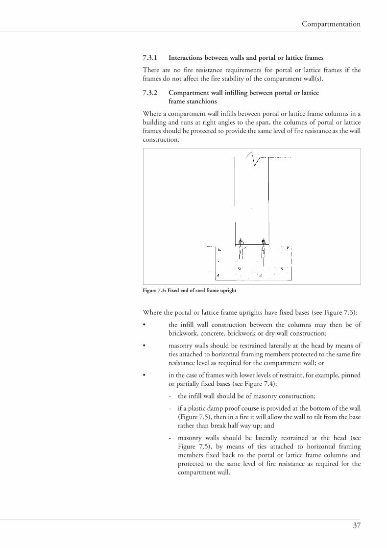
Compartmentation
37
7.3.1 Interactions between walls and portal or lattice frames
There are no fire resistance requirements for portal or lattice frames if theframes do not affect the fire stability of the compartment wall(s).
7.3.2 Compartment wall infilling between portal or lattice frame stanchions
Where a compartment wall infills between portal or lattice frame columns in abuilding and runs at right angles to the span, the columns of portal or latticeframes should be protected to provide the same level of fire resistance as the wallconstruction.
Figure 7.3: Fixed end of steel frame upright
Where the portal or lattice frame uprights have fixed bases (see Figure 7.3):
• the infill wall construction between the columns may then be ofbrickwork, concrete, brickwork or dry wall construction;
• masonry walls should be restrained laterally at the head by means ofties attached to horizontal framing members protected to the same fireresistance level as required for the compartment wall; or
• in the case of frames with lower levels of restraint, for example, pinnedor partially fixed bases (see Figure 7.4):
- the infill wall should be of masonry construction;
- if a plastic damp proof course is provided at the bottom of the wall(Figure 7.5), then in a fire it will allow the wall to tilt from the baserather than break half way up; and
- masonry walls should be laterally restrained at the head (see Figure 7.5), by means of ties attached to horizontal framingmembers fixed back to the portal or lattice frame columns andprotected to the same level of fire resistance as required for thecompartment wall.
Compartmentation CORE 2 1/2/08 11:34 Page 37

FPA Design Guide: the Fire Protection of Buildings
38
Figure 7.4: Details of portal frame base connections, pinned and ‘partially’ fixed
Figure 7.5a: Method of restraining masonry wall
Figure 7.5b: Compartment wall supported by portal frame and adjacent steelwork
Adjacent steelwork
Compartment wall supported portal frame
Adjacent steelwork
Compartmentation CORE 2 1/2/08 11:34 Page 38

Compartmentation
39
7.3.3 Compartment walls running parallel to portal or lattice frames
If compartment walls run parallel to the span of a portal or lattice frame:
• where a compartment wall is built up to the underside of a portal orlattice frame, such framing should have the same level of fire resistanceas that required for the compartment wall;
• at the wall/roof junction fire-stopping should be applied if necessaryto maintain the continuity of fire resistance;
• portal or lattice frames on each side of the wall – together with theconnecting lateral beams and any secondary roof supporting structurewhich is important to the stability of the wall spanning between thoseportal or lattice frames – should be protected to the same level of fireresistance as the compartment wall (see Figure 7.5b above) (steelsections having an Hp/A ratio greater than 260m-1 may not be able tobe economically protected to the same standard); or
• the compartment wall should be designed to have sufficientloadbearing capacity in order to resist any overturning momentapplied by the roof construction if fire causes the portal or latticeframes on one side to collapse; or
• a section should be designed into the roof construction or supportingmembers, adjacent to the point where the roof spans or bears on thecompartment wall, which has adequate strength in the cold state, butwhich is weaker in the ‘hot’ state so that collapse of the roof on thefire side minimises the potential for failure of the compartment wall.A possible method is illustrated in Figure 7.6 below.
Figure 7.6: Example of hot-state collapse mechanism
Fire resistant panel
Portal rafter
Noggins / bridging panelsJoint / break off point
Mineral wool 'cockscomb'
Mineral wool gasket
Compartment wall
Intumescent mastic seal
Purlin fixing bolt / fulcrumCleatPurlin
Continuous butt joint on centreline of roof (to allow for break-off in the event of fire) sealed over with roof membrane
Roof membrane on insulation on vapour barrier on steel decking
Movement gap between purlinsSteel channels fixed between purlins
Slot in cleat to allow collapse
Compartmentation CORE 2 1/2/08 11:34 Page 39

FPA Design Guide: the Fire Protection of Buildings
40
7.3.4 Comb connections
This is a connection design, which transmits only minor reaction forces to thefire wall in case of failure of the connected unprotected beam. This type ofconnection is characterised by open slotted holes. The open slotted holes enablethe failing beam to slide out of the connection without damaging the fire wall.To avoid thermally induced restraining forces, the slots are elongated, enablingthermal elongation of the connected beam during the heating process (seeFigure 7.7).
Figure 7.7: Comb connections
The torsional loadbearing capacity of comb connections is not sufficient toprovide torsional support. As a result, the lateral torsional buckling capacity ofthe beam is reduced significantly if no restraint of the rotation at the combconnections is provided.
7.3.5 Combination of pull-off connections and comb connections
Both design concepts can be combined (see Figure 7.8).
Figure 7.8: Combination of maximum tensile resistance of bolts and comb connection
This type of connection allows the beam to slide off the bracket for load casesinvolving movement which is perpendicular to the fire wall. For a load caseinvolving rotation a bending moment is activated, which is limited by themaximum tensional loadbearing capacity of the bolts.
a) b)
Compartmentation CORE 2 1/2/08 11:34 Page 40

Compartmentation
41
Section 8
MATERIALS AND THEIRBEHAVIOUR IN A FIRE
8.1 Robust materials
The following table gives some guidance on robust materials that could he usedfor compartment walls and floors to give sufficient resistance to impact andother mechanical damage, subject to them conforming to the relevant standardof fire resistance.
PRODUCT DESCRIPTION DIMENSIONS
Brick and blockwork Density not less than 600kg/m2 and not less than 100mm thick(subject to a slenderness ratio (thickness/height) not less than 0.025)
StudsTimber > 47mm x 89mm softwood > 400kg/m2
Steel > 50mm x 150mm mild steel channel or Z section – 1mm thick
JoistsTimber > 471mm x 225mm softwood > 400kg/m2
Steel > 70mm x 250mm mild steel – 1mm thick
Boards/liningsGypsum-basedPlasterboard 19mm thick as a single layerPlasterboard 12mm thick as part of a multiple layerReinforced plasterboard 15mm thick as a single layerReinforced plasterboard 10mm thick as part of a multiple layerGlass-reinforced Gypsum 12mm thick as a single layerGlass-reinforced Gypsum 9mm thick as part of a multiple layerCalcium silicate-basedFlexural strength (dry) 5-7.5 (N/mm2) 15mm as a single layerFlexural strength (dry) 5-7.5 (N/mm2) 10mm as part of a multi-layer systemFlexural strength (dry) Above 7.5 (N/mm2) 12mm as a single layerFlexural strength (dry) Above 7.5 (N/mm2) 9mm as part of a multi-layer system
Composite boardsGypsum-based chipboard 15mm as a single layerGypsum-based chipboard 10mm as part of a multi-layer systemCement-based chipboard 12mm as a single layer
Fire-resisting glazingWired glass (fire and safety) 6mmLaminated fire-resisting glass 12mm thick or greaterSolid fire-resisting monolithic glasses 10mm thick or greater
Glazing installed behind permanent screen protection (See Approved Document N, Building Regulations 2000)
Metal-faced insulated panels Steel faced mineral wool panels. Density of mineral wool not less than100kg/m3 and a minimum thickness of 100mm
Thickness of steel not less than 0.7mm
Compartmentation CORE 2 1/2/08 11:34 Page 41
FPA Design Guide: the Fire Protection of Buildings
42
8.2 Passive fire protection products and installation standards
All passive fire protection products falling within the scope of this documentshall be subject to certain measures relating to their specification andinstallation, since they are the subject of a number of the Design guide’s essentialprinciples, in particular:
• building materials should be used which will not make a significantcontribution to a fire at any stage of its growth (Principle 2);
• a building’s structure should be designed to have resistance to collapseor excessive deflection in the event of a fire (Principle 3); and
• the building should be constructed in such a way as to minimise theextent of fire and smoke damage in the event of fire (Principle 10).
These are supported by two other principles:
• only third-party certificated fire protection products should bespecified (Principle 5); and
• competent, specialist installers should be commissioned to fit fireprotection products/systems (Principle 6). (Installers shall be third-party certified to install the specific product/system when anappropriate scheme is available – for example, FIRAS or LPCB).
Even the best and safest of designs will be undermined if inappropriate or substandard products are used; or if the products and systems are properly specified but the standard of installation and workmanship isinadequate or unsupervised.
The Design guide’s associated construction design and product performancedata sheets – which give generic information about the performance of types ofpassive fire protection products and systems – are available via the FPA website:www.thefpa.co.uk/Resources/Design+Guide.
Some trade associations publish advice about such products and installationstandards and reference could be made to documents produced by the PassiveFire Protection Federation, the Association for Specialist Fire Protection andthe Steel Construction Institute, as well as those of other organisations whichare listed in the references.
It is important that the designer has confidence in products which are specifiedfor the building under design and it is also vital that the standard of installationmatches the quality and purpose of the products.
Compartmentation CORE 2 1/2/08 11:34 Page 42

Compartmentation
43
GLOSSARY OF TERMS
The following explanations apply to terms used in this publication.
Assessment
An opinion of the likely performance of a component or element of structureif it were to be subjected to a standard fire resistance test. (See PFPF Guide toundertaking assessments in lieu of fire tests.)
Building services
Services supplied or collected by pipes, ducts and cables, such as water, gas andelectricity, air conditioning, heating, communications, drains etc.
Cavity barrier
A fire-resisting barrier, not less than 100mm high, installed in a ceiling or floorvoid or roof space, that is able to provide the required fire resistance (and other)requirements of this guidance, as appropriate. (For the purposes of this Designguide, cavity barriers are not permitted above compartment walls.)
Compartment floor
A horizontal, fire-resisting floor designed to contain fire within an area for apredetermined duration in order to minimise the risk of fire spread.
Compartment wall
A loadbearing or non-loadbearing vertical fire-resisting wall designed to containa fire within an area for a predetermined duration in order to minimise the riskof fire spread. (Insurers formerly referred to a compartment wall of 240minutes’ fire resistance as a fire-break wall.)
Compartmentation
The division of a building into fire-resisting compartments, comprising one ormore rooms, spaces or storeys, by elements of construction designed to containa fire for a predetermined duration.
Competent contractor
An installation company which is approved/certificated under a recognisedthird-party installer scheme.
Cotton pad criterion
During testing described in the BS 476-20 series, one measure involves the useof cotton wool pads which are placed in the vicinity of the non-fire side of theproduct or joint which is being tested. The time taken for ignition of the padmay contribute to determining whether or not the product/joint passes the test.
Doorset
A complete, factory-produced door unit, comprising the frame, the door leaf itself, architrave and hardware. A door frame may or may not include astop, but it should not be seen as a separate component. In the UK, many doorsare now double swing and do not have a stop. Consequently, they rely oncorrectly set door closers to maintain the doors in a closed position whenexposed to a fire.
Compartmentation CORE 2 1/2/08 11:34 Page 43

FPA Design Guide: the Fire Protection of Buildings
44
Double door (doors in tandem)
In the context of this design guidance, this refers to the use of two or more doorassemblies in series – that is, in tandem – in order to provide increased fireresistance with respect to one or more criteria (for example, reduction inradiation if uninsulated).
Elements of construction
This term covers: structural framework, walls (internal and external), floors,roofs, stairs and enclosures to floor openings.
In this design guidance it is given a slightly broader meaning than in someofficial guidance. It includes, for example, the roof of a building, a feature notcovered by the definition of the similar term ‘element of construction’ inApproved Document B to the Building Regulations.
Direct field of application
Rules in a published standard that allow for slight changes to the testedproduct without the need to apply an expert judgement. Simple assessmentscan be assumed to fit within this definition.
Evidence of performance
Evidence in the form of a result of an appropriate fire test, performed in alaboratory approved by the United Kingdom Accreditation Scheme (UKAS),for carrying out the test, or from an assessment by a suitably qualified andcompetent body that demonstrates that the construction satisfies the relevantcriteria and, in the case of a fire-resisting element, maintains performance for asuitable duration.
Extended field of application
An expert technical evaluation of the likely performance of an element ofstructure if it were subjected to a standard fire resistance test. Such anassessment would be undertaken using the appropriate CEN EXAP standardand established engineering principles. Complex assessments can be assumed tofit within this definition.
Fire-break wall
A term formerly used by insurers to describe an imperforate compartment wallwith at least 240 minutes’ fire resistance, used to separate different occupancieswithin a building or to separate two buildings. Note: no fire resistance levelabove 240 minutes is recognised within the European classification system.
Fire engineered solution
A design in which the performance of the building or its elements ofconstruction has been established in a quantitative way which takes intoaccount all relevant factors and is in accordance with proven or publishedmethodology (see BS 7974-0).
Fire engineering
See Fire safety engineering.
Fire hazard
A source or situation which has the potential to cause a fire.
Fire integrity
See Integrity.
Compartmentation CORE 2 1/2/08 11:34 Page 44

Compartmentation
45
Fire load
Fire load is the sum of the individual calorific values of the materials used inthe construction of the building and of the building contents.
Fire resistance
Often cited in terms of a length of time, fire resistance is the ability of abuilding material or an element of construction, in a fire:
• to continue to bear a certain load for that length of time withoutfailure or deflection;
• to prevent fire passing from one compartment to another for thatduration; or
• both of the above.
Various test criteria exist under the different parts of BS 476 in relation to thefire resistances of different building materials/elements for varying applications.
Fire-resisting doorset or shutter assembly
A doorset or shutter assembly, of any design and construction which, whentested to methods 6, 7 or 8 given in BS 476-22: 1987 or when tested to BS EN1634-1, provides the specified level of fire resistance and any otherrequirements of this section of the Design guide, as appropriate to its design anduse. The doorset or shutter may be insulated or uninsulated.
Fire-resisting duct
A duct used for the distribution of air that, when tested to BS 476-24: 1987(ISO 6944: 1985) or BS EN 1366-1, provides the required fire resistance andother requirements of this design guidance. Note: BS EN 1366-1 is technicallya better standard than BS 476-24.
Fire risk
The product of the probability of fire occurring and the magnitude of theconsequences of that fire.
Fire safety engineering
The application of scientific and engineering concepts to the design andconstruction of a building so that the building will satisfy the fire safetydemands placed on it in relation to its size, layout, use and location.
Fire-stopping
A seal designed and tested to make good any imperfections in fit such that therequired fire resistance of the wall or floor, in terms of integrity, and insulationif appropriate, is maintained.
Flexural element
A beam or loadbearing floor that is subjected primarily to bending stresses.
Hp/A ratio
This is the ratio used to express the rate at which steel members absorb heatfrom their environment, expressed in ‘per metre’ units. It is the ratio of theheated perimeter, Hp, to the area of cross-section, A, of the steel member. Steelhollow sections with a low Hp/A ratio respond more slowly to heat and so havea longer duration of fire resistance.
Compartmentation CORE 2 1/2/08 11:34 Page 45

FPA Design Guide: the Fire Protection of Buildings
46
Height of building
This depends on the type of building and the roof configuration. For guidance,see Diagram C3 of Appendix C to Approved Document B to the BuildingRegulations (accessible via www.communities.gov.uk and follow links to‘Building Regulations – Documents and publications’).
Insulated door
Insulated doors can typically be either of timber construction, generally up to60 minutes’ fire resistance, or of a timber-faced, and possibly lipped, mineral-cored and/or framed construction, or be of an insulated steel-faced flush dooror a metal-framed stile and rail construction incorporating insulating glass. Theperformance of an insulated door is evaluated via the procedures of clause 6 ofBS 476-22 or BS EN 1634-1.
Insulation
The ability of an element of construction to restrict the transfer of heat fromthe fire side to the non-fire side of the element (BS 476-20 or BS EN 1363-1).
Integrity
The ability of an element of construction to restrict the spread of fire, smokeand combustion gases from the fire side to the non-fire side of the element (BS476-20 or BS EN 1363-1).
Masonry
Masonry elements are constructed from bricks or blocks made from fired clay,concrete with class 1 or class 2 aggregates or aerated concretes with densitiesbetween 480 and 1800kg/m2.
Material of limited combustibility
For the purposes of this Design guide, a material of limited combustibility is:
• any non-combustible material;
• any material of density 300kg/m2 or more which, when tested to BS 476-11, does not flame and for which the rise in temperature onthe furnace thermocouple is not more than 20°C;
• any material with a non-combustible core at least 8mm thick havingcombustible facings (on one or both sides) not more than 0.5mmthick (where a flame spread rating is specified, these materials shouldalso meet the appropriate test requirements); and
• any material of density less than 300kg/m2 which, when tested to BS 476-11, does not flame for more than 10 seconds and for which therise in temperature on the centre (specimen) thermocouple is not morethan 35°C and on the furnace thermocouple is not more than 25°C.
Non-combustible
A material may be considered to be non-combustible if it satisfies the requirements for non-combustibility when tested in accordance with BS 476-4 and 11 – that is, it does not flame and there is no rise intemperature on certain specified test thermocouples.
Occupancy
In this guidance, occupancy refers to a building or buildings which areoccupied by the same company irrespective of the purpose group or groupswhich may be involved.
Compartmentation CORE 2 1/2/08 11:34 Page 46

Compartmentation
47
Occupancy type
See Purpose group.
Penetration seal
A system for sealing any void in a compartment wall or floor through whichbuilding services pass which, when tested to EN 1366-3, provides the integrityand insulation requirement specified in this design guidance.
Purpose group
In this guidance, purpose group refers to the principal purpose of and activitywithin a building or part of a building, and also to adjoining building(s). Mayalso be known as occupancy type.
Occupancy
A building or part of a building in one ownership or tenancy.
Qualitative design review
A process which establishes the fire safety objectives for a building underdesign, as part of a fire safety engineering analysis, and is normally carried outin a multi-disciplinary team.
Relevant boundary
A boundary is a boundary of relevance to an external wall of a building if itcoincides with that external wall, is parallel to it or is at an angle of no morethan 80° to that side of the building.
Self-closing device
A device or mechanism, attached to or part of a fire-resisting doorset or shutterassembly, which provides a return to the closed position. Rising butt hinges arenot permitted.
Smoke-resistant lobby
An enclosure built around an opening in a compartment wall or floor,incorporating smoke control doors, which has been constructed to prevent theflow of smoke from one compartment to another.
Structural frame
The structural frame of a building comprises the elements of constructionrequired to support the dead load of the building itself and the imposed designloads associated with the building’s use. The structural frame may thereforeinclude columns, beams, floors and walls.
Third-party certification body
In the UK, the national accreditation body is the United KingdomAccreditation Service (UKAS); the Loss Prevention Certification Board(LPCB) is an example of a third-party certification body.
Uninsulated door
An uninsulated door does not possess the ability to restrict the rise oftemperature on the non-fire side of the door which, would result in fire beingtransmitted only when integrity fails. That is, it does not restrict the passage ofconducted and radiated heat in the manner of an insulated door.
Compartmentation CORE 2 1/2/08 11:34 Page 47

FPA Design Guide: the Fire Protection of Buildings
48
REFERENCESBritish and European standards
BS 476: Fire tests on building materials and structures
Part 4: 1970 Non-combustibility test for materials
Part 7: 1997 Method of test to determine the classification ofthe surface spread of flame of products
Part 11: 1982 Method for assessing the heat emission frombuilding materials
Part 21: 1987 Methods for determination of the fire resistanceof loadbearing elements of construction
Part 22: 1987 Methods for determination of the fire resistanceof non-loadbearing elements of construction
Part 23: 1987 Methods for determination of the contribution ofcomponents to the fire resistance of a structure
Part 24: 1987 Method for determination of the fire resistance ofISO 6944: 1985 ventilation ducts
Part 31.1: 1983 Methods for measuring smoke penetrationthrough doorsets and shutter assemblies. Methodof measurement under ambient temperatureconditions
BS EN 1363 Part 1: 1999 Fire resistance tests. General requirements
BS EN 1364 Part 1: 1999 Fire resistance tests for non-loadbearing elements. Walls
BS EN 1365 Fire resistance tests for loadbearing elements
Part 1: 1999 Walls
Part 2: 2000 Floors and roofs
Part 3: 2000 Beams
Part 4: 1999 Columns
BS EN 1366 Fire resistance tests for service installations
Part 1: 1999 Ducts
Part 2: 1999 Fire resisting dampers
Part 3: 2004 Penetration seals
Part 4: 2006 Linear gap seals
Part 5; 2003 Service ducts and shafts
Part 7: 2004 Conveyor systems and their closures
BS EN 1634 Fire resistance tests for door and shutter assemblies
Part 1: 2000 Fire doors and shutters
Part 3: 2004 Smoke control doors and shutters
BS 5234 Part l: 1992 Partitions (including matching linings). Code ofpractice for design and installation
Compartmentation CORE 2 1/2/08 11:34 Page 48

Compartmentation
49
BS 5268 Structural use of timber
Part 4.1: 1978 Recommendations for calculating fire resistance of timber members
Part 4.2: 1990 Fire resistance of timber structures.Recommendations for calculating fire resistance of timber stud walls and joisted floorconstructions
BS 5588 Part 12: 2004 Fire precautions in the design, construction anduse of buildings. Managing fire safety
BS 5628 Part 2: 2005 Code of practice for use of masonry. Structural use ofreinforced and pre-stressed masonry
BS 5950 Part 1: 2000 Structural use of steelwork in building. Code of practice for design. Rolled and welded sections
BS 7974: 2001 Application of fire safety engineering principles tothe design of buildings. Code of practice
BS 8110 Part 1: 1997 Structural use of concrete. Code of practice for designand construction
BS EN 12845: 2004 Fixed firefighting systems. Automatic sprinklersystems. Design, installation and maintenance
BS EN 13501 Fire classification of construction products andbuilding elements
Part 1: 2002 Classification using test data from reaction to fire tests
Part 2: 2003 Classification using data from fire resistance tests,excluding ventilation services
Part 3: 2005 Classification using data from fire resistance tests,fire resisting ducts and fire dampers
Fire Protection Association publications
Fire risk management in the workplace, 3rd edition, Adair Lewis and WilliamDailey, 2006.
FPA Design guide: Protection of openings and service penetrations from fire, 2005.
FPA Design guide: Protected zone, 2004.
FPA Design guide: Food processing factories, Part 1. Design principles, 2004.
LPC Rules for automatic sprinkler installations, incorporating BS EN 12845, 2003.
Loss Prevention Certification Board publications
List of approved fire and security products and services (annual).
Loss Prevention Standards
LPS 1158, issue 2: Requirements and tests for fire-resisting glazing systems.
LPS 1208 Issue 2:1 September 2005: LPCB Fire resistance requirements forelements of construction used to provide compartmentation.
Compartmentation CORE 2 1/2/08 11:34 Page 49

FPA Design Guide: the Fire Protection of Buildings
50
LPS 1181: Part 1: Issue 1.1: Series of fire growth tests for LPCB approval andlisting of construction product system: Requirements and tests for built-up claddingand sandwich panel systems for use as the external envelope of buildings.
LPS 1181: Part 2: Issue 2.0: Series of fire growth tests for LPCB approval andlisting of construction product systems: Requirements and tests for sandwich panelsand built-up systems for use as internal constructions in buildings.
LPS 1181: Part 4: Issue 1: Series of fire growth tests for LPCB approval and listingof construction product systems: Requirements and tests for external thermalinsulated cladding systems with rendered finishes (ETICS) or rain screen claddingsystems (RSC) applied to the face of a building.
LPS 1182: Issue 2: 1994: Requirements and tests for LPCB approval of fixedfabric smoke curtains, fixed metal smoke curtains and powered smoke curtains.
Official documents
The Building Regulations 2000, Approved Document B, Fire safety, Volume 2,Buildings other than Dwelling Houses (2006 edition).
The Building Regulations 2000, Approved Document N, Glazing – safety inrelation to impact opening and cleaning, 1998 (amended 2000).
Publications from trade associations and other groups
Ensuring best practice for passive fire protection in buildings, Association forSpecialist Fire Protection (ASFP), 2003.
Fire protection for structural steel in buildings, 4th edition, ASFP (with SteelConstruction Institute/Fire Test Study Group), 2007.
Fire and smoke resisting dampers, ASFP, 2007.
Fire resisting non-loadbearing partitions, ASFP, 2007.
Fire stopping and penetration seals for the construction industry, ASFP, 2007.
Fire resisting ductwork, ASFP, 2007.
Guide to demonstrating the performance of passive fire protection products, PassiveFire Protection Federation, 2004.
Guide to undertaking assessments in lieu of fire tests, Passive Fire ProtectionFederation, 2000.
Ensuring best practice for passive fire protection in buildings, Association forSpecialist Fire Protection, 2003.
A guide to best practice in the specification and use of fire-resistant glazed systems,Glass and Glazing Federation.
The IFSA code: Sealing apertures and service penetrations to maintain fireresistance, Intumescent Fire Seals Association.
GAI Code of practice, building hardware for fire-resisting doors and doorsets, Guildof Architectural Ironmongery and Door & Hardware Federation.
Code of practice for fire resisting metal doorsets, Door and Hardware Federation.
Best practice guide to timber fire doors, Architectural & Specialist DoorManufacturers Association, 2002.
Compartmentation CORE 2 1/2/08 11:34 Page 50

Compartmentation
51
Appendix A: Risk assessment: the principlesFar too often, industrial and commercial buildings are designed andconstructed with no considered thought given to an assessment of the hazards,including fire hazards, which may be introduced into the buildings by theiroccupiers. All too rarely do the designer, the occupier and the insurer manageto sit down together at an early stage to consider the matter, let alone carry outa risk assessment.
Risk assessment is, of course, an aspect of planning, and one which designersshould be able to take in their stride. The importance of carrying out such anassessment cannot be over emphasised, since the establishment of property
STAGE 1Identify all the fire hazards:(a) all possible sources of ignition,(b) combustible materials that: (i) are used or stored during business operations, (ii) are parts of furniture or furnishings, (iii) form parts of the structure or fittings,(c) flammable liquids and gases,(d) structural features that could lead to the spread of fire.
STAGE 2Identify people who could be at risk.
STAGE 3Eliminate, control or avoid the fire hazards.
STAGE 5Record the findings.
STAGE 6Prepare an emergency plan.
STAGE 7Carry out a periodic review of the assessment.
STAGE 4Consider whether the existing fire safety provisions are adequate or need improvement.
Figure A1: Seven-stage fire risk assessment
Compartmentation CORE 2 1/2/08 11:34 Page 51

FPA Design Guide: the Fire Protection of Buildings
52
protection objectives and criteria will enable the achievement of cost-effectivefire protection of the assets of the business. Designers should possess a broadview of how they may contribute to a risk assessment for property protectionpurposes.
It is necessary to acknowledge that, as mentioned above, a property protectionrisk assessment is more wide ranging than one carried out to establish the lifesafety and means of escape requirements to satisfy national legislation. Inaddition to the direct financial losses arising from a fire, the effect on theprofitability of the business needs to be assessed. (The FPA’s book, Fire riskmanagement in the workplace, is an excellent introduction to the topic.)
It follows, therefore, that higher standards of fire protection will often benecessary to achieve acceptable property protection criteria and objectives thanwould be required to satisfy national building regulations.
Methods for risk assessing specific categories of building are explained in sectorguides. Sector guides also contain tables describing the fire resistance standardof compartmentation in different situations.
Figure A1 outlines a method for the risk assessment of the acceptability ofcompartmentation in terms of its integration into the whole building.
Compartmentation CORE 2 1/2/08 11:34 Page 52
Compartmentation
53
Appendix B: The building as an entityB1. Assessing the effects of a fire on compartmentation
The following should be considered when carrying out an appraisal of thebehaviour of the structure under fire exposure:
• structural deflections are primarily thermally induced;
• changes in load do not significantly affect thermal deflections;
• deflections can cause significant problems when there is a need toensure compatibility of movement between adjacent members;
• deflections can cause adjacent non-heated members to be damaged orcollapse, and may cause gaps to occur between elements. These gapswill cause an integrity failure and assist in fire and smoke spread ifthey are not anticipated and accommodated at the design stage;
• unprotected steelwork, whether or not forming the structural framepart of a separating element, will deflect to a greater extent thanprotected steelwork;
• deflections should be designed out of the system by using suitablelevels of restraint so they do not occur; and
• if the previous point is not possible, then the magnitude of thedeflections should be calculated or estimated and then the structureshould be designed to accommodate these deflections.
These principles give the appraiser guidance on issues relating to maintenanceof compartmentation during a fire which need to be considered when assessingthe likely damage in a building. There are other issues, relating to theperformance of windows, ducts and other penetrations, and possible disruptionthereof as a result of thermally induced movement, which should also featurein the appraisal.
The behaviour and support requirements for such elements of construction arealso discussed in the appropriate places in the series of related date sheets whichare to be found on the design guide section of the FPA’s website,www.thefpa.co.uk/Resources/Design+Guide.
B2. The design process
The only way that the performance of a building in its entirety can beguaranteed is if each individual element is guaranteed to work in itsenvironment. To establish this, it is necessary to carry out a brief analysis ofeach element when considering its performance in the context of the elementsbounding it. This is achieved by considering each edge of a separating elementin turn to see if it can retain the fire integrity along that edge. In the case of anon-separating element, the behaviour at each end should be considered inturn to ensure that any movement does not reduce the integrity at or near thejunction, nor produce any significant change in the restraint conditions. Adecision tree approach, as given below, is recommended.
Compartmentation CORE 2 1/2/08 11:34 Page 53

FPA Design Guide: the Fire Protection of Buildings
54
Figure B1: To establish the acceptability of a compartment wall by reference to a decision tree(continued on following two pages)
B3. The decision tree approach
A decision tree has been established to assist in appraising the acceptability ofa compartment wall. The following comments relate to this decision tree(Figure B1):
• if it is possible to follow the flow diagram straight down the left-handside to the end point then the construction as tested is suitablewithout the need for any design or construction changes; and
• if the design needs to be changed, as a result of a ‘yes’ decision,indicating that the performance would be adversely affected by themovement, then the decision will need to be made either to preventthe deflection or to accommodate it.
Wall
Limit of safe storage zone
Floor below
Floor
Right handabutment
Left handabutment/support
Right handabutment/support
Front elevation of wall
Compartmentation CORE 2 1/2/08 11:34 Page 54

Compartmentation
55
Continued from page 54
Continued on page 56
Compartmentation CORE 2 1/2/08 11:34 Page 55

FPA Design Guide: the Fire Protection of Buildings
56
B4. Designing out the distortion
Should the appraisal indicate that the anticipated distortion cannot beaccommodated by either the elements bounding the wall or floor underconsideration, then the distortion should be restricted. There are a number ofways that this can be done dependent upon the practicality, cost or effectivenessof the various methods. A list of the possible options is given below:
• apply protection to the distorting element in excess of any protectionrequired for it to satisfy the fire resistance test (Note: according to BS476-21, the loadbearing capacity criteria for any element can besatisfied and yet it may still exhibit large resultant deflections. A floorwith a span of 4m is able to deflect 133mm and still comply with therequirements of the Standard. A non-loadbearing element has nolimit on its deflection as long as the distortion does not cause gaps todevelop within the structure of the element.);
• use a construction that has a greater cross-section than is needed tosatisfy the loadbearing or stability requirement for the element. Thiswill mean that the element will be subjected to lower stress levels andwill have a greater stiffness, remain cooler because of increasedthermal inertia and hence reduce its tendency to bow. In a situationwhere fire attack could be from either direction, this will, in practice,mean that extra thickness is required on both sides;
• increase the restraint on vertical elements either by:
• restraining it on the cool, protected side of the construction; or
• adding protection to adjacent elements on the hot face, including any
Continued from page 55
Compartmentation CORE 2 1/2/08 11:34 Page 56

Compartmentation
57
bracing, so that they may provide additional restraint of the deflectingelement;
• in the case of horizontal elements, additional protected supports maybe provided;
• when collapse is inevitable, the structural joints should be designed sothat the collapse takes place in a predicted manner, away from thecritical location, allowing the members or elements immediatelyadjacent to the wall or floor to remain plane. An example is shown inFigure 7.8 and described in the accompanying text.
The analysis and the subsequent selection of a suitable system for controllingthe deflection may well require input from a suitably qualified fire safetyengineer or a structural engineer fully conversant with the fire engineeredconstruction.
B5. Accommodating the distortion
Should the appraisal indicate that the distortion cannot be prevented bydesign, it is important that the structure can accommodate the anticipateddistortion. It may be possible to incorporate this into the basic design. Forexample, where two adjacent elements are predicted to bow, then the size of thegap can be restricted if – in the case of two dissimilar elements – the stiffer ofthe two passes over the end of the less stiff element, rather than the other wayround. Frequently, the gap will need to be sealed with a linear gap sealingsystem that is able to meet both the cold performance requirements andmaintain the fire and smoke resistance in the ‘hot’ condition.
B6. Selecting a joint sealing system
Where the thermal distortion cannot be prevented by restraint, then the sealingsystem between the elements should be able to accommodate the maximumpredicted deflection resulting from non-sympathetic distortions.
In the case of a joint between two vertical elements, the gap will probablyincrease as the fire duration increases. With the joint between a vertical elementand a horizontal element where a seal is put in place to accommodate thevertical movement of the floor, the gap will reduce as the fire durationincreases. At this maximum gap width, the flexible seal is required to maintainthe integrity, with respect to the cotton pad criterion of BS 476-20: 1987, andinsulation of the compartment for the designated durations, see 1.1. Generally,the seal will need to become more effective as the environment heats up, ratherthan less effective. This would tend to indicate that intumescent sealingsystems are better than inert seals, especially where the gap is opening up.
Where sealing the gap between elements which separate different occupancies,the seal should also resist the spread of both hot and cold smoke. It is unlikelythat a mineral fibre seal, which will lose its binder during the heating process,will have the necessary impermeability to restrict the flow of smoke unless it issubsequently coated with a high-temperature sealing material. Where there isanticipated movement between the elements in normal service, the seal chosenshould be capable of accommodating that service movement.
Where the materials are different in nature – for example, timber and concrete– the seal should be supported by evidence of performance, or a field ofapplication, that covers the following:
Compartmentation CORE 2 1/2/08 11:34 Page 57

FPA Design Guide: the Fire Protection of Buildings
58
• duration of fire resistance;
• the maximum anticipated gap width; and
• the materials forming the gap.
The design of a detail capable of accommodating the deflection will depend onthe system being installed and will therefore be particular to the element beingappraised. The detail should be capable of tolerating the deflection without apremature reduction in the insulation or integrity at the joint. The systemdetail should be assessed by a suitably qualified fire safety engineer to sanctionits choice if the application is not covered by the direct field of application forthe seal.
If fire stopping is to be used and is to be located between walls (or walls andfloors) of different material types, then the fire-stopping material should havebeen tested with the different material types being used as the substrate.Further information on the selection of fire-stopping and/or linear gap-sealingsystems and materials is given in section 14 of the FPA Design guide: Protectionof openings and service penetrations from fire.
Compartmentation CORE 2 1/2/08 11:34 Page 58

Compartmentation
59
INDEXactive fire protection ............................................................ 24, 30adjacent premises.......................................................................... 34adjoining premises ............................................................ 6, 17, 47air distribution systems .......................................................... 9, 23Approved Document B ............................................ 26, 44, 46, 50Approved Document N ........................................................ 41, 50arson ............................................................................................ 6automatic fire alarm system .......................................................... 6
brick and blockwork ...................................................... 37, 41, 44business continuity see business interruptionbuilding collapse ............ 6, 15, 28, 29, 30, 33, 36, 39, 42, 53, 57Building Regulations .................... 5, 7, 26, 31, 41, 44, 46, 50, 52building services .................................................................... 43, 47business interruption .............................. 10, 13, 14, 17, 27, 30, 52
cables ........................................................................ 19, 23, 24, 43car parks ........................................................................................ 7cavity barriers ............................................................ 8, 16, 32, 43ceilings .......................................................... 9, 13, 22, 30, 31, 43comb connections ...................................................................... 40commercial premises ...................................................... 5, 6, 8, 51compartment floors see floorscompartment walls see wallscomposite panels .......................................................................... 8conveyors .................................................................. 19, 23, 24, 48core documents .......................................................... 5, 6, 7, 8, 10
dampers ............................................................................ 9, 48-50data sheets ........................................................................ 8, 15, 42deflection ............ 6, 12, 13, 17, 30, 31, 33, 34, 35, 42, 45, 53-58design principles ................................................................ 7, 12, 49differential movements ..................................................................35door closer .................................................................................. 43door hardware ...................................................................... 43, 50doors ........................................ 7, 9, 10, 15, 16, 21-24, 27, 43-50ducts ................................ 9, 13, 16, 19, 23-25, 43, 45, 48-50, 54dwelling houses ...................................................................... 7, 50
elements of construction .... 10, 15-19, 9-35, 43-50, 53, 56, 57, 59escalator ...................................................................................... 24essential principles ...................................................... 5, 6, 7, 8, 42evacuation .................................................................................. 10external walls see walls
FPA Design guide for the fire protection of buildings ........5-8, 10, 11,16,17, 21-24, 28, 33, 35, 42, 43, 45, 46, 49, 58
fascia boards ................................................................................ 32firefighting water .......................................................................... 6fire-stopping ........................................ 6, 9, 12, 13, 31, 39, 45, 58fire doors/shutters ............................................ 7, 9, 22, 24, 48, 50fire integrity ................ 7-9, 12, 13, 15, 17, 19, 21-24, 26, 30, 31,
33, 35, 44-47, 53, 57, 58 fire prevention ........................................................................ 6, 15fire protection/detection systems ........................ 6, 8, 9, 15, 30, 42
fire risk assessment .................. 7, 12-14, 17, 21, 22, 24, 30, 51-52fire safety engineering ........................................ 34, 44, 45, 47, 49fire safety management .................................................................. 6fire spread .......................... 8, 9, 12, 13, 15-17, 19, 26-28, 30, 43fire tests .................................................................... 43, 44, 48-50floors ..................7, 9, 11-13, 15, 17, 19-20, 21-24, 26, 27, 33-36,
42, 43, 44, 45, 47-49, 56-58fuel burning appliance .................................................................. 6
glass and glazing .......................... 9, 10, 15, 16, 23, 24, 41, 46, 50
hazardous substances/goods ........................................................ 14
industrial premises .......................................................... 5, 6, 8, 51infill wall .................................................................................... 37InFiReS ........................................................................................ 5installers ............................................................................ 6, 42, 43insulation ........................9, 15, 17, 19, 21, 23, 24, 26, 30, 31, 32,
33, 39, 45-47, 57, 58insurers .............................................. 7, 11, 13-15, 17, 43, 44, 51Insurers’ Fire Research Strategy Funding Scheme see InFiReS
joists ............................................................................................ 41
lattice frame .................................................................... 31, 37, 39legislation .................................................................................... 53life safety ...................................................................... 5, 7, 10, 53lifts/lift shaft ................................................................................ 19linings .................................................................................. 41, 49loadbearing elements .............................. 17, 33-35, 43, 48, 50, 56lobby .............................................................................. 22, 24, 47
maisonettes .................................................................................... 7means of escape .................................................... 7, 10, 21, 31, 53multi-storey buildings ........................................ 11-14, 27, 28, 33
occupancies ...................................... 10-15, 19-21, 42, 46, 47, 57offices .................................................................................... 10, 17openings .......... 7-10, 16-19, 21-25, 27, 29, 30, 35, 44, 47, 49, 58
partitions see wallspassive fire protection .......................................... 8, 15, 30, 42, 50penetrations ................ 7, 9, 12, 13, 16, 17, 19, 21-25, 30, 31, 35,
47-50, 53, 58seals .............................................................. 16, 24, 25, 47, 48, 50portal frame ........................................................ 28, 29, 31, 36, 38protected zone .................................................. 8-11, 13, 14, 26-32Protection of openings and service penetrations from fire ..............7, 16,
21-24, 35, 49pull-off connections .................................................................... 40purpose groups ........................................ 7, 10, 13-15, 19, 46, 47
QDR see qualitative design reviewqualitative design review ...................................................... 34, 47
Compartmentation CORE 2 1/2/08 11:34 Page 59

FPA Design Guide: the Fire Protection of Buildings
60
reaction in the event of fire ..........................................................6response to fire .............................................................................. 6risk assessment see fire risk assessmentroofs .................... 7, 8, 11, 16, 17, 22, 27, 28, 30, 31, 32, 36, 37,
9, 43, 44, 46, 48
seals see penetrationsself-closing device ........................................................................ 47service penetrations see penetrationsshafts .................................................................. 11, 19, 20, 24, 48shops .......................................................................................... 10shutters see fire doorssmoke ...................... 6, 9, 10, 12-17, 19, 21-24, 42, 46-50, 53, 57soffit boards .................................................................... 31, 32, 35sprinklers .............................................. 13, 21, 22, 26, 27, 30, 49stairway enclosures/stairwells ............................................ 7, 19, 44stand-alone car parks .................................................................... 7storage warehouse ........................................................................ 10structural frame .................... 8, 26, 29, 31, 33, 34, 36, 44, 47, 53studs .................................................................................... 41, 49third-party certification .............................................. 8, 15, 21, 47
UKAS ............................................................................ 15, 44, 47unexposed face ...................................................................... 12, 16uninsulated door .................................................................. 21, 47United Kingdom Accreditation Service see UKAS
valuable materials ........................................................................ 10ventilation ................................................................ 31, 32, 48, 49voids .................................................................................... 43, 47walls
compartment ........................ 7-12, 14-18, 21-23, 26-31, 33-39,41, 43, 44, 47, 54
external ................................................ 9, 19, 26-28, 31, 32, 47fire break .................................................................... 17, 43, 44partitions ...................................................................... 9, 49, 50internal ........................................................................ 9, 44, 50warehouse see storage warehouseworkmanship ...................................................................... 6, 42
Compartmentation CORE 2 1/2/08 11:34 Page 60

Compartmentation
61
Compartmentation CORE 2 1/2/08 11:34 Page 61

for the FireProtection ofBuildings
CORE DOCUMENT
COMPARTMENTATION
Compartmentation CORE 2 1/2/08 11:35 Page 62