bdp-10a/16a/21l hydrostatic pumps service and repair manual
TRANSCRIPT

We set the wheels in motion.�
BDP-10A/16A/21L Hydrostatic Pumps
Service and Repair Manual BLN-51337
Revision August 2003

Table of Contents
Section PageForeword.............................................................................................................................. i
Description and Operation ................................................................................................ 1Introduction .................................................................................................................................................. 1General Description ..................................................................................................................................... 1External Features BDP-10A......................................................................................................................... 2External Features BDP-16A......................................................................................................................... 3External Features BDP-21L ......................................................................................................................... 4Hydraulic Schematic BDP-10A/16A ............................................................................................................. 5Hydraulic Schematic BDP-21L..................................................................................................................... 6Graphical Schematic BDP-10A/16A/21L ...................................................................................................... 7Technical Specifications BDP-10A/16A/21L ................................................................................................. 8Product Identification ................................................................................................................................... 8
Safety .................................................................................................................................. 9Personal Safety ........................................................................................................................................... 9Tool Safety ................................................................................................................................................... 9Work Area Safety ........................................................................................................................................ 9Servicing Safety ........................................................................................................................................... 9
Troubleshooting ............................................................................................................... 10BDP Flow Test Kit Instructions ............................................................................................................. 11,12
Service and Maintenance ................................................................................................ 13External Maintenance ................................................................................................................................ 13Service and Maintenance Procedures ........................................................................................................ 13Fluids ........................................................................................................................................................ 13Fluid Volume and Level .............................................................................................................................. 14Fluid Change ............................................................................................................................................. 14Filters ........................................................................................................................................................ 14Purging Procedures ................................................................................................................................... 14
Repair ................................................................................................................................ 15Tools and Torques ................................................................................................................................. 15,16Input Shaft Seal BDP-10A/16A/21L ............................................................................................................ 17Trunnion Arm Seal BDP-10A/16A/21L ........................................................................................................ 18Check Valves BDP-10A/16A/21L ............................................................................................................... 19System Check Reliefs or Shock Valves BDP10A/16A/21L ......................................................................... 20Bypass BDP-10A/16A/21L ........................................................................................................................ 21Charge Pump BDP-10A/16A/21L .......................................................................................................... 22,23End Cap and Valve Plate BDP-10A/16A/21L ......................................................................................... 24-26Cylinder Block BDP-10A/16A/21L ......................................................................................................... 27,28Block Spring, Thrust Washer and Thrust Bearing BDP-10A/16A/21L.......................................................... 29Swashplate and Cradle Bearings BDP-10A/16A/21L ................................................................................. 30Input Shaft BDP-10A/16A/21L ............................................................................................................... 31,32Trunnion Arm BDP-10A/16A/21L ................................................................................................................ 33
Notes ................................................................................................................................. 34
Parts List ...................................................................................................................... 35-40
Glossary of Terms ....................................................................................................... 41-42

BDP-10A/16A/21L i
FOREWORDHeadquartered in Sullivan, Illinois, Hydro-Gear isa world leader in the design, manufacture, andservice of quality hydrostatic transaxles for thelawn and garden industry. The mission of ourcompany is to be recognized by our customersand the industry as a world-class supplier and thequality leader in everything we do.
This Service and Repair Manual is designed toprovide information useful in servicing theHydro-Gear 10cc Bantam Duty Pump (BDP-10A), 16cc Bantam Duty Pump (BDP-16A) and21cc Bantam Duty Pump (BDP-21L).
Also included is a glossary of terms that arefrequently used throughout the industry and inHydro-Gear service publications. Understand-ing terminology is very important!
It is necessary, and good shop practice, that yourservice area be equipped with proper tools and
the mechanics to be supplied with the latestinformation available. All repair procedures illus-trated in this guide are suggested, butpreferred methods of repair.
Some repair procedures require that the BDP beremoved from the vehicle.
This is not a certification, test or study guide for acertification test. If a technician is interested incertification they should contact an agentrepresenting the ESA (Engine ServiceAssociation) (610) 363-3844 or their Hydro-GearDistributor. Many distributors will be hostingcertification testing. These study guides will covermost of the products and manufacturers in ourindustry.
For more information about Hydro-Gear or ourproducts, please contact your Central ServiceDistributor, or call our Customer Service Depart-ment at (217) 728-2581.

1 BDP-10A/16A/21L
A fixed displacement gerotor charge pump is pro-vided in the BDP units. Oil from the external res-ervoir and filter is pumped into the closed loop bya charge pump. Fluid not required to replenishthe closed loop flows either into the pump hous-ing through a cooling orifice, or back to the chargepump inlet through the charge pressure reliefvalve.
Check valves are included in the pump end capto control the makeup oil flow for the system. Thesize and type of check valve can play an impor-tant role on the system pressure, response, andamount of heat generated, due to the recircula-tion of makeup oil flow. Additionally, some BDP�smay be equipped with System Check Reliefs(SCR�s). SCR�s are factory preset pressure regu-lating check valves.
In some applications of the BDP�s, it is desirableto move the machine for short distances at lowspeeds without operating the engine. An increasein resistance will occur with movement at higherspeeds. A screw type bypass valve is utilized inthe pumps to permit movement of the machine.The bypass valve is fully opened when unscrewedtwo (2) turns maximum. The bypass valve allowsoil to be routed from one side of the pump/motorcircuit to the other, thus allowing the motor to turnwith minimal resistance. The bypass valve mustbe fully closed during normal operation.
WARNINGActuating the bypass will result in the lossof hydrostatic braking capacity. The ma-chine must be stationary on a level sur-face and in neutral when actuating thebypass.
Additionally, some BDP�s may be equipped withan Auxiliary Pump. The Auxiliary incorporatesthe principles of the charge gerotor assembly andprovides the capability of an external auxiliary flowfor an alternate hydraulic circuit to operate ac-cessories without loss of drive.
INTRODUCTIONThe purpose of this manual is to provide infor-mation useful in servicing the Hydro-Gear Ban-tam Duty Pumps (BDP�s). This manual includesthe BDP�s general descriptions, hydraulic sche-matics, technical specifications, servicing andtroubleshooting procedures for BDP models10A, 16A and 21L.
The BDP�s normally will not require servicing dur-ing the life of the vehicle in which it is installed.Should other servicing be required, the exteriorof the BDP�s will need to be thoroughly cleanedbefore beginning most procedures.
The models BDP -10A, 16A and 21L differ fromthe BDP model 10L. The physical distinction inappearance of the BDP-10A, 16A and 21L issignified by the design of an aluminum end cap.This end cap improves versatility in the applica-tion of these products.
GENERAL DESCRIPTIONThe BDP�s can be combined with wheel motorsand other remotely located units. These pumpsprovide an infinitely variable speed range be-tween zero and full displacement in both forwardand reverse modes of operation.
The BDP-10A, 16A and 21L are of the axial pis-ton design, utilizing spherical nosed pistons. Acompression spring, located inside each piston,holds the nose of the piston against a thrust bear-ing race.
The variable displacement pump features acradle swashplate with a direct-proportional dis-placement control. Reversing the direction ofthe angle of the swashplate reverses the flow ofoil from the pump and thus reverses the direc-tion of motor output rotation.
Movement of the directional control shaft pro-duces a proportional swashplate movement anda change in pump flow and/or direction.
SECTION 1. DESCRIPTION AND OPERATION

2 BDP-10A/16A/21L
"A" and "B" PORTS
DIAGNOSTIC PORT
SAE "A" PAD FLANGE STYLE
STANDARD CHECK VALVE OR SCR
CASE DRAIN OPTION BYPASS VALVE
CHARGE COVER
STANDARD CHECK VALVE OR SCR TRUNNION ARM
CASE DRAIN OPTION
INLET INPUT SHAFT
Figure 1. BDP-10A With Standard Charge Pump
EXTERNAL FEATURES BDP-10A
TRUNNION ARM
CHARGEPRESSURE
STANDARD CHECK VALVEOR SHOCK VALVE
STANDARD CHECK VALVEOR SHOCK VALVE

3 BDP-10A/16A/21L
EXTERNAL FEATURES BDP-16A
Figure 2. BDP-16A With Standard Charge Pump
TRUNNION ARM
INPUT SHAFT
CHARGE PRESSUREDIAGNOSTIC PORT
�A� and �B� PORTS
INLET
BYPASS VALVECASE DRAIN
CHARGECOVER CASE DRAIN
SYSTEM CHECK VALVEOR SHOCK VALVE
SYSTEM CHECK VALVEOR SHOCK VALVE
SAE �A� PADFLANGE STYLE
BYPASSVALVE

4 BDP-10A/16A/21L
TRUNNION ARM
SAE "B" PAD FLANGE STYLE
CASE DRAIN
DIAGNOSTIC PORT
STANDARD CHECK VALVE OR SCR
CHARGE COVER
BYPASS VALVE
INLET
"A" and "B" PORTSINPUT SHAFT
STANDARD CHECK VALVE OR SCR
Figure 3. BDP-21L With Standard Charge Pump
EXTERNAL FEATURES BDP-21L
CHARGEPRESSURE
STANDARD CHECK VALVEOR SHOCK VALVE
STANDARD CHECK VALVEOR SHOCK VALVE

5 BDP-10A/16A/21L
HYDRAULIC SCHEMATIC
Figure 4. BDP-10A/16A With Standard Charge Pump Hydraulic Schematic
PORT A
PORT B
CHARGE DIAGNOSTICCHARGE PUMP INLET
BYPASS VALVE BLEED OPTIONS: 1) NO BLEED ORIFICE
2) .031� BLEED ORIFICE3) .043� BLEED ORIFICE (BDP-10A/16A)
SYSTEM CHECK & RELIEF VALVE OPTIONS:1) NO SCR, NO BLEED2) NO SCR, .024� BLEED3) NO SCR, .031� BLEED4) NO SCR, .044� BLEED5) 3000 PSI SCR, NO BLEED (BDP-10A/16A) 3000 PSI SHOCK, NO BLEED (BDP-10A/16A)6) 3000 PSI SHOCK, .024� BLEED (BDP-10A/16A)7) 3000 PSI SCR, .031� BLEED (BDP-10A/16A) 3000 PSI SHOCK, .031� BLEED (BDP-10A/16A)8) 3000 PSI SHOCK, .044� BLEED (BDP-10A/16A)
Figure 5. BDP-10A/16A With Auxiliary Charge Pump Hydraulic Schematic
AUXILIARY DISCHARGE
AUXILIARY RETURN
CHARGE PUMP INLETCHARGE DIAGNOSTIC
PORT B
PORT A
SYSTEM CHECK & RELIEF VALVE OPTIONS:1) NO SCR, NO BLEED2) NO SCR, .024� BLEED3) NO SCR, .031� BLEED4) NO SCR, .044� BLEED5) 3000 PSI SCR, NO BLEED (BDP-10A/16A) 3000 PSI SHOCK, NO BLEED (BDP-10A/16A)6) 3000 PSI SHOCK, .024� BLEED (BDP-10A/16A)7) 3000 PSI SCR, .031� BLEED (BDP-10A/16A) 3000 PSI SHOCK, .031� BLEED (BDP-10A/16A)8) 3000 PSI SHOCK, .044� BLEED (BDP-10A/16A)
BYPASS VALVE BLEED OPTIONS: 1) NO BLEED ORIFICE
2) .031� BLEED ORIFICE3) .043� BLEED ORIFICE (BDP-10A/16A)

6 BDP-10A/16A/21L
HYDRAULIC SCHEMATIC
Figure 6. BDP-21L With Standard Charge Pump Hydraulic Schematic
Figure 7. BDP-21L With Auxiliary Charge Pump Hydraulic Schematic
3) .043� BLEED ORIFICE
3) .043� BLEED ORIFICE
SCR, NO BLEED ORIFICE6) SCR, .031� BLEED ORIFICE7) SHOCK, NO BLEED ORIFICE8) SHOCK, .024� BLEED ORIFICE9) SHOCK, .031� BLEED ORIFICE10) SHOCK, .044� BLEED ORIFICE
SCR, NO BLEED ORIFICE6) SCR, .031� BLEED ORIFICE7) SHOCK, NO BLEED ORIFICE8) SHOCK, .024� BLEED ORIFICE
9) SHOCK, .031� BLEED ORIFICE10) SHOCK, .044� BLEED ORIFICE

7 BDP-10A/16A/21L
Figures 4-7 represent hydraulic schematics ofthe standard charge and auxiliary charge pump.Figure 8 provides a graphical illustration of thehydraulic oil circuit.
The input shaft and pump cylinder block are turnedin one direction only by the engine/ drive belt/pulley combination or direct drive gear box.
The oil is drawn through an external filter that pre-vents contaminants within the reservoir from en-tering into the charge pump gerotor.
The charge pump supplies fluid to keep theclosed loop pressurized, preventing cavitationand providing cooling oil flow for the system.
The charge relief valve is used to maintain chargeat a predetermined pressure.
Output of the system oil flow is controlled by thedirection and amount that the swashplate isangled. As the pump pistons compress, theyforce oil into one of two passageways (�A� or �B�)in the system hydraulic circuit. Oil is supplied ex-
ternally under pressure to an external load, (e.g.,a vehicle wheel motor). As the angle of the pumpswashplate is increased, the amount of oil beingpumped will increase and cause a higher speedoutput of the wheel motor. Reversing the angleof the swashplate will reverse the direction of theoil flow. During the operation of the pump, fluidis �lost� from the hydraulic loop through leak pathsdesigned into the product for lubrication purposes(around pistons, under the rotating cylinderblock, etc.). This �lost� fluid returns to the reser-voir through the case drain. This fluid must bemade up in the loop. The charge pump makesup this fluid loss.
The makeup flow is controlled (or directed) bythe system check valves. The check valves areused to direct makeup fluid into the low pressureside of the closed loop. Each check valve willeither be held open or closed, depending uponthe direction of the vehicle operation: Closed ina pressurized system passage, open in a lowpressure, �charged� system passage.
Figure 8. BDP-10A,16A and 21L Standard Charge Pump Graphical Schematic
GRAPHICAL SCHEMATIC
8 BDP-10A/16A/21L
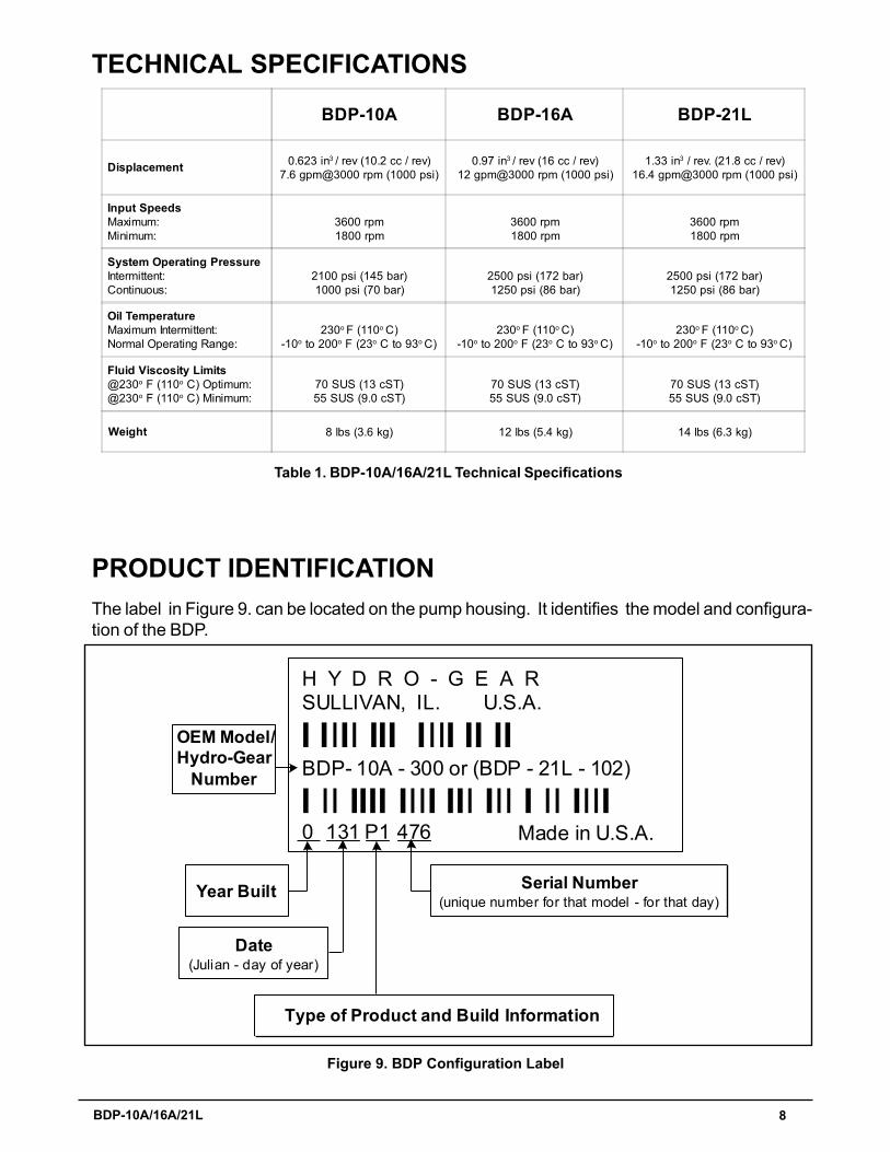
TECHNICAL SPECIFICATIONS
Table 1. BDP-10A/16A/21L Technical Specifications
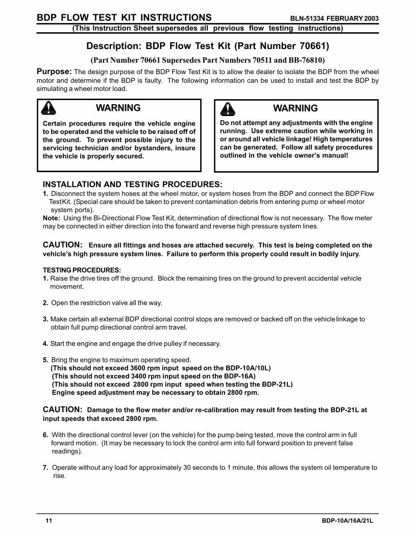
Figure 9. BDP Configuration Label
PRODUCT IDENTIFICATIONThe label in Figure 9. can be located on the pump housing. It identifies the model and configura-tion of the BDP.
0
H Y D R O - G E A RSULLIVAN, IL. U.S.A.
I IIII III IIII II IIBDP- 10A - 300 or (BDP - 21L - 102)
I II IIII IIII III III I II IIII131 P1 476 Made in U.S.A.
Year Built
Date(Julian - day of year)
Type of Product and Build Information
Serial Number(unique number for that model - for that day)
OEM Model/Hydro-Gear
Number
BDP-10A BDP-16A BDP-21L
Displacement 0.623 in3 / rev (10.2 cc / rev)7.6 gpm@3000 rpm (1000 psi)
0.97 in3 / rev (16 cc / rev)12 gpm@3000 rpm (1000 psi)
1.33 in3 / rev. (21.8 cc / rev)16.4 gpm@3000 rpm (1000 psi)
Input SpeedsMaximum:Minimum:
3600 rpm1800 rpm
3600 rpm1800 rpm
3600 rpm1800 rpm
System Operating PressureIntermittent:Continuous:
2100 psi (145 bar)1000 psi (70 bar)
2500 psi (172 bar)1250 psi (86 bar)
2500 psi (172 bar)1250 psi (86 bar)
Oil TemperatureMaximum Intermittent:Normal Operating Range:
230o F (110o C)-10o to 200o F (23o C to 93o C)
230o F (110o C)-10o to 200o F (23o C to 93o C)
230o F (110o C)-10o to 200o F (23o C to 93o C)
Fluid Viscosity Limits@230o F (110o C) Optimum:@230o F (110o C) Minimum:
70 SUS (13 cST)55 SUS (9.0 cST)
70 SUS (13 cST)55 SUS (9.0 cST)
70 SUS (13 cST)55 SUS (9.0 cST)
Weight 8 lbs (3.6 kg) 12 lbs (5.4 kg) 14 lbs (6.3 kg)

9 BDP-10A/16A/21L
This symbol points out important safetyinstructions which, if not followed, could endan-ger the personal safety and/or property of your-self and others. Read and follow all instructionsin this manual before attempting maintenanceon your BDP�s. When you see this symbol -HEED ITS WARNING.
WARNING
POTENTIAL FOR SERIOUS INJURY
Inattention to proper safety, operation, ormaintenance procedures could result inpersonal injury, or damage to the equip-ment. Before servicing or repairing theBDP-10A, 16A or 21L, fully read and un-derstand the safety precautions de-scribed in this section.
PERSONAL SAFETY
Certain safety precautions must be observedwhile servicing or repairing the BDP-10A, 16Aor 21L. This section addresses some of theseprecautions but must not be considered an all-inclusive source on safety information. This sec-tion is to be used in conjunction with all othersafety material which may apply, such as:
Other manuals pertaining to this machine Local and shop safety rules and codes Governmental safety laws and regulations
Be sure that you know and understand the equip-ment and the hazards associated with it. Do notplace speed above safety.
Notify your supervisor whenever you feel there isany hazard involving the equipment or the per-formance of your job.
Never allow untrained or unauthorized person-nel to service or repair the equipment.
TOOL SAFETYUse the proper tools and equipment for the task.
Inspect each tool before use and replace any toolthat may be damaged or defective.
WORK AREA SAFETY
Keep the work area neat and orderly. Be sure itis well lit, that extra tools are put away, trash andrefuse are in the proper containers, and dirt ordebris have been removed from the working ar-eas of the machine.
The floor should be clean and dry, and all exten-sion cords or similar trip hazards should be re-moved.
SERVICING SAFETY
Certain procedures may require the vehicle tobe disabled in order to prevent possible injuryto the servicing technician and/or bystanders.
The loss of hydrostatic drive line power may re-sult in the loss of hydrostatic braking capability.
Some cleaning solvents are flammable. Use onlyapproved cleaning materials: Do not use explo-sive or flammable liquids to clean the equipment.
To avoid possible fire, do not use cleaning sol-vents in an area where a source of ignition maybe present.
Discard used cleaning material in the appropri-ate containers.
Wear appropriate clothing. Loose or hangingclothing or jewelry can be hazardous. Use theappropriate safety equipment, such as eye andhearing protection, and safety-toe and slip-proofshoes.
Never use compressed air to clean debris fromyourself or your clothing.
SECTION 2. SAFETY

10 BDP-10A/16A/21L
WARNINGDo not attempt any servicing or adjust-ments with the engine running.Use extreme caution while inspecting thedrive belt assembly and all vehicle link-age!
Follow all safety procedures outlined inthe vehicle owner�s manual!
SECTION 3. TROUBLESHOOTING
In many cases problems with the BDP-10A, 16Aand 21L are not related to a defective pump butare caused by slipping drive belts, partially en-gaged bypass valves, and loose or damagedcontrol linkages. Be sure to perform all opera-tional checks and adjustments outlined in Sec-tion 3. before assuming the pump is malfunction-ing. Table 2. below provides a troubleshootingcheck list to help determine the cause of opera-tional problems.
Table 2. BDP 10A, 16A and 21L Troubleshooting Checklist
Possible Cause Corrective Action
VEHICLE DOES NOT DRIVE/TRACK STRAIGHT
UNIT IS NOISY
UNIT HAS NO/ LOW POWER
UNIT OPERATING HOT
BDP LEAKS OIL
Vehicle tires improperly inflated Refer to vehicle manufacturer suggested pressure Control linkage bent, loose or out of adjustment Repair, adjust or replace vehicle linkage Bypass loose Tighten bypass per page 11 Inlet leak Check all externals to BDP inlet
Excessive input speed Adjust input speed above 1800 rpm and below 3600 rpm Oil level low or contaminated oil Fill to proper level or change oil Excessive loading Reduce vehicle load Air trapped in hydraulic system Purge hydraulic system per page 12 Bypass loose Tighten bypass per page 11 Inlet leak, line or filter partially blocked or damaged Check all externals to BDP inlet
Engine speed low Adjust to correct setting Control linkage bent, loose or out of adjustment Repair or replace vehicle linkage Drive belt slipping or pulley damaged Repair or replace drive belt or pulley Oil level low or contaminated oil Fill to proper level or change oil per page 11 Excessive loading Reduce vehicle load Bypass loose Tighten bypass per page 11 Air trapped in hydraulic system Purge hydraulic system per page 12 Inlet leak Check all externals to BDP inlet Inlet filter clogged Replace filter per page 12 Suspected internal damage Check per page 9
Debris buildup Remove debris Cooling fan or heat exchanger damaged Repair or replace cooling fan or heat exchanger Oil level low or contaminated oil Fill to proper level or change oil per page 11 Excessive loading Reduce vehicle load Air trapped in hydraulic system Purge hydraulic system per page 12 Inlet leak Check all externals to BDP inlet
Damaged seals or gaskets Remove debris, replace seals Air trapped in hydraulic system Purge hydraulic system per page 12
11 BDP-10A/16A/21L
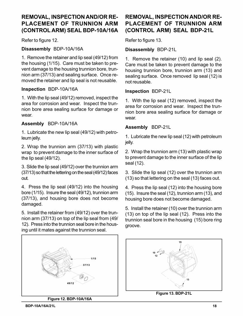
BDP FLOW TEST KIT INSTRUCTIONS BLN-51334 FEBRUARY 2003(This Instruction Sheet supersedes all previous flow testing instructions)
Description: BDP Flow Test Kit (Part Number 70661)(Part Number 70661 Supersedes Part Numbers 70511 and BB-76810)
Purpose: The design purpose of the BDP Flow Test Kit is to allow the dealer to isolate the BDP from the wheelmotor and determine if the BDP is faulty. The following information can be used to install and test the BDP bysimulating a wheel motor load.
Certain procedures require the vehicle engineto be operated and the vehicle to be raised off ofthe ground. To prevent possible injury to theservicing technician and/or bystanders, insurethe vehicle is properly secured.
WARNINGDo not attempt any adjustments with the enginerunning. Use extreme caution while working inor around all vehicle linkage! High temperaturescan be generated. Follow all safety proceduresoutlined in the vehicle owner�s manual!
WARNING
INSTALLATION AND TESTING PROCEDURES:1. Disconnect the system hoses at the wheel motor, or system hoses from the BDP and connect the BDP Flow Test Kit. (Special care should be taken to prevent contamination debris from entering pump or wheel motor system ports).Note: Using the Bi-Directional Flow Test Kit, determination of directional flow is not necessary. The flow metermay be connected in either direction into the forward and reverse high pressure system lines.
CAUTION: Ensure all fittings and hoses are attached securely. This test is being completed on thevehicle�s high pressure system lines. Failure to perform this properly could result in bodily injury.
TESTING PROCEDURES:1. Raise the drive tires off the ground. Block the remaining tires on the ground to prevent accidental vehicle movement.
2. Open the restriction valve all the way.
3. Make certain all external BDP directional control stops are removed or backed off on the vehicle linkage to obtain full pump directional control arm travel.
4. Start the engine and engage the drive pulley if necessary.
5. Bring the engine to maximum operating speed. (This should not exceed 3600 rpm input speed on the BDP-10A/10L)
(This should not exceed 3400 rpm input speed on the BDP-16A)(This should not exceed 2800 rpm input speed when testing the BDP-21L)Engine speed adjustment may be necessary to obtain 2800 rpm.
CAUTION: Damage to the flow meter and/or re-calibration may result from testing the BDP-21L atinput speeds that exceed 2800 rpm.
6. With the directional control lever (on the vehicle) for the pump being tested, move the control arm in full forward motion. (It may be necessary to lock the control arm into full forward position to prevent false readings).
7. Operate without any load for approximately 30 seconds to 1 minute, this allows the system oil temperature to rise.

12 BDP-10A/16A/21L
Note: Raising the system oil temperature will make a difference in the readings you receive. It has beendetermined that to complete this test accurately, the oil temperature must be near system operating temperatures.Suggested temperature range 160°- 210°F (71.1° - 98.9°C)
8. On the BDP-10A/10L, BDP-16A and BDP-21L tighten the restriction valve until you read 300 psi (21 bar). Record the flow reading from the Bi-Directional Flow Meter.
9. Increase the pressure to 1100 PSI (76 bar) for all models (BDP-10A/10L, BDP-16A and BDP -21L). Record the flow reading from the Bi-Directional Flow Meter.
10. The acceptable gpm �flow droop� or (difference) is:BDP-10A/10L 1.5 gpm (5.6 l/min)BDP-16A 2.0 gpm (7.6 l/min)BDP-21L 2.0 gpm (7.6 l/min)
If the difference exceeds these values the pump would not be acceptable.
TEST EXAMPLE: BDP-10A/10L
300 psi (21 bar) reading 7 gpm (26 l/min) (1st reading)
1100 psi (76 bar) reading 3 gpm (11 l/min) (2nd reading)
(BDP-10A/10L) 300 psi (21 bar) reading 7 gpm (26 l/min) (1st reading)1100 psi (76 bar) reading 3 gpm (11 l/min) (2nd reading)
4 gpm (15 l/min) (the difference)
Subtract the 1st reading from the 2nd.(In this example, 4 gpm difference wouldindicate a defective pump).
FROM WHEEL MOTOR
CONNECTIONS TOTHE FWD./RVS. LINESDISCONNECTED
BI-DIRECTIONALFLOWMETER
RESTRICTIONVALVE
FROM WHEEL MOTORDISCONNECTEDTHE FWD./RVS. LINESCONNECTIONS TO
FLOWMETERBI-DIRECTIONAL
VALVERESTRICTION

13 BDP-10A/16A/21L
8. Inspect the vehicle control linkage to the di-rectional control arm on the BDP. Also, in-sure the control arm is securely fastened tothe trunnion arm.
9. Inspect the bypass on the BDP to insure it isproperly engaged for operation. If the bypassis not fully engaged (rotated fully clockwise)it will not function properly. For vehicle move-ment, the bypass may be backed out (2) turnsmaximum. This is only recommended formovement of short distances at low speeds.
WARNINGLoosening the bypass will result in lossof hydraulic braking capability.
SERVICE AND MAINTENANCEPROCEDURES
NOTE: Damage to BDP�s may result fromexternal or internal contamination: Heatfrom excess debris or lack of lubricationand over-pressurization of the product.Follow guidelines established in thismanual and the vehicle manufacturer�srecommendations.
All the service procedures presented on the fol-lowing pages can be performed while the BDPis mounted on the vehicle. Any servicing beyondthose given must be performed after the unit hasbeen removed from the vehicle.
SECTION 4. SERVICE AND MAINTENANCE
NOTE: Any servicing dealer attemptinga warranty repair must have prior ap-proval before conducting maintenanceof a Hydro-Gear product unless the ser-vicing dealer is a current Authorized Hy-dro-Gear Service Center.
EXTERNAL MAINTENANCE
Regular external maintenance of the BDP shouldinclude the following:
1. Check the vehicle operator�s manual forthe recommended load ratings. Insurethe current application does not exceedload rating.
2. Check fluid level in reservoir in accordancewith vehicle manufacturer�s recommenda-tions.
NOTE: After oil has been drained andmaintenance has been performed, cleanoil should be poured directly into thepump inlet and high pressure ports priorto plumbing reconnection and start-up.
3. Inspect the vehicle drive belt, idler pulley(s),and idler spring(s). Insure that belt slippageis not causing low input rpm to the pump.
4. Inspect all external plumbing for possibleleaks or loose fittings. An air leak may bedifficult to detect on the �suction side� or inletline to the pump. See purging procedurespage 12.
5. Insure correct inlet filter(s) has been installedin accordance with the vehicle manufacturer.
6. Insure the reservoir is free of contaminantsand is properly vented.
7. Inspect the BDP cooling fan (if applicable)for broken or distorted blades and removeany obstructions (grass clippings, leaves ordirt). Inspect oil cooler (if applicable) for dam-aged fins and debris.
FLUIDSThe fluids used in Hydro-Gear products havebeen carefully selected, and only equivalent, orbetter products should be substituted.
Typically, an engine oil with a minimum rating of55 SUS (9.0 cSt) at 230° F (110° C) maximumoperating temperature and an API classificationof SJ/ CD is allowed. Refer to the vehicle manu-facturer for recommended oil.

14 BDP-10A/16A/21L
FLUID VOLUME AND LEVELCertain situations may require additional fluid tobe added or even replaced. Refer to the vehiclemanufacturer�s recommendations for the properfill location and level. After maintenance or oilchange, follow purging procedures below and re-check the fluid level once the unit has been oper-ated for approximately 1 minute.
FLUID CHANGE In the event of oil contamination or degradation,oil addition or change may alleviate certain per-formance problems. Refer to the vehiclemanufacturer�s recommended oil change fre-quency. Refer to purging procedures below.
FILTERSAn inlet filter is required to insure that only cleanfluid enters the system. Refer to the vehicle manu-facture for approved filter replacement.
The following procedures should be performedwith the vehicle drive wheels off the ground, thenrepeated under normal operating conditions.
WARNINGPOTENTIAL FOR SERIOUS INJURY
Certain procedures require the vehicleengine to be operated and the vehicle tobe raised off of the ground. To preventpossible injury to the servicing techni-cian and/or bystanders, insure the ve-hicle is properly secured.
1. With the bypass valve open and the enginerunning, slowly move the directional controlin both forward and reverse directions (5 to 6times), as air is purged from the unit, the oillevel will drop.
2. With the bypass valve closed and the enginerunning, slowly move the directional controlin both forward and reverse directions (5 to 6times). Check the oil level, and add oil as re-quired after stopping engine.
3. It may be necessary to repeat Steps 1 and 2until all the air is completely purged from thesystem. When the BDP�s move forward andreverse at normal speed purging is complete.
Cleanliness is a key factor in the successful re-pair of BDP�s. Thoroughly clean all exposedsurfaces prior to any type of maintenance. Clean-ing of all parts by using a solvent wash and airdrying is usually adequate. As with any preci-sion equipment, all parts must be kept free offoreign material and chemicals. Protect all ex-posed sealing areas and open cavities from dam-age and foreign material.
Upon removal, all seals, O-rings, and gasketsshould be replaced. During installation, lightlylubricate all seals, O-rings, gaskets with cleanpetroleum jelly prior to assembly. Also protectthe inner diameter of seals by covering the shaftmachined features with plastic wrap or equiva-lent.
PURGING PROCEDURESDue to the effects air has on efficiency in hydro-static drive applications, it is critical that air ispurged from the system.
These purge procedures should be imple-mented anytime a hydrostatic system has beenopened to facilitate maintenance or any addi-tional oil has been added to the system.
Air creates inefficiency because it has compres-sion and expansion rates that are higher thanthat of oil.
Entrained air in the oil may cause the followingsymptoms:
1. Noisy operation
2. Lack of power or drive after short-term op-eration
3. High operation temperature and excessiveexpansion of oil.
Before starting, make sure the reservoir is at theproper oil level. If it is not, fill to the vehiclemanufacturer�s specifications.

15 BDP-10A/16A/21L
SECTION 5. REPAIRHOW TO USE THIS MANUALEach assembly is provided with an explodedview showing the parts involved. The itemreference numbers in each illustration arefor assembly instructions only. See pages35-40 for part names and descriptions. Acomplete exploded view and item list of the pumpis provided at the end of this section.
GENERAL INSTRUCTIONSCleanliness is a primary means of assuringsatisfactory life on repaired pumps. Thoroughlyclean all exposed surfaces prior to any type ofmaintenance. Cleaning of all parts by using asolvent wash and air drying is usually adequate.As with any precision equipment, all parts mustbe kept free of foreign material and chemicals.
Protect all exposed sealing surfaces and opencavities from damage and foreign material. Theexternal surfaces should be cleaned beforebeginning any repairs.
Table 3. Required Tools
MiscellaneousBDP-10A/16A/21L Service & Repair ManualTorque WrenchScribe, Paint Pen, or MarkerSeal Hook with a MagnetFlat Blade Screw DriverPliersInternal Snap RingAllen Wrenches5 mm3/16�1/4�
Sockets3/8� Drive Ratchet9/16�1/2�5/8�10 mmCombination Wrenches9/16�1/2�5/8�7/8�10 mm
TOOLS AND TORQUES
Lip type seals (shaft seals) are used on the inputshaft and directional control shaft of theBDP-10A, 16A and 21L. These seals can bereplaced without major disassembly of the unit.However, replacement of these seals generallyrequires removal of the pump from the machine.Upon removal, it is recommended that all seals,O-rings and gaskets be replaced. Duringinstallation lightly lubricate all seals, O-rings andgaskets with a clean petroleum jelly prior toassembly. Also protect the inner diameter of theseals by covering the shaft with a cellophane(plastic wrap, etc.) material.
Parts requiring replacement must be replacedfrom the appropriate kits identified in the ItemsListing, found at the end of this manual. Use onlyoriginal Hydro-Gear replacement parts foundlisted in BLN-50937 (microfiche) or BLN-51427(CD).

16 BDP-10A/16A/21L
Table 4. BDP-10A Plug Fitting Torque Values
Table 6. BDP-21L Plug Fitting Torque Values
Item # or Description TorqueCase Drain (fitting torque) 200-250 lb-in (22.6-28.2 N-m)System Port (fitting torque) 370-470 lb-in (41.8-53.1 N-m)Inlet (fitting torque) 200-250 lb-in (22.6-28.2 N-m)42A, 42B, Check Valves/Shock Valves 180-240 lb-in (20.3-27.1 N-m)42A, 42B, Check Reliefs (cap) 200-275 lb-in (22.6-31.0 N-m)15, Bypass Valve 84-120 lb-in (9.5-13.6 N-m)56, Diagnostic Plug 84-120 lb-in (9.5-13.6 N-m)10, Cap Screw (non-auxiliary) 87-118 lb-in (9.8-13.3 N-m) 4, End Cap Bolts 167-217 lb-in (18.8-24.5 N-m)
Item # or Description TorqueCase Drain fitting (fitting torque) 370-470 lb-in (41.8-53.1 N-m)System Port (fitting torque) 370-470 lb-in (41.8-53.1 N-m)Inlet (fitting torque) 370-470 lb-in (41.8-53.1 N-m)42A, 42B, Check Valves/Shock Valves 180-240 lb-in (20.3-27.1 N-m)42A, 42B, Check Reliefs (cap) 200-275 lb-in (22.6-31.0 N-m)50, Bypass Valve 84-120 lb-in (9.5-13.6 N-m)52, Diagnostic Plug 84-120 lb-in (9.5-13.6 N-m)56, Charge Cover Cap Screw (non-auxiliary) 200-275 lb-in (22.6-31.0 N-m)58, End Cap Bolts 255-345 lb-in (28.8-38.9 N-m)
Table 5. BDP-16A Plug Fitting Torque Values
Item # or Description TorqueCase Drain (fitting torque) 200-250 lb-in (22.6-28.2 N-m)System Port (fitting torque) 370-470 lb-in (41.8-53.1 N-m)Inlet (fitting torque) 370-470 lb-in (41.8-53.1 N-m)42A, 42B Check Valves/Shock Valves 180-240 lb-in (20.3-27.1 N-m)42A, 42B Check Reliefs (cap) 200-275 lb-in (22.6-31.0 N-m)50, Bypass Valve 95-120 lb-in (10.7-13.6 N-m)52, Diagnostic Plug 85-120 lb-in (9.6-13.6 N-m)56, Charge Cover Cap Screw (non-auxiliary) 180-220 lb-in (20.3-24.9 N-m)58, End Cap Bolts 255-300 lb-in (28.8-33.9 N-m)

17 BDP-10A/16A/21L
15
1
5
6
4
3
Figure 11. BDP-16A/21L
REMOVAL, INSPECTION AND/OR RE-PLACEMENT OF INPUT SHAFTSEAL BDP-10ARefer to Figure 10.
Disassembly BDP-10A
1. Remove retaining ring (22) from housing.
2. Remove lip seal (20). Care must be taken toprevent damage to the housing bore, shaft seal-ing surface, or bearing. Once removed, the sealis not reusable.
Inspection BDP-10A
1. With seal removed inspect the spacer (21),input shaft bearing (19) and housing (1) bore fordamage, corrosion or wear.
Assembly BDP-10A
1. Lubricate the new lip seal (20) with petroleumjelly.
2. Wrap the input shaft (18) with plastic wrap toprevent damage to the inner surface of the lipseal (20).
3. Slide seal (20) over shaft (18) so that letter-ing on the seal faces out.
4. Press the lip seal (20) into the housing bore.Insure the lip seal (20), shaft (18) or housing (1)bore does not become damaged.
5. Install the retaining ring (22) into the housing(1) bore groove.
REMOVAL, INSPECTION AND/OR RE-PLACEMENT OF INPUT SHAFTSEAL BDP-16A/21L
Refer to Figure 11.
Disassembly BDP-16A/21L
1. Remove retaining ring (3) from housing (15).
2. Remove lip seal (6). Care must be taken toprevent damage to the housing bore, shaft, seal-ing surface, or bearing. Once removed the sealis not reusable.
Inspection BDP-16A/21L
1. With the lip seal (6) removed, inspect thespacer (4) the shaft bearing (5) and housing (15)bore.
Assembly BDP-16A/21L
1. Lubricate the new lip seal (6) with petroleumjelly.
2. Wrap the input shaft (1) with plastic wrap toprevent damage to the inner surface of the lipseal (6).
3. Slide the seal (6) over shaft (1) so that letter-ing on the seal (6) faces out.
4. Press the lip seal (6) into the housing (15)bore. Insure seal (6), shaft (1) or housing (15)bore does not become damaged.
5. Install the retaining ring (3) into the housing(15) bore groove.
18
19
2120
22
1
Figure 10. BDP-10A
18 BDP-10A/16A/21L
Figure 12. BDP-10A/16A
1/15
37/13
49/12
REMOVAL, INSPECTION AND/OR RE-PLACEMENT OF TRUNNION ARM(CONTROL ARM) SEAL BDP-21LRefer to figure 13.
Disassembly BDP-21L
1. Remove the retainer (10) and lip seal (2).Care must be taken to prevent damage to thehousing trunnion bore, trunnion arm (13) andsealing surface. Once removed lip seal (12) isnot reusable.
Inspection BDP-21L
1. With the lip seal (12) removed, inspect thearea for corrosion and wear. Inspect the trun-nion bore area sealing surface for damage orwear.
Assembly BDP-21L
1. Lubricate the new lip seal (12) with petroleumjelly.
2. Wrap the trunnion arm (13) with plastic wrapto prevent damage to the inner surface of the lipseal (12).
3. Slide the lip seal (12) over the trunnion arm(13) so that lettering on the seal (13) faces out.
4. Press the lip seal (12) into the housing bore(15). Insure the seal (12), trunnion arm (13), andhousing bore does not become damaged.
5. Install the retainer (10) over the trunnion arm(13) on top of the lip seal (12). Press into thetrunnion seal bore in the housing (15) bore ringgroove.
Figure 13. BDP-21L
15
12
13
10
REMOVAL, INSPECTION AND/OR RE-PLACEMENT OF TRUNNION ARM(CONTROL ARM) SEAL BDP-10A/16ARefer to figure 12.
Disassembly BDP-10A/16A
1. Remove the retainer and lip seal (49/12) fromthe housing (1/15). Care must be taken to pre-vent damage to the housing trunnion bore, trun-nion arm (37/13) and sealing surface. Once re-moved the retainer and lip seal is not reusable.
Inspection BDP-10A/16A
1. With the lip seal (49/12) removed, inspect thearea for corrosion and wear. Inspect the trun-nion bore area sealing surface for damage orwear.
Assembly BDP-10A/16A
1. Lubricate the new lip seal (49/12) with petro-leum jelly.
2. Wrap the trunnion arm (37/13) with plasticwrap to prevent damage to the inner surface ofthe lip seal (49/12).
3. Slide the lip seal (49/12) over the trunnion arm(37/13) so that the lettering on the seal (49/12) facesout.
4. Press the lip seal (49/12) into the housingbore (1/15). Insure the seal (49/12), trunnion arm(37/13), and housing bore does not becomedamaged.
5. Install the retainer from (49/12) over the trun-nion arm (37/13) on top of the lip seal from (49/12). Press into the trunnion seal bore in the hous-ing until it mates against the trunnion seal.

19 BDP-10A/16A/21L
42A(PORT "A" SIDE)
42B(PORT "B" SIDE)
2/25
Figure 14. BDP-10A/16A
REMOVAL, INSPECTION AND/OR RE-PLACEMENT OF CHECK VALVESBDP-10A/16ARefer to Figure 14.
Disassembly BDP-10A/16A
Perform disassembly, inspection and assemblyon check valves one side at a time. Some unitsvary in �A� side to �B� side check configuration.
1. Remove the check valve (42) with 1/4� allenwrench.
2. Remove the valve spring and poppet fromthe BDP end cap (2/25).
Inspection BDP-10A/16A
1. Inspect the poppets and mating seats in theend cap (2/25) for damage or foreign material.
Assembly BDP-10A/16A
1. Lay the BDP on its side, so the check plugport is horizontal.
2. Insert the check plug, spring and poppet (42)as one assembly into the check plug port.Tighten, reference Tables 4 & 5, page 16, fortorque values.
Repeat disassembly, inspection and assemblyfor the opposite port side.
REMOVAL, INSPECTION AND/OR RE-PLACEMENT OF CHECK VALVESBDP-21LRefer to Figure 15.
Disassembly BDP-21L
Perform disassembly, inspection and assemblyon check valves one side at a time. Some unitsvary in �A� side to �B� side check configuration.
1. Remove the check valve (42) with 1/4� allenwrench.
2. Remove the valve spring and poppet fromthe BDP end cap (25).
Inspection BDP-21L
1. Inspect the poppet and mating seats in theend cap (25) for damage or foreign material.
Assembly BDP-21L
1. Lay the BDP on its side, so the check plugport is horizontal.
2. Insert the check plug, spring and poppet (42)as one assembly into the check plug port.Tighten, reference Table 6, page 16, for torquevalues.
Repeat disassembly, inspection and assemblyfor the opposite port side.
Figure 15. BDP-21L
25
42B
42A

20 BDP-10A/16A/21L
Disassembly BDP-21L
Perform disassembly, inspection and assemblyon SCR/shock valve one side at a time. Someunits vary in �A� side to �B� side configuration.
1. Remove the SCR (42) with a 7/8� wrench orthe shock valve (42) with an 11/16� wrench.
2. Remove the check relief/shock valve springand the check relief/shock valve from the BDPend cap (25).
Inspection BDP-21L
1. Inspect the check relief or shock valve(42)and mating seat in the end cap (25) for damageor foreign material.
Assembly BDP-21L
1. Lay the BDP on its side, so the check plugport is horizontal.
2. Insert the system check relief spring andcheck relief or shock valve spring and shockvalve as one assembly into the check plug port.Tighten, reference Table 6, page 16, for torquevalues.
Repeat disassembly, inspection and assemblyfor the opposite port side.
REMOVAL, INSPECTION AND/OR RE-PLACEMENT OF SYSTEM CHECKRELIEFS (SCR�s) OR SHOCKVALVES BDP-10A/16ARefer to Figure 16.
Disassembly BDP-10A/16A
Perform disassembly, inspection and assemblyon SCR/shock valve one side at a time. Someunits vary in �A� side to �B� side configuration.
1. Remove the SCR (42) with a 7/8� wrench orthe shock valve (42) with an 11/16� wrench.
2. Remove the check relief/shock valve springand the check relief/shock valve from the BDPend cap (2/25).
Inspection BDP-10A/16A
1. Inspect the check relief or shock valve (42)and mating seat in the end cap (2/25) for dam-age or foreign material.
Assembly BDP-10A/16A
1. Lay the BDP on its side, so the check plugport is horizontal.
2. Insert the system check relief spring andcheck relief or shock valve spring and shockvalve as one assembly into the check plug port.Tighten to the correct torque value. See page 16.
Repeat disassembly, inspection and assemblyfor the opposite port side.
Figure 16. BDP-10A/16A Figure 17. BDP-21L
REMOVAL, INSPECTION AND/OR RE-PLACEMENT OF SYSTEM CHECKRELIEFS (SCR�s) OR SHOCKVALVES BDP-21LRefer to Figure 17.
42B
42A
2/25
42B
25
42A

21 BDP-10A/16A/21L
Inspection BDP-10A/16A
1. Inspect the bypass O-rings and mating seatsin the end cap (2/25) for damage or foreign mate-rial.
2. If damaged or worn replace bypass (15/50).
Assembly BDP-10A/16A
1. Lay the BDP on its side, so the bypass portis horizontal.
2. Insert the bypass (15/50) into the bypassport on the end cap (2/25). Tighten to the propertorque value. See page 16.
REMOVAL, INSPECTION AND/OR RE-PLACEMENT OF THE BYPASS BDP-21LRefer to Figure 19.
Disassembly BDP-21L
1. Loosen the bypass valve (50) using a 5/8�wrench.
2. Remove the bypass (50) from the BDP endcap (25).
Inspection BDP-21L
1. Inspect the bypass O-rings and mating seatsin the end cap (25) for damage or foreign mate-rial.
Figure 18. BDP-10A/16A
2/25
15/50
50
25
Figure 19. BDP-21L
2. If damaged or worn replace bypass (50).
Assembly BDP-21L
1. Lay the BDP on its side, so the bypass portis horizontal.
2. Insert the bypass (50) into the bypass porton the end cap (25). Tighten, reference Table 6,page 16, torque values.
REMOVAL, INSPECTION AND/OR RE-PLACEMENT OF THE BYPASS BDP-10A/16ARefer to Figure 18.
Disassembly BDP-10A/16A
1. Loosen the bypass valve (15/50) using a 5/8�wrench.
2. Remove the bypass (15/50) from the BDPend cap (2/25).

22 BDP-10A/16A/21L
10
6
18
44
2
Partial View
Figure 20. BDP-10A
Assembly BDP-10A
1. Lay the BDP (input shaft down), so the endcap (2) is horizontal. Place the charge ball (44)in the end cap (2) charge pocket so it mates tothe end cap (2) charge ball seat. Place thecharge spring, also identified as item (44), ontop of the charge ball.
2. Insert the inner gerotor over input shaft (18).
3. Align the outer gerotor to fit over the innergerotor.
4. Insert the O-ring into the charge cover.
5. Position the charge cover and O-ring with thealigning mark on the end cap. Place the chargecover and O-ring as one piece over the chargespring and gerotor assembly. Insure the springfits into the charge cover spring retaining groove.
6. Align and insert the allen screws (6) into theend cap (2). Tighten, reference Table 4, page16, torque values.
REMOVAL, INSPECTION ANDASSEMBLY OF THE STANDARDCHARGE PUMP BDP-10ARefer to Figure 20.
Disassembly BDP-10A
1. Prior to removal of the charge cover, place amark on the charge cover and end cap for re-alignment.
2. Using a 5 mm allen wrench, loosen the chargecover bolts (10) from the BDP end cap (2). Whileholding the charge cover in place, remove thecharge cover bolts (10).
3. Remove the charge cover, O-ring, gerotoritems (6), charge spring and charge ball (44).
Inspection BDP-10A
1. Inspect the charge cover O-ring and runningsurfaces for damage. Inspect the spring , checkball (44), and mating seat in the end cap (2) fordamage or foreign material.
Note: If end cap (2) is to be removed, de-lay charge components reassembly.

23 BDP-10A/16A/21L
25
58 x4
44
40
56 x2
1Partial View
Figure 21. BDP-16A/21L
Inspection BDP-16A/21L
1. Inspect the charge cover O-ring and runningsurfaces for damage. Inspect the spring , checkball (44), and mating seat in the end cap (25) fordamage or foreign material.
2. If damaged or worn, replace O-ring andgerotor assembly (40), charge spring and chargeball (44) and end cap (25).
Note: If end cap (25) is to be removed,delay charge components reassembly.
REMOVAL, INSPECTION AND AS-SEMBLY OF THE STANDARDCHARGE PUMP BDP-16A/21LRefer to Figure 21.
Disassembly BDP-16A/21L
1. Prior to removal of the charge cover, place amark on the charge cover and end cap for re-alignment.
2. Using a 1/2� wrench loosen the charge coverbolts from the BDP end cap (25). While holdingthe charge cover in place, remove the chargecover bolts (56).
3. Remove the charge cover, O-ring, gerotoritems (40), charge spring and charge ball (44).
Assembly BDP-16A/21L
1. Lay the BDP (input shaft down), so the endcap is horizontal. Place the charge ball in theend cap (25) charge pocket so it mates to theend cap (25) charge ball seat. Place the chargespring on top of the charge ball.
2. Insert the inner gerotor over input shaft (1).
3. Align the outer gerotor to fit over the innergerotor.
4. Insert the O-ring into the charge cover.
5. Position the charge cover and O-ring with thealigning mark on the end cap (25). Place thecharge cover and O-ring as one piece over thecharge spring and gerotor assembly. Insure thespring fits into the charge cover spring retaininggroove.
6. Align and insert the cap screws (56) into thecharge cover. While holding the charge cover inplace tighten the cap screws (56) per Tables 5and 6, page 16.
BDP-21L
44
4x 58
25
1
40
56
56
BDP-16A

24 BDP-10A/16A/21L
REMOVAL, INSPECTION AND AS-SEMBLY OF THE END CAP ANDVALVE PLATE BDP-10ARefer to Figure 22.
Disassembly BDP-10A
1. Using a 10 mm wrench, loosen the end capbolts (4) evenly.
2. Keeping the end cap (2) held in place, re-move the four end cap bolts (4).
3. Slowly remove the end cap (2).
4. Remove the valve plate (31).
5. Remove housing alignment pins (3).
6. Remove housing gasket (5).
Inspection BDP-10A
1. Inspect the end cap (2) body for damage,nicks or unusual wear patterns. Replace if nec-essary.
2. Inspect the running surface (side that con-tacts the cylinder block) of the valve plate (31).The running surface may show evidence ofminor abrasive rings.
This is normal. Grooving in the plate, or materialtransfer that is evident when the surface ischecked by dragging a fingernail across it, wouldbe cause for replacement of the valve plate.
3. Inspect and replace alignment pins (3) if bentor distorted.
4. Replace the housing gasket (5) with a newgasket before reassembly.
Assembly BDP-10A
1. Install housing gasket (5) into housing gasketseat in housing (1).
2. Install alignment pins (3) into housing (1).
3. Lubricate the valve plate prior to installation.Install valve plate (31) so the stamped letters �CL�on the valve plate are facing up toward theendcap.
4. Install end cap (2). Before installing the fourend cap bolts (4), push down on end cap (2)verifying alignment and insuring that the cylinderblock pistons spring back and forth. Install endcap bolts (4). Tighten, reference Table 4, page16, torque values.
5
31
1
3
6
10
4
2
44
Figure 22. BDP-10A

25 BDP-10A/16A/21L
REMOVAL, INSPECTION AND AS-SEMBLY OF THE END CAP ANDVALVE PLATE BDP-16ARefer to figure 23.
Disassembly BDP-16A
1. Using any combination of two, 9/16� wrenchesor 9/16� socket and rachet drive, loosen the endcap bolts (58) evenly.
2. Keeping the end cap (25) held in place re-move the four end cap bolts (58).
3. Slowly remove the end cap (25).
4. Remove the valve plate (29).
5. Remove housing alignment pins (26).
6. Remove housing gasket (28).
Inspection BDP-16A
1. Inspect the end cap (25) body for damage,nicks or unusual wear patterns. Replace if nec-essary.
2. Inspect the running surface (side that contactsthe cylinder block) of the valve plate (29). Therunning surface may show evidence of minorabrasive rings.
This is normal. Grooving in the plate, or materialtransfer that is evident when the surface ischecked by dragging a fingernail across it, wouldbe cause for replacement of the valve plate.
3. Inspect and replace alignment pins (26) if bentor distorted.
4. Replace the housing O-ring (28) with a newO-ring before reassembly.
Assembly BDP-16A
1. Install housing O-ring (28) into housing O-ringseat in housing (15).
2. Install alignment pins (26) into housing (15).
3. Lubricate the valve plate prior to installation.Install valve plate (29) so the stamped letters �UP�on the valve plate are facing up toward theendcap.
4. Install end cap (25). Before installing the fourend cap bolts (58), push down on end cap (25)verifying alignment and insuring that the cylinderblock pistons spring back and fourth. Install endcap bolts. Tighten, per Table 5, page 16, torquevalues.
Figure 23. BDP-16A
1526
26
2829
25
44
58 x4
40
56
56
26 BDP-10A/16A/21L
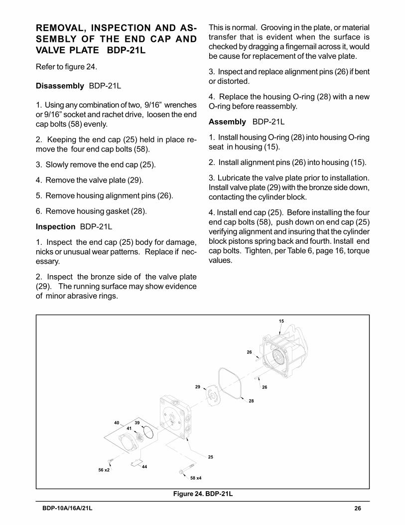
REMOVAL, INSPECTION AND AS-SEMBLY OF THE END CAP ANDVALVE PLATE BDP-21LRefer to figure 24.
Disassembly BDP-21L
1. Using any combination of two, 9/16� wrenchesor 9/16� socket and rachet drive, loosen the endcap bolts (58) evenly.
2. Keeping the end cap (25) held in place re-move the four end cap bolts (58).
3. Slowly remove the end cap (25).
4. Remove the valve plate (29).
5. Remove housing alignment pins (26).
6. Remove housing gasket (28).
Inspection BDP-21L
1. Inspect the end cap (25) body for damage,nicks or unusual wear patterns. Replace if nec-essary.
2. Inspect the bronze side of the valve plate(29). The running surface may show evidenceof minor abrasive rings.
This is normal. Grooving in the plate, or materialtransfer that is evident when the surface ischecked by dragging a fingernail across it, wouldbe cause for replacement of the valve plate.
3. Inspect and replace alignment pins (26) if bentor distorted.
4. Replace the housing O-ring (28) with a newO-ring before reassembly.
Assembly BDP-21L
1. Install housing O-ring (28) into housing O-ringseat in housing (15).
2. Install alignment pins (26) into housing (15).
3. Lubricate the valve plate prior to installation.Install valve plate (29) with the bronze side down,contacting the cylinder block.
4. Install end cap (25). Before installing the fourend cap bolts (58), push down on end cap (25)verifying alignment and insuring that the cylinderblock pistons spring back and fourth. Install endcap bolts. Tighten, per Table 6, page 16, torquevalues.
Figure 24. BDP-21L
4139
56 x244
58 x4
25
29
28
26
15
26
40

27 BDP-10A/16A/21L
REMOVAL, INSPECTION AND AS-SEMBLY OF THE CYLINDER BLOCKBDP-10ARefer to Figure 25.
Disassembly BDP-10A
1. Tilt the BDP on its side, drain remaining oil.Lift out the cylinder block assembly (25).
2. Remove the pistons, springs and piston seats.
Inspection BDP-10A
1. Inspect the running surface of the cylinderblock and piston ends for damage, nicks or un-usual wear patterns. The running surface mayshow evidence of minor abrasion . This will be anormal wear. If grooved or smeared, replace witha new cylinder block assembly.
2. Inspect the piston springs for distortion orbreakage. If necessary, replace with new cylin-der block kit.
3. Inspect the piston seats. Residual oil maycause these to remain stuck to the inside of thepistons.
25
Piston
PistonSeat
SpringCylinder Block
Figure 25. BDP-10A
NOTE: To check that piston placementis correct, push downward on the cylin-der block assembly (38). If this results ina spring action the block assembly hasbeen installed correctly. If this cannot beaccomplished, remove and reassemblethe block assembly. Place a rubber bandaround the cylinder block pistons to holdthem in position during installation. Thenafter installation cut the rubber band andremove it. Check for cylinder block as-sembly for spring action.
Assembly BDP-10A
1. Install piston seats into the end of the pistons.
2. Install springs into the pistons.
3. Install one at a time, pistons, springs and seatsas one assembly into the cylinder block.
4. With the BDP housing tilted on its side, installthe cylinder block assembly (25) with pistons con-tacting the thrust bearing.

28 BDP-10A/16A/21L
The running surface may show evidence of mi-nor abrasion . This will be normal wear. Ifgrooved or smeared, replace with a new cylin-der block assembly.
2. Inspect the piston springs for distortion orbreakage. If necessary, replace with new cylin-der block kit.
3. Inspect the piston seats. Residual oil maycause these to remain stuck to the inside of thepistons.
Assembly BDP-16A/21L
1. Install piston seats into the end of the pistons.
2. Install springs into the pistons.
3. Install one at a time, pistons, springs and seatsas one assembly into the cylinder block.
4. With the BDP housing tilted on its side, installthe cylinder block assembly (38) so that thepistons contact the thrust bearing.
NOTE: To check that piston placementis correct, push downward on the cylin-der block assembly (38). If this results ina spring action the block assembly hasbeen installed correctly. If this cannot beaccomplished, remove and reassemblethe block assembly. Place a rubber bandaround the cylinder block pistons to holdthem in position during installation. Thenafter installation cut the rubber band andremove it. Check for cylinder block as-sembly for spring action.
38
PistonSeat
Piston
Cylinder Block
Spring
Figure 26. BDP-16A/21L
REMOVAL, INSPECTION AND AS-SEMBLY OF THE CYLINDER BLOCKBDP-16A/21LRefer to Figure 26.
Disassembly BDP-16A/21L
1. Tilt the BDP on its side, drain remaining oil.Lift out the cylinder block assembly (38).
2. Remove the pistons, springs and piston seats.
Inspection BDP-16A/21L
1. Inspect the running surface of the cylinderblock and piston ends for damage, nicks or un-usual wear patterns.
(7x)
(7x)
(7x)

29 BDP-10A/16A/21L
REMOVAL, INSPECTION AND ASSEM-BLY OF BLOCKSPRING, THRUSTWASHER, AND THRUST BEARING,BDP-10A/16ARefer to Figure 27.
Disassembly BDP-10A/16A
1. Remove the block spring (29/20).
2. Remove the thrust washer (30/19).
3. Remove the thrust bearing and race (34/17).
Inspection BDP-10A/16A
1. Inspect and replace the block spring (29/20)and thrust washer (30/19) if they are distortedor broken.
2. Inspect the running surface of the bearingrace for damage, nicks or unusual wear patterns.The running surface may show evidence of mi-nor abrasion . This will be normal wear. Inspectthe bearings for free movement. Inspect thebearing cage for distortion or damage. Replaceif necessary.
Assembly BDP-10A/16A
1. Install thrust bearing and race assembly(34/17).
Figure 27. BDP-10A/16A
29/20
34/17
30/19
NOTE: The difference in race thickness:The thin race seats into the swashplate(32/31). The thicker race will be installedtoward the piston noses.
REMOVAL, INSPECTION AND AS-SEMBLY OF THRUST BEARING,BDP-21LRefer to Figure 28.
Disassembly BDP-21L
1. Remove the thrust bearing and race (17).
Inspection BDP-21L
1. Inspect the running surface of the bearingrace for damage (17), nicks or unusual wear pat-terns. The running surface may show evidenceof minor abrasion . This will be normal wear.Inspect the bearings for free movement. Inspectthe bearing cage for distortion or damage. Re-place if necessary.
Assembly BDP-21L
1. Install bearing and race assembly (17).
NOTE: The difference in race thickness:The thin race seats into the swashplate.The thicker race will be installed towardthe piston noses.
Figure 28. BDP-21L
17
2. Install thrust washer (30/19).
3. Install block spring (29/20).
30 BDP-10A/16A/21L
(Cradle Bearings cannot be removed from housing as depicted)
1314
3117 15
Disassembly BDP-21L
1. Remove the swashplate (31).
Inspection BDP-21L
1. Inspect the running surface of the bearingpocket for damage (31), nicks or unusual wearpatterns. The running surface may show evi-dence of minor abrasion . This will be normalwear. Inspect the cradle bearing side of theswashplate (31) damage. Replace if neces-sary.
2. Inspect the cradle bearings attached to theinside of housing (15) for normal wear patterns,placement, and insure they are staked in place.If damaged, replace housing (15).
Assembly BDP-21L
1. Install swashplate (31) by holding trunnionarm�s (13) slot guide (14) with the aide of a flattip screwdriver. Use the screwdriver to hold theslot guide (14) in place while positioning theswash plate (31) onto the cradle bearing in thehousing (15).
2. Rotate trunnion arm (13) to assure swashplatepivoting action.
NOTE: The cradle bearings will have dis-coloration due to normal wear. This un-der normal circumstances will not war-rant replacement.
Figure 29 . BDP-10A/16A
(Cradle Bearings cannot be removed from housing as depicted)
1/15
38/1432/31
2930
34 37/13
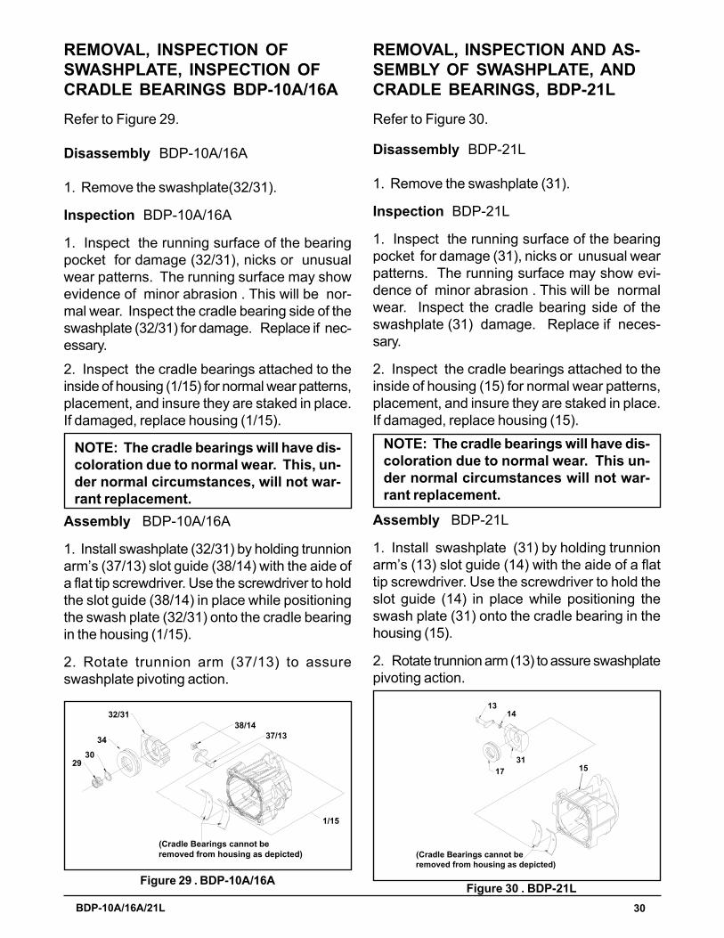
REMOVAL, INSPECTION OFSWASHPLATE, INSPECTION OFCRADLE BEARINGS BDP-10A/16ARefer to Figure 29.
Disassembly BDP-10A/16A
1. Remove the swashplate(32/31).
Inspection BDP-10A/16A
1. Inspect the running surface of the bearingpocket for damage (32/31), nicks or unusualwear patterns. The running surface may showevidence of minor abrasion . This will be nor-mal wear. Inspect the cradle bearing side of theswashplate (32/31) for damage. Replace if nec-essary.
NOTE: The cradle bearings will have dis-coloration due to normal wear. This, un-der normal circumstances, will not war-rant replacement.
REMOVAL, INSPECTION AND AS-SEMBLY OF SWASHPLATE, ANDCRADLE BEARINGS, BDP-21LRefer to Figure 30.
Figure 30 . BDP-21L
2. Inspect the cradle bearings attached to theinside of housing (1/15) for normal wear patterns,placement, and insure they are staked in place.If damaged, replace housing (1/15).
Assembly BDP-10A/16A
1. Install swashplate (32/31) by holding trunnionarm�s (37/13) slot guide (38/14) with the aide ofa flat tip screwdriver. Use the screwdriver to holdthe slot guide (38/14) in place while positioningthe swash plate (32/31) onto the cradle bearingin the housing (1/15).
2. Rotate trunnion arm (37/13) to assureswashplate pivoting action.

31 BDP-10A/16A/21L
REMOVAL, INSPECTION AND AS-SEMBLY OF INPUT SHAFT BDP-10ARefer to Figure 31.
Disassembly BDP-10A
1. Remove the retaining ring (22).
2. Remove the lip seal (20).
3. Remove the spacer (21).
4. Remove the shaft assembly (18) from the BDP.
Inspection BDP-10A
1. Inspect the input shaft (18) for worn splines,surface damage, or keyway damage. Replaceshaft assembly if necessary.
2. Inspect the bearing (19) for evidence of scor-ing, corrosion, or damage. Replace shaft as-sembly if necessary.
3. Inspect and replace the spacer (21) if it isbent or broken.
4. Inspect and replace the retaining ring (22) ifit is bent or broken.
Note: Replace the input shaft seal (20)after removal.
Note: If trunnion arm is to be removed,delay reassembly of input shaft assem-bly.
Assembly BDP-10A
Note: Upon removal, it is recommendedthat all seals, O-rings and gaskets be re-placed. During installation, lightly lubri-cate all seals, O-rings and gaskets withclean petroleum jelly prior to assembly.Also, protect the inner diameter of sealsby covering the shaft with plastic wrap.
1. Install input shaft assembly (18) into the hous-ing (1) bore. Light tapping with a rubber malletmay be necessary on the input shaft (18) oncethe bearing is aligned with the housing (1) bore.Rotate the input shaft (18) to insure free move-ment.
2. Install spacer (21).
3. Install new lip seal (20).
4. Install retaining ring (22).
18
1923
21
20
22
1
Figure 31. BDP-10A
32 BDP-10A/16A/21L
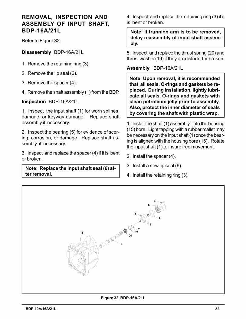
REMOVAL, INSPECTION ANDASSEMBLY OF INPUT SHAFT,BDP-16A/21LRefer to Figure 32.
Disassembly BDP-16A/21L
1. Remove the retaining ring (3).
2. Remove the lip seal (6).
3. Remove the spacer (4).
4. Remove the shaft assembly (1) from the BDP.
Inspection BDP-16A/21L
1. Inspect the input shaft (1) for worn splines,damage, or keyway damage. Replace shaftassembly if necessary.
2. Inspect the bearing (5) for evidence of scor-ing, corrosion, or damage. Replace shaft as-sembly if necessary.
3. Inspect and replace the spacer (4) if it is bentor broken.
Note: Replace the input shaft seal (6) af-ter removal.
Figure 32. BDP-16A/21L
15
1
2019
22
4
36
5
4. Inspect and replace the retaining ring (3) if itis bent or broken.
Note: If trunnion arm is to be removed,delay reassembly of input shaft assem-bly.
5. Inspect and replace the thrust spring (20) andthrust washer (19) if they are distorted or broken.
Assembly BDP-16A/21L
Note: Upon removal, it is recommendedthat all seals, O-rings and gaskets be re-placed. During installation, lightly lubri-cate all seals, O-rings and gaskets withclean petroleum jelly prior to assembly.Also, protect the inner diameter of sealsby covering the shaft with plastic wrap.
1. Install the shaft (1) assembly, into the housing(15) bore. Light tapping with a rubber mallet maybe necessary on the input shaft (1) once the bear-ing is aligned with the housing bore (15). Rotatethe input shaft (1) to insure free movement.
2. Install the spacer (4).
3. Install a new lip seal (6).
4. Install the retaining ring (3).

33 BDP-10A/16A/21L
REMOVAL, INSPECTION TRUNNIONARM BDP-10A/16ARefer to Figure 33.
Disassembly BDP-10A/16A
1. Remove and discard the trunnion seal retainerand seal (49/12).
2. Remove the slot guide (38/14).
3. Remove the trunnion arm (37/13).
Inspection BDP-10A/16A
1. Inspect the trunnion arm (37/13) for wear ordamage. Replace the trunnion arm if necessary.
Assembly BDP-10A/16A
1. Install the trunnion arm (37/13) into the hous-ing (1/15) bore. Rotate the trunnion arm to in-sure free movement.
2. Install a new seal and seal retainer.
3. To completely reassemble the pump, refer tothe assembly steps on pages 19-33. Begin withthe trunnion arm assembly steps listed on page33 and complete the assembly steps in reverseorder working towards the front of the manual.
Note: Upon removal, it is recommendedthat all seals, O-rings, and gaskets be re-placed. During installation, lightly lubri-cate all seals, O-rings and gaskets withclean petroleum jelly prior to assembly.Also protect the inner diameter of sealsby covering the shaft with plastic wrap.Remove the plastic wrap after the seal isinstalled.
Figure 33. BDP-10A/16A
REMOVAL, INSPECTION TRUNNIONARM BDP-21LRefer to Figure 34.
Disassembly BDP-21L
1. Remove trunnion seal retainer (10) and seal(12).
2. Remove slot guide (14).
3. Remove trunnion arm (13).
Inspection BDP-21L
1. Inspect the trunnion arm (13) for wear or dam-age. Replace trunnion if necessary.
Assembly BDP-21L
1. Install the trunnion arm (13) into the housing(15) bore. Rotate the trunnion arm to insure freemovement.
2. Install a new seal and seal retainer.
3. To completely reassemble the pump, refer tothe assembly steps on pages 19-33. Begin withthe trunnion arm assembly steps listed on page33 and complete the assembly steps in reverseorder working towards the front of the manual.
14 1012
16
13
Figure 34. BDP-21L
Note: Upon removal, it is recommendedthat all seals, O-rings, and gaskets be re-placed. During installation, lightly lubri-cate all seals, O-rings and gaskets withclean petroleum jelly prior to assembly.Also protect the inner diameter of sealsby covering the shaft with plastic wrap.Remove the plastic wrap after the seal isinstalled.
1/15
38/14
37/13
49/12

34 BDP-10A/16A/21L
NOTES
35 BDP-10A/16A/21L
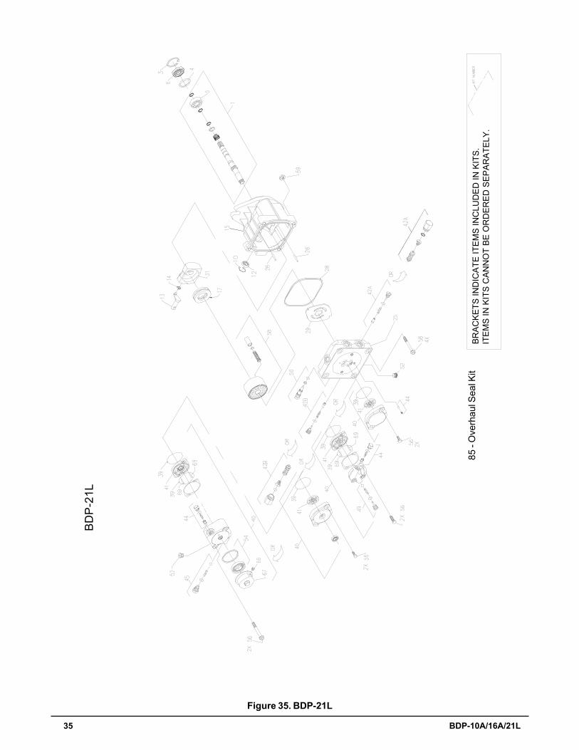
Figure 35. BDP-21L
B RAC
KE T
S IN
DIC
ATE
ITE
MS
INC
LUD
ED
IN K
ITS.
ITE
MS
IN K
ITS
CAN
NO
T BE
OR
DER
ED S
EPA
RA
TELY
.85
- O
verh
aul S
eal K
it
BD
P-2
1L

36 BDP-10A/16A/21L
ITEMS LIST BDP-21LPart numbers are not provided in this manual. See microfiche or CD for part numbers.
Table 7. BDP-21L
No. Description1 Kit Pump Shaft (19T spline)
Kit Pump Shaft (closed key)Kit Pump Shaft (thru shaft spline)Kit Pump Shaft (tapered thru shaft)Kit Pump Shaft (shaft - thru pump)Retaining Ring
4 Spacer5 Shaft Ball Bearing6 Lip Seal 17 x 47 x 8 PTCN110 Trunion Seal Retaining Ring12 Lip Seal 15 x 27 x 713 Trunnion Arm14 Slot Guide15 Housing Kit17 Thrust Ball Bearing Assembly19 Block Thrust Washer20 Block Spring25 Endcap Kit (w/poppets)
End Cap Kit (w/ poppets, .078� cooling orifice)End Cap Kit (w/SCR'S)End Cap Kit (Aux w/ poppets)End Cap Kit (Aux w/ SCR's)End Cap Kit (Aux w/LH:SCR and RH:poppet)End Cap Kit (w/LH: poppet and RH:SCR)
26 Pin28 O-Ring29 Valve Plate31 Variable Swashplate38 Cylinder Block Kit39 O-Ring
R-Ring (-144)40 Charge Pump Kit (0.19 std splined)
Charge Pump Kit (0.13 std splined)Charge Pump Kit (0.13 std thru shaft)Charge Pump Kit (0.13 std spline,clear zinc cover)Charge Pump Kit (CW - splined Aux, 40-70 psi)Charge Pump Kit (CW - splined Aux,135-165 psi)Charge Pump Kit (CCW - splined Aux, 40-70 psi)
No. Description41 Gerotor Assembly (0.19 in3/rev)
Aux Gerotor & HSG Assembly (0.19 in3/rev)Gerotor Assembly (0.13 in3/rev)
42 Check Valve Kit (0.031")Check Valve Kit (0.044")Check Valve Kit (blank)System Check/Relief Kit
44 Charge Relief Kit (w/ 1/2� SAE valve plug, 40-70 psi)Charge Relief Kit (w/ 1/2� SAE valve plug,135-165 psi)Charge Relief Kit (w/ 9/16� SAE valve plug)Charge Relief Kit (w/ 9/16� SAE valve plug, 75-105 psi)Charge Relief Kit (7/32" plastic ball & spring)Charge Relief Kit (1/4� plastic ball & spring)
45 Aux Relief Valve Kit49 Aux Bypass/Check Kit50 Bypass Valve Kit (blank)
Bypass Valve Kit (0.031")54 Auxiliary Filter Kit56 Hex Screw, 5/16-18 x 1.0
Hex Hd Cap Screw, 5/16-18 x 1.38Flange Hd Screw, 5/16-18 x 2.5
58 Hex Screw, Flanged Head59 Hex Flange Nut69 Pin85 Overhaul Seal Kit
Charge Pump Kit (AL Aux, 7/16 SAE port, 40-70 psi)Charge Pump Kit (AL Aux, 7/16 SAE port, 75-105 psi)

37 BDP-10A/16A/21L
Figure 36. BDP-16A
BD
P-1
6A
99 -
OVE
RH
AU
L SE
AL K
IT

38 BDP-10A/16A/21L
ITEMS LIST BDP-16APart numbers are not provided in this manual. See microfiche or CD for part numbers.
Table 8. BDP-16A
No. Description1 Pump Shaft Kit (19T spline)
Pump Shaft Kit (17mm keyed)Pump Shaft Kit (17mm keyed thru taper)Pump Shaft Kit ( double tapered thru shaft)
3 Retaining Ring4 Spacer5 Shaft Ball Bearing6 Lip Seal 17 x 47 x 8 PTCN112 Trunnion Seal Kit13 Trunnion Arm14 Slot Guide15 Housing Kit17 Thrust Ball Bearing Assembly19 Block Thrust Washer20 Block Spring25 End Cap Kit (w/poppets & std chg)
End Cap Kit (w/poppets & aux chg)26 Pin28 O-Ring29 Valve Plate31 Variable Swashplate38 Cylinder Block Kit (16cc)39 O-Ring
R-Ring (-144)40 Charge Pump Kit (.19 std splined)
Charge Pump Kit (.13 std thru shaft)Charge Pump Kit (CW-Iron Aux, 40-70 psi, .001� shim)Charge Pump Kit (CW-Iron Aux, 135-165 psi, .001� shim)Charge Pump Kit (CCW-Iron Aux, 40-70 psi, .001� shim)Charge Pump Kit (Al Aux, 7/16 SAE port, 40-70 psi, .001� shim)Charge Pump Kit (Al Aux 7/16 SAE port, 75-105 psi,.001� shim)
No. Description41 Gerotor Assembly (.13 cu. in./rev)
Gerotor Assembly (.19 cu. in./rev.)Aux Gerotor & Hsg Assembly (0.19 cu.in./rev.)
42 Check Valve Kit (blank orifice)Check Valve Kit (.024� orifice)Check Valve Kit (.031� orifice)Check Valve Kit (.044� orifice)Shock Valve Kit (blank orifice)Shock Valve Kit (.024� orifice)Shock Valve Kit (.031� orifice)Shock Valve Kit (.044� orifice)
44 Charge Relief Kit (1/4� plastic ball & spring)Charge Relief Kit (1/4� plastic ball & spring)Charge Relief Kit ( w/ 9/16� SAE valve plug,
40-70 psi)Charge Relief Kit (w/ 9/16� SAE valve plug,
75-105 psi)Charge Relief Kit (w/ 1/2� SAE valve plug,
40-70 psi)Charge Relief Kit (w/ 1/2� SAE valve plug,
135-165 psi)45 Aux Relief Valve Kit49 Aux Bypass/Check Kit50 Bypass Valve Kit (blank orifice)
Bypass Valve Kit (.031� orifice)Bypass Valve Kit (.043� orifice)
54 Auxiliary Filter Kit56 Socket Hd Cap Screw (M8 x 1.25-25mm)
Flange Hd Screw (5/16-18 x 2.5)58 Hex Screw, Flanged Hd (M10 x1.50-65mm)69 Dowel Pin99 Overhaul Seal Kit

39 BDP-10A/16A/21L
Figure 37. BDP-10A
100
- O
verh
aul S
eal K
it
BO
XE
S IN
DIC
ATE
ITE
MS
INC
L UD
ED IN
KIT
S.
ITE
MS
IN K
ITS
CA
NN
OT
BE
OR
DE R
ED
SE
P AR
ATE
L Y.
BD
P-1
0A
35
90
6
18
2542
A
OB
SO
LETE
44
42A
6
54
456
242
B
49
1
110
42B
OB
SO
LETE
15
44
1032
3430
2938
3721
3169
7
6656
7
4X 4
66
3
5610
798
94
104
103
105
101
100 10
4 106
102
1010
OR
OR
OR
OR
(PO
RT
"A"
SID
E)
(PO
RT
"A"
SID
E)
85
22
20
19
59
59
75
8
5

40 BDP-10A/16A/21L
ITEMS LIST BDP-10APart numbers are not provided in this manual. See microfiche or parts manual for part numbers.
Table 9. BDP-10A
No. Description1 Housing Kit2 End Cap Kit (W/ Poppets, Standard Charge)
End Cap Kit (W/ SCR'S, Standard Charge)End Cap Kit (W/ Poppets, Auxiliary Charge)End Cap Kit (W/ SCR'S & Auxiliary Charge)End Cap Kit (STD CHG) LH:SCR / RH:PoppetEnd Cap Kit (STD CHG) LH:Poppet / RH:SCREnd Cap Kit (AUX CHG) LH:SCR / RH:PoppetEnd Cap Kit (AUX CHG) LH:Poppet / RH:SCREnd Cap Kit (STD CHG) LH:SCR / RH:Poppet,ThruEnd Cap Kit (STD CHG) W/Poppets, ThruEnd Cap Kit (STD CHG) W/SCR�s, ThruEnd Cap Kit (STD CHG) LH:Poppet/ RH:SCR,Thru
3 Straight Headless Pin4 Hex Flange Bolt M8-1.25 X 60mm LG5 Housing O-Ring6 Charge Pump Kit (STD)
Charge Pump Kit (STD CHG), ThruAux Pump Kit (AL., 15T Splined, 2-7/16 SAE Ports)Aux Pump kit (AL., 15T Splined, 3-7/16 SAE Ports)
7 STD Gerotor Assy (.11 cu. In/rev D-Drive)Auxiliary Gerotor & Housing Assembly
8 O-Ring10 Socket Head Screw M6 x 1.0-20mm Lg (STD Chg)
Hex Flange Bolt 8M-1.25 x 60mm (Aux Chg)Cap Screw, Hex 5/16-18 x 1.00 (Thru Chg) Suppliedwith item #2 only
15 Bypass Valve Kit (Blank)Bypass Valve Kit (0.031")Bypass Valve Kit (0.043")
18 Pump Shaft Kit (Blind 15mm Keyway W/ Std Chg)Pump Shaft Kit (Blind 15mm Keyway W/Aux Chg)Pump Shaft Kit (9 Tooth W/Std Chg)Pump Shaft Kit (9 Tooth W/Aux Chg)Pump Shaft Kit (15mm Keyed, Std Chg, Thru)Pump Shaft Kit (9 tooth Thru Chg)Pump Shaft Kit (Tapered)
19 Ball Bearing 17 x 40 x 1220 Lip Seal 17 x 40 x 7 PTC21 Spacer22 Retaining Ring25 Cylinder Block Kit29 Block Spring30 Block Thrust Washer31 Valve Plate (Steel N-Tec:Black)32 Swashplate
No. Description34 Ball Thrust Bearing35 Stud, Torque37 Trunnion Arm
Trunnion, RTN38 Slot Guide42 Check Valve Kit (Blank Orifice)
Check Valve Kit (0.024"Orifice)Check Valve Kit (0.031"Orifice)Check Valve Kit (0.044"Orifice)System Check / Relief KitSystem Check Relief Kit(.031� Orifice)Shock Valve Kit
44 Charge Relief Valve Kit (1/4"Plastic Ball & 50654 Spring)Charge Relief Valve Kit (9/16�SAE Plug & 3101536 Spring)
45 Aux Relief Valve Kit (1/4" SteelBall)Aux Relief Valve Kit (AuxPoppet)
49 Trunnion Seal/ Retainer Kit54 Auxiliary Filter Kit56 Straight Thread Plug59 O-Ring66 5/16" SAE Plug67 Filter Cover69 Straight Headless Pin75 Shim - Charge Pump (.002-
Red)85 R-Ring -14490 Hub / 6� Fan Kit
Hub / 7� CCW Fan KitHub / 7� CW Fan KitHub / 7� Fan Kit
100 Overhaul Seal Kit101 Spacer RTN102 Spring, Extension103 Screw, 5/16 x .875 (patch)104 Washer .34 x .88 x .06105 Washer, Nylon106 Nut, Hex Lock 5/16-24 UNF107 Spacer110 Kit, RTN, STD
Kit, RTN, CWKit, RTN, CCW

41 BDP-10A/16A/21L
Axial Piston: Type of design for hydraulic motors and pumps in which the pistons are arrangedparallel with the spindle (input or output shaft).
Bantam Duty: A descriptive term relating to the product capacity (meaning: light duty).
Bypass Valve: A valve whose primary function is to open a path for the fluid to bypass the motor orpump. Also referred to occasionally as the freewheel valve or dump valve.
Case Drain Line (Return Line): A line returning fluid from the component housing to the reservoir.
Cavitation: A phenomenon of boiling in a flowing liquid at normal temperatures, as a result of lowpressure condition. The gas liberated from the fluid implodes rapidly and damages pump compo-nents.Center Section: A device which acts as the valve body and manifold of the transmission.
Charge Pump: A device which supplies replenishing fluid to the fluid power system (closed loop).
Charge Pressure: The pressure at which replenishing fluid is forced into a fluid power system.
Charge Relief Valve: A pressure control valve whose primary function is to limit pressure in thecharge circuit.
Check Valve: A valve whose primary function is to restrict flow in one direction.
Closed Loop: A sealed and uninterrupted circulating path for fluid flow from the pump to the motorand back.
Decay Rate: The ratio of pressure decay over time.
End Cap: See �Center Section�
Entrained Air: A mechanically generated mixture of air bubbles having a tendency to separate fromthe liquid phase.
Gerotor: A fixed displacement pump frequently used as a charge pump.
Hydraulic Motor: A device which converts hydraulic fluid pressure and flow into mechanical forceand motion.
Hydraulic Pump: A device which converts mechanical force and motion into hydraulic fluid pres-sure and flow.
Hydrostatic Motor: See �Hydraulic Motor�
Hydrostatic Pump: See �Hydraulic Pump�
GLOSSARY OF TERMS

42 BDP-10A/16A/21L
Hydrostatic Transaxle: A multicomponent assembly including a gear case and a hydrostatic trans-mission.
Hydrostatic Transmission: The combination of a hydraulic pump and motor in one housing to forma device for the control and transfer of power.
Inlet Line: A supply line to the pump.
Integrated Hydrostatic Transaxle (IHT): The combination of a hydrostatic transmission and gearcase in one housing to form a complete transaxle.
Manifold: A conductor which provides multiple connection ports.
Neutral: Typically described as a condition in which fluid flow and system pressure is below thatwhich is required to turn the output shaft of the motor.
Pressure Decay: A falling pressure.
Priming: The filling of the charge circuit and closed loop of the fluid power system during start up,frequently achieved by pressurizing the fluid in the inlet line.
Purging: The act of replacing air with fluid in a fluid power system.
Rated Flow: The maximum flow that the power supply system.
Scoring: Scratches in the direction of motion of mechanical parts caused by abrasive contami-nants.
Swash Plate: A mechanical device used to control the displacement of the pump pistons in a fluidpower system.
System Charge Check Valve: A valve controlling the replenishing flow of fluid from a charge circuitto the closed loop in a fluid power system.
System Pressure: The pressure which overcomes the total resistance in a system, including allefficiency losses.
Valve: A device which controls fluid flow direction, pressure, or flow rate.
Variable Displacement Pump: A pump in which the displacement per revolution can be varied.
Volumetric Displacement: The fluid volume for one revolution.

43 BDP-10A/16A/21L
NOTES

44 BDP-10A/16A/21L
NOTES

45 BDP-10A/16A/21L
© 2003 HYDRO-GEARPrinted in U.S.A.