b.e: electrical and electronics engineering · digital logic gate, and amplifier, -current biasing,...
TRANSCRIPT
B.E: Electrical and Electronics Engineering
(2018-2019)
Curriculum Structure
&
Syllabus
(3rd & 4th semesters)
Department of Electrical and Electronics Engineering
The National Institute of Engineering
Mysuru-570 008
Department of Electrical and Electronics Engineering

Department Vision
The department will be an internationally recognized centre of excellence imparting quality education in electrical engineering for the benefit of academia, industry and society at large.
Department Mission
M1: Impart quality education in electrical and electronics engineering through theory and its applications by dedicated and competent faculty.
M2: Nurture creative thinking and competence leading to innovation and technological growth in the overall
ambit of electrical engineering M3: Strengthen industry-institute interaction to inculcate best engineering practices for sustainable
development of the society
Program Educational Objectives
PEO1: Graduates will be competitive and excel in electrical industry and other organizations
PEO2:Graduates will pursue higher education and will be competent in their chosen domain
PEO3:Graduates willdemonstrate leadership qualities with professional standards for sustainable
development of society
PROGRAM OUTCOMES
Engineering Graduates will be able to:
1. Engineering knowledge: Apply the knowledge of mathematics, science, engineering fundamentals and an engineering specialization to the solution of complex engineering problems.
2. Problem analysis: Identify, formulate, review research literature, and analyze complex engineering
problems reaching substantiated conclusions using first principles of mathematics, natural sciences and engineering sciences.
3. Design/development of solutions: Design solutions for complex engineering problems and design
system components or processes that meet the specified needs with appropriate consideration for the public health and safety and the cultural, societal and environmental considerations.
4. Conduct investigations of complex problems: Use research-based knowledge and research methods
including design of experiments, analysis and interpretation of data and synthesis of the information to provide valid conclusions.
5. Modern tool usage: Create, select and apply appropriate techniques, resources and modern
engineering and IT tools including prediction and modeling to complex engineering activities with an understanding of the limitations.
6. The engineer and society: Apply reasoning informed by the contextual knowledge to assess societal,
health, safety, legal and cultural issues and the consequent responsibilities relevant to the professional engineering practice.
7. Environment and sustainability: Understand the impact of the professional engineering solutions in
societal and environmental contexts and demonstrate the knowledge of and need for sustainable development.
8. Ethics: Apply ethical principles and commit to professional ethics and responsibilities and norms of
the engineering practice.
9. Individual and team work: Function effectively as an individual and as a member or leader in diverse teams and in multidisciplinary settings.
10. Communication: Communicate effectively on complex engineering activities with the engineering
community and with society at large, such as, being able to comprehend and write effective reports and design documentation, make effective presentations and give and receive clear instructions.
11. Project management and finance: Demonstrate knowledge and understanding of the
engineering and management principles and apply these to one’s own work, as a member and leader in a team, to manage projects and in multidisciplinary environments.
12. Life-long learning: Recognize the need for and have the preparation and ability to engage in
independent and life-long learning in the broadest context of technological change.
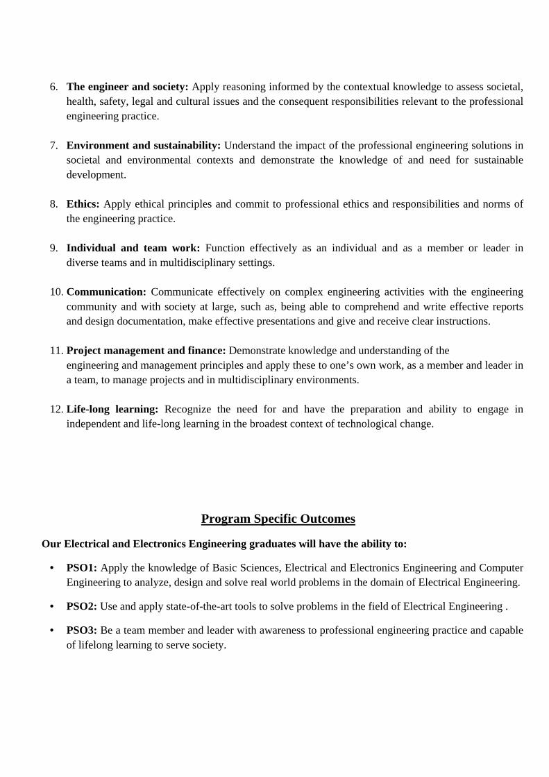
Program Specific Outcomes
Our Electrical and Electronics Engineering graduates will have the ability to:
• PSO1: Apply the knowledge of Basic Sciences, Electrical and Electronics Engineering and Computer Engineering to analyze, design and solve real world problems in the domain of Electrical Engineering.
• PSO2: Use and apply state-of-the-art tools to solve problems in the field of Electrical Engineering .
• PSO3: Be a team member and leader with awareness to professional engineering practice and capable of lifelong learning to serve society.
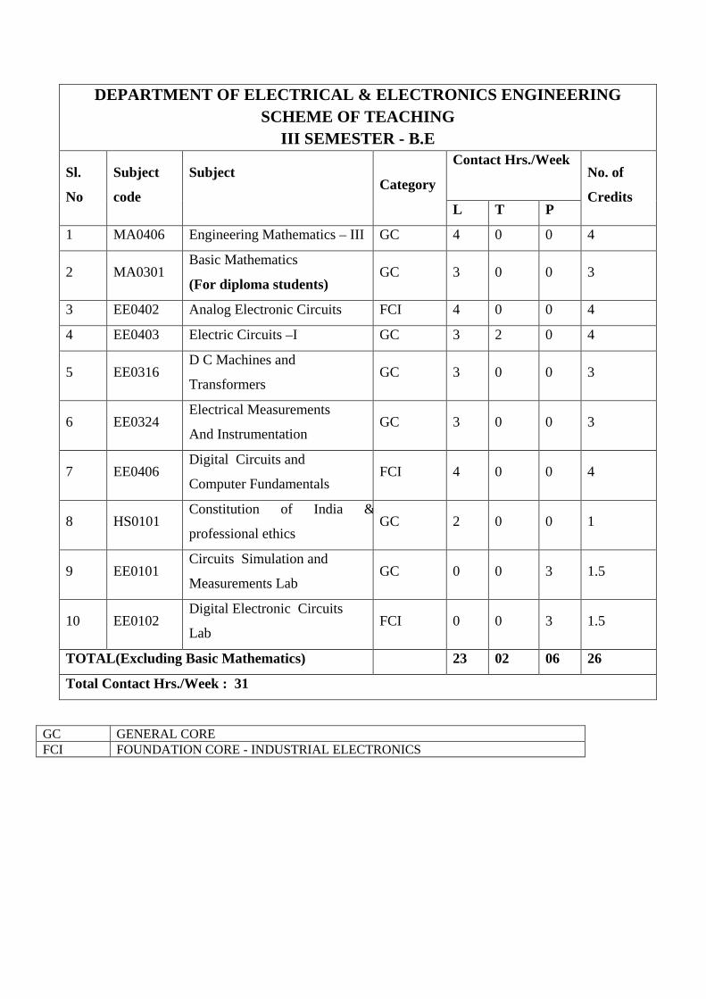
DEPARTMENT OF ELECTRICAL & ELECTRONICS ENGINEERING SCHEME OF TEACHING
III SEMESTER - B.E
Sl.
No
Subject
code
Subject
Category
Contact Hrs./Week
No. of
Credits L T P
1 MA0406 Engineering Mathematics – III GC 4 0 0 4
2 MA0301 Basic Mathematics
(For diploma students) GC 3 0 0 3
3 EE0402 Analog Electronic Circuits FCI 4 0 0 4
4 EE0403 Electric Circuits –I GC 3 2 0 4
5 EE0316 D C Machines and
Transformers GC 3 0 0 3
6 EE0324 Electrical Measurements
And Instrumentation GC 3 0 0 3
7 EE0406 Digital Circuits and
Computer Fundamentals FCI 4 0 0 4
8 HS0101 Constitution of India &
professional ethics GC 2 0 0 1
9 EE0101 Circuits Simulation and
Measurements Lab GC 0 0 3 1.5
10 EE0102 Digital Electronic Circuits
Lab FCI 0 0 3 1.5
TOTAL(Excluding Basic Mathematics) 23 02 06 26
Total Contact Hrs./Week : 31
GC GENERAL CORE FCI FOUNDATION CORE - INDUSTRIAL ELECTRONICS
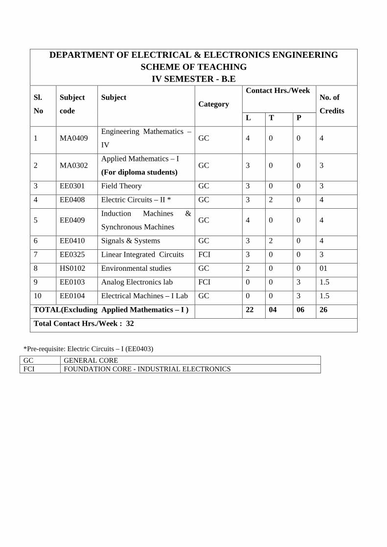
*Pre-requisite: Electric Circuits – I (EE0403)
DEPARTMENT OF ELECTRICAL & ELECTRONICS ENGINEERING SCHEME OF TEACHING
IV SEMESTER - B.E
Sl.
No
Subject
code
Subject
Category
Contact Hrs./Week
No. of
Credits L T P
1 MA0409 Engineering Mathematics –
IV GC 4 0 0 4
2 MA0302 Applied Mathematics – I
(For diploma students) GC 3 0 0 3
3 EE0301 Field Theory GC 3 0 0 3
4 EE0408 Electric Circuits – II * GC 3 2 0 4
5 EE0409 Induction Machines &
Synchronous Machines GC 4 0 0 4
6 EE0410 Signals & Systems GC 3 2 0 4
7 EE0325 Linear Integrated Circuits FCI 3 0 0 3
8 HS0102 Environmental studies GC 2 0 0 01
9 EE0103 Analog Electronics lab FCI 0 0 3 1.5
10 EE0104 Electrical Machines – I Lab GC 0 0 3 1.5
TOTAL(Excluding Applied Mathematics – I ) 22 04 06 26
Total Contact Hrs./Week : 32
GC GENERAL CORE FCI FOUNDATION CORE - INDUSTRIAL ELECTRONICS
BASIC MATHEMATICS (3:0:0)
(FOR DIPLOMA STUDENTS OF III SEMESTER)
Sub Code : MA0301 CIE : 50% Marks Hrs/Week : 03 SEE : 50% Marks SEE Hrs : 03 Total: 39 hrs Max. : 100 Marks Course Outcomes: On successful completion of the course the students will be able to:
1. Identify some standard curves. Translate any differentiable function into power series & compute partial derivatives.
2. Compute measures of central tendency and dispersion for a given statistical data. 3. Compute integrals using appropriate methods and Beta - Gamma functions. Evaluate multiple integrals. 4. Define a Fourier series and translate the periodic function of period 2l in terms of Fourier series, half range series. 5. Solve first order differential equations using appropriate methods and also solve linear second and higher order differential equations with constant coefficients
Module - I
Differential Calculus Introduction to some standard curves. Basic concepts of differentiation. Expansion of functions – Taylor’s and Maclaurin’s expansion of a function of one variable. Partial differentiation, Total derivative and Chain rule – simple problems (SLE: Jacobians). 8 hrs
Module - II Statistics Measures of central tendency- mean, median for grouped and ungrouped data, Measures of dispersion- Quartile deviation, Mean deviation and Standard deviation. Simple application problems (SLE: Mode). 8 hrs
Module - III Integral Calculus Evaluation of definite integrals by the method of substitution, integration by parts, Bernoulli’s rule of integration. Evaluation of double and triple integrals. Beta and Gamma functions – Definition, Properties, problems on relation between beta and gamma function ((SLE: Evaluation of double integrals by converting into polar form, derivation of alternate formulae of Beta and Gamma functions). 8 hrs
Module - IV Fourier Series Periodic functions, Fourier series, Dirichlet’s conditions for a Fourier series, Euler’s Fourier coefficients. Fourier series of period 2l – continuous and discontinuous functions, even and odd functions, Half range series, Practical harmonic analysis (SLE: Fourier series with period 2𝜋𝜋).
8 hrs
Module - V
Differential Equations Solution of first order and first degree differential equations – separation of variables, linear, exact. Solution of higher order non-homogeneous differential equations - P.I for: eax, sin(ax)/cos(ax), xn (SLE: Bernoulli’s differential equation). 7 hrs Text Books:
1. Higher Engineering Mathematics by Dr. B. S. Grewal, 42nd edition, Khanna publications. 2. Higher Engineering Mathematics by H.K.Dass , (2008 edition), Chand Publications.
Reference Books: 1. Advanced Engineering Mathematics – Erwin Kreyszig, vol I & II, wiley publications,
10th edition. 2. N. P. Bali and Manish Goyal : Engineering Mathematyics, Laxmi publishers, 7th Ed. 2007.
Analog Electronic Circuits (4-0-0)
Sub Code : EE0402 CIE: 50% Mark Hrs/Week : 4+0+0 SEE: 50% Marks SEE Hrs : 3 Max. Marks: 100 Course Outcomes On successful completion of the course, the students will be able to:
1. Analyse diode clipping and clamping circuits for wave shaping.
2. Analyse biasing circuits, transistor equivalent circuits and frequency response characteristics.
3. Explain the working principle of oscillator and amplifier circuits.
4. Discuss the applications of transistor and MOSFET circuits.
UNIT 1: Basic Bipolar Junction Transistor, DC analysis of transistor circuits, basic transistor applications,
bipolar transistor biasing and design. Diode clipping and clamping circuits.
10 Hours
SLE: Diode thermometer with a bipolar transistor
UNIT 2: BJT Amplifiers,BJT transistor modeling ,The re Transistor Model, Hybrid equivalent model,
General frequency consideration, Low frequency response of BJT amplifier, Miller Effect capacitance, high
Frequency response of BJT amplifier.
9 Hours
SLE: Multistage amplifier and frequency response.
UNIT 3: Oscillator operation, RC Phase shift oscillator, Weinbridge Oscillator, Tuned Oscillator circuits.
Introduction to Power amplifiers, series fed class A amplifier, Transformer coupled Class A amplifier, Class
B amplifier operations, Class B amplifier circuits, Class C and Class D Amplifiers.
9 Hours
SLE: Crystal oscillator.
UNIT 4: MOS Field-Effect Transistor, MOSFET DC Circuit Analysis, Basic MOSFET Applications: Switch
Digital Logic Gate, and Amplifier, Constant-Current Biasing, Multistage MOSFET Circuits, Junction Field-
Effect Transistor.
8 Hours
SLE: Diode Thermometer with MOSFET.
UNIT 5: MOSFET Amplifier, Basic Transistor Amplifier Configurations, Common-Source Amplifier,
Common-Drain (Source-Follower) Amplifier. 8 Hours
SLE: Common-Gate Configuration.
UNIT 6: Single-Stage Integrated Circuit MOSFET Amplifiers, Multistage Amplifiers, Basic JFET Amplifiers
8 Hours
SLE: Two-Stage MOSFET amplifier
Text Books:
1. Donald A. Neamen,“Microelectronics: Circuit Analysis and Design”,4thedition,McGraw-Hill, 2010.
2. RobertL. Boylestad and Louis Nashelsky,“Electronic Devices and Circuit Theory”,9th edition,
PHI/Pearson Education, 2006.
3. J. Millman, Taub, "Pulse Digital and Switching Waveforms",Tata-McGraw Hill,1991.
4. Adel S. Sedra and Kenneth C. Smith, “Microelectronic Circuits”, 5th edition, Newyork Oxford,
OXFORD UNIVERSITY PRESS 2004.
Reference Books: 1. Jacob Millman and Christos C. Halkias “Integrated Electronics”, 2nd edition, Tata-McGraw
Hill,2010.
2. David A. Bell,“Electronic Devices and Circuits”, 4th edition, PHI, 2004.
Open Courseware:
1. nptel.ac.in/courses/122106025/

Electric Circuits-I (3-2-0)
Sub code : EE0403 CIE : 50% Marks Hrs/Week : 3+2+0 SEE : 50% Marks SEE Hrs : 3 Max. Marks: 100 Course Outcomes On successful completion of the course, the students will be able to:
1. Solve electrical networks by applying Kirchhoff’s laws and network theorems. 2. Analyze the frequency response of resonant circuits. 3. Analyze poly-phase systems for different configurations.
UNIT 1 :Analysis of DC Networks: Sources, Source Conversions, Sources in Parallel, Sources in Series,
Branch Current Analysis, Mesh Current Analysis (General and Formal Approaches), Nodal analysis (General
and Formal Approaches), Y-Δ and Δ_Y Conversions.
8 Hours
SLE: Bridge Networks
UNIT 2: Application of Theorems to DC Networks: Superposition Theorem, Thevenin’s Theorem,
Norton’s Theorem, Maximum Power Transfer Theorem, Millman’s Theorem, Reciprocity Theorem.
9 Hours
SLE: Substitution Theorem
UNIT 3: Analysis of AC Networks: Independent Versus Dependent (controlled) Sources,Source
Conversions,Mesh Analysis, Nodal analysis,Bridge Networks. 9 Hours
SLE:Y-Δ and Δ_Y Conversions
UNIT 4: Application of Theorems to AC Networks: Superposition Theorem, Thevenin’s Theorem,
Norton’s Theorem, Maximum Power Transfer Theorem, Millman’s Theorem, Substitution Theorem.
8 Hours
SLE: Reciprocity Theorem
UNIT 5 : Resonance and Coupled Circuits:Series Resonant Circuit, Quality Factor,ZT Versus Frequency,
VR, VL and VC, Selectivity, Parallel Resonant Circuit, Selectivity Curve for Parallel Resonant Circuits,
Examples. Mutual Inductance, Iron-Core Transformer, Reflected Impedance and Power, Impedance Matching
and Isolation, Series and parallel connection of mutually coupled circuits, Connection of Mutually Coupled
Circuits, Air-Core Transformer, Networks with Magnetically Coupled Coils.
10 Hours
SLE: Locus diagrams
UNIT 6 : Polyphase Systems: Three-Phase Generator, Y-Connected Generator, Phase Sequence of Y-
Connected Generator, Y-Connected Generator With a Y-Connected Load, Y-Δ System, Δ-Connected
Generator, Phase Sequence of Δ-Connected Generator, Δ-Δ, Δ-Y, Three-Phase Systems, Power, Three-
Wattmeter Method, Two-Wattmeter Method,Unbalanced,Three-Phase,Four-Wire,Y-Connected Load.
8 Hours
SLE: Unbalanced, Three-Phase, Three-Wire, Y-Connected Load
Text Books:
1. Robert L.Boylestad,“Introductory Circuit Analysis”, 12th Edition, Pearson.
Reference Books:
1. W.H.Hayt,J E Kemmerly, S M Durbin, “Engineering Circuit Analysis”,7th edition, Tata McGraw-
Hill Education Private Limited.
2. Joseph Edminster, “Electric Circuits”,Tata McGraw-Hill Publications.
3. T.S.K.V.Iyer, “Theory and Problems in Circuit Analysis”,Tata McGraw-Hill.
4. Parker Smith, “Problems in Electrical Engineering”,CBS Publication.
DC Machines and Transformers (3-0-0)
Sub code : EE0316 CIE : 50% Marks Hrs/Week : 3+0+0 SEE : 50% Marks SEE Hrs : 3 Max. Marks : 100
Course Outcomes
On successful completion of the course, the students will be able to:
1. Understand the concepts DC machine and to evaluate their performance
2. Explain testing of DC machines and principle of operation of special types of DC machines
3. To understand the concepts of transformers and their analysis.
4. Analyze the different types and performance of single phase and three phase transformers.
UNIT 1: Armature reaction in DC Machine and its effects, commutation and use of inter poles, Speed control
by Armature control, Field control and Ward Leonard method of speed control. Dynamic braking and
plugging of DC motor. 7Hours
SLE: Compensating Winding
UNIT 2: Losses in DC Machine, constant and variable losses. Testing of DC Machines Swinburne’s test,
Hopkinson’s test, Retardation test, Fields test on series machine. Basic constructional details and principle of
operation of Permanent magnet DC motor, Brushless DC motor, Servo motor.
7 Hours
SLE: Basic constructional details and principle of operation of Stepper Motor
UNIT 3: Transformer-principle of operation, Construction and types of core, materials used in various parts
of transformer, analysis of single phase transformer-Ideal and practical transformer on NO load with phasor
diagrams, leakage reactance of transformer. Practical transformer on load and its phasor diagram.
Development of equivalent circuit of transformer, Voltage regulation.Numerical Examples
6 Hours
SLE: Simplified equivalent circuit.
UNIT 4: Losses in transformer-Variable loss and constant loss, OC, SC and Sumpner’s test,
Determination of efficiency, Necessity of Parallel operation, conditions for parallel operation – Single phase
and three phase. Load sharing in case of similar and dissimilar transformers, Numerical Examples,Cause and
effects of harmonics, Current inrush in transformers.
7 Hours
SLE: All day efficiency
UNIT 5 :Transformer connection for three phase operation – star/star, delta/delta, star/delta, zigzag/star and
V/V, choice of connection. Phase conversion - Scott connection for three-phase to two-phase conversion.
polarity marking of three-phase transformer, principle of phase shift, three phase phase shifter, phase shift
transformer.
7 Hours
SLE: Open Delta Connection
UNIT 6: Basic aspects of power and distribution transformer, Tertiary winding Transformers, welding,
instrument, constant voltage, constant current, variable frequency, tap changing transformer.Auto transformer,
torroidal current transformer, high impedance transformer and Induction heating transformer.
6 Hours
SLE:High Frequency transformer
Text Books:
1. Dr. P.S.Bhimbra, “Electrical Machines”, 7th edition, Khanna Publishers, 2006.
2. Nagrath and Kothari, “Electrical Machines”, 4th edition, TMH, 2010.
3. Theodre Wildi, “Electrical Machines, Drives and Power Systems”, 6th Edition, Pearson Publications.
4. BHEL Handbook "Transformer" 2ndedition,TataMc-Graw Hill publishing pvt ltd.2003
REFERENCE BOOKS:
1. Ashfaq Hussain, “Electrical Machines”, 2nd edition, DhanpatRai Pub and Co, 2008.
2.E Clayton and Hancock,“Performance and Design of DC Machine”, ELBS Publication.
Open Courseware:
1. nptel.ac.in/courses/108105017
Electrical Measurements and Instrumentation (3-0-0)
Sub code : EE0324 CIE : 50% Marks Hrs/Week : 3+0+0 SEE: 50% Marks SEE Hrs : 3 Max. Marks : 100 Course Outcomes
On successful completion of the course, the students will be able to:
1. Define the functions and characteristics of instruments & measurement systems.
2. Explain the methods of measuring electrical parameters by bridge techniques.
3. Describe the measurement of power & energy in ac & dc circuits.
4. Describe the construction & principle of operation of electromechanical instruments, instrument
transformers and Electronic Instruments.
5. Discuss the functioning and characteristics of transducers.
UNIT 1: Measurements and Measurement Systems: Significance and methods of measurements,
Instruments and Measurements Systems, Mechanical Electrical and Electronics Instruments, Functions and
Characteristics of Instruments and Measurement Systems. Deflection and Null type Instruments, Applications
of Measurement Systems.
4 Hours
SLE: Types of Instrumentation Systems.
UNIT 2: Measurement of Electrical Parameters: Classification of Resistance for Measurements,
Measurement of Low Resistance by Kelvin Double Bridge, Measurement of Medium Resistance by
Wheatstone Bridge, Measurement of High Resistance by Megger, Measurement of Earth Resistance by fall of
Potential Method, Measurement of Inductance by Maxwell’s and Anderson’s Bridge, Measurement of
Capacitance by D’Sauty and Schering Bridge. Illustrative Examples. 8 Hours
SLE: Errors in Bridge Measurements, Shielding of Bridges
UNIT 3: Electro-Mechanical Instruments: Classification of AC and DC Meters, Constructional Details and
Principle of Operation of Electro Dynamometer Type Ammeter and Volt meter. Extension of Instrument
Ranges: Ammeter Shunts, Multi range Ammeter, Voltmeter Multipliers, Multi Range Voltmeters, Illustrative
Examples. Theory, Types, measurement of ratio and phase angle errors of CT and PT, clamp meters.
8 Hours
SLE:DC and AC Potentiometers for calibration
UNIT 4: Measurement of Power and Energy: Power in DC and AC Circuits, Electrodynamometer
Wattmeter, Construction, Working, Theory and Operation of Single Phase Induction type Energy Meter,
Errors, Power factor Meter, Weston Frequency Meter and Phase Sequence Indicator, trivector meter, power
analyser.
Electronic Instruments: True RMS Reading Voltmeter, Electronic Multimeters, Digital Voltmeters:
Integrating and Successive Approximation DVM. 7 Hours
SLE: Digital energy meters
UNIT 5: Oscilloscopes and Signal Generators: Introduction, oscilloscope block diagram, cathode ray tube.
The sine-wave generator and function generator. Sources and detectors.
6 Hours
SLE: Digital Storage Oscilloscopes.
UNIT 6 : Transducers and signal conditioning :Electric transducers, advantages of electric transducers,
primary and secondary transducers, passive and active transducers, analog and digital transducers, transducers
and inverse transducers, characteristics and choice of transducers-input, transfer and output characteristics,
resistive transducers, capacitive transducers, hall effect transducers, Smart grid communications and
Measurement Technology. 7 Hours
SLE: Opto-electronic transducers.
Text Books:
1.A.K.Sawhney, Dhanpat Rai and Sons,“Electrical and Electronic Measurements and Instrumentation”,
4th edition, New Delhi, 1985.
2.Cooper D and A.D. Heifrich, “Modern Electronic Instrumentation and Measuring
Techniques”,Prentice Hall of India, August 2003.
3.James Momoh, “SMART GRID – Fundamentals of Design and Analysis”, IEEE Press, A John Wiley
& Sons, Inc, Publications
Reference Books:
1. David.A.Bell,“Electronic Instrumentation and Measurement”,2nd edition, PHI, 2007.
2. Oliver and Cage, “Electronic Measurements and Instruments”,McGraw-Hill, 1977.
Digital Circuits and Computer Fundamentals (4-0-0)
Sub code : EE0406 CIE : 50% Marks Hrs/Week : 4+0+0 SEE : 50% Marks SEE Hrs : 3 Max. Marks: 100 Course Outcomes
On successful completion of the course, the students will be able to:
1. Simplify Boolean expressions using K-maps.
2. Describe combinational functional blocks, working of flip flops, shift registers and counters.
3. Design combinational and sequential circuits
4. Explain architecture, addressing modes, datapaths, interrupts and I/O transfers of a
computing device.
UNIT 1:Combinational Logic Circuits: Standard Forms, two level circuit optimization, Map Simplification,
Map Manipulation, multiple level circuit optimization, Exclusive OR operator and gates, high impedance
outputs. 7 Hours
SLE: Integrated circuits, technology parameters.
UNIT 2:Combinational Logic Design: Design procedure, hierarchical design, technology mapping,
verification, combinational functional blocks, rudimentary logic functions, decoders, encoders, multiplexers,
iterative combinational circuits, binary adders, binary subtractors, binary adder- subtractors and other
arithmetic functions. 8 Hours
SLE: CMOS circuit technology.
UNIT 3:Sequential Circuits: Definitions, Latches, Flip-flops, Sequential circuit Analysis, Sequential circuits
Design, state machine diagrams and applications. 10 Hours
SLE: State machine design of a sliding door control.
UNIT 4:Registers and register transfers: Registers and load enable, register transfers, register transfer
operations, microoperations, microoperations on a single registers, shift registers, Ripple counter,
synchronous binary counters, other counters, Multiplexer and bus based transfers, serial transfer, serial
addition, control of register transfers. 9 Hours
SLE: Dash watch.
UNIT 5:Instruction set architecture: Computer architecture concepts, operand addressing, addressing
modes, instruction set architectures, floating point computations, program control instructions, program
interrupt. 9Hours
SLE: SRAM cell and DRAM cell.
UNIT 6: Computer design basics: Datapaths, arithmetic logic unit, shifter, datapath representation, control
word, A simple computer architecture, I/O interfacings, serial communication, modes of I/O transfer.
9 Hours
SLE: Direct Memory Access.
Text Book:
1. M Morris Mano and Charles Kime,“Logic and Computer Design Fundamentals”,Fourth Edition,
Pearson Publication, 2014.
Reference Books:
1. John M Yarbrough,“Digital Logic Applications and Design”, Thomson Learning.
2. Donald D Givone, “Digital Principles and Design”,Tata McGraw-Hill edition.
3. Charles H Roth Jr,“Fundamentals of Logic Design”,Thomson Learning.
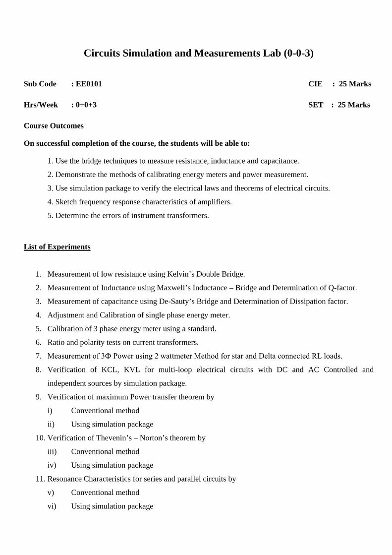
Circuits Simulation and Measurements Lab (0-0-3)
Sub Code : EE0101 CIE : 25 Marks Hrs/Week : 0+0+3 SET : 25 Marks Course Outcomes
On successful completion of the course, the students will be able to:
1. Use the bridge techniques to measure resistance, inductance and capacitance.
2. Demonstrate the methods of calibrating energy meters and power measurement.
3. Use simulation package to verify the electrical laws and theorems of electrical circuits.
4. Sketch frequency response characteristics of amplifiers.
5. Determine the errors of instrument transformers.
List of Experiments
1. Measurement of low resistance using Kelvin’s Double Bridge.
2. Measurement of Inductance using Maxwell’s Inductance – Bridge and Determination of Q-factor.
3. Measurement of capacitance using De-Sauty’s Bridge and Determination of Dissipation factor.
4. Adjustment and Calibration of single phase energy meter.
5. Calibration of 3 phase energy meter using a standard.
6. Ratio and polarity tests on current transformers.
7. Measurement of 3Ф Power using 2 wattmeter Method for star and Delta connected RL loads.
8. Verification of KCL, KVL for multi-loop electrical circuits with DC and AC Controlled and
independent sources by simulation package.
9. Verification of maximum Power transfer theorem by
i) Conventional method
ii) Using simulation package
10. Verification of Thevenin’s – Norton’s theorem by
iii) Conventional method
iv) Using simulation package
11. Resonance Characteristics for series and parallel circuits by
v) Conventional method
vi) Using simulation package
12. Calibration of Ammeter, Voltmeter and Wattmeter using DC potentiometer.
13. Earth resistance testing using meggar.
Reference:
1. “Introduction to Pspice using Or-Cad for Circuits and Electronics”, Rashid, 3rdedition, Pearson
Education Publication.
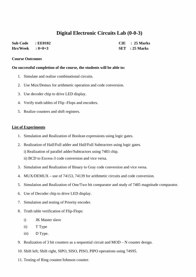
Digital Electronic Circuits Lab (0-0-3)
Sub Code : EE0102 CIE : 25 Marks Hrs/Week : 0+0+3 SET : 25 Marks Course Outcomes
On successful completion of the course, the students will be able to:
1. Simulate and realize combinational circuits.
2. Use Mux/Demux for arithmetic operation and code conversion.
3. Use decoder chip to drive LED display.
4. Verify truth tables of Flip -Flops and encoders.
5. Realize counters and shift registers.
List of Experiments
1. Simulation and Realization of Boolean expressions using logic gates.
2. Realization of Half/Full adder and Half/Full Subtractors using logic gates.
i) Realization of parallel adder/Subtractors using 7483 chip.
ii) BCD to Excess-3 code conversion and vice versa.
3. Simulation and Realization of Binary to Gray code conversion and vice versa.
4. MUX/DEMUX – use of 74153, 74139 for arithmetic circuits and code conversion.
5. Simulation and Realization of One/Two bit comparator and study of 7485 magnitude comparator.
6. Use of Decoder chip to drive LED display.
7. Simulation and testing of Priority encoder.
8. Truth table verification of Flip-Flops:
i) JK Master slave
ii) T Type
iii) D Type.
9. Realization of 3 bit counters as a sequential circuit and MOD – N counter design.
10. Shift left; Shift right, SIPO, SISO, PISO, PIPO operations using 74S95.
11. Testing of Ring counter/Johnson counter.
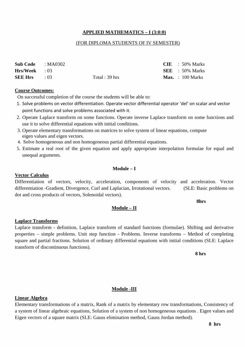
APPLIED MATHEMATICS – I (3:0:0)
(FOR DIPLOMA STUDENTS OF IV SEMESTER)
Sub Code : MA0302 CIE : 50% Marks Hrs/Week : 03 SEE : 50% Marks SEE Hrs : 03 Total : 39 hrs Max. : 100 Marks Course Outcomes: On successful completion of the course the students will be able to: 1. Solve problems on vector differentiation. Operate vector differential operator ‘del’ on scalar and vector
point functions and solve problems associated with it. 2. Operate Laplace transform on some functions. Operate inverse Laplace transform on some functions and
use it to solve differential equations with initial conditions. 3. Operate elementary transformations on matrices to solve system of linear equations, compute eigen values and eigen vectors. 4. Solve homogeneous and non homogeneous partial differential equations. 5. Estimate a real root of the given equation and apply appropriate interpolation formulae for equal and
unequal arguments.
Module – I Vector Calculus Differentiation of vectors, velocity, acceleration, components of velocity and acceleration. Vector differentiation -Gradient, Divergence, Curl and Laplacian, Irrotational vectors. (SLE: Basic problems on dot and cross products of vectors, Solenoidal vectors). 8hrs
Module – II Laplace Transforms Laplace transform - definition, Laplace transform of standard functions (formulae). Shifting and derivative properties – simple problems. Unit step function - Problems. Inverse transforms – Method of completing square and partial fractions. Solution of ordinary differential equations with initial conditions (SLE: Laplace transform of discontinuous functions).
8 hrs
Module -III
Linear Algebra Elementary transformations of a matrix, Rank of a matrix by elementary row transformations, Consistency of a system of linear algebraic equations, Solution of a system of non homogeneous equations . Eigen values and Eigen vectors of a square matrix (SLE: Gauss elimination method, Gauss Jordan method).
8 hrs
Module – IV
Partial Differential Equations Solution of homogeneous and non-homogeneous PDE, Solution of homogeneous PDE by direct integration and method of separation of variables. Various possible solutions of one dimensional wave equation and heat equation (SLE: Solution of homogeneous PDE of one variable).
8 hrs
Module– V Numerical Methods Numerical solution of algebraic and transcendental equations - Newton Raphson method, Finite differences – forward and backward differences, Newton’s forward and backward interpolation formula. Interpolation for unequal intervals – Newton’s divided difference formula.(SLE: Lagrange’s interpolation formula).
7 hrs Text Books:
1. Higher Engineering Mathematics by Dr. B. S. Grewal, 42nd edition, Khanna publications. 2. Higher Engineering Mathematics by H.K.Dass , (2008 edition), Chand Publications.
Reference Books: 1. Advanced Engineering Mathematics – Erwin Kreyszig, vol I & II, wiley publications,
10th edition. 2. N. P. Bali and Manish Goyal : Engineering Mathematyics, Laxmi publishers, 7th Ed. 2007.
Field Theory (3-0-0)
Sub code : EE0301 CIE : 50% Marks Hrs/Week : 3+0+0 SEE : 50% Marks SEE Hrs : 3 Max. Marks: 100 Course Outcomes
On successful completion of the course students will be able to:
1. Apply vector calculus to analyze the behavior of static electric fields and steady magnetic fields.
2. Explain Maxwell’s equations, Applications, Electromagnetic laws and theorems.
3. Evaluate the energy, potential due to a system of charges and capacitance of simple configurations
4. Apply the steady state transmission line equations to the analysis of power transmission and loss
characterization.
5. Study the nature of dielectric and magnetic materials and to apply the boundary conditions between the
dielectric materials, between the magnetic materials.
UNIT 1: Introduction: Dot Product, Cross Product, Rectangular, Circular Cylindrical &
Spherical Coordinate System.
Static Electric Field : The Experimental Law of Coulomb, Electric Field Intensity, Field due to a Continuous
Volume Charge Distribution, Field of a Line Charge, Field of a Sheet of Charge, Electric Flux density, Gauss’
law, Application of Gauss’ law : Some Symmetrical Charge Distributions, Divergence, Maxwell’s First
equation (Electrostatics)
8 Hours
SLE: The vector operator ∇and Divergence theorem
UNIT 2: Energy expended in moving a point charge in an electric field, The line integral, Definition of
Potential Difference and Potential, The Potential field of a point charge and a System of Charges, Potential
gradient, The Dipole, Energy density in an electrostatic field, Current and Current Density, Continuity of
Current, Metallic Conductors.
7 Hours
SLE: Conductor properties, boundary conditions for conductor and free space
UNIT 3: The Nature of Dielectric Materials,Boundary Conditions for Perfect Dielectric Materials,
Capacitance and Several Capacitance Examples. Derivations of Poisson’s and Laplace’s Equations,Examples
of the Solutions of Laplace’s equation and Poisson’s equation.
5 Hours
SLE: Behaviour of capacitor in electrical networks.
UNIT 4: Biot-Savart’s Law, Ampere’s circuital law, Curl, Stoke’s theorem, Magnetic Flux and Flux Density,
Scalar and Vector Magnetic Potentials,Force on a Moving Charge, Force on a Differential Current Element,
Force between Differential Current Elements,Force and torque on a closed circuit.
7 Hours
SLE:Analogy between magnetic and electric circuits
UNIT 5: The Nature of Magnetic Materials, Magnetization and Permeability, Magnetic boundary conditions,
The Magnetic circuit, Potential Energy and Forces on Magnetic Materials, Inductance and Mutual Inductance.
Physical Description of a transmission line, Transmission line equations,Power transmission and loss
characterization,Wave reflection at discontinuities, Voltage Standing Wave Ratio (VSWR).
8 Hours
SLE: Concept of inductance in electrical networks, Smith chart.
UNIT 6: Faraday’s law, Displacement Current, Maxwell’s Equations in Point form and integral form,The
Retarded Potentials, Maxwell’s equation for harmonically varying fields and free space.
5 Hours
SLE:Role of Electromagnetics in High Speed Electronics, Cloaking technology and Nanophotonic Integrated
Circuits.
Text Books:
1. William H Hayt, Jr. and John A Buck, “Engineering Electromagnetics”, 7th edition, Tata McGraw-
Hill, 2006.
Reference Books:
1. David K Cheng,“Field and Wave Electromagnetics”,2nd edition, Pearson EducationAsia,2001.
2. John Krauss and Daniel A Fleisch,“Electromagnetics with Applications”,5th edition,McGraw-Hill,
1999.
Open Courseware:
1.https://ocw.mit.edu/resources/res-6-001-electromagnetic-fields-and-energy-spring-2008/
2.http://online.rice.edu/courses/electricity-magnetism-part-1/
3.https://oyc.yale.edu/physics/phys-201/
4.http://nptel.ac.in/courses/115101005/

Electric Circuits-II (3-2-0)
Pre-requisite: Electric Circuits – I (EE0403) Sub code : EE0408 CIE : 50% Marks Hrs/Week : 3+2+0 SEE : 50% Marks SEE Hrs : 3 Max. Marks : 100 Course Outcomes
On successful completion of the course, the students will be able to
1. Solve differential equations representing electrical networks by classical method and by use of
laplace transformation technique.
2. Characterize LTI two port networks and analyze time domain behavior by use of pole zero plot.
3. Synthesize passive networks in foster and cauer forms.
UNIT 1: Differential Equations and Initial Conditions: General and particular solutions, Time constants,
The integrating factor, Initial conditions in elements, A procedure for evaluating initial conditions, Initial state
of a network, Second-order equations; Internal excitation, Networks excited by external energy sources.
9 Hours
SLE: Geometrical interpretation of derivatives
UNIT 2: The Laplace Transform: Introduction to Laplace transformation, Basic theorems, Gate and Impulse
functions, Laplace transform of periodic functions, Solution of linear differential equation, Heavyside’s partial
fraction expansion, solution of network problems.
9 Hours
SLE: Initial and final value theorems
UNIT 3: Application of Laplace Transform: Waveform synthesis, Convolution integral, Convolution
theorem, Evaluation of the convolution integral, Inverse transform by convolution, Impulse response.
9Hours
SLE: Graphical convolution
UNIT 4 : Two Port Network: Characterization of LTI two-port networks, Open-circuit impedance
parameters, Short-circuit admittance parameters, Transmission parameters, Inverse transmission parameters,
Hybrid parameters, Interrelationships between the parameters, Interconnection of two-port networks, Two-
port symmetry, Input impedance in terms of two-port parameters.
9 Hours
SLE: Output impedance and image impedances
UNIT 5 : Network Functions: Ports and terminal pairs, Network functions, Poles and zeros, Necessary
conditions for driving-point function, Necessary conditions for transfer function, Application of network
analysis in deriving network functions, Time domain behavior from pole-zero plot.
7 Hours
SLE: Transient response
UNIT 6 : Network Synthesis: Positive real functions, Hurwitz polynomials, Driving point and transfer
impedance functions, LC Network, Foster form and Cauer form of LC network realization, Synthesis of
dissipative network, Two-terminal R-L network, Foster form and Cauer form of R-L network realization
9 Hours
SLE: Foster and Cauer forms of RC network realization
Text Books:
1. M.E.VanValkanburg, “Network Analysis”,3rdedition,Prentice Hall of India Publication, 2008
2. D.RoyChoudhary, “Networks and Systems”, 2nd edition, New Age International Publishers.
Reference Books:
1. Joseph Edminster,“Electric Circuits”, Tata McGraw-Hill Publications.
2. W.H.Hayt, “Engineering Circuit Analysis”, 7thedition, McGraw-Hill Publication.
3. T.S.K.V.Iyer,“Theory and Problems in Circuit Analysis”, Tata McGraw-Hill
Publication.
4. David.K.Cheng, “Analysis of Linear Systems”, Narosa Publishing, 2002.
5. Franklin F Kuo,“Network Analysis and Synthesis”, 2nd edition, Wiley publications
Open Courseware:
1. nptel.ac.in/courses/108102042/
Induction Machines and Synchronous Machines (4-0-0)
Sub code : EE0409 CIE : 50% Marks
Hrs/Week : 4+0+0 SEE : 50% Marks
SEE Hrs : 3 Max. Marks : 100
Course Outcomes
On successful completion of the course, the students will be able to:
1. Explain the basic principles of Induction machines.
2. Analyze the performance of the different types of Induction motor with various tests and methods.
3. Explain different methods of starting and speed control of Induction machine and basic principle of
operation of special type of Induction motor.
4. Explain the basic principles of operation of Synchronous generator.
5. Analyze the performance of the different types of Synchronous generator with various tests and
methods.
6. Explain the basic principle of operation of Synchronous motor.
UNIT 1 : Three Phase Induction Motor - Concept of rotating magnetic field, principle of operation of
induction motor, Slip and its significance, Phasor diagram, equivalent circuit, power losses, Torque Equation,
Slip-Torque Characteristics, performance evaluation.
9 Hours
SLE: Basic constructional details of Squirrel Cage and Slip ring Induction motor
UNIT 2 : No load and Blocked rotor tests, Circle diagram and performance evaluation, cogging and crawling,
double cage type rotor, Starting of three phase induction motor (qualitative treatment only), Need for starter,
DOL, Y-Δ and Auto transformer starter, rotor resistance starting.
9 Hours
SLE: Deep bar rotor
UNIT 3: Speed control of three phase induction motor (qualitative treatment only), voltage, frequency, rotor
resistance variation and speed control by pole changing method. Plugging and barking of Induction motor.
Single Phase Induction Motor:(qualitative treatment only).Double revolving field theory and principle of
operation, types of single phase IM-Split phase, capacitor start and shaded pole motor.
Introduction to basic principle of operation of linear Induction motor, universal motor, Doubly fed Induction
machine.
8 Hours
SLE: Principle of operation of induction generator
UNIT 4 : Synchronous generator-, principle of operation, Generated EMF in concentrated and full pitched
winding, effect of chorded and distributed winding, effective resistance and synchronous reactance.
Determination of Voltage regulation of Non Salient Pole Synchronous generator by EMF, MMF and ZPF
method.
9 Hours
SLE: Basic constructional details of salient and non-salient pole synchronous machine
UNIT 5: Parallel operation of alternators, Internal power generated in non-salient pole generator, Power-angle
characteristics, synchronizing power, performance of non-salient pole generator connected to infinite bus.
9 Hours
SLE: Synchronization by dark lamp method.
UNIT 6: Blondel two reaction theory for salient pole machine and determination of voltage regulation of
salient pole synchronous generator, Power output of salient pole generator, power angle characteristics,
reluctance power and slip test. Synchronous Motor-Principle of operation, starting methods, V and inverted V
curves, hunting of synchronous motor.
8 Hours
SLE: Synchronous condenser
Text Books:
1. Nagrath and Kothari, “Electrical Machines”,4th edition, TMH, 2010.
2. M.G. Say, “Performance and Design of AC Machines”,3rd edition, CBS Publishers, 2002.
Reference Books:
1. Dr. P.S.Bhimbra, “Electrical Machines”, 7th edition, Khanna Publishers, 2006.
2. Ashfaq Hussain, “Electrical Machines”, 2nd edition, Dhanpat Rai Pub and Co., 2008.
3. Lawrence R.R and Richards H.E “Principles of Alternating Current Machinery”, New york,4th
edition, McGraw-Hill Book Company, 1953.
4. A.F.Puchstein, T.C.Lloyd and A.G.Conrad, “Alternating Current Machines”, 3rd edition, Asia
Publishing House, 1954.
5. Alexander.S.Langsdorf, “Theory of Alternating Current Machinery”.
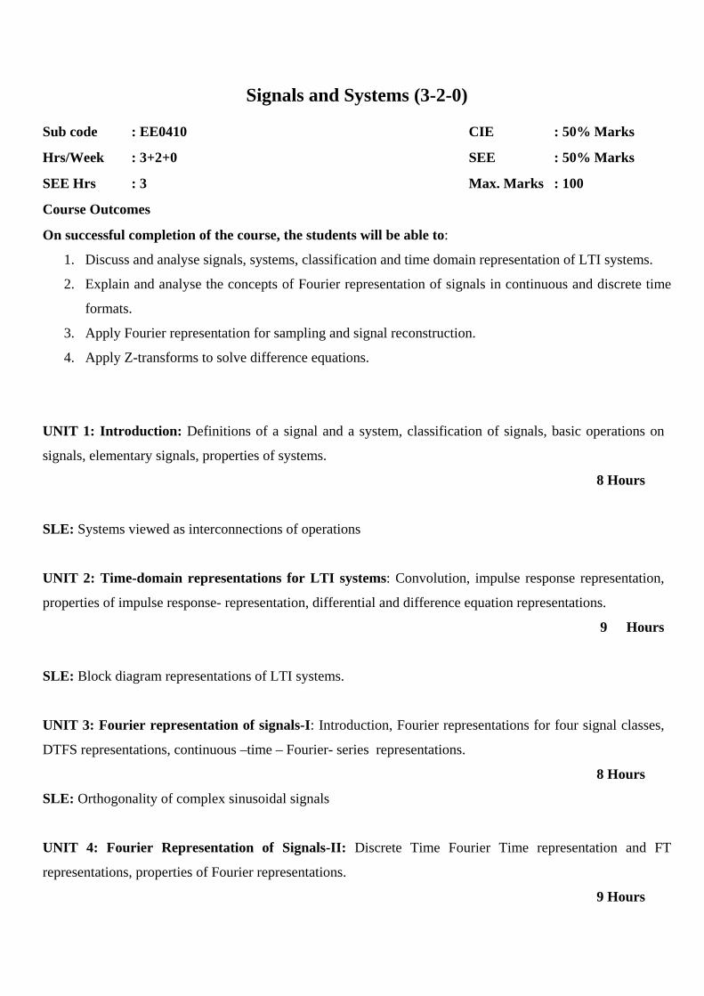
Signals and Systems (3-2-0)
Sub code : EE0410 CIE : 50% Marks
Hrs/Week : 3+2+0 SEE : 50% Marks
SEE Hrs : 3 Max. Marks : 100
Course Outcomes
On successful completion of the course, the students will be able to:
1. Discuss and analyse signals, systems, classification and time domain representation of LTI systems.
2. Explain and analyse the concepts of Fourier representation of signals in continuous and discrete time
formats.
3. Apply Fourier representation for sampling and signal reconstruction.
4. Apply Z-transforms to solve difference equations.
UNIT 1: Introduction: Definitions of a signal and a system, classification of signals, basic operations on
signals, elementary signals, properties of systems.
8 Hours
SLE: Systems viewed as interconnections of operations
UNIT 2: Time-domain representations for LTI systems: Convolution, impulse response representation,
properties of impulse response- representation, differential and difference equation representations.
9 Hours
SLE: Block diagram representations of LTI systems.
UNIT 3: Fourier representation of signals-I: Introduction, Fourier representations for four signal classes,
DTFS representations, continuous –time – Fourier- series representations.
8 Hours
SLE: Orthogonality of complex sinusoidal signals
UNIT 4: Fourier Representation of Signals-II: Discrete Time Fourier Time representation and FT
representations, properties of Fourier representations.
9 Hours
SLE: Algorithms for FT and DFT
UNIT 5: Application of Fourier Representations: Frequency response of LTI systems, solution of
differential and difference equations using system function, Sampling of continuous time signals and signal
reconstruction. 9 Hours
SLE: Fourier transform representations for periodic signals .
UNIT 6: Z-Transforms: Introduction, Z-transform, properties of ROC, properties of Z-transforms, Inverse
Z-transforms, transforms analysis of LTI systems, transfer function, Stability and causality, unilateral Z-
transform and its application to solve difference equations.
9 Hours
SLE: Z-Transform Realization of system function
Text Book:
1. Simon Haykin and Bary Van Veen,“Signals and Systems”, John Wiley and Sons, 2008.
Reference Books:
1. Alan V Oppenheim, Alan S Wilskey and S. Hamid Movas, “Signals and Systems”, 2nd edition 1997,
Indian Reprint 2002.
2. Michel J Roberts, “Signal and Systems: Analysis of Signals through Linear Systems”, Tata McGraw-Hill.
3. B. P. Lathi, “Linear Systems and Signals”, Oxford University Press, 2005
Open Courseware:
1. nptel.ac.in/courses/117104074/1
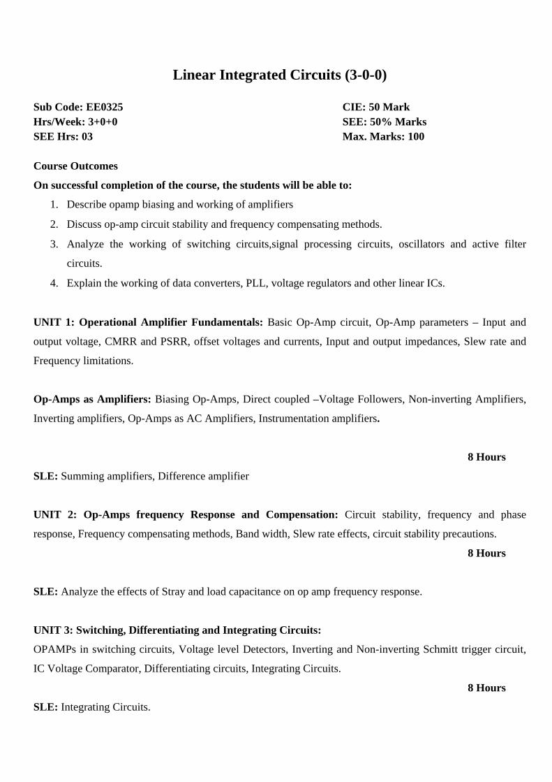
Linear Integrated Circuits (3-0-0)
Sub Code: EE0325 CIE: 50 Mark Hrs/Week: 3+0+0 SEE: 50% Marks SEE Hrs: 03 Max. Marks: 100 Course Outcomes
On successful completion of the course, the students will be able to:
1. Describe opamp biasing and working of amplifiers
2. Discuss op-amp circuit stability and frequency compensating methods.
3. Analyze the working of switching circuits,signal processing circuits, oscillators and active filter
circuits.
4. Explain the working of data converters, PLL, voltage regulators and other linear ICs.
UNIT 1: Operational Amplifier Fundamentals: Basic Op-Amp circuit, Op-Amp parameters – Input and
output voltage, CMRR and PSRR, offset voltages and currents, Input and output impedances, Slew rate and
Frequency limitations.
Op-Amps as Amplifiers: Biasing Op-Amps, Direct coupled –Voltage Followers, Non-inverting Amplifiers,
Inverting amplifiers, Op-Amps as AC Amplifiers, Instrumentation amplifiers.
8 Hours
SLE: Summing amplifiers, Difference amplifier
UNIT 2: Op-Amps frequency Response and Compensation: Circuit stability, frequency and phase
response, Frequency compensating methods, Band width, Slew rate effects, circuit stability precautions.
8 Hours
SLE: Analyze the effects of Stray and load capacitance on op amp frequency response.
UNIT 3: Switching, Differentiating and Integrating Circuits:
OPAMPs in switching circuits, Voltage level Detectors, Inverting and Non-inverting Schmitt trigger circuit,
IC Voltage Comparator, Differentiating circuits, Integrating Circuits.
8 Hours
SLE: Integrating Circuits.
UNIT 4: Signal Processing circuits and signal generators: Precision Half-wave rectifiers, Precision Full-
wave rectifiers, Limiting circuits, Clamping circuits, Peak detectors, Triangular wave generator, 555 timer
monostable, Timer pulse and square wave generators, Voltage controlled Oscillator, Delay timers, Sequential
timers, Phase shift oscillator, Wein bridge oscillator. 8 Hours
SLE: Pulse tone oscillator, 7555 CMOS timer
UNIT 5 : Non-linear circuit applications and Voltage Regulators: Active Filters –First and second order
Low pass and High pass filters, Band pass and Band rejection Filters
Voltage regulators: Introduction, Series Op-Amp regulator, IC Voltage regulators-723,LM317,LM337,
Switching Regulator operation, Comparison of linear and switching regulators.
8 Hours
SLE: Switching Regulators.
UNIT 6:
Data Converters and Phase locked loop (PLL):
Data Converters: R-2R DAC, Parallel ADC, Linear Ramp ADC, Dual slope Integrator ADC, Digital Ramp
ADC, Successive Approximation ADC.
Phase locked loop: Basic PLL system, PLL Components, PLL performance factors, Integrated Circuit PLL.
8 Hours
SLE: Multiplying DAC, Integrated circuit 8-bit DAC
Text Book:
1. David A. Bell,“Operational Amplifiers and Linear IC’s”,3rd edition, Oxford University Press, 2011
REFERENCE BOOKS:
1. Ramakanth Gayakwad, “OPAMPS and Linear Integrated Circuits”,4th edition, Prentice Hall, 1990.
2. Robert. F. Coughlin and Fred. F. Driscoll, “Operational Amplifiers and Linear Integrated Circuits”,
PHI/Pearson, 2006.

3. D. Roy Choudhury and Shail B. Jain, “Linear Integrated Circuits”,2nd edition, New Age International,
Reprint 2006.
Analog Electronics Lab (0-0-3)
Sub Code : EE0103 CIE : 25 Marks Hrs/Week : 0+0+3 SET : 25 Marks Course Outcomes
On successful completion of the course, the students will be able to:
1.Design, simulate and test analog electronics circuits for wave shaping and amplification.
2. Design, simulate and test opamp based amplifiers, wave shaping circuits, rectifiers,
multivibrators and filters.
3. Demonstrate the working of different types of oscillators and Digital to Analog
Converters.
List of Experiments:
1. Design, Simulation and testing of diode clipping circuits.
2. Design, Simulation and testing of diode clamping circuits.
3. Design, Simulate and test RC coupled amplifier and plot the frequency response
characteristics.
4. Design, Simulate and test JFET/MOSFET amplifier and plot the frequency response
characteristics.
5. Study of RC phase shift, Hartley and Colpitts oscillator.
6. Design, Simulation and testing of op-amp inverting and non-inverting amplifier.
7. Design, Simulation and testing of op-amp integrator and differentiator.
8. Design, Simulation and testing of precision half wave and full wave rectifiers using op-amps.
9. Design, Simulation and testing of op-amp Schmitt trigger circuits.
10. Simulation and testing of R-2R DAC using op-amps.
11. Design, Simulation and testing of Astable and Monostable multivibrator using 555 timer IC.
12. Design of I- order and II-order filters using op-amps.
Electrical Machines Lab-I (0-0-3)
Sub Code : EE0104 CIE : 25 Marks Hrs/Week : 0+0+3 SET : 25 Marks Course Outcomes
On successful completion of the course, the students will be able to:
1. Conduct the load test on DC motor to determine their characteristics.
2. Conduct experiments on different methods of Speed control of DC motor.
3. Determine the performance indices of DC machines and transformers.
4. Predetermine efficiency and regulation of single phase transformers.
5. Study the operation of two dissimilar transformers connected in parallel.
List of Experiments:
1. Load test on a DC Motor – determination of speed-torque and BHP – efficiency Characteristics.
2. Speed Control of DC motor by Armature Voltage Control and Flux control.
3. Swinburne’s test.
4. Ward Leonard method of speed control of D.C. motor
5. Hopkinson’s Test.
6. Field test on series motors.
7. Retardation test – electrical braking method.
8. SC, OC test on single phase transformer and predetermination of efficiency and regulation and
verification by direct loading for UPF.
9. Sumpner’s test.
10. Parallel operation of two dissimilar single phase transformers.
11. Scott connection for balanced and unbalanced two phase UPF loads.
12. Three-phase transformer connections.