beam diagnostic requirements overview
TRANSCRIPT

Beam Diagnostic Requirements Overview
Gero KubeDESY (Hamburg)
� Measurement Principles
� Specific Diagnostics Needs for Hadron Accelerators
� Specific Diagnostics Needs for Electron Accelerators
Beam Instrumentation CAS, Tuusula (Finland), 2-15 Ju ne 2018

Reminder: Lepton Properties
properties of electrons/positrons
simple point objects
small rest mass
…discussion in context with different accelerator types
consequences
particles are relativistic already at a few MeV
→ typically at first accelerating section 0 50 100 150 200 250 300 350 400 450 5000
0.1
0.2
0.3
0.4
0.5
0.6
0.7
0.8
0.9
1
Ekin
[MeV]
ββ ββ =
v/c
electron
Gero Kube, DESY / MDI Beam Instrumentation CAS, Tuusula (Finland), 2-15 June 2018
���� � 0.511MeV
→ long range of transverse non-propagating fields
→ emission of synchrotron radiation (bend motion)
particle produce strong electromagnetic field
-0.05 0 0.050
1
2
3
4x 10
-12
time [psec]
Ex [V
/m]
∆t ~ 1/γ
Amplitude ~ γ
non-propagating transverse el. field
Lorentz factor: � �/����
influence on particle dynamics
impact on beam diagnostics
Electron Collider
� Comments on Synchrotron Radiation
� Injector Chain
� Storage Ring
The CERN Accelerator School
Tuusula (Finland), 2-15 June 2018

Lepton Collider (Storage Ring)
LEP @ CERN100 GeV e+/e-
HERA @ DESY27.5 GeV e+(e-) / 920 GeV p
general comments on lepton colliders (storage rings)
standard, normal conducting dipole magnets
→ sufficient to achieve final energies
long injector chain with different beam properties
→ relaxed requirements, particle dynamics with radiation
Gero Kube, DESY / MDI Beam Instrumentation CAS, Tuusula (Finland), 2-15 June 2018
Super KEKB @ KEK (Tsukuba)4 GeV e+/ 7 GeV e-
BEBC II @ IHEP (Beijing)1 - 2.1 GeV e+/e-
first collisions: 26th April 2018

SR Emission in circular Acceleratorsemitted power power is real!
damaged front end gate valve;incident power about 1 kW for time estimated to 2-10 min.
protect accelerator components from
direct SR illumination !
L.R
ivki
n(P
SI)
, CA
S 2
004
Gero Kube, DESY / MDI Beam Instrumentation CAS, Tuusula (Finland), 2-15 June 2018
�� MW � 8.85 � 10�� �� GeV�� m � A
HERA e(I=50 mA, E=27.5 GeV, ρ=550 m): Pγ= 4.6 MW
energy loss per turn
→ average radiated power restored by RF
cavity provides voltage to accelerate particles back to nominal energy
∆� keV � 88.5 �� GeV�� m
HERA e(E=27.5 GeV): ∆E = 92 MeV
HERA e: 98 cavities, grouped in 8 sections;8 transmitter stations, each with 1.4 MW nominal power, fed by 2 Klystrons.requires typically a large number of cavities

Consequences of SR Emissionlarge number of cavities
cavity representshigh impedance → excitation of (multibunch) instabilities
Gero Kube, DESY / MDI Beam Instrumentation CAS, Tuusula (Finland), 2-15 June 2018
need for feedback systems
high SR power
heat load critical protection of machine and instrumentation, necessity of cooling
high total cavity voltageVr for loss compensation & lifetime
rms bunch length (above transition energy)� � !" # 1/ �2%&' �( ∝ 1
*+,smaller bunch lengths→ beam spectrum with higher frequencies
beam emittance
formation ofequilibrium emittancesin all 3 planes
→ radiation dampingandquantum fluctuations(random excitation of oscillations)
emittance determined by storage ring itself
emittance blow-up not critical, relaxed requirements for injector chain

e± Injector Complex @ DESY
e±±±±
e±±±±450 MeV
Linac front-end
3 GHz Linac section
• thermionic gun
150 keV, 3 µsec long pulses @ 50 Hz
• chopper and collimator
shortening of long gun pulses (60/20 nsec for e+/e-)
• pre-buncher
single cell cavity, matching to linac RF
• Linac sections
3 GHz (S-band) travelling wave structure, frep = 50 Hz
• converter for e+ production
7 mm (2 rad. length) thick W target in 1.8 T solenoid field
• Positron Intensity Accumulator (PIA)
re-formation of time structure for synchrotrons (→ 500 MHz)
two RF systems (10.4 MHz and 125 MHz)
e-solenoid lenses
Gero Kube, DESY / MDI Beam Instrumentation CAS, Tuusula (Finland), 2-15 June 2018

Injector Complex Instrumentationkey devices for
transfer efficiency
→ current transformers
beam position for beam steering
→ screens (low energy deposition)
→ BPMs (sensitivity for long linac bunch trains)
beam profiles for beam optics matching
→ scintillating/OTR screens (in straight section)
→ synchrotron light (accumulator ring)
transverse emittance
→ multi-screen method or quadrupole scans
(in straight section)
→ synchrotron light (accumulator ring)
longitudinal plane
→ magnet spectrometer for energy (-spread)
(diagnostics beamline)
→ time structure via RF deflector, wall
current monitor, coh. radiation diagnostics
overview: standard instrumentation and their tasks
Gero Kube, DESY / MDI Beam Instrumentation CAS, Tuusula (Finland), 2-15 June 2018
adjusting beam transport through injector sections
tuning the RF system
indicating operating status
matching the energy acceptance (∆E/E) of accumulator ring
→ i) spread from conversion process, ii) microbunch length
→ precise measurements of energy spread and bunch length
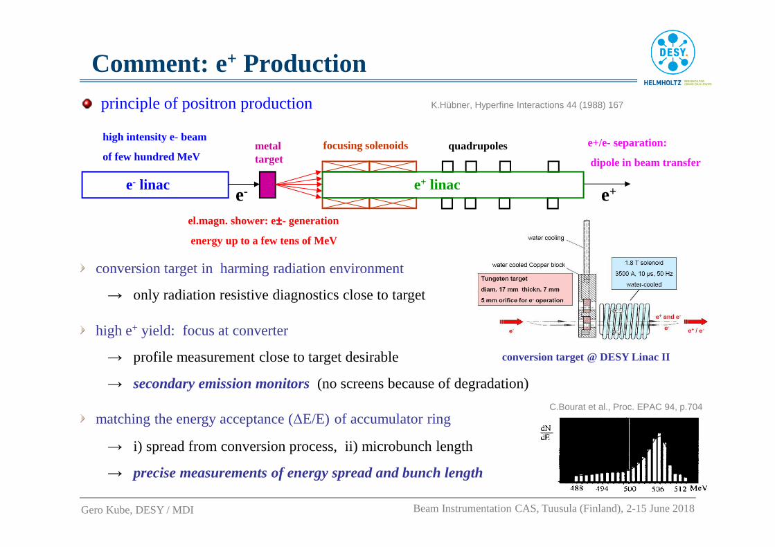
C.Bourat et al., Proc. EPAC 94, p.704
conversion target @ DESY Linac II
Comment: e+ Productionprinciple of positron production K.Hübner, Hyperfine Interactions 44 (1988) 167
high intensity e- beam
of few hundred MeVmetal target
el.magn. shower: e±±±±- generation
energy up to a few tens of MeV
e- linac e+ linac
focusing solenoids quadrupoles
e- e+
e+/e- separation:
dipole in beam transfer
conversion target in harming radiation environment
→ only radiation resistive diagnostics close to target
high e+ yield: focus at converter
→ profile measurement close to target desirable
→ secondary emission monitors(no screens because of degradation)
Gero Kube, DESY / MDI Beam Instrumentation CAS, Tuusula (Finland), 2-15 June 2018
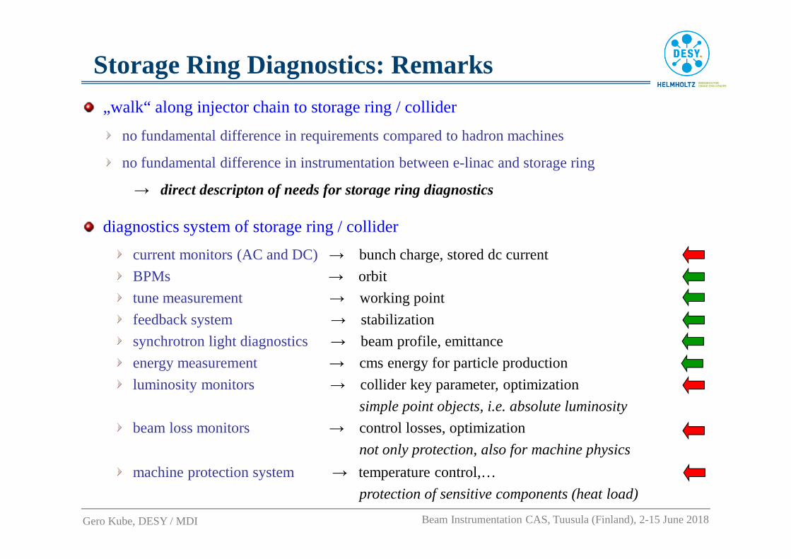
Storage Ring Diagnostics: Remarks
„walk“ along injector chain to storage ring / collider
no fundamental difference in requirements compared to hadron machines
no fundamental difference in instrumentation between e-linac and storage ring
→ direct descripton of needs for storage ring diagnostics
diagnostics system of storage ring / collider
current monitors (AC and DC) → bunch charge, stored dc current
BPMs → orbit
tune measurement → working point
feedback system → stabilization
synchrotron light diagnostics → beam profile, emittance
energy measurement → cms energy for particle production
luminosity monitors → collider key parameter, optimization
simple point objects, i.e. absolute luminosity
beam loss monitors → control losses, optimization
not only protection, also for machine physics
machine protection system → temperature control,…
protection of sensitive components (heat load)
Gero Kube, DESY / MDI Beam Instrumentation CAS, Tuusula (Finland), 2-15 June 2018

Storage Ring Diagnostics (1)
beam position monitors (BPMs)
short electron bunches(10 - 100 psec)
→ use ofbutton pickups
HERA e PEP II
synchrotron radiation emission
→ pickups mountedout of orbit plane
Gero Kube, DESY / MDI Beam Instrumentation CAS, Tuusula (Finland), 2-15 June 2018
vacuum chamber profile not rotational-symmetric
→ horizontal emittance » vertical emittance
(SR emission in horizontal plane)
→ injection oscillations due to off-axis injection
(allows intensity accumulation)
-50 -40 -30 -20 -10 0 10 20 30 40 50-40
-30
-20
-10
0
10
20
30
40
mm
mm
Monitor Profile
-10 -8 -6 -4 -2 0 2 4 6 8 10-10
-8
-6
-4
-2
0
2
4
6
8
10
Horizontal Position [mm]
Ver
tica
l Po
sitio
n [m
m]
Position Map
correction of non-linearities
in beam position
Super KEKBH. Fukuma (KEK), Proc. eeFACT 2016, WET1H3

Storage Ring Diagnostics (2)tune radiation damping due to SR emission
→ permanent excitation, online tune control
HERA etune controller
0p
KICKER
BAND-PASSFILTER
00 0p
BEAMPOSITIONMONITOR
AMPLITUDE
A
PHASE
NETWORKANALYZERHP 4195 A
RATIO B/A
RF OUT B
100 WCLASS A
100 WCLASS A
H. Fukuma (KEK), Proc. eeFACT 2016, WET1H3
feedbacklong-range electromagnetic fields and short bunch lengths (→ broad beam spectrum)
→ fields act back on beam itself via environment
→ excitation ofcoupled bunch instability
feedback system for instability damping
i) detection system to measure beam oscillations
ii) signal processing unit to derive correction signal
iii) broad band amplifier and beam deflector to act on beam
courtesy: F.Sannibale(LBNL)
Gero Kube, DESY / MDI Beam Instrumentation CAS, Tuusula (Finland), 2-15 June 2018
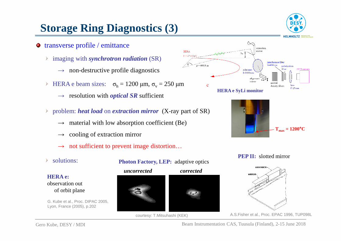
Storage Ring Diagnostics (3)transverse profile / emittance
imaging withsynchrotron radiation(SR)
→ non-destructive profile diagnostics
HERA e SyLi monitorHERA e beam sizes:σh = 1200 µm, σv = 250 µm
→ resolution withoptical SRsufficient
problem: heat loadon extraction mirror (X-ray part of SR)
→ material with low absorption coefficient (Be)
→ cooling of extraction mirror
→ not sufficient to prevent image distortion…
Tmax = 1200°°°°C
Gero Kube, DESY / MDI Beam Instrumentation CAS, Tuusula (Finland), 2-15 June 2018
solutions:
A.S.Fisher et al., Proc. EPAC 1996, TUP098L
PEP II: slotted mirrorPhoton Factory, LEP: adaptive optics
courtesy: T.Mitsuhashi (KEK)
uncorrected correctedHERA e: observation out
of orbit plane
G. Kube et al., Proc. DIPAC 2005, Lyon, France (2005), p.202

Storage Ring Diagnostics (4)longitudinal profile
SR single particle time structure
→ calculation for 6 GeV electron,
electric field vector in orbit plane
time structure of SR suitable
to resolvepseclongitudinal
profiles (and even less)
Gero Kube, DESY / MDI Beam Instrumentation CAS, Tuusula (Finland), 2-15 June 2018
Δt � 2/ω0 =4ρ3γ5c
#1 ω0⁄ 81 ω0⁄
streak camera
→ time resolution ~ 1 psec
courtesy: Hamamatsu
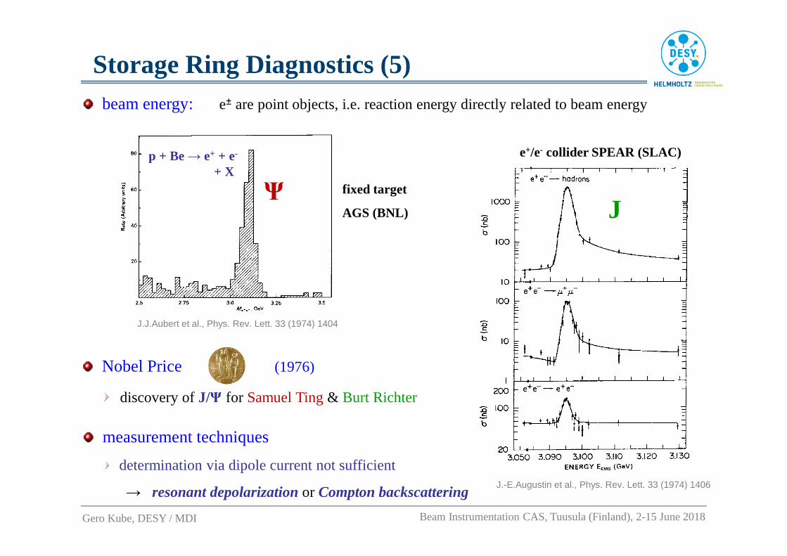
Storage Ring Diagnostics (5)
J.-E.Augustin et al., Phys. Rev. Lett. 33 (1974) 1406
J
e+/e- collider SPEAR (SLAC)
J.J.Aubert et al., Phys. Rev. Lett. 33 (1974) 1404
p + Be → e+ + e-
+ X
Ψ fixed target
AGS (BNL)
beam energy: e± are point objects, i.e. reaction energy directly relatedto beam energy
Gero Kube, DESY / MDI Beam Instrumentation CAS, Tuusula (Finland), 2-15 June 2018
discovery ofJ/Ψ for Samuel Ting & Burt Richter
(1976)Nobel Price
determination via dipole current not sufficient
→ resonant depolarizationor Compton backscattering
measurement techniques

3rd Generation Light Source
� Storage Ring based Light Source
The CERN Accelerator School
Tuusula (Finland), 2-15 June 2018
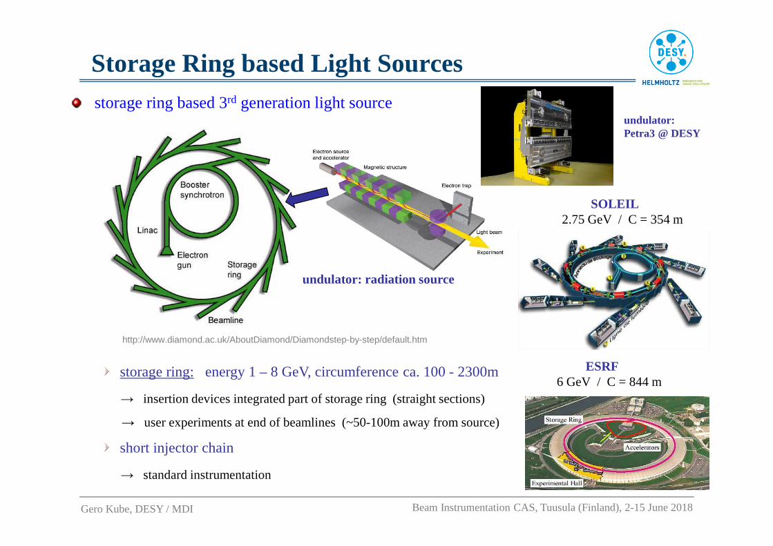
Storage Ring based Light Sources
ESRF6 GeV / C = 844 m
SOLEIL2.75 GeV / C = 354 m
storage ring based 3rd generation light source
storage ring: energy 1 – 8 GeV, circumference ca. 100 - 2300m
→ insertion devices integrated part of storage ring (straight sections)
→ user experiments at end of beamlines (~50-100m away from source)
short injector chain
→ standard instrumentation
http://www.diamond.ac.uk/AboutDiamond/Diamondstep-by-step/default.htm
undulator:Petra3 @ DESY
undulator: radiation source
Gero Kube, DESY / MDI Beam Instrumentation CAS, Tuusula (Finland), 2-15 June 2018
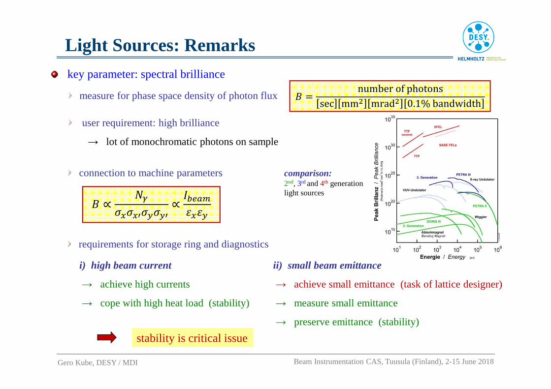
Light Sources: Remarks
key parameter: spectral brilliance
measure for phase space density of photon flux
i) high beam current
→ achieve high currents
→ cope with high heat load (stability)
requirements for storage ring and diagnostics
ii) small beam emittance
→ achieve small emittance (task of lattice designer)
→ measure small emittance
→ preserve emittance (stability)
Gero Kube, DESY / MDI Beam Instrumentation CAS, Tuusula (Finland), 2-15 June 2018
user requirement: high brilliance
→ lot of monochromatic photons on sample
comparison:2nd, 3rd and 4th generationlight sources
9 � numberofphotonssec mm� mrad� 0.1%bandwidth
connection to machine parameters
9 ∝ H��I�IJ�K�KJ ∝
�L�MNOIOK
stability is critical issue

Light Sources: Stabilityenergy stability, suppression of energy widening effects
cause: (long.) multibunch instabilities
shift of radiation harmonics from undulator
→ intensity fluctuation, line broadening
longitudinal multibunch feedback systems (MBFS)
intensity stability
change in background conditions and thermal load on beamline and machine components
→ position stability!
transverse multibunch instabilities→ transverse MBFS
position stability
intensity fluctuations, emittance dilution→ reduction of brilliance
orbit feedback systemsincludinghigh resolution e-BPMs andphoton-BPMs in beamlines
stored current (1 week) @ Spring8
H.Tanaka et al., J. Synchrotron Rad. 13 (2006) 378
top-up no top-up
operation in top-up mode(passive stabilization)
→ loss compensation by refill small amount of
charges in short time intervals
vast dynamic range for instruments, starting from injector chain
Gero Kube, DESY / MDI Beam Instrumentation CAS, Tuusula (Finland), 2-15 June 2018
undulator radiation (3rd harmonic) @ ALS
Synchrotron Radiation
Sources – A Primer, ed. H.Winick

Light Sources: BPMs
high resolution e-BPMs
typical stability tolerance: 20% emittance growth → l0% of the (1σ) beam size
→ example: averageposition stability at IDs for PETRA III @ DESY ∆σhor = 2 µm, ∆σvert = 0.3 µm
photon BPM
location in user beamlines: two monitors (per plane) → correction of position and angle
∆∆∆∆y
e-
e-
SR
Beam
“Blades”
„blade“ type BPM
sensitive for tails
of distribution
courtesy: F.Sannibale (LBNL)
residual gas XBPM
sensitive also for
distribution core
courtesy: P.Ilinski (BNL)
Gero Kube, DESY / MDI Beam Instrumentation CAS, Tuusula (Finland), 2-15 June 2018
∆εε � 2∆�
�
S. Sharma et al., Proc. MEDSI-6 2011, DLS Proceedings Vol. 1 e63
typical example: NSLS-II BPM chamber
→ asymmetric chamber profiles
(pumping channel, avoid heat load, …)
correction of strong positionnon-linearities

emittance:
example: σh = 40 µm, σv = 20 µm (PETRA III @ DESY)
typical values εx = 1-5 nm.rad and 1% emittance coupling
fundamental resolution limit (uncertainty principle)
imaging at smaller wavelengths: X-ray imaging with focusing optics
reflective optics diffractive optics refractive optics
Kirkpatrick-Baez mirrors,… Fresnel zone plates,… Compound Refractive Lenses (CRL)
F. Ewald et al., Proc. IBIC 2013, Oxford, UK (2013) 833
CRL monitor @ ESRF (32 keV)
X-ray imaging with non-focusing optics
pinhole camera C. Thomas et al., Phys. Rev. ST Accel. Beams 13 (2010) 022805example: Diamond Light Source
Light Sources: Emittance Diagnostics (1)
Gero Kube, DESY / MDI Beam Instrumentation CAS, Tuusula (Finland), 2-15 June 2018
∆� Q R2∆Ψ
λ = 500 nmand ∆Ψv = 1.7 mradoptical imaging @ PETRA: diffraction limited∆�T � 145μm
detectorspatial resolving
lens
e
λ
∆Ψ∆σ

exploit coherence properties
T. Mitsuhashi, Proc. of BIW 2004 Knoxville, Tennessee, p.3
Light Sources: Emittance Diagnostics (2)
Gero Kube, DESY / MDI Beam Instrumentation CAS, Tuusula (Finland), 2-15 June 2018
double slit
signal on CCD
Synchrotron Radiation Interferometer (SRI)
εx = 160 pm.rad @ 3 GeV
USR studies at PETRA III (DESY):
example: SRI @ PETRA III
coded aperture imaging
R.H. Dicke, Astrophys. Journal 153, L101, (1968)
J.W. Flanagan et al., Proc. DIPAC 2011, Hamburg, Germany (2011) 561
C. Bloomer, „Coded Aperture @ DLS“, TUCZB2
V. Schlott et al., Proc. IBIC 2013, Oxford, UK (2013) 519
widely applied @ SLS
exploit Point Spread Function (PSF)
π-polarization imaging
4th Generation Light Source
� Linac based Light Source
→ Free Electron Laser (FEL)
The CERN Accelerator School
Tuusula (Finland), 2-15 June 2018
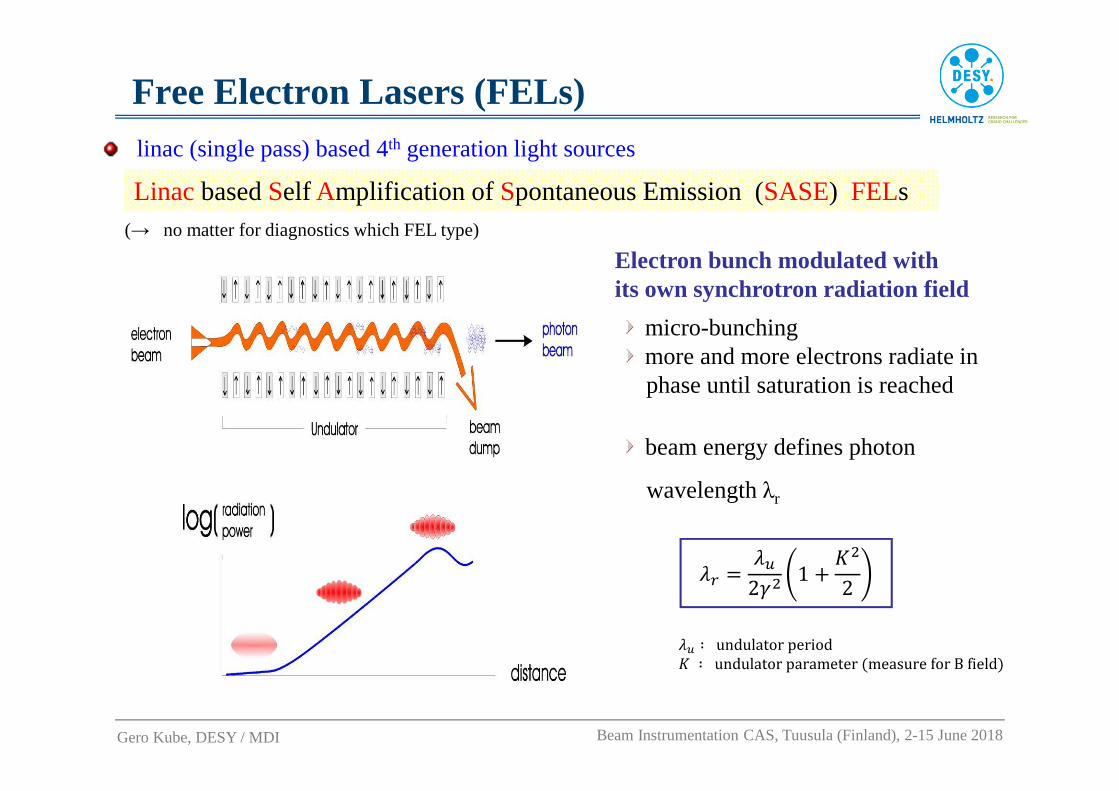
Free Electron Lasers (FELs)linac (single pass) based 4th generation light sources
Linacbased Self Amplification of Spontaneous Emission (SASE) FELs
Electron bunch modulated with its own synchrotron radiation field
micro-bunchingmore and more electrons radiate in phase until saturation is reached
(→ no matter for diagnostics which FEL type)
Gero Kube, DESY / MDI Beam Instrumentation CAS, Tuusula (Finland), 2-15 June 2018
beam energy defines photon
wavelengthλr
R+ � RV2 � 1 8 W�
2
RV ∶ undulatorperiodW ∶ undulatorparameterZmeasureforBfield\

Free Electron Lasers (FELs)linac-based European X-ray FELs
Gero Kube, DESY / MDI Beam Instrumentation CAS, Tuusula (Finland), 2-15 June 2018
FLASH @ DESY (Hamburg)Emax = 1.25 GeV, λ = 4 – 90 nm
Th. Tschentscher et al., Appl. Sci. 2017, 7(6), 592
European XFEL @ XFEL GmbH/DESY (Hamburg)Emax = 17.5 GeV, λ = 0.05 – 4.7 nm
SwissFEL @ PSI (Villigen)Emax = 5.8 GeV, λ = 0.1 – 5 nm
FERMI @ Elettra (Trieste)Emax = 1.5 GeV, λ = 4 – 65 nm
seeded FEL (no SASE)
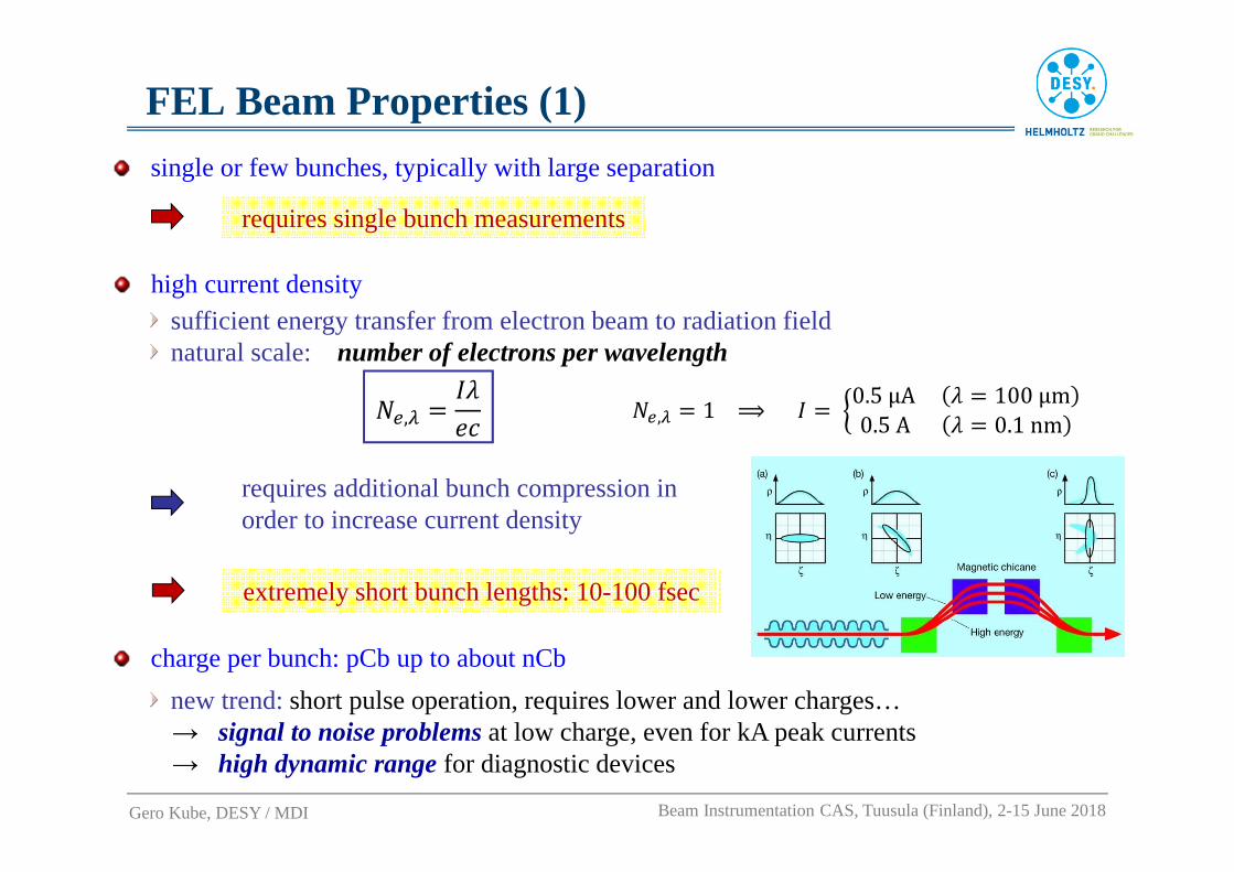
single or few bunches, typically with large separation
charge per bunch: pCb up to about nCb
new trend: short pulse operation, requires lower and lower charges…→ signal to noise problems at low charge, even for kA peak currents→ high dynamic range for diagnostic devices
FEL Beam Properties (1)
Gero Kube, DESY / MDI Beam Instrumentation CAS, Tuusula (Finland), 2-15 June 2018
requires single bunch measurements
high current densitysufficient energy transfer from electron beam to radiation fieldnatural scale: number of electrons per wavelength
H�,^ � 1 ⟹ � � `0.5μA R � 100μm0.5A R � 0.1nmH�,^ � �R
a�
extremely short bunch lengths: 10-100 fsec
requires additional bunch compression in order to increase current density
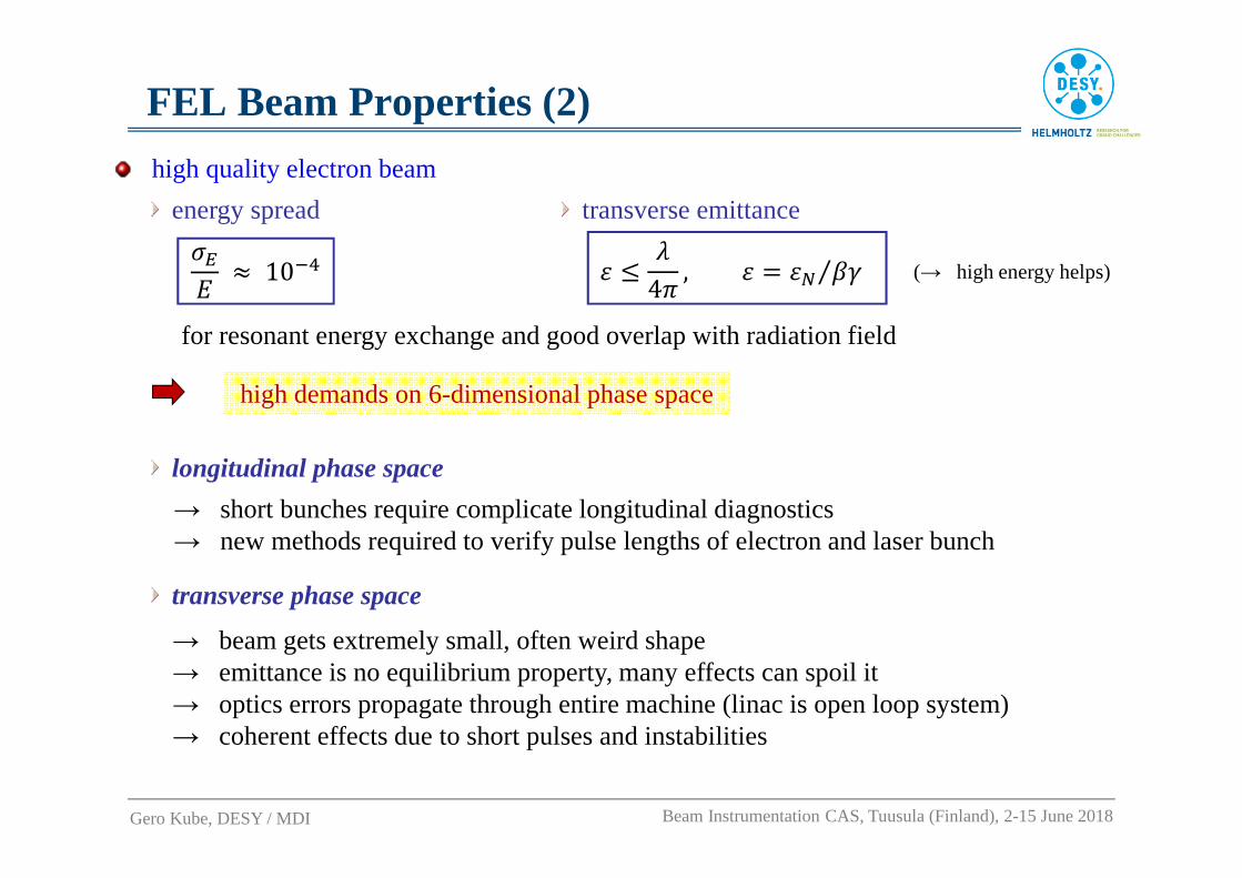
high quality electron beam
energy spread
for resonant energy exchange and good overlap with radiation field
transverse emittance
(→ high energy helps)
FEL Beam Properties (2)
Gero Kube, DESY / MDI Beam Instrumentation CAS, Tuusula (Finland), 2-15 June 2018
�b� Q 10�� O c R
4% , O � Od e ⁄
high demands on 6-dimensional phase space
→ short bunches require complicate longitudinal diagnostics→ new methods required to verify pulse lengths of electron and laser bunch
longitudinal phase space
→ beam gets extremely small, often weird shape→ emittance is no equilibrium property, many effects can spoil it→ optics errors propagate through entire machine (linac is open loop system)→ coherent effects due to short pulses and instabilities
transverse phase space
x
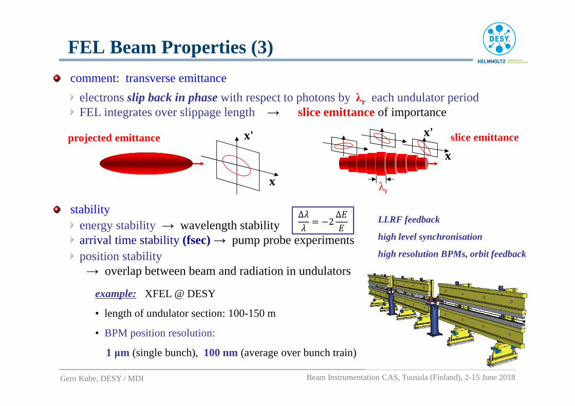
x'
λr
slice emittance
x
x'projected emittance
LLRF feedback
high level synchronisation
high resolution BPMs, orbit feedback
FEL Beam Properties (3)
Gero Kube, DESY / MDI Beam Instrumentation CAS, Tuusula (Finland), 2-15 June 2018
comment: transverse emittance
electrons slip back in phase with respect to photons byλr each undulator periodFEL integrates over slippage length → slice emittanceof importance
stabilityenergy stability→ wavelength stability arrival time stability (fsec) → pump probe experiments
example: XFEL @ DESY
• length of undulator section: 100-150 m
• BPM position resolution:
1 µm (single bunch),100 nm(average over bunch train)
position stability→ overlap between beam and radiation in undulators
∆RR � #2∆�
�

FELs: Commentslinac-based FEL
no radiation damping → beam quality determined already from the gun
SASE FEL is not forgiving – instead of reduced brightness, power nearly switchesOFF
Gero Kube, DESY / MDI Beam Instrumentation CAS, Tuusula (Finland), 2-15 June 2018
careful diagnostics and control of beam parameters
accelerating structures part of SASE FELs use superconducting RF cavities
9 cell, 1.3 GHz Nb TESLA cavity
part of diagnostics (BPMs) in cold vacuum
particle free environment
SASE FELs: FLASH and XFEL @ DESY

FEL Diagnostics: Overviewstandard electron beam diagnostics to operate the linac
electron beam orbitbunch chargebeam size
beam phaseenergy and energy spread
instrumentation to measure
prevent damage onundulator(demagnetization) and vacuum system(leakage)fast protection system to shut-off the beam in case of high losses
diagnostics needed to control and optimize the FEL
beam size / transverse emittance→ OTR/wire-scanner stations, resolution < 10 µm
bunch length / longitudinal profile→ bunch length < 100 fsec, reconstruction of bunch shape
slice emittancebunch compression→ online signal for optimization of SASE process
diagnostics needed for user experiments
characterization of radiation pulse (energy, spectral distribution) synchronisation & stability (time-resolved experiments → fsec)
Gero Kube, DESY / MDI Beam Instrumentation CAS, Tuusula (Finland), 2-15 June 2018
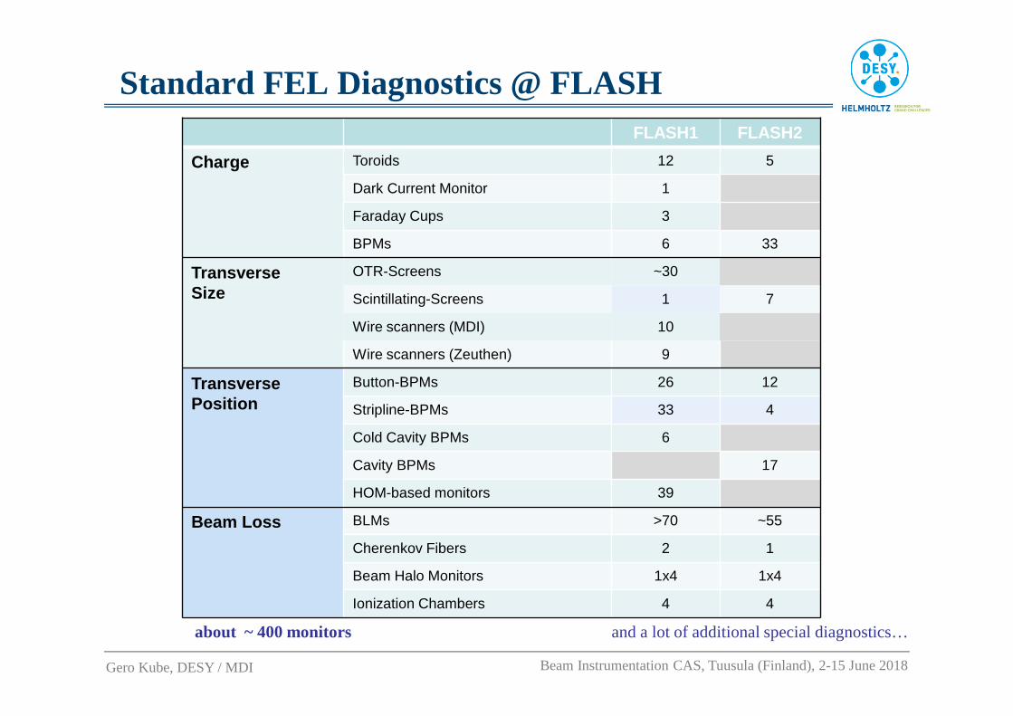
Standard FEL Diagnostics @ FLASH
and a lot of additional special diagnostics…
FLASH1 FLASH2
Charge Toroids 12 5
Dark Current Monitor 1
Faraday Cups 3
BPMs 6 33
Transverse Size
OTR-Screens ~30
Scintillating-Screens 1 7
Wire scanners (MDI) 10
Wire scanners (Zeuthen) 9
Transverse Position
Button-BPMs 26 12
Stripline-BPMs 33 4
Cold Cavity BPMs 6
Cavity BPMs 17
HOM-based monitors 39
Beam Loss BLMs >70 ~55
Cherenkov Fibers 2 1
Beam Halo Monitors 1x4 1x4
Ionization Chambers 4 4
about ~ 400 monitors
Gero Kube, DESY / MDI Beam Instrumentation CAS, Tuusula (Finland), 2-15 June 2018

Standard FEL Diagnostics @ E-XFEL
Monitor (Standard Diagnostics Only) Number
BPMs (cold) 120
BPMs (Striplines, Pickups) 250
Undulator BPMs (Cavity, 1µm Resolution)
140
Charge Monitors (Toroids, Faraday Cups)
40
Beam Size: OTR, Wirescanners
77
Dark Current 10
Loss Monitors (PM Systems, Fibers)
320
Phase 15
Other about 50
Total about 1000
and a lot of additional special diagnostics…
Gero Kube, DESY / MDI Beam Instrumentation CAS, Tuusula (Finland), 2-15 June 2018

Num
ber
Bea
m P
ipe
Leng
th
Type
Sin
gle
Bun
ch
Res
olut
ion
(RM
S)
Trai
n A
vera
ged
Res
olut
ion
(R
MS
)
Opt
imum
R
esol
utio
nR
ange
Rel
axed
R
esol
utio
n R
ange
x/y
Cro
ssta
lk
Bun
ch to
Bun
ch
Cro
ssta
lk
Tran
s. A
lignm
ent
Tole
ranc
e (R
MS
)
mm mm µm µm mm mm % µm µmStandard BPM 219 40.5 200/
100Button 50 10 ± 3.0 ± 10 1 10 200
Cold BPM 102 78 170 Button/Re-entrant
50 10 ± 3.0 ± 10 1 10 300
Cavity BPM Beam Transfer Line
12 40.5 255 Cavity 10 1 ± 1.0 ± 2 1 1 200
Cavity BPM Undulator
117 10 100 Cavity 1 0.1 ± 0.5 ± 2 1 0.1 50
IBFB 4 40.5 255 Cavity 1 0.1 ± 1.0 ± 2 1 0.1 200
Beam Position Monitors
short version of E-XFEL BPM specification
specified charge range: 0.1 – 1nC
courtesy: D.Nölle (DESY)different BPM types to meet different requirements
Gero Kube, DESY / MDI Beam Instrumentation CAS, Tuusula (Finland), 2-15 June 2018

Transverse Beam Profile: Coherent Effectsstandard beam diagnostics: Optical Transition Radiation (OTR)
courtesy:
K. Honkavaara (DESY)
backward OTR: reflection of virtual photons
→ instantaneous process
single shot measurement
full transverse (2D) profile information
Coherent OTR observation at LCLS (SLAC)
R. Akre et al., Phys. Rev. ST Accel. Beams11 (2008) 030703
H. Loos et al., Proc. FEL 2008, Gyeongju, Korea, p.485.
20 40 60
20
40
6020 40 60
20
40
6020 40 60
20
40
60
20 40 60
20
40
6020 40 60
20
40
6020 40 60
20
40
60
OTR 12 OTR 22
strong shot-to-shot fluctuations
doughnut structure
change of spectral contentsmeasured spot is no beam image!
E.L. Saldin et al., NIM A483 (2002) 516 Z. Huang and K. Kim, Phys. Rev. ST Accel. Beams5 (2002) 074401
interpretation of coherent formation in terms of “Microbunching Instability”
alternative schemes for beam profile diagnostics
wire scanners → bunch trains
Gero Kube, DESY / MDI Beam Instrumentation CAS, Tuusula (Finland), 2-15 June 2018
scintillating screens → single shot
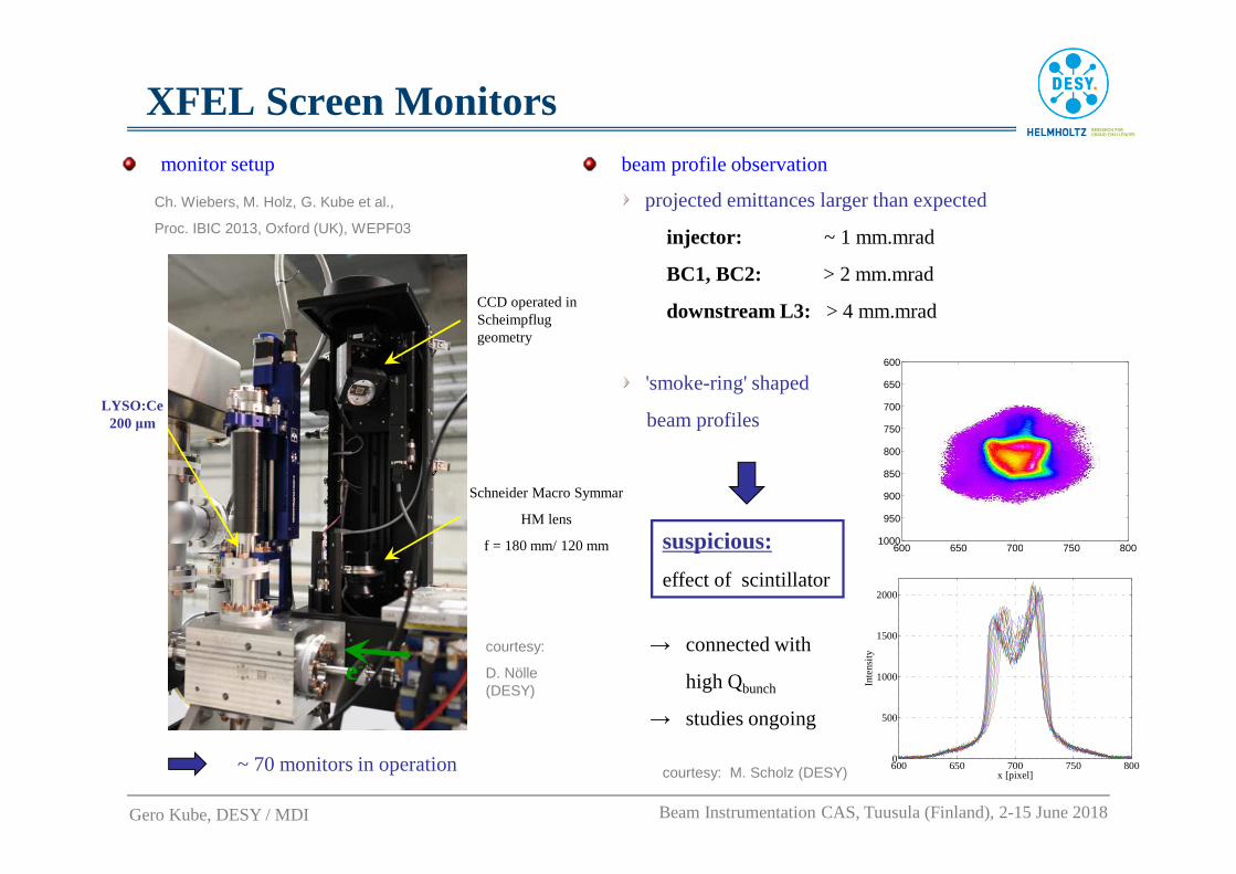
XFEL Screen Monitors
e-courtesy:
D. Nölle (DESY)
Ch. Wiebers, M. Holz, G. Kube et al.,
Proc. IBIC 2013, Oxford (UK), WEPF03
~ 70 monitors in operation
monitor setup
Gero Kube, DESY / MDI Beam Instrumentation CAS, Tuusula (Finland), 2-15 June 2018
Schneider Macro Symmar
HM lens
f = 180 mm/ 120 mm
LYSO:Ce200 µm
CCD operated in Scheimpfluggeometry
beam profile observation
projected emittances larger than expected
injector: ~ 1 mm.mrad
BC1, BC2: > 2 mm.mrad
downstream L3: > 4 mm.mrad
600 650 700 750 800
600
650
700
750
800
850
900
950
1000
600 650 700 750 8000
500
1000
1500
2000
x [pixel]
Inte
nsity
'smoke-ring' shaped
beam profiles
courtesy: M. Scholz (DESY)
suspicious:
effect of scintillator
→ connected with
high Qbunch
→ studies ongoing

FEL Diagnostics: Bunch Length/Profilecoherent radiation diagnostics
principle: bunch length/shape dependent emission spectrum of coherent radiation
spectral decomposition and Fourier transform:→ bunch length and shape
bunch form factor
0 0.5 1 1.5 2 2.50
0.5
1
1.5
2
Frequency (THz)
Inte
nsity
(a.
u.)
-2 0 2 4
0
200
400
600
800
1000
Time (ps)
Ch
arg
e d
en
sit
y (
a.u
.)
Interferometer
Streak camera
Time (psec)
Cha
rge
Den
sity
(a.
u.)
source:synchrotron radiation, transition radiation, diffraction radiation, Smith-Purcell radiation,…
electro optical sampling (EOS)
principle: Coulomb field induces refractive index change in EO crystal(Pockels effect)→ effective polarization rotation proportional to Coulomb field
Coulomb field converted in opt. intensity variation→ laser + polarizer (P) + analyzer (A)
example:EOS using variable delay (simple scheme)more sophisticated: temporal, spectral, spatial encoding
cour
tesy
: B. S
teffe
n (
DE
SY
)co
urte
sy: O
.Grim
m(D
ES
Y)
with
single particle spectrum
no. of particles per bunch
( )2
1)()1(
dd
dd λ
λλFNNN
UU −+
=bunch profile∫= λ
πλ
zizSzF
2e)(d)(
Gero Kube, DESY / MDI Beam Instrumentation CAS, Tuusula (Finland), 2-15 June 2018

FEL Diagnostics: Slice Emittancetransverse deflecting structure (TDS)
0 0.5 1 1.50
10
20
ε xnorm
[mm
mra
d]
∆ t [ps]
∆ t [ps]
∆ x
[mm
]
0 0.5 1 1.5
-1
0
1
density profile [a.u.]slice boundaries
0
100
200
FLASH: slice emittance under SASE conditions @ 13.7 nm
image (rotated by 90°°°°) at OTR screen
courtesy: H. Schlarb (DESY)
horizontal size at imaging screen
→ access to slice emittances
'Intra Beam Streak Camera':
→ vertical deflecting RF structure
(2.856 GHz) operated at zero crossing
'parasitical' measurement using kicker and
off-axis screen
vertical sizeof beam at imaging screen
→ bunch length
Gero Kube, DESY / MDI Beam Instrumentation CAS, Tuusula (Finland), 2-15 June 2018

Outlook
� linear collider
� what is coming next…
The CERN Accelerator School
Tuusula (Finland), 2-15 June 2018

Outlookputting it all together…
injector linac, including e+ production
storage ring with opportunityof radiation damping
linacwith stringent requirements for 6-dimensional phase space
Gero Kube, DESY / MDI Beam Instrumentation CAS, Tuusula (Finland), 2-15 June 2018
…and build a linear collider:
https://www.linearcollider.org/pdf/ILC_Accelerator_bynumbers.pdf
superconducting RFL-band, 1.3 GHz Tesla-Technology
…or the CERN version:
CLIC layout 3 TeV
P.Burrows, CLIC Workshop 2016, CERN
normalconducting RFX-band, 12 GHz Technology

International Linear Colliderkey parameters (nominal values)
https://www.linearcollider.org/pdf/ILC_Accelerator_bynumbers.pdf
Gero Kube, DESY / MDI Beam Instrumentation CAS, Tuusula (Finland), 2-15 June 2018
challenges
beam position
→ measurement
→ stability
beam size
→ measurement
→ non-invasive
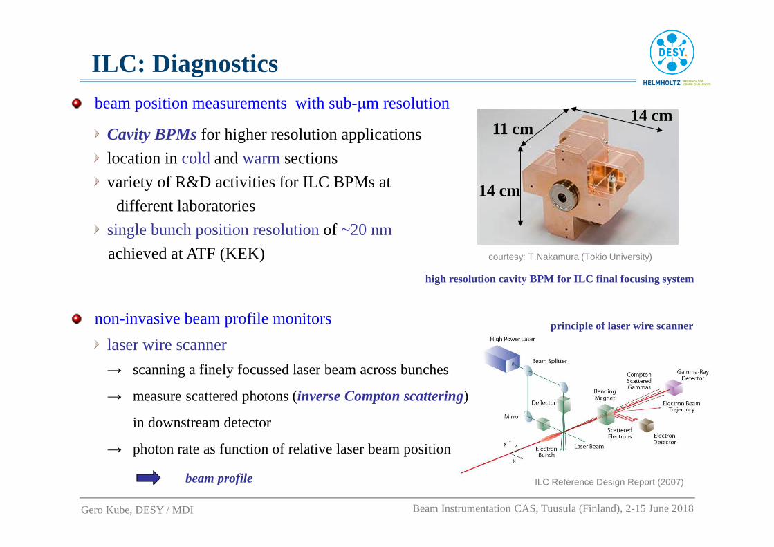
ILC: Diagnostics
high resolution cavity BPM for ILC final focusing system
beam position measurements with sub-µm resolution
Cavity BPMs for higher resolution applications
location in coldand warm sections
variety of R&D activities for ILC BPMs at
different laboratories
single bunch position resolution of ~20 nm
achieved at ATF (KEK)
Gero Kube, DESY / MDI Beam Instrumentation CAS, Tuusula (Finland), 2-15 June 2018
11 cm
14 cm
14 cm
courtesy: T.Nakamura (Tokio University)
principle of laser wire scannernon-invasive beam profile monitors
ILC Reference Design Report (2007)
laser wire scanner
→ scanning a finely focussed laser beam across bunches
→ measure scattered photons (inverse Compton scattering)
in downstream detector
→ photon rate as function of relative laser beam position
beam profile

Outlook: New Accelerators
https://fcc.web.cern.ch
Gero Kube, DESY / MDI Beam Instrumentation CAS, Tuusula (Finland), 2-15 June 2018
circular colliders
Future Circular Collider (FCC) @ CERN Circular e-e+ Collider (CEPC) @ China
(Super pp Collider - SppC)
Ebeam= 120 GeV, C = 54 km /100 km
light sources
circular: Ultra Low Emittance Rings
O ∝ �f5 → Multi Bend Achromat (MBA) scheme, i.e. small bend angle θ
challenging foremittance diagnostics
linear: from pulsedto cw operation
low chargeoperation forattosecond photon pulses
g
challenging forall diagnostics
plasma wakefield acceleration, dielectric wakefield acceleration, …
require new concepts for beam diagnostics