beam-section development · 2018-11-01 · 86 summer 2010 | pci journal development of the...
TRANSCRIPT

Summer 2010 | PCI Journal86
Development of the northeast extreme tee (NEXT) beam for accelerated bridge constructionMichael P. Culmo and Rita L. Seraderian
Adjacent-box-beam bridge systems have typically been the solution of choice for medium-span bridges in the northeast United States. However, the system does have limitations and has not worked well for all types of bridge replacements. In addition to the difficulty of accommodat-ing utilities across the width of the bridge, the box beam is more difficult to produce because it involves multiple steps. Field construction also has had issues with grouting procedures involving the shear keys.
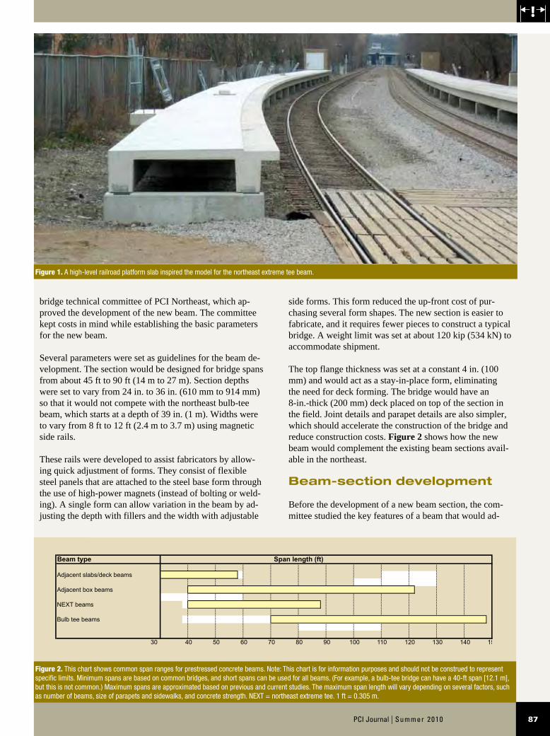
The idea for the northeast extreme tee (NEXT) beam oc-curred after one of the authors visited a precast concrete plant in September 2006 and noticed a precast concrete section that was developed for high-level railroad plat-forms (Fig. 1). This high-level-platform section, which was relatively short, had attributes that would work well for a medium-span highway bridge. Rotondo Precast in Rehoboth, Mass., developed the high-level-platform shape and provided the drawings of the section with some modi-fications to help with the early analysis.
Some quick calculations and parameters were set to deter-mine the feasibility of modifying this shape and moving it into the highway bridge market. Upon evaluation, the authors felt that this new section could provide the needed solutions for areas where box beams or deck slabs did not work well. The new section was proposed in concept to the
Editor’s quick points
n Adjacent box beams have uses, and limitations, for the highway bridge market.
n The northeast extreme tee (NEXT) beam provides solutions for applications where box beams or deck slabs do not work as well.
n Highlights of an actual use of the NEXT beam in the field are presented.
87PCI Journal | Summer 2010
side forms. This form reduced the up-front cost of pur-chasing several form shapes. The new section is easier to fabricate, and it requires fewer pieces to construct a typical bridge. A weight limit was set at about 120 kip (534 kN) to accommodate shipment.
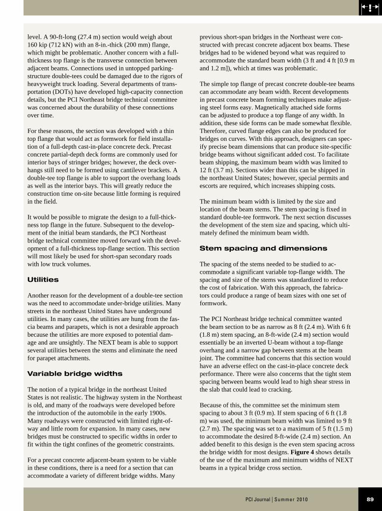
The top flange thickness was set at a constant 4 in. (100 mm) and would act as a stay-in-place form, eliminating the need for deck forming. The bridge would have an 8-in.-thick (200 mm) deck placed on top of the section in the field. Joint details and parapet details are also simpler, which should accelerate the construction of the bridge and reduce construction costs. Figure 2 shows how the new beam would complement the existing beam sections avail-able in the northeast.
Beam-section development
Before the development of a new beam section, the com-mittee studied the key features of a beam that would ad-
bridge technical committee of PCI Northeast, which ap-proved the development of the new beam. The committee kept costs in mind while establishing the basic parameters for the new beam.
Several parameters were set as guidelines for the beam de-velopment. The section would be designed for bridge spans from about 45 ft to 90 ft (14 m to 27 m). Section depths were set to vary from 24 in. to 36 in. (610 mm to 914 mm) so that it would not compete with the northeast bulb-tee beam, which starts at a depth of 39 in. (1 m). Widths were to vary from 8 ft to 12 ft (2.4 m to 3.7 m) using magnetic side rails.
These rails were developed to assist fabricators by allow-ing quick adjustment of forms. They consist of flexible steel panels that are attached to the steel base form through the use of high-power magnets (instead of bolting or weld-ing). A single form can allow variation in the beam by ad-justing the depth with fillers and the width with adjustable
Figure 1. A high-level railroad platform slab inspired the model for the northeast extreme tee beam.
Figure 2. This chart shows common span ranges for prestressed concrete beams. Note: This chart is for information purposes and should not be construed to represent specific limits. Minimum spans are based on common bridges, and short spans can be used for all beams. (For example, a bulb-tee bridge can have a 40-ft span [12.1 m], but this is not common.) Maximum spans are approximated based on previous and current studies. The maximum span length will vary depending on several factors, such as number of beams, size of parapets and sidewalks, and concrete strength. NEXT = northeast extreme tee. 1 ft = 0.305 m.
Beam type Span length (ft)
Adjacent slabs/deck beams
Adjacent box beams
NEXT beams
Bulb tee beams
30 40 50 60 70 80 90 100 110 120 130 140 150

Summer 2010 | PCI Journal88 88
were installed without topping, using the top flange as the vehicle-contact area. The PCI Northeast bridge technical committee determined that the top flange would need to be about 8 in. (200 mm) thick to accommodate truck loads and to provide adequate concrete cover.
Because of shipping and handling concerns, the commit-tee set a weight limit of 120 kip (534 kN) for the beam because it would be easy to obtain trucking permits at this
dress the goals of the new section. The following sections discuss the features that were studied and the conclusions reached by the committee. Figure 3 shows the final beam section. Table 1 shows the NEXT beam section properties.
General approach
Double-tee sections have been used for years in parking structures and on bridges. In some cases, the double-tees
Figure 3. This drawing illustrates the final beam dimensions. Note: A = beam width; B = beam depth; C = stem base width; Yb = distance from bottom of beam to center of gravity; Yt = distance from top of beam to center of gravity. 1 in. = 25.4 mm; 1 ft = 0.305 m.
Table 1. NEXT beam section properties
Beam designationBeam
width A, in.
Beam depth B,
in.
Base stem
width C, in.
Area, in.2 I , in.4 Yb , in. yt , in. sb , in.3 st , in.3 Weight, lb/ft
Minimum-width beams
NEXT 36 95.50 36.00 13.00 1287 160,240 21.77 14.23 11,261 7361 1341
NEXT 32 95.50 32.00 13.25 1182 115,813 19.51 12.49 9272 5936 1231
NEXT 28 95.50 28.00 13.50 1075 79,901 17.24 10.76 7426 4635 1120
NEXT 24 95.50 24.00 13.75 966 51,823 14.95 9.05 5726 3466 1006
Maximum-width beams
NEXT 36 143.50 36.00 13.00 1479 185,525 23.36 12.64 14,678 7942 1541
NEXT 32 143.50 32.00 13.25 1374 134,258 20.98 11.02 12,183 6399 1431
NEXT 28 143.50 28.00 13.50 1267 92,661 18.57 9.43 9826 4990 1320
NEXT 24 143.50 24.00 13.75 1158 60,045 16.12 7.88 7620 3725 1206
Note: I = moment of inertia; NEXT = northeast extreme tee; sb = section modulus of bottom fiber; st = section modulus of top fiber; yt = distance from top of beam to center of gravity; Yb = distance from bottom of beam to center of gravity. 1 in. = 25.4 mm; 1 ft = 0.305 m; 1 lb = 4.448 kN.
89PCI Journal | Summer 2010
previous short-span bridges in the Northeast were con-structed with precast concrete adjacent box beams. These bridges had to be widened beyond what was required to accommodate the standard beam width (3 ft and 4 ft [0.9 m and 1.2 m]), which at times was problematic.
The simple top flange of precast concrete double-tee beams can accommodate any beam width. Recent developments in precast concrete beam forming techniques make adjust-ing steel forms easy. Magnetically attached side forms can be adjusted to produce a top flange of any width. In addition, these side forms can be made somewhat flexible. Therefore, curved flange edges can also be produced for bridges on curves. With this approach, designers can spec-ify precise beam dimensions that can produce site-specific bridge beams without significant added cost. To facilitate beam shipping, the maximum beam width was limited to 12 ft (3.7 m). Sections wider than this can be shipped in the northeast United States; however, special permits and escorts are required, which increases shipping costs.
The minimum beam width is limited by the size and location of the beam stems. The stem spacing is fixed in standard double-tee formwork. The next section discusses the development of the stem size and spacing, which ulti-mately defined the minimum beam width.
Stem spacing and dimensions
The spacing of the stems needed to be studied to ac-commodate a significant variable top-flange width. The spacing and size of the stems was standardized to reduce the cost of fabrication. With this approach, the fabrica-tors could produce a range of beam sizes with one set of formwork.
The PCI Northeast bridge technical committee wanted the beam section to be as narrow as 8 ft (2.4 m). With 6 ft (1.8 m) stem spacing, an 8-ft-wide (2.4 m) section would essentially be an inverted U-beam without a top-flange overhang and a narrow gap between stems at the beam joint. The committee had concerns that this section would have an adverse effect on the cast-in-place concrete deck performance. There were also concerns that the tight stem spacing between beams would lead to high shear stress in the slab that could lead to cracking.
Because of this, the committee set the minimum stem spacing to about 3 ft (0.9 m). If stem spacing of 6 ft (1.8 m) was used, the minimum beam width was limited to 9 ft (2.7 m). The spacing was set to a maximum of 5 ft (1.5 m) to accommodate the desired 8-ft-wide (2.4 m) section. An added benefit to this design is the even stem spacing across the bridge width for most designs. Figure 4 shows details of the use of the maximum and minimum widths of NEXT beams in a typical bridge cross section.
level. A 90-ft-long (27.4 m) section would weigh about 160 kip (712 kN) with an 8-in.-thick (200 mm) flange, which might be problematic. Another concern with a full-thickness top flange is the transverse connection between adjacent beams. Connections used in untopped parking-structure double-tees could be damaged due to the rigors of heavyweight truck loading. Several departments of trans-portation (DOTs) have developed high-capacity connection details, but the PCI Northeast bridge technical committee was concerned about the durability of these connections over time.
For these reasons, the section was developed with a thin top flange that would act as formwork for field installa-tion of a full-depth cast-in-place concrete deck. Precast concrete partial-depth deck forms are commonly used for interior bays of stringer bridges; however, the deck over-hangs still need to be formed using cantilever brackets. A double-tee top flange is able to support the overhang loads as well as the interior bays. This will greatly reduce the construction time on-site because little forming is required in the field.
It would be possible to migrate the design to a full-thick-ness top flange in the future. Subsequent to the develop-ment of the initial beam standards, the PCI Northeast bridge technical committee moved forward with the devel-opment of a full-thickness top-flange section. This section will most likely be used for short-span secondary roads with low truck volumes.
Utilities
Another reason for the development of a double-tee section was the need to accommodate under-bridge utilities. Many streets in the northeast United States have underground utilities. In many cases, the utilities are hung from the fas-cia beams and parapets, which is not a desirable approach because the utilities are more exposed to potential dam-age and are unsightly. The NEXT beam is able to support several utilities between the stems and eliminate the need for parapet attachments.
Variable bridge widths
The notion of a typical bridge in the northeast United States is not realistic. The highway system in the Northeast is old, and many of the roadways were developed before the introduction of the automobile in the early 1900s. Many roadways were constructed with limited right-of-way and little room for expansion. In many cases, new bridges must be constructed to specific widths in order to fit within the tight confines of the geometric constraints.
For a precast concrete adjacent-beam system to be viable in these conditions, there is a need for a section that can accommodate a variety of different bridge widths. Many

Summer 2010 | PCI Journal90
Many bridges in the northeast United States have limited or substandard vertical clearances. For the span lengths being considered, the committee limited the beam depth to 36 in. (914 mm). A maximum stem depth was required to standardize the formwork. Shallower beams could be achieved by inserting blockouts in the bottoms of the stem forms. Production of deeper sections would require new forms, costly modifications to the top-flange forms, and possible overstressing of the fabrication-bed abutments.
The initial width of the bottom of the stem was set at 11 in. (275 mm). This width was set after looking into a number
of factors that included typical strand spacing, the antici-pated size of shear reinforcement, and the desired concrete cover. An 11-in.-wide (275 mm) stem had enough room to accommodate four columns of strand and a no. 4 (13 mm) shear stirrup.
The slope of the sides of the stem has an effect on the fab-rication process. Vertical side faces are possible; however, fabrication is more complicated and expensive. To remove a beam from the forms with vertical stems, a forming system comprising complicated collapsible formwork is required. The PCI Northeast bridge technical committee
Figure 4. These drawings show typical bridge sections that use northeast extreme tee (NEXT) beams. Note: The bituminous wearing surface would be installed over a membrane waterproofing system. A high-performance concrete wearing surface or a high-performance concrete deck without a wearing surface could also be used. f'c = specified compressive strength of concrete. 1 in. = 25.4 mm; 1 ft = 0.305 m; 1 ksi = 6.895 MPa.

91PCI Journal | Summer 2010
opted for sloping sides on the stems, similar to conven-tional double-tees. The amount of slope of the stems has an effect on the removal of the beams from the form. After consultation with formwork manufacturers and fabricators, a slope of 0.375 in./ft (31 mm/m) was chosen. This allows for easy removal of the beams from the forms.
Top-flange design
As stated, the top flange was not intended to be the structural slab for the bridge. The intent was to use the top flange as formwork for a cast-in-place concrete deck. The flange needs to resist both positive and negative bending moments; therefore, concentric mid-depth reinforcement is desirable. Figure 5 depicts typical beam reinforcement.
By using the top flange for deck formwork, there is a potential to make better use of precast concrete curbs and parapets. One of the major difficulties with precast con-crete curbs and parapets is the need to make a significant connection at the base. Several precast concrete systems have been crash tested. These systems involve the use of bolts to resist the truck impact forces. Many DOTs do not have approved precast concrete railings. Therefore, DOTs are limited to the use of cast-in-place concrete parapets. The overhang flange of the NEXT beam can be used to support a precast concrete curb or parapet before deck concrete placement.
The main reinforcement of the curb or parapet can be extended horizontally into the deck pour and lapped with
the transverse deck reinforcement. This type of connec-tion is essentially the same as a conventional cast-in-place concrete connection. In place of a horizontal construction joint, a vertical construction joint is used. The precast concrete curb or parapet also acts as a side form for the deck pour.
Because this connection is essentially the same as a cast-in-place concrete connection, crash testing of the sys-tem should not be required. Designers should be able to convert standard cast-in-place concrete curbs and parapets to precast concrete using this approach. Figure 6 shows a typical installation of a precast concrete curb and its con-nection to the cast-in-place concrete deck. Other standard parapets could be used with similar details.
Precast concrete decks were not considered for the NEXT beam at this time. In theory, a precast concrete deck could be used because the stems of the NEXT beam are similar to stringer beams.
For interior beams, standard welded-wire reinforcement resists the bending moments due to the casting of fresh concrete. Additional reinforcement may be required for the fascia beam cantilevers if a precast concrete parapet is used. In this case, the welded-wire reinforcement can be supplemented with additional mild-steel reinforcement placed near the top of the flange.
Figure 5. The typical reinforcement details show the concentric mid-depth reinforcement that is desirable to allow the flange to resist both positive and negative moments. Note: no. 4 = 13M; 1 in. = 25.4 mm.

Summer 2010 | PCI Journal92
Diaphragms
Diaphragms are typically used with stringer bridges. The primary purpose of diaphragms is to provide better live-load distribution and lateral support of the top flange so that lateral torsional buckling of the flange is prevented. Double-tee beams are extremely stable and resistant to lat-eral buckling. The top flange combined with the concrete deck provides significant live-load transfer among beam stems. Therefore, the committee did not use intermediate diaphragms in its design, which is consistent with the de-sign of parking-structure double-tees. End diaphragms are used to support the unstiffened slab edge at the supports.
Debonding versus draping
To control the cost of the NEXT beam, the strands were debonded instead of draped. Draping requires hold-downs or pushdowns in the forming system, and the hold-down forces must be resisted by footings under the formwork. Draping not only complicates fabrication, it also increases the cost of the form setup. By limiting the beam design to debonding only, it may be possible for fabricators to build self-stressing fabrication beds. The elimination of draping leads to some loss of efficiency in the section; however, the committee thought that this would be offset by the lower cost of production.
The decision to eliminate strand draping does not elimi-nate the potential to make the section more efficient. The width of the stems increases the potential to design a beam with a combination of pretensioning and post-tensioning. This approach would significantly increase the span length capabilities of the beams. The added cost for the post-tensioning is significant; therefore, it would only be used where structure thickness requirements were critical.
Potential use with integral abutments
Integral-abutment designs require a significant connection between the beams and the abutment stems. This con-nection is difficult when precast concrete adjacent-butted beams are used without a cast-in-place concrete slab. The NEXT beam has a full-depth cast-in-place concrete slab; therefore, the connection to the abutment is simplified. Longitudinal reinforcement in the slab can be extended into the integral abutment closure pour to resist negative bending moments. Reinforcement or strand extensions can be extended beyond the beam end to resist positive bend-ing moments.
Figure 6. This drawing shows a typical installation of a precast concrete curb and its connection to the cast-in-place concrete deck. Note: NEXT = northeast extreme tee.
93PCI Journal | Summer 2010
First project
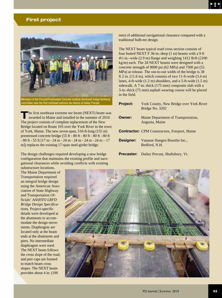
The first northeast extreme tee beam (NEXT) beam was awarded in Maine and installed in the summer of 2010.
The project consists of complete replacement of the New Bridge located on Route 103 over the York River in the town of York, Maine. The new seven-span, 510-ft-long (155 m) prestressed concrete bridge (55 ft - 80 ft - 80 ft - 80 ft - 80 ft - 80 ft - 55 ft [17 m - 24 m - 24 m - 24 m - 24 m - 24 m – 17 m]) replaces the existing 17-span steel-girder bridge.
The design challenges required developing a new bridge configuration that maintains the existing profile and navi-gational clearances while avoiding conflicts with existing substructure locations. The Maine Department of Transportation required an integral bridge design using the American Asso-ciation of State Highway and Transportation Of-ficials’ AASHTO LRFD Bridge Design Specifica-tions. Project-specific details were developed at the abutments to accom-modate the design move-ments. Diaphragms are located only at the beam ends at the abutments and piers. No intermediate diaphragms were used. The NEXT beam follows the cross slope of the road, and pier caps are formed to match beam cross slopes. The NEXT beam provides about 4 in. (100
mm) of additional navigational clearance compared with a traditional bulb-tee design.
The NEXT beam typical road cross section consists of four butted NEXT F 36-in.-deep (1 m) beams with a 9 ft 4½ in.–wide (2.9 m) flange and weighing 1412 lb/ft (2100 kg/m) each. The 28 NEXT beams were designed with a concrete strength of 9000 psi (62 MPa) and 7500 psi (52 MPa) at release. The out-to-out width of the bridge is 38 ft 2 in. (11.6 m), which consists of two 11-ft-wide (3.4 m) lanes, 4-ft-wide (1.2 m) shoulders, and a 5-ft-wide (1.5 m) sidewalk. A 7-in.-thick (175 mm) composite slab with a 3-in.-thick (75 mm) asphalt wearing course will be placed in the field.
Project: York County, New Bridge over York River Bridge No. 3202
Owner: Maine Department of Transportation, Augusta, Maine
Contractor: CPM Constructors, Freeport, Maine
Designer: Vanasse Hangen Brustlin Inc., Bedford, N.H.
Precaster: Dailey Precast, Shaftsbury, Vt.
Members of the Precast/Prestressed Concrete Institute Northeast bridge technical committee view the first northeast extreme tee beams at Dailey Precast.
Summer 2010 | PCI Journal94
The determination of a live-load distribution factor for the trial designs was not straightforward. The AASHTO LRFD specifications have live-load distribution factors for double-tees; however, the factors are based on the use of adjacent double-tees that are connected using transverse post-tensioning, which is essentially a hinged joint. The proposed use of the NEXT beam includes a composite cast-in-place concrete slab. Therefore, the most appropri-ate live-load distribution factor was to treat each stem as a stringer beam.
This corresponds to the AASHTO LRFD specifications’ distribution factor for cross-section type K in Table 4.6.2.2.1-1. This factor is based on a precast concrete stringer supporting a concrete deck. Because the NEXT beam has a concrete deck, it will behave in a similar fashion to a stringer bridge. Designers may choose to treat the beam as a channel beam with a concrete overlay (cross-section type H in AASHTO LRFD specifications Table 4.6.2.2.1-1). It is the opinion of the committee that the minimum stem spacing of 3 ft (0.9 m) is sufficient to warrant the use of the type K distribution factor.
Preliminary beam designs revealed an issue with the initial beam section. The width of the stems limited the amount of prestressing strand that could be placed in the section, which limited the maximum span lengths. The width of the stems was increased from 11 in. to 13 in. (275 mm to 330 mm), which allowed for the addition of one more column of strand. The additional stem width and strand pattern had a favorable impact on the maximum span length of each section. Therefore, the bottom of the stem width was final-ized at 13 in.
The maximum span length for the largest NEXT beam is about 87 ft (26.5 m). This is within the original limit set by the PCI Northeast bridge technical committee. This span limit is based on the narrowest beam width of 8 ft (2.4 m).
Effect of slab overpour thickness
There was discussion about using the top flange as the bottom portion of the deck slab similar to that of a partial-depth precast concrete deck slab. This would reduce the concrete overpour thickness to about 4 in. (100 mm), as opposed to 8 in. (200 mm) in the original concept. To do this, the top flange required a special design because the overhang portion between beams would be discontinuous at midbay.
A welded-tie connection could be employed, though the PCI Northeast bridge technical committee was not aware of any research of designs that could verify this type of de-sign. Even with this concern, committee members were cu-rious about the effect of reducing the thickness of the slab overpour. Trial beam runs were made for this approach.
Speed of construction
The NEXT beam offers significant advantages over typi-cal stringer-beam bridges. The top flange of the beam is designed to support the weight of the cast-in-place concrete deck. There is no installation or stripping of formwork re-quired in the field. No intermediate diaphragms are included in the NEXT beam, which eliminates a time-consuming construction process. Although end diaphragms are pro-posed to support the free edge of the deck at the supports, it is possible to install these diaphragms during a secondary concrete placement in the precast concrete plant. All of these features should lead to a fast construction process.
Trial designs
Trial designs were completed to ensure that the beam met the goals set by the committee. The bridge technical com-mittee of PCI Northeast comprises seven different DOTs, each with different standards for features such as concrete strength, parapet style, and overlays. To make the trial designs useful, the committee selected the following design parameters that were representative of the majority of the states on the committee:
• a two-lane, four-beam bridge
• parapets consisting of concrete curbing that supports a steel-railing system
• an 8-in.-thick (200 mm), reinforced cast-in-place concrete slab
• a 3-in.-thick (75 mm) bituminous concrete wearing surface
• three different designs of concrete strength:
— 8 ksi (55 MPa) at release and 10 ksi (69 MPa) final
— 6 ksi (41 MPa) at release and 8 ksi (55 MPa) final
— 4 ksi at (28 MPa) at release and 6 ksi (41 MPa) final
• debonding up to 25% of strand
• American Association of State Highway and Trans-portation Officials’ AASHTO LRFD Bridge Design Specifications1 designs with full allowable tension stresses
• straight strand only
• no utility loads
• an interior beam design

95PCI Journal | Summer 2010
Figure 7. This design chart shows spans of the northeast extreme tee (NEXT) with concrete design strengths of 8 ksi (55 MPa) at release and 10 ksi (69 MPa) final. Note: f'c = specified compressive strength of concrete; f'c i = specified compressive strength of concrete at release. 1" = 1 in. = 25.4 mm; 1 ft = 0.305 m; 1 psi = 6.895 kPa; 1 ksi = 6.895 MPa.

Summer 2010 | PCI Journal96
Figure 8. This design chart shows spans of the northeast extreme tee (NEXT) with concrete design strengths of 6 ksi (41 MPa) at release and 8 ksi (55 MPa) final. Note: f'c = specified compressive strength of concrete; f'c i = specified compressive strength of concrete at release. 1 ft = 0.305 m; 1 psi = 6.895 kPa; 1 ksi = 6.895 MPa.
97PCI Journal | Summer 2010
It was found that the reduction in overpour thickness had little effect on the maximum span length. There was an increase in dead-load stresses in the beams with thicker overpours, but there was also a reduction in live-load stresses due to the increased composite section properties with the thicker overpour. This option was abandoned be-cause of the issues with the joints between the beams and the limited change in span capacity. In lieu of this, the PCI Northeast bridge technical committee decided to pursue a full-depth top flange.
Once the first trial runs were complete, the PCI Northeast bridge technical committee developed a series of beam tables for use in preliminary designs. The same parameters were used as in the previous trial runs. The final beam design charts are included in Fig. 7 through 9. The charts in-clude the approximate maximum span length of each section and the approximate number of strands for each section.
With these design charts, a designer can determine a pre-liminary beam depth for a particular span length and beam spacing. These design charts are only intended for prelimi-nary designs. Design parameters for a specific bridge will vary for each project. Therefore, the beam chosen would need to be verified with detailed calculations.
Construction sequence with NEXT beams
The following construction sequence is proposed. The sequence is based on the parameters developed by the committee:
1. Construct the foundations and substructures. The bridge seats should be cast to match the cross slope of the final roadway.
2. Erect the NEXT beams. The beams should be installed to the spacing shown on the plans with ½-in.-thick (13 mm) nominal joints between the beams.
3. Form the deck ends and side faces, and place deck reinforcement (precast concrete curbs or parapets set in grout beds can be used in place of side forms).
4. Cast the bridge deck and end diaphragms. It may be possible to pour the end diaphragms in the fabrication shop before shipping.
5. Complete the parapets.
6. Install a wearing surface if required by the owner agency (bituminous overlay with waterproofing mem-brane or concrete overlay).
During construction, equipment is normally prohibited from the tops of the beams before deck placement. It may
be possible to drive small vehicles across the beams after placement. Designers may want to check the top flange for these loads and either allow or prohibit them during construction.
The weight of the screed would not normally be accounted for in the design of the beam flange overhang in the North-east. This is because the weight of the screed is somewhat unknown to the designer. Contractors typically place the screed rails over the fascia beam. Therefore, the overhang design is not normally an issue. If contractors use the overhang, they need to check the overhang and possibly place additional reinforcement in the overhang to support the screed.
Figure 10 depicts a completed NEXT beam bridge con-structed on a precast concrete integral abutment with a precast concrete open rail parapet.
Future work
Full-depth top-flange option
The PCI Northeast bridge technical committee initially started with a beam design based on a full-thickness concrete slab overpour. There was always a desire by the PCI Northeast bridge technical committee to develop a fully precast concrete butted-beam section without an overpour. This design consists of a full-thickness (8 in. [200 mm]) top flange that acts as the structural slab for the bridge. The sections are butted and the longitudinal joint is connected using headed reinforcing bars combined with a grouted shear key. This connection is based on prelimi-nary findings of several ongoing research projects. Once connected, the entire bridge can be covered with a water-proofing membrane and a bituminous concrete overlay or a concrete overlay.
The development of the full-depth deck sections was completed in January 2010. Span charts indicate that the untopped beam will be capable of span lengths that are similar to the topped section. The weights of the full-depth sections are high, but the PCI Northeast bridge techni-cal committee felt that the section would be an attractive option for short-span local bridges and low-volume roads. Details for the full-depth top-flange option are available at the PCI Northeast website.2
Use of lightweight concrete for the full-depth NEXT beam
The shipping and handling weight of the NEXT beam was a concern for the PCI Northeast bridge technical commit-tee. The reason for the large weight is that each piece is es-sentially two stringers tied together. Therefore, it is about twice the weight of a similar stringer beam of the same span length. The committee also developed span charts for

Summer 2010 | PCI Journal98
Figure 9. This design chart shows spans of the northeast extreme tee (NEXT) beam with concrete design strengths of 4 ksi (28 MPa) at release and 6 ksi (41 MPa) final. Note: f'c = specified compressive strength of concrete; f'c i = specified compressive strength of concrete at release LRFD = load- and resistance-factor design; 1" = 1 in. = 25.4 mm; 1 ft = 0.305 m; 1 psi = 6.895 kPa; 1 ksi = 6.895 MPa.

99PCI Journal | Summer 2010
under-bridge utilities. The utilities are often hung from brackets attached to the bridge parapets.
• The NEXT beam was developed for ease of fabrica-tion. It has only straight strands (no draping), which should reduce the cost of forms and simplify fabrica-tion. The elimination of strand draping has an effect on the efficiency of the section, but the production savings will most likely offset the loss of efficiency. If a designer wants to push the limits of a particular sec-tion, there is the potential for designing a beam with a combination of pretensioning and post-tensioning.
• The performance of a full-depth structural slab on top of the beam is similar to the performance of beams with thinner concrete slabs. The cast-in-place concrete deck provides a durable bridge that is easy to build. The NEXT beam will support the fresh-concrete overpour, eliminating time-consuming and costly deck forming in the field. The top flange can be used to support the beam overhangs, which are often the most difficult portion of the bridge deck to form. The result of this approach is that overall construction time for the NEXT beams should be significantly shorter than typical decked stringer bridges, such as spread box beams and bulb-tees.
• The use of the NEXT beam top flange as a deck form will greatly reduce construction time of typical bridg-es. Intermediate diaphragms are not required, which further reduces construction time. End diaphragms are proposed, which can be precast as a secondary con-crete placement in the plant before installation.
lightweight concrete for the full-depth, top-flange option. The lightweight concrete has the potential to significantly reduce shipping and handling weights, which would cor-respond to a reduction in cost and an increase in potential span lengths.
Pilot projects
The development process has been completed and stan-dards have been approved and issued by the PCI Northeast bridge technical committee. They can be found at the Precast/Prestressed Concrete Institute Northeast Covering New England and New York website at www.pcine.org.2 Each state is looking into locations where the new sec-tion can be used, and projects have already been identified for Massachusetts, New York, Vermont, and Maine. The commitment from the states indicates that the NEXT beam will become a useful section for the region. For an update on the NEXT beam’s pilot project and uses, see the sidebar “First Project.”
Summary
• The development of the NEXT beam is an example of an owner-industry committee collaborating to produce a product that is both owner and fabricator friendly. It has the potential to be used for most short- to mod-erate-span bridges in the region, which are currently being constructed with adjacent precast concrete box beams.
• The NEXT beam has the ability to support under -bridge utilities. The current use of adjacent-box-beam systems for short-span bridges cannot accommodate
Figure 10. This illustration depicts a completed northeast extreme tee beam bridge constructed on a precast concrete integral abutment with a precast concrete open-rail parapet.

Summer 2010 | PCI Journal100
Notation
A = beam width
B = beam depth
C = stem base width
f 'c = specified final compressive strength of concrete
f 'c i = specified compressive strength of concrete at release
I = moment of inertia
Sb = section modulus to bottom fiber
St = section modulus to top fiber
Yb = distance from bottom of beam to center of gravity
Yt = distance from top of beam to center of gravity
• Initial pricing from fabricators indicates that a NEXT beam bridge will be significantly less expensive than a precast concrete adjacent box-beam bridge.
Acknowledgments
The NEXT beam was developed for the purpose of promoting a greater degree of uniformity among DOTs, engineers, and industry of the Northeast with respect to planning, designing, fabricating, and constructing high-way bridges with the Federal Highway Administration’s philosophy of accelerated bridge construction. We would like to acknowledge the PCI Northeast Bridge Techni-cal Committee for its dedication and recommendations in developing the new section. PCI Northeast Bridge Technical Committee members are Rita Seraderian of the Precast/Prestressed Concrete Institute Northeast; Michael P. Culmo and Andrew Benkert of CME Associates Inc.; Eric Calderwood of Calderwood Engineering Etc.; Vartan Sahakian of Commonwealth Engineering and Consulting; Joseph Carrara and Ernie Brod of J. P. Carrara and Sons; Eric Schaffrick and Lee Edwards of Dailey Precast; Darren Conboy of Jacobs Edwards Engineering; Michael Kane of Kane Engineering; Ed Barwicki of Lin Associates; Robert Bulger and Nate Benoit of the Maine DOT; Alex Bardow, Maura Sullivan, and Edmund Newton of the Massachusetts Highway Department; Duane Carpenter, Matthew Royce, and Michael Twiss of the New York State DOT; Jason Tremblay and David Scott of the New Hampshire DOT; Mike Savella of the Rhode Island DOT; Chris Fowler of Rotondo Precast; and George W. Colgrove III of Baker Engineering, formerly of the Vermont Agency of Trans-portation.
Also special thanks to Reid Castrodale of Carolina Stalite Co. for his help in developing the lightweight span charts for the NEXT D standards.
References
1. American Association of State Highway and Trans-portation Officials (AASHTO). 2007. AASHTO LRFD Bridge Design Specifications. 4th ed. Washington, DC: AASHTO.
2. Precast/Prestressed Concrete Institute Northeast Cov-ering New England & New York. NEXT F Standards: Northeast Extreme Bridge Tee Form Standards. www.pcine.org/index.cfm/resources/bridge/ Northeast_Extreme_Tee_Beam.

101PCI Journal | Summer 2010
About the authors
Michael P. Culmo, P.E., is the vice president of Transportation and Structures with CME Associates in East Hartford, Conn.
Rita L. Seraderian, P.E., LEED AP, is the executive director of PCI Northeast in Belmont, Mass.
Synopsis
The bridge technical committee of PCI Northeast has recently developed a standard for a new beam called the northeast extreme tee (NEXT) beam. The goals of this new section are to provide a fast construction option for variable-width bridges with spans up to 90 ft (27 m).
The section resembles a standard double-tee except that the stems are wider to handle the moment and shear demand for bridge loads. The top flange of the
beam is thin and is intended to provide formwork for a cast-in-place concrete deck, which is intended to save substantial time during construction. The beam was designed to be easy to fabricate, which will inevitably lead to lower bridge costs. This paper focuses on the committee’s work in developing the beam and sum-marizes the design criteria and how the committee accomplished those goals.
Keywords
Accelerated bridge construction, double-tee, NEXT, northeast extreme tee
Review policy
This paper was reviewed in accordance with the Precast/Prestressed Concrete Institute’s peer-review process.
Reader comments
Please address any reader comments to PCI Journal editor-in-chief Emily Lorenz at [email protected] or Precast/Prestressed Concrete Institute, c/o PCI Journal, 200 W. Adams St., Suite 2100, Chicago, IL 60606. J