beam structural modelling in hydroelastic analysis of ... · beam structural modelling in...
TRANSCRIPT

10
Beam Structural Modelling in Hydroelastic Analysis of Ultra Large Container Ships
Ivo Senjanović, Nikola Vladimir, Neven Hadžić and Marko Tomić University of Zagreb, Faculty of Mechanical Engineering and Naval Architecture
Croatia
1. Introduction
Ultra large container ships are very sensitive to the wave load of quartering seas due to considerably reduced torsional stiffness caused by large deck openings. As a result, their natural frequencies can fall into the range of encounter frequencies in an ordinary sea spectrum. Therefore, the wave induced hydroelastic response of large container ships becomes an important issue in structural design. Mathematical hydroelastic model incorporates structural, hydrostatic and hydrodynamic parts (Senjanović et al. 2007, 2008a, 2009b, 2010b). Beam structural model is preferable in the early design stage and for determining global response, while for more detailed analyses 3D FEM model has to be used. The hydroelastic analysis is performed by the modal superposition method, which requires dry natural vibrations of the structure to be determined. For each mode dynamic coefficients (added mass and damping) and wave load are calculated based on velocity potential. The governing equation of ship motion in rough sea specified for the impulsive (slamming) load as a transient problem is solved in time domain. The motion equation is also given for the case of harmonic wave excitation (springing), which is solved in the frequency domain. In the chapter, methodology of the ship hydroelastic analysis is described, and position and role of the beam structural model is explained. Beam finite element for coupled horizontal and torsional vibrations, that includes warping of ship cross-section, is constructed. Shear influence on both bending and torsion is taken into account. The strip element method is used for determination of normal and shear stress flows, and stiffness moduli, i.e. shear area, torsional modulus, shear inertia modulus (as a novelty), and warping modulus. In the modelling of large container ships it is important to appropriately account for the contribution of transverse bulkheads to hull stiffness and the behavior of relatively short engine room structure. In the former case, the equivalent torsional modulus is determined by increasing ordinary (St. Venant) value, depending on the ratio of the strain energy of a bulkhead and corresponding hull portion. Equivalent torsional modulus of the engine room structure is also determined utilizing the energy approach. It is assumed that a short closed structure behaves as an open one with the contribution of decks. Application of the beam structural model for ship hydroelastic analysis is illustrated in case of a very large container ship. Correlation of dry natural vibrations analysis results for the beam model with those for 3D FEM model shows very good agreement. Hydroelastic analysis emphasizes peak values of transfer functions of displacements and sectional forces
Recent Advances in Vibrations Analysis
194
in resonances, i.e. in the case when the encounter frequency is equal to one of the natural frequencies.
2. Methodology of ship hydroelastic analysis
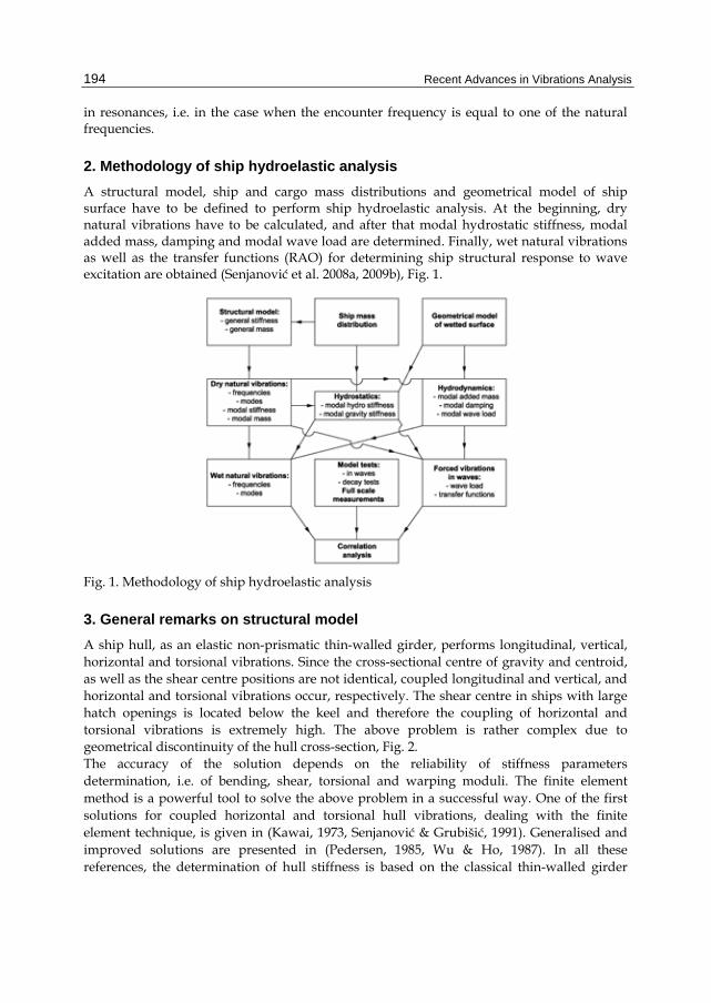
A structural model, ship and cargo mass distributions and geometrical model of ship surface have to be defined to perform ship hydroelastic analysis. At the beginning, dry natural vibrations have to be calculated, and after that modal hydrostatic stiffness, modal added mass, damping and modal wave load are determined. Finally, wet natural vibrations as well as the transfer functions (RAO) for determining ship structural response to wave excitation are obtained (Senjanović et al. 2008a, 2009b), Fig. 1.
Fig. 1. Methodology of ship hydroelastic analysis
3. General remarks on structural model
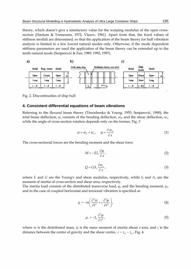
A ship hull, as an elastic non-prismatic thin-walled girder, performs longitudinal, vertical, horizontal and torsional vibrations. Since the cross-sectional centre of gravity and centroid, as well as the shear centre positions are not identical, coupled longitudinal and vertical, and horizontal and torsional vibrations occur, respectively. The shear centre in ships with large hatch openings is located below the keel and therefore the coupling of horizontal and torsional vibrations is extremely high. The above problem is rather complex due to geometrical discontinuity of the hull cross-section, Fig. 2. The accuracy of the solution depends on the reliability of stiffness parameters determination, i.e. of bending, shear, torsional and warping moduli. The finite element method is a powerful tool to solve the above problem in a successful way. One of the first solutions for coupled horizontal and torsional hull vibrations, dealing with the finite element technique, is given in (Kawai, 1973, Senjanović & Grubišić, 1991). Generalised and improved solutions are presented in (Pedersen, 1985, Wu & Ho, 1987). In all these references, the determination of hull stiffness is based on the classical thin-walled girder
Beam Structural Modelling in Hydroelastic Analysis of Ultra Large Container Ships
195
theory, which doesn’t give a satisfactory value for the warping modulus of the open cross-section (Haslum & Tonnessen, 1972, Vlasov, 1961). Apart from that, the fixed values of stiffness moduli are determined, so that the application of the beam theory for hull vibration analysis is limited to a few lowest natural modes only. Otherwise, if the mode dependent stiffness parameters are used the application of the beam theory can be extended up to the tenth natural mode (Senjanović & Fan, 1989, 1992, 1997).
.
Fig. 2. Discontinuities of ship hull
4. Consistent differential equations of beam vibrations
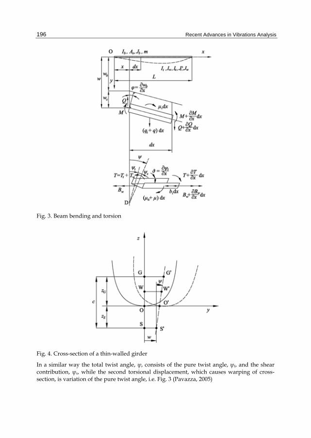
Referring to the flexural beam theory (Timoshenko & Young, 1955, Senjanović, 1990), the total beam deflection, w, consists of the bending deflection, wb, and the shear deflection, ws, while the angle of cross-section rotation depends only on the former, Fig. 3
, bb s
ww w w φ
x (1)
The cross-sectional forces are the bending moment and the shear force
,bM EIx
(2)
,ss
wQ GA
x (3)
where E and G are the Young's and shear modulus, respectively, while Ib and As are the moment of inertia of cross-section and shear area, respectively. The inertia load consists of the distributed transverse load, qi, and the bending moment, μi, and in the case of coupled horizontal and torsional vibration is specified as
2 2
2 2 ,i
wq m c
t t (4)
2
2 ,i bJt
(5)
where m is the distributed mass, Jb is the mass moment of inertia about z-axis, and c is the distance between the centre of gravity and the shear centre, G Sc z z , Fig. 4.
Recent Advances in Vibrations Analysis
196
Fig. 3. Beam bending and torsion
Fig. 4. Cross-section of a thin-walled girder
In a similar way the total twist angle, ψ, consists of the pure twist angle, ψt, and the shear contribution, ψs, while the second torsional displacement, which causes warping of cross-section, is variation of the pure twist angle, i.e. Fig. 3 (Pavazza, 2005)

Beam Structural Modelling in Hydroelastic Analysis of Ultra Large Container Ships
197
, .tt s x
(6)
The cross-sectional forces include the pure torsional torque, Tt, warping bimoment, Bw, and additional torque due to restrained warping, Tw
,t tT GI (7)
,w wB EIx
(8)
,sw sT GI
x (9)
where It, Iw and Is are the torsional modulus, warping modulus and shear inertia modulus, respectively. The inertia load consists of the distributed torque, μti, and the bimoment, bi, presented in the following form:
2 2
2 2 ,ti t
wJ mc
t t (10)
2
2 ,i wb Jt
(11)
where Jt is the mass polar moment of inertia about the shear centre, and Jw is the mass bimoment of inertia with respect to the warping centre, Fig. 4. Considering the equilibrium of a beam differential element, one can write for flexural vibrations
,i
MQ μ
x (12)
,i
Qq q
x
(13)
and for torsional vibrations (Pavazza, 1991)
,ww i
BT b
x
(14)
.t wti
T Tμ μ
x x
(15)
The above equations can be reduced to two coupled partial differential equations as follows. Substituting Eqs. (2) and (3) into (12) yields
Recent Advances in Vibrations Analysis
198
2 2
2 2 .s b b
s s
w EI Jx GA x GA t
(16)
By inserting Eqs. (3) and (4) into (13) leads to
4 2 4 4 3
4 2 2 2 4 2 .b bb b
s s
qEI mJEI m J m mc
x t GA x t GA t x t x
(17)
In a similar way, substituting Eqs. (8) and (9) into (14) yields
2 2
2 2 .s w w
s s
EI Jx GI x GI t
(18)
By inserting Eqs. (7), (9) and (10) into (15) one finds
4 2 2 4 4 3
4 2 2 2 2 4 2 .w ww t t w t
s s
EI J wEI GI J J J mc
x x t GI x t GI t x t x
(19)
Furthermore, ψ in (17) can be split into t s and the later term can be expressed with (18).
Similar substitution can be done for b sw w w in (19), where ws is given with (16). Thus,
taking into account that /bw x and /t x , Eqs. (17) and (19) after integration
per x read
4 2 4 4
4 2 2 2 4
2 4 4
2 2 2 4
b b b b b bb b
s s
t w t w t
s s
w w EI w mJ wEI m J m
x t GA x t GA t
EI Jmc q
t GI x t GI t
(20)
4 2 2 4
4 2 2 2 2
4 2 4 4
4 2 2 2 4 .
t t t w tw t t w t
s
w t b b b b b
s s s
EIEI GI J J J
x x t GI x t
J w EI w J wmc
GI t t GA x t GA t
(21)
After solving Eqs. (20) and (21) the total deflection and twist angle are obtained by employing (16) and (18), i.e.
2 2
2 2b b b b
b s bs s
EI w J ww w w w f t
GA x GA t
(22)
2 2
2 2w t w t
t s ts s
EI Jg t
GI x GI t
(23)
where f(t) and g(t) are integration functions, which depend on initial conditions. The main purpose of developing differential equations of vibrations (20) and (21) is to get insight into their constitution, position and role of the stiffness and mass parameters, and

Beam Structural Modelling in Hydroelastic Analysis of Ultra Large Container Ships
199
coupling, which is realized through the inertia terms. If the pure torque Tt is excluded from the above theoretical consideration, it is obvious that the complete analogy between bending and torsion exists, (Pavazza, 1991). Application of Eqs. (20) and (21) is limited to prismatic girders. For more complex problems, like ship hull, the finite element method is on disposal. The shape functions of beam finite element for vibration analysis have to satisfy the following consistency relations for harmonic vibrations obtained from Eqs. (22) and(23), (Senjanović, 1990)
2
22
d1
db b b
b s bs s
J EI ww w w w
GA GA x
(24)
2
22
d1 .
dw w t
t s ts s
J EIGI GI x
(25)
5. Beam finite element
The properties of a finite element for the coupled horizontal and torsional vibration analysis can be derived from the total element energy. It consists of the strain energy, the kinetic energy, the work of the distributed external lateral load, q, and the torque, μ, and the work of the boundary forces. Thus, according to (Senjanović, 1990, Senjanović & Grubišić, 1991),
2 2 2 222 2
2 20
2 2 2 22 2
0
1d
2
12 d
2
(
lb s t ts
tot b s w s t
lb t
b w t
w wE EI GA EI GI GI x
x x x x x
w w wm J mc J J x
t x t t t x t t
qw
00
)d ( ) ,l
lwx Qw M T B
(26)
where l is the element length. Since the beam has four displacements, , , ,w , a two-node finite element has eight degrees of freedom, i.e. four nodal shear-bending and torsion-warping displacements respectively, Fig. 5,
(0) (0)(0) (0)
,( ) ( )( ) ( )
w
U Vw l l
l l
(27)
Therefore, the basic beam displacements, wb and ψt, can be presented as the third-order polynomials
, , 0,1,2, 3 ,
, . . . . . . .
k kb k t k
T
w a d k
xl
(28)

Recent Advances in Vibrations Analysis
200
Furthermore, satisfying alternately the unit value for one of the nodal displacement {U} and zero values for the remaining displacements, and doing the same for {V}, it follows that:
, , ,
, , , 1,2,3, 4,b bi s si i
t ti s si i
w w U w w U w w U
V V V i
(29)
where wbi, wsi, wi and ψti, ψsi, ψi are the shape functions specified below by employing relations (24) and (25)
, ,
, ,
k k kbi ik si ik i ik
k k kti ik si ik i ik
w a w b w c
d e f
(30)
2
2
6 0 3 24 3 12 2 31
6 0 3 2122 6 0 6
ik
α β α αβ α β l α α β l α α β l α l
aβ α αα α β
β α β l α α β l α l
(31)
Fig. 5. Beam finite elemet

Beam Structural Modelling in Hydroelastic Analysis of Ultra Large Container Ships
201
0 0 2
1 1 3
2 2
3 3
1 2
1 6
1
1 ,
i i i
i i i
i i
i i
b α a βa
b α a βa
b α a
b α a
(32)
ik ik ikc a b i k, 1,2,3,4, 0,1,2,3 (33)
221 , b b
s s
J EIGA GA l
(34)
Constitution of torsional matrices ikd , ike and ikf is the same as ika , ikb and
ikc , but parameters α and β have to be exchanged with
221 , w w
s s
J EIGI GI l
(35)
according to (25). By substituting Eqs. (29) (26) one obtains
01 1
,02 2
TT T T
bs sb sttot
ws t ts tw
U k U U m m U q U P UE
V k k V m m V R VV V
(36)
where, assuming constant values of the element properties, 22
2 20 0
d dddd d
d d d d
l lbj sjsibi
b sbs
w wwwk EI x GA x
x x x x
– bending-shear stiffness matrix,
22
2 20 0
d dddd d
d d d d
l ltj sjsiti
w swsk EI x GI x
x x x x
– warping-shear stiffness matrix,
0
ddd
d d
ltjti
ttk GI x
x x
– torsion stiffness matrix,
0 0
ddd d
d d
l lbjbi
i j bsb
wwm m w w x J x
x x
– shear-bending mass matrix,
0 0
ddd d
d d
l ltjti
t i j wtwm J x J x
x x
– torsion-warping mass matrix,
0
d ,l
T
i jst ts stm mc w x m m
– shear-torsion mass matrix,
0
0
d – shear load vector,
d – torsion load vector,
, 1,2,3, 4.
l
j
l
j
q q w x
x
i j
(37)

Recent Advances in Vibrations Analysis
202
The vectors {P} and {R} in Eq. (36) represent the shear-bending and torsion-warping nodal forces, respectively,
(0) (0)(0) (0)
,( ) ( )( ) ( )
w
w
Q TM B
P RQ l T lM l B l
(38)
The above matrices are specified in Appendix A, as well as the load vectors for linearly distributed loads along the finite element, i.e.
0 1 0 1, .q q q (39)
The total element energy has to be at its minimum. Satisfying the relevant conditions
0 , 0tot totE EU V
(40)
and employing Lagrange equations of motion, the finite element equation yields
,q
f k m f
(41)
where
, ,
0, .
0
q
bs sb st
ws t ts tw
P q Uf f
R V
k m mk m
k k m m
(42)
It is obvious that coupling between the bending and torsion occurs through the mass matrix only, i.e. by the coupling matrices [m]st and [m]ts.
6. Contribution of transverse bulkheads to the hull stiffness
This problem for container ships is extensively analyzed in (Senjanović et al., 2008b), where torsional modulus of ship cross-section is increased proportionally to the ratio of bulkhead strain energy and strain energy of corresponding hull portion. The bulkhead is considered as an orthotropic plate with very strong stool (Szilard, 2004). Bulkhead strain energy is determined for the given warping of cross-section as a boundary condition. The warping causes bulkhead screwing and bending. Here, only the review of the final results is presented. Bulkhead deflection (axial displacement) is given by the following formula, Fig. 6:
2 2
, 1 2 ,y z z
u y z y z db H H
(43)

Beam Structural Modelling in Hydroelastic Analysis of Ultra Large Container Ships
203
where H is the ship height, b is one half of bulkhead breadth, d is the distance of warping centre from double bottom neutral line, y and z are transverse and vertical coordinates, respectively, and is the variation of twist angle.
Fig. 6. Shape of bulkhead deformation
The bulkhead grillage strain energy includes vertical and horizontal bending with contraction and torsion (Senjanović et al., 2008b).
3 3
22
1 116 32 8 1431
1 35 105 75 75g y z y z t
H b Hb HbU i i i i i E
b H
(44)
where iy, iz and it are the average moments of inertia of cross-section and torsional modulus per unit breadth, respectively. The stool strain energy is comprised of the bending, shear and torsional contributions
2 22
23
12 972 1
10 1sb sb st
ss
h I I bIhU E
b b A
(45)
where Isb, As and Ist are the moment of inertia of cross-section, shear area and torsional modulus, respectively. Quantity h is the stool distance from the inner bottom, Fig. 7.
Fig. 7. Longitudinal section of container ship hold

Recent Advances in Vibrations Analysis
204
The equivalent torsional modulus yields, Fig. 7
21 0
4 11 , ,g s
t tt
U UCaI I C
l I l E
(46)
where a is the web height of bulkhead girders (frame spacing), l0 is the bulkhead spacing,
1 0l l a is the net length, and C is the energy coefficient.
7. Contribution of engine room structure to the hull stiffness
Ultra Large Container Ships are characterized by relatively short engine room structure with length of about a half of ship breadth. Its complex deformation is illustrated in a case of a 7800 TEU container ship, Fig. 8. The deck shear deformation is predominant, while hold transverse bulkhead stool is exposed to bending. Due to shortness of the engine room, its transverse bulkheads are skewed but somewhat less pronounced than warping of the hold bulkheads. Warping of the transom is negligible, and that is an important fact when specifying boundary conditions in vibration analysis.
Fig. 8. Deformation of 7800 TEU container ship aft structure
7.1 Stiffness of engine room structure A short engine room structure can be considered either as a closed segment with relevant stiffness or as an open segment with increased stiffness due to deck contribution (Pedersen, 1985). The latter simulation in fact gives results which agree better with 3D FEM results, than the former one (Pedersen, 1983). Deck contribution to hull stiffness can be determined by energy approach, as it is done in the case of transverse bulkheads (Senjanović et al., 2008b). Such a beam model is consistent at global level of energy balance, and that is sufficient for application in ship hydroelastic analysis, where proper natural frequencies and mode shapes of dry hull are required. In the case of short engine room, torsion induces distortion of cross-section while hull bending is negligible. Solution of that complex problem is described here by employing the energy balance approach and concept of the effective stiffness due to reason of simplicity. A

Beam Structural Modelling in Hydroelastic Analysis of Ultra Large Container Ships
205
closed hull segment is considered as open one with deck influence. For that purpose let us determine deck strain energy. All quantities related to closed and open cross-section are designated by .
and . , respectively As it can be seen in Fig. 8, the upper deck is exposed to large deformation, while the double bottom in-plane deformation is quite small. The relative axial displacement of the internal upper deck boundaries, with respect to double bottom, is result of their warping
D B D B tU U U w w (47)
It causes deck in-plane (membrane) deformation. The problem can be solved in an approximate analytical way by considering deck as a beam. Its horizontal anti-symmetric deflection consists of pure bending and shear contribution, Fig. 9. The former is assumed in the form
2
3 ,2b b
y yu U
b b
(48)
which satisfies relevant boundary conditions: 0 0bu and 0 0bu , where bU is the
boundary bending deflection. Shear deflection depends on bending deflection
dd
22
2 2 1 ,bs b
yuEI au U
GA y b b
(49)
where the internal deck cross-section area, 2A at , its moment of inertia, 323
I a t , and the
relation 2 1E ν G , are taken into account, Fig. 9. Total deflection is obtained by
summing up its constitutive parts, Eqs. (48) and (49). Relation between total boundary deflection and the bending boundary deflection reads
2
1 2 1 b
aU U
b
(50)
Fig. 9. Deck deformation and double bottom rotation, a)-bird view, b)-lateral view

Recent Advances in Vibrations Analysis
206
The total internal deck strain energy consists of the bending and shear contributions
d dd dd d
2 22
1 2
1 12 2
b bb s
b b
u uE EI y GA y
y y
(51)
By substituting Eqs. (48) and (49) into (51), one finds
3 2
21 4 1 1 2 1 b
a aE ν Gt ν U
b b
(52)
Finally, by taking into account Eqs. (47) and (50), yields
3
2 21 2
4 1
1 2 1D B t
aν Gt
bE w w ψ
aν
b
(53)
On the other hand, total energy of the closed hull segment can be obtained by summing up energy of open segment and the deck strain energy, i.e.
1tot w t μE E E E E (54)
where
d d d1 1, , .
2 2
a a a
w w t t t t μ xa a a
E B ψ x E T ψ x E μ ψ x
(55)
Within a short span 2a, constant value of tψ (as for deck) can be assumed, so that second
term in Eq. (26) by inserting tT from Eqs. (7), leads to
2 .t t tE GI aψ (56)
tE and 1E in (54) can be unified into one term since both depend on 2
tψ
21t t tE E GaI ψ
(57)
where
11 , t tt
EI C I C
E
(58a, b)
tI is the effective torsional modulus which includes both open cross-section and deck
effects. Engine room structure is designed in such a way that the hold double skin continuity is ensured and necessary decks are inserted between the double skins. Strain energy is derived for the first (main) deck and for the others it can be assumed that their strain energy is

Beam Structural Modelling in Hydroelastic Analysis of Ultra Large Container Ships
207
proportional to the deck plating volume, V, and linearly increasing deformation with the deck distance from inner bottom, h, Fig. 9, since the double bottom is much stiffer than decks. In that way the coefficient C, Eq. (58b), by employing (53) and (56), reads
32
1
2
4 1
1 2 1
D Bi
t
t
aν t w w k
E bCE a
ν I ab
(59)
where
2
1 1
.i iV hk
V h
(60)
In the above consideration distortion of cross-sections is not included and that is subject of further investigation.
7.2 Torsion of segmented girder Let us consider a girder consisted of three segments, Fig. 10. The end segments are open and the middle one is closed, so that the girder is symmetric with respect to the z axis. Each segment is specified in its local coordinate system. The properties of the middle and end segments are designated by .
and . , respectively. The relevant expressions for displacements and sectional forces are listed below (Senjanović et al., 2009a, 2010a):
12 3
12 3
2 3
1
dsh ch ,
d
sh ch ,
sh ch ,
,
tp
t t p
w t w p
t p w p
ψ Au w w A α αx A α αx ψ
x l
AT GI A α αx A α αx ψ
l
T GI A α αx A α αx EI ψ
AT GI ψ EI ψ
l
(61)
2 3ch sh ,w t w pB GI A αx A αx EI ψ
where pψ represents particular solution of differential equation and coefficient α yields
.t
w
GIα
EI (62)
The symbols iA and iB are used for the integration constants of the closed and open segments. The girder is loaded with torque Mt at the ends, while 0xμ . The ends are fixed against warping. The boundary and compatibility conditions in the considered case, yield

Recent Advances in Vibrations Analysis
208
0 , 0 ,
0 , 0 ,
0, .
t t
w w
t
ψ a ψ ψ a ψ
T a T B a B
u l T l M
(63)
Fig. 10. Torsion of segmented girder
From the third and last conditions (63) one finds
1 1, .t t
tt
M a M lA B
GIGI
(64)
The remaining four conditions (63) lead to the system of algebraic equations (Senjanović et al., 2010a) and its analytical solution reads:
3 323 2 3, , , A BBD DD
A B BD D D
(65)
where
3
2
3
1 ch 1 ,
sh 1 ch ,
1 sh sh ch ,
ch ch sh sh .
t tA
t
t t tB
t t
t tB
t
t t
M ID βl
G I
M I ID αa βl
G I I
M I αD αa βl αa
G I β
D I α αa βl I β αa βl
(66)
8. Numerical procedure for vibration analysis
A thin-walled girder is modelled with a set of beam finite elements. Their assemblage in the global coordinate system, performed in the standard way, results in the matrix equation of motion, which may be extended by the damping forces

Beam Structural Modelling in Hydroelastic Analysis of Ultra Large Container Ships
209
Δ Δ Δ ( ) ,K C M F t
(67)
where [K], [C] and [M] are the stiffness, damping and mass matrices, respectively;
Δ , Δ and Δ are the displacement, velocity and acceleration vectors, respectively; and
{F(t)} is the load vector. In case of natural vibration {F(t)} = {0} and the influence of damping is rather low for the most of the structures, so that the damping forces may be ignored. Assuming
Δ e ,iωtφ (68)
where φ and ω are the mode vector and natural frequency respectively, Eq. (67) leads to
the eigenvalue problem
2 0K ω M φ , (69)
which may be solved by employing different numerical methods (Bathe, 1996) The basic one is the determinant search method in which ω is found from the condition
2 0K ω M (70)
by an iteration procedure. Afterwards, φ follows from (69) assuming unit value for one element in φ . The forced vibration analysis may be performed by direct integration of Eq. (67), as well as by the modal superposition method. In the latter case the displacement vector is presented in the form
Δ φ X , (71)
where φ φ is the undamped mode matrix and {X} is the generalised displacement vector. Substituting (71) into (67), the modal equation yields
( )k X c X m X f t , (72)
where
– modal stiffness matrix
– modal damping matrix
– modal mass matrix
( ) ( ) – modal load vector.
T
T
T
T
k φ K φ
c φ C φ
m φ M φ
f t φ F t
(73)
The matrices [k] and [m] are diagonal, while [c] becomes diagonal only in a special case, for instance if [C] = α0 [M] + β0 [K], where α0 and β0 are coefficients (Senjanović, 1990). Solving (72) for undamped natural vibration, [k] = [ω2m] is obtained, and by its backward substitution into (72) the final form of the modal equation yields

Recent Advances in Vibrations Analysis
210
2 2 ( )ω X ω ζ X X φ t , (74)
where
– natural frequency matrix
– relative damping matrix2 ( )
( )( ) – relative load vector.
ii
ii
ij
ii ii
i
ii
kω
m
cζ
k m
f tφ t
m
(75)
If [ζ] is diagonal, the matrix Eq. (74) is split into a set of uncoupled modal equations. If vibration excitation is of periodical nature it can be split into harmonics, and the structure response for each of them is determined in the frequency domain. In a case of general or impulsive excitation the vibration problem has to be solved in the time domain. Several numerical methods are available for this purpose, as for instance the Houbolt, the Newmark and the Wilson θ method (Bathe, 1996), as well as the harmonic acceleration method (Lozina, 1988, Senjanović, 1984). It is important to point out that all stiffness and mass matrices of the beam finite element (and consequently those of the assembly) are frequency dependent quantities, due to coefficients α and η in the formulation of the shape functions, Eqs. (34) and (35). Therefore, for solving the eigenvalue problem (69) an iteration procedure has to be applied. As a result of frequency dependent matrices, the eigenvectors are not orthogonal. If they are used in the modal superposition method for determining forced response, full modal stiffness and mass matrices are generated. Since the inertia terms are much smaller than the deformation ones in Eqs. (24) and (25), the off-diagonal elements in modal stiffness and mass matrices are very small compared to the diagonal elements and can be neglected. It is obvious that the usage of the physically consistent non-orthogonal natural modes in the modal superposition method is not practical, especially not in the case of time integration. Therefore, it is preferable to use mathematical orthogonal modes for that purpose. They are created by the static displacement relations yielding from Eqs. (24) and (25) with 0ω , that leads to 1α η . In that case all finite element matrices, defined with Eqs. (37) and in Appendix A, can be transformed into explicit form, Appendix B.
9. Cross-section properties of thin-walled girder
Geometrical properties of a thin-walled girder include cross-section area A, moment of inertia of cross-section Ib, shear area As, torsional modulus It, warping modulus Iw and shear inertia modulus Is. These parameters are determined analytically for a simple cross-section as pure geometrical properties (Haslum & Tonnessen, 1972, Pavazza, 1991, 2005, Vlasov, 1961). However, determination of cross-section properties for an open multi-cell cross-section, as for instance in case of ship structures, is quite a difficult task. Therefore, the strip element method is applied for solving this statically indetermined problem (Cheung, 1976). That is well-known and widely used theory of thin-walled girders, which is only briefly described

Beam Structural Modelling in Hydroelastic Analysis of Ultra Large Container Ships
211
here. Firstly, axial node displacements are calculated due to bending caused by shear force, and due to torsion caused by variation of twist angle. Then, shear stress in bending τb, shear stress due to pure torsion τt, shear and normal stresses due to restrained warping τw and σw, respectively, are determined. Based on the equivalence of strain energies induced by sectional forces and calculated stresses, it is possible to specify cross-section properties in the same formulation as presented below. Furthermore, those formulae can be expressed by stress flows, i.e. stresses due to unit sectional forces (Senjanović & Fan, 1992, 1993). Shear area:
2
2 2
1, b
s b
b bA A
Q τA g
Qτ dA g dA
. (76)
Torsional modulus:
2
2 2
1, t t
t ttt t
A A
T τI g
Tτ dA g dA
. (77)
Shear inertia modulus:
2
2 2
1, w w
s www w
A A
T τI g
Tτ dA g dA
. (78)
Warping modulus:
2
2
2 2
1, ; w w
w w ww Aw w
A A
B σI f I w dA
Bσ dA f dA
. (79)
The above quantities are not pure geometrical cross-section properties any more, since they also depend on Poisson's ratio as a physical parameter. The mass parameters can be expressed with the given mass distribution per unit length, m, and calculated cross-section parameters, i.e.
0, , b b t p w w
m m mJ I J I J I
A A A . (80)
where p by bzI I I is the polar moment of inertia of cross-section.
10. Illustrative numerical examples
For the illustration of the procedure related to engine room effective stiffness determination, 3D FEM analysis of ship-like pontoon has been undertaken. The 3D FEM model is constituted according to 7800 TEU container ship with main dimensions
x x x x319 42.8 24.6ppL B H m, and detailed desciption given in (Tomašević, 2007). The complete hydroelastic analysis of the same ship has been performed. Stiffness properties of ship hull are calculated by program STIFF, based on the theory of thin-walled girders (STIFF, 1990), Fig. 11.

Recent Advances in Vibrations Analysis
212
Fig. 11. Program STIFF – warping of ship cross-section
Influence of the transverse bulkheads is taken into account by using the equivalent torsional modulus for the open cross-sections instead of the actual values, i.e. * 2.4t tI I . This value is applied for all ship-cross sections as the first approximation.
9.1 Analysis of ship-like segmented pontoon Torsion of the segmented pontoon of the length L = 300 m, with effective parameters is considered. Torsional moment Mt = 40570 kNm is imposed at the pontoon ends. The pontoon is considered free in the space and the problem is solved analytically according to the formulae given in Section 4. The following values of the basic parameters are used:
10.1a m, 19.17b m, 1 0.01645t m, 221Dw m2, 267Bw m2, 14.45tI m4,
1.894k . As a result 22.42C , Eq. (59), and accordingly 338.4tI m4, Eq. (58a), are obtained. Since 0.36t tI I , effect of the short engine room structure on its torsional stiffness is obvious.
Fig. 12. Deformation of segmented pontoon, lateral and bird view

Beam Structural Modelling in Hydroelastic Analysis of Ultra Large Container Ships
213
Fig. 13. Lateral, axial, bird and fish views on deformed engine room superelement
Fig. 14. Twist angles of segmented pontoon

Recent Advances in Vibrations Analysis
214
The 3D FEM model of segmented pontoon is made by commercial software package SESAM and consists of 20 open and 1 closed (engine room) superelement. The pontoon ends are closed with transverse bulkheads. The shell finite elements are used. The pontoons are loaded at their ends with the vertical distributed forces in the opposite directions, generating total torque Mt = 40570 kNm. The midship section is fixed against transverse and vertical displacements, and the pontoon ends are constrained against axial displacements (warping). Lateral and bird view on the deformed segmented pontoon is shown in Fig. 12, where the influence of more rigid engine room structure is evident. Detailed view on this pontoon portion is presented in Fig. 13. It is apparent that segment of very stiff double bottom and sides rotate as a “rigid body”, while decks and transverse bulkheads are exposed to shear deformation. This deformation causes the distortion of the cross-section, Fig. 13. Twist angles of the analytical beam solution and that of 3D FEM analysis for the pontoon bottom are compared in Fig. 14. As it can be noticed, there are some small discrepancies between 1 2 Dψ and 3 ,D bottomψ , which are reduced to a negligible value at the pontoon ends
Fig. 14 also shows twist angle of side structure and the difference 3D,bottom 3D,sideδ ψ ψ
represents distortion angle of cross-section which is highly pronounced. As it is mentioned before, the problem will be further investigated.
9.2 Validation of 1D FEM model The reliability of 1D FEM analysis is verified by 3D FEM analysis of the considered ship. For this purpose, the light weight loading condition of dry ship with displacement Δ=33692 t is taken into account. The equivalent torsional stiffness of the engine room structure, as well as equivalent stiffness of fore and aft peaks is not taken into account in this example for the time being. However, it will be done in the next step of investigation. The lateral and bird view of the first dominantly torsional and second dominantly horizontal mode of the wetted surface, determined by 1D model, is shown in Fig. 15.
Fig. 15. The first and second mode, lateral and bird view, light weight, 1D model
The first and second 3D dry coupled natural modes of the complete ship structure are shown in Fig. 16. They are similar to that of 1D analysis for the wetted surface. Warping of the transverse bulkheads, which increases the hull torsional stiffness, is evident.

Beam Structural Modelling in Hydroelastic Analysis of Ultra Large Container Ships
215
The first four corresponding natural frequencies obtained by 1D and 3D analyses are compared in Table 1.
Mode no.
Vert. Horiz. + tors. Mode no.
1D 3D 1D 3D
1 7.35 7.33 4.17 4.15 1(H0 + T1)
2 15.00 14.95 7.34 7.40 2(H1 + T2)
3 24.04 22.99 12.22 12.09 3(H2 + T3)
4 35.08 34.21 15.02 16.22 4(H3 + T4)
Table 1. Dry natural frequencies, light weight, ωi [rad/s]
Fig. 16. The first and second mode, lateral and bird view, light weight, 3D model
Quite good agreement is achieved. Values of natural frequencies for higher modes are more difficult to correlate, since strong coupling between global hull modes and local substructure modes of 3D analysis occurs.
9.3 Hydroelastic response of large container ship Transfer functions of torsional moment and horizontal bending moment at the midship section, obtained using 1D structural model, are shown in Figs. 17 and 18, respectively. The angle of 180° is related to head sea. They are compared to the rigid body ones determined by program HYDROSTAR. Very good agreement is obtained in the lower frequency domain, where the ship behaves as a rigid body, while large discrepancies occur at the resonances of the elastic modes, as expected.

Recent Advances in Vibrations Analysis
216
Fig. 17. Transfer function of torsional moment, χ=120°, U=25 kn, x=155.75 m from AP
Fig. 18. Transfer function of horizontal bending moment, χ=120°, U=25 kn, x=155.75 m from AP
10. Conclusion
Ultra large container ships are quite elastic and especially sensitive to torsion due to large deck openings. The wave induced response of such ships should be determined by using mathematical hydroelastic models which are consisted of structural, hydrostatic and hydrodynamic parts. In this chapter the methodology of ship hydroelastic analysis is briefly described, and the role of structural model is discussed. After that, full detail description of the sophisticated beam structural model, which takes shear influence on torsion, as well as contribution of transverse bulkheads and engine room structure to the hull stiffness, is given. Numerical procedure for vibration analysis is also described and determination of ship cross-section

Beam Structural Modelling in Hydroelastic Analysis of Ultra Large Container Ships
217
properties is explained. The developed theories are illustrated through the numerical examples which include analysis of torsional response of a ship-like segmented pontoon, free vibration analysis of a large container ship and comparison with the results obtained using 3D FEM model, and complete global hydroelastic analysis of a container ship. It is shown that the used sophisticated beam model of ship hull, based on the advanced thin-walled girder theory with included shear influence on torsion and a proper contribution of transverse bulkheads and engine room structure to its stiffness, is a reasonable choice for determining wave load effects. However, based on the experience, stress concentration in hatch corners calculated directly by the beam model is underestimated. This problem can be overcome by applying substructure approach, i.e. 3D FEM model of substructure with imposed boundary conditions from beam response. In any case, 3D FEM model of complete ship is preferable from the viewpoint of determining stress concentration. Concerning further improvements of the beam model, the distortion induced by torsion is of interest. The illustrative numerical example of the 7800 TEU container ship shows that the developed hydroelasticity theory, utilizing sophisticated 1D FEM structural model and 3D hydrodynamic model, is an efficient tool for application in ship hydroelastic analyses. The obtained results point out that the transfer functions of hull sectional forces in case of resonant vibration (springing) are much higher than in resonant ship motion.
11. Acknowledgment
This investigation is carried out within the EU FP7 Project TULCS (Tools for Ultra Large Container Ships) and the project of Croatian Ministry of Science, Education and Sports Load and Response of Ship Structures.
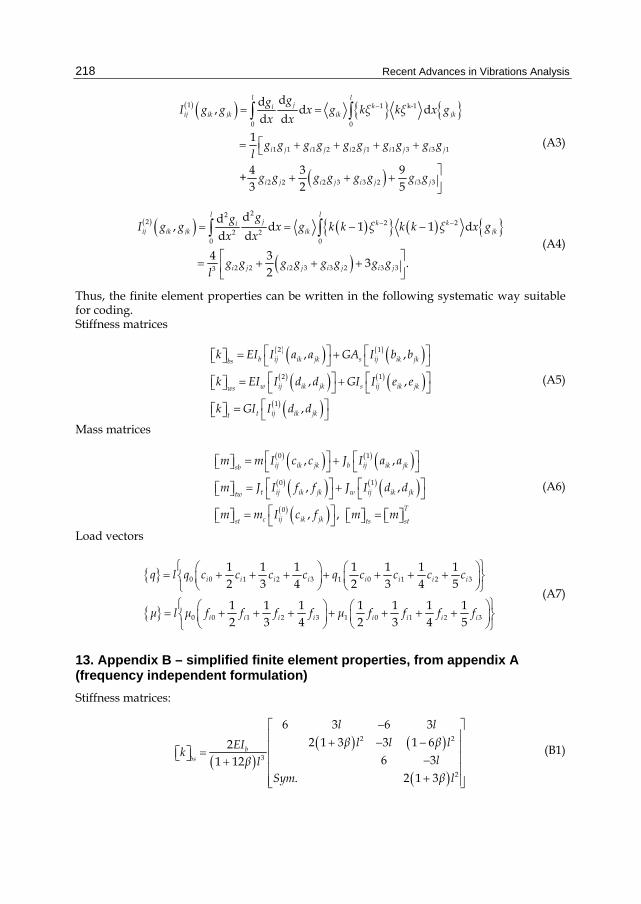
12. Appendix A – consistent finite element properties (frequency dependent formulation)
The stiffness and mass matrices, Eqs. (37), are expressed with one or two integrals, which can be classified in three different types. For general notation of shape functions
, 1,2,3, 4; 0,1,2,3ki ikg g ξ i k , (A1)
where ikq are coefficients and /x l , one finds the solutions of integrals in the following
form:
0
0 0
0 0 1 0 0 1 2 0 1 1 0 2
0 3 1 2 2 1 3 0 1 3 2 2 3 1
, d d
1 1
2 31 1
+4 51
+
l lk k
ij ik jk i j ik jk
i j i j i j i j i j i j
i j i j i j i j i j i j i j
I g g g g x g ξ ξ x g
l g g g g g g g g g g g g
g g g g g g g g g g g g g g
2 3 3 2 3 3
16 7i j i j i jg g g g g g
(A2)
Recent Advances in Vibrations Analysis
218
1 1 k-1
0 0
1 1 1 2 2 1 1 3 3 1
2 2 2 3 3 2 3 3
dd, d d
d d
1
4 3 9 +
3 2 5
l lj ki
ij ik jk ik jk
i j i j i j i j i j
i j i j i j i j
ggI g g x g kξ kξ x g
x x
g g g g g g g g g gl
g g g g g g g g
(A3)
222 2 2
2 20 0
2 2 2 3 3 2 3 33
dd, d 1 1 d
d d
4 3 3 .
2
l lj k ki
ij ik jk ik jk
i j i j i j i j
ggI g g x g k k ξ k k ξ x g
x x
g g g g g g g gl
(A4)
Thus, the finite element properties can be written in the following systematic way suitable for coding. Stiffness matrices
2 1
2 1
1
, ,
, ,
,
b ij ik jk s ij ik jkbs
w ij ik jk s ij ik jkws
t ij ik jkt
k EI I a a GA I b b
k EI I d d GI I e e
k GI I d d
(A5)
Mass matrices
0 1
0 1
0
, ,
, ,
, ,
ij ik jk b ij ik jksb
t ij ik jk w ij ik jktw
T
c ij ik jkst ts st
m m I c c J I a a
m J I f f J I d d
m m I c f m m
(A6)
Load vectors
0 0 1 2 3 1 0 1 2 3
0 0 1 2 3 1 0 1 2 3
1 1 1 1 1 1 12 3 4 2 3 4 5
1 1 1 1 1 1 12 3 4 2 3 4 5
i i i i i i i i
i i i i i i i i
q l q c c c c q c c c c
μ l μ f f f f μ f f f f
(A7)
13. Appendix B – simplified finite element properties, from appendix A (frequency independent formulation)
Stiffness matrices:
2 2
3
2
6 3 6 32 1 3 3 1 62
6 31 12. 2 1 3
bbs
l lβ l l β lEI
klβ l
Sym β l
(B1)

Beam Structural Modelling in Hydroelastic Analysis of Ultra Large Container Ships
219
2 2
3
2
6 3 6 32 1 3 3 1 62
6 31 12. 2 1 3
wws
l lγ l l γ lEI
klγ l
Sym γ l
(B2)
2 2 2 2
2
2 2
36 3 1 60 36 3 1 60
4 1 15 360 3 1 60 1 60 720
36 3 1 6030 1 12
. 4 1 15 360
tt
γ l γ l
γ γ l γ l γ γ lGIk
γ lγ l
Sym γ γ l
(B3)
Mass matrices:
sb s b
m m m (B4)
2 2 2 2
2 2 2 2 2
2 2 2
2 2
156 3528 20160 22 462 2520 54 1512 10080 13 378 2520
4 84 504 13 378 2520 3 84 504
156 3528 20160 22 462 2520420 1 12
. 4 84 504
s
β β β β l β β β β l
β β l β β l β β lmlm
β β β β lβ
Sym β β l
(B5)
2 2 2 2
2
2 2
36 3 180 36 3 180
4 60 1440 3 180 1 60 720
36 3 18030 1 12
. 4 60 1440
b
b
β l β l
β β l β l β β lJm
β lβ l
Sym β β l
(B6)
tw t w
m m m (B7)
2 2 2 2
2 2 2 2 2
2 2 2
2 2
156 3528 20160 22 462 2520 54 1512 10080 13 378 2520
4 84 504 13 378 2520 3 84 504
156 3528 20160 22 462 2520420 1 12
. 4 84 504
t
t
γ γ γ γ l γ γ γ γ l
γ γ l γ γ l γ γ lJ lm
γ γ γ γ lγ
Sym γ γ l
(B8)
2 2 2 2
2
2 2
36 3 180 36 3 180
4 60 1440 3 180 1 60 720
36 3 18030 1 12
. 4 60 1440
w
w
γ l γ l
γ γ l γ l γ γ lJm
γ lγ l
Sym γ γ l
(B9)

Recent Advances in Vibrations Analysis
220
2 2
420 1 12 1 12
156 1764 1764 20160 22 252 210 2520 54 756 756 10080 13 168 210 2520
22 210 252 2520 4 42 42 504 13 210 168 2520 3 42 42 504
54 7
st
mlcm
β γ
β γ βγ β γ βγ l β γ βγ β γ βγ l
β γ βγ l β γ βγ l β γ βγ l β γ βγ l
2 2
56 756 10080 13 168 210 2520 156 1764 1764 20160 22 252 210 2520
13 210 168 2520 3 42 42 504 22 210 252 2520 4 42 42 504
β γ βγ β γ βγ l β γ βγ β γ βγ l
β γ βγ l β γ βγ l β γ βγ l β γ βγ l
(B10)
T
ts stm m (B11)
Load vectors:
0 1
9 12062 30
21 240612 60 1 123 30
ββ llq l q l
qβββ ll
(B12)
0 1
9 12062 30
21 240612 60 1 123 30
γγ llμ l μ l
μγγγ ll
(B13)
Stiffness ratios:
2 2, .b w
s s
EI EIβ γ
GA l GI l (B14)
14. References
Bathe, KJ. (1996). Finite Element Procedures, Prentice Hall Cheung, YK. (1976). Finite Strip Method in Structural Analysis, Pergamon Press Haslum, K. & Tonnessen, A. (1972). An Analysis of Torsion in Ship Hull, European
Shipbuilding, No.5/6, pp. 67-89 Kawai, T. (1973). The Application of Finite Element Method to Ship Structures, Computers &
Structures, Vol.3, No.5, pp. 1175-1194, ISSN 0045-7949 Lozina, Ž. (1988). A Comparison of Harmonic Acceleration Method with the Other
Commonly Used Methods for Calculation of Dynamic Transient Response, Computers & Structures, Vol.29, No.2, pp. 227-240, ISSN 0045-7949
Pavazza, R. (1991). Bending and Torsion of Thin-Walled Beams of Open Section on Elastic Foundation, Ph.D. Thesis. University of Zagreb, (in Croatian)
Pavazza, R. (2005). Torsion of Thin-Walled Beams of Open Cross-Sections with Influence of Shear, International Journal of Mechanical Sciences, Vol.47, No.7, pp. 1099-1122, ISSN 0020-7403
Pedersen, PT. (1983). A Beam Model for the Torsional-Bending Response of Ships Hulls, RINA Transactions, Vol.31, pp. 171-182

Beam Structural Modelling in Hydroelastic Analysis of Ultra Large Container Ships
221
Pedersen, PT. (1985). Torsional Response of Container Ships, Journal of Ship Research, Vol.29, pp. 194-205, ISSN 1542-0604
Senjanović, I. (1984). Harmonic Acceleration Method for Dynamic Structural Analysis, Computers & Structures, Vol.18, No.1, pp. 71-80, ISSN 0045-7949
Senjanović, I. (1990). Ship Vibrations, Part II, University of Zagreb, (in Croatian) Senjanović, I. & Fan, Y. (1989). A Higher-Order Flexural Beam Theory, Computers &
Structures, Vol.32, No.5, pp. 973-986, ISSN 0045-7949 Senjanović, I. & Fan, Y. (1992). A Higher-Order Theory of Thin-Walled Girders with
Application to Ship Structures, Computers & Structures, Vol.43, No.1, pp. 31-52, ISSN 0045-7949
Senjanović, I. & Fan, Y. (1993). A Finite Element Formulation of Initial Ship Cross-Section Properties, Brodogradnja, Vol.41, No.1, pp. 27-36, ISSN 0007-215X
Senjanović, I. & Fan, Y. (1997). A Higher-Order Torsional Beam Theory, International Journal for Engineering Modelling, Vol.32, No.1-4, pp. 25-40, ISSN 1330-1365
Senjanović, I. & Grubišić, R. (1991). Coupled Horizontal and Torsional Vibration of a Ship Hull with Large Hatch Openings, Computers & Structures, Vol.41, No.2, pp. 213-226, ISSN 0045-7949
Senjanović, I., Malenica, Š., Tomašević, S. & Rudan, S. (2007). Methodology of Ship Hydroelastic Investigation, Brodogradnja, Vol.58, No.2, pp. 133-145, ISSN 0007-215X
Senjanović, I. , Tomašević, S., Tomić, M., Rudan, S., Vladimir N. & Malenica, Š. (2008a). Hydroelasticity of Very Large Container Ships, Proceedings of International Conference on Design and Operation of Container Ships, pp. 51-70, RINA, London
Senjanović, I., Tomašević, S., Rudan, S. & Senjanović, T. (2008b). Role of Transverse Bulkheads in Hull Stiffness of Large Container Ships, Engineering Structures, Vol.30, No.9, pp. 2492-2509, ISSN 0141-0296
Senjanović, I., Tomašević, S. & Vladimir, N. (2009a). An Advanced Theory of Thin-Walled Girders with Application to Ship Vibrations, Marine Structures, Vol.22, No.3, pp. 387-437, ISSN 0951-8339
Senjanović, I. , Tomašević, S., Vladimir N. & Malenica, Š. (2009b). Numerical Procedure for Ship Hydroelastic Analysis, Proceedings of International Conference on Computational Methods in Marine Engineering, pp. 259-264, CIMNE, Barcelona
Senjanović, I., Vladimir, N. & Tomić, M. (2010a). The Contribution of the Engine Room Structure to the Hull Stiffness of Large Container Ships, International Shipbuilding Progress, Vol.57, No.1-2, pp. 65-85, ISSN 0020-868X
Senjanović, I. , Tomašević, S., Vladimir N. Tomić, M. & Malenica, Š. (2010b). Application of an Advanced Beam Theory to Ship Hydroelastic Analysis, Proceedings of International Workshop on Advanced Ship Design for Pollution Prevention, pp. 31-42, Taylor & Francis, London
STIFF (1990). User's Manual, University of Zagreb Szilard, R. (2004). Theories and Applications of Plate Analysis, John Wiley & Sons, New York Timoshenko, S. & Young, DH. (1955). Vibrations Problems in Engineering, D. Van Nostrand Tomašević, S. (2007). Hydroelastic Model of Dynamic Response of Container Ship in Waves, Ph.D.
Thesis. University of Zagreb, (in Croatian)

Recent Advances in Vibrations Analysis
222
Vlasov, VZ. (1961). Thin-Walled Elastic Beams, Israel Program for Scientific Translation, Jerusalem
Wu, YS. & Ho, CS. (1987). Analysis of Wave Induced Horizontal and Torsion Coupled Vibrations of Ship Hull. Journal of Ship Research, Vol.31, No.4, pp. 235-252, ISSN 1542-0604