behaviour of expanded metal sheets under shear loading
TRANSCRIPT
7/21/2019 Behaviour of Expanded Metal Sheets Under Shear Loading
http://slidepdf.com/reader/full/behaviour-of-expanded-metal-sheets-under-shear-loading 1/9
ABSTRACTTheoretical study of expanded metal shear panel (EMSP)
has shown that EMSP is to be useful in the seismic retrofittingof buildings. Although this product has merit of strength andductility, it is only used for filters in electrical applications orfor the protection of machines (worker’s safety) or buildings(anti-intrusion) and it is seldom used for structural applications.There is no guidance existing to help the engineers determine
the mechanical properties or to indicate in which field of thestructures this product can be used. With the aims at providing
some quantitative data and insight for these purposes, this paper describes and compares the results of 16 static and staticcyclic experiments of 4 types of expanded metal material insmall-scale. These experiments provide useful information.
The behaviour of expanded metal sheets (EMSs) is very ductileunder monotonic shear loading and stable under quasi-static-cyclic shear loading.Keyword: Expanded Metal, Cyclic behaviour, Cyclic Tests,Hysterical Loops.
I. INTRODUCTION
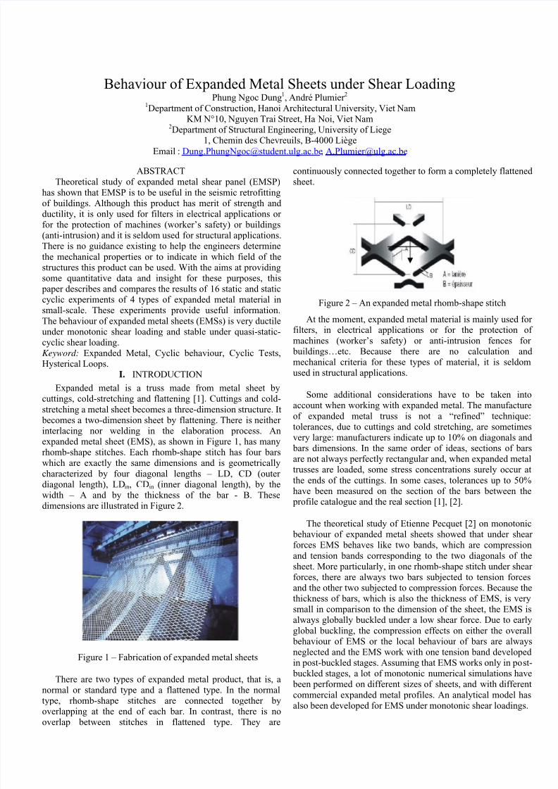
Expanded metal is a truss made from metal sheet bycuttings, cold-stretching and flattening [1]. Cuttings and cold-
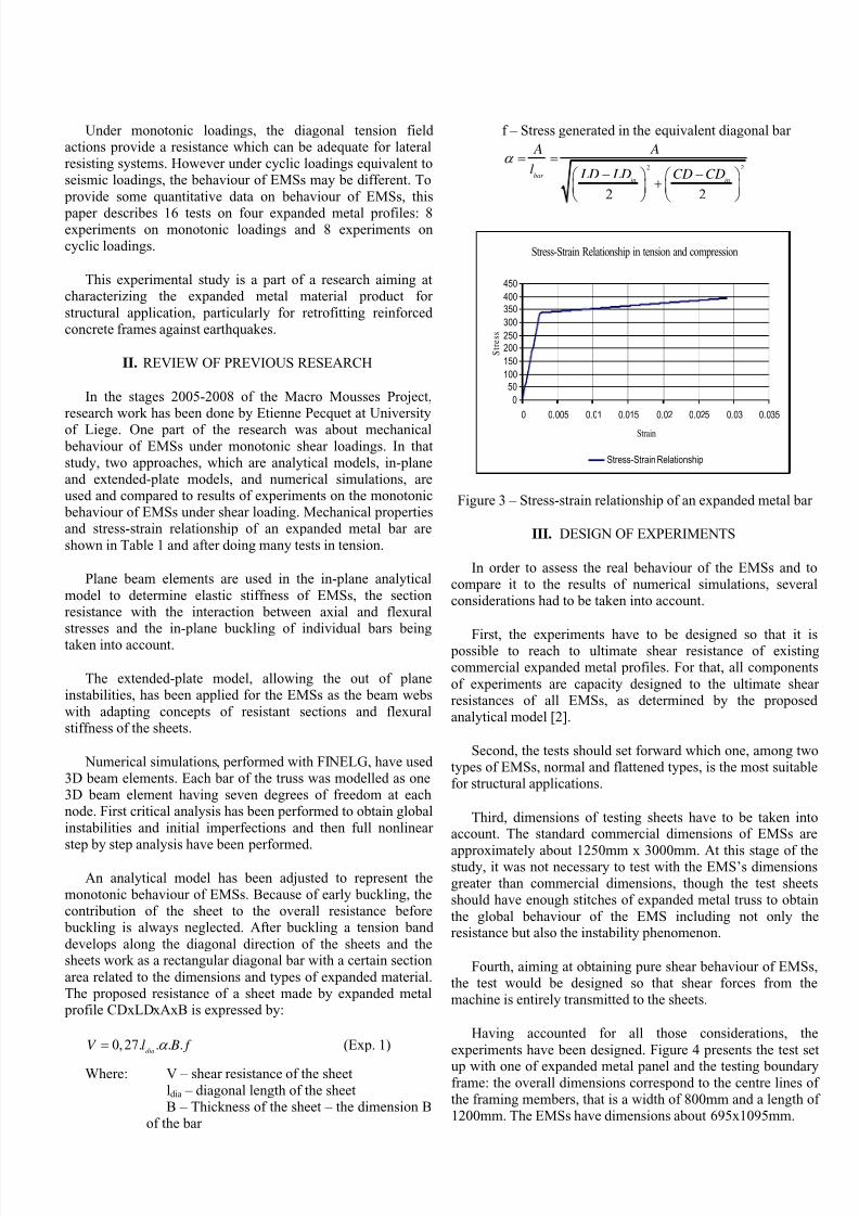
stretching a metal sheet becomes a three-dimension structure. It becomes a two-dimension sheet by flattening. There is neitherinterlacing nor welding in the elaboration process. Anexpanded metal sheet (EMS), as shown in Figure 1, has manyrhomb-shape stitches. Each rhomb-shape stitch has four barswhich are exactly the same dimensions and is geometrically
characterized by four diagonal lengths – LD, CD (outerdiagonal length), LDin, CDin (inner diagonal length), by thewidth – A and by the thickness of the bar - B. Thesedimensions are illustrated in Figure 2.
Figure 1 – Fabrication of expanded metal sheets
There are two types of expanded metal product, that is, a
normal or standard type and a flattened type. In the normaltype, rhomb-shape stitches are connected together byoverlapping at the end of each bar. In contrast, there is nooverlap between stitches in flattened type. They are
continuously connected together to form a completely flattenedsheet.
Figure 2 – An expanded metal rhomb-shape stitch
At the moment, expanded metal material is mainly used forfilters, in electrical applications or for the protection of
machines (worker’s safety) or anti-intrusion fences for buildings…etc. Because there are no calculation andmechanical criteria for these types of material, it is seldomused in structural applications.
Some additional considerations have to be taken intoaccount when working with expanded metal. The manufacture
of expanded metal truss is not a “refined” technique:tolerances, due to cuttings and cold stretching, are sometimesvery large: manufacturers indicate up to 10% on diagonals and bars dimensions. In the same order of ideas, sections of barsare not always perfectly rectangular and, when expanded metaltrusses are loaded, some stress concentrations surely occur at
the ends of the cuttings. In some cases, tolerances up to 50%have been measured on the section of the bars between the profile catalogue and the real section [1], [2].
The theoretical study of Etienne Pecquet [2] on monotonic behaviour of expanded metal sheets showed that under shearforces EMS behaves like two bands, which are compression
and tension bands corresponding to the two diagonals of thesheet. More particularly, in one rhomb-shape stitch under shearforces, there are always two bars subjected to tension forcesand the other two subjected to compression forces. Because thethickness of bars, which is also the thickness of EMS, is verysmall in comparison to the dimension of the sheet, the EMS isalways globally buckled under a low shear force. Due to early
global buckling, the compression effects on either the overall behaviour of EMS or the local behaviour of bars are alwaysneglected and the EMS work with one tension band developedin post-buckled stages. Assuming that EMS works only in post- buckled stages, a lot of monotonic numerical simulations have been performed on different sizes of sheets, and with different
commercial expanded metal profiles. An analytical model hasalso been developed for EMS under monotonic shear loadings.
Behaviour of Expanded Metal Sheets under Shear LoadingPhung Ngoc Dung1, André Plumier 2
1Department of Construction, Hanoi Architectural University, Viet Nam
KM N°10, Nguyen Trai Street, Ha Noi, Viet Nam2Department of Structural Engineering, University of Liege
1, Chemin des Chevreuils, B-4000 LiègeEmail : [email protected], [email protected]
7/21/2019 Behaviour of Expanded Metal Sheets Under Shear Loading
http://slidepdf.com/reader/full/behaviour-of-expanded-metal-sheets-under-shear-loading 2/9
Under monotonic loadings, the diagonal tension fieldactions provide a resistance which can be adequate for lateralresisting systems. However under cyclic loadings equivalent toseismic loadings, the behaviour of EMSs may be different. To
provide some quantitative data on behaviour of EMSs, this
paper describes 16 tests on four expanded metal profiles: 8experiments on monotonic loadings and 8 experiments oncyclic loadings.
This experimental study is a part of a research aiming atcharacterizing the expanded metal material product for
structural application, particularly for retrofitting reinforcedconcrete frames against earthquakes.
II. REVIEW OF PREVIOUS RESEARCH
In the stages 2005-2008 of the Macro Mousses Project,research work has been done by Etienne Pecquet at University
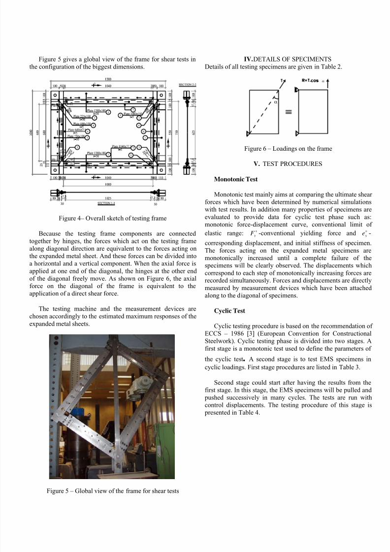
of Liege. One part of the research was about mechanical behaviour of EMSs under monotonic shear loadings. In thatstudy, two approaches, which are analytical models, in-planeand extended-plate models, and numerical simulations, areused and compared to results of experiments on the monotonic behaviour of EMSs under shear loading. Mechanical propertiesand stress-strain relationship of an expanded metal bar are
shown in Table 1 and after doing many tests in tension.
Plane beam elements are used in the in-plane analytical
model to determine elastic stiffness of EMSs, the sectionresistance with the interaction between axial and flexuralstresses and the in-plane buckling of individual bars beingtaken into account.
The extended-plate model, allowing the out of planeinstabilities, has been applied for the EMSs as the beam webs
with adapting concepts of resistant sections and flexuralstiffness of the sheets.
Numerical simulations, performed with FINELG, have used3D beam elements. Each bar of the truss was modelled as one3D beam element having seven degrees of freedom at eachnode. First critical analysis has been performed to obtain global
instabilities and initial imperfections and then full nonlinearstep by step analysis have been performed.
An analytical model has been adjusted to represent themonotonic behaviour of EMSs. Because of early buckling, thecontribution of the sheet to the overall resistance before buckling is always neglected. After buckling a tension band
develops along the diagonal direction of the sheets and thesheets work as a rectangular diagonal bar with a certain section
area related to the dimensions and types of expanded material.The proposed resistance of a sheet made by expanded metal profile CDxLDxAxB is expressed by:
0,27. . . .dia
V l B f α = (Exp. 1)
Where: V – shear resistance of the sheet
ldia – diagonal length of the sheetB – Thickness of the sheet – the dimension B
of the bar
f – Stress generated in the equivalent diagonal bar
2 2
2 2
bar in in
A A
l LD LD CD CDα = =
− −⎛ ⎞ ⎛ ⎞+⎜ ⎟ ⎜ ⎟
⎝ ⎠ ⎝ ⎠
Stress-Strain Relationship in tension and compression
0
50
100
150
200
250
300
350
400
450
0 0.005 0.01 0.015 0.02 0.025 0.03 0.035
Strain
S
t r e s s
Stress-Strain Relationship
Figure 3 – Stress-strain relationship of an expanded metal bar
III. DESIGN OF EXPERIMENTS
In order to assess the real behaviour of the EMSs and tocompare it to the results of numerical simulations, severalconsiderations had to be taken into account.
First, the experiments have to be designed so that it is possible to reach to ultimate shear resistance of existingcommercial expanded metal profiles. For that, all components
of experiments are capacity designed to the ultimate shearresistances of all EMSs, as determined by the proposedanalytical model [2].
Second, the tests should set forward which one, among twotypes of EMSs, normal and flattened types, is the most suitablefor structural applications.
Third, dimensions of testing sheets have to be taken intoaccount. The standard commercial dimensions of EMSs are
approximately about 1250mm x 3000mm. At this stage of thestudy, it was not necessary to test with the EMS’s dimensionsgreater than commercial dimensions, though the test sheetsshould have enough stitches of expanded metal truss to obtain
the global behaviour of the EMS including not only theresistance but also the instability phenomenon.
Fourth, aiming at obtaining pure shear behaviour of EMSs,the test would be designed so that shear forces from themachine is entirely transmitted to the sheets.
Having accounted for all those considerations, the
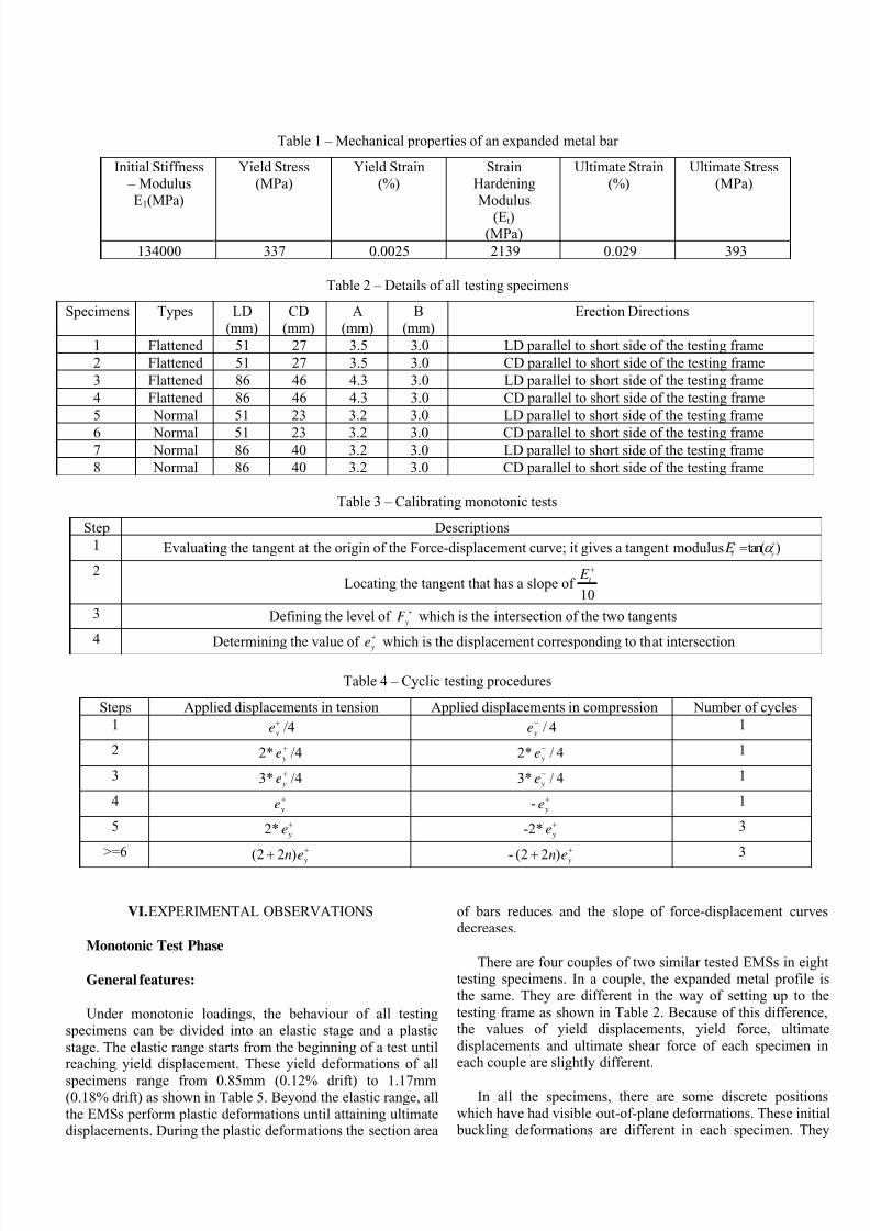
experiments have been designed. Figure 4 presents the test set
up with one of expanded metal panel and the testing boundaryframe: the overall dimensions correspond to the centre lines ofthe framing members, that is a width of 800mm and a length of1200mm. The EMSs have dimensions about 695x1095mm.
7/21/2019 Behaviour of Expanded Metal Sheets Under Shear Loading
http://slidepdf.com/reader/full/behaviour-of-expanded-metal-sheets-under-shear-loading 3/9
Figure 5 gives a global view of the frame for shear tests inthe configuration of the biggest dimensions.
Figure 4– Overall sketch of testing frame
Because the testing frame components are connectedtogether by hinges, the forces which act on the testing framealong diagonal direction are equivalent to the forces acting onthe expanded metal sheet. And these forces can be divided intoa horizontal and a vertical component. When the axial force is
applied at one end of the diagonal, the hinges at the other endof the diagonal freely move. As shown on Figure 6, the axialforce on the diagonal of the frame is equivalent to theapplication of a direct shear force.
The testing machine and the measurement devices arechosen accordingly to the estimated maximum responses of the
expanded metal sheets.
Figure 5 – Global view of the frame for shear tests
IV. DETAILS OF SPECIMENTSDetails of all testing specimens are given in Table 2.
α
α
Figure 6 – Loadings on the frame
V. TEST PROCEDURES
Monotonic Test
Monotonic test mainly aims at comparing the ultimate shearforces which have been determined by numerical simulationswith test results. In addition many properties of specimens are
evaluated to provide data for cyclic test phase such as:monotonic force-displacement curve, conventional limit of
elastic range: yF + -conventional yielding force and ye
+ -
corresponding displacement, and initial stiffness of specimen.The forces acting on the expanded metal specimens aremonotonically increased until a complete failure of thespecimens will be clearly observed. The displacements which
correspond to each step of monotonically increasing forces arerecorded simultaneously. Forces and displacements are directly
measured by measurement devices which have been attachedalong to the diagonal of specimens.
Cyclic Test
Cyclic testing procedure is based on the recommendation ofECCS – 1986 [3] (European Convention for ConstructionalSteelwork). Cyclic testing phase is divided into two stages. A
first stage is a monotonic test used to define the parameters of
the cyclic test. A second stage is to test EMS specimens in
cyclic loadings. First stage procedures are listed in Table 3.
Second stage could start after having the results from thefirst stage. In this stage, the EMS specimens will be pulled and pushed successively in many cycles. The tests are run withcontrol displacements. The testing procedure of this stage is presented in Table 4.
7/21/2019 Behaviour of Expanded Metal Sheets Under Shear Loading
http://slidepdf.com/reader/full/behaviour-of-expanded-metal-sheets-under-shear-loading 4/9
Table 1 – Mechanical properties of an expanded metal bar
Initial Stiffness – Modulus
E1(MPa)
Yield Stress(MPa)
Yield Strain(%)
StrainHardeningModulus
(Et)(MPa)
Ultimate Strain(%)
Ultimate Stress(MPa)
134000 337 0.0025 2139 0.029 393
Table 2 – Details of all testing specimens
Specimens Types LD(mm)
CD(mm)
A(mm)
B(mm)
Erection Directions
1 Flattened 51 27 3.5 3.0 LD parallel to short side of the testing frame
2 Flattened 51 27 3.5 3.0 CD parallel to short side of the testing frame
3 Flattened 86 46 4.3 3.0 LD parallel to short side of the testing frame
4 Flattened 86 46 4.3 3.0 CD parallel to short side of the testing frame
5 Normal 51 23 3.2 3.0 LD parallel to short side of the testing frame
6 Normal 51 23 3.2 3.0 CD parallel to short side of the testing frame7 Normal 86 40 3.2 3.0 LD parallel to short side of the testing frame
8 Normal 86 40 3.2 3.0 CD parallel to short side of the testing frame
Table 3 – Calibrating monotonic tests
Step Descriptions
1 Evaluating the tangent at the origin of the Force-displacement curve; it gives a tangent modulus tan( )t y
E α + +=
2Locating the tangent that has a slope of
10
t E +
3 Defining the level of y
F +
which is the intersection of the two tangents
4Determining the value of ye
+
which is the displacement corresponding to that intersection
Table 4 – Cyclic testing procedures
Steps Applied displacements in tension Applied displacements in compression Number of cycles
1 ye+ /4 / 4 ye
− 1
2 2* ye+
/4 2* / 4 ye−
1
3 3* ye+ /4 3* / 4 ye
− 1
4 ye+ -
ye+ 1
5 2* ye+
-2* ye+
3
>=6 (2 2 ) y
n e++ - (2 2 )
y
n e++ 3
VI. EXPERIMENTAL OBSERVATIONS
Monotonic Test Phase
General features:
Under monotonic loadings, the behaviour of all testingspecimens can be divided into an elastic stage and a plastic
stage. The elastic range starts from the beginning of a test untilreaching yield displacement. These yield deformations of all
specimens range from 0.85mm (0.12% drift) to 1.17mm(0.18% drift) as shown in Table 5. Beyond the elastic range, allthe EMSs perform plastic deformations until attaining ultimatedisplacements. During the plastic deformations the section area
of bars reduces and the slope of force-displacement curvesdecreases.
There are four couples of two similar tested EMSs in eighttesting specimens. In a couple, the expanded metal profile isthe same. They are different in the way of setting up to the
testing frame as shown in Table 2. Because of this difference,the values of yield displacements, yield force, ultimate
displacements and ultimate shear force of each specimen ineach couple are slightly different.
In all the specimens, there are some discrete positionswhich have had visible out-of-plane deformations. These initial
buckling deformations are different in each specimen. They
7/21/2019 Behaviour of Expanded Metal Sheets Under Shear Loading
http://slidepdf.com/reader/full/behaviour-of-expanded-metal-sheets-under-shear-loading 5/9
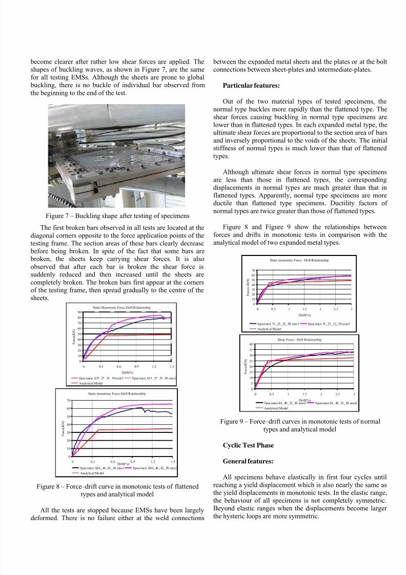
become clearer after rather low shear forces are applied. Theshapes of buckling waves, as shown in Figure 7, are the samefor all testing EMSs. Although the sheets are prone to global buckling, there is no buckle of individual bar observed from
the beginning to the end of the test.
Figure 7 – Buckling shape after testing of specimens
The first broken bars observed in all tests are located at the
diagonal corners opposite to the force application points of thetesting frame. The section areas of these bars clearly decrease before being broken. In spite of the fact that some bars are broken, the sheets keep carrying shear forces. It is also
observed that after each bar is broken the shear force issuddenly reduced and then increased until the sheets are
completely broken. The broken bars first appear at the cornersof the testing frame, then spread gradually to the centre of thesheets.
Static Monotonic Force-Drift Relationship
0
10
20
30
40
50
60
70
80
90
0 0.3 0.6 0.9 1.2 1.5
Drift(%)
F o r c e ( K N )
Specimen A51_27_35_30 sens1 Specimen A51_27_35_30 sens2
Analytical Model
Static monotonic Force-Drift Relationship
0
10
20
30
40
50
60
70
0 0.3 0.6 0.9 1.2 1.5Drift(%)
F o r c e ( K N )
Specimen A86_46_43_30 sens1 Specimen A86_46_43_30 sens2
Analytical Model
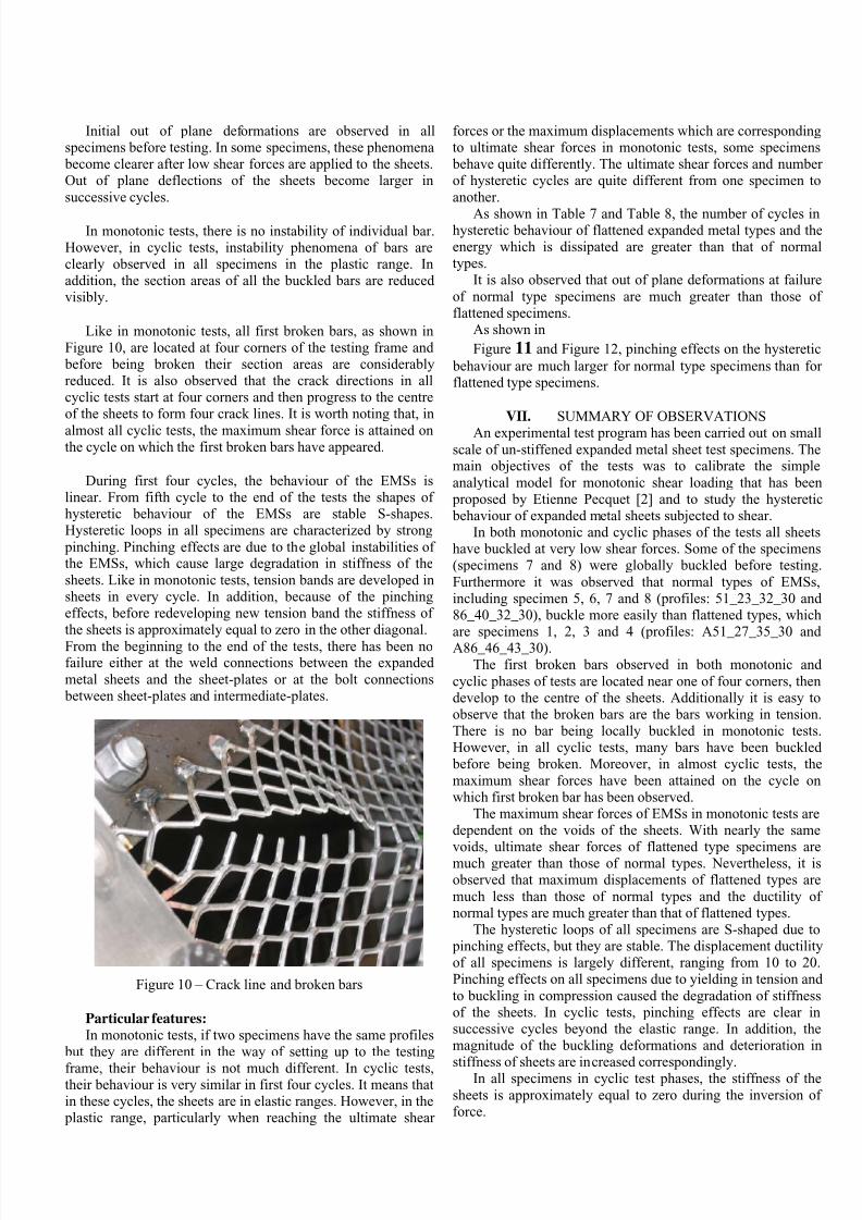
Figure 8 – Force–drift curve in monotonic tests of flattenedtypes and analytical model
All the tests are stopped because EMSs have been largelydeformed. There is no failure either at the weld connections
between the expanded metal sheets and the plates or at the boltconnections between sheet-plates and intermediate-plates.
Particular features:
Out of the two material types of tested specimens, thenormal type buckles more rapidly than the flattened type. Theshear forces causing buckling in normal type specimens arelower than in flattened types. In each expanded metal type, theultimate shear forces are proportional to the section area of barsand inversely proportional to the voids of the sheets. The initialstiffness of normal types is much lower than that of flattened
types.
Although ultimate shear forces in normal type specimensare less than those in flattened types, the correspondingdisplacements in normal types are much greater than that inflattened types. Apparently, normal type specimens are more
ductile than flattened type specimens. Ductility factors ofnormal types are twice greater than those of flattened types.
Figure 8 and Figure 9 show the relationships betweenforces and drifts in monotonic tests in comparison with theanalytical model of two expanded metal types.
Static monotonic Force - Drift Relationship
0
10
20
30
40
50
60
70
0 0.5 1 1.5 2 2.5 3
Drift(%)
F o r c e s ( K N )
Specimen 51_23_32_30 sens1 Specimen 51_23_32_30 sens2
Analytical Model Shear Force - Drift Relationship
0
5
10
15
20
25
30
35
40
0 0.5 1 1.5 2 2.5 3
Drift(%)
F o r c e ( K N )
Specimen 86_40_32_30 sens1 Specimen 86_40_32_30 sens2
Analytical Model
Figure 9 – Force–drift curves in monotonic tests of normal
types and analytical model
Cyclic Test Phase
General features:
All specimens behave elastically in first four cycles untilreaching a yield displacement which is also nearly the same asthe yield displacements in monotonic tests. In the elastic range,
the behaviour of all specimens is not completely symmetric.Beyond elastic ranges when the displacements become larger
the hysteric loops are more symmetric.
7/21/2019 Behaviour of Expanded Metal Sheets Under Shear Loading
http://slidepdf.com/reader/full/behaviour-of-expanded-metal-sheets-under-shear-loading 6/9
Initial out of plane deformations are observed in allspecimens before testing. In some specimens, these phenomena become clearer after low shear forces are applied to the sheets.Out of plane deflections of the sheets become larger in
successive cycles.
In monotonic tests, there is no instability of individual bar.However, in cyclic tests, instability phenomena of bars areclearly observed in all specimens in the plastic range. Inaddition, the section areas of all the buckled bars are reducedvisibly.
Like in monotonic tests, all first broken bars, as shown inFigure 10, are located at four corners of the testing frame and before being broken their section areas are considerablyreduced. It is also observed that the crack directions in allcyclic tests start at four corners and then progress to the centreof the sheets to form four crack lines. It is worth noting that, in
almost all cyclic tests, the maximum shear force is attained onthe cycle on which the first broken bars have appeared.
During first four cycles, the behaviour of the EMSs islinear. From fifth cycle to the end of the tests the shapes ofhysteretic behaviour of the EMSs are stable S-shapes.Hysteretic loops in all specimens are characterized by strong
pinching. Pinching effects are due to the global instabilities ofthe EMSs, which cause large degradation in stiffness of the
sheets. Like in monotonic tests, tension bands are developed insheets in every cycle. In addition, because of the pinchingeffects, before redeveloping new tension band the stiffness ofthe sheets is approximately equal to zero in the other diagonal.
From the beginning to the end of the tests, there has been nofailure either at the weld connections between the expanded
metal sheets and the sheet-plates or at the bolt connections between sheet-plates and intermediate-plates.
Figure 10 – Crack line and broken bars
Particular features:
In monotonic tests, if two specimens have the same profiles but they are different in the way of setting up to the testing
frame, their behaviour is not much different. In cyclic tests,their behaviour is very similar in first four cycles. It means thatin these cycles, the sheets are in elastic ranges. However, in the plastic range, particularly when reaching the ultimate shear
forces or the maximum displacements which are correspondingto ultimate shear forces in monotonic tests, some specimens behave quite differently. The ultimate shear forces and numberof hysteretic cycles are quite different from one specimen to
another.
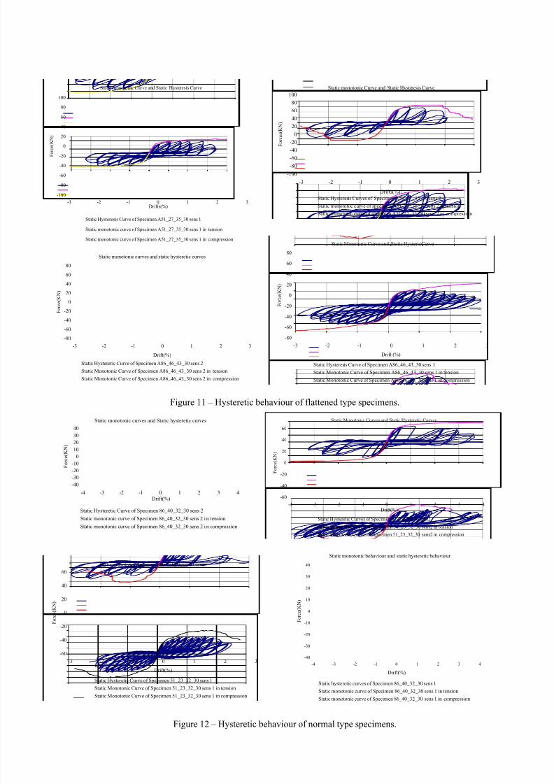
As shown in Table 7 and Table 8, the number of cycles inhysteretic behaviour of flattened expanded metal types and theenergy which is dissipated are greater than that of normaltypes.
It is also observed that out of plane deformations at failure
of normal type specimens are much greater than those offlattened specimens.
As shown in
Figure 11 and Figure 12, pinching effects on the hysteretic
behaviour are much larger for normal type specimens than forflattened type specimens.
VII. SUMMARY OF OBSERVATIONS
An experimental test program has been carried out on smallscale of un-stiffened expanded metal sheet test specimens. Themain objectives of the tests was to calibrate the simple
analytical model for monotonic shear loading that has been proposed by Etienne Pecquet [2] and to study the hysteretic behaviour of expanded metal sheets subjected to shear.
In both monotonic and cyclic phases of the tests all sheetshave buckled at very low shear forces. Some of the specimens(specimens 7 and 8) were globally buckled before testing.
Furthermore it was observed that normal types of EMSs,including specimen 5, 6, 7 and 8 (profiles: 51_23_32_30 and86_40_32_30), buckle more easily than flattened types, whichare specimens 1, 2, 3 and 4 (profiles: A51_27_35_30 andA86_46_43_30).
The first broken bars observed in both monotonic and
cyclic phases of tests are located near one of four corners, thendevelop to the centre of the sheets. Additionally it is easy toobserve that the broken bars are the bars working in tension.There is no bar being locally buckled in monotonic tests.However, in all cyclic tests, many bars have been buckled before being broken. Moreover, in almost cyclic tests, the
maximum shear forces have been attained on the cycle onwhich first broken bar has been observed.
The maximum shear forces of EMSs in monotonic tests aredependent on the voids of the sheets. With nearly the samevoids, ultimate shear forces of flattened type specimens aremuch greater than those of normal types. Nevertheless, it isobserved that maximum displacements of flattened types are
much less than those of normal types and the ductility ofnormal types are much greater than that of flattened types.
The hysteretic loops of all specimens are S-shaped due to pinching effects, but they are stable. The displacement ductilityof all specimens is largely different, ranging from 10 to 20.Pinching effects on all specimens due to yielding in tension and
to buckling in compression caused the degradation of stiffnessof the sheets. In cyclic tests, pinching effects are clear insuccessive cycles beyond the elastic range. In addition, themagnitude of the buckling deformations and deterioration in
stiffness of sheets are increased correspondingly.In all specimens in cyclic test phases, the stiffness of the
sheets is approximately equal to zero during the inversion offorce.
7/21/2019 Behaviour of Expanded Metal Sheets Under Shear Loading
http://slidepdf.com/reader/full/behaviour-of-expanded-metal-sheets-under-shear-loading 7/9
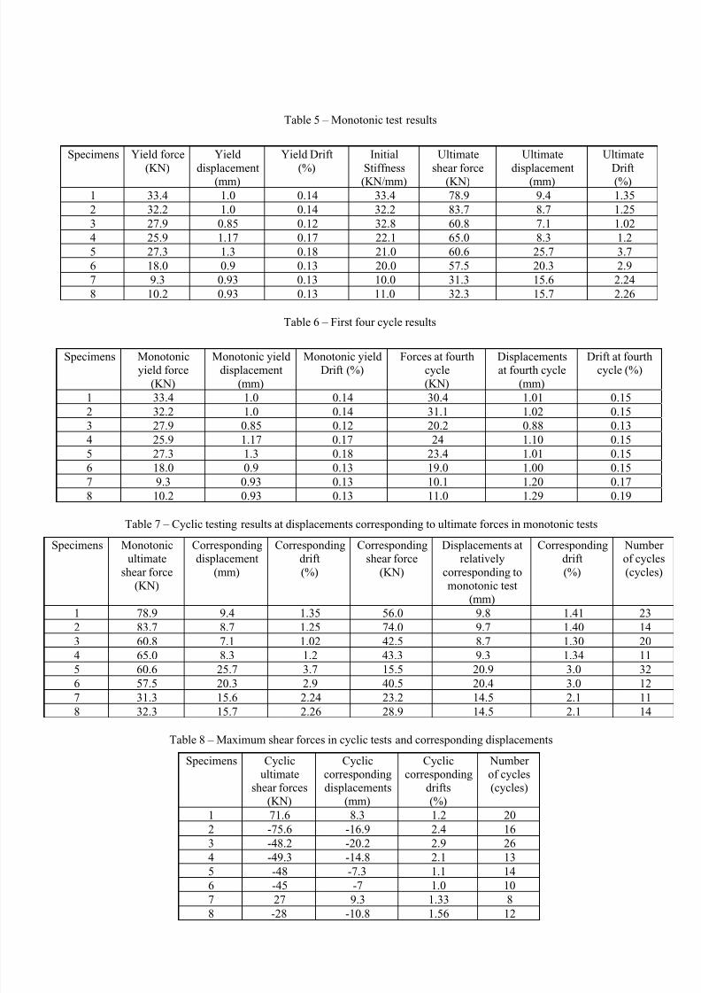
Table 5 – Monotonic test results
Specimens Yield force
(KN)
Yield
displacement(mm)
Yield Drift
(%)
Initial
Stiffness(KN/mm)
Ultimate
shear force(KN)
Ultimate
displacement(mm)
Ultimate
Drift(%)
1 33.4 1.0 0.14 33.4 78.9 9.4 1.35
2 32.2 1.0 0.14 32.2 83.7 8.7 1.25
3 27.9 0.85 0.12 32.8 60.8 7.1 1.02
4 25.9 1.17 0.17 22.1 65.0 8.3 1.2
5 27.3 1.3 0.18 21.0 60.6 25.7 3.7
6 18.0 0.9 0.13 20.0 57.5 20.3 2.9
7 9.3 0.93 0.13 10.0 31.3 15.6 2.24
8 10.2 0.93 0.13 11.0 32.3 15.7 2.26
Table 6 – First four cycle results
Specimens Monotonicyield force
(KN)
Monotonic yielddisplacement
(mm)
Monotonic yieldDrift (%)
Forces at fourthcycle
(KN)
Displacementsat fourth cycle
(mm)
Drift at fourthcycle (%)
1 33.4 1.0 0.14 30.4 1.01 0.15
2 32.2 1.0 0.14 31.1 1.02 0.15
3 27.9 0.85 0.12 20.2 0.88 0.13
4 25.9 1.17 0.17 24 1.10 0.15
5 27.3 1.3 0.18 23.4 1.01 0.15
6 18.0 0.9 0.13 19.0 1.00 0.15
7 9.3 0.93 0.13 10.1 1.20 0.17
8 10.2 0.93 0.13 11.0 1.29 0.19
Table 7 – Cyclic testing results at displacements corresponding to ultimate forces in monotonic tests
Specimens Monotonicultimate
shear force(KN)
Correspondingdisplacement
(mm)
Correspondingdrift
(%)
Correspondingshear force
(KN)
Displacements atrelatively
corresponding tomonotonic test
(mm)
Correspondingdrift
(%)
Numberof cycles
(cycles)
1 78.9 9.4 1.35 56.0 9.8 1.41 23
2 83.7 8.7 1.25 74.0 9.7 1.40 14
3 60.8 7.1 1.02 42.5 8.7 1.30 20
4 65.0 8.3 1.2 43.3 9.3 1.34 11
5 60.6 25.7 3.7 15.5 20.9 3.0 32
6 57.5 20.3 2.9 40.5 20.4 3.0 12
7 31.3 15.6 2.24 23.2 14.5 2.1 118 32.3 15.7 2.26 28.9 14.5 2.1 14
Table 8 – Maximum shear forces in cyclic tests and corresponding displacements
Specimens Cyclicultimate
shear forces(KN)
Cycliccorrespondingdisplacements
(mm)
Cycliccorresponding
drifts(%)
Numberof cycles(cycles)
1 71.6 8.3 1.2 20
2 -75.6 -16.9 2.4 16
3 -48.2 -20.2 2.9 26
4 -49.3 -14.8 2.1 13
5 -48 -7.3 1.1 146 -45 -7 1.0 10
7 27 9.3 1.33 8
8 -28 -10.8 1.56 12
7/21/2019 Behaviour of Expanded Metal Sheets Under Shear Loading
http://slidepdf.com/reader/full/behaviour-of-expanded-metal-sheets-under-shear-loading 8/9
Static monotonic Curve and Static Hysteresis Curve
-100
-80
-60
-40
-20
0
20
40
60
80
100
-3 -2 -1 0 1 2 3
Drifts(%)
F o r c e s ( K N )
Static Hysteresis Curves of Specimen A51_27_35_30 sens 2
Static monotonic curve of specimen A51_27_35_30 sens 2 in tension
Static monotonic curve of specimen A51_27_35_30 sens 2 in compression
Figure 11 – Hysteretic behaviour of flattened type specimens.
Figure 12 – Hysteretic behaviour of normal type specimens.
Static monotonic Curve and Static Hysteresis Curve
-100
-80
-60
-40
-20
0
20
40
60
80
100
-3 -2 -1 0 1 2 3Drifts(%)
F o r c e ( K N )
Static Hysteresis Curve of Specimen A51_27_35_30 sens 1
Static monotonic curve of Specimen A51_27_35_30 sens 1 in tension
Static monotonic curve of Specimen A51_27_35_30 sens 1 in compressionStatic Monotonic Curve and Static HystericCurve
-80
-60
-40
-20
0
20
40
60
80
-3 -2 -1 0 1 2 3
Drift (%)
F o r c e ( K N )
Static Hysteresis Curve of Specimen A86_46_43_30 sens 1
Static Monotonic Curve of Specimen A86_46_43_30 sens 1 in tension
Static Monotonic Curve of Specimen A86_46_43_30 sens 1 in compression
Static monotonic curves and static hysteretic curves
-80
-60
-40
-20
0
20
40
60
80
-3 -2 -1 0 1 2 3
Drift(%)
F o r c e ( K N )
Static Hysteretic Curve of Specimen A86_46_43_30 sens 2
Static Monotonic Curve of Specimen A86_46_43_30 sens 2 in tension
Static Monotonic Curve of Specimen A86_46_43_30 sens 2 in compression
Static monotonic curves and static hysteretic curves
-60
-40
-20
0
20
40
60
-3 -2 -1 0 1 2 3
Drift(%)
F o r c e ( K N )
Static Hysteretic Curve of Specimen 51_23_32_30 sens 1
Static Monotonic Curve of Specimen 51_23_32_30 sens 1 in tension
Static Monotonic Curve of Specimen 51_23_32_30 sens 1 in compression
Static Monotonic Curves and Static Hysteretic Curves
-60
-40
-20
0
20
40
60
-4 -3 -2 -1 0 1 2 3 4Drift(%)
F o r c e ( K N )
Static Hysteretic Curves of Specimen 51_23_32_30 sens2
Static Monotonic Curves of Specimen 51_23_32_30 sens2 in tension
Static Monotonic Curves of Specimen 51_23_32_30 sens2 in compression
Static monotonic behaviour and static hysteretic behaviour
-40
-30
-20
-10
0
10
20
30
40
-4 -3 -2 -1 0 1 2 3 4
Dirft(%)
F o r c e ( K N )
Static hysteretic curves of Specimen 86_40_32_30 sens 1
Static monotonic curve of Specimen 86_40_32_30 sens 1 in tension
Static monotonic curve of Specimen 86_40_32_30 sens 1 in compression
Static monotonic curves and Static hysteretic curves
-40
-30
-20
-10
0
10
20
30
40
-4 -3 -2 -1 0 1 2 3 4
Drift(%)
F o r c e ( K N )
Static Hysteretic Curve of Specimen 86_40_32_30 sens 2
Static monotonic curve of Specimen 86_40_32_30 sens 2 i n tension
Static monotonic curve of Specimen 86_40_32_30 sens 2 i n compression

7/21/2019 Behaviour of Expanded Metal Sheets Under Shear Loading
http://slidepdf.com/reader/full/behaviour-of-expanded-metal-sheets-under-shear-loading 9/9
VIII. CONCLUSIONS1. The correlation between the analytical model and
monotonic tests varies largely different. In some cases, theanalytical model much underestimates the real behaviour of
the EMSs. It may be that only one tension band for the
monotonic behaviour of the sheets is not enough. Thesheets might work in more than one tension band.
2. Because under rather low shear forces the sheets areglobally buckled, the contribution of compression diagonalto the resistance of sheets can be neglected.
3. The degradation in stiffness of the sheets due to pinchingeffects results in a smaller enclosed area under thehysteretic curve and, therefore, a lower amount of energyabsorbed by the system during successive cycles.
4. The deflection required to redevelop the tension field is based on the yielding displacements experienced by the
sheets on the previous cycles.
IX. PERSPECTIVESThe results of the experiments in small scale specimensdescribed above do not fit in all cases with numerical modeland/or analytical formula proposed [2]. This may be due todetrimental effects of weld connections. Furthermore, until
now no proposal for hysteretic behaviour of expanded metalmaterial under shear loading has been made.
The next steps of the research on expanded metal material are1. To improve the analytical model proposed by the study of
Etienne Pecquet.
2. To make numerical simulations on expanded metal sheetsfrom small dimension to large dimension of the sheetsunder cyclic loading and seismic excitations; the simulationshould represent the hysteretic behaviour of expanded metal
sheets.
3. To make additional cyclic tests in small-scale using othersolution for the connection, such as epoxy, glue or buttweld in order.
4. To realise additional tests on large scale expanded metal panel and to check the hysteretic behaviour obtained from
the numerical simulations in that case.5. To model reinforced concrete structures with and without
expanded metal shear panels (EMSP).ACKNOWLEDGEMENTS
This research has been made possible thanks to funding fromthe French Community of Belgium – Macromousse Project andto a funding of the Socialist Republic of Viet Nam.
REFERENCES
1. Métal Déployé Belge s.a, ‘Le catalogue Métal Déployé’,
édition 10/20032. E. Pecquet, S.Cescotto, ‘Mechanical behaviour of expandedmetal sheets: critical and ultimate loads of square andrectangular sheets loaded in shear’, 7th National Congress ontheoretical and Applied Mechanics, May 2006.3. ECCS 1986 - Recommended Testing Procedure for
Assessing the Behaviour of Structural Steel Elements underCyclic Loads