bekomat 33u service unit
TRANSCRIPT

EN - english
Instructions for installation and operation
Replacement unit
Service-Unit BEKOMAT®
33/33 CO/33 F/33 CO F/33U/33U CO/33U F/33U CO F
(SUBM33U / SUBM33UCO / SUBM33UF / SUBM33UCOF)
01
-16
20

2 Service-Unit BEKOMAT® 33/33 CO/33 F/33 CO F/33U/33U CO/33U F/33U CO F

Service-Unit BEKOMAT® 33/33 CO/33 F/33 CO F/33U/33U CO/33U F/33U CO F 3
1 Pictograms and symbols ...................................................................................................................4
2 Safety instructions.............................................................................................................................4
3 Technical data ..................................................................................................................................6
4 Control and maintenance ..................................................................................................................7
5 Elements and components ..............................................................................................................13
6 Recommended spare parts .............................................................................................................14

Pictograms and symbols
4 Service-Unit BEKOMAT® 33/33 CO/33 F/33 CO F/33U/33U CO/33U F/33U CO F
Pos: 1 / Beko Technische Dokum e nt at ion/ Über schr if t en/ 1/ Pikt ogr am m e und Sym bole @ 1\ m od_12907735 95840_ 2901. docx @ 20524 @ 1 @ 1
1 Pictograms and symbolsPos: 2 / Beko Technische Dokum e nt at ion/ Pikt ogr am m e/ Anle it ung beacht en blau @ 0\ m od_12132 683002 55_290 1. docx @ 8336 @ @ 1
Observe the installation and operating instructions
Pos: 3 / Beko Technische Dokum e nt at ion/ Pikt ogr am m e/ Anle it ung beacht en s/ w Typensch ild @ 1\ m od_12907 7218014 2_2901. docx @ 20491 @ @ 1
Observe the installation and operating instructions(on the type plate)
Pos: 4 / Beko Technische Dokum e nt at ion/ Pikt ogr am m e/ G ef ahr War nung Vor sicht s/ w @ 0\ m od_121326568517 4_2901. docx @ 8260 @ @ 1
General danger symbol (danger, warning, caution)
Pos: 5 / Beko Technische Dokum e nt at ion/ Pikt ogr am m e/ G +W+V Net zspannun g s/ w @ 0\ m od_121326619370 1_2901. docx @ 8298 @ @ 1
General danger symbol (danger, warning, caution) for supply voltage and supply voltage-carry-ing plant components
Pos: 6 / Beko Technische Dokum e nt at ion/ Über schr if t en/ 1/ Sicher he it shin weise @ 0\ m od_11836 3760926 1_2901. docx @ 5367 @ 1 @ 1
2 Safety instructionsPos: 7 / Beko Technische Dokum e nt at ion/ Sicher he it / Hin weis An le it ung BEKO ( m ännl. Nam e) @ 0\ m od_11841477875 57_2901. docx @ 5760 @ @ 1
Please check whether or not these instructions correspond to the device type.
Adhere to all advice given in these operating instructions. They include essential informationwhich must be observed during the installation, operation and maintenance. Therefore it is im-perative for the service technician and the responsible operator / technical staff to read theseoperating instructions prior to installation, start-up and maintenance.
The operating instructions must be accessible at any time at the place of application of theBEKOMAT® 33/33 CO .
In addition to these operating instructions, local or national regulations must be complied with,if necessary.
Make sure that the BEKOMAT® 33/33 CO is operated only within the permissible limit valuesindicated on the type plate. Any deviation involves a risk for persons and materials, and mayresult in malfunction and service failures.
If you have any queries regarding these installation- and operating instructions, please contactBEKO TECHNOLOGIES GMBH.
Pos: 8 / Beko Technische Dokum e nt at ion/ Sicher he it / G ef ahr Dr uckluf t @ 0\ m od_118414814385 4_2901. docx @ 5778 @ @ 1
Danger!
Compressed air!
Risk of serious injury or death through contact with quickly or suddenly escaping com-pressed air or through bursting plant components or plant components which are notsecured.
Pos: 9 / Beko Technische Dokum e nt at ion/ Sicher he it / M aßnahm en Dr uckluf t BM @ 0\ m od_118414828429 1_2901. docx @ 5814 @ @ 1
Measures:
• Do not exceed the maximum operating pressure (see type plate).
• Only carry out service measures when the system is pressureless.
• Use pressure-resistant installation material only.
• The feed pipe must be tubed firmly. Discharge pipe: short, fixed pressure hose onto pressure-resistantpipe.
• Make sure that persons or objects cannot be hit by condensate or escaping compressed air.
Pos: 10 / Beko Technische Dok um ent at ion/ Sich er heit / G ef ahr Net zspannung 1 s/ w @ 0\ m od_1184148186948 _2901. docx @ 5796 @ @ 1

Safety instructions
Service-Unit BEKOMAT® 33/33 CO/33 F/33 CO F/33U/33U CO/33U F/33U CO F 5
Danger!
Supply voltage!
There is the risk of an electric shock involving injury or death when coming into contactwith non-insulated components carrying supply voltage.
Pos: 11 / Beko Technische Dok um ent at ion/ Sich er heit / M aßnahm en Net zspann ung BM 31U/ 32U/ 33 U @ 7\ m od_13904671 97804_2 901. docx @ 38043 @ @ 1
Measures:
• During electric installations, all regulations in force need to be adhered to (e.g. VDE 0100 / IEC 60364).
• When the control unit is open, service and installation works must only be undertaken when thesystem is deactivated.
• The removed control unit has no IP degree of protection.
• All types of electrical works must be carried out by authorised and qualified personnel only.
Pos: 12 / Beko Technische Dok um ent at ion/ Sich er heit / Sicher he it shin weis e, weit er e BM ( nicht Ex, nicht I F) @ 0\m od_1183616103 770_29 01. docx @ 4011 @ @ 1
Further safety instructions:
• For installation and operation, the national regulations and safety codes in force must also be adheredto.
• Do not use the BEKOMAT® 33/33 CO in hazardous areas.
• Regarding the inlet screw joints, excessive tightening forces must be avoided. This applies in particularto conical screw joints.
• The BEKOMAT® 33/33 CO will only function when voltage is applied.
• Do not use the test button for permanent drainage.
• Use genuine spare parts only. This is imperative to ensure perfect functioning.Pos: 13 / Beko Technische Dok um ent at ion/ Sich er heit / Zusat z Sicher he it shin weise BM 3 3/ BM 33U @ 0\ m od_1231926 887620_ 2901. docx @ 12830 @ @ 1
Additional advice:
• During installation, use the spanner flat at the feed pipe (wrench size SW28 + 34) as a back rest.
• The service unit must not be dismantled.Pos: 14 / Beko Technische Dok um ent at ion/ Sich er heit / Vor sicht Fehlf unkt i on @ 0\ m od_121437809 6290_29 01. docx @ 9360 @ @ 1
Caution!
Malfunction during operation!
Through incorrect installation and poor maintenance, malfunction may occur at theBEKOMAT .
Condensate which is not discharged may cause damage to plants and in productionprocesses.
Pos: 15 / Beko Technische Dok um ent at ion/ Sich er heit / M aßnahm en Feh lf unkt ionen BM @ 0\ m od_12143784 34025_2 901. docx @ 9379 @ @ 1r
Measures:
• Condensate drainage which is reliable in performance directly optimises the compressed-air quality.
• To prevent damage and breakdowns, it is imperative to observe the following:
• Exact compliance with the specifications of use and with the performance parameters of theBEKOMAT, in connection with the case of application (see "Proper use" section).
• Exact compliance with the installation- and operation instructions in this manual.
• Regular maintenance and control of the BEKOMAT in accordance with the instructions in this oper-ating manual.
Pos: 16 / - -- - Seit enum br uch - -- - @0\ m od_1157028099015_ 0. docx @ 2903 @ @ 1

Technical data
6 Service-Unit BEKOMAT® 33/33 CO/33 F/33 CO F/33U/33U CO/33U F/33U CO F
Pos: 17 / Beko Technische Dok um ent at ion/ Über schr if t en/ 1/ Technisc he Dat en @ 0\ m od_11843295 70967_ 2901. docx @ 6058 @ 1 @ 1
3 Technical dataPos: 18 / Beko Technische Dok um ent at ion/ Techn ische Dat en/ B EKO M AT/ Techn. Dat en BM 3xU + UC + G O ST ( o. Leist g. ) @ 5\m od_1358843578 945_290 1. docx @ 30450 @ @ 1
min./max. operating pressure(see type plate)
0,8...16 bar (12...230 psi)or1,2...16 bar (17...230 psi)
min./max. temperature(see type plate)
+1...+60 °C (+34...+140 °F)or+1...+70 °C (+34...+158 °F)
Condensate inflow Inlet via condensate receiver tank
Condensate outflow G ½ Ø 13 mm hose connector
Condensate oil-contaminated + oil-free
Housing aluminium + plastic, glass fibre-reinforced
Weight (empty) 0,78 kg (1.71 lbs)
Pos: 19 / - -- - Seit enum br uch - -- - @0\ m od_1157028099015_ 0. docx @ 2903 @ @ 1

Control and maintenance
Service-Unit BEKOMAT® 33/33 CO/33 F/33 CO F/33U/33U CO/33U F/33U CO F 7
Pos: 20 / Beko Technische Dok um ent at ion/ Über schr if t en/ 1/ Kont r olle und War t ung @ 0\ m od_118363788 5371_2 901. docx @ 5439 @ 1 @ 1
4 Control and maintenancePos: 21 / Beko Technische Dok um ent at ion/ Sich er heit / G ef ahr Dr uckluf t @ 0\ m od_11841481438 54_2901. docx @ 5778 @ @ 1
Danger!
Compressed air!
Risk of serious injury or death through contact with quickly or suddenly escaping com-pressed air or through bursting plant components or plant components which are notsecured.
Pos: 22 / Beko Technische Dok um ent at ion/ Sich er heit / M aßnahm en Dr uckl uf t BM @ 0\ m od_11841482842 91_290 1. docx @ 5814 @ @ 1
Measures:
• Do not exceed the maximum operating pressure (see type plate).
• Only carry out service measures when the system is pressureless.
• Use pressure-resistant installation material only.
• The feed pipe must be tubed firmly. Discharge pipe: short, fixed pressure hose onto pressure-resistantpipe.
• Make sure that persons or objects cannot be hit by condensate or escaping compressed air.
Pos: 23 / Beko Technische Dok um ent at ion/ Sich er heit / G ef ahr Net zspannung 1 s/ w @ 0\ m od_1184148186948 _2901. docx @ 5796 @ @ 1
Danger!
Supply voltage!
There is the risk of an electric shock involving injury or death when coming into contactwith non-insulated components carrying supply voltage.
Pos: 24 / Beko Technische Dok um ent at ion/ Sich er heit / M aßnahm en Net zspann ung BM 31U/ 32U/ 33 U @ 7\ m od_13904671 97804_2 901. docx @ 38043 @ @ 1
Measures:
• During electric installations, all regulations in force need to be adhered to (e.g. VDE 0100 / IEC 60364).
• When the control unit is open, service and installation works must only be undertaken when thesystem is deactivated.
• The removed control unit has no IP degree of protection.
• All types of electrical works must be carried out by authorised and qualified personnel only.
Pos: 25 / Beko Technische Dok um ent at ion/ Sich er heit / Vor sicht Fehlf unkt i on @ 0\ m od_121437809 6290_29 01. docx @ 9360 @ @ 1
Caution!
Malfunction during operation!
Through incorrect installation and poor maintenance, malfunction may occur at theBEKOMAT .
Condensate which is not discharged may cause damage to plants and in productionprocesses.
Pos: 26 / Beko Technische Dok um ent at ion/ Sich er heit / M aßnahm en Feh lf unkt ionen BM @ 0\ m od_12143784 34025_2 901. docx @ 9379 @ @ 1r
Measures:
• Condensate drainage which is reliable in performance directly optimises the compressed-air quality.
• To prevent damage and breakdowns, it is imperative to observe the following:
• Exact compliance with the specifications of use and with the performance parameters of theBEKOMAT, in connection with the case of application (see "Proper use" section).
• Exact compliance with the installation- and operation instructions in this manual.
• Regular maintenance and control of the BEKOMAT in accordance with the instructions in this oper-ating manual.

Control and maintenance
8 Service-Unit BEKOMAT® 33/33 CO/33 F/33 CO F/33U/33U CO/33U F/33U CO F
Pos: 27 / Beko Technische Dok um ent at ion/ Sich er heit / Hin wei s Vor schr if t en Wer kzeug Rein igung Kon densat Ent sor gung @ 0\ m od_12332396 66823_ 2901. docx @ 13340 @ @ 1
Note:
It is imperative to observe all hazard statements and warnings listed here.
Please also observe all regulations and notes regarding industrial safety and fire prevention at the place ofinstallation.
As a matter of principle, only use suitable and appropriate tools and materials in a proper condition.
Do not use aggressive cleaners and improper devices such as high-pressure cleaners.
Please note that condensates may contain aggressive or harmful components. Therefore, skin contactshould be avoided.
Condensate is subject to mandatory waste disposal. As such, it must be collected in suitable containers, anddisposed of or processed properly.
Pos: 28 / Beko Technische Dok um ent at ion/ War t ung/ BEKO M AT/ War t ung BM 33U Ser vice- Un it ( ohne War t ungsem pf ehlung) @ 6\ m od_13787237672 12_290 1. docx @ 33540 @ @ 1
Maintenance including the cleaning of the conden-sate receiver tank:
1. Avant de remplacer l'unité de maintenance, ilfaut effectuer un reset.L'unité de commande doit être détachée en ap-puyant sur le clip de maintien.Après le retrait, il faut actionner la touche TESTsituée en dessous de la LED, pendant 5 se-condes au moins.
2. Unfasten the BEKOMATfrom the outlet.
3. Detach the BEKOMAT from the tubing at the in-let.
4. Unscrew both M6 cross recessed head screws(22) and remove the service unit (9) by slightlypulling and lifting it.
5. Remove the design shell (11) using a screw-driver.
6. Unscrew the four cover screws (16) and removethe cover (17).
7. Clean the condensate receiver tank (19).

Control and maintenance
Service-Unit BEKOMAT® 33/33 CO/33 F/33 CO F/33U/33U CO/33U F/33U CO F 9
8. Insert new cover O-ring (18) (gasket kit) accord-ing to the diagram.
9. Clean the sealing surfaces of the cover.
10.Put on the cover (17) with the new O-ring andcarefully tighten the four cover screws (16)crosswise (8 Nm).

Control and maintenance
10 Service-Unit BEKOMAT® 33/33 CO/33 F/33 CO F/33U/33U CO/33U F/33U CO F
11.Clean the sealing surfaces (←) at the conden-
sate receiver tank (19).

Control and maintenance
Service-Unit BEKOMAT® 33/33 CO/33 F/33 CO F/33U/33U CO/33U F/33U CO F 11
12.Check whether or not the service unit (9) goeswith the control unit (1) (model designation andcolour of the arresting hook).
13.Check the O-rings at the new service unit (12,13).
14.Mount the design shell (11).
15.Mount the service unit along with the designshell at the condensate receiver tank (19) andtighten both erection bolts (22) (2,5 Nm).
16.Re-install the BEKOMAT at the inlet tubing andoutlet, in reverse order to disassembly.
22
13
19
12 9 11

Control and maintenance
12 Service-Unit BEKOMAT® 33/33 CO/33 F/33 CO F/33U/33U CO/33U F/33U CO F
Control unit with cordpacking
(previous version)
Control unit withoutcord packing
(current version)
Prior to placing a previous version of the controlunit with cord packing (24) in the lower part of thecover, the sealing mat (11) must be removed fromthe service unit.
Installation of the control unit on the BEKOMAT:
1. Check whether or not the service unit (9) goeswith the control unit (1) (model designation andcolour of the arresting hook).
2. Check whether or not the sealing mat (8) andthe contact springs (28) are clean, dry, and freefrom impurities.
3. Introduce the sensor (5) into the service unit (9).
4. Hang the hook (29) of the control unit (1) in theservice unit (9).
5. Press the control unit (1) against the serviceunit (5) and snap into place.
Start-up subsequent to maintenance measures:
Always carry out prior to the start-up:
• Leak test of the screwed connector of the con-densate receiver tank and of the connection ofthis tank to the service unit
• Check of the electrical connections
• Check of the correct engagement of the controlunit
Pos: 29 / - -- - Seit enum br uch - -- - @0\ m od_1157028099015_ 0. docx @ 2903 @ @ 1
Elements and components
Service-Unit BEKOMAT® 33/33 CO/33 F/33 CO F/33U/33U CO/33U F/33U CO F 13
Pos: 30 / Beko Technische Dok um ent at ion/ Über schr if t en/ 1/ Baut eil e und Kom ponent en @ 0\ m od_118363 801435 5_2901. docx @ 5475 @ 1 @ 1
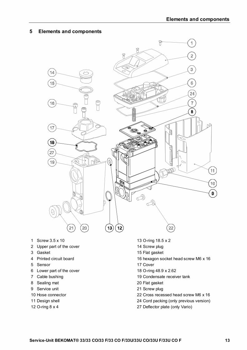
5 Elements and componentsPos: 31 / Beko Technische Dok um ent at ion/ Baut ei le und Kom pone nt en/ BEKO M AT/ Ba ut eile BM 33 U Ser vice- Un it @ 6\ m od_13787272137 54_290 1. docx @ 33574 @ @ 1
1 Screw 3.5 x 10
2 Upper part of the cover
3 Gasket
4 Printed circuit board
5 Sensor
6 Lower part of the cover
7 Cable bushing
8 Sealing mat
9 Service unit
10 Hose connector
11 Design shell
12 O-ring 8 x 4
13 O-ring 18.5 x 2
14 Screw plug
15 Flat gasket
16 hexagon socket head screw M6 x 16
17 Cover
18 O-ring 48.9 x 2.62
19 Condensate receiver tank
20 Flat gasket
21 Screw plug
22 Cross recessed head screw M6 x 16
24 Cord packing (only previous version)
27 Deflector plate (only Vario)
Pos: 32 / - -- - Seit enum br uch - -- - @0\ m od_1157028099015_ 0. docx @ 2903 @ @ 1

Recommended spare parts
14 Service-Unit BEKOMAT® 33/33 CO/33 F/33 CO F/33U/33U CO/33U F/33U CO F
Pos: 33 / Beko Technische Dok um ent at ion/ Über schr if t en/ 1/ Em pf ohlene Er sat zt eil e @ 0\ m od_11836381861 83_290 1. docx @ 5529 @ 1 @ 1
6 Recommended spare partsPos: 34 / Beko Technische Dok um ent at ion/ Er sat zt eile Ver br auchsm at er ia lie n Zubehör / BE KO M AT/ Er sat zt eile BE KO M AT 33U Ser vi ce- Unit ( AU+ FKM ) @ 6\ m od_1378993790 424_290 1. docx @ 34270 @ @ 1
Available sets of spare parts Contents Order number
Service-Unit SUBM33Ufor BM33U or BM33UVor BM33 or BM33V
Service-Unit SUBM33UFfor BM33UF or BM33UVFor BM33F or BM33VF
8, 9, 12, 13
4023633
4023634
Service-Unit SUBM33UCOfor BM33UCO or BM33UVCOor BM33CO or BM33VCO
Service-Unit SUBM33UCOFfor BM33UCOF or BM33UVCOFor BM33COF or BM33VCOF
8, 9, 12, 13
4023635
4023636
Gasket kit 3, 8, 12, 13, 18, (24) 4024397
Design shell 11 4010167
Pos: 35 / Beko Technische Dok um ent at ion/ G lobal e Text e/ Hin weis Üb er set zg. d. O r ig. anleit g. @ 1\ m od_1260433478358_ 2901. docx @ 17104 @ @ 1
Pos: 36 / Beko Technische Dok um ent at ion/ G lobal e Text e/ Hin weis O r igin alan leit ung @ 1\ m od_12604 333462 80_290 1. docx @ 17070 @ @ 1
Pos: 37 / Beko Technische Dok um ent at ion/ G lobal e Text e/ Vor behalt skl ausel @ 0\ m od_12137 040331 53_2901. docx @ 9298 @ @ 1
=== Ende der List e f ür Text m ar keI nhalt ===

Service-Unit BEKOMAT® 33/33 CO/33 F/33 CO F/33U/33U CO/33U F/33U CO F 15
C
Components 13
Control 7
D
Danger compressed air 4, 7
Danger supply voltage 5, 7
Data 6
Degree of protection 5, 7
E
Elements 13
I
Installation and operating instructions 4
Installation and operating instructions 4
Instructions, safety instructions 4
L
Lower part of the cover 13
M
Maintenance 7
Maintenance including the cleaning of thecondensate receiver tank 8
O
Order number 14
P
Pictograms 4
Printed circuit board 13
Q
Qualified personnel 5, 7
R
Recommended spare parts 14
S
Safety instructions 4
Screw plug 13
Sensor 13
Sensor tube plate 12
Service measures 4, 7
Service unit 13
Sets of spare parts 14
Spare parts 5, 14
Symbols 4
T
Technical data 6
U
Upper part of the cover 13

Service-Unit BEKOMAT® 33/33 CO/33 F/33 CO F/33U/33U CO/33U F/33U CO F
Headquarter:
Deutschland / Germany
BEKO TECHNOLOGIES GMBH
Im Taubental 7
D-41468 Neuss
Tel. +49 2131 988 0
中华人民共和国 / China
BEKO TECHNOLOGIES (Shanghai)Co. Ltd.
Rm.606 Tomson Commercial Building
710 Dongfang Rd.
Pudong Shanghai China
P.C. 200122
Tel. +86 21 508 158 85
France
BEKO TECHNOLOGIES S.à.r.l.
Zone Industrielle
1 rue des Frères Rémy
F- 57200 Sarreguemines
Tél. +33 387 283 800
India
BEKO COMPRESSED AIRTECHNOLOGIES Pvt. Ltd.
Plot No.43/1, CIEEP, Gandhi Nagar,
Balanagar, Hyderabad - 500 037, INDIA
Tel. +91 40 23080275
Italia / Italy
BEKO TECHNOLOGIES S.r.l
Via Peano 86/88
I - 10040 Leinì (TO)
Tel. +39 011 4500 576
日本 / Japan
BEKO TECHNOLOGIES K.K
KEIHIN THINK 8 Floor
1-1 Minamiwatarida-machi
Kawasaki-ku, Kawasaki-shi
JP-210-0855
Tel. +81 44 328 76 01
Benelux
BEKO TECHNOLOGIES B.V.
Veenen 12
NL - 4703 RB Roosendaal
Tel. +31 165 320 300
Polska / Poland
BEKO TECHNOLOGIES Sp. z o.o.
ul. Chłapowskiego 47
PL-02-787 Warszawa
Tel +48 22 855 30 95
Scandinavia
www.beko-technologies.com
España / Spain
BEKO Tecnológica España S.L.
Torruella i Urpina 37-42, nave 6
E-08758 Cervello
Tel. +34 93 632 76 68
South East Asia
BEKO TECHNOLOGIES S.E.Asia(Thailand) Ltd.
75/323 Romklao Road
Sansab, Minburi
Bangkok 10510
Thailand
Tel. +66 2-918-2477
臺灣 / Taiwan
BEKO TECHNOLOGIES Co.,Ltd
16F.-5, No.79, Sec. 1,
Xintai 5th Rd., Xizhi Dist.,
New Taipei City 221,
Taiwan (R.O.C.)
Tel. +886 2 8698 3998
Česká Republika / Czech Republic
BEKO TECHNOLOGIES s.r.o.
Na Pankraci 1062/58
CZ - 140 00 Praha 4
Tel. +420 24 14 14 717
United Kingdom
BEKO TECHNOLOGIES LTD.
2 & 3 West Court
Buntsford Park Road
Bromsgrove
GB-Worcestershire B60 3DX
Tel. +44 1527 575 778
USA
BEKO TECHNOLOGIES CORP.
900 Great SW Parkway
US - Atlanta, GA 30336
Tel. +1 404 924-6900
Translation of the original manual/instructions.
Original instructions are in German.
Subject to technical modifications without notice / errors excepted.
BM33U_F_s_unit_uc_manual_en_2014_08.