bending capacity of dry stacked lightweight …
TRANSCRIPT
15th International Brick and Block
Masonry Conference
Florianópolis – Brazil – 2012
BENDING CAPACITY OF DRY STACKED LIGHTWEIGHT
CONCRETE BLOCK MASONRY
Molnár, Miklós1; Jönsson, Johan
2;
1 PhD, Assistant Professor, Lund University, Department of Building and Environmental Technology,
[email protected]; 2 PhD, Assistant Professor, Lund University, Department of Building and Environmental Technology,
Dry stacked light weight concrete block masonry is increasingly used due to its superior
productivity compared to standard block masonry. Low bending capacity parallel to the bed
joints is however a major drawback. This paper presents the results of an experimental study
which has been carried out to improve the bending capacity of dry stacked lightweight
concrete block masonry. The effects of following measures have been studied: 1) the blocks
have been provided with additional holes forming continuous vertical canals and grouted with
concrete; 2) both faces of the dry stacked block masonry have been reinforced with a steel
wire mesh embedded in render. The bending capacity has been determined in four-point
bending tests. Compared to standard dry stacked masonry the bending capacity increased by:
1) 20 % when the additional, continuous vertical canals were filled with concrete grout; 2)
more than five times when steel wire mesh embedded in render was used.
Keywords: bending capacity, dry stacked, lightweight concrete, grouting, steel wire mesh reinforcement
Theme: research and testing
INTRODUCTION
Labor costs constitute a substantial part of the total cost in masonry construction. Dry stacked
lightweight concrete masonry is increasingly used due to considerably higher productivity in
comparison with block masonry laid in mortar, Glitza (1990) and Anand & Ramamurthy
(2003). A major drawback with dry stacking is low bending capacity, especially in bending
parallel to the bed joints. Several existing dry stacked concrete block masonry systems aim at
diminishing this drawback by using a) hollow blocks with interlocking, b) vertical
perforations that are grouted, c) reinforcement placed in vertical holes d) surface bonding
mortars, Murray (2007).
In this paper results from an experimental study carried out to document and improve the
bending capacity of the Swedish NC-blocket, a dry stacked lightweight concrete block
masonry system, are presented.
The studied dry stacking system consists of solid light weight concrete blocks provided with a
central horizontal slot and vertical slot at the header face, see Figure 1. The horizontal slot can
be grouted and reinforced to improve the bending capacity perpendicular to the bed joints.

15th International Brick and Block
Masonry Conference
Florianópolis – Brazil – 2012
Figure 1: Lightweight concrete blocks used for dry stacked masonry – NC-blocket
system
The cavities that form at the header faces of the blocks are filled with concrete grout and
contribute to a locking of the blocks. This grouting also improves the bending capacity
parallel to the bed joints. The bending capacity of the present system is however low and
hinders its wider use.
In the present work two modifications expected to improve the bending capacity have been
studied. In the first case the blocks have been provided with additional holes forming
continuous vertical canals. These vertical canals were subsequently filled with a concrete
grout. In the second case, both faces of the dry stacked block masonry have been rendered and
reinforced with a steel wire mesh embedded in render.
EXPERIMENTAL DETAILS
Lightweight concrete blocks with compressive strength 2,2 N/mm2
have been used for all
specimens. The size and number of specimens in the testing scheme is shown in Table 1.
Table 1: Experimental plan masonry specimens
Series Execution type of masonry specimens Length*height*thickness
l*h*t (mm)
Number of
specimens
I Standard dry stacking (t=190 mm) 885*1000*190 3
II Standard dry stacking (t=400 mm) 900*1000*400 3
III Additional vertical canals grouted with concrete
(t=190 mm, canal diameter 60 mm, spacing 300 mm) 1475*1000*190 5
IV Reinforced render ( t=190 mm+25 mm) 885*1000*215 4
V Reinforced render (t=400 mm+25 mm) 900*1000*425 5
The blocks were 590*200*190 mm and 600*200*400 mm (l*h*t). The masonry specimens
were five courses high and 1,5 blocks long, excepting series 3 where they were 2,5 blocks
long. The specimens were manufactured in the Nyströms Cement factory and transported to
the Lund university laboratory for testing. Testing was carried out 28-30 days after
manufacturing of the specimens.
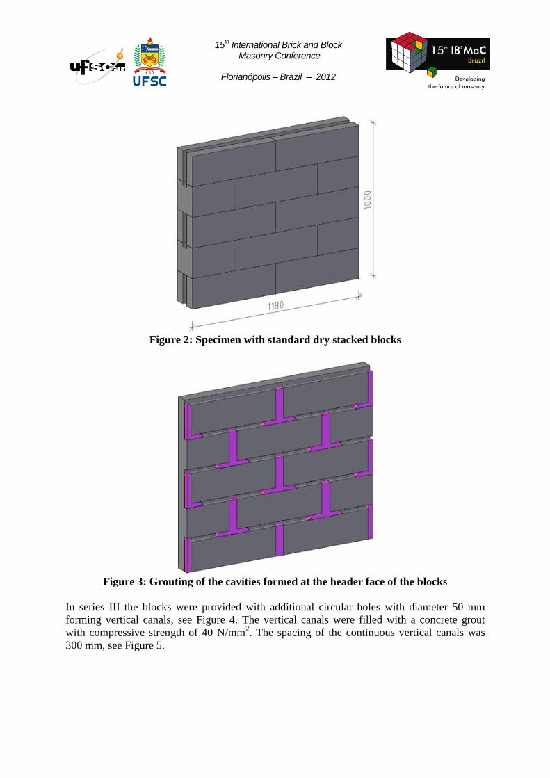
In series I and II (standard specimens) the cavities formed at the end of the blocks were filled
with a concrete grout with compressive strength 30 N/mm2. This grout with low consistency
fills also approximately 100 mm of the horizontal slot, forming a T-shaped body, see Figure 2
and 3. In each course, the spacing of the grouted cavities is 600 mm. The grouting of these
cavities assures that the dry stacked masonry obtains a bending capacity higher than zero.
15th International Brick and Block
Masonry Conference
Florianópolis – Brazil – 2012
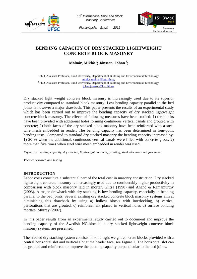
Figure 2: Specimen with standard dry stacked blocks
Figure 3: Grouting of the cavities formed at the header face of the blocks
In series III the blocks were provided with additional circular holes with diameter 50 mm
forming vertical canals, see Figure 4. The vertical canals were filled with a concrete grout
with compressive strength of 40 N/mm2. The spacing of the continuous vertical canals was
300 mm, see Figure 5.

15th International Brick and Block
Masonry Conference
Florianópolis – Brazil – 2012
Figure 4: Blocks with additional circular holes
Figure 5: Series III specimen with grouted vertical canals
Series IV and V consisted of standard specimens provided with a mesh-reinforced render on
both faces. The render consisted of cement lime mortar with compressive strength 5,5 N/mm2
and tensile strength 1,0 N/mm2, Jönsson (2011). The thickness of the render was 15 mm
(exterior face) and 10 mm (interior face).
The reinforcement which was applied centrically in the render consisted of a zinc coated steel
mesh with thread diameter 1,1 mm and mesh spacing of 19 mm. The reinforcement area per
meter of wire-mesh is 50 mm2/m. The tensile strength of the steel threads is 400 N/mm
2.
The bending capacity was determined in four-point bending test in accordance with EN 1052-
2, see Figure 6.

15th International Brick and Block
Masonry Conference
Florianópolis – Brazil – 2012
Figure 6: Test set-up
The load was applied by a hydraulic jack. The force and displacement at mid height of the
specimens were registered.
RESULTS
The specimens failed by formation of a large horizontal crack in either of the two central bed
joints. The failure was quasi-brittle in Series I - II and brittle in series III – V. Typical failure
modes and load-mid-span deformation curves for standard dry stacked and rendered mesh-
reinforced specimens are shown in Figures 7-8.
Figure 7: Typical failure mode for dry stacked masonry in bending – series I
15th International Brick and Block
Masonry Conference
Florianópolis – Brazil – 2012
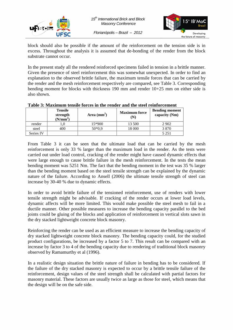
Figure 8: Load-mid-span deformation curves for rendered reinforced specimens – Series
IV
The maximum bending moments Mu obtained in the tests are shown in Table 2.
Table 2: Results of the flexural tests
Specimens Maximum bending
moment Mu (Nm/m)
Mean
(Nm/m)
C.V.
(%)
Formal flexural
strength fx1 (N/mm2)
Series I - Standard dry stacking,
t=190 mm
651
682 4 0,11 690
704
Series II - Standard dry stacking,
t=400 mm
2 598
1 989 29 0,07 1 436
1 932
Series III -Additional vertical
canals grouted with concrete
(t=190 mm, canal diameter 60
mm, spacing 300 mm)
831
769 9 0,13
821
753
656
782
Series IV - Reinforced render
( t=190 mm+25 mm)
5 138
5 251 3 0,68 5 138
5 337
5 390
Series V - Reinforced render
(t=400 mm+25 mm)
10 164
10 367 3 0,34
10 291
10 767
10 544
10 070
The formal flexural strength was calculated dividing the maximum bending moment with the
elastic section modulus.

15th International Brick and Block
Masonry Conference
Florianópolis – Brazil – 2012
ANALYSIS AND DISCUSSION
The bending capacity parallel to bed joints of dry stacked masonry without any grouting is
close to zero, Uzoegbo and Ngowi (2004). Grouting of the vertical slots at the header face of
the blocks gives rise to a certain bonding between the dry stacked block courses. This bonding
resulted in formal flexural strength values amounting to 0,07 – 0,11 N/mm2.
From a phenomenological point of view it is however questionable to use flexural strength to
characterize transversal load resistance capacity of dry stacked masonry. During bending a
force couple is formed between the edge (compression) and the grout in the cavities formed
by the slots (tension). The bending capacity depends on the tensile force that can be resisted
by the grouted slots and the lever arm.
Specimens in series I and III have the same cross section but different amount of grouted
cavities. In series I the number of grouted cavities per meter length is 3, while in series III
their number is 4. According to the mentioned force transfer mechanism, the bending capacity
of series III should be approximately 4/3 = 1,33 times larger than in series I. The observed
difference in bending capacity from the tests is 769/682 = 1,13, see Table 2. The lower
bending capacity observed in the tests might be caused by high water absorption of the blocks
and not entirely filled slots.
The effect of grouted slots and holes is dependent on the tensile strength of the concrete used
as grout. The theoretical cross section area of the grouted slots and holes is approximately
2000 mm2 per slot/hole. The tensile stress σt at the contact surface at failure can be
approximated from:
(1)
where Mu is the bending moment, Agrout is the cross section of the grouted area and z is the
cantilever arm. Using the results from series I the mean value of the bending moment is
Mu=682 Nm/m, the lever arm z=0,190/2=0,095 m and the number of grouted slots 3. For this
case the tensile stress at failure at the contact surface is calculated to σt = 1,3 N/mm2. This
value is lower than the expected mean tensile strength of the concrete grout (for concrete C30
fctm = 2,9 N/mm2). As mentioned above, the difference might depend on difficulties to fill the
cavities entirely with grout, which results in lower cross section area than assumed.
Considering these factors, the correspondence between experimentally deduced and
theoretical bending capacity seems reasonable.
In absolute terms the increase of the bending capacity due to grouting of additional vertical
holes is limited. More substantial increase of the bending capacity should be possible by
increasing the bonding area by providing the blocks with larger slots and holes. Another
possibility is to place vertical reinforcement in the continuous vertical canals.
When dry stacked block masonry is provided with mesh-reinforcement embedded in the
render at both faces of the blocks, the main contribution to the flexural strength is obtained
from a force couple formed between the compressed and tensioned faces of the masonry. The
flexural strength will in this case depend on the tensile strength of the render and
reinforcement. A failure mode implying crushing of the compressed render and parts of the
15th International Brick and Block
Masonry Conference
Florianópolis – Brazil – 2012
block should also be possible if the amount of the reinforcement on the tension side is in
excess. Throughout the analysis it is assumed that de-bonding of the render from the block
substrate cannot occur.
In the present study all the rendered reinforced specimens failed in tension in a brittle manner.
Given the presence of steel reinforcement this was somewhat unexpected. In order to find an
explanation to the observed brittle failure, the maximum tensile forces that can be carried by
the render and the mesh reinforcement respectively are compared, see Table 3. Corresponding
bending moment for blocks with thickness 190 mm and render 10+25 mm on either side is
also shown.
Table 3: Maximum tensile forces in the render and the steel reinforcement
Tensile
strength
(N/mm2)
Area (mm2)
Maximum force
(N)
Bending moment
capacity (Nm)
render 1,0 15*900 13 500 2 902
steel 400 50*0,9 18 000 3 870
Series IV 5 251
From Table 3 it can be seen that the ultimate load that can be carried by the mesh
reinforcement is only 33 % larger than the maximum load in the render. As the tests were
carried out under load control, cracking of the render might have caused dynamic effects that
were large enough to cause brittle failure in the mesh reinforcement. In the tests the mean
bending moment was 5251 Nm. The fact that the bending moment in the test was 35 % larger
than the bending moment based on the steel tensile strength can be explained by the dynamic
nature of the failure. According to Ansell (2006) the ultimate tensile strength of steel can
increase by 30-40 % due to dynamic effects.
In order to avoid brittle failure of the tensioned reinforcement, use of renders with lower
tensile strength might be advisable. If cracking of the render occurs at lower load levels,
dynamic affects will be more limited. This would make possible the steel mesh to fail in a
ductile manner. Other possible measures to increase the bending capacity parallel to the bed
joints could be gluing of the blocks and application of reinforcement in vertical slots sawn in
the dry stacked lightweight concrete block masonry.
Reinforcing the render can be used as an efficient measure to increase the bending capacity of
dry stacked lightweight concrete block masonry. The bending capacity could, for the studied
product configurations, be increased by a factor 5 to 7. This result can be compared with an
increase by factor 3 to 4 of the bending capacity due to rendering of traditional block masonry
observed by Ramamurthy et al (1996).
In a realistic design situation the brittle nature of failure in bending has to be considered. If
the failure of the dry stacked masonry is expected to occur by a brittle tensile failure of the
reinforcement, design values of the steel strength shall be calculated with partial factors for
masonry material. These factors are usually twice as large as those for steel, which means that
the design will be on the safe side.

15th International Brick and Block
Masonry Conference
Florianópolis – Brazil – 2012
To facilitate transportation between the factory and the laboratory, the height of the specimens
was limited to five courses, which is the lowest number of courses allowed by the test method
EN-1052-2. Accordingly, the slenderness ratio of the specimens was 5,3 respectively 2,5
which is not optimal for bending tests. Arching effects due to the short span might have
resulted in an overestimation of the bending capacity. In the optimal case the slenderness ratio
should have been chosen larger than 6. This circumstance might be taken into consideration
when test results are used in design. More stringent requirements concerning the lowest
admissible slenderness ratios should be introduced in EN-1052-2.
CONCLUSIONS
In this work, dry stacked lightweight concrete block masonry has been tested in bending
parallel to the bed joints. The objective of the work was to study and quantify the effects of
additional grouting and of surface reinforcement embedded in render on the bending capacity
parallel to bed joints. Main findings and conclusions:
- Providing light weight concrete blocks with additional smaller holes that can be filled
with concrete grout has a positive, though limited effect. Larger increase in bending
capacity can be expected if larger continuous cavities are provided and filled with
concrete grout. This measure may however result in increased costs and lower thermal
insulation.
- Surface reinforcement of steel wire mesh embedded in render is an efficient measure
to increase the bending capacity parallel to the bed joints.
- When renders with high tensile strength are used, dynamic effects will result in a
brittle failure of the steel mesh. In practical design partial factors accounting for brittle
failure should be used.
- Using renders with lower tensile strength can limit dynamic effects allowing the steel
mesh reinforcement to fail in a ductile manner. Smaller crack width would be an
additional positive effect.
- The bending capacity of rendered reinforced dry stack masonry parallel to bed joints
can be anticipated by using a force couple analogy and knowledge about wall
geometry and tensile strength of the render and mesh reinforcement.
ACKNOWLEDGEMENTS
The research was carried out with financial support from Nyströms Cement AB. Arne Cajdert
from AC Byggkonsult contributed with technical advice during planning of the tests. All
contributions are kindly acknowledged.
REFERENCES
Anand, K. B. and Ramamurthy. K., "Laboratory-Based Productivity Study on Alternative
Masonry Systems", Journal of Construction Engineering and Management, Vol. 129, No 3
(2003), pp 237-242.

15th International Brick and Block
Masonry Conference
Florianópolis – Brazil – 2012
Ansell, A. ”Dynamic testing of steel for new type of energy absorbing rock bolt”, the Journal
of Constructional Steel Research, 62, 2006, pp 501-512.
EN 1052-2 “Methods for test of masonry – Part 2: Determination of flexural strength”,
Swedish Institute of Standards, 2000.
Jönsson, J. “Analysis of parameters influencing cracking of renders”, Research report (draft),
Lund University, Lund, Sweden, 2011.
Glitza, H. ”State of the art and tendency of development of masonry without mortar” (in
German), Proceedings of the 9th International Brick/Block Masonry Conference, Berlin,
Germany, 13-16 October 1991, Vol. 2, pp 1028-1033.
Murray, E.B. ”Dry stacked surface bonded masonry – structural testing and evaluation”, MSc
thesis, Brigham Young University, USA, 2007.
http://contentdm.lib.byu.edu/ETD/image/etd2188.pdf, accessed 2011-08-04.
Ramamurthy, K., Radhakrishnan, R. and Rajasekhar, G. “Flexural strength behavior normal
to bed joint of plastered concrete block masonry”, Masonry International, Vol. 9, No. 3, 1996,
pp 91-94.
Uzoegbo, H.C. and Ngowi, J.V. ”Lateral strength of a dry-stack wall system”, Masonry
International, Vol. 17, No. 3, 2004, pp 122-128.