bending modes, elastic constants and mechanical stability
TRANSCRIPT
C A R B O N 4 9 ( 2 0 1 1 ) 6 2 – 6 9
. sc iencedi rec t .com
avai lab le at wwwjournal homepage: www.elsev ier .com/ locate /carbon
Bending modes, elastic constants and mechanical stabilityof graphitic systems
G. Savini a,b,*, Y.J. Dappe c, S. Oberg d, J.-C. Charlier e, M.I. Katsnelson a, A. Fasolino a
a Institute for Molecules and Materials, Radboud University Nijmegen, 6525ED Nijmegen, The Netherlandsb Department of Engineering, University of Cambridge, CB3 0FA Cambridge, United Kingdomc Institut de Physique et Chimie des Materiaux, CNRS, F-67034 Strasbourg, Franced Department of Mathematics, Lulea University of Technology, S-97187 Lulea, Swedene Institute of Condensed Matter and Nanosciences (IMCN), Universite Catholique de Louvain, Place Croix du Sud 1 (NAPS-Boltzmann), B-1348
Louvain-la-Neuve, Belgium
A R T I C L E I N F O A B S T R A C T
Article history:
Received 9 July 2010
Accepted 18 August 2010
Available online 24 August 2010
0008-6223/$ - see front matter � 2010 Elsevidoi:10.1016/j.carbon.2010.08.042
* Corresponding author at: Department of En748348.
E-mail address: [email protected] (G. Sav
The thermodynamic and mechanical properties of graphitic systems are strongly depen-
dent on the shear elastic constant C44. Using state-of-the-art density functional calcula-
tions, we provide the first complete determination of their elastic constants and
exfoliation energies. We show that stacking misorientations lead to a severe lowering of
C44 of at least one order of magnitude. The lower exfoliation energy and the lower C44 (more
bending modes) suggest that flakes with random stacking should be easier to exfoliate than
the ones with perfect or rhombohedral stacking. We also predict ultralow friction behav-
iour in turbostratic graphitic systems.
� 2010 Elsevier Ltd. All rights reserved.
1. Introduction tic constant C44 affects the mechanism of exfoliation that is
Graphitic systems are used for a wide variety of industrial
applications, ranging from lubricant and refractory materials
to neutron moderators in nuclear fission reactors [1] and plas-
ma shields in the next generation of fusion reactors [2,3]. The
recent realization of graphene [4] (single graphitic layer) and
the discovery of its unusual electronic properties [5,6] have
raised the interest on flake graphitic systems as a route to pro-
duce graphene samples of high quality and in large scale [7–9].
Despite the technological and scientific importance of gra-
phitic systems, the knowledge of their elastic properties is
unexpectedly poor and new insights are needed. The values
of the elastic constants describe the mechanical behaviour
[10] and are decisive in engineering design to avoid material
failure. In layered materials, they are even more important
for the thermodynamic properties due to a low-lying branch
of acoustic vibrations, the bending modes, predicted by Lif-
shitz [11] over 50 years ago. Here we show that the shear elas-
er Ltd. All rights reserved
gineering, University of
ini).
relevant for the production of graphene.
The most reliable experimental studies of the elastic con-
stants have been obtained by inelastic X-ray scattering [12]
and ultrasonic, sonic resonance, and static test methods [13].
The sample used in the first study [12] was single-crystalline
Kish graphite, characterized by an extraordinary high degree
of ordering, the closest approximation to the perfect AB
stacking graphite (hex-g). The second study [13] was done
using highly oriented pyrolitic graphite, the closest approxi-
mation to turbostratic graphite (turbo-g) where the graphitic
layers are randomly oriented around the c-axis.
Except for C44 and C13, both studies are in agreement with-
in the experimental uncertainties. The C13 value in turbo-g
was determined only by the less accurate static test method
and it may be affected by errors. Conversely, C44 in turbo-g
was determined from the sound velocity and its value ranges
between 0.18 and 0.35 GPa [13], one order of magnitude lower
than 5.0 ± 3 GPa found in hex-g [12].
.
Cambridge, CB3 0FA Cambridge, United Kingdom. Fax: +44 1223
C A R B O N 4 9 ( 2 0 1 1 ) 6 2 – 6 9 63
The discrepancy on C44 is attributed to the existence of
mobile basal dislocations [13,14]. After neutron irradiation,
the elastic constant C44 increases by up to an order of magni-
tude [14], suggesting that interstitial defects [15] could pin the
dislocation motions, whence the intrinsic value of C44 is mea-
sured. A principal difficulty with this explanation is that
interstitial atoms inevitably increase the shear resistance be-
tween graphitic layers and therefore they may increase the
C44 value by themselves.
The aim of this study is to investigate from first principles
the elastic constants of graphitic systems with respect to the
stacking misorientations between layers, and to describe the
key role of the shear elastic constant C44 on the bending
modes (thermal property) and mechanical stability. We show
that stacking misorientations greatly affect C44 and that gra-
phitic systems with perfect (hex-g) and random (turbo-g)
stacking should be considered as two distinct materials de-
scribed by their own elastic and thermodynamic properties.
This paper is structured as follow. In Section 2, we give a
brief summary of the theoretical methods and a discussion
of the LCAO-S2 + vdW formalism to include the long-range
van der Waals (vdW) interactions. The consequences of shear
elastic constant C44 on the bending modes and mechanical
stability are shown in Sections 3.1 and 3.2, respectively.
The elastic constants in the case of high-symmetric sys-
tems (hexagonal, orthorhombic, rhombohedral and AA hex-
agonal stackings) and for graphitic layers randomly oriented
around the c-axis (turbostratic stacking) are presented in Sec-
tions 3.3 and 3.4, respectively.
Finally, we summarize and comment on our results
(Section 4).
2. Method
All the calculations are performed using density functional
theory, within the local density approximation scheme (LDA),
norm-conserving pseudopotentials [16] and plane waves with
cut-off energy of 150 Ry (ABINIT package [17]). The k-point
mesh was chosen so that the average density corresponds
approximately to a 32 · 32 · 16 mesh for hex-g. Energies were
converged within 0.05 meV/atom, and elastic constants within
0.5%. For large supercells (turbo-g with more than 50 atoms) we
have used localized basis-set composed of Gaussian orbitals
(AIMPRO code [18]). The elastic constants calculated by the
two LDA codes are in agreement within 3% or better.
The choice of LDA is not fortuitous [19] and it was dictated
by test calculations using the generalized-gradient approxi-
mation (GGA) within the Perdew–Burke–Ernzerhof scheme
[20]. According to GGA, the distance between graphitic layers
is far too large (4.2 A), resulting in a negligible interlayer bind-
ing energy and almost vanishing out-of-plane elastic con-
stants (C44;C33). For these reasons we have dismissed the
use of GGA from this study [21–23].
Even though LDA yields accurate equilibrium distances,
due to energetical error compensations, the long-range van
der Waals (vdW) and more generally the weak contribution
to the out-of-plane interactions is not well described [24,25].
In order to check the importance of these effects on
C44 and C33, we have used the LCAO-S2 + vdW formalism to
include these specific interactions within LDA [26] (using
FIREBALL code [27]).
This formalism takes into account two major contribu-
tions. The first one, which we call weak chemical interaction,
is a repulsive energy originating from the overlaps of elec-
tronic densities between the weakly interacting subsystems.
Even though the overlaps are rather small, this energy is
not negligible. This contribution is evaluated proceeding to
a second order expansion of the electronic wavefunctions
with respect to the overlaps.
The second contribution, which is the vdW itself, originat-
ing from charge fluctuations, can be seen as the interaction be-
tween electronic dipoles. In the frame of the dipolar
approximation, we use a second order perturbation theory to
describe this contribution. This method has originally been
tested with success on standard graphene–graphene interac-
tion, and more recently on a wide range of graphitic materials
[28]. In its current stage, the analysis of the internal stresses
is not implemented yet, thus the elastic constants that change
the in-plane bond lengths (C11; C12; C13) are overestimated by
up to 15%. However, for C44 and C33 that describe the weak
interaction between layers, the internal stresses are negligible,
and the calculated values are expected to be very accurate.
The elastic constants are determined using two different
approaches. The first one uses the response-function, imple-
mented in the ABINIT code, to calculate the second derivative
of the total energy with respect to the strains.
The second approach uses the elastic energy density [29].
For each elastic constant we have applied 21 strain compo-
nents eij to the equilibrium crystal structures (eij were typically
ranging between ±0.01 with increments 0.001). The elastic
constants are found by fitting the calculated energies to a
polynomial function in the strains. Both approaches yield re-
sults in agreement within 0.2%.
3. Results and discussion
3.1. Bending modes
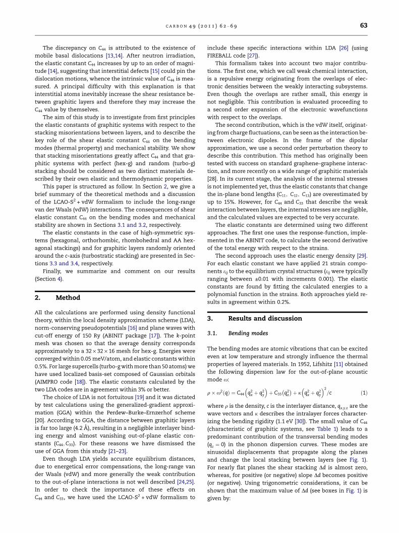
The bending modes are atomic vibrations that can be excited
even at low temperature and strongly influence the thermal
properties of layered materials. In 1952, Lifshitz [11] obtained
the following dispersion law for the out-of-plane acoustic
mode x:
q� x2 qð Þ ¼ C44 q2x þ q2
y
� �þ C33 q2
z
� �þ j q2
x þ q2y
� �2
=c ð1Þ
where q is the density, c is the interlayer distance, qx;y;z are the
wave vectors and j describes the intralayer forces character-
izing the bending rigidity (1.1 eV [30]). The small value of C44
(characteristic of graphitic systems, see Table 1) leads to a
predominant contribution of the transversal bending modes
(qz ¼ 0) in the phonon dispersion curves. These modes are
sinusoidal displacements that propagate along the planes
and change the local stacking between layers (see Fig. 1).
For nearly flat planes the shear stacking Dd is almost zero,
whereas, for positive (or negative) slope Dd becomes positive
(or negative). Using trigonometric considerations, it can be
shown that the maximum value of Dd (see boxes in Fig. 1) is
given by:
d > 0Δ ΔΔ d < 0 Δ Δ d > 0
(a) (b) (c) (d) (a)
≅ 0dd ≅ 0
−Δ+Δd d
(b) (d)(c)(a)
Fig. 1 – Transversal acoustic (bending) mode. The bending changes the local stacking between graphitic layers. The boxes
(a–d) show regions with different slopes and stackings. The shear Dd gives the deviations from AB phase (perfect stacking).
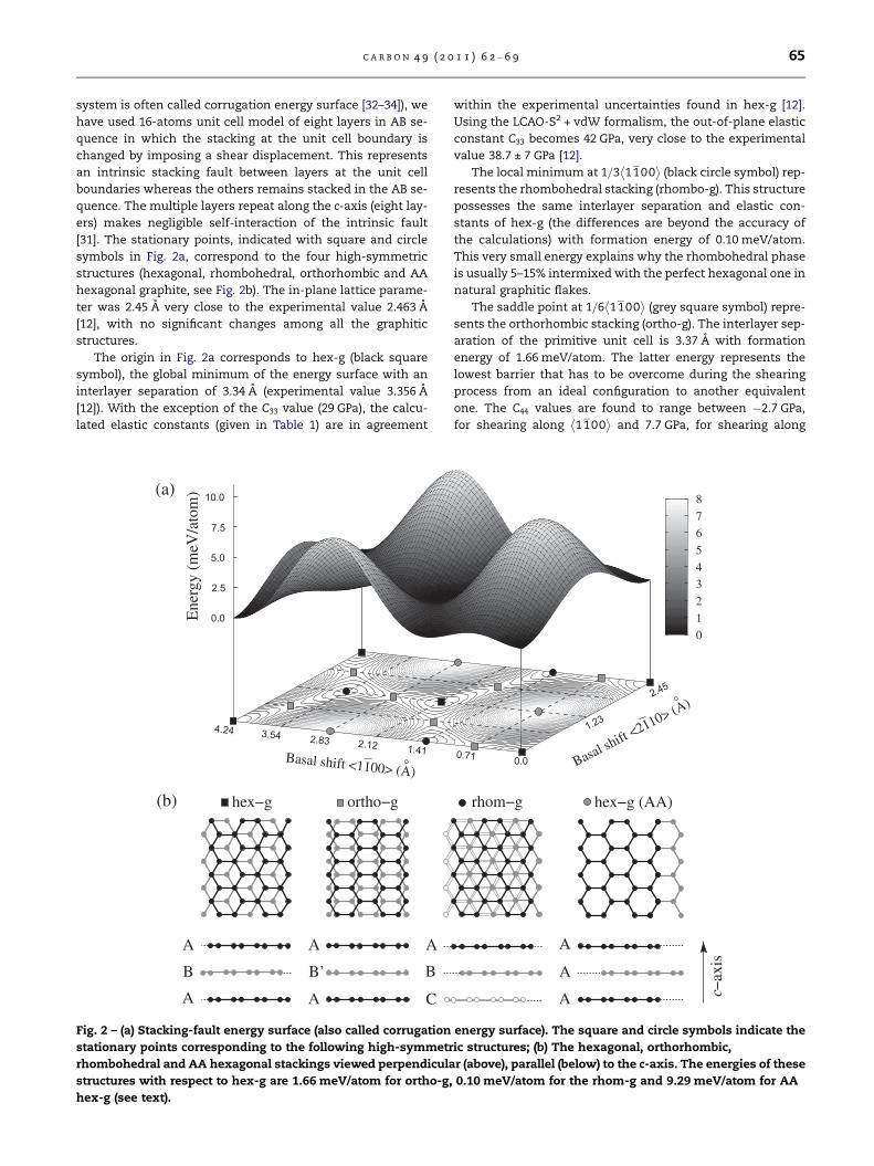
Table 1 – Elastic constants in unit of GPa for the different graphitic systems. The values between brackets are calculated usingthe van der Waals correction. These results show that the C13 values do not significantly change between turbo-g and hex-gand we propose that the same value 0 ± 3 GPa should be appropriate also for turbostratic stacking. The shear elastic constantsC44 found in turbostratic stacking correspond to commensurate structures of area ranging between 36 and 563 A2.
C11 C12 C33 C13 C44
Hex-g (AB) Exp. [12] 1109 ± 16 139 ± 36 38.7 ± 7 0 ± 3 5.0 ± 3.0Theory 1109 175 29 (42) �2.5 4.5 (4.8)
Turbo-g Exp. [13] 1060 ± 20 180 ± 20 36.5 ± 1 15 ± 5 0.18/0.35Theory 1080 ± 3 171 ± 4 27 ± 2 (36 ± 1) �2.7 ± 1 0.16/0.31 (0.19/0.34)
Rhombo-g Theory 1107 175 29 (42) �2.5 4.4 (4.8)Ortho-g Theory 1095 173 26 (38) �2.6 �2.7/7.7 (�2.9/7.3)Hex-g (AA) Theory 1028 162 21 (30) �3.0 �3.8 (�3.8)
64 C A R B O N 4 9 ( 2 0 1 1 ) 6 2 – 6 9
Dd ¼ pack� 1ffiffiffiffiffiffiffiffiffiffiffiffiffiffiffiffiffiffiffiffi
1þ 2pak
� �2q ð2Þ
where a is the amplitude, k is the wavelength and c is the
interlayer distance. The crystal resistance to the stacking
shear [29] is proportional to E / C44 � Dd2; and by lowering
C44 more bending modes can be excited at lower temperature.
In the limit of C44 ¼ 0, graphitic systems approach the graph-
ene behaviour, where indeed bending modes (or ripples) are
always present [30].
3.2. Mechanical stability
By imposing the elastic strain energy as positively definite
[29], the stability conditions are given by:
2C213 < C33 C11 þ C12ð Þ and C11;C12;C33;C44 > 0 ð3Þ
Note that C13 does not affect the stability: a positive (or
negative) value means that under in-plane compression the
out-of-plane distance tends to expand (or contract).
The elastic constants C11; C12 describe in-plane deforma-
tions and they possess the highest values due to the strong
sp2 bonding interactions within the graphene planes. The
elastic constant C33 describes out-of-plane compression or
expansion and it has always a positive value for perfect and
stacking misorientations (see Table 1).
The elastic constant C44 corresponds to a shear between
graphene layers. Due to the weak interaction between planes,
the C44 value is the lowest and can be positive or negative
depending on the stacking misorientations (see Table 1).
The latter elastic constant is the only one that can break
the mechanical stability condition (i.e. C44 < 0).
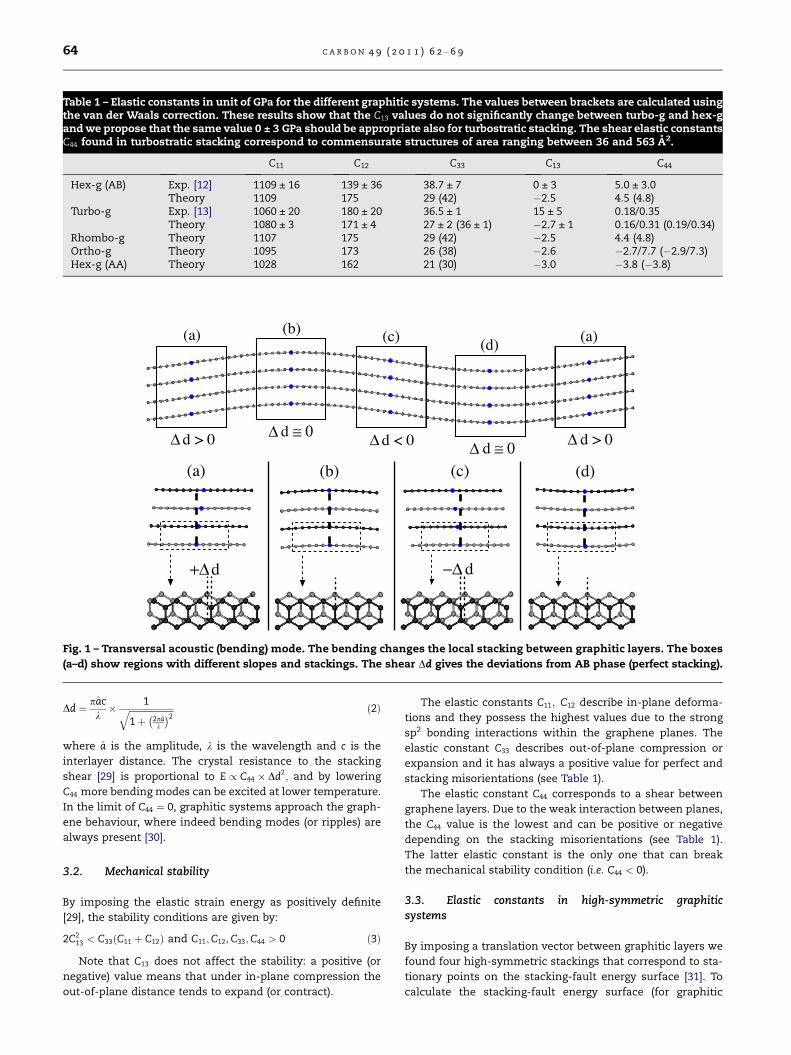
3.3. Elastic constants in high-symmetric graphiticsystems
By imposing a translation vector between graphitic layers we
found four high-symmetric stackings that correspond to sta-
tionary points on the stacking-fault energy surface [31]. To
calculate the stacking-fault energy surface (for graphitic
C A R B O N 4 9 ( 2 0 1 1 ) 6 2 – 6 9 65
system is often called corrugation energy surface [32–34]), we
have used 16-atoms unit cell model of eight layers in AB se-
quence in which the stacking at the unit cell boundary is
changed by imposing a shear displacement. This represents
an intrinsic stacking fault between layers at the unit cell
boundaries whereas the others remains stacked in the AB se-
quence. The multiple layers repeat along the c-axis (eight lay-
ers) makes negligible self-interaction of the intrinsic fault
[31]. The stationary points, indicated with square and circle
symbols in Fig. 2a, correspond to the four high-symmetric
structures (hexagonal, rhombohedral, orthorhombic and AA
hexagonal graphite, see Fig. 2b). The in-plane lattice parame-
ter was 2.45 A very close to the experimental value 2.463 A
[12], with no significant changes among all the graphitic
structures.
The origin in Fig. 2a corresponds to hex-g (black square
symbol), the global minimum of the energy surface with an
interlayer separation of 3.34 A (experimental value 3.356 A
[12]). With the exception of the C33 value (29 GPa), the calcu-
lated elastic constants (given in Table 1) are in agreement
B
A
A
B’
A
A
A
B
C
ortho−ghex−g
2.5
0.0
5.0
7.5
10.0
1.412.122.83
3.544.24
(a)
(b)
Ene
rgy
(meV
/ato
m)
Basal shift <1100> (A)
Fig. 2 – (a) Stacking-fault energy surface (also called corrugation
stationary points corresponding to the following high-symmetr
rhombohedral and AA hexagonal stackings viewed perpendicula
structures with respect to hex-g are 1.66 meV/atom for ortho-g,
hex-g (see text).
within the experimental uncertainties found in hex-g [12].
Using the LCAO-S2 + vdW formalism, the out-of-plane elastic
constant C33 becomes 42 GPa, very close to the experimental
value 38.7 ± 7 GPa [12].
The local minimum at 1=3 1100� �
(black circle symbol) rep-
resents the rhombohedral stacking (rhombo-g). This structure
possesses the same interlayer separation and elastic con-
stants of hex-g (the differences are beyond the accuracy of
the calculations) with formation energy of 0.10 meV/atom.
This very small energy explains why the rhombohedral phase
is usually 5–15% intermixed with the perfect hexagonal one in
natural graphitic flakes.
The saddle point at 1=6 1100� �
(grey square symbol) repre-
sents the orthorhombic stacking (ortho-g). The interlayer sep-
aration of the primitive unit cell is 3.37 A with formation
energy of 1.66 meV/atom. The latter energy represents the
lowest barrier that has to be overcome during the shearing
process from an ideal configuration to another equivalent
one. The C44 values are found to range between �2.7 GPa,
for shearing along 1100� �
and 7.7 GPa, for shearing along
0
1
2
3
4
5
6
7
8
hex−g (AA)
A
A
A
rhom−g
1.23
2.45
0.71 0.0 Basal shift <
2110> (A)
−ax
isc
energy surface). The square and circle symbols indicate the
ic structures; (b) The hexagonal, orthorhombic,
r (above), parallel (below) to the c-axis. The energies of these
0.10 meV/atom for the rhom-g and 9.29 meV/atom for AA
66 C A R B O N 4 9 ( 2 0 1 1 ) 6 2 – 6 9
the 2110� �
axis. No significant changes are found for the
other elastic constants (see Table 1). Although unstable (due
to the negative C44), this structure acts as an intermediate
phase during the transformation from graphite to diamond
[35].
The global maximum at 2=3 1100� �
(grey circle symbol)
corresponds to AA hexagonal stacking (AA hex-g). This
phase has the largest interlayer separation (3.60 A) and the
highest formation energy (9.29 meV/atom). Its elastic con-
stants are smaller than in hex-g, and C44 in particular, be-
comes negative (�3.8 GPa) breaking the stability conditions.
Even though this structure is highly unstable, a recent study
has suggested that screw dislocations locally encourage this
stacking [36].
: s
0.0
2.0
1.0
7.0810.61
14.1517.69
21.23
Ene
rgy
(meV
/ato
m)
Basal shift <1100> (A)
(c)
=38.21θ
(2,1)
(a)
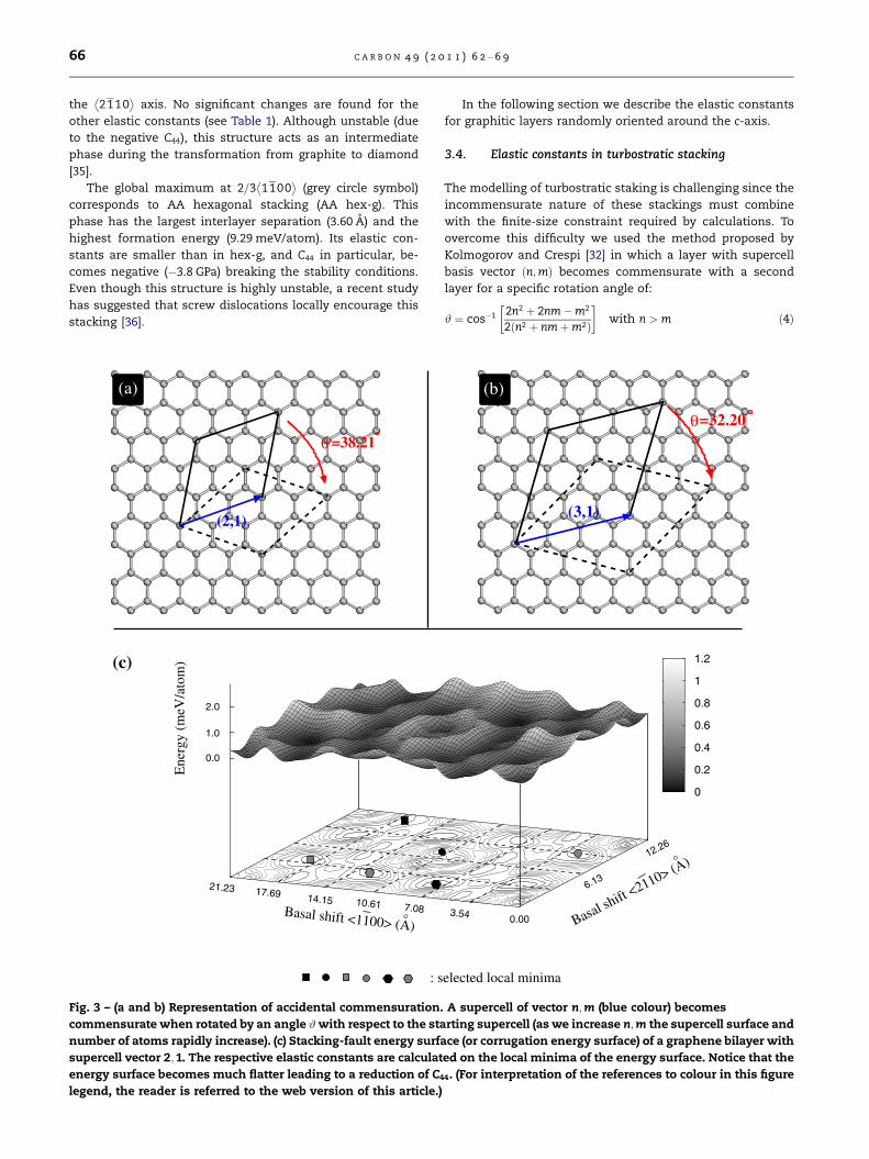
Fig. 3 – (a and b) Representation of accidental commensuration
commensurate when rotated by an angle #with respect to the sta
number of atoms rapidly increase). (c) Stacking-fault energy surf
supercell vector 2;1. The respective elastic constants are calculat
energy surface becomes much flatter leading to a reduction of C4
legend, the reader is referred to the web version of this article.)
In the following section we describe the elastic constants
for graphitic layers randomly oriented around the c-axis.
3.4. Elastic constants in turbostratic stacking
The modelling of turbostratic staking is challenging since the
incommensurate nature of these stackings must combine
with the finite-size constraint required by calculations. To
overcome this difficulty we used the method proposed by
Kolmogorov and Crespi [32] in which a layer with supercell
basis vector n;mð Þ becomes commensurate with a second
layer for a specific rotation angle of:
# ¼ cos�1 2n2 þ 2nm�m2
2 n2 þ nmþm2ð Þ
with n > m ð4Þ
0
0.2
0.4
0.6
0.8
1
1.2
elected local minima
3.54 0.00
6.13
12.26
Basal shift <
2110> (A)
=32.20
(3,1)
θ
(b)
. A supercell of vector n;m (blue colour) becomes
rting supercell (as we increase n;m the supercell surface and
ace (or corrugation energy surface) of a graphene bilayer with
ed on the local minima of the energy surface. Notice that the
4. (For interpretation of the references to colour in this figure
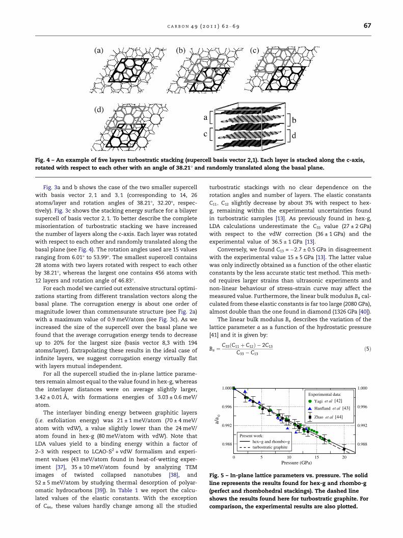
Fig. 4 – An example of five layers turbostratic stacking (supercell basis vector 2,1). Each layer is stacked along the c-axis,
rotated with respect to each other with an angle of 38.21� and randomly translated along the basal plane.
0 5 10 15 20
0.988 0.988
0.992 0.992
0.996 0.996
1.000 1.000
a/a
0
Pressure (GPa)
Yagi [27]
Hanfland [28]
Zhao [29]
hex−g and rhombo−gturbostratic graphite
Present work:
et al
et al
et al
Experimental data:
[44]
[43]
[42]
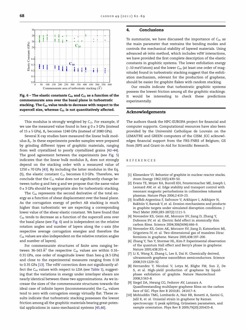
Fig. 5 – In-plane lattice parameters vs. pressure. The solid
line represents the results found for hex-g and rhombo-g
(perfect and rhombohedral stackings). The dashed line
shows the results found here for turbostratic graphite. For
comparison, the experimental results are also plotted.
C A R B O N 4 9 ( 2 0 1 1 ) 6 2 – 6 9 67
Fig. 3a and b shows the case of the two smaller supercell
with basis vector 2; 1 and 3;1 (corresponding to 14, 26
atoms/layer and rotation angles of 38.21�, 32.20�, respec-
tively). Fig. 3c shows the stacking energy surface for a bilayer
supercell of basis vector 2;1. To better describe the complete
misorientation of turbostratic stacking we have increased
the number of layers along the c-axis. Each layer was rotated
with respect to each other and randomly translated along the
basal plane (see Fig. 4). The rotation angles used are 15 values
ranging from 6.01� to 53.99�. The smallest supercell contains
28 atoms with two layers rotated with respect to each other
by 38.21�, whereas the largest one contains 456 atoms with
12 layers and rotation angle of 46.83�.For each model we carried out extensive structural optimi-
zations starting from different translation vectors along the
basal plane. The corrugation energy is about one order of
magnitude lower than commensurate structure (see Fig. 2a)
with a maximum value of 0.9 meV/atom (see Fig. 3c). As we
increased the size of the supercell over the basal plane we
found that the average corrugation energy tends to decrease
up to 20% for the largest size (basis vector 8,3 with 194
atoms/layer). Extrapolating these results in the ideal case of
infinite layers, we suggest corrugation energy virtually flat
with layers mutual independent.
For all the supercell studied the in-plane lattice parame-
ters remain almost equal to the value found in hex-g, whereas
the interlayer distances were on average slightly larger,
3.42 ± 0.01 A, with formations energies of 3.03 ± 0.6 meV/
atom.
The interlayer binding energy between graphitic layers
(i.e. exfoliation energy) was 21 ± 1 meV/atom (70 ± 4 meV/
atom with vdW), a value slightly lower than the 24 meV/
atom found in hex-g (80 meV/atom with vdW). Note that
LDA values yield to a binding energy within a factor of
2–3 with respect to LCAO-S2 + vdW formalism and experi-
ment values (43 meV/atom found in heat-of-wetting exper-
iment [37], 35 ± 10 meV/atom found by analyzing TEM
images of twisted collapsed nanotubes [38], and
52 ± 5 meV/atom by studying thermal desorption of polyar-
omatic hydrocarbons [39]). In Table 1 we report the calcu-
lated values of the elastic constants. With the exception
of C44, these values hardly change among all the studied
turbostratic stackings with no clear dependence on the
rotation angles and number of layers. The elastic constants
C11; C12 slightly decrease by about 3% with respect to hex-
g, remaining within the experimental uncertainties found
in turbostratic samples [13]. As previously found in hex-g,
LDA calculations underestimate the C33 value (27 ± 2 GPa)
with respect to the vdW correction (36 ± 1 GPa) and the
experimental value of 36.5 ± 1 GPa [13].
Conversely, we found C13 = �2.7 ± 0.5 GPa in disagreement
with the experimental value 15 ± 5 GPa [13]. The latter value
was only indirectly obtained as a function of the other elastic
constants by the less accurate static test method. This meth-
od requires larger strains than ultrasonic experiments and
non-linear behaviour of stress–strain curve may affect the
measured value. Furthermore, the linear bulk modulus Ba cal-
culated from these elastic constants is far too large (2080 GPa),
almost double than the one found in diamond (1326 GPa [40]).
The linear bulk modulus Ba describes the variation of the
lattice parameter a as a function of the hydrostatic pressure
[41] and it is given by:
Ba ¼C33ðC11 þ C12Þ � 2C13
C33 � C13ð5Þ
0 50 100 150 200 250 300 350 400 450 500 550 6000.0
0.1
0.2
0.3
0.4
24
26
28
30E
last
ic C
onst
ants
(G
Pa)
2Commensurate area of turbostratic stacking (A )
33
C44
C
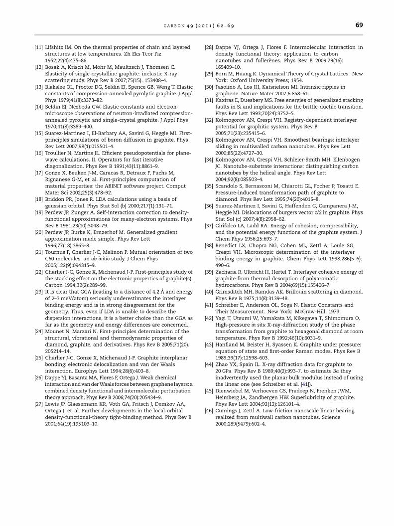
Fig. 6 – The elastic constants C44 and C33 as a function of the
commensurate area over the basal plane in turbostratic
stacking. The C44 value tends to decrease with respect to the
supercell size, whereas C33 is not quantitatively affected.
68 C A R B O N 4 9 ( 2 0 1 1 ) 6 2 – 6 9
This modulus is strongly weighted by C13. For example, if
we use the measured value found in hex-g 0 ± 3 GPa (instead
of 15 ± 5 GPa), Ba becomes 1240 GPa (instead of 2080 GPa).
Several X-ray studies have measured the linear bulk mod-
ulus Ba. In these experiments powder samples were prepared
by grinding different types of graphitic materials, ranging
from well crystallized to poorly crystallized grains [42–44].
The good agreement between the experiments (see Fig. 5)
indicates that the linear bulk modulus Ba does not strongly
depend on the stacking order with a measured value of
1250 ± 70 GPa [43]. By including the latter modulus in the Eq.
(5), the elastic constant C13 becomes 0.3 GPa. Therefore, we
conclude that the C13 value does not significantly change be-
tween turbo-g and hex-g and we propose that the same value
0 ± 3 GPa should be appropriate also for turbostratic stacking.
The C44 represents the second derivative of the total en-
ergy as a function of shear displacement over the basal plane.
As the corrugation energy of perfect AB stacking is much
higher than turbostratic we are expecting a corresponding
lower value of the shear elastic constant. We have found that
C44 tends to decrease as a function of the supercell area over
the basal plane (see Fig. 6) and is independent on the relative
rotation angles and number of layers along the c-axis (the
respective average corrugation energies and therefore the
C44 values are also independent on the relative rotation angles
and number of layers).
For commensurate structures of finite area ranging be-
tween 36–563 A2 the respective C44 values are within 0.16–
0.31 GPa, one order of magnitude lower than hex-g (4.5 GPa)
and close to the experimental measures ranging from 0.18
to 0.35 GPa [13]. The vdW correction does not significantly af-
fect the C44 values with respect to LDA (see Table 1), suggest-
ing that the variations in energy under interlayer shears are
nearly identical between these two approximations. As we in-
crease the sizes of the commensurate structures towards the
ideal case of infinite layers (incommensurate) the C44 values
tend to zero with corrugation energy virtually flat. These re-
sults indicate that turbostratic stacking possesses the lowest
friction among all the graphitic materials bearing great poten-
tial applications in nano-mechanical systems [45,46].
4. Conclusions
To summarize, we have discussed the importance of C44 as
the main parameter that restrains the bending modes and
controls the mechanical stability of layered materials. Using
advanced ab initio method, which includes vdW interactions,
we have provided the first complete description of the elastic
constants in graphitic systems. The lower exfoliation energy
(�10 meV/atom) and the lower C44 (at least one order of mag-
nitude) found in turbostratic stacking suggest that the exfoli-
ation mechanism, relevant for the production of graphene,
should be easier for graphite flakes with random stacking.
Our results indicate that turbostratic graphitic systems
possess the lowest friction among all the graphitic stackings.
It would be interesting to check these predictions
experimentally.
Acknowledgements
The authors thank the HPC-EUROPA project for financial and
computer supports. Computational resources have also been
provided by the Universite Catholique de Louvain on the
LEMAITRE and GREEN computers of the CISM. JCC acknowl-
edges financial support from the FRS-FNRS of Belgium; GS
from JSPS and Grant-in-Aid for Scientific Research.
R E F E R E N C E S
[1] Klimenkov VI. Behavior of graphite in nuclear reactor stacks.Atom Energy 1962;10(5):439–50.
[2] Evans TE, Moyer RA, Burrell KH, Fenstermacher ME, Joseph I,Leonard AW, et al. Edge stability and transport control withresonant magnetic perturbations in collisionless tokamakplasmas. Nature Phys 2006;2:419–23.
[3] Scaffidi-Argentina F, Safronov V, Arkhipov I, Arkhipov N,Bakhtin V, Barsuk V, et al. Erosion mechanisms and productsin graphite targets under simulated disruption conditions. JNucl Mater 2000;283–287(2):1111–5.
[4] Novoselov KS, Geim AK, Morozov SV, Jiang D, Zhang Y,Dubonos SV, et al. Electric field effect in atomically thincarbon films. Science 2004;306(5696):666–9.
[5] Novoselov KS, Geim AK, Morozov SV, Jiang D, Katsnelson MI,Grigorieva IV, et al. Two-dimensional gas of massless Diracfermions in graphene. Nature 2005;438:197–200.
[6] Zhang Y, Tan Y, Stormer HL, Kim P. Experimental observationof the quantum Hall effect and Berry’s phase in graphene.Nature 2005;438:201–4.
[7] Li X, Wang X, Zhang L, Lee S, Dai H. Chemically derived,ultrasmooth graphene nanoribbon semiconductors. Science2008;319:1229–32.
[8] Hernandez Y, Nicolosi V, Lotya M, Blighe FM, Sun Z, DeS, et al. High-yield production of graphene by liquid-phase exfoliation of graphite. Nature Nanotechnol2008;3:563–8.
[9] Siegel DA, Hwang CG, Fedorov AV, Lanzara A.Quasifreestanding multilayer graphene films on the carbonface of SiC. Phys Rev B 2010;81. 241417–4.
[10] Mohiuddin TMG, Lombardo A, Nair RR, Bonetti A, Savini G,Jalil R, et al. Uniaxial strain in graphene by Ramanspectroscopy: G peak splitting, Gruneisen parameters, andsample orientation. Phys Rev B 2009;79(20):205433–8.
C A R B O N 4 9 ( 2 0 1 1 ) 6 2 – 6 9 69
[11] Lifshitz IM. On the thermal properties of chain and layeredstructures at low temperatures. Zh Eks Teor Fiz1952;22(4):475–86.
[12] Bosak A, Krisch M, Mohr M, Maultzsch J, Thomsen C.Elasticity of single-crystalline graphite: inelastic X-rayscattering study. Phys Rev B 2007;75(15). 153408–4.
[13] Blakslee OL, Proctor DG, Seldin EJ, Spence GB, Weng T. Elasticconstants of compression-annealed pyrolytic graphite. J ApplPhys 1979;41(8):3373–82.
[14] Seldin EJ, Nezbeda CW. Elastic constants and electron-microscope observations of neutron-irradiated compression-annealed pyrolytic and single-crystal graphite. J Appl Phys1970;41(8):3389–400.
[15] Suarez-Martinez I, El-Barbary AA, Savini G, Heggie MI. First-principles simulations of boron diffusion in graphite. PhysRev Lett 2007;98(1):015501–4.
[16] Troullier N, Martins JL. Efficient pseudopotentials for plane-wave calculations. II. Operators for fast iterativediagonalization. Phys Rev B 1991;43(11):8861–9.
[17] Gonze X, Beuken J-M, Caracas R, Detraux F, Fuchs M,Rignanese G-M, et al. First-principles computation ofmaterial properties: the ABINIT software project. ComputMater Sci 2002;25(3):478–92.
[18] Briddon PR, Jones R. LDA calculations using a basis ofgaussian orbital. Phys Stat Sol (b) 2000;217(1):131–71.
[19] Perdew JP, Zunger A. Self-interaction correction to density-functional approximations for many-electron systems. PhysRev B 1981;23(10):5048–79.
[20] Perdew JP, Burke K, Ernzerhof M. Generalized gradientapproximation made simple. Phys Rev Lett1996;77(18):3865–8.
[21] Tournus F, Charlier J-C, Melinon P. Mutual orientation of twoC60 molecules: an ab initio study. J Chem Phys2005;122(9):094315–9.
[22] Charlier J-C, Gonze X, Michenaud J-P. First-principles study ofthe stacking effect on the electronic properties of graphite(s).Carbon 1994;32(2):289–99.
[23] It is clear that GGA (leading to a distance of 4.2 A and energyof 2–3 meV/atom) seriously underestimates the interlayerbinding energy and is in strong disagreement for thegeometry. Thus, even if LDA is unable to describe thedispersion interactions, it is a better choice than the GGA asfar as the geometry and energy differences are concerned.,
[24] Mounet N, Marzari N. First-principles determination of thestructural, vibrational and thermodynamic properties ofdiamond, graphite, and derivatives. Phys Rev B 2005;71(20).205214–14.
[25] Charlier J-C, Gonze X, Michenaud J-P. Graphite interplanarbonding: electronic delocalization and van der Waalsinteraction. Europhys Lett 1994;28(6):403–8.
[26] Dappe YJ, Basanta MA, Flores F, Ortega J. Weak chemicalinteraction andvander Waals forces between graphenelayers:acombined density functional and intermolecular perturbationtheory approach. Phys Rev B 2006;74(20):205434–9.
[27] Lewis JP, Glaesemann KR, Voth GA, Fritsch J, Demkov AA,Ortega J, et al. Further developments in the local-orbitaldensity-functional-theory tight-binding method. Phys Rev B2001;64(19):195103–10.
[28] Dappe YJ, Ortega J, Flores F. Intermolecular interaction indensity functional theory: application to carbonnanotubes and fullerenes. Phys Rev B 2009;79(16):165409–10.
[29] Born M, Huang K. Dynamical Theory of Crystal Lattices. NewYork: Oxford University Press; 1954.
[30] Fasolino A, Los JH, Katsnelson MI. Intrinsic ripples ingraphene. Nature Mater 2007;6:858–61.
[31] Kaxiras E, Duesbery MS. Free energies of generalized stackingfaults in Si and implications for the brittle-ductile transition.Phys Rev Lett 1993;70(24):3752–5.
[32] Kolmogorov AN, Crespi VH. Registry-dependent interlayerpotential for graphitic system. Phys Rev B2005;71(23):235415–6.
[33] Kolmogorov AN, Crespi VH. Smoothest bearings: interlayersliding in multiwalled carbon nanotubes. Phys Rev Lett2000;85(22):4727–30.
[34] Kolmogorov AN, Crespi VH, Schleier-Smith MH, EllenbogenJC. Nanotube-substrate interactions: distinguishing carbonnanotubes by the helical angle. Phys Rev Lett2004;92(8):085503–4.
[35] Scandolo S, Bernasconi M, Chiarotti GL, Focher P, Tosatti E.Pressure-induced transformation path of graphite todiamond. Phys Rev Lett 1995;74(20):4015–8.
[36] Suarez-Martinez I, Savini G, Haffenden G, Campanera J-M,Heggie MI. Dislocations of burgers vector c/2 in graphite. PhysStat Sol (c) 2007;4(8):2958–62.
[37] Girifalco LA, Ladd RA. Energy of cohesion, compressibility,and the potential energy functions of the graphite system. JChem Phys 1956;25:693–7.
[38] Benedict LX, Chopra NG, Cohen ML, Zettl A, Louie SG,Crespi VH. Microscopic determination of the interlayerbinding energy in graphite. Chem Phys Lett 1998;286(5–6):490–6.
[39] Zacharia R, Ulbricht H, Hertel T. Interlayer cohesive energy ofgraphite from thermal desorption of polyaromatichydrocarbons. Phys Rev B 2004;69(15):155406–7.
[40] Grimsditch MH, Ramdas AK. Brillouin scattering in diamond.Phys Rev B 1975;11(8):3139–48.
[41] Schreiber E, Anderson OL, Soga N. Elastic Constants andTheir Measurement. New York: McGraw-Hill; 1973.
[42] Yagi T, Utsumi W, Yamakata M, Kikegawa T, Shimomura O.High-pressure in situ X-ray-diffraction study of the phasetransformation from graphite to hexagonal diamond at roomtemperature. Phys Rev B 1992;46(10):6031–9.
[43] Hanfland M, Beister H, Syassen K. Graphite under pressure:equation of state and first-order Raman modes. Phys Rev B1989;39(17):12598–603.
[44] Zhao YX, Spain IL. X-ray diffraction data for graphite to20 GPa. Phys Rev B 1989;40(2):993–7. to estimate Ba theyinadvertently used the planar bulk modulus instead of usingthe linear one (see Schreiber et al. [41]).
[45] Dienwiebel M, Verhoeven GS, Pradeep N, Frenken JWM,Heimberg JA, Zandbergen HW. Superlubricity of graphite.Phys Rev Lett 2004;92(12):126101–4.
[46] Cumings J, Zettl A. Low-friction nanoscale linear bearingrealized from multiwall carbon nanotubes. Science2000;289(5479):602–4.