best practices come from you -...
TRANSCRIPT

© 2015 Cisco and/or its affiliates. All rights reserved.BRKDCT-2378 Cisco Public
Best Practices come from
YOU
2

© 2015 Cisco and/or its affiliates. All rights reserved.BRKDCT-2378 Cisco Public
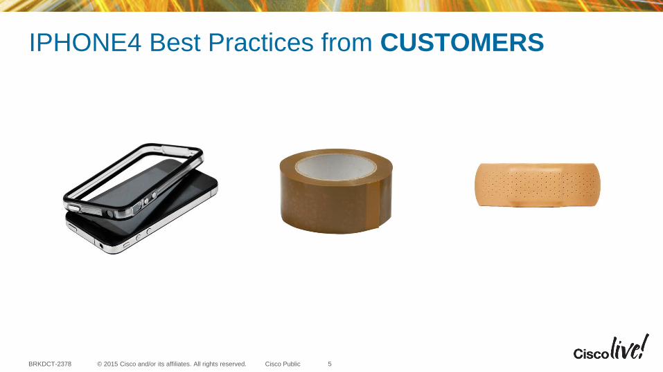
Apple iphone4 launched in June 2010
3

© 2015 Cisco and/or its affiliates. All rights reserved.BRKDCT-2378 Cisco Public
‘Antennagate’
4
© 2015 Cisco and/or its affiliates. All rights reserved.BRKDCT-2378 Cisco Public
IPHONE4 Best Practices from CUSTOMERS
5

vPC Best Practices and Design on NXOS
BRKDCT-2378
Nazim Khan, CCIE#39502 (DC/SP)
Technical Marketing Engineer, Data Center Group
© 2015 Cisco and/or its affiliates. All rights reserved.BRKDCT-2378 Cisco Public
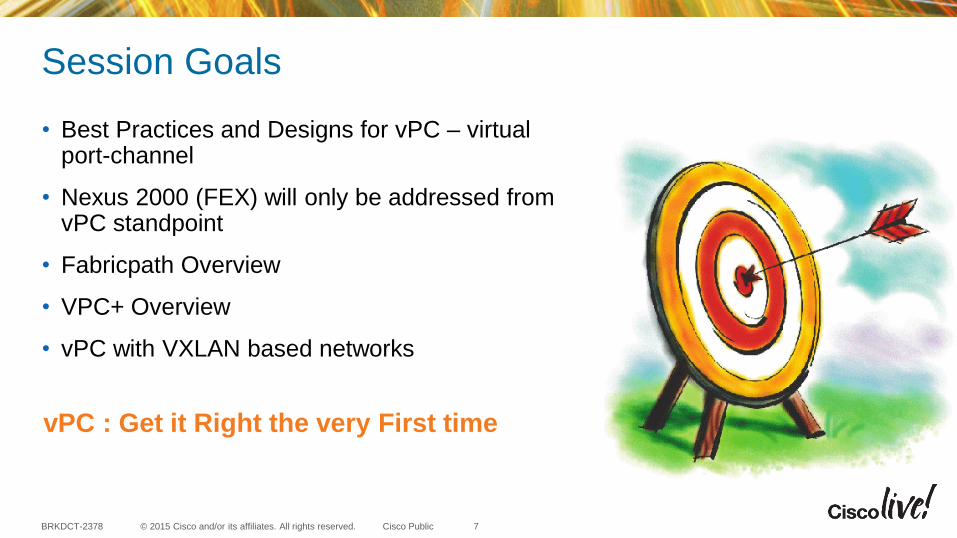
Session Goals
• Best Practices and Designs for vPC – virtual port-channel
• Nexus 2000 (FEX) will only be addressed from vPC standpoint
• Fabricpath Overview
• VPC+ Overview
• vPC with VXLAN based networks
7
vPC : Get it Right the very First time
© 2015 Cisco and/or its affiliates. All rights reserved.BRKDCT-2378 Cisco Public
Session Non-Goals
• vPC troubleshooting
• Details of vPC+
• Details of Fabricpath and VXLAN
• ACI with or without vPC
• FCoE
8
© 2015 Cisco and/or its affiliates. All rights reserved.BRKDCT-2378 Cisco Public
Agenda
• Feature Overview
• Configuration Best Practices
• Design Best Practices
• Fabricpath / vPC+
• VxLAN
• Scalability
• Reference Material
9

© 2015 Cisco and/or its affiliates. All rights reserved.BRKDCT-2378 Cisco Public
Data Center Technology Evolution
FabricPath with vPC+
2010
2009
VPC
2008
STP2013-2014
MPLS, OTV,
LISP
VXLAN
MPLS, OTV,
LISP
2014-2015
ACI
2010
FEX with vPC
10
© 2015 Cisco and/or its affiliates. All rights reserved.BRKDCT-2378 Cisco Public 11
Why vPC in 2015 ?

© 2015 Cisco and/or its affiliates. All rights reserved.BRKDCT-2378 Cisco Public
vPC is Foundation
12
© 2015 Cisco and/or its affiliates. All rights reserved.BRKDCT-2378 Cisco Public
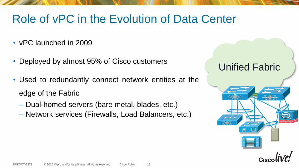
Role of vPC in the Evolution of Data Center
• vPC launched in 2009
• Deployed by almost 95% of Cisco customers
• Used to redundantly connect network entities at the
edge of the Fabric
– Dual-homed servers (bare metal, blades, etc.)
– Network services (Firewalls, Load Balancers, etc.)
Unified Fabric
13

© 2015 Cisco and/or its affiliates. All rights reserved.BRKDCT-2378 Cisco Public
Agenda
• Feature Overview− Concepts and Benefits− Terminology
• Configuration Best Practices
• Design Best Practices
• Fabricpath / vPC+
• VxLAN
• Scalability
• Reference Material
14

© 2015 Cisco and/or its affiliates. All rights reserved.BRKDCT-2378 Cisco Public
vPC Concept & Benefits
15
vPC Feature Overview
• No Blocked Ports, More Usable Bandwidth, Load Sharing
• Fast Convergence
STP vPC Physical Topology vPC Logical Topology
S3
S2S1
© 2015 Cisco and/or its affiliates. All rights reserved.BRKDCT-2378 Cisco Public
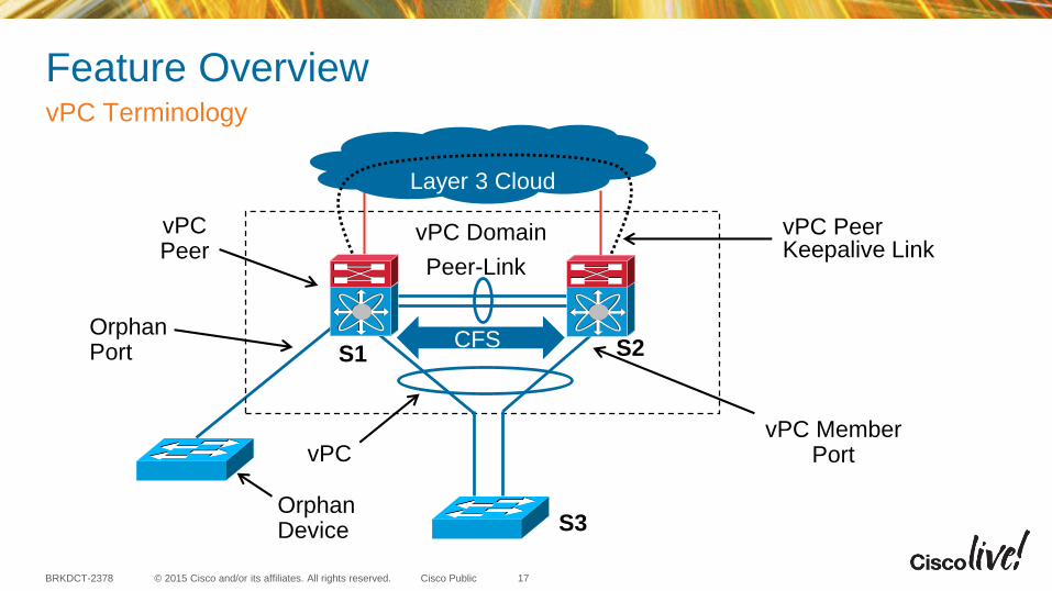
Feature OverviewvPC Terminology
17
Layer 3 Cloud
vPC Member PortvPC
Orphan Device
Orphan Port
vPCPeer
CFS
vPC Domain
Peer-Link
vPC PeerKeepalive Link
S1
S3
S2

© 2015 Cisco and/or its affiliates. All rights reserved.BRKDCT-2378 Cisco Public
SW3 SW4
vPC1 vPC2
vPC_PLink
vPC Peer-keepalive
vPC Peer-Keepalive Link up & vPC Peer-Link down
vPC Failure Scenario
Keepalive Heartbeat
Secondary vPC
P S
S
P Primary vPC
Suspend secondary
vPC Member Ports
vPC peer-link failure (link loss):
• VPC system checks active status of the remote vPC peer via peer-keepalive link (heartbeat)
• If both peers are active, then Secondary vPC peer will disable all vPCs to avoid Dual-Active
• Data will automatically forward down remaining active port channel ports
• Failover gated on CFS message failure, or UDLD/Link state detection
• Orphan devices connected to secondary peer will be isolated
© 2015 Cisco and/or its affiliates. All rights reserved.BRKDCT-2378 Cisco Public
Agenda•
• vPC Configuration Best Practices− Building a vPC domain− Domain-ID− Peer-Link− Peer-Keepalive Link− Spanning-Tree− Peer-switch− Auto-recovery− Object tracking− vPC shutdown− Maintenance Mode
•
•
•
•
•
19

© 2015 Cisco and/or its affiliates. All rights reserved.BRKDCT-2378 Cisco Public
Building a vPC domain – Configuration Steps
20
vPC Configuration Best Practices
CFS
1. Define domains
2. Establish Peer Keepalive connectivity
3. Create a Peer link
4. Create vPCs
5. Make Sure Configurations are Consistent
(Order does Matter!)
S1 S2
S3

© 2015 Cisco and/or its affiliates. All rights reserved.BRKDCT-2378 Cisco Public
vPC Configuration Best PracticesvPC Domain-ID
21
vPC Domain 10
vPC Domain 20
• The vPC peer devices use the vPC domain ID to
automatically assign a unique vPC system MAC
address
• You MUST use unique Domain id’s for all vPC
pairs defined in a contiguous layer 2 domain
! Configure the vPC Domain ID – It should be unique within the layer 2
domain
NX-1(config)# vpc domain 20
! Check the vPC system MAC address
NX-1# show vpc role
<snip>
vPC system-mac : 00:23:04:ee:be:14
S1 S2
S3 S4
S5

© 2015 Cisco and/or its affiliates. All rights reserved.BRKDCT-2378 Cisco Public
vPC Configuration Best PracticesvPC Peer-Link
22
• vPC Peer-link should be a point-to-point connection
• Peer-Link member ports can be 10/40/100GE interfaces
• Peer-Link bandwidth should be designed as per the vPC
• vPC imposes the rule that peer-link should never be blocking
S1 S1S2 S2
S3S3

© 2015 Cisco and/or its affiliates. All rights reserved.BRKDCT-2378 Cisco Public
vPC Configuration Best PracticesvPC Peer-Keepalive link
23
Preference Nexus 7X00 / 9X00
series
Nexus 6000 /
5X00 / 3X00
series
1 Dedicated link(s)
(1GE/10GE LC)
mgmt0 interface
2 mgmt0 interface Dedicated link(s)
(1GE/10GE LC)
3 L3 infrastructure L3 infrastructure
Recommendations
(in order of
preference):

© 2015 Cisco and/or its affiliates. All rights reserved.BRKDCT-2378 Cisco Public
vPC Configuration Best PracticesvPC Peer-Keepalive link – Dual Supervisors
24
Standby Management Interface
Active Management Interface
vPC1 vPC2
vPC_PL
Management Network
Management Switch
vPC_PKLvPC_PKL• When using dual supervisors and mgmt0 interfaces
to carry the vPC peer-keepalive, DO NOT connect
them back to back between the two switches
• Only one management port will be active a given point
in time and a supervisor switchover may break keep-
alive connectivity
• Use the management interface when you have an out-
of-band management network (management switch in
between)
For YourReference
© 2015 Cisco and/or its affiliates. All rights reserved.BRKDCT-2378 Cisco Public
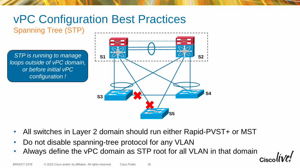
vPC Configuration Best PracticesSpanning Tree (STP)
25
• All switches in Layer 2 domain should run either Rapid-PVST+ or MST
• Do not disable spanning-tree protocol for any VLAN
• Always define the vPC domain as STP root for all VLAN in that domain
STP is running to manage
loops outside of vPC domain,
or before initial vPC
configuration !
S1 S2
S4S3
S5
© 2015 Cisco and/or its affiliates. All rights reserved.BRKDCT-2378 Cisco Public
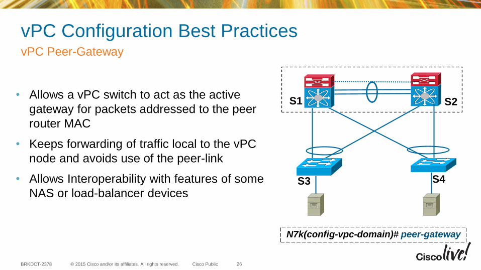
vPC Peer-Gateway
26
vPC Configuration Best Practices
• Allows a vPC switch to act as the active
gateway for packets addressed to the peer
router MAC
• Keeps forwarding of traffic local to the vPC
node and avoids use of the peer-link
• Allows Interoperability with features of some
NAS or load-balancer devices
N7k(config-vpc-domain)# peer-gateway
S1 S2
S4S3
© 2015 Cisco and/or its affiliates. All rights reserved.BRKDCT-2378 Cisco Public
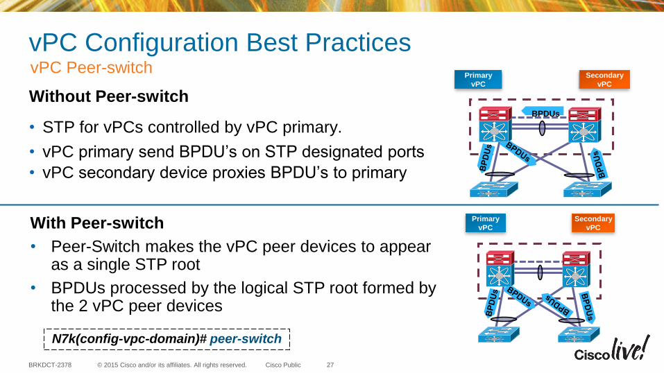
vPC Peer-switch
27
vPC Configuration Best PracticesPrimary
vPC
Secondary
vPC
BPDUs
Primary
vPC
Secondary
vPC
Without Peer-switch
• STP for vPCs controlled by vPC primary.
• vPC primary send BPDU’s on STP designated ports
• vPC secondary device proxies BPDU’s to primary
With Peer-switch
• Peer-Switch makes the vPC peer devices to appear as a single STP root
• BPDUs processed by the logical STP root formed by the 2 vPC peer devices
N7k(config-vpc-domain)# peer-switch

© 2015 Cisco and/or its affiliates. All rights reserved.BRKDCT-2378 Cisco Public
vPC auto-recovery
28
vPC Configuration Best Practices
1. vPC peer-link down : S2 - secondary shuts all its vPC member ports
2. S1 down : vPC peer-keepalive link down : S2 receives no keepalives
3. After 3 keepalive timeouts, S2 changes role and brings up its vPCvPC Primary
vPC Secondary
P
S
P
S2S1
S3
P S
Operational
Primary
S1 S2
S3
P S
S1 S2
S3
© 2015 Cisco and/or its affiliates. All rights reserved.BRKDCT-2378 Cisco Public
vPC auto-recovery
29
vPC Configuration Best Practices
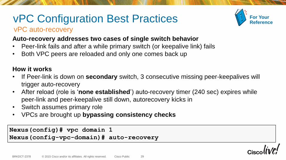
Auto-recovery addresses two cases of single switch behavior
• Peer-link fails and after a while primary switch (or keepalive link) fails
• Both VPC peers are reloaded and only one comes back up
How it works
• If Peer-link is down on secondary switch, 3 consecutive missing peer-keepalives will
trigger auto-recovery
• After reload (role is ‘none established’) auto-recovery timer (240 sec) expires while
peer-link and peer-keepalive still down, autorecovery kicks in
• Switch assumes primary role
• VPCs are brought up bypassing consistency checks
For YourReference
Nexus(config)# vpc domain 1
Nexus(config-vpc-domain)# auto-recovery

© 2015 Cisco and/or its affiliates. All rights reserved.BRKDCT-2378 Cisco Public
Why Object-Tracking ?
30
vPC Configuration Best Practices
Primary
S1 S2
Secondary
• Modules hosting peer-link and uplink
fail on the vPC primary
• Peer-Link is down and vPCSecondary shut all its vPC
• Auto-Recovery does not kick in as peer-keepalive link is active
• Traffic is black holedS3
S5S4

© 2015 Cisco and/or its affiliates. All rights reserved.BRKDCT-2378 Cisco Public
Object-tracking
31
vPC Configuration Best Practices
S1 S2
• Object Tracking triggered when the track object goes down
• vPC object tracking, tracks both peer-link and uplinks in a list of Boolean OR
• Traffic forwarded over the remaining vPC peer.
! Track the vpc peer link
track 1 interface port-channel11 line-protocol
! Track the uplinks
track 2 interface Ethernet1/1 line-protocol
track 3 interface Ethernet1/2 line-protocol
! Combine all tracked objects into one.
! “OR” means if ALL objects are down, this object will go down
track 10 list boolean OR
object 1
object 2
object 3
! If object 10 goes down on the primary vPC peer,
! system will switch over to other vPC peer and disable all local vPCs
vpc domain 1
track 10
• Suspends the vPCs on the impaired device.
S4 S5
S3

© 2015 Cisco and/or its affiliates. All rights reserved.BRKDCT-2378 Cisco Public
vPC Shutdown
32
vPC Configuration Best Practices
• Isolates a switch from the vPC complex
• Isolated switch can be debugged, reloaded, or
even removed physically, without affecting the
vPC traffic going through the non-isolated switch
Primary Secondary
vPC
This Feature is currently supported only on Nexus 5X00 and 600X series
S1 S2
S3
switch# configure terminal
switch(config)# vpc domain 100
switch(config-vpc)# shutdown

© 2015 Cisco and/or its affiliates. All rights reserved.BRKDCT-2378 Cisco Public
vPC Configuration Best Practices
1. vPC Primary enters maintenance mode via CLI
2. Running configuration is saved, key show command output is collected and saved
3. Change priority to highest value (65635)
4. Admin down all vPCs and vPC peer-link
5. Advertise state as “self-isolated” over peer keepalive link
vPC
Primary Secondary
1
2
4
5
3
Maintenance Mode
This Feature is currently supported only on Nexus 5X00 and 600X series

© 2015 Cisco and/or its affiliates. All rights reserved.BRKDCT-2378 Cisco Public
Agenda•
•
• vPC Design Best Practices
− Mixed Hardware across vPC Peers
− Dynamic Routing over VPC
− vPC and Multicast
− vPC as Data Center Interconnect (DCI)
− FHRP with vPC
− Hybrid topology (vPC and non-vPC)
− vPC and Network Services
− vPC Fex Supported Topologies
•
•
•
•
34

© 2015 Cisco and/or its affiliates. All rights reserved.BRKDCT-2378 Cisco Public
Mixed Hardware across vPC Peers : Line Cards
35
Design Best Practices
Always use identical line cards on either sides of the peer link and VPC legs !
vPC Peer-link
S1 S2
vPC Primary vPC Secondary
M2M1
vPC
vPC Peer-link
S1
N7000
S2
N7700
vPC Primary vPC Secondary
F3
vPC
F3
F2E F2E
Examples

© 2015 Cisco and/or its affiliates. All rights reserved.BRKDCT-2378 Cisco Public
Design Best PracticesMixed Hardware across vPC Peers : Chassis & Supervisors
vPC Peer-link
S1
N7000
S2
N7700
vPC Primary vPC Secondary
• N7000 and N7700 in same vPC Construct -Supported
• VDC type should match on both peer device
• vPC peers can have mixed SUP version* (SUP1, SUP2, SUP2E)
• N5X00 and N600X in same vPC Construct –Not Supported
*Recommended only for short period such as migration
36
vPC Peer-linkS1
N5X00
S2
N600X
vPC Primary vPC Secondary

© 2015 Cisco and/or its affiliates. All rights reserved.BRKDCT-2378 Cisco Public
BA
Router
Design Best Practices
37
• Don’t attach routers to VPC domain via L2 port-channel
• Common workarounds:
A. Individual L3 links for routed traffic
B. Static route to FHRP VIP
Router
L3 ECMP
Router
SVI 1
IP Y
VIP A
SVI 1
IP Z
VIP A
SVI 1
IP Y
VIP A
SVI 1
IP Z
VIP A
SVI 1
IP Y
VIP A
SVI 1
IP Z
VIP A
SVI 2
IP X
SVI 2
IP X
SVI 2
IP XStatic Route to VIP A
Dynamic Routing over VPC
S1 S1 S1 S2S2S2

© 2015 Cisco and/or its affiliates. All rights reserved.BRKDCT-2378 Cisco Public
vPC and Multicast
38
Design Best PracticesSource
ReceiversSource
• vPC supports PIM-SM only
• vPC uses CFS to sync IGMP state
• Sources in vPC domain− both vPC peers are forwarders
− Duplicates avoided via vPC loop-avoidance logic
• Sources in Layer 3 cloud− Active forwarder elected on unicast metric
− vPC Primary elected active forwarder in case metric are equal
S2S1
© 2015 Cisco and/or its affiliates. All rights reserved.BRKDCT-2378 Cisco Public
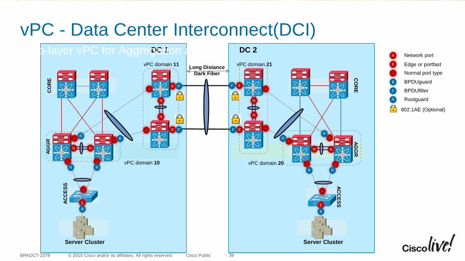
Long Distance
Dark Fiber
DC 1 DC 2C
OR
EA
GG
R
AC
CE
SS
Server Cluster
CO
RE
AG
GR
AC
CE
SS
Server Cluster
vPC domain 10 vPC domain 20
vPC domain 21vPC domain 11
vPC - Data Center Interconnect(DCI)Multi-layer vPC for Aggregation and DCI
39
Rootguard
B
F
N
E
BPDUguard
BPDUfilter
Network port
Edge or portfast
- Normal port type
R
802.1AE (Optional)
EE
- -
--
- -
E
E
E
E
F
F
F
F-
-
- -
-
--
B
N N
N
NN
N
R
R
-
RRRR
RR
NN
B
© 2015 Cisco and/or its affiliates. All rights reserved.BRKDCT-2378 Cisco Public
vPC as Data Center Interconnect (DCI)
40
Design Best Practices
PROS
• vPC is easy to configure and it provides robust and resilient interconnect solution
CONS
• Maximum of only two Data Centers can be interconnected
• Layer 3 peering between Data Centers cannot be done through vPC and separate links are required
© 2015 Cisco and/or its affiliates. All rights reserved.BRKDCT-2378 Cisco Public
Design Best PracticesvPC -Data Center Interconnect (DCI)
• vPC Domain id for vPC layers should be UNIQUE
• BPDU Filter on the edge devices to avoid BPDU propagation
• STP Edge Mode to provide fast Failover times
• No Loop must exist outside the vPC domain
• No L3 peering between Nexus 7000 devices (i.e. pure layer 2)
41

© 2015 Cisco and/or its affiliates. All rights reserved.BRKDCT-2378 Cisco Public
FHRP with vPCHSRP / VRRP/ GLBP Active/Active
• FHRP in Active/Active mode with vPC
• No requirement for aggressive FHRP timers
• Best Practice : Use default FHRP timers
42
L3
L2
FHRP
“Standby”:
Active for
shared L3 MAC
FHRP
“Active”:
Active for
shared L3 MAC
S1 S2

© 2015 Cisco and/or its affiliates. All rights reserved.BRKDCT-2378 Cisco Public
L3L2
OSPF/EIGRP
Primary
vPC
Secondary
vPC
OSPF/EIGRP
VLAN 99
FHRP with vPCBackup Routing Path• Point-to-point dynamic routing protocol
adjacency between the vPC peers to establish a L3 backup path to the core through PL in case of uplinks failure
• Define SVIs associated with FHRP as routing passive-interfaces in order to avoid routing adjacencies over vPC peer-link
• A single point-to-point VLAN/SVI (aka transit vlan) will suffice to establish a L3 neighbor
• Alternatively, use an L3 point-to-point link between the vPC peers to establish a L3 backup path
43
Routing Protocol PeerP
P
P
P
P
Use one transit vlan to establish L3 routing
backup path over the vPC peerlink in case L3
uplinks were to fail, all other SVIs can use
passive-interfaces
S2S1
S4S3
© 2015 Cisco and/or its affiliates. All rights reserved.BRKDCT-2378 Cisco Public
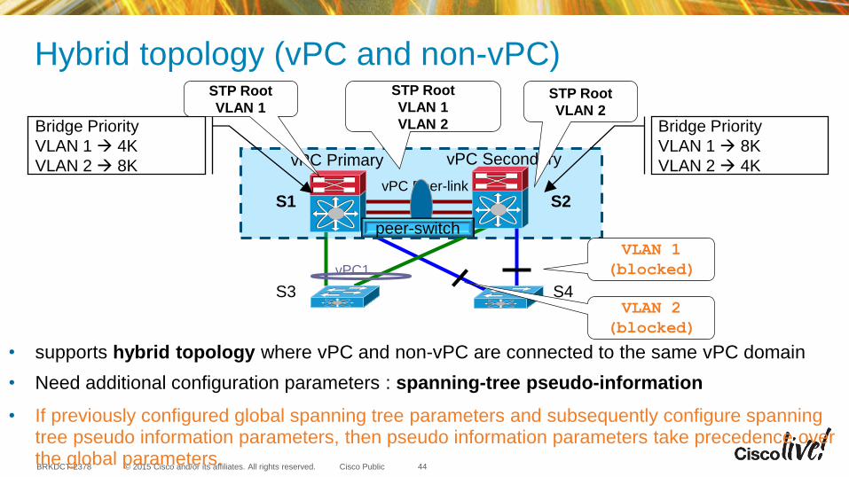
Hybrid topology (vPC and non-vPC)
vPC Peer-linkS1 S2
S3 S4
vPC Primary vPC Secondary
vPC1
Bridge Priority
VLAN 1 4K
VLAN 2 8K
Bridge Priority
VLAN 1 8K
VLAN 2 4K
STP Root
VLAN 1STP Root
VLAN 2
STP Root
VLAN 1
VLAN 2
VLAN 1
(blocked)
VLAN 2
(blocked)
• supports hybrid topology where vPC and non-vPC are connected to the same vPC domain
• Need additional configuration parameters : spanning-tree pseudo-information
• If previously configured global spanning tree parameters and subsequently configure spanning tree pseudo information parameters, then pseudo information parameters take precedence over the global parameters.
peer-switch
44

© 2015 Cisco and/or its affiliates. All rights reserved.BRKDCT-2378 Cisco Public
vPC and Network Services Services Chassis w. Services VDC Sandwich
46
Two Nexus 7000 Virtual Device Contexts to “sandwich” services between virtual switching layers
• Layer-2 switching in Services Chassis with transparent services
• vPC running in both VDC pairs to provide portchannel for both inside and outside interfaces to Services Chassis
Design considerations:
• Access switches requiring services are connected to sub-aggregation VDC
• Access switches not requiring services be connected to aggregation VDC
• If Peering at Layer 3 is required between vPC layers an alternative design should be explored (i.e. using STP rather than vPC to attach service chassis) or using static routing
Sub-Agg
Layer
Agg
Layer
Agg
Layer
Sub-Agg
Layer

© 2015 Cisco and/or its affiliates. All rights reserved.BRKDCT-2378 Cisco Public
Nexus 2000 (FEX) Straight-Through Deployment with VPC
• Port-channel connectivity from the server
• Two Nexus switches bundled into a vPCpair
• Suited for servers with Dual NIC and capable of running Port-Channel
Fex 100
Fabric Links
Fex 101
VPC
HIF HIF
48
S1 S2
* This design is currently not supported on N9500 series

© 2015 Cisco and/or its affiliates. All rights reserved.BRKDCT-2378 Cisco Public
Nexus 2000 (FEX)Active-Active Deployment with VPC
Nexus 6000 / 5000• Fabric Extender connected to two Nexus
5X00 / 6000
• Suited for servers with Single NIC or
Dual NIC not having port-channel
capability.
• Scale implications of less FEX per
system and less VPC
* This design is currently not supported on N7000 / N7700 and
N9X00
Fex 100 Fex
101HIF HIF
Fabric Links
Fabric Extender dual homed to
redundant Nexus switches
49
S1 S2
© 2015 Cisco and/or its affiliates. All rights reserved.BRKDCT-2378 Cisco Public
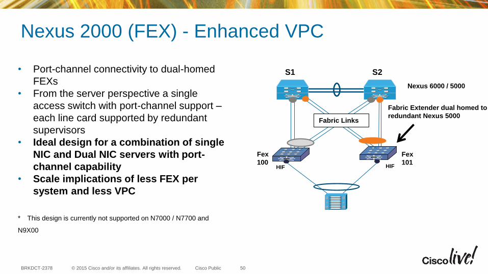
Nexus 2000 (FEX) - Enhanced VPC
• Port-channel connectivity to dual-homed
FEXs
• From the server perspective a single
access switch with port-channel support –
each line card supported by redundant
supervisors
• Ideal design for a combination of single
NIC and Dual NIC servers with port-
channel capability
• Scale implications of less FEX per
system and less VPC
* This design is currently not supported on N7000 / N7700 and
N9X00
Fex
100
Fex
101
Nexus 6000 / 5000
HIF HIF
Fabric Links
Fabric Extender dual homed to
redundant Nexus 5000
50
S2S1
© 2015 Cisco and/or its affiliates. All rights reserved.BRKDCT-2378 Cisco Public 51
vPC : Get it Right the very First time

© 2015 Cisco and/or its affiliates. All rights reserved.BRKDCT-2378 Cisco Public
Agenda
• Feature Overview
• vPC Configuration Best Practices
• vPC Design Best Practices
• Fabricpath / vPC+
• vPC in VxLAN network
• Scalability
• Reference Material
52

© 2015 Cisco and/or its affiliates. All rights reserved.BRKDCT-2378 Cisco Public
FabricPath: an Ethernet FabricShipping on Nexus 7x00, Nexus 600x and Nexus 5x00
53
N7K(config)# interface ethernet 1/1
N7K(config-if)# switchport mode fabricpath
• Eliminates Spanning tree limitations
• High resiliency, fast network re-convergence
• Any VLAN, Anywhere in the Fabric
• Connect a group of switches using an arbitrary topology
• With a simple CLI, aggregate them into a Fabric
FabricPath

© 2015 Cisco and/or its affiliates. All rights reserved.BRKDCT-2378 Cisco Public
• Physical architecture of vPC and vPC+ is the same from the access edge
• Functionality/Concepts of vPC and vPC+ are the same
• Key differences are addition of Virtual Switch ID and Peer Link is a FP Core Port
• vPC+ is not supported on Nexus 9X00 & Nexus 3X00 Series
Architecture of vPC and FabricPath with vPC+
VPC vs VPC+
FP Port
FP VLAN’s
vPC+
FP
CE Port
CE VLAN’s
vPC
CE
54
© 2015 Cisco and/or its affiliates. All rights reserved.BRKDCT-2378 Cisco Public
A
S10 S20 S30 S40
S100 S200S300
B
1/1
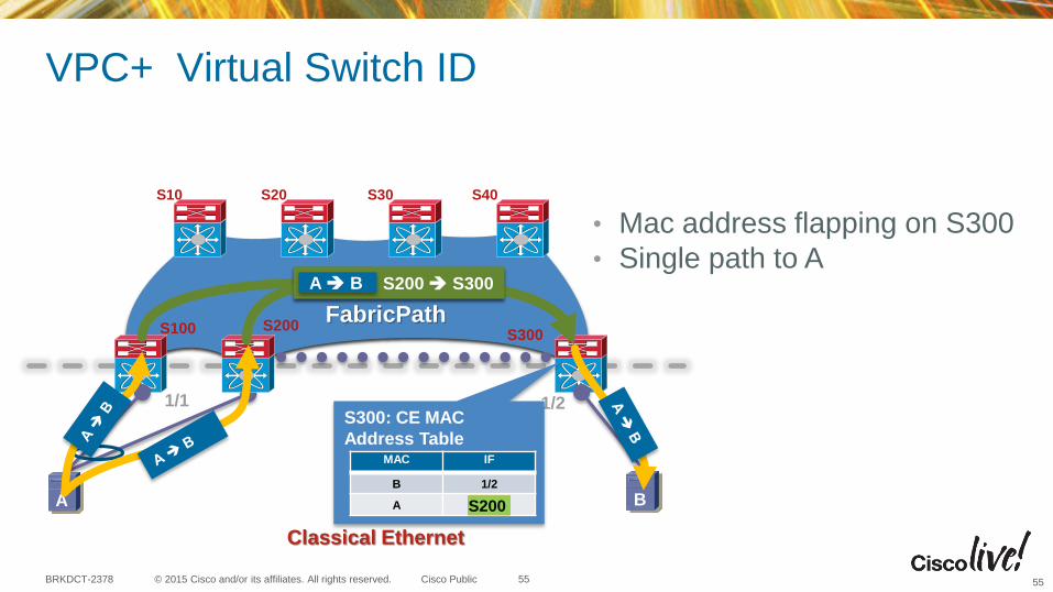
VPC+ Virtual Switch ID
Classical Ethernet
1/2
FabricPath
S300: CE MAC
Address TableMAC IF
B 1/2
A S100
S100 S300A B
S100
S200 S300A B
S200
• Mac address flapping on S300
• Single path to A
5555
© 2015 Cisco and/or its affiliates. All rights reserved.BRKDCT-2378 Cisco Public
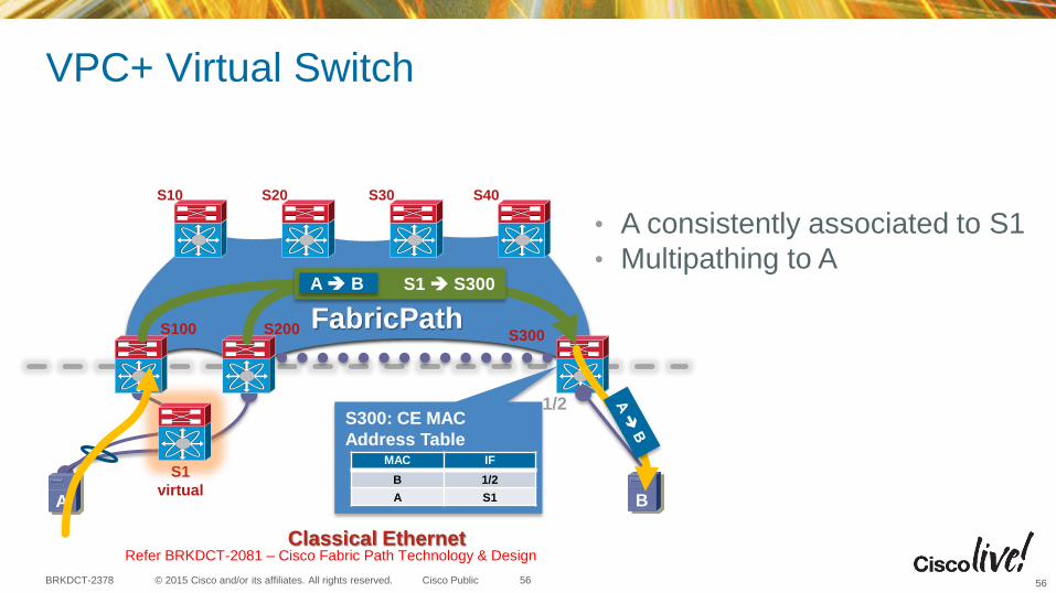
A
S10 S20 S30 S40
S100 S200 S300
B
VPC+ Virtual Switch
Classical Ethernet
1/2
FabricPath
S300: CE MAC
Address TableMAC IF
B 1/2
A S1
S1
virtual
S1 S300A B
• A consistently associated to S1
• Multipathing to A
56
Refer BRKDCT-2081 – Cisco Fabric Path Technology & Design
56

© 2015 Cisco and/or its affiliates. All rights reserved.BRKDCT-2378 Cisco Public 57
Dynamic Routing over vPC+
vPC
Fabricpath Core
P P
PP Routing Protocol Peer
N55xx, N56xx, N6000
Router/ Firewall
Dynamic Peering Relationship
• Layer 3 devices can form routing adjacencies with both the vPC+ peers over vPC
• The peer link ports and VLAN are configured in FabricPath mode.
• N55xx, N56xx, N6000 support this design with IPv4/IPv6 unicast and PIM-SM multicast
• This design is not supported on N7X00
Fabricpath Link

© 2015 Cisco and/or its affiliates. All rights reserved.BRKDCT-2378 Cisco Public
Agenda
• Feature Overview
• vPC Configuration Best Practices
• vPC Design Best Practices
• Fabricpath / vPC+
• VxLAN
• Scalability
• Reference Material
58

© 2015 Cisco and/or its affiliates. All rights reserved.BRKDCT-2378 Cisco Public 59
Problems being addressed:
• VLAN scale – VXLAN extends the L2 segment ID field to 24-bits, potentially allowing for up to 16 million unique L2 segments over the same network
• Layer 2 segment elasticity over Layer 3 boundary – VXLAN encapsulates L2 frame in IP-UDP header
High Level Technology Overview:
• MAC-in-UDP encapsulation.
• Leverages multicast in the transport network to simulate flooding behavior for broadcast, unknown unicast and multicast in the same segment
• Leverage ECMP to achieve optimal path usage over the transport network
Why VXLAN ?

© 2015 Cisco and/or its affiliates. All rights reserved.BRKDCT-2378 Cisco Public
VXLAN Packet Format
FCSOuter
Mac Header
Outer
IP HeaderUDP Header VXLAN
HeaderOriginal L2 Frame FCS
Dst.
MA
C A
ddr.
Src
.
MA
C A
ddr.
VLA
N T
ype
0x8100
VLA
N I
D
Ta
g
Eth
er
Type
0x0800
IP H
eader
Mis
cD
ata
Pro
tocol
0x11
Header
Checksum
Oute
r
Src
. IP
Oute
r
Dst.
IP
UD
P
Src
. P
ort
VX
LA
N P
ort
UD
P L
ength
Checksum
0x0000
VX
LA
N
RR
RR
1R
RR
Reserv
ed
VN
ID
Reserv
ed
14 Bytes
(4 bytes optional) 20 Bytes 8 Bytes 8 Bytes
48 48 16 16 16 72 8 16 32 32 16 16 16 16 8 24 24 8
• VXLAN is a Layer 2 overlay scheme over a Layer 3 network.
• VXLAN uses Ethernet in UDP encapsulation
• VXLAN uses a 24-bit VXLAN Segment ID (VNI) to identify Layer-2 segments
60
For YourReference

© 2015 Cisco and/or its affiliates. All rights reserved.BRKDCT-2378 Cisco Public
VTEP – Virtual Tunnel End Point
61
VXLAN Terminology
• VXLAN terminates its tunnels on VTEPs (Virtual Tunnel End Point).
• VTEP has two interfaces :
1. Bridging functionality for local hosts
2. IP identification in the core network for VXLAN encapsulation / de-encapsulation.
Local LAN Segment
IP Interface
End SystemEnd System
VTEP
Transport IP Network
Local LAN Segment
IP Interface
End SystemEnd System
VTEP
© 2015 Cisco and/or its affiliates. All rights reserved.BRKDCT-2378 Cisco Public
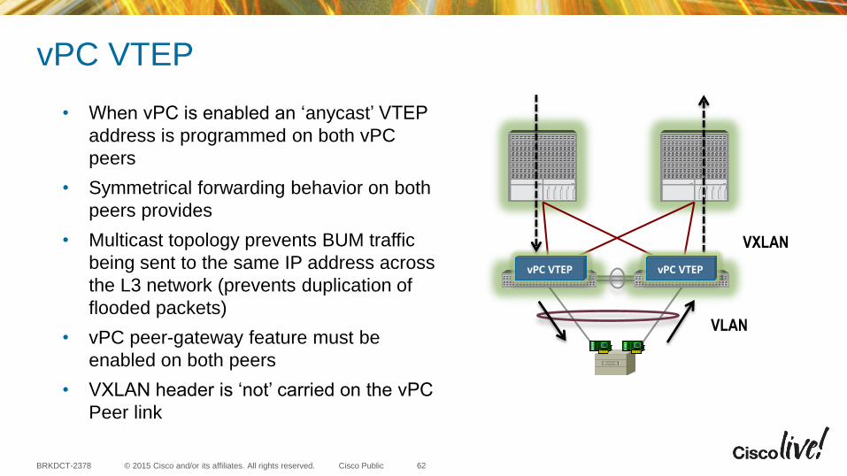
vPC VTEP
VXLAN
VLAN
vPC VTEP vPC VTEP
• When vPC is enabled an ‘anycast’ VTEP
address is programmed on both vPC
peers
• Symmetrical forwarding behavior on both
peers provides
• Multicast topology prevents BUM traffic
being sent to the same IP address across
the L3 network (prevents duplication of
flooded packets)
• vPC peer-gateway feature must be
enabled on both peers
• VXLAN header is ‘not’ carried on the vPC
Peer link
62
© 2015 Cisco and/or its affiliates. All rights reserved.BRKDCT-2378 Cisco Public
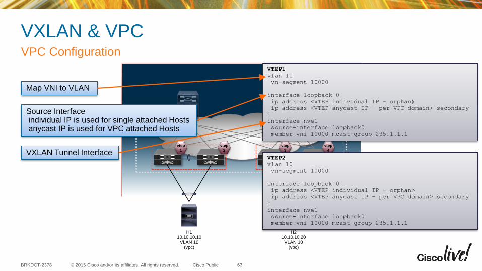
VXLAN & VPCVPC Configuration
63
vtep
1
vtep
2
vtep
3
vtep
4
H110.10.10.10
VLAN 10(vpc)
H210.10.10.20
VLAN 10(vpc)
VTEP1
vlan 10
vn-segment 10000
interface loopback 0
ip address <VTEP individual IP – orphan)
ip address <VTEP anycast IP – per VPC domain> secondary
!
interface nve1
source-interface loopback0
member vni 10000 mcast-group 235.1.1.1
Map VNI to VLAN
VXLAN Tunnel Interface
Source Interfaceindividual IP is used for single attached Hostsanycast IP is used for VPC attached Hosts
VTEP2
vlan 10
vn-segment 10000
interface loopback 0
ip address <VTEP individual IP - orphan>
ip address <VTEP anycast IP – per VPC domain> secondary
!
interface nve1
source-interface loopback0
member vni 10000 mcast-group 235.1.1.1

© 2015 Cisco and/or its affiliates. All rights reserved.BRKDCT-2378 Cisco Public
VXLAN & VPCVPC Configuration
64
vtep
1
vtep
2
vtep
3
vtep
4
H110.10.10.10
VLAN 10(vpc)
H210.10.10.20
VLAN 10(vpc)
VTEP1
vlan 10
vn-segment 10000
interface loopback 0
ip address 1.1.1.1/32
ip address 1.1.1.201/32 secondary
!
Interface nve1
source-interface loopback0
member vni 10000 mcast-group 235.1.1.1
VTEP3
vlan 10
vn-segment 10000
interface loopback 0
ip address 1.1.1.3/32
ip address 1.1.1.202/32 secondary
!
Interface nve1
source-interface loopback0
member vni 10000 mcast-group 235.1.1.1
VTEP2
vlan 10
vn-segment 10000
interface loopback 0
ip address 1.1.1.2/32
ip address 1.1.1.201/32 secondary
!
Interface nve1
source-interface loopback0
member vni 10000 mcast-group 235.1.1.1
VTEP4
vlan 10
vn-segment 10000
interface loopback 0
ip address 1.1.1.4/32
ip address 1.1.1.202/32 secondary
!
Interface nve1
source-interface loopback0
member vni 10000 mcast-group 235.1.1.1
For YourReference

© 2015 Cisco and/or its affiliates. All rights reserved.BRKDCT-2378 Cisco Public
VXLAN & VPCDual attached Host to dual attached Host (Layer-2)
65
vtep
1
vtep
2
vtep
3
vtep
4
H110.10.10.10
VLAN 10(vpc)
H210.10.10.20
VLAN 10(vpc)
• Host 1 (H1) and Host 2 (H2) are
dual connected to a VPC domain
• As H1 is behind a VPC interface, the
anycast VTEP IP is the source for
the the VXLAN encapsulation
• As H2 is behind a VPC interface, the
anycast VTEP IP is the target

© 2015 Cisco and/or its affiliates. All rights reserved.BRKDCT-2378 Cisco Public
Agenda
• Feature Overview
• vPC Configuration Best Practices
• vPC Design Best Practices
• Fabricpath / vPC+
• VxLAN
• Scalability
• Reference Material
66

© 2015 Cisco and/or its affiliates. All rights reserved.BRKDCT-2378 Cisco Public
vPC Scalability
67
For Latest Scalability numbers please refer to the scalability limits pages for the platform
Nexus 7X00
http://www.cisco.com/en/US/docs/switches/datacenter/sw/verified_scalability/b_Cisco_Nexus_7000_Series_NX-OS_Verified_Scalability_Guide.html
Nexus 5X00http://www.cisco.com/c/en/us/td/docs/switches/datacenter/nexus5600/sw/verified_scalability/701N11/b_N5600_Verified_Scalability_701N11/b_N6000_Verified_
Scalability_700N11_chapter_01.html
Nexus 600X http://www.cisco.com/c/en/us/td/docs/switches/datacenter/nexus6000/sw/verified_scalability/602N21/b_N6000_Verified_Scalability_602N21/b_N6000_Verified_
Scalability_602N12_chapter_01.html
Nexus 3000 http://www.cisco.com/en/US/docs/switches/datacenter/nexus3000/sw/configuration_limits/503_u5_1/b_Nexus3k_Verified_Scalability_503U51.html

© 2015 Cisco and/or its affiliates. All rights reserved.BRKDCT-2378 Cisco Public
Agenda
• Feature Overview
• vPC Configuration Best Practices
• vPC Design Best Practices
• Fabricpath / vPC+
• VxLAN
• Scalability
• Reference Material
68
© 2015 Cisco and/or its affiliates. All rights reserved.BRKDCT-2378 Cisco Public
Reference Material
69
• vPC Best Practices Design Guide: http://www.cisco.com/en/US/docs/switches/datacenter/sw/design/vPC_design/vPC_best_practices_design_guide.pdf
• vPC design guides:
http://www.cisco.com/en/US/partner/products/ps9670/products_implementation_design_guides_list.html
• vPC and VSS Interoperability white Paper:
http://www.cisco.com/en/US/prod/collateral/switches/ps5718/ps708/white_paper_c11_589890.html
• VXLAN Overview :
http://www.cisco.com/c/en/us/products/collateral/switches/nexus-9000-series-switches/white-paper-c11-729383.html
• Fabrcipath whitepaper :
http://www.cisco.com/c/en/us/products/collateral/switches/nexus-7000-series-switches/white_paper_c11-687554.html
For YourReference

© 2015 Cisco and/or its affiliates. All rights reserved.BRKDCT-2378 Cisco Public
vPC in 2015 vPC Benefits
Fabricpath VXLAN
vPC Design & Best Practices
Key Take-Aways
• No Blocked Ports
• High availability
• Fast Convergence
• Eliminates Spanning-Tree *
• High resiliency
• vPC+ for legacy switches,
servers, hosts
• L2 segment scalability
• VTEP redundancy with
vPC
Optimal vPC performance with
recommended deployment
techniques
VXLAN, ACI, Fabricpath
70
© 2015 Cisco and/or its affiliates. All rights reserved.BRKDCT-2378 Cisco Public
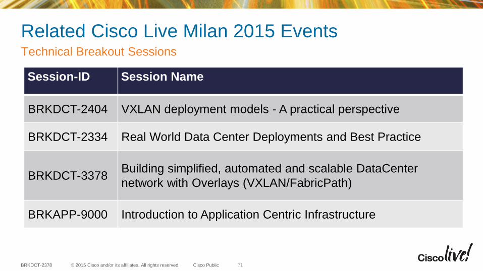
Related Cisco Live Milan 2015 EventsTechnical Breakout Sessions
71
Session-ID Session Name
BRKDCT-2404 VXLAN deployment models - A practical perspective
BRKDCT-2334 Real World Data Center Deployments and Best Practice
BRKDCT-3378Building simplified, automated and scalable DataCenter
network with Overlays (VXLAN/FabricPath)
BRKAPP-9000 Introduction to Application Centric Infrastructure
© 2015 Cisco and/or its affiliates. All rights reserved.BRKDCT-2378 Cisco Public
Call to Action
• Visit the World of Solutions for
– Cisco Campus – Data Center and Cloud
– Walk in Labs
– Technical Solution Clinics
• Meet the Engineer (Right after this session, until 30th Jan 2015)
• Lunch time Table Topics
• DevNet zone related labs and sessions
• Recommended Reading: for reading material and further resources for this session, please visit www.pearson-books.com/CLMilan2015
72

© 2015 Cisco and/or its affiliates. All rights reserved.BRKDCT-2378 Cisco Public
Complete Your Online Session Evaluation
• Please complete your online sessionevaluations after each session.Complete 4 session evaluations& the Overall Conference Evaluation(available from Thursday)to receive your Cisco Live T-shirt.
• All surveys can be completed viathe Cisco Live Mobile App or theCommunication Stations
73
