best practices-long life flexible pavement … · 0 pavementsjune 26, 2013 recommendations for the...
TRANSCRIPT

0
PAVEMENTS June 26, 2013
RECOMMENDATIONS FOR THE DESIGN AND CONSTRUCTION OF LONG LIFE FLEXIBLE PAVEMENT
ALTERNATIVES USING EXISTING PAVEMENTS
1
Table of Contents Topic Page
Introduction 3
HMA Renewal Strategies 4
General Guiding Principles 4
HMA Overlays over Existing HMA Pavements 5
Criteria for Long Life Potential 5
HMA over Existing HMA and Specifications 7
HMA over Reclaimed HMA Pavement 7
Criteria for Long Life Potential 7
Construction Operations 8
Quality Control 11
HMA over Reclaimed HMA Pavement and Specifications 11
HMA Overlays over Existing HMA-Surfaced Composite Pavements 12
HMA over Crack and Seat JPC Pavements 13
Criteria for Long Life Potential 13
HMA over Crack and Seat PCC and Specifications 15
HMA over Saw Crack and Seat JRC Pavements 16
Criteria for Long Life Potential 16
HMA over Saw, Crack, Seat PCC and Specifications 19
HMA over Rubblized Concrete Pavements 19
Criteria for Long Life Potential 19
Construction Operations 20
Rubblized Concrete Size Requirements 24
Suitability for Rubblization 25
HMA over Rubblized PCC Pavement and Specifications 27
HMA over CRC Pavements 27
Criteria for Long Life Potential 27
Surface Preparation/Repair and Overlay Depths 29
HMA over Existing CRC Pavement and Specifications 33
Added Lanes and Approaches for Adjacent Structures 33
Approaches to Undercrossings, Bridges, and Overcrossing Structures 34
Added Lanes or Widening 35
Widening Next to Rubblized PCC Pavement 35
Widening Next to Crack and Seated or Saw, Crack and Seated PCC Pavement
36
Structural Design Criteria to Achieve Long Life 37
Basic Approach 37
Endurance Limits 37
Pavement Design Software 37
Example Designs 39

2
Topic Page
HMA “Mill and Fill” Overlay over Existing HMA Pavement 39
HMA Overlay over Fractured PCC Pavement 40
Minimum HMA Thicknesses 40
HMA Mix Design Criteria to Achieve Long Life 41
Surface Course 42
Binder (Intermediate) Course 44
Base Course 45
HMA Stripping—Causes, Assessment, Solutions 46
Introduction and Background 46
California Study 49
Tests to Predict Moisture Sensitivity 50
Component and Compatibility Tests 50
Tests on Loose Mix 50
Tests on Compacted Mix 52
Solutions—Treatment Methods and Compaction 54
HMA Stripping--Recap 55
Project Evaluation 55
The Basics 55
Top-Down Cracking 58
HMA Construction Quality Control 61
HMA Density 61
HMA Segregation 62
Longitudinal Joints 64
Interlayer Bonding 65
QC Testing 65
HMA Quality Control and Specifications 65
Summary 67
References 69

3
RECOMMENDATIONS FOR THE DESIGN AND CONSTRUCTION OF LONG LIFE FLEXIBLE PAVEMENT ALTERNATIVES USING EXISTING
PAVEMENTS
Introduction
For purposes of this study, long life pavement is defined as pavement sections designed and built to last 50 years or longer without requiring major structural rehabilitation or reconstruction. Only periodic surface renewal in response to distresses confined to the top of the pavement would be required. This document was developed by the study team with input from State DOTs and HMA paving contractors.
The intent of the long life pavement concept is to significantly extend current pavement design life by restricting distress, such as cracking and rutting, to the pavement surface. Common distress mechanisms such as bottom-up fatigue cracking and rutting in the unbound layers should, in principle, be completely eliminated. However, surface initiated (top-down) cracking will still be possible. This type of cracking is caused by a complex combination of pavement structure, load spectra, environmental and material characteristics. While its causes are still not fully resolved, this deterioration mechanism involves a fatigue-like response in the upper layers of the pavement. In addition to fatigue cracking and rutting, in cold climates, low-temperature cracking and frost heave must also be taken into account. Another deterioration mechanism that should be accounted for is aging. Aging mainly affects the top asphalt layers and is manifested by increased stiffness and decreased flexibility over time. A common denominator of the distress mechanisms mentioned above is they are difficult to model using current mechanistic-empirical methods. In the case of top-down cracking and permanent deformations in the asphalt-bound layers, new and improved design methods may address this in the future.
When using existing pavements, the inhibition of reflective cracking is crucial. Reflective cracking is caused by repetitive shearing, e.g., when a new asphalt layer is laid upon an already cracked layer. With time, the crack will propagate through the new layer. This is true irrespective of the existing pavement type (i.e., distressed HMA or PCC), although experience shows that reflective cracking can be more predominant when the existing pavement is a PCC. Reflection cracking can occur in an HMA overlay over any joint or crack in the PCC pavement. The current state-of-the-art does not provide accurate methods to predict the occurrence and growth of the reflection crack. However, a number of approaches have been shown to minimize or eliminate these occurrences. These approaches are discussed in the following sections along with a discussion of

4
those features and construction processes that are considered critical to produce long life pavements.
HMA Renewal Strategies The most promising renewal strategies for long life using existing pavements are:
HMA over HMA renewal methods o HMA over existing HMA pavement o HMA over reclaimed HMA (recycling)
HMA over PCC renewal methods o HMA over existing HMA-surfaced composite pavements o HMA over crack and seated JPC pavements o HMA over saw, crack and seat JRC pavements o HMA over rubblized JPC pavements o HMA over existing CRC pavements
Each strategy will be described in this document.
General Guiding Principles The following are guiding principles for any renewal solution to achieve good performing long life pavements:
Keep the renewal solution as simple as possible, but not too simple so as to not address critical underlying problems.
The quality of construction is essential in achieving long life pavements.
Pavements are supposed to act as one layer; therefore the bond between layers should never be compromised, and a few thick layers are always better than multiple thin layers.
All joints are weaknesses; therefore they need to be treated as such.
Good, continuous, and sustainable drainage is essential to long life pavement; therefore no matter how thick the renewal solution is, it can fail if drainage is not provided.
Foundation uniformity is essential to reduce/eliminate stress concentrations, which can cause future cracking.
A solid foundation allows good compaction; unsupported edges can never be properly compacted.
Thermal movements of the existing pavement are the underlying cause for much reflective cracking; therefore they must be eliminated (by fracturing the existing pavement).

5
Good performing asphalt mixtures should have high binder content and low air voids (to have high durability), and smaller nominal size (to avoid segregation).
The following sections provide best practices (guidelines) for each rapid renewal strategy to achieve long life pavements based on relevant literature and agency information.
HMA Overlays over Existing HMA Pavements
Criteria for Long Life Potential
This renewal solution is viable as long as the following critical features are met:
The surface condition is good and the structural capacity of the existing AC pavement is adequate for a potential long life pavement.
There is no evidence of stripping in any of the existing HMA layers (determined through coring and/or GPR testing).
Proper repair and surface preparation is provided for the existing surface layer, and a good tack/bond coat is provided.
The existing drainage system is in good working condition, or adequate drainage is provided.
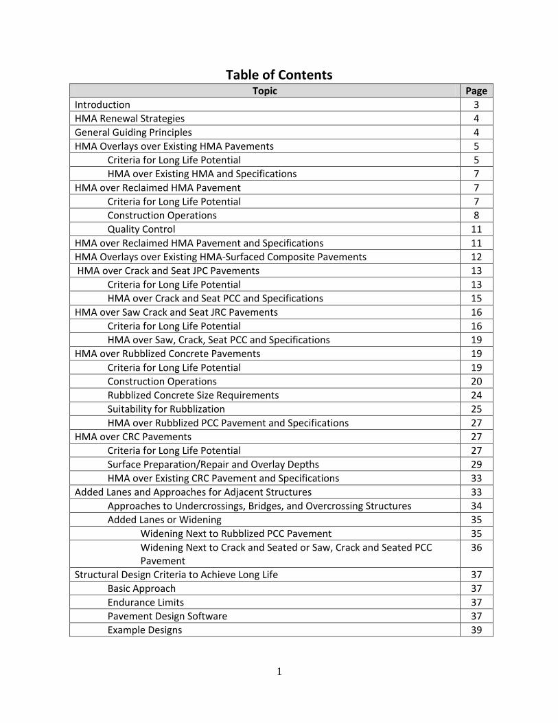
If there is no visible distress in the existing HMA pavement other than in isolated areas, the existing pavement can be directly overlaid as long as it is structurally sound, level, clean and capable of bonding to the overlay. Small areas of localized distresses in the existing pavement should be repaired or replaced to provide the required structural support. Milling before placing an overlay significantly aids the bond between the old and new HMA. When there is visible surface distress and it is determined that cracking is only present near the surface (through coring), the first step in the resurfacing process will be the removal of the existing surface to the depth of the cracking. This could vary between 1 and 4 in. of milled depth. The milled material would be replaced, and an additional thickness would be paved to ensure that limiting strain criteria are met. This layer would need to have the same characteristics as the original surface (i.e., rut resistance, durability, thermal cracking resistance, and wear resistance). Figure 1 shows a typical milling operation.
6
Figure 1. Typical milling operation of existing HMA layer. (WSDOT, 2010)
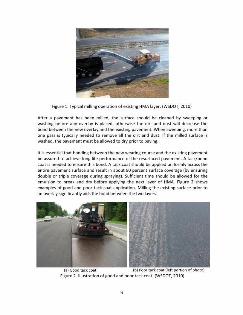
After a pavement has been milled, the surface should be cleaned by sweeping or washing before any overlay is placed, otherwise the dirt and dust will decrease the bond between the new overlay and the existing pavement. When sweeping, more than one pass is typically needed to remove all the dirt and dust. If the milled surface is washed, the pavement must be allowed to dry prior to paving. It is essential that bonding between the new wearing course and the existing pavement be assured to achieve long life performance of the resurfaced pavement. A tack/bond coat is needed to ensure this bond. A tack coat should be applied uniformly across the entire pavement surface and result in about 90 percent surface coverage (by ensuring double or triple coverage during spraying). Sufficient time should be allowed for the emulsion to break and dry before applying the next layer of HMA. Figure 2 shows examples of good and poor tack coat application. Milling the existing surface prior to an overlay significantly aids the bond between the two layers.
(a) Good tack coat
(b) Poor tack coat (left portion of photo)
Figure 2. Illustration of good and poor tack coat. (WSDOT, 2010)

7
Construction (longitudinal and transverse) joints should be minimized to the extent possible. Joints should be staggered between successive layers, to prevent a potential direct path for water, and sealed. Care should be taken to maximize the compaction (reduce the air voids) near joints, although it is difficult to achieve the same level of compaction as the main mat. The difference in air voids near joints should not be more than 2 percent relative to the density of the main mat. Further, no joints should be allowed within the area of the wheelpaths. Consideration should be given to sealing the longitudinal joints in addition to the emphasis on joint density. It is assumed that the existing pavement structure is competent enough to provide 50 years of service with the addition of sufficient overlay thickness. This condition will only be met by an existing pavement that is structurally sound and thick enough to satisfy limiting strain criteria. It is also assumed that this approach would be included in a project where additional lanes are constructed and the existing pavement is utilized to the extent possible.
The main limitation of this renewal solution is that reconstruction (i.e., removal of the existing pavement structure) is necessary if the condition of the existing base/subbase and/or subgrade is poor, or if the existing pavement is not structurally sound.
HMA over Existing HMA and Specifications A selection of significant practices associated with paving HMA over existing HMA were chosen and included in Table 1. The table includes a brief explanation why the issue is of special interest along with examples from the R23 guide specification recommendations. Three major practices are featured: (1) milling of existing HMA, (2) tack coat between HMA lifts, and (3) longitudinal and transverse joints.
HMA over Reclaimed HMA Pavement
Criteria for Long Life Potential
This renewal solution is necessary if the surface condition of the existing HMA layer is poor and the depth of the distress (cracking) is deeper in the pavement section. To enable use of the existing pavement, this solution entails the pulverization of the existing HMA layer. However, by definition, once this solution is adopted, the reclaimed HMA material is considered a base layer and its thickness should not be included in the total thickness that is used to calculate the limiting tensile strain at the bottom of the new HMA layer. Similar to using existing HMA pavement, the partial-depth and full-depth reclamation (FDR) renewal solution is viable only if the following critical features are met:

8
Proper surface preparation is provided for the reclaimed HMA layer, and a good tack/bond coat is provided between the reclaimed base and the new HMA overlay.
The foundation (subgrade) support is good (e.g., the backcalculated subgrade modulus is adequate for the planned section).
Drainage is adequately addressed. The main limitation of this renewal solution is that the performance of partial and full depth reclamation with cement or asphalt emulsion has not been substantiated for a long life (> 50 years); therefore their use in the context of long life pavements has not yet been fully proven in the field. Records on performance are highly variable as there has not been a common definition applied to judge the comparative performance levels. Causes commonly noted for poor performance using cold in-place recycling (CIPR) include (Hall et al, 2001): (1) use of an excessive amount of recycling agent, (2) application of a surface seal prematurely, (3) recycling only to the depth of an asphalt layer, resulting in de-lamination from the underlying layer, and/or (4) allowing a project to remain open for too long into the winter season. In addition, excessive processing can result in higher fines content, leading to rutting due to low stability.
Construction Operations In the FDR process, a reclaimer pulverizes the existing pavement and its base 4 to 10 in. deep and mixes in asphalt emulsion. Portland cement, lime and/or other materials can also be added as required to achieve desired mix quality, although the potential for shrinkage cracking that will reflect through the HMA layers is possible when dealing with cementitious materials. When only asphalt emulsion or foamed asphalt is used, it is directly blended within the reclaimer unit. When other cementing agents are added (e.g., dry lime, fly ash, or cement), they are spread with a vane spreader before blending. The mixed material is next compacted with a pad foot compactor, then bladed to level the surface. The level surface is then compacted with rubber tire rollers, followed by blade and steel face roller, without vibration, to shape. Finally, the new HMA base, wearing and surface courses are added to satisfy long life criteria. Figure 3 shows pictures of FDR construction with different stabilizing agents. Partial-depth reclamation by cold in-place recycling (CIPR) is limited to correcting only those distresses which are surface problems in the asphalt layer (Hall et al, 2001). Typically, this involves recycling of the asphalt bound layers to a depth of 3 to 4 in. The finished product is considered as a base only; therefore new HMA base, wearing and surface courses should be added to satisfy long life criteria.

9
Table 1. Summary of best practices and specifications for HMA over existing HMA
pavement. Best Practice Why this practice? Typical Specification Requirements
Milling of existing HMA
Existing cracks in the wearing course must be removed prior to HMA overlay to reduce potential for reflection cracks in the new HMA layer. Milling is considered superior to crack sealing prior to placing an HMA overlay and also aids the bond between the existing and new HMA.
Equipment must consistently remove the HMA surface, in one or more passes, to the required grade and cross section producing a uniformly textured surface. Machines must be equipped with all of the following:
Automatically controlled and activated cutting drums.
Grade reference and transverse slope control capabilities.
An approved grade referencing attachment, not less than 30 feet in length. An alternate grade referencing attachment may be used if approved by the Engineer prior to use.
[Refer to Elements for AASHTO
Specification 409 for more details]1
Tack coat between HMA lifts
It is essential that bonding between the new HMA layers courses and lower layers (such as the existing pavement) be achieved to ensure long life performance. If this is not done, then excessive tensile strains occur resulting in fatigue cracking. This is critical for the wearing course. Keep traffic off the fresh tack to the extent possible.
Apply the bond coat to each layer of HMA and to the vertical edge of the adjacent pavement before placing subsequent layers.
Apply a thin, uniform tack coat to all contact surfaces of curbs, structures, and all joints.
Apply undiluted tack at a rate ranging from 0.05 to 0.10 gal/SY.
Consider the use of a hot tack (traditional paving grade asphalt cement)—reduces wheel tracking and provides a consistent tack coat that is less susceptible to run-off during a rain event.
[Refer to Elements for AASHTO
Specification 404 for more details] 1
Longitudinal and transverse joints
There are two major issues: (1) achieve proper joint density, and (2) stagger the joints. If the joint density is low, then high air voids are the result—a typical restriction is no more than 2% higher voids in the joint than the middle of the HMA mat. If this type of criterion is violated, this leads to early joint raveling and cracking. Staggering the joints helps to prevent a direct path for water entering the pavement structure. Consider sealing longitudinal joints
Stagger joints according to AASHTO Guide Specification 401. An exception to the use of staggered joints can be made for achieving crown lines.
The minimum density of all traveled way pavement within 6 inches of a longitudinal joint, including the pavement on the traveled way side of the shoulder joint, shall not be less than 2.0 percent below the specified density when unconfined.
[Refer to Elements for AASHTO
Specification 401 for more details] 1
1 Contained in Appendix E-4

10
(a) FDR with asphalt emulsion
(b) FDR with cement/fly ash stabilizer
(c) FDR with asphalt emulsion and dry lime
(d) FDR with foamed asphalt
Figure 3. FDR construction with different stabilizing agents. (Bang et al, 2010)
CIPR is accomplished by a self-contained, continuous train operation that uses a milling machine to remove the existing surface layers to a given depth (up to about 4 in.). The material is sized with the oversized material crushed and re-screened. The material is then mixed in a pug mill, with asphalt cement or special asphalt-derived products (cationic, anionic, and polymer modified emulsions or foamed asphalt, rejuvenators and recycling agents developed especially for CIPR processes). Virgin aggregate might be added to complete the mix. The resulting mix is then laid using a reclaim/paver unit. After about 30 minutes of curing and drying, the material is compacted with a large rubber-tired roller, followed by a vibratory steel drum roller. Curing of about two weeks during favorable weather conditions (preferably at temperatures at or in excess of 60°F) is needed before the new HMA overlay is applied (FHWA, 1997). The addition of quick lime has been used to significantly reduce the cure time. Figure 4 shows typical CIPR train operations.

11
(a) CIPR Train with engineered asphalt emulsion
(b) CIPR Train with addition of lime slurry or cement in slurry
Figure 4. Typical CIPR train operation. (Hot-Mix Magazine, 2010)
Quality Control
The crucial initial step in the quality control of CIPR mixes is in the pavement type selection process. Pavements with rutting, heavy patching, or chip seals are not good candidates for CIPR projects. Core specimens should be taken from the existing HMA and examined for variations in pavement layers including delaminations and evidence of saturated material. The quality control of the RAP material itself is essential to ensure the success of a CIPR mix. This should involve taking random samples of the recycled material to analyze for aggregate gradation, asphalt content, and moisture content. Care should be taken to ensure that the RAP is consistent in size and appearance and is free of contaminants. Field quality control measures during CIPR operations should include monitoring the depth of scarification, the coating of the aggregate by the emulsion, the proper curing of the emulsion, the visual appearance and possible segregation of the recycled material, the compaction procedure, and appearance of the recycled pavement surface after compaction. The recycled mix should be monitored for gradation, emulsion content, moisture content and in-place density. Compaction of CIPR paving mixtures is normally accomplished at a moisture content of less than 2 percent at a minimum of 97 percent of laboratory maximum density (FHWA, 1997). Two recent reports illustrate the mix design and quality control measures applied to projects in Maryland and Colorado (Schwartz et al, 2013 and Cross, 2012).
HMA over Reclaimed HMA Pavement and Specifications A significant practice associated with the gradation of the pulverized material was selected and included in Table 2. The table includes a brief explanation why the issue is
12
of special interest along with examples from the study guide specification recommendations. One major practice is featured which is the gradation of the pulverized material.
Table 2. Best practices and specifications for HMA over reclaimed HMA pavement.
Best Practice
Why this practice? Typical Specification Requirement
Gradation of pulverized material
The existing pavement to be remixed with binder must have a gradation, and specifically the maximum particle size, small enough that the mixing process achieves well-coated particles.
The gradation of the pulverized material must achieve 100% passing the 2 in. sieve and 90 to 100% passing the 1.5 in. sieve.
Reject subgrade materials that can contaminate the pulverized asphalt pavement.
[Refer to Elements for AASHTO Specification 4111 and the AASHTO Guide Specification 411]
1 Contained in Appendix E-4
HMA Overlays over Existing HMA-Surfaced Composite Pavements A viable long life HMA renewal solution for HMA over concrete pavement is to mill the old HMA overlay and consider the HMA over PCC renewal methods described below (crack and seat JPC pavements, saw-cut crack and seat JRC pavements, or rubblize PCC pavement). Figure 5 shows a photo of an exposed concrete pavement after removal of the HMA overlay.

13
Figure 5. Existing concrete pavement exposed after removal of HMA layer. (Sebesta and Scullion, 2007)
HMA over Crack and Seat JPC Pavements
Criteria for Long Life Potential
This renewal solution is only suitable for plain (unreinforced) concrete pavements. The rationale behind the crack and seat technique is to shorten the effective slab length between the transverse joints or cracks in the existing concrete pavement before placing the HMA overlay. This will distribute the horizontal strains resulting from thermal movements of the concrete more evenly over the existing pavement, thus reducing the risk of causing reflective transverse cracks in the overlay. Care must be taken during cracking operations such that the induced concrete cracks are kept vertical and fine (tight). Generally, the cracking of the PCC slabs are in the transverse direction; however, the addition of longitudinal cracking between wheelpaths has shown good performance by Caltrans. Verification coring should follow to ensure that fine, full-depth vertical cracks are achieved (see Figure 6). The HMA overlay over crack and seat concrete renewal solution is viable as long as the following critical features are met:
There is no evidence of pumping underneath the existing slabs.
The foundation support is good (i.e., there are no voids between the concrete slab and the underlying base/subbase).
The existing drainage system is in good working condition.

14
However, the following limitations and additional cautions are warranted:
The performance of HMA overlays on crack and seat concrete pavements has been variable in the US; therefore it is unclear whether their efficacy is 50 years or longer. This could be tied to the quality of the cracking operation. If construction guidelines are put in-place to ensure the realization of closely spaced, tight, full-depth vertical cracks, then potential for long life should be achievable. Experience in the United Kingdom has been excellent, but with strict quality control process and HMA overlay thickness in excess of 7 in. Thinner overlays like those commonly used in the US were not found to work as well in test sections in the United Kingdom (Coley and Carswell, 2006). The need for informed inspectors on the job site during cracking operations cannot be overemphasized.
If the foundation underneath the existing concrete is not sufficiently strong, the crack and seat operation may cause excessive structural damage to the existing pavement.
(a) Example showing excessive longitudinal
cracking
(b) Example showing good transverse cracking
(c) Non-compliant core: Over-cracked
(d) Compliant core: Fine, full-depth vertical
crack

15
(e) Compliant crack illustrated by core hole
(f) Compliant crack illustrated by reassembled core
Figure 6. Examples of poor and good practices of crack and seat. (Jordan et al. 2008 (a)-(d); WSDOT 2011)
Caltrans (2004) has extensive experience with crack and seating of PCC slabs followed by an HMA overlay. The agency applies this treatment wherever the PCC pavement has an unacceptable ride and extensive slab cracking. The typical crack spacing is about 4 ft. by 6 ft. followed by seating with five passes of a pneumatic-tired roller of at least 15 tons (Caltrans, 2008). For a number of years (1980s through 1990s), the overlay thickness associated with the crack and seat process ranged from a minimum of 4 in. up to about 6 in. Service life expectation was a minimum of 10 years with these thicknesses (or about 10 to 20 million ESALs). Starting in 2003 with the Interstate 710 rehabilitation of existing 8 in. thick PCC slabs near Long Beach, CA (Monismith et al, 2009a and 2009b), the crack and seat process is followed by HMA overlays totaling 9 in. thick. The design ESAL levels for these sections of I-710 have ranged between 200 to 300 million. This renewable strategy adopted by Caltrans implies a long life of at least 40 years. A report by Rahim and Fiegel (2011) overviews the latest examination of CSOL performance in California. The information generally shows very limited longitudinal, transverse, and alligator cracking for a range of pavement sections located in various climate regions in the state. No attempt was made to determine if the origin of the cracking was bottom up or top down. A reasonable conclusion is the recent California data does not suggest any major issues for CSOL even with HMA overlay thicknesses of about 4.0 to 6.0 in.
HMA over Crack and Seat PCC and Specifications A significant practice associated with cracking operations which precede paving HMA over crack and seated PCC pavement was selected and included in Table 3. The table includes a brief explanation why the issue is of special interest along with examples from the study guide specification recommendations.

16
HMA over Saw Crack and Seat JRC Pavements
Criteria for Long Life Potential
It has been established that the crack and seat technique of fracturing reinforced concrete pavements (JRCP) has not been successful because of the inability to break the bond between the reinforcing steel and concrete nor to shear the steel along the plane of the crack. The bonded reinforcing steel results in thermal contraction concentrated at the existing transverse joints, thus leading to reflective cracks through the new HMA layer. Table 3. Best practices and specifications for HMA over crack and seated PCC pavement.
Best Practice
Why this practice? Typical Specification Requirement
Cracking Operations
The crack and seat technique is to shorten the effective slab length between the transverse joints or cracks in the existing concrete pavement before placing the HMA overlay. This distributes the horizontal strains resulting from thermal movements of the existing PCC more evenly, thus reducing the risk of causing reflective cracks in the AC overlay.
AASHTO 567 recommends a cracking pattern that results in PCC pieces of 1.2 to 1.8 ft
2 in area. Other state
experience, such as Caltrans, suggests that a larger cracking pattern can work well for JPCP such as 6 ft by 5 ft (for a 12 ft wide lane with 15 ft contraction joint spacing, this results in a lane cracked in half and approximately at the third points).
The study team recommends the minimum distance from a contraction joint to initiate cracking be 3 ft. This should ensure that the cracked areas be dimensioned with a 2 to 1 ratio or less. This assumes the slab is longitudinally cracked down the middle.
Produce cracks that are continuous without extensive spalling along the crack. Verify that the cracking extends fully through the slab by use of cores (not an AASHTO guide specification requirement).
[Refer to Elements for AASHTO Specification 567
1 and AASHTO Guide
Specification 567 for more details] 1 Contained in Appendix E-4 An alternative solution is to saw narrow transverse cuts into the concrete deep enough to cut through the longitudinal steel reinforcement, then crack the pavement at the locations of the sawed cuts using the same crack and seat procedure described above (Merrill, 2005), see Figure 7. The same precautions as noted for crack and seat construction apply. The depth of the cut can be determined from coring and/or ground-

17
penetrating radar (GPR) testing. The use of a strike plate is recommended to prevent spalling during the cracking operations. Verification coring should follow to ensure that fine, full-depth vertical cracks are achieved (see Figure 8). The spacing of saw-cuts should be similar to the cracking pattern used in the crack and seat procedures. The UK Department of Transport Road Note 41 (Jordan et al, 2008) recommends a spacing of 3 to 6 ft. Under these conditions, the critical features and limitations are the same as for the crack and seat approach.
Figure 7. Sawing of concrete slabs. (Jordan et al. 2008) Because cracks are not visible in this process, more extensive coring is required to confirm that the pavement has been cracked. The Department of Transport (UK, 2010) also requires cores to verify that the steel reinforcing has been cut and the slab is fully cracked. In addition, they require FWD deflection testing and backcalculation to verify a minimum modulus (termed effective stiffness modulus) of the PCC layer following cutting, cracking and seating. Following cutting and cracking, the Department of Transport (UK, 2010) requires seating the PCC with a pneumatic roller with a total weight ≥ 20 tonnes. Similar to crack and seating, thicker overlays were found to perform much better than thinner overlays in test sections in the United Kingdom (Coley and Carswell, 2006).

18
(a) Non-compliant core: Steel
reinforcement not severed
(b) Compliant core: Fine, full-depth,
vertical crack
(c) Spalling of saw-cut because of no strike
plate use
(d) Strike plate in use
Figure 8. Examples of poor and good practices of sawcut, crack and seat.
(Jordan et al. 2008)
19
HMA over Saw, Crack, Seat PCC and Specifications A significant practice regarding precutting existing reinforcing steel before paving HMA over saw, crack, and seat PCC was selected and included in Table 4. The table includes a brief explanation why sawing the existing reinforcing steel is of special interest along with examples from the study guide specification recommendations.
Table 4. Best practices and specifications for HMA over saw, crack and seat jointed
reinforced PCC.
Best Practice
Why this practice? Typical Specification Requirement
Depth of saw cut
The reinforcing steel in JRP must be fully severed so that the bond between the PCC and the steel is released. This significantly reduces the thermal stresses at the preexisting joints to be reduced to manageable levels. This saw cutting precedes the crack and seat operation.
1. Preparatory work: Prior to sawing, the following work must be complete: a. If required, construct pavement drainage systems at least two weeks prior to saw cutting and cracking and seating. b. Any existing material overlaying the concrete pavement must be removed.
2. Sawing: Transverse saw cuts will be made at a 4 to 5 ft. spacing along the centerline of the pavement to the depth required to cut the reinforcing steel found in the jointed reinforced concrete pavement.
3. Cracking and seating: Cracking and seating shall proceed in accordance with the guide specifications for Cracking and Seating with the additional requirement that the equipment used to crack the pavement will include a protective plate that eliminates any spalling of the saw cut during the cracking operation.
[Refer to R23 Guide Specifications for Saw, Crack and Seat Elements1 for more details]
1 Contained in Appendix E-4
HMA over Rubblized Concrete Pavements
Criteria for Long Life Potential
In principle, rubblization effectively eliminates the problem of reflection cracking, since the technique is supposed to completely disintegrate the existing concrete slab. However, it also reduces the strength of the existing concrete pavement substantially since it renders the concrete into broken fragments resembling an unbound base course, although with “aggregate” sizes much larger than a regular crushed aggregate

20
base layer. Thus, it is the only approach that utilizes the existing concrete pavement and fully addresses slab movement responsible for reflective cracking; although, crack and seat processing is generally preferred to rubblization since the former keeps more of the existing PCC slab material intact.
This renewal solution is viable as long as the following critical features are met:
There is no evidence of pumping underneath the existing slabs.
The foundation support is good (i.e., there are no voids between the concrete slab and the underlying base/subbase).
The subgrade strength is acceptable.
The existing drainage system is in good working condition, or provisions can be made for installing a drainage system before rubblizing the concrete pavement.
However, the following limitations and additional cautions are warranted:
The performance of this solution is tied to the quality of the rubblization operation. If construction guidelines are put in-place to ensure that: (1) concrete below the reinforcement is broken, (2) the size distribution of the rubblized concrete pieces is as uniform as possible, although this will vary with depth, (3) the maximum size of the rubblized concrete pieces in the bottom half is kept within the specification limits, and (4) the steel reinforcement—where present—is debonded from the concrete, then long life may be achievable.
If the foundation underneath the existing concrete is not sufficiently strong, the rubblization operation may damage the base/subbase and/or the existing subgrade and produce an unstable base layer.
Moisture problems, soft spots, and voids underneath the slab should be addressed prior to rubblization for enhanced performance.
It is noted that the rubblization process leads to the largest HMA overlay thicknesses among all flexible renewal solutions of concrete pavements, since the rubblization process transforms the PCC layer to an untreated aggregate base layer.
Construction Operations Rubblizing involves breaking the existing concrete pavement into pieces, and thereby destroying any slab action, and overlaying with HMA. The sizes of the broken pieces usually range from 2 to 6 in. (APA, 2002). The technique is suitable for both JPC and JRC pavements. It has also been used on severely deteriorated CRC pavements, although the heavy reinforcement in the CRCP presents challenges and requires extra care in QC/QA procedures.

21
A rubblized PCC pavement should behave, at a minimum, like a high-quality granular base layer and, if so, the loss of structure must be accounted for in the HMA overlay design thickness. A study by NAPA indicated that strength of the rubblized layer is 1.5 to three times greater than a high-quality dense graded crushed stone base (NAPA, 1994). Somewhat higher moduli for rubblized PCC were reported by Buncher et al (2008) in terms of slab thicknesses (the recommendations were for airfield pavements but much of the data used came from highway projects):
For slabs 6 to 8 in. thick: Erub ranges between 100 to 135 ksi.
For slabs 8 to 14 in. thick: Erub ranges between 135 to 235 ksi.
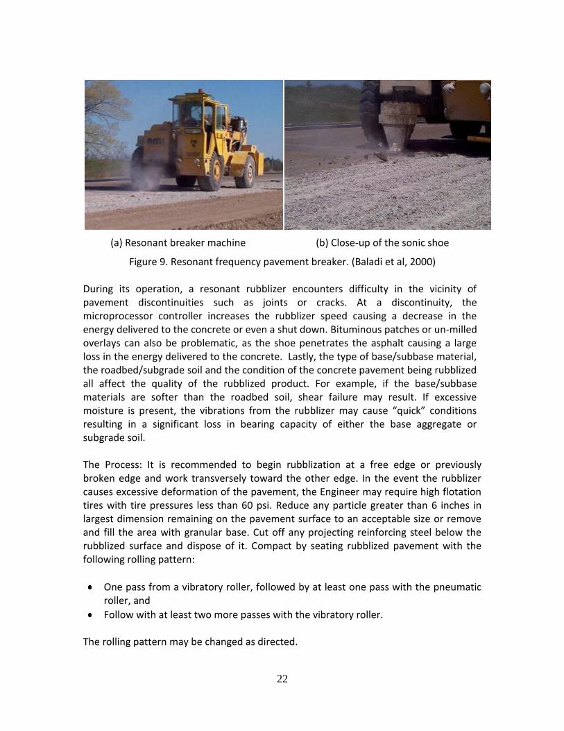
For slabs 14 in. thick: Erub ranges between 200 to 400 ksi. Buncher et al (2008) also reported data from field sections that resulted in average retained moduli values (Erub/EPCC) of about 6.0 percent. Further, thicker slabs exhibited higher retained moduli values than thinner PCC slabs. A summary of measured field moduli for rubblized PCC provided in the R23 Project Assessment Manual suggests a possible range of 40,000 to 700,000 psi with a more typical range of 50,000 to 150,000 psi. These values largely support those by Buncher. Rubblization is considered to be a viable, rapid, and cost-effective rehabilitation option for deteriorated PCC pavements. Good performance of rubblized pavements requires a high quality process of rubblization, effective rubblizing equipment, and maintaining a strong base and/or subgrade soil. Poor performance can occur when the underlying soils are saturated. Installation of edge drains prior to rubblization has proven to be successful for this type of condition. If the existing concrete pavement is deteriorated due to poor subgrade support, then rubblization is unlikely a viable option. Two types of equipment are used in the rubblization process: (1) resonant breaker and (2) multiple-head breaker. The resonant breaker (Figure 9) is composed of a sonic shoe (hammer) located at the end of a pedestal, which is attached to a beam—whose dimensions vary from one machine to another—and a counter-weight situated on top of the beam. The principle on which the resonant breaker operates is that a low amplitude (about 0.5-inch) high frequency resonant energy is delivered to the concrete slab, which causes high tension at the top. This causes the slab to fracture on a shear plane inclined at about 35-degrees from the pavement surface. Several equipment variables affect the quality of the rubblization process including: shoe size, beam width, operating frequency, loading pressure, velocity of the rubblizer, and the degree of overlapping of the various passes. The rate of production depends on the type of base/subbase material and is approximately 1.0 to 1.5 lane-miles/day.
22
(a) Resonant breaker machine
(b) Close-up of the sonic shoe
Figure 9. Resonant frequency pavement breaker. (Baladi et al, 2000) During its operation, a resonant rubblizer encounters difficulty in the vicinity of pavement discontinuities such as joints or cracks. At a discontinuity, the microprocessor controller increases the rubblizer speed causing a decrease in the energy delivered to the concrete or even a shut down. Bituminous patches or un-milled overlays can also be problematic, as the shoe penetrates the asphalt causing a large loss in the energy delivered to the concrete. Lastly, the type of base/subbase material, the roadbed/subgrade soil and the condition of the concrete pavement being rubblized all affect the quality of the rubblized product. For example, if the base/subbase materials are softer than the roadbed soil, shear failure may result. If excessive moisture is present, the vibrations from the rubblizer may cause “quick” conditions resulting in a significant loss in bearing capacity of either the base aggregate or subgrade soil. The Process: It is recommended to begin rubblization at a free edge or previously broken edge and work transversely toward the other edge. In the event the rubblizer causes excessive deformation of the pavement, the Engineer may require high flotation tires with tire pressures less than 60 psi. Reduce any particle greater than 6 inches in largest dimension remaining on the pavement surface to an acceptable size or remove and fill the area with granular base. Cut off any projecting reinforcing steel below the rubblized surface and dispose of it. Compact by seating rubblized pavement with the following rolling pattern:
One pass from a vibratory roller, followed by at least one pass with the pneumatic roller, and
Follow with at least two more passes with the vibratory roller.
The rolling pattern may be changed as directed.

23
The multi-head breaker operation includes multiple drop hammers arranged in two rows on a self-propelled unit and a vibratory grid roller (Figure 10). The bottom of the hammer is shaped to strike the pavement on 1.5 in. wide and 8 in. long loading strips. The hammers in the first row strike the pavement at an angle of 30 degrees from the transverse direction. The hammers in the second row strike the pavement parallel to the transverse direction. The sequence of hammer drops is irregular because each cylinder is set on its own timer/frequency system. By disabling some cylinders, the width of the rubblized area can be varied from 3 to 13 ft. The vibratory grid roller (10 tons) follows the multi-head breaker to reduce the size of the broken concrete. The rate of production of the multi-head breaker depends on the type of base/subbase material and is about 0.75 to 1 lane-mile/10 hour shift. Several variables affect the rubblization process including: speed, height, weight and frequency of the drop hammers. The multi-head breaker encounters difficulties on weak or saturated subbase and/or roadbed soil, which fail in shear causing large concrete pieces to rotate and/or penetrate the underlying material. Such failure would result in poor pavement performance.
The Process: It is recommended to rubblize the entire lane width in one pass. Provide a screen to protect vehicles from flying particles. Reduce any particle greater than 6 in. in largest dimension remaining on the pavement surface to an acceptable size or remove and fill the area with granular base. Cut off any projecting reinforcing steel below the rubblized surface and dispose of it. Compact by seating the pavement with the following rolling pattern:
A minimum of four passes with the Z-grid vibratory roller
Followed by four passes with a vibratory roller, and
At least two passes from a medium weight pneumatic roller
The rolling pattern may be changed as directed.
(a) Multi-head breaker
(b) Grid roller
Figure 10. Multi-head pavement breaker. (Baladi et al., 2000)

24
Figure 11 shows examples of good and poor rubblization outcomes.
(a) Rubblized Layer from MHB
(b) Rubblized Layer from RMI
(c) Partial debonding of temperature steel
(d) Partial destruction of the joint integrity
Figure 11. Examples of rubblized concrete pavements. (Sebesta and Scullion, 2007 and Baladi et al., 2000)
Rubblized Concrete Size Requirements Construction related problems with non-uniform particle size distribution throughout the PCC slab thickness will lead to underperforming pavements. Also, pavement sections that have been “over rubblized” (i.e., with rubblized pieces less than 2 inches in size) have a higher probability of cracking prematurely. Table 5 summarizes size requirements by various state highway agencies in the US. In addition, recent rubblization particle size information was summarized for the Wisconsin DOT (WisDOT, 2010). The results available in Table 5 and those from WisDOT differ somewhat; thus, the information shown must be used with significant judgment.
Table 5. Size requirements by various state highway agencies.

25
Agency No reinforcement
Top half of slab (or above reinforcement)
Bottom half of slab (or below reinforcement)
Michigan d < 8 in 2 in < d < 5 in d ≤ 8 in
Arkansas
d < 6 in 100% @ d ≤ 8 in 51% @ 1 in < d < 3 in
d < 6 in 100% @ d ≤ 8 in 51% @ 1 in < d < 3 in
d < 6 in 100% @ d ≤ 8 in 51% @ 1 in < d < 3 in
Illinois See next columns 75% @ d ≤ 3 in 100% @ d ≤ 9 in
75% @ d ≤ 9 in 100% @ d ≤ 12 in
Ohio N/A 100 % @ d < 6 in 100% @ 1 in < d < 2 in
100 % @ d < 6 in 51% @ 1 in < d < 2 in
Pennsylvania d < 6 in 100% @ d ≤ 8 in 51% @ d ≤ 4 in
d < 6 in 100% @ d ≤ 8 in 51% @ d ≤ 4 in
d < 6 in 100% @ d ≤ 8 in 51% @ d ≤ 4 in
Indiana d < 6 in 51% @ 1 in < d < 2 in
d < 6 in 100% @ 1 in < d < 2 in
d < 6 in 51% @ 1 in < d < 2 in
Texas (2004) See next columns
75% @ d < 4 in 100% @ d < 6 in
100% @ d < 12 in
FAA 75% @ d ≤ 3 in d ≤1.25 D
75% @ d ≤ 3 in d ≤1.25 D
75% @ d ≤ 12 in 100% @ d ≤ 15 in
Note: d=dimension of rubblized concrete pieces, D=depth of existing concrete.
Suitability for Rubblization
The collection of the pavement evaluation data allows the project to be analyzed for its suitability for rubblization. Performing the following steps enables making this determination (Sebesta and Scullion, 2007):
Evaluate the DCP data using a modified version of the IDOT rubblization selection chart (shown in Figure 12) as follows: o Plot the concrete thickness versus the CBR of the base. These data are used to
gauge whether the concrete will rubblize, since sufficient support beneath the slab is crucial for satisfactory breakage.
o Plot the combined thickness of the concrete and base versus the CBR of the subgrade. Use a “dummy” base layer of 6 inches if the DCP data do not distinguish a base layer. These data are used to evaluate whether the subgrade can support construction traffic after rubblization.

26
High risk for rubblization should translate to moderate risk for crack and seat, and moderate risk for rubblization should translate to low risk for crack and seat (and saw-cut, crack and seat).
Figure 12. Modified IDOT rubblization selection chart as proposed by TTI-TxDOT. (Sebesta and Scullion, 2007)
If all the data points fall in the zones that indicate rubblization is feasible, the project should be suitable for rubblization.
If all the data points fall in the High Risk zone of the chart, rehabilitation options other than rubblization (crack and seat for JPCP, sawcut and crack and seat for JRCP) should be considered.
If some, but not all, of the data points fall in the High Risk zone, certain portions of the project may not be suitable for rubblization. More analysis, interpretation, and judgment are required. Typically these instances are encountered on older concrete pavements where there is no or insufficient base support. Perform additional analysis as follows: o Determine the average CBR of the first 12 inches beneath the concrete. o From the rubblization selection chart, determine the minimum CBR necessary to
support rubblization for the known concrete thickness at the project. Do this by starting on the Y-axis at the known concrete thickness, then project horizontally until intersecting the boundary where rubblization is feasible. At this intersection, project down to the X-axis, and read the minimum subgrade CBR required.
o Form a relationship between the subgrade modulus and CBR by graphing the average CBR of the first 12 inches beneath the concrete versus the subgrade

27
modulus. Input the minimum CBR necessary into this relationship to determine the anticipated minimum subgrade modulus needed. Typically this modulus value ranges between 10 and 15 ksi.
o Graph the subgrade modulus with distance for the project. Where the modulus does not exceed the minimum subgrade modulus needed, a risk exists that the project may not rubblize. At this point the data must be reviewed on a case-by case basis and a judgment made as to where, if at all, rubblization should be attempted. Rehabilitation options other than rubblization (crack and seat for JPCP, saw-cut and crack seat for JRCP) should be considered.
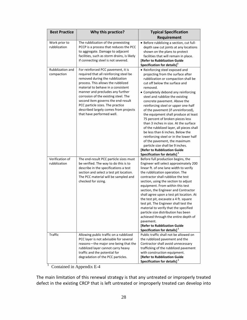
HMA over Rubblized PCC Pavement and Specifications A selection of significant practices associated with paving HMA over existing rubblized PCC pavement are included in Table 6. The table includes a brief explanation why the issue is of special interest along with examples from the study guide specification recommendations. Four major practices are featured: (1) work needed prior to rubblization, (2) the rubblization process and associated compaction, (3) verification of rubblization, and (4) traffic control.
HMA over CRC Pavements
Criteria for Long Life Potential
The combination of a CRC pavement and an HMA overlay has significant potential to provide long life pavement. This is because a CRC pavement eliminates moving joints within the concrete slab as it develops narrow transverse cracks at a regular spacing. If these cracks remain tight, then no reflection cracking should appear in the overlay as long as the surface of the existing CRCP is in good condition and a good bond between the HMA overlay and the CRCP is achieved. Also, in principle, this solution should lead to thinner overlays compared to HMA over existing jointed concrete pavements. This renewal solution is viable as long as the following critical features are met:
The surface condition of the CRCP is good (i.e., the deflection is low and there are no major defects such as spalling, punchouts, depressions and broken reinforcement).
There is no evidence of pumping underneath the existing slabs.
The foundation support is good (i.e., there are no voids between the concrete slab and the underlying base/subbase).
The existing drainage system is in good working condition or a drainage system can be put in place.
Table 6. Best practices and specifications for HMA over rubblized jointed plain PCC
pavement.
28
Best Practice Why this practice? Typical Specification Requirement
Work prior to rubblization
The rubblization of the preexisting PCCP is a process that reduces the PCC to aggregate. Damage to adjacent facilities, such as storm drains, is likely if connecting steel is not severed.
Before rubblizing a section, cut full-depth saw cut joints at any locations shown on the plans to protect facilities that will remain in place.
[Refer to Rubblization Guide Specification for details]
1
Rubblization and compaction
For reinforced PCC pavement, it is required that all reinforcing steel be removed during the rubblization process. This allows the rubblized material to behave in a consistent manner and precludes any further corrosion of the existing steel. The second item governs the end-result PCC particle sizes. The practice described largely comes from projects that have performed well.
Reinforcing steel exposed and projecting from the surface after rubblization or compaction shall be cut off below the surface and removed.
Completely debond any reinforcing steel and rubblize the existing concrete pavement. Above the reinforcing steel or upper one-half of the pavement (if unreinforced), the equipment shall produce at least 75 percent of broken pieces less than 3 inches in size. At the surface of the rubblized layer, all pieces shall be less than 6 inches. Below the reinforcing steel or in the lower half of the pavement, the maximum particle size shall be 9 inches.
[Refer to Rubblization Guide Specification for details]
1
Verification of rubblization
The end-result PCC particle sizes must be verified. The way to do this is to describe in the specifications a test section and select a test pit location. The PCC material will be sampled and checked for sizing.
Before full production begins, the Engineer will select approximately 200 linear ft. of one lane width to verify the rubblization operation. The contractor shall rubblize the test section, using the section to adjust equipment. From within this test section, the Engineer and Contractor shall agree upon a test pit location. At the test pit, excavate a 4 ft. square test pit. The Engineer shall test the material to verify that the specified particle size distribution has been achieved through the entire depth of pavement. [Refer to Rubblization Guide Specification for details]
1
Traffic Allowing public traffic on a rubblized PCC layer is not advisable for several reasons—the major one being that the rubblized layer cannot carry heavy traffic and the potential for degradation of the PCC particles.
Public traffic shall not be allowed on the rubblized pavement and the Contractor shall avoid unnecessary trafficking of the rubblized pavement with construction equipment. [Refer to Rubblization Guide Specification for details]
1
1 Contained in Appendix E-4
The main limitation of this renewal strategy is that any untreated or improperly treated defect in the existing CRCP that is left untreated or improperly treated can develop into
29
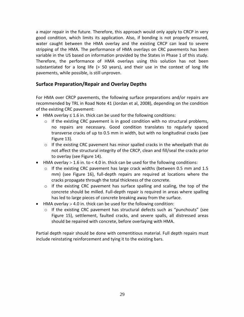
a major repair in the future. Therefore, this approach would only apply to CRCP in very good condition, which limits its application. Also, if bonding is not properly ensured, water caught between the HMA overlay and the existing CRCP can lead to severe stripping of the HMA. The performance of HMA overlays on CRC pavements has been variable in the US based on information provided by the States in Phase 1 of this study. Therefore, the performance of HMA overlays using this solution has not been substantiated for a long life (> 50 years), and their use in the context of long life pavements, while possible, is still unproven.
Surface Preparation/Repair and Overlay Depths
For HMA over CRCP pavements, the following surface preparations and/or repairs are recommended by TRL in Road Note 41 (Jordan et al, 2008), depending on the condition of the existing CRC pavement:
HMA overlay ≤ 1.6 in. thick can be used for the following conditions: o If the existing CRC pavement is in good condition with no structural problems,
no repairs are necessary. Good condition translates to regularly spaced transverse cracks of up to 0.5 mm in width, but with no longitudinal cracks (see Figure 13).
o If the existing CRC pavement has minor spalled cracks in the wheelpath that do not affect the structural integrity of the CRCP, clean and fill/seal the cracks prior to overlay (see Figure 14).
HMA overlay 1.6 in. to < 4.0 in. thick can be used for the following conditions: o If the existing CRC pavement has large crack widths (between 0.5 mm and 1.5
mm) (see Figure 16), full-depth repairs are required at locations where the cracks propagate through the total thickness of the concrete.
o If the existing CRC pavement has surface spalling and scaling, the top of the concrete should be milled. Full-depth repair is required in areas where spalling has led to large pieces of concrete breaking away from the surface.
HMA overlay 4.0 in. thick can be used for the following condition: o If the existing CRC pavement has structural defects such as “punchouts” (see
Figure 15), settlement, faulted cracks, and severe spalls, all distressed areas should be repaired with concrete, before overlaying with HMA.
Partial depth repair should be done with cementitious material. Full depth repairs must include reinstating reinforcement and tying it to the existing bars.

30
(a) closely spaced tight transverse cracks
(b) tight bifurcated cracks
Figure 13. Examples of minor cracks in CRCP. (Jordan et al. 2008)

31
(a) Spalled cracks
(b) Intersected crack pattern
Figure 14. Examples of major crack defects in CRCP. (Jordan et al. 2008)

32
(a) Punchout strip
(b) Severe punchout block
Figure 15. Examples of “punchouts” in CRCP. (Jordan et al. 2008)

33
HMA over Existing CRC Pavement and Specifications A significant issue associated with paving HMA over existing CRCP was selected and included in Table 7 full depth patching. The table includes a brief explanation why the issue is of special interest along with examples from the study guide specification recommendations.
Table 7. Best practices and specifications for HMA over existing continuously reinforced
PCC.
Best Practice
Why this practice? Typical Specification Requirement
Full depth patching process
The described steps are a systematic process for making any needed patches in the CRCP prior to resurfacing the existing pavement. The use of polyethylene sheets as a bond breaker is to reduce the amount of shrinkage related cracks.
Saw-cut full depth through the concrete around the perimeter of the repair area before removal.
Remove or repair loose or damaged base material, and replace or repair it with approved base material to the original top of base grade. Place a polyethylene sheet at least 4 mils thick as a bond breaker at the interface of the base and new pavement. Allow concrete used as base material to attain sufficient strength to prevent displacement during further construction.
Broom finish the concrete surface unless otherwise shown on the plans.
[Refer to Elements for AASHTO Specification 558 for more details]1
1 Contained in Appendix E-4
Added Lanes and Approaches for Adjacent Structures There is little guidance found in the literature on integrating the new or rehabilitated pavements into adjacent pavements and features. This section addresses adding lanes to an existing pavement structure as well as accommodating existing features such as bridge abutments and vertical clearance restrictions within the limits of a pavement renewal project. These issues are paramount when using the existing pavement in-place as part of long life renewal because there is typically a significant elevation change associated with each renewal alternative The following recommendations are based on discussions with the SHAs surveyed in Phase 1 and those agencies who participated in Phase 2.

34
Approaches to Undercrossing Structures, Bridges, and Overcrossing Structures All of the agencies that participated in the study indicated that a completely new roadway section was constructed as a transition between the in-place renewal cross-section and the existing feature. New pavement sections were constructed either approaching an overcrossing/bridge structure abutment or before passing under a structure where there is not sufficient clearance to meet standards. The length of this transition section depended upon the elevation difference, but was usually in the range of 200 to 400 ft. before and after the structure. Consideration of the longitudinal drainage is required when designing the transition section. Where possible, the existing subgrade elevation and grade should be maintained in the longitudinal direction as well as in the transverse direction. Because the new roadway section is generally not as thick as the renewal approach using the existing pavement, the elevation difference is usually made up with untreated granular base material. The elevation difference can often be accomplished by varying the thickness of that base layer. However, there are cases where there may be an advantage to replacing the existing PCC with HMA and only using one material to construct the transition for ease of staging, as shown below in Figures 16 and 17.
Figure 16. Diagram of transition to bridge approach
Figure 17. Diagram of transition beneath structure.

35
In some cases, Agencies reported that they were able to raise an overcrossing rather than reconstruct the roadway for less cost and reduced impact on traffic. That option may be considered where possible, particularly in more rural areas where there is little cross traffic on the overcrossing.
Added Lanes or Widening A project that calls for additional lanes or widening often facilitates the staging of the traffic through the project, but usually produces a mismatch in pavement sections in the transverse direction. The elevation and grade line of the subgrade should be maintained so that water flowing along the contact between the base and the subgrade does not get trapped in the transverse direction. There is a risk of reflection cracking between the existing pavement and the new pavement section, particularly when the existing pavement is a PCC pavement. Also of concern is the need for stabilizing the subgrade soil if required for widening. Subgrade stabilization will increase the stability of the roadway section, accelerate pavement construction, and help to reduce some of the settlement or differential vertical deflection that causes reflection cracking along the contact with the old PCC pavement. Specifically, the SHRP 2 guidance for "Geotechnical Solutions for Transportation Infrastructure" and their recommendations for stabilization of the pavement working platform should be considered.
Widening Next to Rubblized PCC Pavement
Since the rubblized PCC pavement is basically turned back into a form of gravel, there has been little in the way of complications widening these pavement sections. Where the shoulder is not full depth gravel to the subgrade contact (as shown in Figure 18), it is recommended that the shoulder be removed to the subgrade contact and the section next to the rubblized PCC pavement be replaced with untreated granular base. This will ensure that water flowing transversely along the base/subgrade interface will not get trapped under the pavement structure. If the subgrade soils need to be stabilized, then that should take place before backfilling with untreated granular base; however, where soils are weak and wet enough to require stabilization, they may not be stable enough to allow rubblization. Depending on the widening needs, there may be cases where the shoulder is reconstructed and used to carry traffic while the existing PCC pavement is being rubblized. In cases where the HMA is placed next to the PCC pavement prior to rubblization, the lateral restraint aids rubblization. The thickness of the HMA placed next to the existing PCC pavement depends on the traffic loading during staging and the amount of construction traffic that would use the widened lane before the final overlays are placed.

36
Figure 18. Showing existing PCC pavement.
Figure 19 shows the design roadway section with free draining granular base extending either to the in slope of the ditch or the fill slope (i.e., "daylighting") to provide drainage. An agency may elect to use internal drainage where longitudinal drains are installed just outside of the traveled lane. Either drainage approach is acceptable as long as some form of drainage is provided.
Figure 19. Illustration of widening the shoulder with daylighting or drainage installed.
Widening Next to Cracked and Seated or Saw Cracked and Seated PCC Pavement Widening next to cracked and seated PCC pavement is treated much the same as described for rubblized PCC, except there is a risk that a longitudinal reflection crack may form along the edge of the existing PCC pavement. This is most likely caused by the differential vertical deflection found between the rigid pavement and the more flexible adjacent pavement. The deflection difference can be reduced by a number of options. The first consideration would be to stabilize the subgrade soil in the widened area. Even where stabilization is marginally indicated, it may be advisable to stabilize the subgrade to facilitate construction and reduce the differential deflection between the two pavement sections.
37
When overlaying cracked and seated PCC pavement with HMA, most States interviewed have used HMA in the widening for economic reasons. Again, the thickness of the HMA placed next to the existing PCC pavement will depend on the amount of traffic loading expected during the staging. The final thickness of the HMA in the widened lane will depend upon the total thickness design for the traffic in that lane, or a combination of that required to accommodate traffic before the overlay and the thickness of the overlay, whichever is greater. In some cases, the use of an Interlayer Stress Absorbing Composite (ISAC) may reduce the amount of reflection cracking along the longitudinal joint between the existing PCC pavement and the HMA widening (Hoierner, et al, 2001).
Structural Design Criteria to Achieve Long Life
Basic Approach
The most accepted approach to designing HMA long life pavements is to use mechanistic-empirical concepts as described by Monismith (1992). The basis of this approach is that pavement distresses with deep structural origins could be avoided if pavement responses such as stresses, strains, and deflections could be kept below thresholds (endurance limits) where the distresses begin to occur. Thus, an asphalt pavement could be designed for an “indefinite” structural life by designing for the heaviest vehicles without being overly conservative (Thompson and Carpenter, 2004; Timm and Newcomb, 2006). The basic concept of a long life HMA pavement is illustrated in Figure 20 (Newcomb et al, 2010). This approach can be extended to HMA renewal solutions.
Endurance Limits Suggested values for the horizontal tensile strain at the bottom of the HMA layer and vertical compressive strain at the top of the subgrade are 60 microstrains and 200 microstrains, respectively (Monismith and Long, 1999). The value for the endurance limit of the tensile strain at the bottom of the HMA layer is still debated. Original work by Monismith and others suggests a value of 60 microstrains, but currently accepted values range from 70 to 100 microstrains (Thompson and Carpenter, 2004). Research at NCAT suggests even higher fatigue endurance limits could be possible (Willis et al., 2009).
Pavement Design Software In principle, adopting the limiting strain criteria for design allows for using any layered elastic analysis computer program, since the main output needed is the strain values at specific depths. However, a program that was developed specifically for the purpose of design long life HMA pavements is the PerRoad software (Timm, 2008). The program

38
uses the basic M-E design philosophy and couples layered elastic analysis with a statistical analysis procedure (Monte Carlo simulation) to predict stresses and strains within a pavement (Timm and Newcomb, 2006). The Monte Carlo simulation allows for incorporating variability into the analysis to more realistically characterize the pavement performance. PerRoad requires the following inputs:
Figure 20. Long life HMA pavement design concept. (Newcomb et al., 2010)
Seasonal pavement moduli and annual coefficient of variation (COV)
Seasonal resilient moduli of unbound materials and annual COV
Thickness of bound materials and COV
Thickness of unbound materials
Load spectrum for traffic (or ESAL equivalents)
Location for pavement response analysis
Magnitude of limiting pavement responses
Transfer functions for pavement responses The output for PerRoad consists of an evaluation of the percentage of load repetitions lower than the limiting pavement responses specified in the input, an estimate of the amount of damage incurred per single axle load, and a projected time to when the accumulated damage is equal to 0.1 (D = 1.0 is considered failure). On high volume pavements, the critical parameter is the percentage of load repetitions below the

39
limiting strains. It is generally recommended that the designer strive for a value of 90 percent or more on high volume roads. PerRoad 3.5 (Timm, 2008) may also be used to design asphalt pavements over fractured concrete pavements. This only requires that the second layer be specified as rubblized, cracked and seated, or broken and seated concrete pavement. Beyond that, it follows the same mechanistic design process for a long life HMA pavement as described above. The AASHTO Mechanistic-Empirical Pavement Design Guide (AASHTO, 2008) can be used for long life pavement design, by using the option of selecting a fatigue endurance limit ranging between 75 and 250 microstrains. Willis and Timm (2009) found good agreement between PerRoad and the MEPDG in terms of thickness requirements when the fatigue endurance limit was used. [During June 2011, the MEPDG was released by AASHTO as Darwin-ME.]
In the MEPDG software, the elastic modulus of the rubblized PCC is assigned a modulus of 150 ksi for Level 3 design (the simplest approach, requiring the fewest and simplest user inputs). For Level 1 design (the most sophisticated approach, requiring the most numerous and precise user inputs), however, the rubblized PCC modulus may be assigned a value from 300 to 600 ksi, depending on the expected level of control on the breaking process, and the anticipated coefficient of variation of the fractured slab modulus.
Example Designs
The following long life examples are cited in the synthesis by Newcomb et al (2010). HMA “Mill and fill” Overlay over Existing HMA Pavement The rehabilitation of I-287 in New Jersey is an excellent example of the process for evaluation and design of an overlay to an existing pavement. The 26 year old pavement structure was a 10 in. thick asphalt pavement that had received a minimum of maintenance. The New Jersey DOT investigation of distresses that developed on the surface showed fatigue cracking, longitudinal cracking in the wheelpaths, and ruts deeper than one inch (Fee, 2001). A detailed examination of the pavement structure showed that none of the distresses extended more than 3 in. deep into the HMA. The pavement subsequently had the top 3 in. milled and replaced with 4 in. of HMA surfacing. This work was done in 1994, and a pavement survey done in 2001 showed no signs of cracking or rutting (Rowe et al., 2001).

40
HMA Overlay over Fractured PCC Pavement HMA over Crack and Seat PCC. Most of the I-710 freeway project in California consisted of a 9 in. thick asphalt overlay (8 in. of dense graded HMA capped with a one inch open graded wearing course) on a cracked and seated concrete pavement (Monismith and Long, 1999b, Monismith et al, 2009a and 2009b). The HMA overlay does not have a more fatigue resistant bottom layer (often referred to a “rich bottom” layer), since the cracked and seated concrete provides a stiff foundation for the asphalt and prevents the excessive bending associated with bottom-up fatigue cracking. An asphalt-saturated fabric was placed over a one inch leveling course on top of the concrete to resist reflective cracking. HMA over Rubblized JPCP. Von Quintus and Tam (2001) developed a procedure for designing long life asphalt pavements over rubblized concrete for Michigan that followed the same approach they used for asphalt pavements. The thicknesses for these asphalt pavements varied depending on design period and traffic levels, with mill and fill rehabilitation assumed at years 20 and 32. Table 8 shows the total HMA thickness along with HMA mix type recommended for the surface course. Table 8. Michigan design catalog for long life HMA pavements over rubblized concrete.
(after APA, 2002; Von Quintus and Tam, 2001)
Design Period (years)
Total HMA Thickness (in.) and Type of Surface Mix (as a function of 20 year ESALs)
3 million 10 million 20 million 30 million
20 6.0 8.5 10.6 11.4
Superpave Superpave SMA SMA
30 7.0 10.0 12.0 13.0
Superpave Superpave SMA SMA
40 8.5 10.6 13.0 14.6
Superpave Superpave SMA SMA
HMA over Rubblized CRCP. A portion of the I-5 experimental project in Oregon consists of a 12 in. thick HMA layer over an 8 in. thick rubblized CRCP and a jointed reinforced concrete pavement (JRCP) (Renteria and Hunt, 2006; Sholz et al., 2006). The test site located on the JRCP is instrumented to monitor pavement responses and environmental conditions.
Minimum HMA Thicknesses
TRL Road Note 41 (Jordan et al. 2008) recommends the following minimum HMA overlay thicknesses for the various HMA over concrete pavement renewal approaches:

41
For HMA over cracked and seated (or sawed, cracked-and-seated) concrete pavements, TRL recommends a minimum HMA overlay thickness of 6 in.
For HMA over rubblized concrete pavements, TRL recommends a minimum HMA overlay thickness of 8 in., but with the expectation that overlays for rubblized PCC will be significantly higher than that for cracked and seated pavements. HMA thicknesses over rubblized PCC range up to 17 in. thick based on TRL Road Note 41.
For HMA over CRCP pavements (as noted previously), TRL recommends the following HMA overlay thicknesses, depending on the condition of the existing CRC pavement, and with the proper repairs done to distressed areas before overlaying (see CRCP section above): o A thin overlay (about 2 in. or less) can be used when:
The existing CRC pavement is in good condition with no structural problems, but may have an unacceptable level of skid resistance and/or surface noise characteristics.
The existing CRC pavement has minor spalled cracks in the wheelpath that do not affect the structural integrity of the CRCP.
o A medium overlay (about 2 to 4 in.) can be used when: The existing CRC pavement has large crack widths (between 0.5 mm and 1.5
mm). The existing CRC pavement has surface spalling and scaling.
o A thick overlay (greater than 4 in.) should be used when: The existing CRC pavement has localized deformation and settlement due to
poor subgrade condition. The existing CRC pavement has structural defects such as “punchouts”,
settlement, faulted cracks, and severe spalls. The existing CRC pavement needs strengthening to accommodate higher
traffic loading levels. Broadly, for HMA overlays over processed PCC, thicknesses will typically be in the range of 8 to 10 in. for long life pavements. Many agencies will find this level of thickness costly; however, the issue is whether to spend more initially, minimizing future costs, or to enter into an endless cycle of rehabilitation and marginal pavement performance.
HMA Mix Design Criteria to Achieve Long Life Achieving long life HMA pavement solutions requires the combination of a rut/wear resistant top layer with a rut resistant intermediate layer and a fatigue resistant base layer. A high quality HMA wearing surface or an open graded friction course, a thick, stiff dense graded intermediate layer and a flexible (asphalt rich) bottom layer is recommended. However, the experience from the States would indicate that the rich bottom layer is not required as long as there is sufficient HMA depth and a strong enough foundation to satisfy the limiting strain criteria.

42
Surface Course The surface course layer should be able to withstand high traffic and environment induced stresses without surface cracking or rutting. It should also possess a texture that ensures adequate skid resistance and low tire-pavement noise emission, and a structure that would allow for mitigation of splash and spray. No single material can provide all the desired characteristics since these tend to compete against each other (e.g., open-graded mixtures are excellent for drainage but are generally not durable, especially in wet-freeze environments). Possible solutions include stone matrix asphalt (SMA), an appropriate Superpave dense-graded mixture, or open-graded friction course. Guidance on mix type selection can be found in Newcomb and Hansen (2006) as shown in Figure 21.
Figure 21. Mix type selection guide for long life HMA pavements. (Newcomb and Hansen, 2006)

43
For heavily trafficked roads, the need for rutting resistance, durability, impermeability, and wear resistance would dictate the use of SMA (EAPA (2007), Michael et al (2005)). This might be especially true in urban areas with high truck traffic volumes. When properly designed and constructed, an SMA mix will provide a stone skeleton for the primary load carrying capacity and the matrix (combination of binder and filler) gives the mix additional stiffness. European experience has shown that SMA tends to exhibit the best performance (high durability, good skid resistance, and low noise emission) as compared to a range of hot mix types. A study from the European Asphalt Pavement Association (EAPA, 2007), found SMA mixtures to have an average life of 20 years, while traditional hot mixes averaged 15 years. Similar performance trends were noted by those Agencies who regularly use SMA in their paving program. Methods for SMA mix design are given in NCHRP Report No. 425 (Brown and Cooley, 1999). The matrix in an SMA can be obtained by using polymer-modified asphalt, fibers, or specific mineral fillers. The use of fibers is beneficial to preclude drain-down. Care should be taken in controlling the aggregate gradation, especially on the 4.75 mm and 0.75 mm sieves (Brown and Cooley, 1999). For lower truck traffic levels, the use of a well-designed, dense-graded Superpave mixture could be warranted. Similarly to SMA, these mixes should be designed against rutting, permeability, weathering, and wear. The Asphalt Institute (1996b) provides guidance on the volumetric proportioning of Superpave mixtures. It is recommended that a performance test of dense-graded mixtures, whether SMA or Superpave, be done during mixture design. At a minimum, a rut test should be conducted (Brown et al., 2001). The two most common HMA rut tests are the Hamburg Wheel Track Test (AASHTO T 324) and the Asphalt Pavement Analyzer (AASHTO TP 63). Later in this document (“HMA Stripping—Causes, Assessment, Solutions”), the Hamburg test is discussed in additional detail (note Figure 26 within that section). In western and southern regions of the United States, open-graded friction courses (OGFC) are used to improve wet-weather friction. Some northern states such as Massachusetts, New Jersey, and Wyoming use OGFC as well. These mixes are designed to have voids that allow water to drain from the roadway surface. Void contents as high as 18 to 22 percent can provide good long-term performance (Huber, 2000). Fibers can be used to help resist drain-down of the asphalt during construction, and polymer-modified asphalt will help in providing long-term performance (Huber, 2000). The mix design for OGFC can be done using the method that has been developed by Kandhal and Mallick (1999). Kandhal (2001) also gives guidance on the construction and maintenance of OGFC surfaces. This type of mix enhances safety, but is likely to require more frequent rehabilitation than dense graded HMA mixes, in part, due to clogging of the voids.

44
The PG grade used in the asphalt mix should be appropriate for the climate and traffic in a given area, consistent with Superpave practice. The LTPPBind software should be used to provide guidance on the proper grade of asphalt if local guidance is not available (LTPP, 2010). Normally, 95 percent or 99 percent reliability should be used, depending upon availability and cost. Other notable HMA mix issues that should be considered for long life performance include:
Nominal Maximum Aggregate Size (NMAS) SMA gradations of 4.75 or 9.5 mm are a viable option for thin overlays. These mixes are rut resistant and exhibit low permeability (Cooley and Brown, 2003; Newcomb, 2009). Thin overlays could be considered for the periodic resurfacing that is needed for HMA wearing courses.
The permeability levels are lower for SMA and fine-graded dense mixes according to Brown et al, 2004 (fine-graded for the NCAT study was defined as 12.5 mm NMAS
mixes with 40 percent passing a 2.36 mm sieve).
Recent research studies investigated the use of lower gyration levels for designing SMA mixtures and indicate that 50 to 75 gyrations work well and should be used for SMA mix design (Timm et al, 2006). Further, when fine-graded dense mixes were compared to coarse-graded dense mixes, they exhibited an equal resistance to rutting, were less likely to be permeable, were quieter, had similar friction values, were somewhat easier to compact, and had higher optimum asphalt contents (higher asphalt contents are a plus to combat aging, but the mix will cost more).
Use of RAP in HMA reduces mix cost (Mamlouk and Zaniewski, 2011).
On the basis of results obtained by two NCAT studies (Mallick et al, 2003 and Brown et al, 2004), the following conclusions were drawn:
o The air void level of dense graded HMA has a significant effect on in place
permeability of pavements. This is not a new finding, but it is important to emphasize.
o The nominal maximum aggregate size (NMAS) can have a significant effect on the permeability of coarse graded Superpave designed mixes. Further, as the NMAS increased, the permeability increased by one order of magnitude. This finding is significant when choosing a wearing course gradation.
o Fine graded mixes are less permeable than coarse graded mixes for the same field air void level.
o Increasing the layer thickness decreases the mix permeability.
Binder (Intermediate) Course
The intermediate or binder layer should be designed for stability and durability. Stability can be obtained by achieving stone-on-stone contact in the coarse aggregate and using the appropriate high-temperature grading for the binder. This is especially crucial in the

45
top four inches of the pavement, where high stresses induced by wheel loads can cause rutting through shear failure. Two options to reduce cost (by lowering the asphalt content) are to use large-stone mixtures (Kandhal, 1990; and Mahboub and Williams, 1990) and to consider the use of RAP. The Superpave mix design approach (Asphalt Institute, 1996b) may be used for mixtures with a nominal maximum aggregate size up to 37.5 mm. However, the use of large nominal aggregate size may lead to segregation and higher-than-desirable air voids, which can lead to the intrusion of water. Requiring a lower void content in mix design, and ensuring a high level of compaction in the field are measures to mitigate against these undesirable outcomes. Smaller aggregate sizes can also be used, as long as stone-on-stone contact is maintained. The mix design should be a standard Superpave approach (Asphalt Institute, 1996b) with a design air voids level appropriate for insuring low permeability. One test for evaluating whether stone-on-stone interlock exists is the Bailey method (Vavrik et al., 2001). The high-temperature PG grade of the asphalt should be the same as for the surface to resist rutting. However, the low temperature requirement could probably be relaxed one grade, since the temperature gradient in the pavement is relatively steep and the low temperature in this layer would not be as severe as for the surface layer (Newcomb, et al, 2010). The LTPPBind Software can be used to determine the proper asphalt binder grade for each layer (LTPP, 2010). It is recommended that a performance test of dense-graded mixtures be performed during mixture design. At a minimum, this should consist of rut testing (Brown et al., 2001).
Base Course The asphalt base layer must resist against fatigue cracking. The notion of fatigue endurance limit discussed above suggests that at low levels of strain, there is an appreciable change to the fatigue relationship resulting in less damage per cycle. This is in part, due to healing, a lack of crack propagation, and non-linearity in fatigue relationships. Proper consideration should be given to the effects of temperature, aging, healing, and mixture composition. The predominant mix design approach to resist fatigue cracking in the US is to use a higher asphalt content, which (1) allows the material to be compacted to a higher density, and in turn, improve its durability and fatigue resistance, and (2) provides the flexibility needed to inhibit the formation and growth of fatigue cracks. When combined with an appropriate total asphalt thickness, this helps ensure against fatigue cracking from the bottom layer. An alternative method to achieve high resistance against fatigue cracking is to design for an asphalt content, which produces low air voids in place. This
46
ensures a higher volume of binder in the voids in mineral aggregate (VMA), which is critical to durability and flexibility. Fine-graded asphalt mixtures have also been shown to have improved fatigue life (Epps and Monismith, 1972). However, care should be taken to insure proper rut resistance during construction if this layer is to be opened to traffic during construction (Newcomb et al., 2010). In Europe, the concept of high-modulus pavements has been used, particularly in England and France. This solution allows for using less material and reducing the cost of long life HMA pavements. In this design approach, a very stiff asphalt mixture is used as the base and intermediate layers. In these pavements, the base course mix is made with a stiff binder combined with a relatively high binder content and low void content. This allows for a reduction in thickness between 25 and 30 percent in the pavement structure (EAPA, 2009). Because the base layer is most likely to be in prolonged contact with water, moisture susceptibility needs to be considered. A higher asphalt content, which would increase the mix density, should enhance the mixture's resistance to moisture problems, but it is advisable to conduct a moisture susceptibility test during the mix design (Newcomb et al., 2010). HMA stripping resistance is critical for long-lasting HMA renewal solutions. As such, content about its causes, assessment, and currently applied solutions follows.
HMA Stripping—Causes, Assessment, Solutions
Introduction and Background
The presence of moisture combined with repetitive traffic can adversely affect the performance of asphalt pavements. Moisture damage is caused by a loss of adhesion or “stripping” of the asphalt film from the aggregate surface as shown in Figure 22. Moisture damage may also be caused by a loss of cohesion within the asphalt binder itself, resulting in a reduction in asphalt mix stiffness. Furthermore, heavy traffic on a moisture-weakened asphalt pavement can result in premature rutting or fatigue cracking as shown in Figure 23. The presence of moisture can also accelerate the formation of potholes or promote delamination between pavement layers (Figure 24) (Santucci (2002); Santucci (2010)). Moisture may enter the pavement in both liquid and vapor form: through the surface by precipitation, hydraulic pressure from tire action, and irrigation; and capillary rise of subsurface water. Moisture can also be present in the asphalt mix as a result of inadequately dried aggregate.

47
Figure 22. Moisture-induced stripping. (Photo courtesy Rita Leahy)
Rutting Fatigue cracking
Figure 23. Moisture-weakened asphalt pavement induces premature failure. (Photo
courtesy Rita Leahy)
Pothole Delamination
Figure 24. Moisture exacerbates local pavement distress.

48
Factors that contribute to moisture-related distress in asphalt pavements are summarized in Hicks et al (2003). The physical and chemical characteristics of aggregates play a major role in the resistance of asphalt pavements to moisture damage. Physical properties such as shape, surface texture, and gradation influence the asphalt content of the mix and hence the asphalt film thickness. Thick films of asphalt resist moisture damage better than thin films. Rough-textured aggregate surfaces provide better mechanical adhesion with the asphalt than smooth-textured surfaces. Surface chemistry of the aggregate is also important. Aggregates range from basic (limestone) to acidic (quartzite), while asphalt has a neutral to acidic tendency depending on the asphalt source. This suggests that asphalt adheres more readily to alkaline aggregates such as limestone than to acidic aggregates. Clay in the aggregate or present as a thin coating on the aggregate can contribute to moisture sensitivity problems. Clay expands in the presence of water and weakens the mix. As an aggregate coating, clay adversely affects the adhesive bond between the asphalt and aggregate surface. The surface chemistry of asphalt can be altered with additives such as anti-strip agents to enhance adhesion between the asphalt and aggregate. Physical properties of asphalt, such as viscosity and film thickness, are also important in preventing moisture damage. Complete coating of the aggregate surface during mixing is critical to prevent moisture infiltration at the asphalt-aggregate interface. Lowering the asphalt viscosity by raising mixing temperatures at the hot mix plant—or, in the case of warm mix asphalt, by using additives or foam technology—helps to ensure good coating of the aggregate. The lower asphalt viscosity allows deeper penetration into the interstices of the aggregate and thus results in a stronger physical bond between the asphalt and aggregate. The use of additives, such as polymers or rubber in asphalt, generally results in thicker films that help reduce the moisture sensitivity of the mix. Moisture is a concern during plant production as well. Moisture from inadequately dried aggregates can escape as steam as the asphalt mix is heated or stored, potentially leading to stripping of the asphalt film from the aggregate. In some instances, water has been observed in mixes at the base of hot mix storage silos and at the edge of windrows of hot mix placed on the roadway prior to paving (Santucci, 1985). Good construction practices can produce moisture resistant asphalt pavements. The most important factor is good compaction. Compacting dense graded asphalt mixes to a high density (93 to 96 percent of maximum theoretical density) lowers the air void content and permeability of the mix. Well compacted mixes are less susceptible to premature rutting, fatigue cracking, and binder oxidation, and thus provide a longer service life (Harvey et al [1996]; Blankenship [2009]).

49
Construction practices that trap moisture in pavement layers should be avoided. For example, placing an open graded mix over a dense graded pavement with depressions or ruts can result in collecting water on the surface of the underlying pavement unless adequate drainage is provided prior to the overlay. Placing a high air void content layer between two layers of low air void content should be avoided. Moisture can also accumulate at the interface of impermeable interlayers placed between dense graded asphalt pavement lifts or under chip seals placed over moisture sensitive mixes.
California Study Recent work done in California (Qing et al, 2007) is of special interest. Caltrans initiated and funded a study by the University of California Pavement Research Center (UCPRC) to conduct a statewide field investigation and laboratory testing to determine the severity and major factors associated with moisture damage. The study was conducted from September 2002 to September 2005. The laboratory testing determined the effect of variables such as air void and binder contents on moisture damage, and developed dynamic loading test procedures to evaluate moisture sensitivity. The effectiveness of the Hamburg Wheel Track Test (HWTT) and the long term effectiveness of hydrated lime and liquid anti-strip additives were also evaluated. The HWTT will be covered in more detail shortly. The field investigation surveyed the condition of 194 pavement sections located throughout California. The survey represented pavements encompassing a range of traffic and environmental conditions. The majority of the sections examined were dense graded HMA, and gap graded rubber modified asphalt concrete (R-HMA). Based on the condition survey results, 63 sections were selected for a more intensive analysis that included field permeability measurements and the recovery of cores for testing in the laboratory. About 10 percent of the pavement sections showed moderate to severe moisture damage. Air void content was found to be a major factor affecting moisture sensitivity. Dense graded HMA sections with air void contents of 7 percent or less showed little or no moisture damage. Sections with air void contents greater than 7 percent showed medium or severe moisture damage. Based on limited data, R-HMA sections did not show an advantage in moisture resistance over dense graded HMA using conventional binders. Severe stripping was observed on a few R-HMA sections with high air void contents. Another observation from the field survey was the importance of adequate pavement drainage systems. Drainage systems need to be well designed and maintained to ensure removal of water from the surface and within the pavement during rain events, since the amount of rainfall has a major effect on moisture damage. The HWTT was found to be an effective predictor, correlating reasonably well with field performance, although in some cases the procedure may fail mixes that perform well in

50
the field or give false positive results. Suggestions made to improve the prediction accuracy of the HWTT were: (1) use a test temperature consistent with the pavement location, and (2) when the standard wet test yields poor results, run the test in a dry condition. Based on both field and laboratory data, the researchers found hydrated lime and liquid anti-strip agents improved the moisture resistance of asphalt mixes. Hydrated lime and liquid anti-strip agents were also effective in improving moisture resistance during a conditioning period of up to one year. The effectiveness of the liquid anti-strip agents remained constant over the one year period while, in some instances, the hydrated lime showed increasing effectiveness over the same time period.
Tests to Predict Moisture Sensitivity The numerous tests developed to predict the moisture sensitivity of asphalt mixes can be grouped into three general categories:
Tests on mix components and component compatibility;
Tests on loose mix; and
Tests on compacted mix. Table 9 provides a summary of the tests used for moisture sensitivity. Component and Compatibility Tests Some of the more common tests used on asphalt mix components to determine the potential for moisture damage include the sand equivalent test, plasticity index, and the methylene blue test. Tests on Loose Mix These tests are conducted on asphalt coated aggregates in the presence of water. Examples include film stripping, immersion (static, dynamic, or chemical), surface reaction, Texas boiling water, and pneumatic pull-off tests. Advantages of tests on loose asphalt mix are that they are quick to run, cost little, and require simple equipment and procedures. Disadvantages are that the tests do not take into account traffic action, mix properties, and the environment. Results are mostly qualitative and require the subjective judgment and experience of the person performing the test. There is little evidence that results from these tests correlate well with field performance of asphalt mixes.
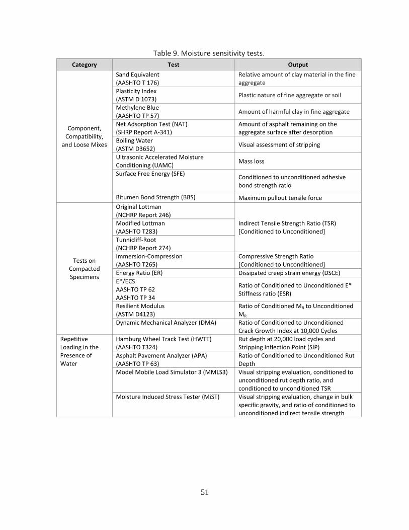
51
Table 9. Moisture sensitivity tests.
Category Test Output
Component, Compatibility,
and Loose Mixes
Sand Equivalent (AASHTO T 176)
Relative amount of clay material in the fine aggregate
Plasticity Index (ASTM D 1073)
Plastic nature of fine aggregate or soil
Methylene Blue (AASHTO TP 57)
Amount of harmful clay in fine aggregate
Net Adsorption Test (NAT) (SHRP Report A-341)
Amount of asphalt remaining on the aggregate surface after desorption
Boiling Water (ASTM D3652)
Visual assessment of stripping
Ultrasonic Accelerated Moisture Conditioning (UAMC)
Mass loss
Surface Free Energy (SFE) Conditioned to unconditioned adhesive bond strength ratio
Bitumen Bond Strength (BBS) Maximum pullout tensile force
Tests on Compacted Specimens
Original Lottman (NCHRP Report 246)
Indirect Tensile Strength Ratio (TSR) [Conditioned to Unconditioned]
Modified Lottman (AASHTO T283)
Tunnicliff-Root (NCHRP Report 274) Immersion-Compression (AASHTO T265)
Compressive Strength Ratio [Conditioned to Unconditioned]
Energy Ratio (ER) Dissipated creep strain energy (DSCE)
E*/ECS AASHTO TP 62 AASHTO TP 34
Ratio of Conditioned to Unconditioned E* Stiffness ratio (ESR)
Resilient Modulus (ASTM D4123)
Ratio of Conditioned MR to Unconditioned MR
Dynamic Mechanical Analyzer (DMA) Ratio of Conditioned to Unconditioned Crack Growth Index at 10,000 Cycles
Repetitive Loading in the Presence of Water
Hamburg Wheel Track Test (HWTT) (AASHTO T324)
Rut depth at 20,000 load cycles and Stripping Inflection Point (SIP)
Asphalt Pavement Analyzer (APA) (AASHTO TP 63)
Ratio of Conditioned to Unconditioned Rut Depth
Model Mobile Load Simulator 3 (MMLS3) Visual stripping evaluation, conditioned to unconditioned rut depth ratio, and conditioned to unconditioned TSR
Moisture Induced Stress Tester (MiST)
Visual stripping evaluation, change in bulk specific gravity, and ratio of conditioned to unconditioned indirect tensile strength

52
Tests on Compacted Mix A multitude of tests on compacted asphalt mixes have been developed and modified. The tests are run on laboratory compacted specimens, field cores, or slabs. Examples include moisture vapor susceptibility, immersion-compression, Marshall immersion, freeze-thaw pedestal, Lottman indirect tension (original and modified), Tunnicliff- Root, ECS/resilient modulus, and wheel tracking (Hamburg and Asphalt Pavement Analyzer) tests. Many of these tests compare the strength of the compacted mix after being exposed to defined conditions, such as temperature and freeze-thaw cycling, to the dry strength of the specimen. Advantages of these tests are that they consider traffic, mix properties, and the environment, and that they produce quantitative results rather than subjective evaluations. Disadvantages include longer testing times, elaborate and expensive testing equipment, and test procedures that are laborious. A survey conducted by the Colorado DOT in 2002 (referred to by Hicks, Santucci, and Ashenbrener (2003) and Solaimanian et al (2003)) revealed that most agencies used some version of retained strength tests on compacted mixes (Lottman, modified Lottman, Tunnicliff-Root, or immersion-compression) to determine moisture sensitivity of hot mix asphalt (Table 10). Despite the widespread use of AASHTO T283, the success rate of predicting moisture damage in the field has been limited, as shown in Table 11 (Kiggundu and Roberts, 1988). In some instances, the procedure fails mixes that have a long history of good field performance. Some critics of the Lottman-type procedures question the severity of the accelerated vacuum saturation step and its effect on the asphalt-aggregate bond. More recently, agencies have found greater success with the Hamburg Wheel Tracking Test (HWTT), which measures the combined effects of rutting and moisture damage by rolling a steel wheel across the surface of asphalt compacted specimens immersed in hot water.
Table 10. Post-SHRP agency use of moisture sensitivity tests. (Hicks et al, 2003; Solaimanian et al, 2003)
Test Number of
Agencies Using
Boiling Water (ASTM D3625) 0
Lottman (NCHRP 246) 3
Tunnicliff-Root (ASTM D4867) 6
Modified Lottman (AASHTO T283) 30
Immersion Compression (AASHTO T165) 5
Wheel Tracking 2

53
Table 11. Success rates of moisture sensitivity test methods. (Kiggundu and Roberts, 1988)
Test Method Minimum Test Criterion %
Success
Modified Lottman (AASHTO T283) TSR ≥ 70% TSR ≥ 80%
67 76
Tunnicliff-Root (ASTM D4867) TSR ≥ 70% TSR ≥ 80% TSR: 70% to 80%
60 67 67
10-Minute Boil Test Retained Coating: 85% to 90% 58
Immersion Compression (AASHTO T165) Retained Strength: 75% 47
Note: TSR = tensile strength ratio
The results from the HWTT define four phases of mix behavior: post compaction consolidation, creep slope, stripping slope, and stripping inflection point (Figure 25). The post compaction consolidation is the deformation measured at 1,000 passes, while the creep slope is the number of wheel passes needed to create a 1-mm rut depth due to viscous flow. The stripping slope is the number of passes needed to create a 1-mm impression from stripping. The stripping inflection point is the number of passes at the intersection of the creep slope and the stripping slope. The Colorado DOT found an excellent correlation between the stripping inflection point and pavements of known stripping performance. The stripping inflection point was more than 10,000 passes for good pavements and fewer than 3,000 passes for pavements that lasted only one year (Aschenbrener, 1995; Aschenbrener et al, 1995).
Figure 25. Typical Hamburg wheel-tracking data. (From but not original to Pavement Interactive, 2011)
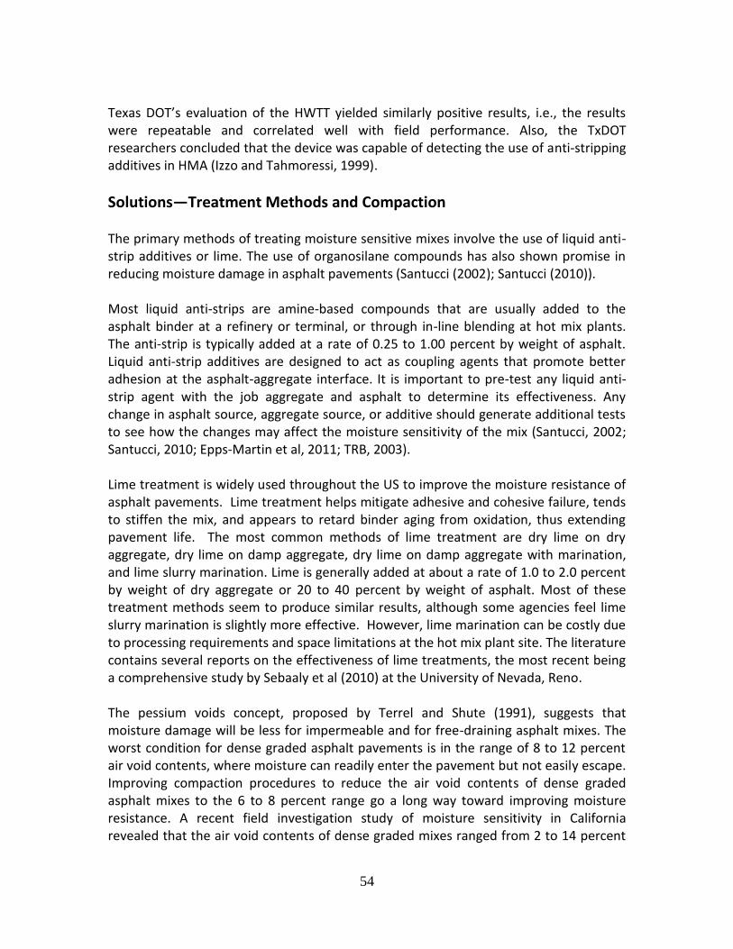
54
Texas DOT’s evaluation of the HWTT yielded similarly positive results, i.e., the results were repeatable and correlated well with field performance. Also, the TxDOT researchers concluded that the device was capable of detecting the use of anti-stripping additives in HMA (Izzo and Tahmoressi, 1999).
Solutions—Treatment Methods and Compaction The primary methods of treating moisture sensitive mixes involve the use of liquid anti-strip additives or lime. The use of organosilane compounds has also shown promise in reducing moisture damage in asphalt pavements (Santucci (2002); Santucci (2010)). Most liquid anti-strips are amine-based compounds that are usually added to the asphalt binder at a refinery or terminal, or through in-line blending at hot mix plants. The anti-strip is typically added at a rate of 0.25 to 1.00 percent by weight of asphalt. Liquid anti-strip additives are designed to act as coupling agents that promote better adhesion at the asphalt-aggregate interface. It is important to pre-test any liquid anti-strip agent with the job aggregate and asphalt to determine its effectiveness. Any change in asphalt source, aggregate source, or additive should generate additional tests to see how the changes may affect the moisture sensitivity of the mix (Santucci, 2002; Santucci, 2010; Epps-Martin et al, 2011; TRB, 2003). Lime treatment is widely used throughout the US to improve the moisture resistance of asphalt pavements. Lime treatment helps mitigate adhesive and cohesive failure, tends to stiffen the mix, and appears to retard binder aging from oxidation, thus extending pavement life. The most common methods of lime treatment are dry lime on dry aggregate, dry lime on damp aggregate, dry lime on damp aggregate with marination, and lime slurry marination. Lime is generally added at about a rate of 1.0 to 2.0 percent by weight of dry aggregate or 20 to 40 percent by weight of asphalt. Most of these treatment methods seem to produce similar results, although some agencies feel lime slurry marination is slightly more effective. However, lime marination can be costly due to processing requirements and space limitations at the hot mix plant site. The literature contains several reports on the effectiveness of lime treatments, the most recent being a comprehensive study by Sebaaly et al (2010) at the University of Nevada, Reno. The pessium voids concept, proposed by Terrel and Shute (1991), suggests that moisture damage will be less for impermeable and for free-draining asphalt mixes. The worst condition for dense graded asphalt pavements is in the range of 8 to 12 percent air void contents, where moisture can readily enter the pavement but not easily escape. Improving compaction procedures to reduce the air void contents of dense graded asphalt mixes to the 6 to 8 percent range go a long way toward improving moisture resistance. A recent field investigation study of moisture sensitivity in California revealed that the air void contents of dense graded mixes ranged from 2 to 14 percent

55
with a mean value of about 7 percent. Reducing the mean and especially the variance of these air void contents would help reduce the risk of moisture damage. Other research funded by Caltrans quantified the effect of air void content on fatigue resistance and stiffness (rut resistance) of dense graded mixes—first with laboratory tests and later verified with full scale Heavy Vehicle Simulator (HVS) tests on pavement sections. More recently, laboratory testing of Kentucky dense graded mixes revealed that a 1.5 percent reduction in air void content can increase mix fatigue life by 4 to 10 percent and increase rut resistance by 34 percent.
HMA Stripping--Recap Moisture damage in asphalt pavements is caused by adhesive failure between the asphalt film and aggregate or cohesive failure within the asphalt binder itself. Factors contributing to moisture-related distress include material properties such as type, shape, and porosity of the aggregate and viscosity, film thickness, and source of the asphalt binder. Hot mix plant production issues, including inadequately dried aggregate, can lead to moisture problems in the finished pavement. Construction practices that trap moisture in pavement layers, such as placing a high air void content mix between low air void content lifts or placing a chip seal over a moisture sensitive pavement, need to be avoided to minimize moisture damage. Treatment methods to minimize moisture damage involve the use of liquid anti-strip additives or lime. Liquid anti-strips are usually added to the asphalt at the refinery or through in-line blending at hot mix plants. Lime treatment methods include dry lime on dry aggregate, dry lime on damp aggregate, dry lime on damp aggregate with marination, or lime slurry marination. Good compaction procedures to reduce the air void content of dense graded asphalt pavements have been shown repeatedly to improve moisture resistance (≥ 93% of TMD). Slightly tightening existing requirements for maximum theoretical density will also improve the fatigue and rut resistance of asphalt pavements. Lower air void contents will tend to lower mix permeability and limit oxidative hardening of the asphalt binder, thus improving the long term durability of pavements.
Project Evaluation
The Basics In any HMA pavement construction project, the foundation must be able to support paving and compaction operations during construction. When using existing pavements, the “foundation” layer materials may include existing HMA intermediate/base course, existing concrete pavement (intact or fractured), or rubblized concrete. In the former
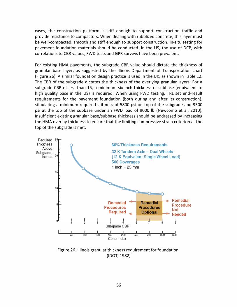
56
cases, the construction platform is stiff enough to support construction traffic and provide resistance to compactors. When dealing with rubblized concrete, this layer must be well-compacted, smooth and stiff enough to support construction. In-situ testing for pavement foundation materials should be conducted. In the US, the use of DCP, with correlations to CBR values, FWD tests and GPR surveys have been prevalent. For existing HMA pavements, the subgrade CBR value should dictate the thickness of granular base layer, as suggested by the Illinois Department of Transportation chart (Figure 26). A similar foundation design practice is used in the UK, as shown in Table 12. The CBR of the subgrade dictates the thickness of the overlying granular layers. For a subgrade CBR of less than 15, a minimum six-inch thickness of subbase (equivalent to high quality base in the US) is required. When using FWD testing, TRL set end-result requirements for the pavement foundation (both during and after its construction), stipulating a minimum required stiffness of 5800 psi on top of the subgrade and 9500 psi at the top of the subbase under an FWD load of 9000 lb (Newcomb et al, 2010). Insufficient existing granular base/subbase thickness should be addressed by increasing the HMA overlay thickness to ensure that the limiting compressive strain criterion at the top of the subgrade is met.
Figure 26. Illinois granular thickness requirement for foundation. (IDOT, 1982)
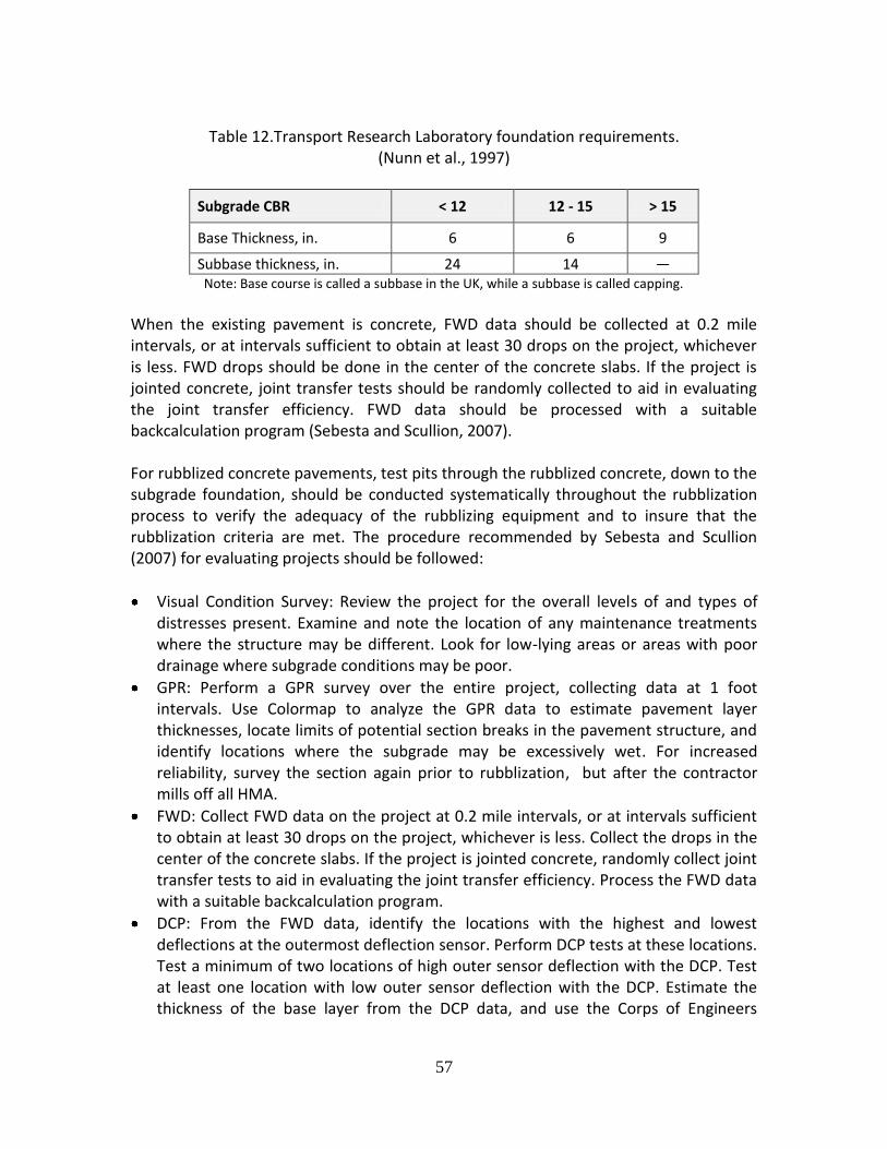
57
Table 12.Transport Research Laboratory foundation requirements.
(Nunn et al., 1997)
Subgrade CBR < 12 12 - 15 > 15
Base Thickness, in. 6 6 9
Subbase thickness, in. 24 14 — Note: Base course is called a subbase in the UK, while a subbase is called capping.
When the existing pavement is concrete, FWD data should be collected at 0.2 mile intervals, or at intervals sufficient to obtain at least 30 drops on the project, whichever is less. FWD drops should be done in the center of the concrete slabs. If the project is jointed concrete, joint transfer tests should be randomly collected to aid in evaluating the joint transfer efficiency. FWD data should be processed with a suitable backcalculation program (Sebesta and Scullion, 2007). For rubblized concrete pavements, test pits through the rubblized concrete, down to the subgrade foundation, should be conducted systematically throughout the rubblization process to verify the adequacy of the rubblizing equipment and to insure that the rubblization criteria are met. The procedure recommended by Sebesta and Scullion (2007) for evaluating projects should be followed:
Visual Condition Survey: Review the project for the overall levels of and types of distresses present. Examine and note the location of any maintenance treatments where the structure may be different. Look for low-lying areas or areas with poor drainage where subgrade conditions may be poor.
GPR: Perform a GPR survey over the entire project, collecting data at 1 foot intervals. Use Colormap to analyze the GPR data to estimate pavement layer thicknesses, locate limits of potential section breaks in the pavement structure, and identify locations where the subgrade may be excessively wet. For increased reliability, survey the section again prior to rubblization, but after the contractor mills off all HMA.
FWD: Collect FWD data on the project at 0.2 mile intervals, or at intervals sufficient to obtain at least 30 drops on the project, whichever is less. Collect the drops in the center of the concrete slabs. If the project is jointed concrete, randomly collect joint transfer tests to aid in evaluating the joint transfer efficiency. Process the FWD data with a suitable backcalculation program.
DCP: From the FWD data, identify the locations with the highest and lowest deflections at the outermost deflection sensor. Perform DCP tests at these locations. Test a minimum of two locations of high outer sensor deflection with the DCP. Test at least one location with low outer sensor deflection with the DCP. Estimate the thickness of the base layer from the DCP data, and use the Corps of Engineers

58
equation to convert the DCP penetration rate to CBR. Determine the CBR and thickness of the base layer. If the DCP data do not clearly detect a base layer, then use the CBR of the first 6 inches beneath the concrete as a “dummy” base layer (many older concrete pavements may not have a base beneath them). Determine the CBR of the first 6 inches of subgrade.
Top-Down Cracking It is critical that coring of the existing flexible pavement identify top-down cracking if it occurs in the existing pavement. The reasons for this are at least three: (1) there is a need to understand the origins of HMA cracking since that influences basic renewal decisions, (2) HMA quality control factors, such as density, can be impacted by this type of information, and (3) maintenance decisions for renewed pavements, such as crack sealing, will be influenced by such information. There are numerous studies worldwide that show this is a common cracking mode for HMA surfaces. The following may be broadly concluded:
Surface-initiated cracking of HMA is widespread, particularly for asphalt pavement layers with a combined thickness exceeding about 6 in. (although there have been reports of top-down cracking in thinner HMA). Further, this type of cracking has been reported for a variety of climate and traffic conditions, which are illustrated by Figures 27 to 30. Figure 27 shows top-down cracking in cores taken in Panama with significantly different core thicknesses. Figure 28 shows views of top-down cracking which occurred on both an Interstate highway and local streets in Washington State. Figure 29 shows longitudinal top-down cracking on a US Interstate highway and transverse and longitudinal top-down cracking in Panama (near Colon). Figure 30 shows two views of top-down cracking in Michigan including cracking over rubblized PCC pavement.
The age at which top-down surface cracking initiates ranges from 1 to 5 years following surface course construction (Japan, Matsuno and Nishizawa, 1992), 3 to 5 years (France, Dauzats and Rampal, 1987), 5 to 10 years (Florida, Myers et al, 1998), within 10 years (United Kingdom, Nunn, 1998), and 3 to 8 years with an average of 5 years (Washington State, Uhlmeyer et al, 2000). Generally, the HMA thicknesses associated with initiation of top-down cracking ranged from 6 to 7 in.
Surface cracks are caused by a combination of truck tires, thermal stresses, and age hardening of the binder. There is limited agreement on where the critical tensile stresses occur with the surface course. Most researchers note that the critical location is at or near the tire edge. Further, wide-base tires cause higher tensile stresses. Studies based on measured tire-pavement contact pressures and instrumented pavements support the view that truck tires are at least one cause of top-down cracking in HMA wearing courses.

59
HMA mix aging has a strong role in top-down cracking. Rolt (2001) reported that top-down cracking is widely observed in tropical environments and appears to be related to the age hardening of the asphalt binder in the upper 2 to 3 mm of surface courses. It was found that the binder is typically 100 to 500 times more viscous in that 2 to 3 mm zone, hence more brittle, than the binder at a depth of about 10 to 25 mm following initial aging (some of the results reported by Rolt noted a field aging period of 24 months). Importantly, Rolt noted that the increase in binder viscosity was strongly related to age, but HMA mix variables such as air voids, binder content, and filler content were positive second order factors. An additional finding was that application of a surface dressing (such as a chip seal) to the HMA pavement surface soon after construction was observed to reduce binder aging by a factor of about 50.
Observations made by Rolt (2001) and Uhlmeyer (200) note that top-down cracking, once initiated, remains at a constant depth for some time before eventually propagating to the full depth of the HMA layer(s).
Figure 27. Top down cracking in cores from Panama. (core thicknesses ranged from 6 to 12 in. thick)

60
Figure 28. Illustrations of top-down cracking in Washington State. (the upper photos are from Interstate 90; the bottom photos local streets in western
Washington)
Figure 29. Illustration of longitudinal top-down cracking following crack sealing for a US Interstate Highway (left) and longitudinal and transverse top-down cracking in Panama
(right).

61
Figure 30. Two views of longitudinal top-down cracking in Michigan. (the photo on the right is HMA placed over rubblized PCC pavement)
HMA Construction Quality Control Construction of a long life pavement should not be much different than conventional pavements, other than requiring a heightened attention to detail and a commitment to build it with quality from the bottom up. Testing should be employed to give continuous feedback on the quality of materials and construction. Achieving uniformity is crucial for ensuring long life. Along with a proper structural design and mix type, good construction practices are needed to ensure good performance. HMA construction issues that can be detrimental to performance include lack of density, permeability to water, lack of interface bonding, and segregation. These issues are discussed below.
HMA Density The density of the asphalt base layer can be affected by its interlayer friction with the pavement foundation. Insufficient friction between these two layers will lead to problems in compacting the base layer as it will tend to shove out from under the rollers. This condition can occur if there is excessive dust on the foundation surface or if it has recently rained. Remedial action for such a condition may include waiting for the material to become drier, excavating the top few inches of the foundation to remove the dust, adding granular material to the top of the foundation, or using a thicker lift for the bottom of the base course. An extreme measure would be to place a chip seal on the foundation to provide the necessary friction to hold the asphalt mix in place during compaction. Another primary issue affecting HMA density in the field is lift thickness. One needs to make sure that the lift thickness corresponds appropriately to the nominal maximum

62
aggregate size in the mixture as provided by Newcomb and Hansen (2006) in Table 8. In general, the lift thickness should be three to four times the NMAS for fine-graded mixtures and four to five times for coarse-graded mixtures (Brown et al., 2004). The lack of density in the asphalt layers may also be caused by stiff mixes (e.g., mixes with overly oxidized binders due to overheating in the mixing process, and mixes with polymer modified asphalt binders) that are difficult to work and compact. Industry guidelines provided by APEC (2001) may be used to ensure the proper temperature is used in the handling and application of liquid asphalt binders. The workability of asphalt mixtures may be improved with Warm Mix Asphalt technologies which allow the material to be placed and compacted at temperatures anywhere from 35 to 100oF lower than conventional asphalt mixtures (Prowell and Hurley, 2007). Prowell and Brown (2007), in NCHRP Report 573, noted that in-place field densities between 92 percent and 97 percent of maximum theoretical density (i.e., 3 to 8 percent air voids) for surface courses will generally provide good performance (based on mixes with gradations passing through or above the Superpave-defined restricted zone). Further, when HMA is placed has an effect on density. Prowell and Brown showed that the majority of the densification of HMA occurs in the first three months following construction. This is somewhat counter to prior views that held most of the post-construction densification occurs within two years. Further, for HMA placed during cooler fall months, the rapid, additional densification may not occur in time for winter weather. State DOTs have a range of HMA density specifications. Many of these types of specifications are statistically based with some form of lower specification limit. Based on a survey done in 2001 of several western states and Federal Lands (Mahoney and Economy, 2001), the reported average in-place HMA density ranged between 92 and 93 percent of TMD. The lower specification density requirement ranged between 91 and 92 percent. Given the evidence available, it is suggested that an average density value for dense-graded mixes ≥ 93 percent of TMD.
HMA Segregation Segregation can be caused by a separation of fine and coarse aggregates during production, transport, and placement (AASHTO, 1997), or by temperature differentials that occur during transport and paving operations (Willoughby et al., 2002). Coarse aggregate mixtures are usually the most problematic. The danger with segregation in large aggregate, coarsely graded mixtures is that the mix may become permeable in coarse pockets, which could lead to the infiltration of water and subsequent moisture damage (Scullion, 2006). Segregation may be measured with infrared temperature techniques and laser texture methods such as the Rosan procedure (Stroup-Gardiner

63
and Brown, 2000). Figure 31 illustrates both the open texture resulting from temperature differentials on a two lane state highway and an infrared image that shows the cooler mix (green and yellow), which leads to lower as-compacted mix densities.
Figure 31. HMA segregation caused by temperature differentials. Segregation can be addressed by proper handling of the material during manufacture, transport, and laydown. The use of material transfer devices that remix the HMA prior to placement can help in avoiding thermal segregation. Also, the selection of the appropriate mix design can help in avoiding many of the problems associated with segregation. For example, one should design large stone asphalt base mixtures to a lower void content so that it is less susceptible to being permeable. Alternatively, one can choose a mix with finer total gradation, which will lessen the possibility of segregation. To insure impermeability, one can use a fine surface mix, which will seal the surface of the pavement preventing moisture infiltration from the top. If temperature differentials occur during construction, but the finished pavement has a uniform density of 93 percent of TMD or greater for traditional dense-graded mixes, then the pavement should serve its intended length of time. Given the types of pavement distress that result from temperature differentials, it is common to see pavement surfaces that would otherwise last about 12 years require repaving in 7 to 8 years (or less). This translates to a 30 to 40 percent reduction in pavement surface life. Extreme cases have occurred where the reduction in pavement life is far higher. The lower densities are rarely uniform, but group in systematic or cyclic areas as shown in Figure 26. Temperature variations of 50 to 100°F or more have been observed following laydown. A rule-of-thumb is that for every 25°F difference (or decrease) in mat temperature, the air voids in the compacted mix are reduced by 1 percent (Willoughby et al, 2001).

64
A number of HMA specification modifications have been crafted largely by State DOTs to address non-uniform laydown temperatures and mix densities. One technique requires that density profiles be taken. That process provides a method of determining the effect of the temperature differentials in the finished product. It can locate potential areas of low density, test those areas, and provide results (via nuclear asphalt content gauge) to determine the extent of the problem. The technique gets the job done; however, the testing is time consuming and results a large number of tests. What is clear is that typical random sampling associated with HMA density testing does not and should not be expected to identify non-uniform conditions. A relatively new solution is to measure whether temperature variation is a major factor on a paving project by 100 percent sampling of the freshly laid HMA mat. The Pave-IR system (MOBA Corp) provides this type of sampling along with providing a permanent, continuous record of paver operations. Locations for testing can be quickly selected at critical locations to measure the severity of the problem. The device attaches to the paver screen as shown in Figure 32.
Figure 32. Pave-IR Thermal Imaging System. (Photos: Study Team)
Longitudinal Joints Longitudinal joints are potential weakness areas in HMA pavement construction because density tends to be lower at the edges of the asphalt mat, and the mix may be more permeable at this point, and more susceptible to moisture infiltration and damage. Guidance exists on the best way to construct longitudinal joints (NAPA, 2002). The use of echelon paving or full-width paving has the effect of essentially eliminating the longitudinal joint, since the two paving lanes are placed at the same time. This should be considered as the best solution, although it may not always be possible to implement due to space limitations. Other ways to improve longitudinal joint performance include using techniques such as wedge joints, joint heaters, and joint sealants (Brown, 2006). Also, joints should be staggered between lifts to break any

65
continuity in potentially weak joints. Finally, one of the most practical ways of protecting longitudinal joints in lower pavement layers is to use a fine-graded, impermeable mixture on the pavement surface, which will effectively seal the joint in addition to providing a quiet, smooth surface.
Interlayer Bonding Bonding between asphalt layers is critical to long-term performance, since the total HMA layer would only act as one layer if full bonding between interlayers exists. Otherwise, these thinner layers will behave independently (they will slip relative to each other), thus leading to significantly higher tensile strains, which will cause premature cracking. This was demonstrated at the NCAT test track (Willis and Timm, 2007). Before applying any tack or bond coat, the previous layer should be clean and dust-free in order to ensure good adhesion. Once the tack coat is applied, precautions should be taken to ensure that the coat remains clean until the next layer is placed. This means limiting the time between the application of the tack coat and laying the next layer, and preventing any construction traffic other than that for laying the HMA. It has also been shown that milling enhances the bond in the case of asphalt overlays (West et al., 2005). Therefore, milling should be encouraged not only to remove surface defects but also to ensure the bonding of the overlay to the existing pavement surface.
QC Testing Quality volumetric control of the mixtures is essential to ensure consistency and quality in the final product. The contractor should have access to a fully equipped and staffed quality control laboratory, and should conduct periodic testing and data analysis with good quality control and inspection techniques. In-place density can be checked using either nuclear or dielectric methods of testing; ground penetrating radar can be used as a continuous monitoring tool to check thickness; and smoothness can be evaluated with new lightweight profilometers.
HMA Quality Control and Specifications Examples of guide specification elements are shown in Table 13 that are relevant for HMA quality control. The table includes a brief explanation why the issue is of special interest along with examples from the study guide specification recommendations. These specification elements are sorted by (1) HMA density, (2) HMA segregation, (3) longitudinal joints, and (4) interlayer bonding.
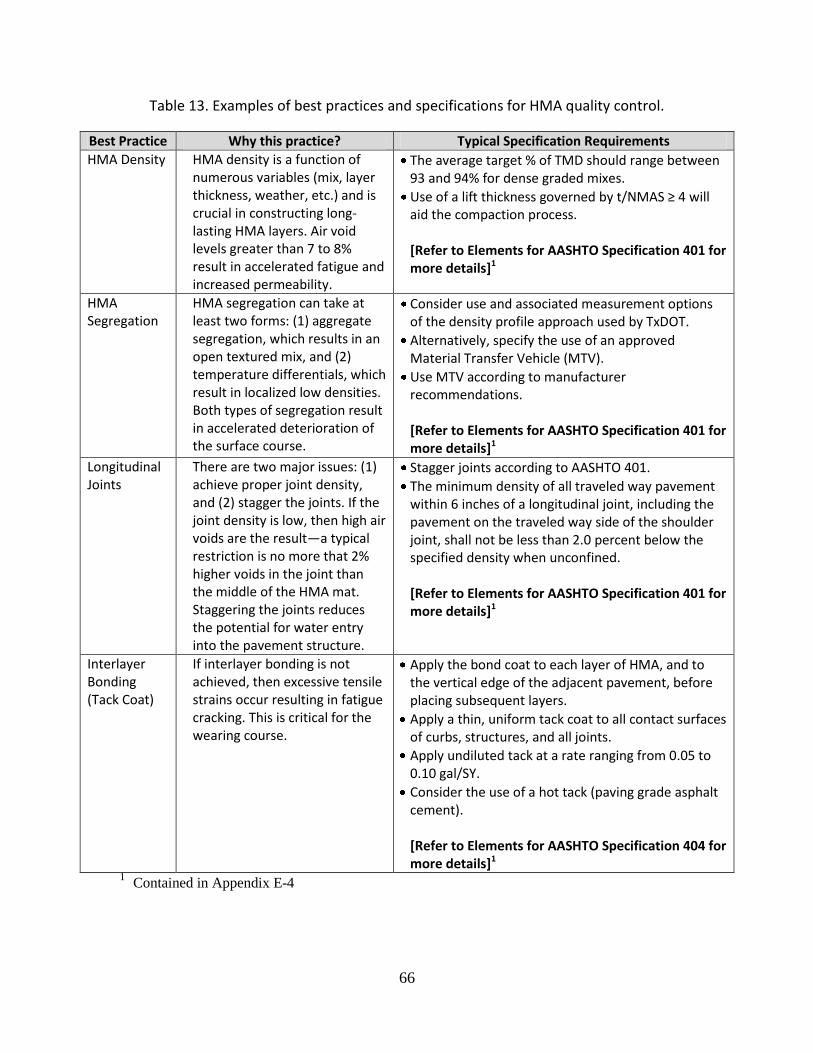
66
Table 13. Examples of best practices and specifications for HMA quality control.
Best Practice Why this practice? Typical Specification Requirements
HMA Density HMA density is a function of numerous variables (mix, layer thickness, weather, etc.) and is crucial in constructing long-lasting HMA layers. Air void levels greater than 7 to 8% result in accelerated fatigue and increased permeability.
The average target % of TMD should range between 93 and 94% for dense graded mixes.
Use of a lift thickness governed by t/NMAS ≥ 4 will aid the compaction process. [Refer to Elements for AASHTO Specification 401 for more details]1
HMA Segregation
HMA segregation can take at least two forms: (1) aggregate segregation, which results in an open textured mix, and (2) temperature differentials, which result in localized low densities. Both types of segregation result in accelerated deterioration of the surface course.
Consider use and associated measurement options of the density profile approach used by TxDOT.
Alternatively, specify the use of an approved Material Transfer Vehicle (MTV).
Use MTV according to manufacturer recommendations. [Refer to Elements for AASHTO Specification 401 for more details]1
Longitudinal Joints
There are two major issues: (1) achieve proper joint density, and (2) stagger the joints. If the joint density is low, then high air voids are the result—a typical restriction is no more that 2% higher voids in the joint than the middle of the HMA mat. Staggering the joints reduces the potential for water entry into the pavement structure.
Stagger joints according to AASHTO 401.
The minimum density of all traveled way pavement within 6 inches of a longitudinal joint, including the pavement on the traveled way side of the shoulder joint, shall not be less than 2.0 percent below the specified density when unconfined. [Refer to Elements for AASHTO Specification 401 for more details]1
Interlayer Bonding (Tack Coat)
If interlayer bonding is not achieved, then excessive tensile strains occur resulting in fatigue cracking. This is critical for the wearing course.
Apply the bond coat to each layer of HMA, and to the vertical edge of the adjacent pavement, before placing subsequent layers.
Apply a thin, uniform tack coat to all contact surfaces of curbs, structures, and all joints.
Apply undiluted tack at a rate ranging from 0.05 to 0.10 gal/SY.
Consider the use of a hot tack (paving grade asphalt cement). [Refer to Elements for AASHTO Specification 404 for more details]1
1 Contained in Appendix E-4

67
Summary A summary of the flexible pavement best practices is provided in Table 14. They are grouped by:
Structural design
HMA mix design
HMA construction, and
Process of existing PCCP layers.

68
Table 14. Summary of flexible pavement best practices for long-lasting pavements.
Best Practice Category Typical Requirements
Structural Design 1. Long-lasting flexible pavement renewal options will be thick. Generally additional HMA thicknesses ≥ 6.0 in. are required. a. Minimum thickness of HMA over crack and seat PCCP is 6.0 in. b. Minimum thickness of HMA over rubblized PCCP is 8.0 in. c. HMA thicknesses over existing CRCP are typically ≥ 4.0 in.
2. Design tools such as PerRoad or the MEPDG are needed for detailed design analyses. Use the endurance limit concept for HMA thickness design.
3. Before selecting the option of PCCP rubblization, check the suitability for rubblization by use of the TxDOT criteria (PCCP thickness vs. CBR). If the upper 12 in. of the subgrade has a CBR ≥ 7, risk associated with this process is significantly reduced.
Mix Selection and Design
1. Modified PG binders have been shown to significantly reduce rutting. However, the stiffer the binder, the more difficult the placement and compaction. Refer to LTPPBind for advice as to specific PG grades to use.
2. Consider use of fine graded HMA mix. Dense HMA mixes with a fine gradation have been shown to perform as well as or better than dense coarse graded mixes.
3. Consider use of SMA for wearing courses. They exhibit superior performance for both cracking and rutting.
4. Smaller NMAS mixes (≤ 12.5 mm) are better choices. This is broadly true for both SMA and dense graded HMA mixes.
HMA Construction 1. HMA average field density should be ≥ 93% of TMD for dense graded HMA. Higher densities reduce the rate of surface aging in the wearing course.
2. Should use lift thicknesses (defined by t/NMAS) ≥ 4 and must use t/NMAS ≥ 3.
3. HMA segregation must be prevented. This is best done with a MTV. Alternatively, an aggressive testing program with infrared imaging will readily reveal potential problems during paving operations.
4. The density of longitudinal joints must be specified and be similar to that required of the overall mat (but not necessarily the same).
5. Stagger longitudinal joints in multiple HMA lifts. Exceptions can be made for crown lines.
6. Place a uniform tack coat between all HMA layers. No exceptions.
Processing of Existing PCC Layers
1. Crack and seated PCCP is preferred over rubblization, if possible. 2. A wide range of crack spacings have been suggested for crack and seated
PCCP. Dimensions up to 5 ft. by 6 ft. have worked well. 3. Jointed reinforced concrete pavement must receive a saw, crack and
seat treatment. The crack spacing is about the same as for crack and seat. The saw cut must sever the existing reinforcing steel.
4. The depth of cracks must be checked by coring. 5. The particle sizes for rubblized PCCP must be specified and checked.

69
References
Ahlrich, R. C., 1989, “Performance and Structural Evaluation of Cracked and Seated Concrete,” Transportation Research Record No. 1215, Transportation Research Board, National Research Council, Washington, DC. AASHTO, 1993, “AASHTO Guide for Design of Pavement Structures,” American Association of State Highway and Transportation Officials, Washington, DC. AASHTO, 1997, “Segregation: Causes and Cures for Hot Mix Asphalt,” American Association of State Highway and Transportation Officials, Washington, DC. AASHTO, 2008a,”Guide Specifications for Highway Construction,” American Association of State Highway and Transportation Officials, Washington, DC. AASHTO, 2008b, “Mechanistic-Empirical Pavement Design Guide,” Interim Edition: A Manual of Practice, American Association of State Highway and Transportation Officials, Washington, DC. Aschenbrener, T., 1995, “Evaluation of Hamburg Wheel-Tracking Device to Predict Moisture Damage in Hot Mix Asphalt,” Transportation Research Record 1492, Transportation Research Board, National Research Council. Aschenbrener, T., R.B. McGennis, and R.L. Terrel, 1995, “Comparison of Several Moisture Susceptibility Tests to Pavements of Known Field Performance,” Journal of the Association of Asphalt Paving Technologists, Vol. 64. Applied Research Associates, Inc., 2004, “Guide for Mechanistic-Empirical Design of New and Rehabilitated Pavement Structures,” Final Report, NCHRP Project 1-37A, National Cooperative Highway Research Program, Transportation Research Board, National Research Council, Washington, DC. Asphalt Institute (AI), 1982, “Thickness Design, Asphalt Pavements for Highways and Streets,” Report MS-1. Lexington, Kentucky. Asphalt Institute, 1996a, “Performance Graded Asphalt,” SP-1. Lexington, Kentucky. Asphalt Institute, 1996b, “Superpave Mix Design,” SP-2. Lexington, Kentucky. Asphalt Pavement Alliance, 2002, “Perpetual Pavements: A Synthesis”, APA 101, Lanham, MD.

70
Asphalt Pavement Environmental Council (APEC), 2001, “Best Management Practices to Minimize Emissions During HMA Construction.” Report No. EC-101. Lanham, Maryland. Baker, M.J. and J.P. Mahoney, 2000, “Identification and Assessment of Washington State Pavements with Superior and Inferior Performance,” Report No. WA-RD 437.1. Washington State Department of Transportation. Olympia. Baladi, G. Y., M. G. Niederquell and K. Chatti, 2000, “Identify Causes for Under Performing Rubblized Concrete Pavement Projects,” Report No. MDOT-PRCE-MSU-1999 -110, Michigan Department of Transportation. Lansing, MI. Bang, S., L. Roberts, D. Huft, D. Johnston, P. Sebaaly, 2010, “Quality Base Material Produced Using FDR,” Presented by L. Roberts at the AEMA-ARRA-ISSA Annual Meeting: Preservation & Rehabilitation 2010 –Roads to Recovery; March 2-5, 2010. Blankenship, Phillip, 2009, “How Much Does Density Matter?” Asphalt Magazine, Vol. 24, No. 3, Asphalt Institute, Fall 2009. Brown, E.R. and L.A. Cooley, 1999, “Designing Stone Matrix Asphalt Mixtures for Rut-Resistant Pavements,” Report No. 425. National Cooperative Highway Research Program, Transportation Research Board. Washington, DC. Brown, E.R., P.S. Kandhal, and J. Zhang, 2001, “Performance Testing for Hot Mix Asphalt,” Report No. 2001-05. National Center for Asphalt Technology, Auburn University, Alabama. Brown, E.R., M.R. Hainin, A. Cooley, and G. Hurley, 2004, “Relationship of Air Voids, Lift Thickness, and Permeability in Hot Mix Asphalt Pavements,” Report No. 531. National Cooperative Highway Research Program. Transportation Research Board. Washington, DC, September 2004. Brown, E.R., 2006, “Basics of Longitudinal Joint Construction,” Circular EC-105. Factors Affecting Compaction of Asphalt Pavements. Transportation Research Board, Washington, DC. pp. 86-95. Buncher, M., Fitts, G., Scullion, T., McQueen, R., 2008, “Development of Guidelines for Rubblization,” Final Report, Airfield Asphalt Pavement Technology Program Project 04-01, Asphalt Institute, May 23, 2008. Bushmeyer, B., 2002, “The Quest for Long-Life Asphalt Pavement,” Better Roads. February 2002. Caltrans, 2004, “Interim PCC Pavement Rehabilitation Guidelines,” Pavement Tech Notes, California Department of Transportation, July 28, 2004.
71
Caltrans, 2008, “Crack Existing Concrete Pavement,” Standard Special Provision #41-250, California Department of Transportation, October 24, 2008. Coley, C. C., and Carswell, I., 2006, "Improved design of overlay treatments to concrete pavements. Final report on the monitoring of trials and schemes," TRL Report TRL657, TRL. Limited, Wokingham. Cooley, L., and Brown, R., 2003, “Potential of Using Stone Matrix Asphalt (SMA) for Thin Overlays,” NCAT Report 03-01, National Center for Asphalt Technology, Auburn, University, Alabama, April 2003. Cross, S., 2012, “Cold In-Place Recycling (CIR) Study,” Publication No. FHWA-CFL/TD-12-00x, Central Federal Lands Highway Division, FHWA, September 2012. Decker, D., 2006, Rubblization, IS-132. National Asphalt Pavement Assn. Lanham, Maryland. Department for Transport, 2010, “Manual of Contract Documents for Highway Works,” Volume 1, Series 0700, Road Pavement General, Highways Agency, Department of Transport, UK. Dauzats, M., and Rampal, A., 1987, “Mechanism of Surface Cracking in Wearing Courses,” Proc., 6th International Conference on Structural Design of Asphalt Pavements, University of Michigan, Ann Arbor, pp. 232–247. Epps, J.A. and C.L. Monismith, 1972, “Fatigue of Asphalt Concrete Mixtures – Summary of Existing Information,” STP 508, American Society of Testing and Materials. Conshohocken, PA. pp. 3-18. Epps-Martin, A., E. Arambula, C. Estakhri, J. Epps, E. Park, F. Yin, L, Walubita, R. Lytton, 2011, “Performance of WMA Technologies: Stage I – Moisture Susceptibility,” Phase I Interim Report, NCHRP 09-49, March 2011. European Asphalt Pavement Association, 2007, “EAPA Report on Long-Life Asphalt Pavements - Technical version,” EAPA, Brussels. European Asphalt Pavement Association, 2009. “High Modulus Asphalt,” Publication (99)2-098-05001, EAPA, Brussels. FHWA, 1997, “Pavement Recycling Guidelines for State and Local Governments: Participant's Reference Book,” Publication No. FHWA-SA-98-042.

72
Fee, F., 2001, “Extended-Life Asphalt Pavement: new approaches to increase durability,” TR News. No. 215. Transportation Research Board. Washington, DC. p.12. July-August 2001. Ferne, B. and M. Nunn., 2004, “The European Approach to Long Lasting Asphalt Pavements–A State-of-the-Art Review by European Long-Life Pavements Group (ELLPAG),” Proceedings, International Symposium on Design and Construction of Long Lasting Asphalt Pavements, National Center for Asphalt Technology, Auburn University, Alabama. pp. 87-102. Ferne, B., 2006, “Long-life Pavements-a European Study by ELLPAG,” Intl. Jn. of Pavement Engineering, Vol. 7 No.2, Taylor and Francis Ltd. New York. pp. 91-100. Fitts, G. L., 2006, “Rubblization Using Resonant Frequency Equipment”, Transportation Research Circular E-C087, Transportation Research Board, Washington, DC. Hall, K. T., C. E. Correa, S. H. Carpenter, and R. P. Elliott, 2001, “Guide for Selection of Pavement Rehabilitation Strategies,” Final Report, NCHRP Project 1-38, National Cooperative Highway Research Program, Transportation Research Board, National Research Council, Washington, DC. Harvey, J.T., J.A. Deacon, B-W Tsai, and C.L. Monismith, 1996, “Fatigue Performance of Asphalt Concrete Mixes and Its Relationship to Asphalt Concrete Performance in California,” Report No. RTA-65W485-2, Pavement Research Center, CAL/APT Program, Institute of Transportation Studies, University of California, Berkeley, January 1996. Harvey, J., Carl Monismith, M. Bejarano, B.W. Tsai, and V. Kannekanti, 2004, “Long-Life AC Pavements: A Discussion of Design and Construction Criteria based on California Experience,” Proceedings, Intl. Symp. on Design and Construction of Long Lasting Asphalt Pavements. National Center for Asphalt Technology, Auburn University, Alabama, pp. 285-334. Hicks, R.G., L. Santucci, and T. Aschenbrener, 2003, “Introduction and Seminar Objectives, Topic 1,” National Seminar on Moisture Sensitivity of Asphalt Pavements, TRB Miscellaneous Report ISBN 0-309-09450-X, February 4-6, 2003. Hot-Mix Magazine, 2010, “Cold In-Place Recycling (CIR),” Volume 14, Number 2, Astec, Chattanooga, TN. http://www.hotmixmag.com Huber, G., 2000, “Performance Survey on Open-Graded Friction Course Mixes,” NCHRP Synthesis 284, Transportation Research Board, Washington, DC. Illinois Department of Transportation (IDOT), 1982, “Subgrade Stability Manual,” Policy MAT-10, Springfield.

73
Illinois Department of Transportation (IDOT), 2002, “Standard Specifications for Road and Bridge Construction,” Illinois Department of Transportation, Springfield. Izzo, R. and M Tahmoressi, 1999, “Use of the Hamburg Wheel-Tracking Device for Evaluating Moisture Susceptibility of Hot Mix Asphalt,” Transportation Research Record 1681, Transportation Research Board, Washington, DC. Jordan, R.W., C. Coley, H.M. Harding, I. Carswell and K.E. Hassan, 2008, “Best Practice Guide for Overlaying Concrete,” TRL Road Note RN41, Transportation Research Laboratory, Crowthorne House, United Kingdom. Kandhal, P.S., 1990, “Design of Large-Stone Mixes to Minimize Rutting,” Transportation Research Record No. 1259, Transportation Research Board, Washington, DC. Kandhal, P.S. and R.B. Mallick., 1999, “Design of New-Generation Open-Graded Friction Courses,” Report No. 99-3. National Center for Asphalt Technology, Auburn University, Alabama. Kandhal, P.S., 2001, “Design, Construction, and Maintenance of Open-Graded Asphalt Friction Courses,” Quality Improvement Series IS-115, National Asphalt Pavement Association, Lanham, Maryland. Kentucky Transportation Cabinet (KTC), 2007, “Pavement Design Guide (2007 Revision) for Projects off the National Highway System less than 20,000,000 ESALs, less than 15,000 AADT, and less than 20% trucks,” Kentucky Transportation Cabinet Division of Highway Design. Lexington, KY. Kiggundu, B.M., and F.L. Roberts, 1988, “Stripping in HMA Mixtures: State-of-the-Art and Critical Review of Test Methods,” NCAT Report No. 88-2, National Center for Asphalt Technology, Auburn, AL. Linden, R.N., J.P. Mahoney, and N.C. Jackson, 1989, “Effect of Compaction on Asphalt Concrete Performance,” Transportation Research Record 1217, Transportation Research Board, Washington, DC. Long Term Pavement Performance (LTPP), 2010, LTPP DataPave Products On-line, Date accessed: January 29, 2010. Mahboub, K. and E.G. Williams, 1990, “Construction of Large-Stone Mixes (LSAM) in Kentucky,” Transportation Research Record No. 1282, Transportation Research Board, Washington, DC.

74
Mahoney, J.P., 2001, “Study of Long-Lasting Pavements in Washington State,” Transportation Research Circular Number 503, Perpetual Bituminous Pavements. pp. 88-95. Mahoney, J. and Economy, L, 2001, “Results of the PCCAS Questionnaire on State Highway and Federal Agency Quality Control/Quality Assurance Programs for Asphalt Concrete,” Report to the Pacific Coast Conference on Asphalt Specifications, Reno, Nevada, September 2001. Mahoney, J.P., C.L. Monismith, J. Coplantz, J. Harvey, V. Kannekanti, L. Pierce, J. Uhlmeyer, N. Sivaneswaran, and T. Hoover, 2007, “Pavement Lessons Learned from the 50-Year-Old Interstate Highway System: California, Oregon, and Washington,” E-Circular No. 118. Transportation Research Board. Washington, DC. pp. 88-103. Mallick, R., Cooley, L., Teto, M., Badbury, R., and Peabody, D., 2003, “An Evaluation of Factors Affecting Permeability of Superpave Designed Pavements,” NCAT Report 03-02, National Center for Asphalt Technology, Auburn University, Alabama, June 2003. Mamlouk, M.S. and Zaniewski, J.P. (2011), “Materials for Civil and Construction Engineers,” Third Edition, Prentice Hall. Matsuno, S., and Nishizawa, T., 1992, “Mechanisms of Surface-Initiated Longitudinal Wheel Path Cracks in High-Type Bituminous Pavements,” Proc., 7th International Conference on Asphalt Pavements, Vol. 2, University of Nottingham, pp. 277–291. Merrill, D., 2005, “Guidance on the Development, Assessment and Maintenance of Long-life Flexible Pavements,” TRL Report TRL639; prepared for Highways Agency, Quarry Products Association, and Refined Bitumen Association. Merrill, D., A. Van Dommelen and L. Gaspar, 2006, “A Review of Practical Experience Throughout Europe on Deterioration in Fully-Flexible and Semi-Rigid Long-Life Pavements,” Int. Jn. of Pavement Engineering, Vol. 7 No. 2. Taylor and Francis Ltd. New York. pp. 101-109. Michael, L., Burke, G., and Schwartz, C.W. (2005), “Performance of Stone Mastrix Asphalt Pavements in Maryland,” Conference Paper, www.camineros.com/docs/cam017.pdf Miner, M.A., 1959, “Estimation of Fatigue Life with Emphasis on Cumulative Damage,” Metal Fatigue, edited by Sines and Wiseman, McGraw Hill, pp. 278-89.

75
Monismith, C.L., 1992, “Analytically Based Asphalt Pavement Design and Rehabilitation: Theory in Practice,” 1962-1992. Transp. Res. Rec. No. 1354. Transportation Research Board. Washington, D.C., pp. 5-26. Monismith, C.L. and F. Long, 1999a, “Mix Design and Analysis and Structural Section Design for Full Depth Pavement for Interstate Route 710,” Technical Memorandum TM UCB PRC 99-2, Pavement Research Center, Institute for Transportation Studies, University of California, Berkeley. Monismith, C.L. and F. Long, 1999b, “Overlay Design for Cracked and Seated Portland Cement Concrete (PCC) Pavement – Interstate Route 710,” Technical Memorandum TM UCB PRC 99-3, Pavement Research Center, Institute for Transportation Studies, University of California, Berkeley. Monismith, C.L., J.T. Harvey, T. Bressette, C. Suszko, and J. St. Martin, 2009a, “The Phase One I-710 Rehabilitation Project: Initial Design (1999) to Performance after Five Years of Traffic,” Proceedings, International Conference on Perpetual Pavements, Ohio University, Columbus. CD-ROM. Monismith, C., Harvey, J., Tsai, B., Long, F., and Signore, J., 2009b, “Summary Report: The Phase One I-710 Freeway Rehabilitation Project: Initial Design (1999) to Performance after Five-Plus Years of Traffic,” UCPRC-SR-2008-04, Pavement Research Center, University of California, February 2009. Muench, S.T., G.C. White, J.P. Mahoney, L.M. Pierce, N. Sivaneswaran, 2004, “Long-Lasting Low-Volume Pavements in Washington State,” Proceedings, Intl. Symp. on Design and Construction of Long Lasting Asphalt Pavements, National Center for Asphalt Technology, Auburn University, Alabama. pp. 729-773. Myers, L. A., Roque, R. and Ruth, B.E., 1998, “Mechanisms of Surface-Initiated Longitudinal Wheel Path Cracks in High-Type Bituminous Pavements,” Proceedings, Vol. 67, Association of Asphalt Paving Technologists. National Asphalt Pavement Association (NAPA), 1994, “Guidelines for the Use of HMA Overlays to Rehabilitate PCC Pavements,” Information Series 117. National Asphalt Pavement Association (NAPA), 2002, “Longitudinal Joints: Problems and Solutions,” QIS 121. Lanham, Maryland. Newcomb, D., M. Buncher, and I.J. Huddleston, 2000, “Concepts of Perpetual Pavements” Transportation Research Circular No. 503, Perpetual Bituminous Pavements, Transportation Research Board. Washington, DC. pp. 4-11.

76
Newcomb, D. and K.R. Hansen, 2006, “Mix Type Selection for Perpetual Pavements,” Proceedings, International Conference on Perpetual Pavements, Ohio University, Columbus. CD-ROM. Newcomb, D., 2009, “Thin Asphalt Overlays for Pavement Preservation,” Information Series 135, National Asphalt Pavement Association, Lanham, MD. Newcomb D., R. Willis, D. Timm, 2010, “Perpetual Asphalt Pavements: A Synthesis,” Asphalt Pavement Alliance IM-40. Nishizawa, T., S. Shimeno, and M. Sekiguchi, 1996, “Fatigue Analysis of Asphalt Pavements with Thick Asphalt Mixture Layers,” Proceedings, 8th International Conference on Asphalt Pavements, Seattle, Washington. pp. 969-976. Nunn, M.E., A. Brown, D. Weston and J.C. Nicholls, 1997, “Design of Long-Life Flexible Pavements for Heavy Traffic,” Report No. 250, Transportation Research Laboratory, Berkshire, United Kingdom. Nunn, M., 1998, “Design of Long-Life Roads for Heavy Traffic,” Proc., Industry Conference, Australian Asphalt Pavement Association, Queensland, Australia. Nunn, M. and B.W. Ferne, 2001, “Design and Assessment of Long-Life Flexible Pavements,” Transportation Research Circular Number 503, Transportation Research Board. Washington, DC. pp 32-49. Ovik, J., B. Birgisson, and D.E. Newcomb, 1999, “Characterizing Seasonal Variations in Flexible Pavement Material Properties,” Transportation Research Record 1684, Transportation Research Board, Washington, DC. Pavement Interactive, 2011, “Laboratory Wheel Tracking Devices,” University of Washington. Peterson, R.L. P. Turner, M. Anderson, and M. Buncher, 2004, “Determination of Threshold Strain Level for Fatigue Endurance Limit in Asphalt Mixtures,” Proceedings, International Symposium on Design and Construction of Long Lasting Asphalt Pavements, National Center for Asphalt Technology, Auburn University, Alabama. pp. 385-410. Pierce, L.M. and J.P. Mahoney, 1996, “Asphalt Concrete Overlay Design Case Studies,” Transportation Research Record 1543. Transportation Research Board. Washington, DC.

77
Priest, A.L., 2006, “Methodology and Calibration of Fatigue Transfer Functions for Mechanistic-Empirical Flexible Pavement Design,” NCAT Report 06-03, National Center for Asphalt Technology, Auburn University, Alabama. Prowell, B.D. and E.R. Brown, 2006, “Methods for Determining the Endurance Limit Using Beam Fatigue Tests,” Proceedings, International Conference on Perpetual Pavements, Ohio University, Columbus. CD-ROM. Prowell, B. and Brown, R., 2007, “Superpave Mix Design: Verifying Gyration Levels in the Ndesign Table, Report 573, National Cooperative Highway Research Program, Transportation Research Board, Washington, DC. Prowell, B. D. and G.C. Hurley, 2007, “Warm-Mix Asphalt: Best Practices,” QIS-125, National Asphalt Pavement Association, Lanham, Maryland. Qing, Lu, J.T. Harvey, and C.L. Monismith, 2007, “Investigation of Conditions for Moisture Damage in Asphalt Concrete and Appropriate Laboratory Test Methods: Summary Version,” Draft Research Report: UCPRC-SR-2005-01, University of California Pavement Research Center, August 2007. Rahim, A. and Fiegel, G., 2011, “An Evaluation of Crack, Seat and Overlay in California (Phase II), Research Report CA 11-1863A, California Department of Transportation, January 18,2011. Renteria, R.A. and E. Hunt, 2008, “Super Related: Oregon DOT Uses Superpave Mix Designs for Perpetual Pavement Project,” Roads and Bridges, Vol. 46 No. 6, pp. 47-48, 50-51. Rolt, J., 2001, “Long-Life Pavements,” Transport Research Laboratory Limited, United Kingdom, PA3736. Rolt, J., 2001, “Top-Down Cracking: Myth or Reality,” Report PA3738/01, Department for International Development, Transportation Research Laboratory, Crowthorne, UK. Romanoschi, S.A., P. Lewis, and M. Portillo, 2009, “The Stiffness and Fatigue Properties of the Asphalt Concrete Constructed at the Kansas Perpetual Pavements,” Proceedings, International Conference on Perpetual Pavements, Ohio University, Columbus. CD-ROM. Rowe, G., R. Sauber, F. Fee, and N. Soliman, 2001, “Development of Long-Life Overlays for Existing Pavement Infrastructure Projects with Surface Cracking in New Jersey,” Trans. Res. Cir. No. 503, Transportation Research Board, Washington, DC. pp. 96-105.

78
Santucci, L.E., D.D. Allen, and R.L. Coats, 1985, “The Effects of Moisture and Compaction on the Quality of Asphalt Pavements,” Proceedings, Association of Asphalt Paving Technologists, Vol. 54, 1985. Santucci, L., 2002, “Moisture Sensitivity of Asphalt Pavement,” University of California Institute of Transportation Studies, Technology Transfer Program, Technical Topics, 2002. Santucci, L., 2010, “Minimizing Moisture Damage in Asphalt Pavements,” University of California Institute of Transportation Studies, Technology Transfer Program, Pavement Technology Update, October 2010, volume 2, number 2. Scholz, T.V., J. Huddleston, E.A. Hunt, J.R. Lundy, and N.C. Shippen, 2006, “Instrumentation and Analysis of a Perpetual Pavement on an Interstate Freeway in Oregon,” Proceedings, International Conference on Perpetual Pavements, Ohio University, Columbus. CD-ROM. Schutzbach, A. M., 1988, “The Crack and Seat Method of Pavement Rehabilitation,” Physical Research Project 104, Illinois Department of Transportation, Bureau of Materials and Physical Research, Springfield, IL, 1988. Schutzbach, A. M., 1989, “Crack and Seat Method of Pavement Rehabilitation,” Transportation Research Record No. 1215, Transportation Research Board, National Research Council, Washington, DC. Schwartz, C. and Khosravifar, S., 2013, “Design and Evaluation of Foamed Asphalt Base Materials, Report No. MD-13-SP909B4E, Maryland State Highway Administration, May 2013. Scullion, T., 2006, “Perpetual Pavements in Texas: State of the Practice,” Report No. FHWA/TX-06/0-4822-1, Texas Department of Transportation, Austin, Texas. Scullion. T., 2006, “Nondestructive Testing Results from the Rubblized Concrete Pavement on Interstate 10 in Louisiana. Rubblization of Portland Cement Concrete Pavements”. Transportation Research Circular E-C087, Transportation Research Board, Washington, DC, 2006. Sebaaly, Peter E., Elie Hajj, Dallas Little, Sivakulan Shivakolunthar, Thileepan Sathanathan, and Kamilla Vasconcelos, 2010, “Evaluating the Impact of Lime on Pavement Performance,” University of Nevada, Reno.

79
Sebesta, S. and T. Scullion, 2007, “Field Evaluations and Guidelines for Rubblization in Texas,” Report No. FHWA/TX-08/0-4687-2, Prepared for Texas Department of Transportation and the Federal Highway Administration. Solaimanian, M., Harvey, J., Tahmoressi, M., and Tandon, V., 2003, “Test Methods to Predict Moisture Sensitivity of Hot-Mix Asphalt Pavements—Topic 3,” National Seminar on Moisture Sensitivity of Asphalt Pavements, TRB Miscellaneous Report ISBN 0-309-09450-X, February 4-6, 2003. Stroup-Gardiner, M. and E.R. Brown, 2000, “Segregation in Hot-Mix Asphalt Pavements,” NCHRP Report No. 441, National Cooperative Research Program, Transportation Research Board, Washington, DC. Terrel, R.L. and J.W. Shute, 1991, “Summary Report on Water Sensitivity,” SHRP-A/IR-89-003, Strategic Highway Research Program, National Research Council. Thomas, J., D.E. Newcomb, and J. Siekmeier, 2004, “Foundation Requirements for Perpetual Pavements,” Proceedings, Intl. Symp. on Design and Construction of Long Lasting Asphalt Pavements, National Center for Asphalt Technology, Auburn University, Alabama, pp. 263-283. Thompson, M. R. and Barenberg, E. J., 1989, “Calibrated Mechanistic Structural Analysis Procedures for Pavements,” Phase I Final Report, NCHRP Project 1-26, National Cooperative Highway Research Program. Thompson, M. R., 1999, “Hot-Mix Asphalt Overlay Design Concepts for Rubblized Portland Cement Concrete Pavements,” Transportation Research Record No. 1684, Transportation Research Board, National Research Council, Washington, DC. Thompson, M. R., 1989, “Breaking/Cracking and Seating Concrete Pavements,” NCHRP Synthesis No. 144, National Cooperative Highway Research Program, Transportation Research Board, National Research Council, Washington, DC. Thompson, M.R. and S.H. Carpenter, 2004, “Design Principles for Long Lasting HMA Pavements,” Proceedings, Intl. Symp. on Design and Construction of Long Lasting Asphalt Pavements, National Center for Asphalt Technology, Auburn University, Alabama, pp. 365-384. Thompson, M.R. and S.H. Carpenter, 2006, “Considering Hot-Mix-Asphalt Fatigue Endurance Limit in Full-Depth Mechanistic-Empirical Pavement Design,” Proceedings, Intl. Conf. on Perpetual Pavements, Ohio University, Columbus. CD-ROM.

80
Timm, D.H. and A.L. Priest, 2006, “Material Properties of the 2003 NCAT Test Track Structural Study,” Report No 06-01, National Center for Asphalt Technology, Auburn University, Alabama. Timm, D.H. and D.E. Newcomb, 2006, “Perpetual Pavement Design for Flexible Pavements in the US,” Intl. Jn. of Pavement Engineering, Vol. 7 No. 2. Taylor and Francis Ltd. New York, pp. 111-119. Timm, D. H., 2008, “PerRoad. Version 3.5,” Auburn University, Alabama. Computer program. Timm, D., West, R., Priest, A., Powell, B., Selvaraj, I. Zhang, J., and Brown, R., 2006, “Phase II NCAT Test Track Results,” NCAT Report 06-05, National Center for Asphalt Technology, Auburn University, Alabama, December 2006. Transportation Research Board (TRB), 2003, National Seminar on Moisture Sensitivity of Asphalt Pavements, TRB Miscellaneous Report ISBN 0-309- 09450-X, February 4-6, 2003. Uhlmeyer, J., Willoughby, K., Pierce, L., and Mahoney, J., 2000, “Top-Down Cracking in Washington State Asphalt Concrete Wearing Courses,” Journal of the Transportation Research Record No. 1730, Transportation Research Board. Vavrik, W.R., W.J. Pine, G. Huber, S.H. Carpenter, and R. Bailey, 2001, “The Bailey Method of Gradation Evaluation: The Influence of Aggregate Gradation and Packing Characteristics on Voids in the Mineral Aggregate,” Asphalt Technology, Vol. 70, Association of Asphalt Paving Technologists, St. Paul, MN. Von Quintus, Harold L. and Weng-On Tam, 2001, “HMA Overlay Design Study for Rubblization of PCC Slabs,” Fugro-BRE, Inc. Report No 3066. Prepared for Michigan Asphalt Pavement Association. Lansing. Washington State Department of Transportation, “Pavement Guide,” Olympia, Washington. http://training.ce.washington.edu/WSDOT/ Accessed July 2010. West, R.C., J. Zhang, and J. Moore, 2005, “Evaluation of Bond Strength Between Pavement Layers,” Report 05-08, National Center for Asphalt Technology, Auburn University, Alabama. Willis, J. R. and D. H. Timm, 2009, “A Comparison of Laboratory Thresholds to Measured Strains in Full-Scale Pavements,” Proceedings, Intl. Conf. on Perpetual Pavements, Ohio University, Columbus. CD-ROM.

81
Willis, J.R. and D.H. Timm, 2007, “Forensic Investigation of Debonding in Rich Bottom Pavement,” Transp. Res. Rec. No. 2040, Transportation Research Board, Washington, D.C. pp. 107-114. Willis, R., D. Timm, R. West, B. Powell, M. Robbins, A. Taylor, A. Smit, N. Tran, and M. Heitzman, 2009, “Phase III NCAT Test Track Findings,” National Center for Asphalt Technology, Auburn University, Alabama. Willoughby, K., Mahoney, J., Pierce, L., Uhlmeyer, J., Anderson, K., Read, S., Muench, S., Thompson, T., and Moore, R., 2001, “Construction-Related Asphalt Concrete Pavement Temperature Differentials and the Corresponding Density Differentials,” WA-RD 476.1, Washington State Department of Transportation, July 2001. Willoughby, K.A., J.P. Mahoney, L.M. Pierce, J.S. Uhlmeyer, and K.W. Anderson, 2002, “Temperature and Density Differentials in Asphalt Concrete Pavement,” Proceedings, 9th Intl. Conf. on Asphalt Pavements, Copenhagen, Denmark. CD-ROM. WisDOT, 2010, “Concrete Pavement Rubblization: A Survey of State Practice and Related Research,” Prepared by CTC and Associates and the WisDOT Research and Library Unit, Transportation Synthesis Report, Wisconsin Department of Transportation, March 29, 2010. Witczak, M.W., Sherif El-Badawy, and Mohammed El-Basyoury, 2006, “Incorporation of Fatigue Endurance Limit into the MEPDG Analysis,” NCHRP 1-40D Final Report, National Cooperative Highway Research Program, Transportation Research Board. Washington, DC.