best_dcbx protocol detailed-v1.0
TRANSCRIPT

5/12/2018 Best_DCBX Protocol Detailed-V1.0 - slidepdf.com
http://slidepdf.com/reader/full/bestdcbx-protocol-detailed-v10 1/29
DCBX Base Protoc ol Rev 1.0
Task Group Data Center Bridging
Revision 1.0
Author Ma noj Wade kar (Qlogic), et a l
DCB Capability Exc hange Protoc ol
Base Spec ification
Rev 1.0
1

5/12/2018 Best_DCBX Protocol Detailed-V1.0 - slidepdf.com
http://slidepdf.com/reader/full/bestdcbx-protocol-detailed-v10 2/29
DCBX Base Protoc ol Rev 1.0
Modification History
Rev Originator Comment1.0 Manoj Wadekar Initial Submitted Version
2
5/12/2018 Best_DCBX Protocol Detailed-V1.0 - slidepdf.com
http://slidepdf.com/reader/full/bestdcbx-protocol-detailed-v10 3/29
TABLE OF CONTENTS
TABLE OF CONTENTS............................................................................................3
LIST OF TABLES......................................................................................................3
LIST OF FIGURES...................................................................................................4
Termino logy.........................................................................................................4
Related Doc uments............................................................................................5
Change History ....................................................Error! Boo kma rk not defined .
1. Authors........................................................................................................5
2. Introduc tion ................................................................................................7
2.1 Goals...................................................................................................................7 2.2 Types of DCB Parameters..................................................................................9
2.3 DCBX and LLDP...................................................................................................9 2.3.1 LLDP Mod ific ations_____________________________________________________11
2.4 DCBX Operation...............................................................................................13 2.4.1 DC BX TLV Format ______________________________________________________14 2.4.2 DCBX Cont rol Sta te Mac hine ___________________________________________15 2.4.3 DCB Feature Sta te Mac hine ____________________________________________19 2.4.4 Mana ger Notif ica tions _________________________________________________25
3. DCB Features............................................................................................26
3.1 Priority Group Feature .....................................................................................26 3.1.1 Priority Group Paramete rs ______________________________________________26 3.1.2 Priority Group TLV ______________________________________________________26 3.1.3 Priority Group Pa ramete r C omparison ___________________________________27 3.1.4 Feature Spec ific Beha vio r for Priority Group TLV __________________________27
3.2 Priority -based Flow Control (PFC) Fea ture ....................................................28 3.2.1 Priority-b ased Flow Cont rol Para mete rs__________________________________28 3.2.2 Priority-based Flow Control TLV__________________________________________28 3.2.3 Priority-b ased Flow Control Param ete r Comparison ______________________29 3.2.4 Feature Spec ific beha vio r for PFC TLV ___________________________________29
LIST OF TABLESTABLE 1 DCBX CONTROL TLV FIELDS........................................................................................................ 16 TABLE 2 DCBX CONTROL STATE VARIABLES ............................................................................................... 16 TABLE 3 DCB FEATURE TLV HEADER FIELD DEFINITIONS ........................................................................... 19 TABLE 4 DCBX STATE VARIABLE DEFINITIONS FOR THE DCB FEATURE STATE MACHINE............................ 21 TABLE 5 - PRIORITY GROUP PARAMETERS .................................................................................................... 26 TABLE 6 - PRIORITY GROUPS PARAMETER COMPARISON.............................................................................. 27
5/12/2018 Best_DCBX Protocol Detailed-V1.0 - slidepdf.com
http://slidepdf.com/reader/full/bestdcbx-protocol-detailed-v10 4/29
DCBX Base Protoc ol Rev 1.0
TABLE 7 PRIORITY-BASED FLOW CONTROL .................................................................................................. 28
LIST OF FIGURESFIGURE 1 - DCBX DEPLOYMENT SCENARIO ................................................................................................... 8 FIGURE 2 - TYPES OF PARAMETERS................................................................................................................. 9 FIGURE 3 - LLDP FRAME FORMAT................................................................................................................ 11 FIGURE 4 - INITIAL LLDP EXCHANGE DELAY ISSUE ..................................................................................... 12 FIGURE 5 - INITIAL FAST RETRANSMISSION OF LLDP FRAMES ..................................................................... 13 FIGURE 6 - HIGH LEVEL DCBX TLV STRUCTURES....................................................................................... 14 FIGURE 7 - DCBX CONTROL TLV DEFINITION ............................................................................................. 15 FIGURE 8 - DCBX CONTROL STATE MACHINE DIAGRAM............................................................................. 18 FIGURE 9 – DCB FEATURE TLV HEADER DEFINITION (DCBX_TLV_HEADER) ............................................ 19 FIGURE 10 – GENERIC DCB FEATURE TLV .................................................................................................. 19 FIGURE 11 - DCB FEATURE STATE MACHINE ............................................................................................... 24 FIGURE 12 - PRIORITY GROUP PARAMETERS STRUCTURE ............................................................................. 27
FIGURE 13 - PRIORITY-BASED FLOW CONTROL PARAMETERS STRUCTURE................................................... 29
Terminology
Term Description
BCN Backward Congestion Management
CM Congestion Management
DCB Data Center Bridging
DCBX DCB Capability Exchange Protocol
LLDP Link Layer Discovery Protocol, IEEE802.1AB
LLDPDU An LLDP PDU
NIC Network interface controller
OS Operating System.
OUI Organizationally Unique Identifier
PDU Protocol Data Unit
PFC Priority-based Flow Control (same as Per Priority Pause or Class Based Flow
Control)
PG Priority Groups
RX Receive
SNMP Simple Network Management Protocol
TLV Type Length Value
TTL Time to Live
TX Transmit
4

5/12/2018 Best_DCBX Protocol Detailed-V1.0 - slidepdf.com
http://slidepdf.com/reader/full/bestdcbx-protocol-detailed-v10 5/29
DCBX Base Protoc ol Rev 1.0
Related Documents
DCB Feature SpecificationsDefinition for new PAUSE func tion – v1.2
http://www.ieee802.org/1/files/public/dos2007/new-cm-barrass-pause-
proposal.pdf
Packet Sched uling w ith Priority Group ing and Band width Alloc at ion for DCB
Networks
http:/ / ww w.ieee802.org/ 1/files/ pub lic/ doc s2008/ az-wa de kar-ets-prop osal-0608-
v1.01.pdf
1. AuthorsThe follow ing peop le, with co mp any a ffiliat ions, have contribute d to the prep aration of
this proposal:
Am it Shukla – Junipe r
Anoop Gha nwa ni - Broc ad e
Anjan – Cisc oAnt hony Faustini - Cisco
Asif Hazarika – Fujitsu
Awa is Nema t – Marvell
Bruce Klemin – Qlogic
Brice Kwa n - Broad c om
Claud io DeSanti- Cisc o
Craig W. Carlson - QLogic
Dan Eisenhaue r – IBM
Danny J. Mitzel - Broc ade
Dav id Pete rson – Broc ade
Dieg o C rupniokoff – Mellano x
Dinesh Dut t - C isc o
Douglas Dreyer - IBMEd Mc Glaug hlin – Qlogic
Eric M ultane n - Intel
Ga urav Chaw la - Dell
Glenn - Broc ad e
Hemal Purohit - QLogic
Hugh Barrass – Cisc o
Ilang o G ang a - Intel
5
Irv Robinson - Intel
5/12/2018 Best_DCBX Protocol Detailed-V1.0 - slidepdf.com
http://slidepdf.com/reader/full/bestdcbx-protocol-detailed-v10 6/29
DCBX Base Protoc ol Rev 1.0
J. R. Rive rs – Cisco
Jeelani Syed - Junipe r
Jeffrey Lynch - IBM
Jim Larsen - Intel
Joe Pelissier - Cisc o
John Hufferd – BrocadeJohn Terry – Broc ade
Krishna Dod dapanen i - Cisc o
Ma noj Wadekar – Qlog ic
Menu M enuc hehry - Marvell
Mike Ko – IBM
Mike Krause - HP
Parag Bhide - Emulex
Pa t Tha ler - Broad com
Ravi Shenoy - Emulex
Rena to Rec io - IBM
Robert Snively - Broc ade
Roger Hathorn - IBMSanjaya A nand – Qlog ic
Sanjay Sane – Cisc o
Shreya s Sha h - PLX
Silva no Ga i - Cisc o
Stua rt Berman - Emulex
Suresh Vobb iliset ty - Broc ade
Taufik Ma - Emulex
6
Uri Elzur - Broadcom

5/12/2018 Best_DCBX Protocol Detailed-V1.0 - slidepdf.com
http://slidepdf.com/reader/full/bestdcbx-protocol-detailed-v10 7/29
DCBX Base Protoc ol Rev 1.0
2. IntroductionThis do c ument d etails the d ata c enter disco very and c ap ab ility exc hange protoc ol
(DCBX) tha t is used by DCB device s to excha nge c onfigurat ion information with d irec tly
connec ted p ee rs. The protoc ol ma y also be used for misconfigurat ion de tec tion and forconfiguration of the peer.
This doc ument d esc ribes the b ase p roto col which com prises a c ontrol state ma c hine
and a g eneric fea ture state ma chine. For ea c h fea ture that is to be supp orted b y
DCBX, the fo llow ing information must b e provided :
• The p aramete rs to b e e xcha nged ;
• How the p aram ete rs are used for dete c ting misc onfiguration;
• What a ction need s to b e ta ken when a n error is de tec ted;
This doc ume nt a lso lists the above informa tion for the following fea tures:
- Priority Groups (PG)
- Priority-based Flow Co ntrol (PFC)
In future, it is likely tha t add itiona l fea tures ma y be added to DCBX.
2.1 GoalsThe follow ing lists the goa ls of DCBX.
Discovery of DCB cap ab ility in a pe er: DCBX is used to know ab out the c ap ab ilities of
the p ee r device . It is a means to know if the p ee r de vice supp orts a pa rticular fea ture
suc h as Priority Group s (PG) o r Priority-based Flow Co ntrol (PFC). For example, it c an
be used to de termine if two link peer de vices supp ort PFC.
DCB feature misconfiguration detection: DCBX c an b e used to d etec tmisconfigura tion of a fea ture b etw een the pee rs on a link. Misc onfigurat ion
detec tion is fea ture-spe c ific be c ause som e fea tures ma y allow asymme tric
configuration.
Peer configuration of DCB features: DCBX can be used by a device to perform
c onfigu ra tion of DCB fea tures in its link peer. The g oa l is to p rovide b asic p ee r to p ee r
configuration through DCBX in the initial version. Future versions of DCBX or another
higher layer application can build on top of this to provide more complex
configuration distribution mechanisms.
Figure 1 show s a d ep loyment scena rio for a ne twork that is using DCBX. DCBX capablelinks excha nge DCB c ap ab ility and configuration, and c onflic t a larms are sent to the
ap p rop riat e ma nag em ent stations. As an exam p le, a bo unda ry is show n indic ating
which d evice s supp ort PFC a nd w hic h do not.
7

5/12/2018 Best_DCBX Protocol Detailed-V1.0 - slidepdf.com
http://slidepdf.com/reader/full/bestdcbx-protocol-detailed-v10 8/29
DCBX Base Protoc ol Rev 1.0
Switch Management
Server Management
3
D C B X
D C B X
D C B X
DC B X
D C B X
D C B X
C o n f l i c
t a l a
r m
Conflict
alarm
D C B X
D C B X
D C B X
D C B X
PFCenabledregion
8
Figure 1 - DCBX Deploym ent Sc ena rio

5/12/2018 Best_DCBX Protocol Detailed-V1.0 - slidepdf.com
http://slidepdf.com/reader/full/bestdcbx-protocol-detailed-v10 9/29
DCBX Base Protoc ol Rev 1.0
2.2 Types of DCB ParametersEac h DCB fea ture has a set o f pa rame ters. DCB parame ters a re c lassified into two
broad ca tego ries:
- Excha nged pa rame ters: Excha nge d pa ramete rs a re sent to the p ee r. Within
these parameters, there are two sub-groups:
1. Administered param eters: These are the c onfigured pa ramete rs.
2. Op erat iona l parame ters: This is the op erat iona l sta te o f the related
ad ministered p a ram ete r. Op erationa l state might be d ifferent tha n the
administrative/ con figured sta te, primarily as a result of the DCBX exchange
with the pee r. Op erational pa ram eters ac c om pa ny only those administered
parame ters where the re is a possibility that the o perat iona l sta te is d ifferent
from what wa s set b y their administrato r. The o perat iona l pa rame ters a re
included in the the LLDP me ssage only for informa tiona l purposes. It might b e
used by a de vice to know wha t is the c urrent op erational state of the pee r.- Loc al pa rameters: Loc a l pa rame ters a re no t exc ha nged in LLDP me ssage s.
Figure 2 show s the e xc hange d pa ram ete rs that a re sent to ea c h p ee r via LLDP
messages.
DCB MIB
Device A Device B
Local
parameters
Exchangedparameters
DCB MIB
Exchangedparameters
Local
parameters
Operationalparameters
Exchanged parameters
Ethernet Link
LLDP Messages
Operationalparameters
Figure 2 - Typ es of Parameters
2.3 DCBX and LLDPDCBX uses Link Layer Discovery Protocol (LLDP) to exchange parameters between two
link peers. LLDP is a unidirectional protocol. It advertises connectivity and managementinforma tion a bout the loc a l sta tion to ad jac ent sta tions on the same IEEE 802 LAN.
LLDP PDUs c arry Type Leng th Va lues (TLVs) c lassified as
1. Mand ato ry TLVs: Cha ssis ID, Port ID, TTL, End of LLDPDU.
2. Op tiona l TLVs: Basic Ma nagem ent , 802.1 and 802.3 Orga niza tiona lly Spec ific.
9
DCB exchanged pa rame ters a re p ac kag ed into Orga niza tiona lly Spec ific TLVs. The OUI
used for the DCBX TLV is 0x001B21 (IEEE OUI will be used when it bec om es ava ilab le).
5/12/2018 Best_DCBX Protocol Detailed-V1.0 - slidepdf.com
http://slidepdf.com/reader/full/bestdcbx-protocol-detailed-v10 10/29
DCBX Base Protoc ol Rev 1.0
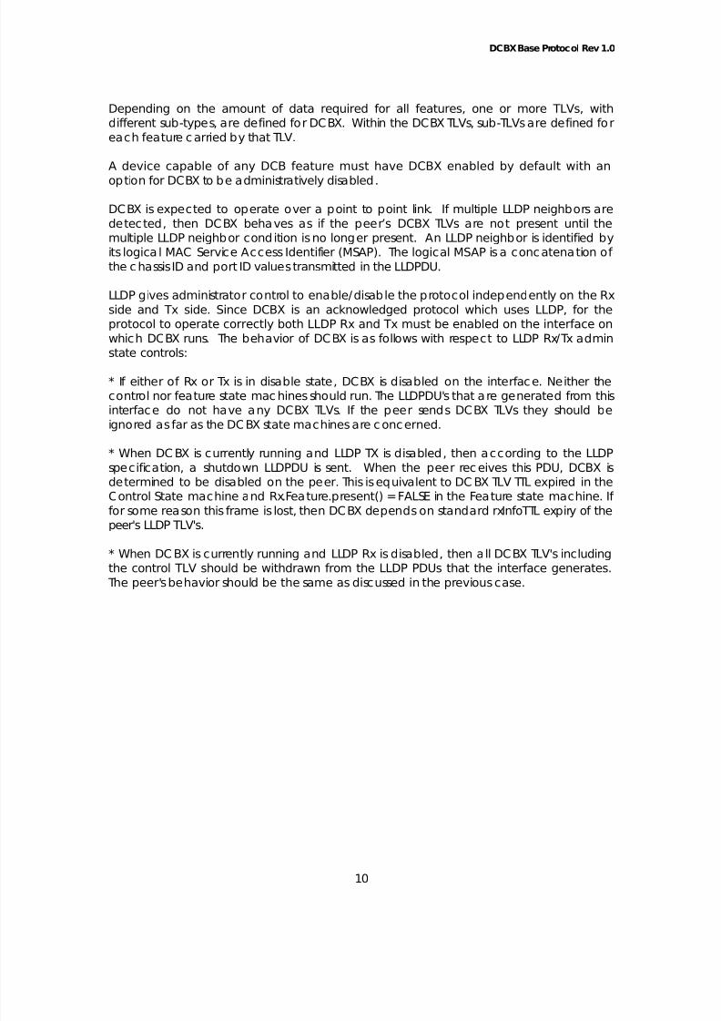
Depend ing on the a mo unt of d ata req uired for all fea tures, one o r more TLVs, with
d ifferent sub -types, are d efined for DCBX. Within the DC BX TLVs, sub -TLVs a re define d for
ea c h fea ture c arried b y that TLV.
A device capable of any DCB feature must have DCBX enabled by default with an
option for DCBX to be administratively disabled.
DCBX is expec ted to op erate over a p oint to p oint link. If multip le LLDP neighbors a re
dete c ted , then DCBX behaves as if the p ee r’ s DCBX TLVs a re not p resent until the
multiple LLDP ne ighb or cond ition is no longer present . An LLDP neighbor is identified by
its log ica l MAC Service Ac cess Ide ntifier (MSAP). The log ica l MSAP is a c onc a tena tion o f
the c ha ssis ID and port ID va lues transmitte d in the LLDPDU.
LLDP gives adm inistrat or co ntrol to ena ble/ d isab le the protoc ol indep end ently on the Rx
side and Tx side . Since DCBX is an ac know led ged protoc ol which uses LLDP, for the
protoc ol to ope rate correc tly bo th LLDP Rx and Tx must be e nab led o n the interface o n
which DCBX runs. The behavior of DC BX is as follow s w ith respec t to LLDP Rx/Tx ad min
sta te cont rols:
* If either of Rx or Tx is in d isab le sta te , DCBX is d isab led on the interfac e. Ne ither the
control nor fea ture sta te ma c hines should run. The LLDPDU's tha t a re g ene ra ted from this
interfac e do not ha ve any DCBX TLVs. If the pee r sends DCBX TLVs the y should b e
igno red as far as the DCBX stat e m ac hines a re c onc erned.
* When DC BX is c urrently running a nd LLDP TX is d isab led , then ac c ord ing to the LLDP
spec ifica tion, a shutdow n LLDPDU is sen t. When the pee r rec eive s this PDU, DCBX is
determined to be d isab led on the pee r. This is eq uiva lent to DC BX TLV TTL exp ired in the
Co ntrol Sta te ma c hine a nd Rx.Fea ture.present () = FALSE in the Fea ture sta te ma chine. If
for som e rea son this frame is lost, the n DCBX dep ends on sta nd ard rxInfoTTL exp iry of the
peer's LLDP TLV's.
* When DCBX is current ly running and LLDP Rx is d isab led , then a ll DCBX TLV's inc lud ing
the c ont rol TLV should b e w ithdraw n from the LLDP PDUs tha t the interfac e g ene ra tes.
The pee r's behavior shou ld b e the same as d isc ussed in the p revious case.
10

5/12/2018 Best_DCBX Protocol Detailed-V1.0 - slidepdf.com
http://slidepdf.com/reader/full/bestdcbx-protocol-detailed-v10 11/29
DCBX Base Protoc ol Rev 1.0
DA SA Ethtype0x88CC
LLDP PDU
Chassis IDTLV
Port IDTLV
Time ToLive
OptionalTLV
Ethernet
Frame format
PROTCOL
Type7 bits
Length9 bits
Information0 - 511 octets General TLV structure
PROTOCOLTLV
End ofLLDPDU TLV
TLVType=127
Length9 bits
OUI3 octets
Subtype1 octet
Information0 – 507 octets
Org TLV HeaderFeatureSub-TLV
FeatureSub-TLV
FeatureSub-TLV
Organizationally SpecificTLV structure
LLDP Pform
PROTOCOLControl Sub-TLV
Figure 3 - LLDP Fram e Form at
2.3.1 LLDP ModificationsThis sec tion lists the p roposed mo d ific a tions to the LLDP protoc ol fo r use w ith DCBX. IEEE
802.1AB REV p rojec t is c urrent ly wo rking on these mo d ific a tions. Onc e stand ard is
pub lished for IEEE 802.1AB-REV, DCBX spec ific a tion w ill be approp ria te ly mod ified .
2.3.1.1 Fast initial LLDP TransmissionsThe c urrent LLDP p roto col can result in a long delay be fore DCB pa rame ters a re
exchang ed and synchronized .
LLDP transmits a fram e a fte r:- Transmit countd ow n timer exp irat ion (recom mende d default value = 30 sec ond s)
and txDelay expiration, OR
- A c ond ition (sta tus or value) change in one or more o b jec ts in LLDP loc a l system
MIB. (LLDP loc a l system MIB c on ta ins on ly the ob jec ts tha t a re sen t in LLDP fram es.
This MIB c ou ld b e m erely a sub set of a larger MIB).
11
After initialization, an LLDP frame is transmitted (considering the initialization as a status
change).
5/12/2018 Best_DCBX Protocol Detailed-V1.0 - slidepdf.com
http://slidepdf.com/reader/full/bestdcbx-protocol-detailed-v10 12/29
DCBX Base Protoc ol Rev 1.0
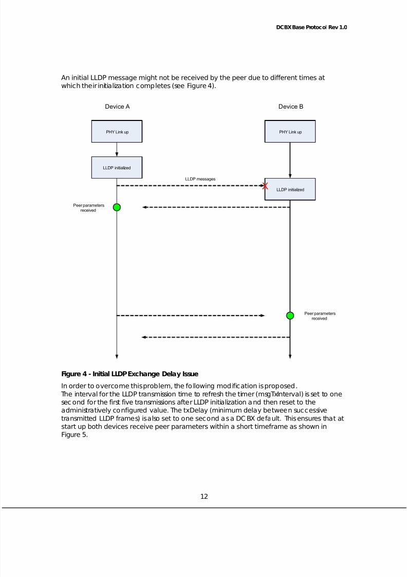
An initial LLDP messag e m ight not be rec eived by t he p ee r due to different t imes at
wh ich the ir initializa tion c om pletes (see Figure 4).
PHY Link up
LLDP initialized
PHY Link up
LLDP initialized
Device A Device B
Peer parametersreceived
Peer parametersreceived
LLDP messages
X
Figure 4 - Initial LLDP Exchange Delay Issue
In orde r to o vercome this p rob lem, the follow ing mod ific at ion is prop osed .
The interva l for the LLDP transmission time to refresh the time r (msgTxInte rval) is set to one
sec ond for the first five transmissions a fte r LLDP initializa tion and the n reset to theadministratively configured va lue. The txDelay (minimum delay be twee n suc c essive
transmitte d LLDP fram es) is a lso set to one sec ond as a DCBX defa ult. This ensures tha t a t
sta rt up both d evice s rec eive p ee r pa ram ete rs within a short time fram e a s show n in
Figure 5.
12

5/12/2018 Best_DCBX Protocol Detailed-V1.0 - slidepdf.com
http://slidepdf.com/reader/full/bestdcbx-protocol-detailed-v10 13/29
DCBX Base Protoc ol Rev 1.0
PHY Link up
LLDP initialized
PHY Link up
LLDP initialized
Device A Device B
Peer parametersreceived
Peer parametersreceived
LLDP Messages
X
X
Figure 5 - Initia l Fast Retransmission of LLDP Fram es
Eac h time LLDP is initia lized , suc h a s link up , LLDP enters this fast t ransmission mode. LLDP
op erates in its norma l transmission m od e a t a ll other times.
2.4 DCBX OperationDCBX is defined as a DCBX c ont rol sta te m ac hine and a set o f DCB fea ture sta te
ma chines. The DCBX c ont rol sta te machine hand les ensuring tha t the tw o DCBX pee rsge t in sync by excha nging LLDPDUs a fter link up or follow ing a c onfiguration chang e.
The DCB fea ture stat e ma chines handle the loc al op erational configura tion for ea ch
fea ture by c om pa ring and synchronizing with the pee r’ s fea ture settings.
13
5/12/2018 Best_DCBX Protocol Detailed-V1.0 - slidepdf.com
http://slidepdf.com/reader/full/bestdcbx-protocol-detailed-v10 14/29
DCBX Base Protoc ol Rev 1.0
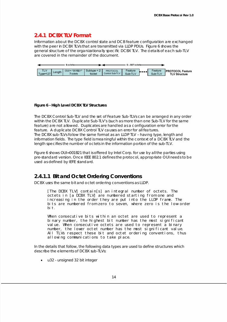
2.4.1 DCBX TLV FormatInforma tion ab out the DCBX c ontrol sta te a nd DCB fea ture c onfigura tion are excha nge d
with the p eer in DCBX TLVs tha t a re transmitte d v ia LLDP PDUs. Figure 6 shows the
general struc ture of the orga niza tiona lly spec ific DC BX TLV. The d eta ils of each sub -TLV
are co vered in the rema inder of the doc ument.
Figure 6 - High Leve l DCBX TLV Struc tures
The DC BX Co ntrol Sub -TLV and the set of Fea ture Sub -TLVs can be a rrang ed in any order
within the DCBX TLV. Dup lica te Sub -TLV’s (suc h a s more tha n one Sub -TLV for the same
fea ture) are not a llow ed . Duplic ate s are hand led a s a c onfigurat ion error for the
fea ture. A d up lic a te DC BX Co ntrol TLV causes an e rror for all features.
The DCBX sub -TLVs fo llow the same forma t a s an LLDP TLV – having typ e, length and
informa tion fields. The t ype field is me aningful within the c ontext of a DCBX TLV and the
lengt h spec ifies the number of oc tets in the informat ion portion of the sub -TLV.
Figure 6 shows OUI=001B21 tha t is offe red by Inte l Corp. for use by a ll the parties using
pre-sta nda rd version. Onc e IEEE 802.1 de fines the p roto c ol, ap propriate OUI nee ds to be
used as defined by IEEE standard.
2.4.1.1 Bit and Oc tet Ordering ConventionsDCBX uses the same b it and oc te t o rdering convent ions as LLDP.
[The DCBX TLV] contain[s] an integral number of octets. The
octets in [a DCBX TLV] are numbered starting from one and
increasing in the order they are put into the LLDP frame. The
bits are numbered from zero to seven, where zero is the low-order
bit.
When consecutive bits within an octet are used to represent a
binary number, the highest bit number has the most significant
value. When consecutive octets are used to represent a binarynumber, the lower octet number has the most significant value.
All TLVs respect these bit and octet ordering conventions, thus
allowing communications to take place.
In the de tails tha t follow , the follow ing d at a types a re used to d efine struc tures which
describe the eleme nts of DCBX sub -TLVs:
14
• u32 - unsigned 32 b it intege r

5/12/2018 Best_DCBX Protocol Detailed-V1.0 - slidepdf.com
http://slidepdf.com/reader/full/bestdcbx-protocol-detailed-v10 15/29
DCBX Base Protoc ol Rev 1.0
• u16 - unsigned 16 b it intege r
• u8 - unsigned 8 b it intege r
Eleme nts listed first in a structu re have lowe r oc tet num be rs then subseq uent e leme nts.
Bit fields within a n elem ent o c c upy t he highe st to lowest o rde r bits of the eleme nt in the
orde r they are listed . The fo llow ing structu re shows an exam p le.
2.4.2 DCBX Control State MachineThe DCBX Control sta te ma c hine uses the DCBX Control sub -TLV to exchange informa tion
with the pe er. In ad dition, it ma intains som e a dd itiona l loc al sta te va riables to m anag e
the sta te m ac hine op eration. The TLV and stat e va riables a re d efined in the sec tions
that follow.
2.4.2.1 DCBX Control TLVFigure 7 shows the DCBX Cont rol TLV.
Figure 7 - DCBX Control TLV Definition
15
struct example_tlv {u16 type :7; // high order bit field in u16 elementu16 length :9; // low order bit field in u16 elementu32 fieldA :8; // highest order bit field in u32 elementu32 fieldB :8;u32 fieldC :3;u32 fieldD :13; // lowest order bit field in u32 element
};
SIZE = 6 octets

5/12/2018 Best_DCBX Protocol Detailed-V1.0 - slidepdf.com
http://slidepdf.com/reader/full/bestdcbx-protocol-detailed-v10 16/29
DCBX Base Protoc ol Rev 1.0
The follow ing ta b le lists the fields in the DCBX Co ntrol TLV.
Table 1 DCBX Control TLV Fields
Field Field -Typ e Range Desc ription
Feature-Typ e
Integ er N/A Type c od e of the DCBX Co ntrolTLV.
Leng th Integer N/ A Leng th of the DCBX Co ntrol sub -
TLV payloa d (not including the
Type and Leng th fields). The
leng th is less tha n the ma ximum
possible va lue (511) as this TLV is
pac kag ed inside the DCBX TLV
a long with o ther fea ture TLV’s.
Oper
Version
Integer 0..255 Op erat ing version of the DCBX
protoc ol. The system ad justs as
need ed to op erate at the highest
version supported by both linkpartners.
Ma x
Version
Inte ger 0..255 Highest DCBX protoc ol version
supported by the system . Version
num bers sta rt at zero. The DC BX
protoc ol must be b ac kward
c omp atible w ith a ll previous
versions.
Seq No Intege r 0 ..
(232 –1)
A value that cha nges ea c h time
an e xcha nged pa rameter in one
or mo re o f the DCB fea ture TLV’s
changes.
Ac kNo Intege r 0 ..(232 –1) The Seq No va lue from the mo strec ent pee r DCBX TLV tha t ha s
be en handled . This
ac knowled ge s to the pe er that a
spe c ific Seq No ha s be en
received.
2.4.2.2 DCBX Control State Va riablesThe following tab le lists the loc a l sta te variab les used to ma intain the DCBX Co ntrol sta te
machine.
Tab le 2 DCBX Control state va riab les
16
State
Variable
Type Rang e Desc ription
RcvdAc kNo Intege r 0 ..
(232 –1)
The ‘ Ac kNo’ from the m ost
recen t p ee r DCBX TLV tha t
ha s bee n hand led . This is an
ac know led ge ment from the
pe er that a spe c ific Seq No

5/12/2018 Best_DCBX Protocol Detailed-V1.0 - slidepdf.com
http://slidepdf.com/reader/full/bestdcbx-protocol-detailed-v10 17/29
DCBX Base Protoc ol Rev 1.0
has be en received.
No DC BXTLV
Received
Boolean TRUE/ FALSE This fla g is set whe n
somethingChangedRemote
eve nt is received from LLDP
and Rem ote M IB indica tes
empty DC B TLVsDCBXFeatur
eUpdate
Boo lea n TRUE/ FALSE Ind ica tes any cha nge in
DCBX Fea ture
2.4.2.3 DCBX Control State MachineIn a dd ition to the TLV fields and sta te variab les p rev iously desc ribed , the DCBX Co ntrol
state machine uses the following mechanisms:
• somethingChangedLocal – this is an indic a tion from t he DCBX sta te m achine to
the LLDP mo dule tha t there is a new DC BX TLV to transmit.
• somethingChangedRemote – this is an ind ica tion from the LLDP mo dule to the
DCBX Control stat e m achine that there is new information from the pee r (such a s
new DCBX TLV or da ta has exp ired ).
• DCBXFeatureUpdate – the DCBX Co ntrol sta te m ac hine p rovides this indica tion to
the DCB Fea ture stat e ma c hines a fter it ha s rec eived the
some thingCha nged Remo te indica tion.
• The SeqNo, DCBXFeatureUpdate and Rc vdAc kNo va riab les a re visible to the DCB
Feature state machines.
Figure 8 show s the o pe ration o f the DCBX Co ntrol sta te m achine. Note tha t the d iagram
is defined using an infinite loo p m od el (suc h as no wa iting). Imp leme nta tions might use
event wa iting me chanisms as long as the function o f the sta te m ac hine is p reserved.
A few notes c onc erning the no ta tions used in Figure 8:
• DCBX Co ntrol TLV fields and sta te variab les a re used d irec tly suc h as Seq No)
• Variab les from the Fea ture sta te m achines a re ide ntified b y pre-pend ing Fea ture
to the va riab le: For examp le, Fea ture.Sync d refers to a va riab le ca lled Sync d
from a Fea ture state ma c hine.
17
• TLV field s receive d from t he p ee r a re iden tified a s: Rx.< variab le> - i.e . ‘Rx.SeqNo.

5/12/2018 Best_DCBX Protocol Detailed-V1.0 - slidepdf.com
http://slidepdf.com/reader/full/bestdcbx-protocol-detailed-v10 18/29
DCBX Base Protoc ol Rev 1.0
Figure 8 - DCBX Control State Mac hine Diag ram
Comm enta ry on the DCBX Control state m ac hine d iagram b y referenc e label (Dx ):
• UpdateDCBXTLV: “C ap ture TLV” te rm imp lies inc lusion o f fea ture TLV to b e
indicated to LLDP for transmission, if the feature is advertised.
• Pee rNotAdvertiseDCBX If the DCBX TLV from the pee r has expired , then the loc a l
side resets simila r to a link up . This is a d ifferent c ase tha n a n a c tua l link dow n,
which wo uld cause this state ma c hine to exit.
• D13: The p ee r has sent a Co ntrol TLV with a new seq uenc e num ber. Send a ne w
Control TLV with an up da ted Ac kNo field .
SeqNo = 0;AckNo = 0;
RcvdAckNo = 0;OperVersion =MaxVersion;
Link up
LinkUp
Do Nothing;
DWait
UCT SeqNo == RcvdAckNo &&Any Feature !Syncd SeqNo++;
somethingChangedLocal = TRUE;Capture all DCBX Feature TLVs
For all Features { FeatureSyncd = FeatureSyncd || !FeatureAdvertise};
UpdateDCBXTLV
SeqNo = 0;AckNo = 0;
RcvdAckNo = 0;OperVersion = MaxVersion;
DCBXFeatureUpdate = TRUE;
PeerNotAdvertiseDCBX(SeqNo != RcvdAckNo || All Features Syncd) &&somethingChangedRemote && NoDCBXTLVReceived
OperVersion =min(Rx.MaxVersion, MaxVersion);somethingChangedLocal = TRUE;
UpdateOperVersion
(SeqNo != RcvdAckNo || All Features Syncd) &&somethingChangedRemote &&!NoDCBXTLVReceived &&OperVersion != min(Rx.MaxVersion, MaxVersion)
RcvdAckNo = Rx.AckNo;DCBXFeatureUpdate =TRUE;
ProcessPeerTLV
(SeqNo != RcvdAckNo || All Features Syncd) &&somethingChangedRemote &&!NoDCBXTLVReceived &&OperVersion == min(Rx.MaxVersion, MaxVersion) &&OperVersion == Rx.OperVersion
AckNo = Rx.SeqNo;somethingChangedLocal=TRUE;
AckPeer
AckNo != Rx.SeqNoAckNo == Rx.SeqNo
UCT
UCT
UCT
UCT
18

5/12/2018 Best_DCBX Protocol Detailed-V1.0 - slidepdf.com
http://slidepdf.com/reader/full/bestdcbx-protocol-detailed-v10 19/29
DCBX Base Protoc ol Rev 1.0
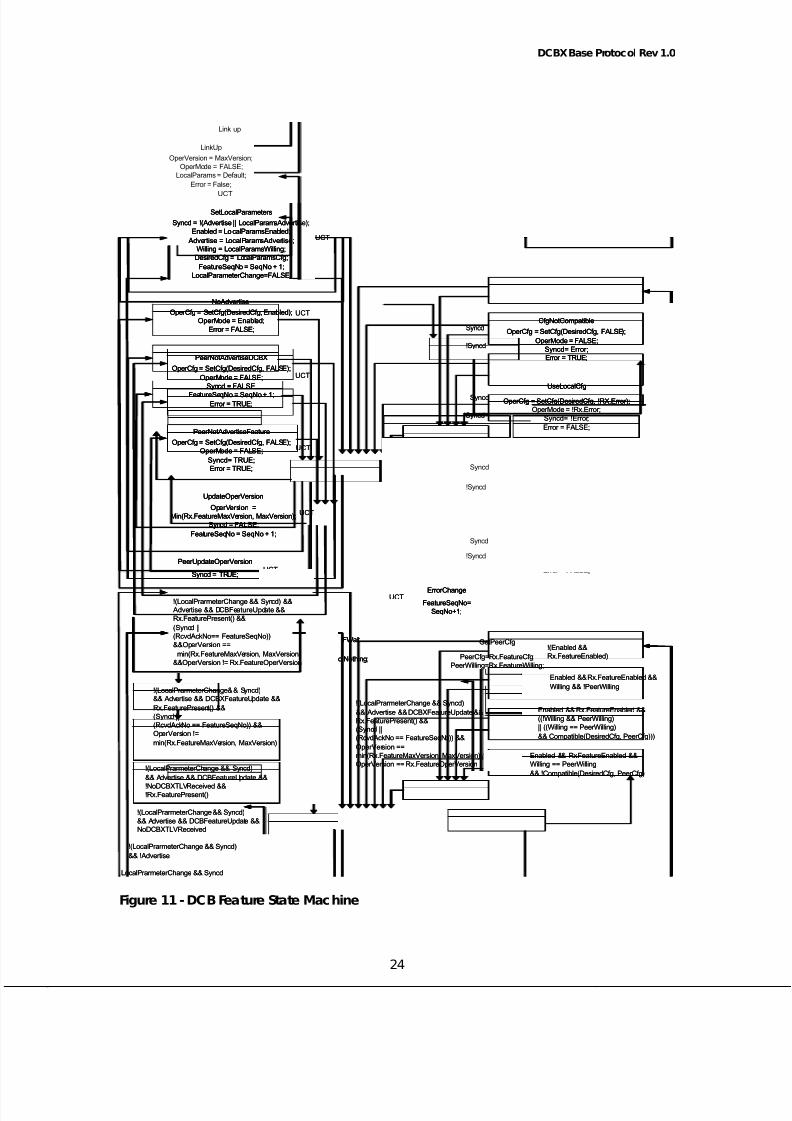
2.4.3 DCB Fea ture State MachineThis sec tion defines the o perat ion of the DCB Fea ture sta te mac hine. The c onfigura tion
of ea c h DCB fea ture is ma nag ed by tha t fea ture’ s DCB Fea ture state ma c hine. All DCB
Fea ture stat e m ac hines op erate in the sam e m anner.
2.4.3.1 DCB Feature TLVFigure 9 shows the c om mo n TLV header struc ture used for a ll DCB fea ture sub -TLV’s.
Fea ture spec ific TLV pa rame ters a re p re-pend ed with this hea der.
16 bits
Type Length
Max_VersionOper_Version
EN
ER
W Reserved Sub_Type
EN=EnabledER = ErrorW=Willing
SIZE=6 Octets
Figure 9 – DCB Fea ture TLV Header Definition (DCBX_tlv_header)
Figure 10 shows a g eneric DCB Fea ture TLV struc ture. The d eta ils of eac h fea ture spec ific
pa ramete r struc ture a re d efined in the up c om ing DCB Fea ture sec tions.
Figure 10 – Generic DCB Fea ture TLV
The follow ing tab le lists the fields in the DC B Fea ture TLVs tha t a re used to define the
op eration of the DCB Fea ture state ma c hine.
Tab le 3 DCB Fea ture TLV heade r field d efinitions
Field Typ e Range Description
Type Integ er 2..127 Type c od e of the DCB Fea ture.
Follow ing is a list o f define d
types:
1 – DCBX Co ntro l (not a
feature)
2 – Priority Groups
19
struct PROTCOL_feature _tlv {struct DCBX_tlv_header h;struct DCBX_feature_cfg desired_cfg;
};
SIZE = 6 + sizeof(struct DCBX_feature _cfg)

5/12/2018 Best_DCBX Protocol Detailed-V1.0 - slidepdf.com
http://slidepdf.com/reader/full/bestdcbx-protocol-detailed-v10 20/29
DCBX Base Protoc ol Rev 1.0
20
3 – Priority-based Flow Co ntro l
Leng th Integer N/ A Length of the DCB Fea ture
sub -TLV pa yload (not includ ing
the Type a nd Length fields).
The leng th is less tha n the
ma ximum possible va lue (511)as this TLV is pac kag ed inside
the DCBX TLV a long with o ther
fea ture TLV’ s.
Oper
Version
Integ er 0 .. 255 Op erat ing version of the
fea ture. The system a d justs to
op erate at the highest version
supp orted b y both link
partners.
Ma x
Version
Integer 0 .. 255 Highest fea ture version
supp orted by the system .
Version numb ers sta rt at zero.
The fea ture must be bac kwardc om pa tib le for all previous
versions.
Ena b le Boo lea n Truth
value
Loc a lly ad ministered
pa ram eter that indica tes
whe ther the DCB feature is
enab led or not.
Willing Boo lea n Truth
value
Loc a lly ad ministered
pa ram eter that indica tes
whether this feature ac ce pts
its c onfigurat ion from the p ee r
or no t. When set to TRUE, the
system uses the DesiredCfgsupp lied by a !Willing p ee r as
the Ope rCfg. A system set to
Willing m ust be c ap able of
ac ce pting a ny valid
DesiredCfg for the feature
from the pe er. If both loc a l
and rem ote system s have the
same va lue for the Willing flag ,
then the loca l Desired Cfg is
used a nd the op erationa l
outcome of the excha nge is
de termined b y the
Comp atible method o f thefeature.
Error Boolea n Truth
value
Ind ic ate s that an error has
oc c urred during the
c onfiguration e xcha nge with
the p eer. Error is a lso set to
TRUE when the Co mp atible
me thod for the fea ture fa ils.
The Fea ture turns Op erMode
5/12/2018 Best_DCBX Protocol Detailed-V1.0 - slidepdf.com
http://slidepdf.com/reader/full/bestdcbx-protocol-detailed-v10 21/29
DCBX Base Protoc ol Rev 1.0
to FALSE if eithe r the loc a l or
rem ote Error flag is set to TRUE.
Dup lic a te TLV’s for the same
Type/ Sub Type o r the DCBX
Control TLV a lso c auses Error to
be set to TRUE.
System e rrors a re not reflec ted
on this Error Flag .
Sub Type Inte ger 0..255 Some Fea ture TLVs ma y define
subt ypes that are spe c ific to
tha t feat ure. When subt ypes
are not d efined by a spe c ific
fea ture, sub type field shou ld
be set to zero
In ge neral, the Type a nd
SubType , ta ken tog ethe r,identify a unique fea ture tha t is
mana ged by an instance of
the DCB Fea ture Sta te
Machine.
NOTE: A node does not have to support 8 classes of service in order to be considered
capable of accepting any valid DesiredCfg. It may fulfill the requirements of the
configuration by combining priorities or priority groups requiring similar service (e.g. PFC
configurat ion and b and width ma nag em ent) into a traffic c lass. Deta ils ab out dec ision to
com bine va rious p riorities in single traffic c lass is out of sc op e of this doc ume nt.
NOTE: The TLV a lwa ys c a rries the DesiredCfg . A system uses its own Desired Cfg , the
peer’s DesiredCfg (PeerCfg) and the other bits (willing, error, etc.) to derive its OperCfg.
When bo th sides adve rtise, they should b e a ble to de rive the sam e O pe rCfg .
2.4.3.2 DCB Fea ture State VariablesThe fo llow ing ta b le lists the a dd itiona l sta te va riab les used to m a intain ea ch DCB Fea ture
state ma c hine.
Tab le 4 DCBX state va riab le definitions for the DCB Fea ture state m ac hine
21
State Variab le Typ e Rang e Desc ription
Ad vertise Boolean Truth
value
Loc a lly ad ministered
pa ram eter that indica tes
whether this fea ture isexchang ed in the DCBX
TLV. When Adve rtise is
Fa lse, received TLVs for this
feature are ignored.
Op erMod e Boo lean Truth
value
Op erational stat e of the
feature.
Fea tureSeq No Integer 0 ..
(232 –1)
When Sync d is Fa lse, this
indica tes the va lue tha t
5/12/2018 Best_DCBX Protocol Detailed-V1.0 - slidepdf.com
http://slidepdf.com/reader/full/bestdcbx-protocol-detailed-v10 22/29
DCBX Base Protoc ol Rev 1.0
Seq No must bec ome e qua l
to b efore Syncd c an
be c om e True.
Sync d Boo lea n Truth
value
Indic ate s whe ther the
c urrent Desired Cfg has
be en rec eived b y the pe er.Op erCfg Struc ture NA The ac tual op erating
c onfigurat ion of the
feature. Derived from
either Desired Cfg or
PeerCfg.
Pee rCfg Structu re NA The Desired Cfg of the pee r
– as rec eived in a DCBX TLV
from the p eer.
DesiredCfg Struc ture NA This rep resents the loc a lly
c onfigured va lues of the
feature specific
configuration.PeerWilling Boolea n Truth
value
The Willing sta te of the p ee r
– as rec eived in a DCBX TLV
from the p eer.
LocalParamete
rChange
Boo lea n Truth
Value
Indic ate s that a
configurable DCB Feature
TLV field or sta te va riab le
has be en mo dified on the
loc a l system .
2.4.3.3 DCB Fea ture State MachineIn a dd ition to the TLV fields and sta te va riab les p rev iously desc ribed , the DCB Fea ture
state machine uses the following mechanisms:
• DCBXFeatureUpdate – this rep resents an ind ica tion from the DCBX Co ntrol sta te
ma c hine tha t the re is new informa tion from the pee r (suc h as a new DCBX TLV or
da ta ha s expired ).
• The Syncd va riab le from ea c h DCB Fea ture sta te m ac hine is visible to the DCBX
Co ntrol sta te ma chine.
• Eac h feature ha s a method c alled Compatible which is used to c om pa re the
Desired Cfg and Pee rCfg.
• Eac h feature retrieves LocalParams from non-volatile sto rage o r sets them to
de fault va lues at link up.
• LocalParameterChange indica tes tha t a c onfigurab le DCB Fea ture TLV field or
sta te va riable ha s been mod ified on the loca l system .• The SeqNo, DCBXFeatureUpdate and Rc vdAc kNo are control sta te ma c hine
va riab les tha t a re visible to the DC B Fea ture sta te m achines.
• Eac h feature ha s a method c alled SetCfg which ac c ep ts two param ete rs. This
me thod is ca lled to set op erational p a ram ete rs for the g iven fea ture. First
pa ram ete r to this me thod provides configuration pa ram ete rs to b e used by the
me thod . Sec ond pa ram ete r is a Boo lean.
22

5/12/2018 Best_DCBX Protocol Detailed-V1.0 - slidepdf.com
http://slidepdf.com/reader/full/bestdcbx-protocol-detailed-v10 23/29
DCBX Base Protoc ol Rev 1.0
Figure 11 show s the o perat ion of the DCB Fea ture sta te m achine. Note tha t the figure is
de fined using an infinite loop model (such a s no w aiting). Imp lementa tions might use
event wa iting me chanisms as long a s the func tion of the sta te m ac hine is p reserved.
A few notes c oncerning the no ta tions used in Figure 11:
• TLV fields and sta te va riab les a re used d irec tly (e.g. Seq No)
23
• TLV fields received from the p ee r a re ide ntified as: Rx.<variab le> - suc h as
Rx.SeqNo.
5/12/2018 Best_DCBX Protocol Detailed-V1.0 - slidepdf.com
http://slidepdf.com/reader/full/bestdcbx-protocol-detailed-v10 24/29
DCBX Base Protoc ol Rev 1.0
!(LocalPrarmeterChange && Syncd) &&Advertise && DCBFeatureUpdate &&Rx.FeaturePresent() &&
(Syncd ||(RcvdAckNo== FeatureSeqNo))&&OperVersion ==
min(Rx.FeatureMaxVersion, MaxVersion)&&OperVersion != Rx.FeatureOperVersion
Syncd = !(Advertise || LocalParamsAdvertise);Enabled = LocalParamsEnabled;
Advertise = LocalParamsAdvertise;Willing = LocalParamsWilling;DesiredCfg = LocalParamsCfg;
FeatureSeqNo= SeqNo + 1;LocalParameterChange=FALSE;
SetLocalParameters
OperCfg = SetCfg(DesiredCfg, Enabled);OperMode = Enabled;
Error = FALSE;
NoAdvertise
Do Nothing;
FWait
UCT
LocalPrarmeterChange && Syncd
!(LocalPrarmeterChange && Syncd)&& Advertise && DCBFeatureUpdate &&NoDCBXTLVReceived
UCT
OperCfg= SetCfg(DesiredCfg, FALSE);
OperMode = FALSE;Syncd = FALSE;
FeatureSeqNo = SeqNo + 1;
Error = TRUE;
PeerNotAdvertiseDCBX
UCT
!(LocalPrarmeterChange && Syncd)
&& !Advertise
OperCfg= SetCfg(DesiredCfg, FALSE);OperMode = FALSE;
Syncd= TRUE;Error = TRUE;
PeerNotAdvertiseFeature
!(LocalPrarmeterChange && Syncd)
&& Advertise && DCBFeatureUpdate &&
!NoDCBXTLVReceived &&!Rx.FeaturePresent(
)
UCT
OperVersion =Min(Rx.FeatureMaxVersion, MaxVersion);
Syncd = FALSE;
FeatureSeqNo = SeqNo + 1;
UpdateOperVersion
!(LocalPrarmeterChange && Syncd)&& Advertise && DCBXFeatureUpdate &&
Rx.FeaturePresent() &&(Syncd ||(RcvdAckNo == FeatureSeqNo)) &&OperVersion !=
min(Rx.FeatureMaxVersion, MaxVersion)
UCT
Syncd = TRUE;
PeerUpdateOperVersion
UCT
!(LocalPrarmeterChange && Syncd)
&& Advertise && DCBXFeatureUpdate &&Rx.FeaturePresent() &&(Syncd ||(RcvdAckNo == FeatureSeqNo)) &&
OperVersion ==min(Rx.FeatureMaxVersion, MaxVersion) &&OperVersion == Rx.FeatureOperVersion
PeerCfg=Rx.FeatureCfg;PeerWilling=Rx.FeatureWilling;
GetPeerCfg
OperCfg = SetCfg(DesiredCfg, FALSE);OperMode = FALSE;
Syncd = !Error;Error = FALSE;
FeatureDisabled
OperCfg = SetCfg(PeerCfg, !RxError);
OperMode = !Rx.Error;Syncd = !Error;
Error = FALSE;
UsePeerCfg
OperCfg = SetCfg(DesiredCfg, !RX.Error);OperMode = !Rx.Error;
Syncd = !Error;
Error = FALSE;
UseLocalCfg
OperCfg = SetCfg(DesiredCfg, FALSE);
OperMode = FALSE;Syncd= Error;Error = TRUE;
CfgNotCompatible
!(Enabled &&Rx.FeatureEnabled)
FeatureSeqNo=SeqNo+1;
ErrorChangeUCT
!Syncd
!Syncd
!Syncd
!Syncd
Syncd
Syncd
Syncd
Syncd
Enabled && Rx.FeatureEnabled &&
Willing && !PeerWilling
Enabled && Rx.FeatureEnabled &&
((!Willing && PeerWilling)|| ((Willing == PeerWilling)
&& Compatible(DesiredCfg, PeerCfg)))
Enabled && Rx.FeatureEnabled &&Willing == PeerWilling
&& !Compatible(DesiredCfg, PeerCfg)
OperVersion = MaxVersion;OperMode = FALSE;
LocalParams = Default;
Error = False;
LinkUp
UCT
Link up
!(LocalPrarmeterChange && Syncd) &&Advertise && DCBFeatureUpdate &&Rx.FeaturePresent() &&
(Syncd ||(RcvdAckNo== FeatureSeqNo))&&OperVersion ==
min(Rx.FeatureMaxVersion, MaxVersion)&&OperVersion != Rx.FeatureOperVersion
Syncd = !(Advertise || LocalParamsAdvertise);Enabled = LocalParamsEnabled;
Advertise = LocalParamsAdvertise;Willing = LocalParamsWilling;DesiredCfg = LocalParamsCfg;
FeatureSeqNo= SeqNo + 1;LocalParameterChange=FALSE;
SetLocalParameters
Syncd = !(Advertise || LocalParamsAdvertise);Enabled = LocalParamsEnabled;
Advertise = LocalParamsAdvertise;Willing = LocalParamsWilling;DesiredCfg = LocalParamsCfg;
FeatureSeqNo= SeqNo + 1;LocalParameterChange=FALSE;
SetLocalParameters
OperCfg = SetCfg(DesiredCfg, Enabled);OperMode = Enabled;
Error = FALSE;
NoAdvertise
OperCfg = SetCfg(DesiredCfg, Enabled);OperMode = Enabled;
Error = FALSE;
NoAdvertise
Do Nothing;
FWait
Do Nothing;
FWait
UCT
LocalPrarmeterChange && Syncd
!(LocalPrarmeterChange && Syncd)&& Advertise && DCBFeatureUpdate &&NoDCBXTLVReceived
UCT
OperCfg= SetCfg(DesiredCfg, FALSE);
OperMode = FALSE;Syncd = FALSE;
FeatureSeqNo = SeqNo + 1;
Error = TRUE;
PeerNotAdvertiseDCBX
OperCfg= SetCfg(DesiredCfg, FALSE);
OperMode = FALSE;Syncd = FALSE;
FeatureSeqNo = SeqNo + 1;
Error = TRUE;
PeerNotAdvertiseDCBX
UCT
!(LocalPrarmeterChange && Syncd)
&& !Advertise
OperCfg= SetCfg(DesiredCfg, FALSE);OperMode = FALSE;
Syncd= TRUE;Error = TRUE;
PeerNotAdvertiseFeature
OperCfg= SetCfg(DesiredCfg, FALSE);OperMode = FALSE;
Syncd= TRUE;Error = TRUE;
PeerNotAdvertiseFeature
!(LocalPrarmeterChange && Syncd)
&& Advertise && DCBFeatureUpdate &&
!NoDCBXTLVReceived &&!Rx.FeaturePresent(
)
UCT
OperVersion =Min(Rx.FeatureMaxVersion, MaxVersion);
Syncd = FALSE;
FeatureSeqNo = SeqNo + 1;
UpdateOperVersion
OperVersion =Min(Rx.FeatureMaxVersion, MaxVersion);
Syncd = FALSE;
FeatureSeqNo = SeqNo + 1;
UpdateOperVersion
!(LocalPrarmeterChange && Syncd)&& Advertise && DCBXFeatureUpdate &&
Rx.FeaturePresent() &&(Syncd ||(RcvdAckNo == FeatureSeqNo)) &&OperVersion !=
min(Rx.FeatureMaxVersion, MaxVersion)
UCT
Syncd = TRUE;
PeerUpdateOperVersion
Syncd = TRUE;
PeerUpdateOperVersion
UCT
!(LocalPrarmeterChange && Syncd)
&& Advertise && DCBXFeatureUpdate &&Rx.FeaturePresent() &&(Syncd ||(RcvdAckNo == FeatureSeqNo)) &&
OperVersion ==min(Rx.FeatureMaxVersion, MaxVersion) &&OperVersion == Rx.FeatureOperVersion
PeerCfg=Rx.FeatureCfg;PeerWilling=Rx.FeatureWilling;
GetPeerCfg
OperCfg = SetCfg(DesiredCfg, FALSE);OperMode = FALSE;
Syncd = !Error;Error = FALSE;
FeatureDisabled
OperCfg = SetCfg(DesiredCfg, FALSE);OperMode = FALSE;
Syncd = !Error;Error = FALSE;
FeatureDisabled
OperCfg = SetCfg(PeerCfg, !RxError);
OperMode = !Rx.Error;Syncd = !Error;
Error = FALSE;
UsePeerCfg
OperCfg = SetCfg(PeerCfg, !RxError);
OperMode = !Rx.Error;Syncd = !Error;
Error = FALSE;
UsePeerCfg
OperCfg = SetCfg(DesiredCfg, !RX.Error);OperMode = !Rx.Error;
Syncd = !Error;
Error = FALSE;
UseLocalCfg
OperCfg = SetCfg(DesiredCfg, !RX.Error);OperMode = !Rx.Error;
Syncd = !Error;
Error = FALSE;
UseLocalCfg
OperCfg = SetCfg(DesiredCfg, FALSE);
OperMode = FALSE;Syncd= Error;Error = TRUE;
CfgNotCompatible
OperCfg = SetCfg(DesiredCfg, FALSE);
OperMode = FALSE;Syncd= Error;Error = TRUE;
CfgNotCompatible
!(Enabled &&Rx.FeatureEnabled)
FeatureSeqNo=SeqNo+1;
ErrorChange
FeatureSeqNo=SeqNo+1;
ErrorChangeUCT
!Syncd
!Syncd
!Syncd
!Syncd
Syncd
Syncd
Syncd
Syncd
Enabled && Rx.FeatureEnabled &&
Willing && !PeerWilling
Enabled && Rx.FeatureEnabled &&
((!Willing && PeerWilling)|| ((Willing == PeerWilling)
&& Compatible(DesiredCfg, PeerCfg)))
Enabled && Rx.FeatureEnabled &&Willing == PeerWilling
&& !Compatible(DesiredCfg, PeerCfg)
OperVersion = MaxVersion;OperMode = FALSE;
LocalParams = Default;
Error = False;
LinkUp
OperVersion = MaxVersion;OperMode = FALSE;
LocalParams = Default;
Error = False;
LinkUp
UCT
Link up
Figure 11 - DCB Fea ture State Machine
24

5/12/2018 Best_DCBX Protocol Detailed-V1.0 - slidepdf.com
http://slidepdf.com/reader/full/bestdcbx-protocol-detailed-v10 25/29
DCBX Base Protoc ol Rev 1.0
Comm enta ry on the DCB Fea ture state ma chine by referenc e label:
• SetLoc alParam ete rs: If multiple fea tures expe rience a c hang e a nd set Syncd to
FALSE, it is possible tha t the first c ha nge t riggers the Co ntrol sta te m achine to sendan LLDP me ssage. Ad d itiona l pend ing changes do no t ge t sent unt il the first
c hang e has be en ac knowledg ed (per D2 of Control state ma c hine). In other
wo rds, the Seq No’s ratc het up a nd a re a cknowledg ed one va lue at a time. For
exam ple, the Ac kNo from the p ee r c ould b e 9, the loc a l Seq No is 10, and
multiple fea tures could b e pend ing with Fea tureSeq No a t 11. A PDU with Seq No
11 is not sent until an Ac kNo o f 10 is rec eived .
• NoAd vertise (any p lac e Op erCfg is set) – The hardw are c onfigurat ion for the
fea ture ta kes plac e a t the p oint Op erCfg is set a nd the O pe rMod e is set. The
imp leme ntation might keep trac k of whether or not the Op erCfg a nd O pe rMod e
have a ctua lly cha nged and req uire an upd ate to the hardwa re c onfiguration.
• Cfg NotC om patible – Error is exp lic itly set to TRUE here to ind ica te tha t the two
pe ers have a DCB c onfigurat ion tha t is not c om pa tible.• SetC fg: When sec ond parame ter (Boo lean) is set to TRUE, then c onfigura tion
pa ssed by first p a ram ete r is ap plied to Op erational va lues. When sec ond
pa ram ete r is “ FALSE” , then b eha vior is fea ture d ep end ent and will be de fined in
the relevant sec tions for eac h fea ture.
2.4.4 Manager NotificationsImp lem enta tions might c hoo se to g ene rate notific at ions whe n ce rta in events oc c ur.
These typ es of events c ould include:
• Conditions indicating possible configuration error –for example, when the
Com pa tible m ethod fails.
• Co nditions whe re the fea ture is not p resent on the p ee r. This c an hap pe n whe n ade vice do es not supp ort a fea ture (not really a n error) or if the fea ture’ s Advertise
flag is off (p ossible c onfigu ra tion e rror).
• The p ee r stop s respond ing – as evidenc ed by an LLDP timeout e ven t (de livered
via the some thingCha nged Remo te indica tion).
• Eac h t ime the Error flag is set to TRUE.
25

5/12/2018 Best_DCBX Protocol Detailed-V1.0 - slidepdf.com
http://slidepdf.com/reader/full/bestdcbx-protocol-detailed-v10 26/29
DCBX Base Protoc ol Rev 1.0
3. DCB FeaturesThis sec tion d efine s the DCB Fea ture p a rameters and sta tistic s.
3.1 Priority Group FeatureThis sec tion d escribes the deta ils of t he Priority Group fea ture. The Priority Groups
Spec ifica tion p rovides c onfigura tion ta bles as well as a sched uling algo rithm for
ma naging b andw idth for various tra ffic c lasses on a c onve rge d link.
NOTE: Althoug h it is expec ted that DCB device s will eventua lly p rovide sched uling
functiona lity a s spe c ified in the Priority Group spe c ifica tion (or b ette r), leg ac y
imp leme nta tions exist. To enc ourage wider ad op tion, this Priority Group Fea ture a llow s
leg ac y imp leme ntations to m atc h sche duler c ap ab ilit ies to the be havior imp lied by
the Priority Group spec ifica tion a s c lose as possible. All DCBX imp leme nta tions must b e
c apab le of a dvertising the Priority Group TLV.
3.1.1 Priority Group ParametersThe follow ing t ab le lists the Priority Group parame ters.
Tab le 5 - Priority Group Paramete rs
Param eter Syntax Rang e Scop e Desc ription
NumTCsSup
ported
Integ er 0..7 Excha nged Numb er of TCs
supp orted b y device.
Number of Priority
Groups suppo rted by a
device c an not be
more than numbe r ofTCs sup ported .
Priority
Group (PG)
Allocation
Tab le
PG ID
(index)
Integ er 0..15 Excha nge d Queue band width
group
PG
Percentage
Intege r 0..100 Excha nged Percentage of link
bandwidth
Priority
Allocation
Tab le
Priority
(index)
Intege r 0..7 Excha nged
PG ID Integer 0..15 Excha nged PG to wh ich the p riority
belongs
3.1.2 Priority Group TLVFigure 12 shows Priority Group pa rameters struc ture tha t is used in the Priority Group
Feature TLV.
26

5/12/2018 Best_DCBX Protocol Detailed-V1.0 - slidepdf.com
http://slidepdf.com/reader/full/bestdcbx-protocol-detailed-v10 27/29
DCBX Base Protoc ol Rev 1.0
Figure 12 - Priority Group Paramete rs Structure
3.1.3 Priority Group Parameter Comp arisonTab le 6 lists how the Priority Group p arame ters of the loc a l and pee r nodes a re
co mp ared to d etermine if they matc h or not.
Tab le 6 - Priority Groups Paramete r Comp arison
Parameter Comparison
Priority Group (PG) A lloc a tion
PG ID (index) Does not need to ma tch
PG Perce ntag e Does not need to ma tch
Priority Allocation
Priority (index) Does not need to ma tc hPG ID Does not need to ma tch
Numbe r of TCs Supp orted Does not need to ma tch
3.1.4 Feature Spec ific Behavior for Priority Group TLVPriority group has spec ific be havior defined for SetC fg m ethod in fea ture state ma c hine.
Based on sec ond pa ram ete r to SetC fg func tion, follow ing ac tions shall be ta ken for
Priority Groups feature:
27
struct dcbx_pg_cfg {u8 pgid_0 :4; /* PGID of priority 0 */u8 pgid_1 :4; /* PGID of priority 1 */u8 pgid_2 :4; /* PGID of priority 2 */u8 pgid_3 :4; /* PGID of priority 3 */u8 pgid_4 :4; /* PGID of priority 4 */
u8 pgid_5 :4; /* PGID of priority 5 */u8 pgid_6 :4; /* PGID of priority 6 */u8 pgid_7 :4; /* PGID of priority 7 */u8 pg_percentage[8]; /* Index is PGID */u8 num_tcs_supported;
}SIZE = 13 octets
5/12/2018 Best_DCBX Protocol Detailed-V1.0 - slidepdf.com
http://slidepdf.com/reader/full/bestdcbx-protocol-detailed-v10 28/29
DCBX Base Protoc ol Rev 1.0
- When Boo lean is set to TRUE, configuration passed by first p arame ter to the
me thod shall be app lied to o pe rat ional values. Fea ture shall be “ Enab led ” .
- When sec ond parame ter (Boo lean) is set to FALSE, loc a l co nfiguration
(Desired Cfg) shall be ap plied to op erational va lues and fea ture sha ll be
“ Enabled” .
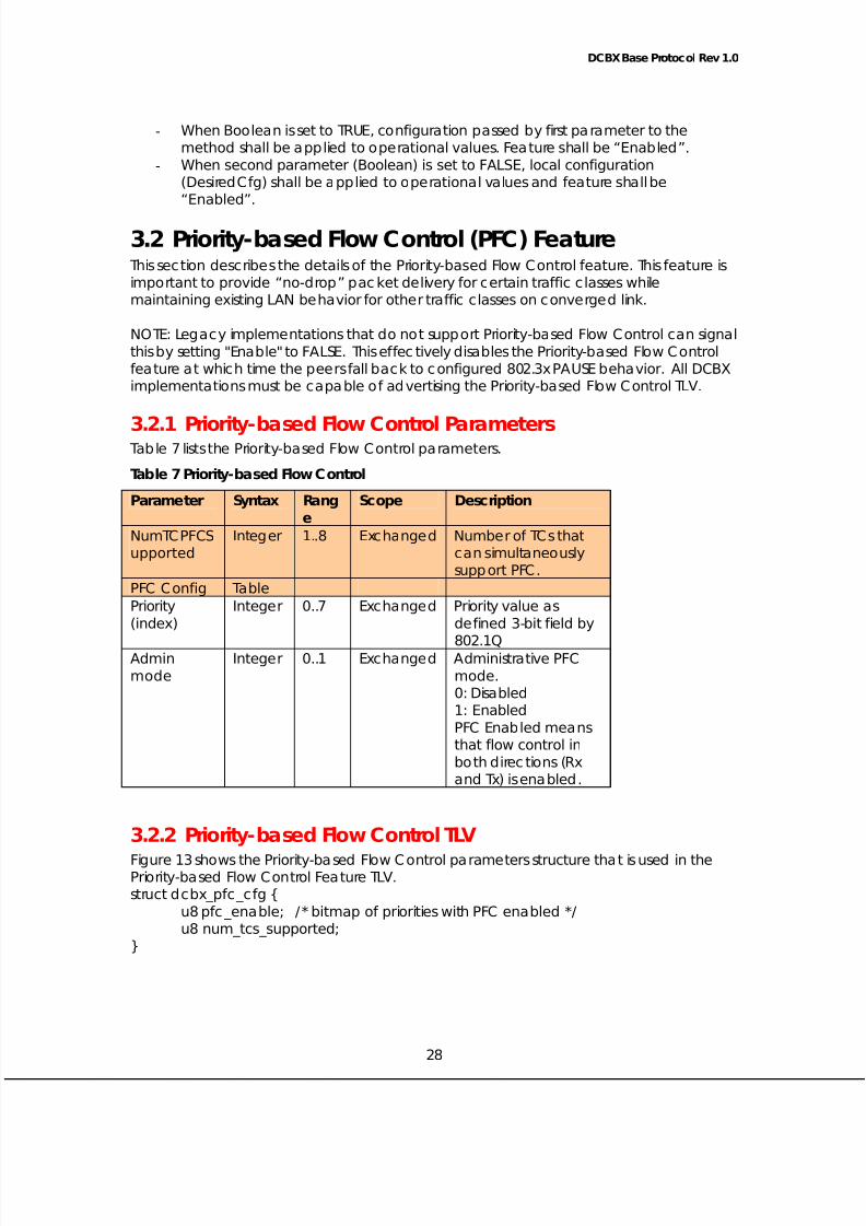
3.2 Priority-based Flow Control (PFC) FeatureThis sec tion d escribes the deta ils of the Priority-based Flow Co ntrol fea ture. This fea ture is
imp ortant to provide “ no-drop” pac ket de livery for ce rta in traffic c lasses while
ma intaining existing LAN beha vior for othe r traffic c lasses on c onverge d link.
NOTE: Leg ac y imp lementa tions tha t do no t support Priority-based Flow C ont rol can signa l
this by set ting "Ena b le" to FALSE. This ef fec tively d isab les the Priority-ba sed Flow Co ntrol
fea ture at w hich time the p ee rs fall bac k to configured 802.3x PAUSE beha vior. All DCBX
impleme nta tions must be c apab le of a dvertising the Priority-based Flow C ont rol TLV.
3.2.1 Priority-based Flow Control ParametersTab le 7 lists the Priority-ba sed Flow Co ntrol p aram eters.
Tab le 7 Priority-b ased Flow Control
Paramete r Syntax Rang
e
Scope Description
NumTCPFCS
upported
Intege r 1..8 Excha nged Numb er of TCs tha t
can simultane ously
support PFC.
PFC Co nfig Tab le
Priority
(index)
Integ er 0..7 Excha nged Priority va lue as
de fined 3-bit field b y
802.1QAdmin
mode
Intege r 0..1 Excha nged Administrative PFC
mode.
0: Disab led
1: Enabled
PFC Enabled means
that flow c ontrol in
both d irec tions (Rx
and Tx) is ena b led .
3.2.2 Priority-based Flow Control TLV
Figure 13 shows the Priority-based Flow Control parameters structure that is used in thePriority-based Flow Co ntrol Fea ture TLV.
struc t dcbx_pfc _c fg {
u8 pfc _ena ble; / * bitmap of priorities with PFC ena b led */
u8 num_tcs_supported ;
28
}
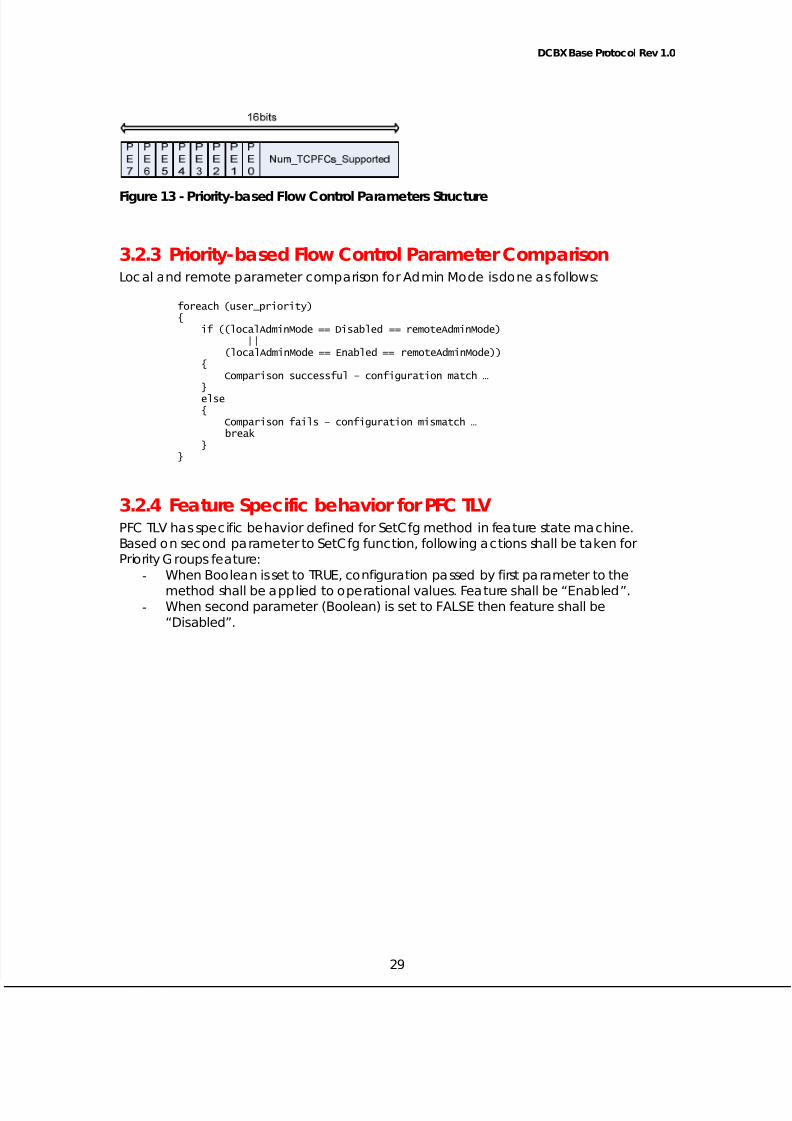
5/12/2018 Best_DCBX Protocol Detailed-V1.0 - slidepdf.com
http://slidepdf.com/reader/full/bestdcbx-protocol-detailed-v10 29/29
DCBX Base Protoc ol Rev 1.0
Figure 13 - Priority-b ased Flow Control Paramete rs Structure
3.2.3 Priority-based Flow Control Parameter ComparisonLoc al and rem ote p aram ete r c om pa rison for Adm in Mod e is done as follow s:
foreach (user_priority){
if ((localAdminMode == Disabled == remoteAdminMode)||
(localAdminMode == Enabled == remoteAdminMode)){
Comparison successful – configuration match …
}else{
Comparison fails – configuration mismatch …break
}}
3.2.4 Fea ture Spec ific behavior for PFC TLVPFC TLV has spec ific beha vior defined for SetC fg m ethod in fea ture sta te m achine.
Based on sec ond pa ram ete r to SetC fg func tion, follow ing ac tions shall be ta ken for
Priority Groups feature:
- When Boolea n is set to TRUE, co nfiguration passed by first pa rameter to the
me thod shall be app lied to o pe rat ional values. Fea ture shall be “ Enab led ” .- When sec ond parame ter (Boo lean) is set t o FALSE then feat ure sha ll be
“Disabled”.
29