bi-sn based low temperature soldering process and...
TRANSCRIPT

Bi-Sn Based Low Temperature Soldering Process and Reliability Call for Project Formation August 17-18, 2015
Initiative Leaders: Raiyo Aspandiar, Mokler, Scott, Intel; iNEMI Staff: Haley Fu

Agenda
• Participants Introduction • iNEMI Project Process • Project Formation Team Objective • Project Preliminary Definition
– Initial Proposal – IS / IS NOT analysis – Discussion
• Next Step & Meetings
2

iNEMI Project Process

• Address knowledge gap(s) of industry: – Common problem – Best solved by working together – Timed success that aligns to business needs – Best manifested on complex far reaching issues – Often includes reliability testing & verification
• Requires teamwork across multiple levels of the supply chain: – Ensures efficient alignment of goals and investments of the varied
team players; – Supports the company’s commercial interests.
• Delivers a coordinated industry wide response and capability set.
– OEM/ODM/EMS/Suppliers at multiple levels.
Successful iNEMI Projects

INPUT SELECTION DEFINITION PLANNING EXECUTION / REVIEW CLOSURE
1
2
3
4
5
The Project Development Process - 5 Steps
“ Project” Limited to committed Members
“ Initiative” Open for Industry input
---------------------------------------------------------------------------------
0
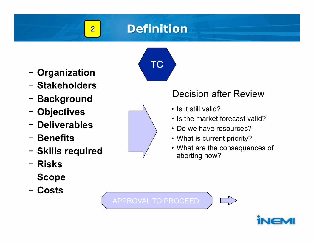
− Organization − Stakeholders − Background − Objectives − Deliverables − Benefits − Skills required − Risks − Scope − Costs
APPROVAL TO PROCEED
• Is it still valid? • Is the market forecast valid? • Do we have resources? • What is current priority? • What are the consequences of
aborting now?
2 Definition
Decision after Review
TC

Planning
− Time estimates − Initial schedule − Resource analysis − Optimization − Risk review − Issue resolution − Prepare to implement
• Is the schedule acceptable to participating member companies?
• Are resources committed? • Do we still want to do it? • Is current priority correct?
3
Decision after Review
APPROVAL TO PROCEED
TC

Output of Planning Process
− Project Leadership − SOW (Statement of Work) − Document Describing the Project
− PS (Project Statement) − Document Defining: − What each Firm Will Contribute − The rules for the Project − Firm Commitment from Management
SOW and PS are described at www.inemi.org
3
APPROVAL TO PROCEED TC

Project Formation Team Objective

Project Formation Team Objective • Plan the project with manageable/achievable
scope to benefit the membership/industry
– Define the project goals and scope – Identify tasks and resources required – Plan the project schedule – Develop the SOW and PS – Identify key players to form the project team
10

Outline of Statement of Work (SOW)
1. Background to work 2. Scope of project 3. Purpose of project 4. What the project IS/IS NOT 5. Business Impact 6. Previous/current related work 7. Outcome of project 8. Prospective Participants
– (Generic – nonspecific list) 9. Project Schedule with Milestones 10. Resources required from project participants 11. Project monitoring plan 12. General and administrative guidelines

Project Proposal
The Starting Point

Problem Statements
Ø ODMs are striving to lower Energy Usage § Higher energy costs are driving ODMs to reduce
power usage in manufacturing process § One major target is reflow ovens -- lowering
temperatures in reflow ovens can save significant amount of energy
Ø SMT Solder Joint Yield Losses are increasing due to the burgeoning of ultra-thin electronic packages and boards § Lowering soldering temperatures lowers package
and board warpage and hence mitigates the solder joint yield loss
13

Proposed Mitigation To Problems
• Use of low temperature solders and solder pastes – Will enable lowering the peak reflow
temperatures which in turn will – Lower energy usage costs – Lower package and board warpage during
reflow soldering

Low Temperature Solders
• Enter Text
15
Medium Temperature Solders [SnAgCu+Bi,In] • melt in the 210 to 220C range
Low Temperature Solders [Bi/Sn/X, X=Ag,Cu,Ni] • melt in the 139 to 175C range
Ø There are a variety of compositions and melting ranges for Potential Low Temperature Solders in Electronics Manufacturing
Ø Bi-Sn system solders are being proposed for this Project Ø More processing and economic benefits than Medium
Temperature Solders

Risk of Bi-Sn based Solders
Source: M. McCormack, H.S. Chen, G.W. Kammlott, and S. Jin, JEM, 26 (8), 1997
Ø Bi-Sn based solders have high strain rate sensitivity Ø At high strain rate the solder is very brittle due to the
bismuth phase within its two phase microstructure Ø This leads to high hisk of brittle fracture of Bi-Sn
based solder joints under of Mechanical Shock and Drop conditions for electronic products
SAC region
Bi-mixed region
Fracture at
IMC-Land Interface
Mechanical
Shock or Drop
Mixed SAC-BiSn BGA Solder Joints Cracking along the solder/IMC interface and in the solder

Resin Reinforced Bi-‐Sn Solder Paste
Duc5le Bi-‐Sn Metallurgy Solder Paste
• Resin added to the solder paste cures during reflow and provides reinforcement under mechanical stresses
Cured Resin
• Addi5on of Elemental Dopants increases duc5lity of Bi-‐Sn solder by modifying microstructure
• Hypoeutec5c Bi-‐Sn composi5ons (40 vs 57 wt% Bi) with added dopants
Potential Solution Paths to Mitigate Risks of Bi-Sn Brittle Solder Joints
SAC Region
Bi Diffused Region
Cured resin
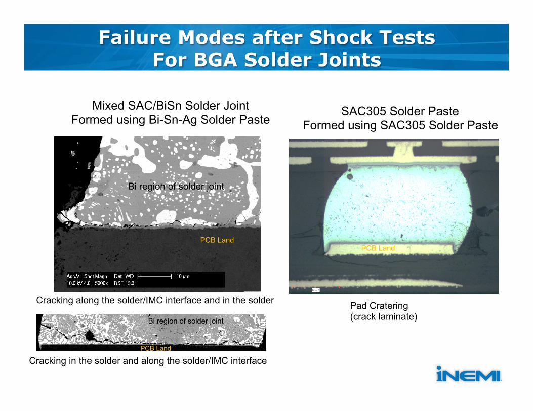
Failure Modes after Shock Tests For BGA Solder Joints
Cracking along the solder/IMC interface and in the solder
Cracking in the solder and along the solder/IMC interface
Mixed SAC/BiSn Solder Joint Formed using Bi-Sn-Ag Solder Paste
SAC305 Solder Paste Formed using SAC305 Solder Paste
Pad Cratering (crack laminate)
Bi region of solder joint
PCB Land PCB Land
PCB Land
Bi region of solder joint

Project Proposal • Objective:
– To assess the two solution paths available for mitigating mechanical drop / shock and thermal cycle risks associated with Bi-Sn based solder pastes for SMT assembly
• Scope – Solder Pastes
• ductile Bi-Sn metallurgy • Resin Reinforced Bi-Sn based • SAC305 (for comparison) • standard BiSnAg (for comparison)
– Components • High density BGAs • BTCs (such as QFNs) • Other
– Board Surface Finishes • OSP (1st option) • ENIG • ENEPIG
– SMT Process Development • Stencil Printing • Reflow Soldering • Rework Process
– Shock/Drop and Thermal Evaluation using Test Vehicle Designs • Shock/Drop is the 1st priority and
thermal is the 2nd • Per JEDEC or other standards
– Product Validation • Boards Assembled with Best
performing solder pastes from each category
• Subjected to selected Product level functional and mechanical shock/drop tests

Proposed Steps
Step # Description Expected Outcome
1 Select Solder Pastes Available from Suppliers in Both Categories - Ductile Bi-Sn - Resin Reinforced Bi-Sn
List of Solder Pastes with TDS containing Recommended Reflow Profiles, and SDS
2 Select Components to be Tested List of Components with their design documents
3 Design Shock Test Boards Board Design Files and Requirement Documents of Shock Test Boards
4 Identify Sites for Board Assembly, Shock Test and Failure Analysis
List of Members Sites where Shock Test Board s will be assembled, Shock Tests conducted and Failure Analysis performed
5 Develop SMT Process -Printing - Reflow soldering
Optimized Stencil Printing Parameters and Reflow Profiles for each solder paste being evaluated
6 Assemble Boards Assembled Boards from each selected member board assembly site
7 Mechanical Shock/Drop Test Boards All test boards subjected to Shock/Drop per Plan and Weibull Plots generated
8 Conduct Failure Analysis Solder Joint Failure locations, modes of failure and microstructural aspects
9 Publish Preliminary Report Completed Report on Mechanical Shock/Drop Test Results

Proposed Steps -- Continued --
Step # Description Expected Outcome
10 Select Best Performing Solder Pastes from Mechanical Shock/Drop Test in each category - Ductile Bi-Sn - Resin Reinforced Bi-Sn
List of one each Ductile Bi-Sn and Resin Reinforced Bi-Sn Solder Paste to be used for Product Validation Steps
11 Select Product Design to be Validated and manufacturing site for assembly and for Validation Tests
Detailed information of Product Board, and BOM with planned Product Validation Tests
12 Procure BOM and assemble Product at selected Manufacturing Site Assembled Product Boards
13 Test Boards through standard Product Functionality and Reliability
Results of Functionality and Reliability with Yields and Failures documented
14 Conduct Failure Analysis Solder Joint Failure locations, modes of failure and microstructural aspects
15 Publish Final Report Completed Report on all Project Outputs

Standard Bi-Sn-Ag Metallurgy Low Temperature Solder Pastes
Manufacturer Manufacturer’s Part Number Metallurgical Composition
AIM NC273LT Bi57Sn42Ag1
Alent CVP-520 Bi57.6Sn42Ag0.4
Indium 5.7LT Bi57Sn42Ag1
Koki T4AB48-M742 Bi57.6Sn42Ag0.4
Inventec Ecorel Free 140-18 Bi57.6Sn42Ag0.4
Senju ECO Solder Paste SHF L25-LT140ZH Sn59-40Bi-0.5Sb-0.5Cu
Shenmao PF602-P68 Bi58-Sn42
Tamura TLF-401-11 BiS8-Sn42

Resin Reinforced Bi-Sn Based Low Temperature Solder Pastes
Manufacturer Manufacturer’s Part Number and Alloy
Alent ü Timberwolf ü Bi-Sn eutectic + Epoxy Resin
Hitachi Chemical
ü UP-300 (standard resin content) ü Bi-Sn Eutectic + Proprietary Resin ü UP-400 (higher resin content) ü Bi-Sn Eutectic + Proprietary Resin
Indium Corp of America ü 723-62-2 ü Indalloy 281 Bi-Sn Eutectic + Proprietary Resin
Panasonic ü CV6511B ü Bi-Sn eutectic + Proprietary Resin
Senju ü L20-JPP-J10(S6)-T7R ü Bi-Sn eutectic + Proprietary Resin
Tamura ü SAM10-401-27 ü BiSn Eutectic Metallurgy
Yincae ü SMT138E ü Solderable Ag containing Epoxy paste

Ductile Bi-Sn based Metallurgy Low Temperature Solder Pastes
Manufacturer Manufacturer’s Part Number and Alloy
Alent ü OM-535 ü SBX02 (Bi-Sn-0.4Ag –X3-X4) eutectic patented Alloy
Senju ü L27-LT142ZH ü Patented Sn-Bi-X1-X2 hypo-eutectic patented alloy

Prospective iNEMI Member Participants
Solder Paste Suppliers Hitachi Chemical Henkel Indium Nihon OEMs Dell HP Intel Lenovo Microsoft
ODMs/EMS Celestica Flextronix Sanmina Wistron Research Institutions Calce RIT SUNY Binghampton
Welcome your active participation and leadership!

Discussion

Is/Is Not Analysis
The Starting Point

IS / IS NOT Analysis
This Project IS: This Project IS NOT: Provide initial analysis of what the Project IS and IS NOT
Guidelines for SOW Development

Outline of Statement of Work (SOW)
1. Background to work 2. Scope of project 3. Purpose of project 4. What the project IS/IS NOT 5. Business Impact 6. Previous/current related work 7. Outcome of project 8. Prospective Participants
– (Generic – nonspecific list) 9. Project Schedule with Milestones 10. Resources required from project participants 11. Project monitoring plan 12. General and administrative guidelines
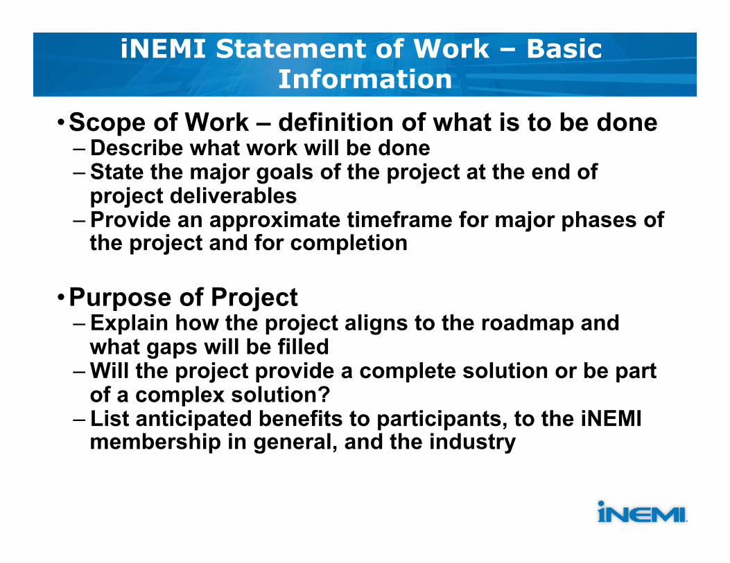
iNEMI Statement of Work – Basic Information
• Scope of Work – definition of what is to be done – Describe what work will be done – State the major goals of the project at the end of
project deliverables – Provide an approximate timeframe for major phases of
the project and for completion
• Purpose of Project – Explain how the project aligns to the roadmap and
what gaps will be filled – Will the project provide a complete solution or be part
of a complex solution? – List anticipated benefits to participants, to the iNEMI
membership in general, and the industry

iNEMI Statement of Work (SOW)
• Business Impact – Provide information on what impact this project will have on
• Participating organization • iNEMI member companies • Industry as a whole
• Outcome of Project – List addressed issues that are expected to addressed and/or
resolved, e.g., identify gaps, report(s) on results of any testing, etc.
– List expected deliverables and project milestones – Sharing Project Results: To be determined by the project
team on what information will be shared outside of the team.
NOTE: All changes to SOW must be approved by TC

Statement of Work – Resources
• Detailed list of resource needs and expenditures expected for the project, including: – Human resources – Equipment – Money
• List of committed resources from participating companies • State source of funding for any components, assembly, design, and
testing needs – Funding alternatives include
• Participant donation • Supplier donation • iNEMI direct funding

Statement of Work – Materials and Processes
• Identify materials to be used • Describe any processes to be used, including applicable standards
and specifications • Identify specific suppliers or technologies required and reasons for
the requirement • When custom components are necessary, state which project
participant is responsible for assuming this cost • Standard processes and materials should be used whenever
possible to reduce costs, improve yields, and assure widest applicability of results within the industry
• Justification is needed if non-standard materials or processes are to be used
• Specify and describe any non-standard materials or processes (Specification Projects)

Statement of Work – Testing Procedures
• State anticipated number of parts to be tested • Use IPC 9701 0-100C as baseline ATC unless justification can be
given for alternate test parameters • For test vehicle design and fabrication, recommend using reference
components that have been ATC tested on previous projects be used to provide a baseline and facilitate comparison of results
• Use standard design practices and commonly used software to reduce costs and widen applicability of results
• At what stages will testing be done along with time needed

Statement of Work – Schedules With Milestones
• Project plan with – Identified tasks – Intermediate check points – End dates
• A detailed timeline, including each project activity
• Content and dates for: – Technical reviews (2 per year) – Progress reports

Statement of Work – Project Monitoring Plans
• Plan to ensure open lines of communication among participants? – Provide planned teleconference schedule – Request progress reports as tasks are completed
• Practice risk analysis by anticipating problems and having alternate solutions ready
• Use opportunity analysis to identify new areas or topics that might be addressed in additional projects – To prevent scope of the current project from expanding – keep project focused on original goals
• Review project requirements with suppliers before the project begins • Provide monthly updates to TIG and TC coach • Provide information as needed to assist in completing Project
Summary Chart

Possible Project Phases
• Definition (Phase 1) – Draft test plan – Fix test parameter – DOE Design – Test Vehicle Design – Phase 1 Interim/Final Report – Revised SOW for Phase 2 – …
• Fabrication (Phase 2) – Test vehicle fabrication – Test vehicle verification – Test vehicle assembly
– Phase 2 Interim/Final Report – Revised SOW for Phase 3 – …
• Testing and Analysis (Phase 3) – Perform tests – Analyze test results – Phase 3 Final Report
• Summary • Lessons Learned
– Final Summary Report – …

Initiative Timeline - Next Meetings
• 1st meeting – kick off and introduction • 2nd meeting – Is/Is not analysis, preliminary definition
• 3rd-5th meeting – experiment design (materials; reliability; test method options; test vehicles; etc.)
• 6th meeting – review the draft SOW, potential resource requirement and high level schedule
• 7th meeting - refine the SOW, prepare the PS; • Submit to TC for approval (2 weeks) • Target to open for sign-up before the end of September
Propose meeting at: 8am China on Tuesday 5pm PDT US on Monday
