bidirectional single sideband transmission of millimeter ... · bidirectional single sideband...
TRANSCRIPT
TecnoLógicas
ISSN-p 0123-7799
ISSN-e 2256-5337
Vol. 21, No. 43, pp. 15-26
Sep-dic de 2018
© Instituto Tecnológico
Metropolitano
Este trabajo está licenciado bajo una
Licencia Internacional Creative
Commons CC BY-NC-SA
Artículo de Investigación/Research Article
Bidirectional single sideband
transmission of Millimeter Waves
over Fiber for 5G Mobile Networks
Transmisión bidireccional en banda lateral
única de ondas milimétricas sobre fibra para
redes móviles 5G
Alejandro Patiño-Carrillo1, Gustavo Puerto-Leguizamón2,
y Carlos Suárez-Fajardo3
Recibido: 04 de junio de 2018
Aceptado: 03 de septiembre de 2018
Cómo citar / How to cite
A. Patiño-Carrillo, G. Puerto-Leguizamón, y C. Suárez-Fajardo,
Bidirectional single side band transmission of Millimeter Waves over
Fiber for 5G Mobile Networks. TecnoLógicas, vol. 21, no. 43, pp. 15-26,
2018.
1 MSc in Mobile Communications, Faculty of Engineering, Universidad
Distrital Francisco José de Caldas, Bogotá-Colombia,
[email protected] 2 PhD in Telecommunications, Faculty of Engineering, Universidad Distrital
Francisco José de Caldas, Bogotá-Colombia, [email protected] 3 PhD in Telecommunications, Faculty of Engineering, Universidad Distrital
Francisco José de Caldas, Bogotá-Colombia, [email protected]
Bidirectional single sideband transmission of Millimeter Wave over Fiber for 5G Mobile Networks
[16] TecnoLógicas, ISSN-p 0123-7799 / ISSN-e 2256-5337, Vol. 21, No. 43, sep-dic de 2018, pp. 15-26
Abstract
This study proposes, experimentally demonstrates, and simulates a network
architecture for the transport of millimeter waves (MMW) based on Radio over Fiber (RoF)
techniques for the transport of signals in the fronthaul segment of the next 5G generation
mobile systems. Such approach exploits the benefits of bidirectional single-sideband
modulation in order to generate an optical subcarrier for the downlink transmission and a
second subcarrier for the transport of the uplink services, as well as the centralization of
optical sources. The proposed architecture is evaluated based on the analyses of the Bit
Error Rate (BER) performance and Error Vector Magnitude (EVM) in both downlink and
uplink. Likewise, simulation modeling of the approach was conducted in order to evaluate
the quality of the MMW signals at different frequencies available in the MMW spectrum.
The results show a power penalty lower than 2 dB for a 1x10-12 BER and an EVM below 12%
within a power margin of 6 dB, which demonstrates the feasibility of the approach.
Keywords
Millimeter Waves, Radio Over Fiber, 5G-fifth generation mobile, Optical centralization
Resumen
Una arquitectura de red para el transporte de ondas milimétricas (MMW) basada en las
técnicas de Radio sobre Fibra (RoF) para el transporte de señales en el segmento de
fronthaul de los futuros sistemas 5G se propone, se demuestra experimentalmente y se
simula en este artículo. La propuesta aprovecha los beneficios de una doble modulación en
banda lateral única para generar una subportadora óptica para la transmisión en el enlace
descendente y una segunda subportadora para el transporte de los servicios en el enlace
ascendente, así como la centralización de las fuentes ópticas. La evaluación de la
arquitectura propuesta se basa en el análisis del rendimiento de la Tasa de Error de Bit
(BER) y la Magnitud de Vector de Error (EVM) tanto en el enlace descendente como en el
enlace ascendente. Del mismo modo, se realizó un modelo de simulación de la propuesta
para evaluar la calidad de las señales en MMW a diferentes frecuencias del espectro
disponible de MMW. Los resultados muestran una penalización en potencia de 2 dB para un
BER de 1x10-12y un EVM inferior al 12% en un margen de potencia de 6 dB, demostrando la
factibilidad del sistema propuesto.
Palabras clave
Ondas Milimétricas, Radio Sobre Fibra, 5G-quinta generación móvil, centralización
óptica.

Bidirectional single sideband transmission of Millimeter Wave over Fiber for 5G Mobile Networks
TecnoLógicas, ISSN-p 0123-7799 / ISSN-e 2256-5337, Vol. 21, No. 43, sep-dic de 2018, pp. 15-26 [17]
1. INTRODUCTION
According to the Cisco Visual
Networking Index (VNI) Report on Global
Mobile Data Traffic 2016-2021, by 2021,
there will be around 5,500 million mobile
phones in the world. The exponential
increase in mobile users, smartphones,
broadband Internet connections, the
Internet of Things paradigm, and the
growing consumption of mobile video will
multiply fixed and mobile data traffic
sevenfold over the next four years [1].
This is one of the reasons why cellular
mobile networks continue their evolution
from previous generations towards 5G,
whose project (IMT-2020 and Beyond)
developed by ITU-3GPP, started in 2012
with a time horizon of eight years [2].
Among the innovations this next
generation will bring is the use of a new
frequency spectrum called millimeter
waves (MMW), whose range lies between
30 and 300 GHz [3]. This spectrum will
mitigate current limitations imposed by
the saturation of frequencies up to 5 GHz.
The use of frequencies in the millimeter
band is considered one of the cornerstones
that will support the fronthaul segment in
future 5G networks [4]. In this context,
transmission techniques based on Radio
over Fiber (RoF) emerged as a mechanism
that allows the convergent transport and
distribution of high frequency signals [5].
Said convergent process, in addition, has
the great advantage of being able to use
the current infrastructure of wireless
networks, thus reducing costs and
deployment times. This characteristic
addresses the previously mentioned access
needs and it offers alternatives for the
provision of services (such as triple play),
trends in cloud computing [6], Distributed
Antenna Systems (DAS) [7] and, in
general, an environment with a growing
number of users. These subscribers
demand quality in telecommunications
services, and they essentially use fiber
optics as transmission lines and radio
systems to enable wireless access and
mobility.
On the other hand, RoF transmission
techniques facilitate the centralization of
Baseband Units (BBU) because the
complex signal processing in the central
office (CO) and the base station (BS) is
very simple, passive, and compact, which
results in less restrictive operation and
maintenance. This kind of systems can
easily serve densely populated areas with
high peaks of traffic and support multiple
wireless standards to increase bandwidth.
These capacities enable to reduce
processing times and improve operations in
dense or small-cell wireless networks given
the nature of the propagation of MMW
signals in free space [8]. By reducing the
cell size, limited spectral resources can be
reused between small cells more
frequently, thus increasing the total
capacity of the system. The combination of
small-cell architecture and higher RF
bands offers a promising solution to
dramatically increase the capacity of
mobile systems by using the new frequency
band [9], [10].
Previous works on optical transport for
5G systems have reported the transmission
of 60 GHz over a 25-km downlink
employing the optical heterodyning of a
laser [11]. For instance, a downlink RoF
technique that can support the distribution
of broadband wireless signals in a
converged optical/wireless system using
digitized radio signals and optical single
sideband is presented in [12]. An
architecture for high-speed multi-service
data transmission based on the concept of
centralized BBU is detailed in [13]. Also,
the exploitation of an optical single
sideband and dual sideband carrier
suppressed in the downlink of the
fronthaul segment is described and
analyzed in [14]. Moreover, a bidirectional
mobile fronthaul system based on
Wavelength Division Multiplexing (WDM)
and non-MMW digitized Frequency
Division Multiplexing (FDM) applied to

Bidirectional single sideband transmission of Millimeter Wave over Fiber for 5G Mobile Networks
[18] TecnoLógicas, ISSN-p 0123-7799 / ISSN-e 2256-5337, Vol. 21, No. 43, sep-dic de 2018, pp. 15-26
support independent asynchronous small
cells is outlined in [15]. Finally, a
bidirectional RoF system for small cells
that uses high speed electro-optical
converters in both directions is introduced
in [16].
This study proposes, experimentally
demonstrates, and simulates an
architecture for bidirectional transmission
of millimeter-band carriers featuring BBU
centralization. Such proposal is based on
the transmission of a bidirectional optical
single-sideband subcarrier generated by a
Mach-Zehnder electro-optical modulator
[17]. One of the single-sideband
subcarriers enables the downlink; another
subcarrier, the uplink. This system also
allows to centralize the optical source by
preventing the use of optical sources on the
base station side.
Fig. 1 shows the environment for the
proposed architecture, in which the BBUs
are centralized in the CO and the
millimeter-band carriers are transported
as optical subcarriers in the Optical
Distribution Network (ODN) [18], between
the CO and BS and vice versa.
This work is organized as follows:
Section 2 presents the mathematic
foundations of optical single-sideband
modulation and the description of the
proposed architecture. Section 3 describes
the experimental results and, finally,
section 4 summarizes the study.
2. MATERIALS AND METHODS
2.1 Theoretical description
The electric field at the output of the
optical modulator is defined, based on the
modulator geometry, as a function of the
incoming electric field and the phase shifts
induced by the electrical signals applied to
the electrodes of the MZ modulator as a
consequence of the electro-optical effect.
When an electrical signal is applied to one
of the two arms of the interferometer, it
causes a phase change in the propagated
optical signal due to the electro-optical
effect.
Fig. 1. Centralization of BBUs for small cells in a 5G environment. Source: Authors’ own work.

Bidirectional single sideband transmission of Millimeter Wave over Fiber for 5G Mobile Networks
TecnoLógicas, ISSN-p 0123-7799 / ISSN-e 2256-5337, Vol. 21, No. 43, sep-dic de 2018, pp. 15-26 [19]
The general expression of the electric
field at the output of the MZM modulator
is given by (1):
)exp()exp()(4
1)( 21
jjtEtE inout
(1)
In turn, the terms of the phase
variation ϕn depend on the bias voltage V.
Such value is defined as the voltage
applied to the electrodes of the device that
causes a phase change of 180° in the
optical signal that propagates in the
waveguide. Likewise, VRF represents the
voltage amplitude in the RF inputs (upper
and lower). Therefore, the phase variation
as a function of these voltages can be
expressed by (2) and (3):
)(1
)(
)(1
)(
1 )( dc
dc
RF
RF
VV
tVV
(2)
)(2
)(
)(2
)(
2 )( dc
dc
RF
RF
VV
tVV
(3)
It is worth mentioning that, since the
optical carrier does not convey information,
terms V1 (dc) and V2 (dc) are null in our
proposal. In order to obtain a single-
sideband RoF system, two RF frequencies
are electrically combined and shifted 90°
with respect to each other before being
applied to the two arms of the optical
modulator. The two copies of the 90º phase-
shifted RF signals are expressed by (4) and
(5):
)cos()()(1 eettetem (4)
)sin()()(2 eettetem (5)
where e(t) represents the information
band; wet, the subcarrier’s frequency; and
αe, the phase signal. Therefore, the
expressions that define the electrical
signals at the input of the modulator are
given by (6) and (7).
Equations (1), (2), (3), (6), and (7) were
used to obtain the general equation that
defines the electrical field at the output of
the modulator for a single-sideband optical
modulation (8).
Note that the exponential and cosine of
the argument are zero for one of the two
expressions (em1 or em2) when there is a
90° phase shift between them, thus a
single-sideband modulated signal is
obtained. The expression for the optical
output power is based on (8) and given by
(9).
eeRF ttetV cos)(2
1
2
1)()(1
)(2
1
2
1)( 1)(1 temtV RF
(6)
2
cos)(2
1
2
1)()(2
eeRF ttetV
eeRF ttetV sin)(2
1
2
1)()(2
)(2
1
2
1)( 2)(2 temtV RF
(7)

Bidirectional single sideband transmission of Millimeter Wave over Fiber for 5G Mobile Networks
[20] TecnoLógicas, ISSN-p 0123-7799 / ISSN-e 2256-5337, Vol. 21, No. 43, sep-dic de 2018, pp. 15-26
Eout (t) =1
2Ein(t)exp
j
2
p
2Vp (RF )
(em1(t)- em2(t))é
ëêê
ù
ûúú
æ
è
çç
ö
ø
÷÷ cos
1
2
p
Vp (RF )
1
2(em1(t)+em2(t)
æ
èç
ö
ø÷
é
ëê
ù
ûú
æ
è
çç
ö
ø
÷÷
(8)
Pout (t) =Pin
81+sin
p
Vp (RF )
1
2(em1(t)+em2 (t)
æ
èç
ö
ø÷
æ
èçç
ö
ø÷÷
é
ëêê
ù
ûúú
Pout (t) =Pin
8
1+ sinp
Vp (RF )
æ
èçç
ö
ø÷÷cos
p
2Vp (RF )
(em1(t)+ em2 (t)æ
èçç
ö
ø÷÷
+cosp
Vp (RF )
æ
èçç
ö
ø÷÷sin
p
2Vp (RF )
(em1(t)+ em2(t)æ
èçç
ö
ø÷÷
é
ë
êêêêê
ù
û
úúúúú
(9)
2.2 Architecture description
Fig. 2 outlines a bidirectional single-
sideband millimeter-wave network over
fiber for the fronthaul link of future 5G
networks. The layout of the downlink is
illustrated on top and the uplink, at the
bottom. This system allows the
centralization of optical sources through
the simultaneous conformation of two
single-sideband optical modulation
schemes. In the CO, a double control MZM
powered by a laser diode is used at a
frequency of 1532.7 nm and an optical
power of 0dBm. Two types of services were
transmitted by two different subcarriers
over the downlink. The first service
consisted of a 1-Gb/s baseband signal
encoded in NRZ over 6 GHz; the second
was a signal at 10 MBauds, 16QAM
modulated onto 6 GHz. One of these
services was injected by one of the arms of
the optical modulator. On the other arm, a
subcarrier was injected at 13 GHz without
modulation (this tone will be used as a
carrier for the uplink). The two RF
subcarriers were shifted 90º by a hybrid
coupler before feeding each one of the arms
of the optical modulator. With this
configuration, one of the sidebands of each
subcarrier is eliminated and a spectral
response is obtained at the output (Fig. 2,
inset a). This combination of signals is sent
through a single-mode fiber span of 5 km
with optical amplification using an
Erbium-Doped Fiber Amplifier (EDFA)
with a gain of 20 dB. At the base stations
(BS), the proposed design consists of a
Fiber Bragg Grating (FBG) centered at the
optical frequency of the 6-GHz modulated
signal. This subcarrier is filtered and
dropped by a circulator, thus allowing
other spectral components to pass through.
The signal reflected in 6 GHz is received by
a PIN photodetector and filtered by a band
pass filter (BPF) to obtain the subcarrier
that will be radiated from the BS to the
users. The optical signal transmitted
through FBG contains the 13-GHz
unmodulated RF signal on which the
uplink information will be transported
(Fig. 2, inset b). Similarly, two types of
services were transmitted in the uplink: (1)
a baseband signal at 1 Gb/s encoded in
NRZ and (2) a signal at 10 MBauds, QPSK
modulated at 13 GHz. After fiber
transmission, the uplink signal is received
and processed in the CO in order to
evaluate its quality.

Bidirectional single sideband transmission of Millimeter Wave over Fiber for 5G Mobile Networks
TecnoLógicas, ISSN-p 0123-7799 / ISSN-e 2256-5337, Vol. 21, No. 43, sep-dic de 2018, pp. 15-26 [21]
Fig. 2. Layout of the bidirectional single-sideband approach for the transport of MMW. Top: Downlink. Bottom:
Uplink. Inset (a): Optical spectrum at the input of the BS. Inset (b): Optical spectrum
at the input of the CO. Source: Authors’ own work.
2.3 Simulation modeling
The proposed approach was evaluated
by assessing the signal quality of the
transported services according to the
millimeter wave and bit rate that were
used. To this aim, a layout featuring the
architecture shown in Fig 2(a) was
implemented in Optisystem v14. Said
layout consisted of a binary generator with
a bit rate of 1 Gb/s, an NRZ pulse encoder,
and an amplitude modulator, whose
operating frequency was swept from 12 to
60 GHz in increments of 6 GHz and fed to
one port of a dual-arm Mach-Zehnder
optical modulator. The other arm was fed a
modulated 10-GHz subcarrier conveying a
1-Gb/s bit rate. In addition, a laser with a
frequency of 193.1 THz was used. The RoF
transmitter fed a 10-km standard single-
mode coil of fiber featuring an attenuation
constant of 0.2 dB/km and a dispersion
Baseband data
Bidirectional single sideband transmission of Millimeter Wave over Fiber for 5G Mobile Networks
[22] TecnoLógicas, ISSN-p 0123-7799 / ISSN-e 2256-5337, Vol. 21, No. 43, sep-dic de 2018, pp. 15-26
parameter of 16.75 ps/km.nm. A carrier
suppression filter with a bandwidth of 5
GHz was introduced on the receiver’s side.
The purpose of said filter is to eliminate
the optical carrier and only allow the
sidebands in order to mitigate the carrier
suppression effect. After photo-detection,
the central frequency of a 10-GHz pass-
band filter was swept following the same
configuration of the transmitter in order to
estimate the quality of the transported
signals.
3. RESULTS
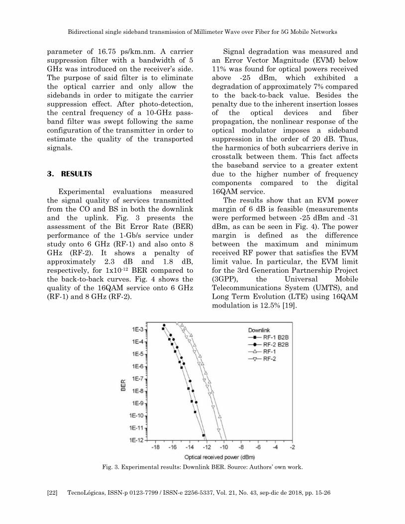
Experimental evaluations measured
the signal quality of services transmitted
from the CO and BS in both the downlink
and the uplink. Fig. 3 presents the
assessment of the Bit Error Rate (BER)
performance of the 1-Gb/s service under
study onto 6 GHz (RF-1) and also onto 8
GHz (RF-2). It shows a penalty of
approximately 2.3 dB and 1.8 dB,
respectively, for 1x10-12 BER compared to
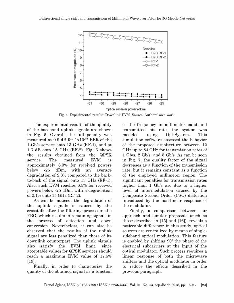
the back-to-back curves. Fig. 4 shows the
quality of the 16QAM service onto 6 GHz
(RF-1) and 8 GHz (RF-2).
Signal degradation was measured and
an Error Vector Magnitude (EVM) below
11% was found for optical powers received
above -25 dBm, which exhibited a
degradation of approximately 7% compared
to the back-to-back value. Besides the
penalty due to the inherent insertion losses
of the optical devices and fiber
propagation, the nonlinear response of the
optical modulator imposes a sideband
suppression in the order of 20 dB. Thus,
the harmonics of both subcarriers derive in
crosstalk between them. This fact affects
the baseband service to a greater extent
due to the higher number of frequency
components compared to the digital
16QAM service.
The results show that an EVM power
margin of 6 dB is feasible (measurements
were performed between -25 dBm and -31
dBm, as can be seen in Fig. 4). The power
margin is defined as the difference
between the maximum and minimum
received RF power that satisfies the EVM
limit value. In particular, the EVM limit
for the 3rd Generation Partnership Project
(3GPP), the Universal Mobile
Telecommunications System (UMTS), and
Long Term Evolution (LTE) using 16QAM
modulation is 12.5% [19].
Fig. 3. Experimental results: Downlink BER. Source: Authors’ own work.
Bidirectional single sideband transmission of Millimeter Wave over Fiber for 5G Mobile Networks
TecnoLógicas, ISSN-p 0123-7799 / ISSN-e 2256-5337, Vol. 21, No. 43, sep-dic de 2018, pp. 15-26 [23]
Fig. 4. Experimental results: Downlink EVM. Source: Authors’ own work.
The experimental results of the quality
of the baseband uplink signals are shown
in Fig. 5. Overall, the full penalty was
measured at 0.9 dB for 1x10-12 BER of the
1-Gb/s service onto 13 GHz (RF-1), and at
1.6 dB onto 15 GHz (RF-2). Fig. 6 shows
the results obtained from the QPSK
service. The measured EVM is
approximately 6.3% for received powers
below -25 dBm, with an average
degradation of 2.3% compared to the back-
to-back of the signal onto 13 GHz (RF-1).
Also, such EVM reaches 6.5% for received
powers below -25 dBm, with a degradation
of 2.1% onto 15 GHz (RF-2).
As can be noticed, the degradation of
the uplink signals is caused by the
crosstalk after the filtering process in the
FBG, which results in remaining signals in
the process of detection and down
conversion. Nevertheless, it can also be
observed that the results of the uplink
signal are less penalized than those of its
downlink counterpart. The uplink signals
also satisfy the EVM limit, since
acceptable values for QPSK services should
reach a maximum EVM value of 17.5%
[19].
Finally, in order to characterize the
quality of the obtained signal as a function
of the frequency in millimeter band and
transmitted bit rate, the system was
modeled using OptiSystem. This
simulation software assessed the behavior
of the proposed architecture between 12
GHz up to 84 GHz for transmission rates of
1 Gb/s, 2 Gb/s, and 5 Gb/s. As can be seen
in Fig. 7, the quality factor of the signal
decreases as a function of the transmission
rate, but it remains constant as a function
of the employed millimeter region. The
significant penalties for transmission rates
higher than 1 Gb/s are due to a higher
level of intermodulation caused by the
Composite Second Order (CSO) distortion
introduced by the non-linear response of
the modulator.
Finally, a comparison between our
approach and similar proposals (such as
those described in [15] and [16]), reveals a
noticeable difference: in this study, optical
sources are centralized by means of single-
sideband optical modulation. This feature
is enabled by shifting 90º the phase of the
electrical subcarriers at the input of the
optical modulator. Such process requires a
linear response of both the microwave
shifters and the optical modulator in order
to reduce the effects described in the
previous paragraph.

Bidirectional single sideband transmission of Millimeter Wave over Fiber for 5G Mobile Networks
[24] TecnoLógicas, ISSN-p 0123-7799 / ISSN-e 2256-5337, Vol. 21, No. 43, sep-dic de 2018, pp. 15-26
Fig. 5. Experimental results: Uplink BER. Source: Authors’ own work.
Fig. 6. Experimental results: Uplink EVM. Source: Authors’ own work.
Fig. 7. Simulation results: Q factor as a function of the MMW frequency. Source: Authors’ own work.
Bidirectional single sideband transmission of Millimeter Wave over Fiber for 5G Mobile Networks
TecnoLógicas, ISSN-p 0123-7799 / ISSN-e 2256-5337, Vol. 21, No. 43, sep-dic de 2018, pp. 15-26 [25]
4. CONCLUSIONS
This paper demonstrated a millimeter
wave radio-over-fiber network architecture
that allows bidirectional transmission of
signals in the context of a future 5G mobile
environment. The novelty of our approach
is the centralization of both mobile
baseband units and optical sources by
simultaneously building two single-
sideband optical modulation schemes. One
of the subcarriers conveys the downlink
information and the other subcarriers in
the base station transport the uplink. A
mathematical description of the single-
sideband optical modulation process was
also presented.
As far as the experimental
demonstration is concerned, the Bit Error
Rate (BER) performance of the 1-Gb/s
service onto 6 GHz (RF-1) and 8 GHz (RF-
2) showed penalties of approximately
2.3dB and 1.8dB, respectively, compared to
the back-to-back curves. The EVM of the
16QAM service onto the same carriers was
below 11% at -25dBm and 7% compared to
back-to-back degradation. These
measurements are satisfactory compared
to the 3GPP standard, which indicates it
should be lower than 12.5% for 16QAM
digital modulation.
The penalties of the uplink for the 1-
Gb/s baseband service and a BER of 1x10-12
were 0.9 dB for the 13-GHz carrier and 1.6
dB for the 15-GHz carrier. For the QPSK
service, the EVM obtained at -25dBm onto
13 GHz was 6.3% and onto 15 GHz, 6.5%.
They suffered a degradation of 2.3% and
2.1%, respectively, compared to back-to-
back curves. These values are even more
satisfactory in terms of the 3GPP
standard, which establishes they should be
lower than 17.5% for QPSK modulation.
When the response of the quality factor
(Q) was characterized as a function of the
frequency and the bit rate, a remarkable
degradation of the Q was observed in rates
higher than 1 Gb/s. These results show
that the approach performs well regardless
of the MMW employed, but the distortions
increase proportionally to the bit rate. The
process to generate the RoF signal of two
subcarriers using only one modulator
causes a great numerical difference in
terms of quality at different bit rates,
because the intermodulation distortion
spreads all over the spectrum. In the
context of a future 5G mobile network,
careful attention must be paid to the setup
of the Mach-Zehnder modulator, since the
bandwidth and extinction ratio must
guarantee that the modulation indexes of
both single-sideband subcarriers does not
surpass its dynamic range. In addition,
alternative approaches such as the use of
two independent modulators should also be
evaluated in order to ensure the capacity
to transport higher bit rates.
5. ACKNOWLEDGMENTS
The authors wish to acknowledge and
thank Universidad Distrital Francisco José
de Caldas and ITEAM Research Institute
for supporting the development of this
study.
6. REFERENCES
[1] Cisco, “Cisco Visual Networking Index:
Global Mobile Data Traffic Forecast Update,
2016–2021 White Paper,” Cisco public, 2017.
[Online]. Available:
https://www.cisco.com/c/en/us/solutions/collat
eral/service-provider/visual-networking-
index-vni/mobile-white-paper-c11-
520862.html.
[2] J. G. Andrews et al., “What Will 5G Be?,”
IEEE J. Sel. Areas Commun., vol. 32, no. 6,
pp. 1065–1082, Jun. 2014.
[3] S. Rangan, T. S. Rappaport, and E. Erkip,
“Millimeter-Wave Cellular Wireless
Networks: Potentials and Challenges,” Proc.
IEEE, vol. 102, no. 3, pp. 366–385, Mar.
2014.
[4] T. S. Rappaport, Y. Xing, G. R. MacCartney,
A. F. Molisch, E. Mellios, and J. Zhang,
“Overview of Millimeter Wave
Communications for Fifth-Generation (5G)
Bidirectional single sideband transmission of Millimeter Wave over Fiber for 5G Mobile Networks
[26] TecnoLógicas, ISSN-p 0123-7799 / ISSN-e 2256-5337, Vol. 21, No. 43, sep-dic de 2018, pp. 15-26
Wireless Networks—With a Focus on
Propagation Models,” IEEE Trans. Antennas
Propag., vol. 65, no. 12, pp. 6213–6230, Dec.
2017.
[5] Jianping Yao, “Microwave Photonics,” J.
Light. Technol., vol. 27, no. 3, pp. 314–335,
2009.
[6] M. Maier and B. P. Rimal, “Invited paper:
The audacity of fiber-wireless (FiWi)
networks: revisited for clouds and cloudlets,”
China Commun., vol. 12, no. 8, pp. 33–45,
Aug. 2015.
[7] P. Chanclou et al., “How Does Passive
Optical Network Tackle Radio Access
Network Evolution?,” J. Opt. Commun.
Netw., vol. 9, no. 11, p. 1030, Nov. 2017.
[8] R. Abdolee, R. Ngah, V. Vakilian, and T. A.
Rahman, “Application of radio-over-fiber
(ROF) in mobile communication,” in 2007
Asia-Pacific Conference on Applied
Electromagnetics, 2007, pp. 1–5.
[9] Gee-Kung Chang, Lin Cheng, Mu Xu, and D.
Guidotti, “Integrated fiber-wireless access
architecture for mobile backhaul and
fronthaul in 5G wireless data networks,” in
2014 IEEE Avionics, Fiber-Optics and
Photonics Technology Conference (AVFOP),
2014, vol. 4, pp. 49–50.
[10] M. Agiwal, A. Roy, and N. Saxena, “Next
Generation 5G Wireless Networks: A
Comprehensive Survey,” IEEE Commun.
Surv. Tutorials, vol. 18, no. 3, pp. 1617–1655,
2016.
[11] C. Browning, E. P. Martin, A. Farhang, and
L. P. Barry, “60 GHz 5G Radio-Over-Fiber
Using UF-OFDM With Optical
Heterodyning,” IEEE Photonics Technol.
Lett., vol. 29, no. 23, pp. 2059–2062, Dec.
2017.
[12] D. Novak et al., “Radio Over Fiber
Technologies for Emerging Wireless
Systems,” IEEE J. Quantum Electron., vol.
52, no. 1, pp. 1–11, Jan. 2016.
[13] C. Liu, J. Wang, L. Cheng, M. Zhu, and G.-K.
Chang, “Key Microwave-Photonics
Technologies for Next-Generation Cloud-
Based Radio Access Networks,” J. Light.
Technol., vol. 32, no. 20, pp. 3452–3460, Oct.
2014.
[14] Y. Tian, K. L. Lee, C. Lim, and A.
Nirmalathas, “60 GHz Analog Radio-Over-
Fiber Fronthaul Investigations,” J. Light.
Technol., vol. 35, no. 19, pp. 4304–4310,
2017.
[15] M. Xu et al., “Bidirectional Fiber-Wireless
Access Technology for 5G Mobile Spectral
Aggregation and Cell Densification,” J. Opt.
Commun. Netw., vol. 8, no. 12, p. B104, Dec.
2016.
[16] P. T. Dat, A. Kanno, and T. Kawanishi,
“Radio on radio over fiber: efficient
fronthauling for small cells and moving
cells,” IEEE Wirel. Commun., vol. 22, no. 5,
pp. 67–75, Oct. 2015.
[17] K. P. Ho and H. W. Cuei, “Generation of
arbitrary quadrature signals using one dual-
drive modulator,” J. Light. Technol., vol. 23,
no. 2, pp. 764–770, 2005.
[18] M. Cely, R. Muñoz, G. Puerto, and C. Suárez,
“Generación de señales para sistemas de
radio sobre fibra basados en la combinación
eléctrica de componentes de banda base y
radiofrecuencia,” Ingeniare. Rev. Chil. Ing.,
vol. 24, no. 3, pp. 403–411, Jul. 2016.
[19] Rohde & Schwarz, O. Werther, and R.
Minihold, “LTE System Specifications and
their Impact on RF & Base Band Circuits,”
2013.