bigboss optical corrector intro to ucl m. sholl 16 july 2010
TRANSCRIPT
BigBoss Optical CorrectorBigBoss Optical CorrectorIntro to UCLIntro to UCL
M. Sholl
16 July 2010

OutlineOutline
• Corrector Design
• Tolerance Study
• Contact with SESO
• Contact with Corning
• Contact with Schott
• Liens on corrector design
• F/8 M2
• Fiber verification camera
• Questions on slides 16 & 17 of CD1 presentation

Telescope RequirementsTelescope Requirements
Requirement Value Description
Compatibility N/A Use existing telescope mount and M1 of Mayall and Blanco 4m telescopes. Include mount for existing f/8 M2.
f/# 4.5 3.8m aperture, 17.1m focal length
Geometric blur <0.8as FWHM
Maximum geometric FWHM (2.35*radius), entire field field (28µm radius)
Zenith Angle 0-60° Will require atmospheric dispersion corrector (ADC) to meet blur requirements
Field of View 3° Full field of view
Wavelength Range
0.35-1.1µm
Simultaneous correction required across entire band
Pointing Jitter <40mas 1-sigma, corresponds to 3µm on focal plane
Fibers 5000
3
Table X1: Telescope requirements

Layout of CorrectorLayout of Corrector
4

University College London (UCL)
• Built similar (but smaller) corrector for DES
• Peter Doel, David Brooks,— Optical Sciences Laboratory, UCL
• LLF6 (used in ADC design) no longer available— LLF6 used on existing Mayall ADC
• Use LLF1 instead— Quick check of Zemax prescription reoptimization suggests it will
work
• Schott can do 980mm LLF1 sizes
• Corning can do fused silica lenses from standard boules— Standard size: 1500mm, 180 & 250mm thick
— Need a homogeneity specification.
• Coatings may be an issue on such large lenses
UCL Suggestions
• Bottom line:— “Cassegrain option would be significantly more expensive (due to
the 2m convex aspheric mirror)”
• Suggest you look into smaller designs, especially first lens

Stray Light
• Instrument must be “Well Baffled”— Stars have no direct view of
focal plane— Prime Focus
• No direct view of focal plane• Only view is reflection off
M1 (signal)
— Cassegrain Focus• Requires optimally sized M1
and M2 baffle• Sweet spot: M1 and M2
baffles’ area fraction equal• Source: Hales, 1992
— Prime focus throughput: 72%— Cassegrain throughput: 63%
• Prime focus design superior in throughput!
DES Corrector
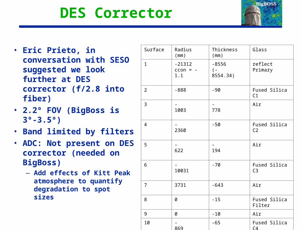
• Eric Prieto, in conversation with SESO suggested we look further at DES corrector (f/2.8 into fiber)
• 2.2º FOV (BigBoss is 3º-3.5º)
• Band limited by filters
• ADC: Not present on DES corrector (needed on BigBoss)— Add effects of Kitt Peak
atmosphere to quantify degradation to spot sizes
Surface Radius (mm) Thickness (mm) Glass
1 -21312ccon = -1.1
-8556 (-8554.34)
reflect Primary
2 -888 -90 Fused Silica C1
3 -1003 -778 Air
4 -2360 -50 Fused Silica C2
5 -622 -194 Air
6 -10031 -70 Fused Silica C3
7 3731 -643 Air
8 0 -15 Fused Silica Filter
9 0 -10 Air
10 -869 a4 = -3.15e-10a6 = -9.48e-16a8 = -4.83e-21
-65 Fused Silica C4
11 -3382 -235 Air
12 1551 -39 Fused Silica C5 (Window)
13 1293 -40 (-41.09) Air
14 0 0 Focal Plane

Spot Sizes Without Atmosphere
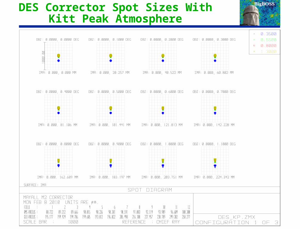
DES Corrector Spot Sizes With Kitt Peak Atmosphere
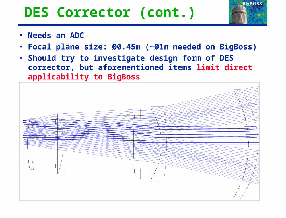
DES Corrector (cont.)
• Needs an ADC
• Focal plane size: Ø0.45m (~Ø1m needed on BigBoss)
• Should try to investigate design form of DES corrector, but aforementioned items limit direct applicability to BigBoss

ADC on BigBossADC on BigBoss
• Two opposite-rotating Risley prisms
• Entrance and exit surfaces of prisms are curved, for aberration control
• Schott Materials—LLF1 (available)
—N-PSK3 (will need to melt)
• ~1° tolerances on prism rotation
12

Spots at 60° from ZenithSpots at 60° from Zenith
13
Risley prism 0° rotation Risley prism 85° rotation

Corrector Tolerance BudgetCorrector Tolerance Budget
• Entire corrector and focal plane moves as a unit (via hexapod). This is system compensator.
• Tolerances may be accommodated by compensator— Manufacturing errors
• Vertex offset
• Figure (measured as surface sag)
• Wedge (measured as distance at lens endge)
• Lens thickness
• Homogeneity (as-built)
— Alignment errors
• Lateral offset
• Despace
• Tilt
• Thermal drift cannot be accommodated in real-time, so it is budgeted as a fixed and “uncomponsatible” error.
14

Tolerance Starting point Tolerance Starting point (preliminary)(preliminary)
• Goal: atmospheric seeing and as-built geometric blur shall have a FWHH < 100 microns
• 120 micron fibers— 5 micron positioner tolerances
— 5 micron fiber view camera accuracy
— 3 micron pointing jitter
• Peak geometric blur on “perfect” design: 18.3 microns RMS— Multiply by 2.35 to convert to FWHH (Gaussian approximation)
— 28 micron blur on as-built design, adds to atmosphere (32 microns RMS) to make a 100 micron FWHH blur
— 282-18.32=450 “quadrature” points, divided 50 ways
— For equal pain, each error source can enlarge the spot from 18.3 to 18.4 microns RMS, after hexapod compensation (where appropriate)
15

Manufacturing Errors (compensated) Manufacturing Errors (compensated) (preliminary)(preliminary)
16
Vertex lateral error
(microns)
Thickness error
(microns)
Wedge (microns at edge)
Surface 1 Radius error
(microns sag)
Surface 1 Conic (%)
Surface 1 A4 (%)
Surface 1 A6 (%)
Surface 2 radius
(microns sag)
Surface 2 Conic (%)
Surface 2 A4 (%)
Surface 2 A6 (%)
Homogeneity (PPM)
C1 100 1000 10 20 20 5
C2 100 250 10 40 50 0.01 0.5 1 5
ADC1_1 100 50 10 100 Flat 5
ADC1_2 100 50 10 Flat 50 5
ADC2_1 100 50 10 100 Flat 5
ADC2_2 100 50 10 Flat 20 5
C3 250 250 15 100 15 0.1 0.1 0.1 5
C4 100 1000 50 50 1 1 1 50
Focal Plane 10000

Alignment Errors (Compensated) Alignment Errors (Compensated) (preliminary)(preliminary)
Lateral Error (microns)
Despace Error from previous surface
(microns)
Tilt Errors (microns at edge)
C1 10 Compensator 10
C2 10 10 7
ADC1 20 100 15
ADC2 30 100 15
C3 50 100 9
C4 75 100 20
Focal Plane 400 100 15
17
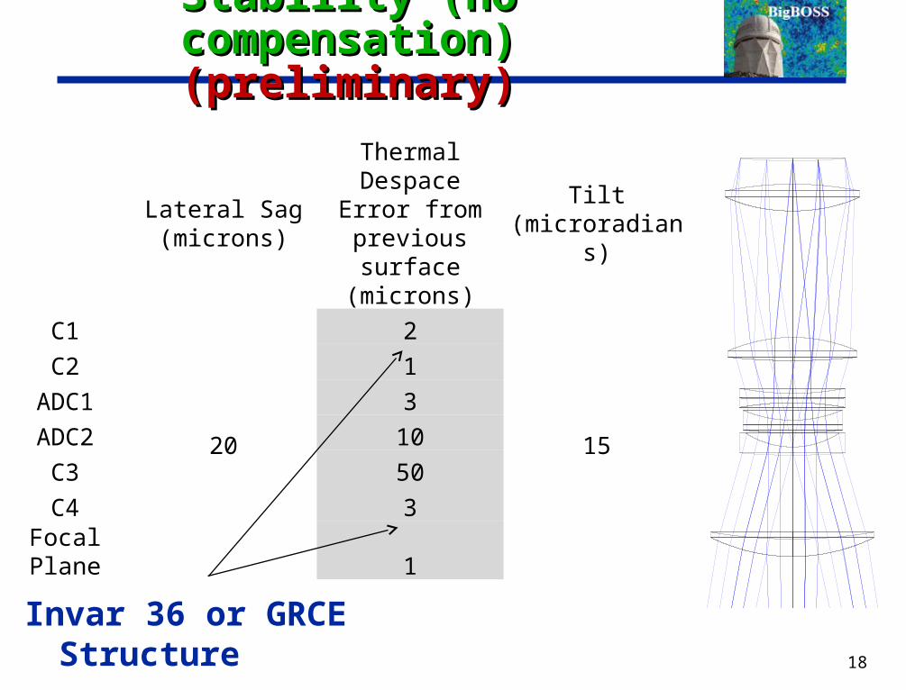
Stability (no compensation) Stability (no compensation) (preliminary)(preliminary)
Lateral Sag (microns)
Thermal Despace Error from
previous surface (microns)
Tilt (microradians)
C1
20
2
15
C2 1ADC1 3ADC2 10
C3 50C4 3
Focal Plane 1
18
Invar 36 or GRCE Structure

Comment on TolerancesComment on Tolerances
• Preceding three slides came from a manual “equal pain” analysis.
• Have already received pushback on uncompensated errors from Eric Anderssen.
• More detailed tolerancing underway…
• Now is the time to push back on these numbers, if they are unreasonable
19

HexapodHexapod
• Motion requirements— Step size: 5 microns (goal) 10 microns (requirement)
— Despace: ±2mm
— Lateral : ±1mm
— Tilt: : ±1°
• PI (Germany) contacted
• ADS-Int. (Italy) to be contacted
20

Corrector Design DetailsCorrector Design Details
21

Contact with SESOContact with SESO
• Spoke with Denis Fappani at SPIE Astronomical Telescopes (June, 2010)— Lens manufacturing generally feasible
— Recommend you thick (50% at center) three ADC elements to reduce gravity sag
— ~2 years to polish, coating extra
— Need to provide figure errors
22

Contact with CorningContact with Corning
• Asked for quote on blanks
23
Item # Material Diameter Thickness Homogeneity
C1 7980 1400mm 220mm 5ppm or better
C2 7980 900mm 180mm 5ppm or better
C4 7980 1160 240mm 5ppm or better
Please advise as to the availability, cost and lead time for these boules. Homogeneity improves the corrector performance, of course, so please let us know if higher homogeneity levels are possible, or if the requested levels are difficult to achieve. The corrector is required to work from 0.35 to 1.1 microns, so material suitability (low absorption) is required in that band.
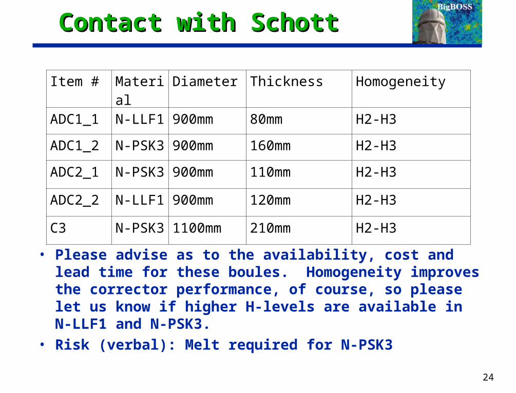
Contact with SchottContact with Schott
• Please advise as to the availability, cost and lead time for these boules. Homogeneity improves the corrector performance, of course, so please let us know if higher H-levels are available in N-LLF1 and N-PSK3.
• Risk (verbal): Melt required for N-PSK3
24
Item # Material Diameter Thickness Homogeneity
ADC1_1 N-LLF1 900mm 80mm H2-H3
ADC1_2 N-PSK3 900mm 160mm H2-H3
ADC2_1 N-PSK3 900mm 110mm H2-H3
ADC2_2 N-LLF1 900mm 120mm H2-H3
C3 N-PSK3 1100mm 210mm H2-H3

Additional ConsiderationAdditional Consideration
• Should accommodate existing f/8 M2
• Existing M2 support appears to be 460mm thick
• M1-f/8 M2 distance: 7491mm
• M1-C1 BigBoss distance: 8800mm
• Removable fiber view camera assembly attaches to same (or similar) interface as f/8 M2
25

Liens on Corrector DesignLiens on Corrector Design
• Thicken three ADC surfaces
• N-PSK3 lens diameter is larger than ADC elements, can it be reduced?
• Adopt sensible curvature (fewer decimal places) for focal plane (constrain during next redesign)
• Improve telecentricity (constrain during next redesign)
• N-PSK3 may be difficult to obtain (per discussion with Schott), and homogeneity may be “best effort.” Different material selection?
26
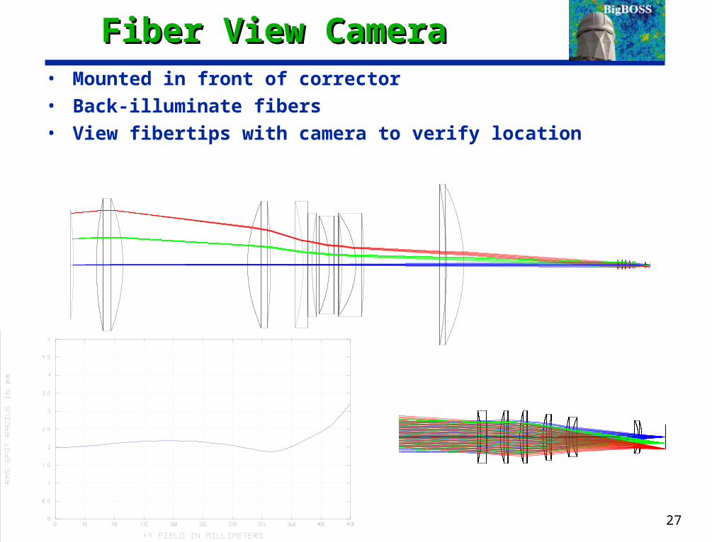
Fiber View CameraFiber View Camera• Mounted in front of corrector
• Back-illuminate fibers
• View fibertips with camera to verify location
27

28
Lens Mounting (Source: DES, P. Doel CD1 presentation, Slide 16)Lens Mounting (Source: DES, P. Doel CD1 presentation, Slide 16)
LBT lens mounting (from Diolaiti et al. SPIE 4841)
Baseline athermal elastomeric (RTV rubber) bonding technique
Looking at two cell options
• Invar lens cell + flexures + thin RTV layer (see figure)
• Steel cell + thick RTV layer

Questions on CD1 Slide 16Questions on CD1 Slide 16
• What is assembly sequence?
• Nonuniform gap an issue?
• What is vertical screw (seems to be touching glass)
• Are glass/invar gradients an issue?
• Large invar difficult to procure?
• What decides thick/thin RTV layers
• Is gravity sag of lens in RTV an issue?
29

30
Lens to Cell Alignment Lens to Cell Alignment (Source: DES, P. Doel CD1 presentation, Slide 16)(Source: DES, P. Doel CD1 presentation, Slide 16)
• Lens to cell
— Lens to cell alignment performed using rotary table and digital dial gauges.
Translation Stage
Rotary Table
D.G.I.
Cell
Cell Adjustment Screws
Lens
RTV inserted into gap

Proposal InputsProposal Inputs
• Any advice on this presentation, and design
• Help/advice (if possible) with tolerance analysis?— Also homogeneity
• Drawings or photos of DES Optical mounts?
• Cost
• Schedule
• Risk
• Test sequence, similar to that of DES? (Brooks presentations)
31