bim based collaborative and interactive design process ... · research article open access bim...
TRANSCRIPT

Edwards et al. Visualization in Engineering (2015) 3:4 DOI 10.1186/s40327-015-0018-2
RESEARCH ARTICLE Open Access
BIM based collaborative and interactive designprocess using computer game engine for generalend-usersGareth Edwards1, Haijiang Li2* and Bin Wang2
Abstract
Background: The emerging Building Information Modelling (BIM) in the Architectural, Engineering and Construction(AEC)/Facility Management (FM) industry promotes life cycle process and collaborative way of working. Currently, manyefforts have been contributed for professional integrated design/construction/maintenance process, there are very fewpractical methods that can enable a professional designer to effectively interact and collaborate with end-users/clientson a functional level.
Method: This paper tries to address the issue via the utilisation of computer game software combined with BuildingInformation Modelling (BIM). Game-engine technology is used due to its intuitive controls, immersive 3D technologyand network capabilities that allow for multiple simultaneous users. BIM has been specified due to the growing trendin industry for the adoption of the design method and the 3D nature of the models, which suit a game engine’scapabilities.
Results: The prototype system created in this paper is based around a designer creating a structure using BIM and thisbeing transferred into the game engine automatically through a two-way data transferring channel. This model is thenused in the game engine across a number of network connected client ends to allow end-users to change/add elementsto the design, and those changes will be synchronized back to the original design conducted by the professionaldesigner. The system has been tested for its robustness and functionality against the development requirements,and the results showed promising potential to support more collaborative and interactive design process.
Conclusion: It was concluded that this process of involving the end-user could be very useful in certain circumstancesto better elaborate the end user’s requirement to design team in real time and in an efficient way.
Keywords: Building Information Modelling (BIM); AEC/FM; Computer game engine; End user; Collaboration
BackgroundBuilding Information Modelling (BIM) is a new technol-ogy/method emerging in AEC/FM industry. It promoteslife cycle process and collaborative way of working. Thebasic concept is that all information/data are shared/up-dated/maintained by all of the involved parties guided/governed by the appropriate governance/managementmodel. BIM allows for design of a building/structure tobe completed in full 3D and also allows for a design tobe modified and updated for all parties so that they can
* Correspondence: [email protected] School of Engineering, Cardiff University, Queen’s Building, TheParade, Cardiff CF24 3AA, WalesFull list of author information is available at the end of the article
© 2015 Edwards et al.; licensee BioMed CentraCommons Attribution License (http://creativecoreproduction in any medium, provided the orig
see the changes almost immediately and see if thosechanges affect their elements of the design. Additionally,BIM enables more specialised parts of the design to becompleted by others, other than the traditional main three(architect, structural engineer and service engineer). Forexample it facilitates conducting energy analysis or quan-tity surveyors to look at the quantities of materials thatmay be required based on the elements parametric data. Italso aids scheduling of the works, known as 4-Dimensional(4D) design. This schedule can be used to create an anima-tion of the construction project, which may be usefulwhen helping professional designer to understand the fullconstruction process or demonstrate it to a client. BIMcan also allow the non-technical parties to understand the
l. This is an Open Access article distributed under the terms of the Creativemmons.org/licenses/by/4.0), which permits unrestricted use, distribution, andinal work is properly credited.

Edwards et al. Visualization in Engineering (2015) 3:4 Page 2 of 17
design at the design stage, to see the design in 3D and geta proper visualisation of the whole project, which is noteasily possible with the more traditional methods.Although, in theory BIM does allow for far greater col-
laboration between many of the parties involved in thedesign process, the current practices and developmentsmainly focus on the collaboration between the differentelements of the professional design teams. Many effortshave been contributed for professional integrated design/ construction / maintenance process, there are very fewpractical methods that can enable a professional designerto effectively interact and collaborate with end users(functionally). Currently, with either BIM or traditionaldesign practices the client is generally only providedwith passive information on a project via the designteam preparing information in some form of formalpresentation. On a functional level BIM has not yetallowed for a client to contribute to the design phase(Christiansson et al. 2011). By this it is meant that all ofthe data that is presented to a client is static and has tobe transferred into some sort of other form with no realinteractive element for the client. An example of thiswould be that the model might be presented on paper oron a computer to a client but the views and informationwill have been pre-prepared by one of the design teamto present to the client and may not present all of theinformation that a client wants to see. This also does notallow the client to actively explore the building in itsentirety and view what they want to see not what adesigner thinks that they want/need to see.This paper introduces a software system development
addressing the technical issue as mentioned aboveregarding the involvements of end users in BIM baseddesign process via the utilisation of computer gameengine combined with BIM (Christiansson et al. 2011;Eastman et al. 2008). A computer game engine is used dueto its intuitive controls (easy enough for non-professionalend users), immersive 3D technology and network cap-abilities that allow for multiple simultaneous users. BIMhas been specified due to the growing trend in industryfor the adoption of the design method and the 3D natureof the models, which suit a game engine’s capabilities.The key contribution is to show a way that allows thefunctional involvement of non-professional end users inthe professional design process. The core research is todevelop a two-way data transferring channel betweenthe end users ‘playing’ in game environment (throughWeb pages or thin client end) and the professional BIMdesign team. The other supporting developments includethe extraction of the necessary information from theprofessional BIM model (through C# based Revit APIdevelopment), game environment development, and set-ting up the underlying computing environment etc. Thedeveloped prototype further extends the current BIM
implementation to cover non-professional end users. Withfurther improvement and development, e.g., embeddedwith the appropriate governance model, it could be usedto realize a more integrated life cycle based buildingdesign/construction/maintenance process to better addressthe end user’s requirements, and hence to improve theefficiency and productivity in the industry.The rest of the paper is organized as follows. First, the
related work regarding computer game engine with BIMapplied in AEC/FM domain has been briefly reviewed,including computer game engine software infrastructureand their various applications. A comprehensive softwaresystem development process is then explained in detail.The software system architecture is introduced first via amulti-layered diagram, which includes the client end,game engine environment, BIM environment and the datatransmission among different elements. The system designand implementation section covers the main hierarchicalsystem design, key classes design and implementation,development framework selection, the implementation fortwo-way data transferring, extraction of BIM data andother development details. The system deployment andevaluation is given next, where several testing scenarioshave been implemented to check the software deve-lopment errors and system functionalities. Finally, theconclusion and future work are given.
Game engine applied in AEC/FM domain with BIMBuilding Information Modelling (BIM) is now approachingto its tipping point (NBIMS 2007; BSI 2010; BuildingSmart2010; McGraw_Hill_construction 2010) worldwide to revo-lutionize the entire workflow for AEC industry. Like othercountries all over the world, the UK has completed severalstrategic BIM implementation plans, which are going torequire BIM compatibility (level 2 of BIM in Bew &Richards Figure (BuildingSmart 2010)) by the year of 2016.There is a drive from the current UK AEC industry toimplement the comprehensive and advanced BIM practiceto fulfil the government requirement. While computergame engines have been developed over the years fromsimple games such as the first interactive computer gameOXO (Obituary 2011) to fully immersive 3D environments.Games are highly profitable, thus developers are willing toinvest heavily in resources for games development. Thisgives rise to a highly developed product. The net result isthat games represent a pinnacle that other simulation andvirtualisation software struggle to equal (Stuart 2011). Allof this leads to very powerful tools that can be used forvarious purposes.One of the situations that computer game engine tech-
nology is being applied to is that of simulating evacu-ation of the population of a building in a situation suchas a fire (Rüppel & Schatz 2011). The models used insome of these simulations are based on 3D information

Edwards et al. Visualization in Engineering (2015) 3:4 Page 3 of 17
taken from BIM applications (Yan et al. 2011). Some ofthe models use agent based systems where the computerbased players are programmed using parameters gainedfrom research and the computer simulates the virtualplayers attempting to evacuate the building (Rüppel &Schatz 2011). This has been extended and changed frombeing simply a fully computer driven simulation to oneutilising the interactivity of the game engine by humansubjects to identify how they react within the simulationand what decisions they make in the stressful situationof a fire. Rüppel and Schatz (2011) took this simulationfurther introducing stimuli such as smoke machines and3D optical effect screens etc. to try to bring a new dimen-sion to the game.Another way in which computer game engines have
been put to use when combined with BIM is that ofproviding an interactive visualisation of a structure. Thishas been done in (Yan et al. 2011) using a combinationof the Microsoft® XNA™ Framework as the game engineand Autodesk® Revit® Architecture as the BIM designapplication. The system allows users to go on a ‘walk-through’ from one room to another or simply explorethe building freely as they wish. This allows for a farmore intuitive method of exploring a design before it isbuilt or whilst the building is under construction whencompared to the static 2D drawings produced by mostCAD based systems. The system also makes full use ofthe parametric property aspect of the BIM designprocess by using the properties that indicate if roomsare linked by a door etc. to allow for path finding in thebuilding. A further use that game engines appear to suitis one of visualising a simulation in a graphical way.They suit themselves to this situation well due to theirreal-time, high quality 3D graphics capabilities and alsotheir ability to cope with 3D geometric data.El Nimr and Mohamed (2011) used two different sce-
narios and two different game engines to achieve visuali-sations of the simulations that they were running. Thefirst example was that of a system designed to simulatethe bidding process for attaining a project from tender.It used a map on which the simulation created jobs thatplayers could then bid for. The second example used areal-life construction scenario and a system was developedto visualise the construction process on a site where partsof the structure were to be built off-site. These werebrought to a yard on site for further assembly into mod-ules that were then finally constructed into the finishedstructure. This system simulated the whole constructionprocess and visualised both the site, enabling the contrac-tors to visualise where cranes could fit on to the siteduring the construction, and also the yard where theindividual parts were to be assembled into modules. Bothof the scenarios demonstrated the merit of having agraphical representation of the simulation, which allowed
for the developers and also the users of the systems to seewhat was going on and where that fitted into the project.Using a computer game engine as part of a design
review system may not seem the obvious choice. How-ever, due to the nature of the game engine providingnetworking features that enable real-time collaborationand real-time 3D graphics for real-time visualisation of abuilding, a game engine could perform this task well.Currently many of the design review systems that areavailable provide insufficient allowance for the inclusionof all of the stakeholders who may sensibly contribute tothis process. Current methods generally are conductedusing peer review. An example of this is the use of alight box to overlay drawings to facilitate discrepanciesto be identified between different elements of the design.Due to this sort of process becoming tedious it is foundthat the process is quite often not conducted efficiently andin some cases is not conducted at all (Shiratuddin & Thabet2011). A prototype has been created by (Shiratuddin &Thabet 2011), where a game engine has been used to createa game where multiple users (members of the design team)can review a design together and interact with the design.They can see details about the design and do basic 3Dediting. It is also possible to communicate with oneanother within the game and leave notes on the design.The authors envisaged that this sort of design review sys-tem will help to improve the quality of the design reviewthat it is undertaken and make it a simpler, easier andmore satisfying process.Another area that game engines have been used for in
AEC is that of teaching students about construction sitesafety (Lin et al. 2011; Dickinson et al. 2011). In work byLin et al., a game was created that simulates a construc-tion site. The user walks around the site looking for errorsor issues with health and safety. When an issue is identi-fied the user selects the issue and then chooses what iswrong with the situation using the games interface. It wasnoted that, from the students who were test subjects inthe work, the system made the learning process moreinteractive and enjoyable and that it helped them to mem-orise the health and safety issues. In addition, such virtualenvironment can enable end users to learn various designskills (Sun et al. 2014; GU et al. 2009). Sun et al. developeda 3D virtual space towards a synchronous distributeddesign meeting system to allow end-users to sketch ormake annotations and have discussions as well as addviewpoints to designs. Gu and Nakapan discussed thebenefits and shortcomings of virtual worlds for collabora-tive design learning and education.In short, computer game engine has becoming much
more advanced and mature (than it was before) to beutilized for AEC/FM industry. In its essence, BIM is lifecycle based collaborative process, which would be muchmore effective if end user gets involved in an efficient

Edwards et al. Visualization in Engineering (2015) 3:4 Page 4 of 17
manner right from the beginning stage through to build-ing’s demolition. Due to the prompt and direct involve-ments of end user/client (on a functional level), withgood governance model, the way of working can furtherfacilitate the prompt response coming from professionaldesigners, and to some extent it can also mitigate thesuffer for designer to repeatedly correct errors due to thelack of effective communication between the end user/client and designer. The development to be introduced inthis paper would serve as a good add-on to other develop-ments focusing more on professional teams (Eastmanet al. 2008; Gu et al. 2010; Hassanien Serror et al. 2008).
MethodsSystem design and implementationThe use of game engines provides new and excitingopportunities for technologies such as BIM. However,this sort of utilisation is still in its infancy. CurrentlyBIM does not provide a method to involve the end-usersof the structures and promote collaboration betweenthem and the design team. This paper proposes to addressthis issue by trying to promote collaboration between thedesign teams and the end-users. The new developed sys-tem has to be tested for its robustness and functionalityagainst the development requirements, and the resultsshowed promising potential to support more collaborativeand interactive design process between professionals andend-users.In order to construct a BIM based collaborative design
environment, the following steps have been identified andconcluded to guide the design of the system, and themulti-layered system architecture is showed in Figure 1.
� Identification of the program suite the designer willuse to create their designs
� Establish how the designs will be conveyed to theend-user
Figure 1 system overall architecture.
� Ascertain how to enable the user to have a simpleand intuitive process to modify designs
� Determination of a method to transfer theinformation relating to these changes to the designer
� Identification of the modules, data sources andexecutables that are required to support the task.
� Plan the order and structure of the implementation.� Plan the methods used for evaluation and testing of
the system.
The multi-layered system architecture comprises fourinter-connected layers (Wang et al. 2014):
� BIM environment: Autodesk Revit can be regardedas a comprehensive building information provider towork with game technology to build an adaptableimmersive serious game
� The data transmission element: Revit plug-incontains the database and FBX format converter. Itworks as ‘micro’ web-server to generate semanticand geometric data and store it in the database tobuild a two-way and dynamic information flow forcollaborative and interactive design.
� Game Engine environment: Unity game includes theUnity server and client game. A unity servercomponent connects Unity clients into an instanceand feeds those clients the available data which iscreated in the data component. Unity clients are theinterface that helps immerse the end-user into thevirtual environment which is generated by the Unityserver (controlled by the designer).
� The client end: End-users and designers can worktogether in different platforms supported by Unitygame engine with appropriate input and outputdevices, i.e. Windows or Mac operating systems thatuse high-resolution monitors with keyboard andmouse; 3D stereoscopic projector with Razer Hydra

Edwards et al. Visualization in Engineering (2015) 3:4 Page 5 of 17
joystick; Hand Mounted Display (HMD) withMicrosoft Kinect Sensor; Mobile platform using iOSor Android with touch screen and built-in camera;or Web-based environment that allows users toconnect to the server through their web browser.
Implementation framework selectionThe major consideration in determining the choice ofsystem development framework was that of compatibilityof many of the BIM standards that have been laid down.A further significant consideration was one of third partysupport with software development kits. Taking thesefactors into account, Autodesk® Revit® Architecture wasselected being fully compatible with BIM standards andhaving excellent third party developer support (AEC (UK)BIM Standard for Autodesk Revit (2010)). It should benoted that the system would also function with Autodesk®Revit® Structure and Autodesk® Revit® MEP (Revit 2012API 2011) (when working with different professionals).The method of enabling the end-user/client to be pre-sented with and modify information contained within theBIM model must meet the following criteria. The methodmust be able to display the 3D nature of the model andprovide a simple, intuitive interface. This method mustalso provide some way to facilitate the end-user/client tocollaborate with other stakeholders. A suitable system thathas been decided upon is that of a game engine. A gameengine provides powerful real-time 3D graphics, network-ing features that allow for collaboration and a simple andintuitive interface (Moore 2011; Petri et al. 2014). Unity3D from Unity Technologies has been chosen as the plat-form to interact between the professional designer and theend user/client. This particular engine has been chosendue to its simple object orientated and editor based designsystem. It also provides many features that other enginesdo not such as the ability to create executables that willrun on both Microsoft® Windows® and Apple® Mac®. Italso provides the ability to create ‘Web player’ versions ofany game produced, which will be a useful tool when pro-viding a method of simple delivery to the end user as itwould mean that the end user could use their own webbrowsers without having to download and install thegame. Currently to use the Unity web player a plug-inmust be installed into the web browser being used. Thismay be negated by using the support for creating anAdobe® Flash® Player object in the 3.5 version of Unity thathas been released recently (at the time of writing). Adobe®Flash® Player is a common web technology is utilised onalmost all modern websites.
Key classes designAll the classes developed in the system help to deliverthe collaborative design environment. Figure 2 showsthe work flow that occurs within the game.
When the server starts up, the first procedure to im-plement is to create an instance in the database to storethis information via the menu system. Next it waits forthe building information to load. The loading time variesdepending on the amount of information in the BIMmodel. The internal process of loading data is to convertRevit building format to FBX format. Then the FBXmodel is loaded into the Unity server’s memory and con-verted into our custom format, which buffers at the net-work layer for incoming clients to load. The client firstneeds to connect to the server by entering the server IPaddress, and then receive the building information. Thetwo highlighted grey sections are specific for the clientversion of the game and their counterparts are specific-ally for the server version of the game. The end userscan control the avatar and toggle main menu for differ-ent tasks in the server and clients.The entire system development follows a sound software
engineering approach, specific activities such as applyingmetrics and identifying characterisations such as designrequirements (aforementioned) and the level of details areimportant in that activity. In relation to the object orientedsoftware development approach used, the overall systemclass hierarchy to constitute menu structure and game forcollaborative and interactive design is shown in Figures 3and 4, and the following contents show the key classesdesign details.All of the classes except ‘OBJModel’ are inherited from
‘MonoBehaviour’, which is Unity’s base class.
Main menuThe ‘MainMenu’ class which is a single script attachedto the camera object in the ‘MainMenu’ game scene inthe Unity game. As can be seen (in Figure 4) it has fourvariables of which three are public to allow access tothem in the Unity editor. These three public variablesare a skin for the GUI components to use, a backdropfor the menu and the title or name of the game to displayon the menu. These three variables are common on allof the menu scenes as is the fourth variable ‘isLoading’,which is private and is used for determining if the gameis changing scenes between a menu scene or the gamescene. Finally it can be seen that there is a subroutine‘OnGUI()’ which is a Unity built in subroutine that getscalled by the game and is used to create the GUIelements and in this case implement the logic for thebuttons of the main menu.
Start serverThe ‘StartServer’ class, which is attached to the cameraobject in the ‘StartServer’ scene. This being a menu hasthe same variables as the main menu and they will notbe described again. It also has some other variables,which are all for the various settings used for the server.

Figure 2 Activity UML model for game flow.
Edwards et al. Visualization in Engineering (2015) 3:4 Page 6 of 17
All of the variables are all public other than the playernumber as they need to be accessed by the Unity editorto allow the default settings to be specified. The ‘Update()’ subroutine, which is built in Unity subroutine thatexecutes once per frame render in the game. It is imple-mented here to allow for capturing of input keys namelythe ‘escape’ key to get back to the main menu. The‘PlayerName’ is included to set a default player prefer-ence as part of the network connection starting process.This starting of the game server is initiated in the
‘OnGUI()’ subroutine along with the other functionalityfor the controls including moving to the lobby scene.
Connect to serverThe ‘JoinServer’ class is attached to the main camera inthe game scene ‘JoinServer’. It also again implements allof the previous standard menu variables and the ‘OnGUI()’ subroutine. Other than those variables and subrou-tines it implements two private variables that are used tohold the value of two text input fields for use as settings

Figure 3 Menu structure of the game.
Edwards et al. Visualization in Engineering (2015) 3:4 Page 7 of 17
when trying to connect to a server version of the game.The three other subroutines that are implemented areUnity built in subroutines that as their names suggestdeal with various situations of network connectivity andare, in this case, only used to send messages to thedebug log. Again the ‘OnGUI()’ subroutine has beenused to implement the functionality of the controls in-cluding initiating the connection with the server versionof the game and changing to the lobby scene.
Lobby menuThe ‘Lobby’ class is attached to the main camera object inthe ‘Lobby’ scene. It implements all of the menu variablesand the ‘OnGUI()’ subroutine. Of the four other variablesthat are implemented two are used for allocating eachplayer (client) a unique number and the other two areused for allocating the settings that the game server willuse to connect the building model server (Revit® plug-in).The ‘Update()’ subroutine is implemented to capture the‘escape’ key input to return to the main menu. The ‘Awake()’ subroutine is another Unity built in subroutine thatinitiates before any of the rest of the class starts, unlikethe ‘Start()’ subroutine where some of the class is startedbefore the function runs. It is used to run what is knownas a Remote Procedure Call (RPC), which is essentially amethod of allowing the same function or subroutine to beinitiated on all connect games, in different locations, atthe same time. It runs the RPC subroutine ‘GetPlayer-Number()’, which in turn runs another RPC, namely‘ReturnPlayerNumber’ from the clients so that they eachrequest a player number from the server. The functional-ity of the controls, which are only shown on the gameserver not the clients, is implemented in the ‘OnGUI()’subroutine including executing the ‘LaunchGame()’ RPC
on all clients that makes the server and all clients changescenes to the ‘Game’ scene.
Player in gameThe ‘MovePlanar’ class is attached to the ‘Player’ prefab,which is an object that can be instantiated (created)across the network. There are five public variables toallow for the editor to set the values of them before thegame is complied. These include speed factor which areused in setting the speed of movement of the player, arotational sensitivity, which again is essentially a speedfactor and the Skin to use for the GUI. There are also anumber of Boolean type variables that are used to enableand disable motion and menus depending on inputssuch as the ‘escape’ key, which is captured in the‘Update()’ subroutine along with the input and imple-mentation of the movement algorithm. There is also the‘Position’, which is of Vector3 type (3D vector), is usedfor maintaining the position of the player across thenetwork on the clients games. The ‘Awake()’ subroutineis used to get the RigidBody component of the ‘Player’prefab to use for enabling and disabling gravity. The‘OnGUI()’ is again used for implementing a menu that isonly displayed after the ‘escape’ key has been pressedwith functionality such as exiting the game or enablingmotion in the Y axis plane, whilst disabling the gravityoption of the RigidBody component. Two other Unitybuilt in subroutines are also used in this class. ‘OnSeria-lizeNetworkView()’ is used for sending informationabout the state of gravity and position of the ‘Player’ pre-fab across the network to the other players (clients). Thesecond subroutine ‘OnNetworkInstantiate()’ is used toensure that the camera is correctly configured to be theone that is a child of the ‘Player’ prefab.
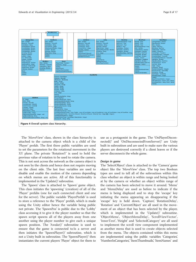
Figure 4 Overall system class hierarchy.
Edwards et al. Visualization in Engineering (2015) 3:4 Page 8 of 17
The ‘MoveView’ class, shown in the class hierarchy isattached to the camera object which is a child of the‘Player’ prefab. The first three public variables are usedto set the parameters for the rotational movement in theXY plane. The private ‘RotationY’ is used to hold theprevious value of rotation to be used to rotate the camera.This is not sent across the network as the camera object isnot seen by the clients and hence does not require movingon the client side. The last four variables are used todisable and enable the motion of the camera dependingon which menus are active. All of this functionality isimplemented in the ‘Update()’ subroutine.The ‘Spawn’ class is attached to ‘Spawn’ game object.
This class initiates the ‘spawning’ (creation) of all of the‘Player’ prefabs (one for each connected client and onefor the server). The public variable ‘PlayerPrefab’ is usedto store a reference to the ‘Player’ prefab, which is madeusing the Unity editor hence the variable being publicnot private. The ‘SpawnPos’ is public due to the ‘Lobby’class accessing it to give it the player number so that thespawn script spawns all of the players away from oneanother using the player number to give each a uniquespawn position. The ‘Awake()’ subroutine is used toensure that the game is connected to/is a server andthen initiates the ‘SpawnPlayer()’ subroutine, which isnot a Unity built in subroutine. The ‘SpawnPlayer()’ theninstantiates the current players ‘Player’ object for them to
use as a protagonist in the game. The ‘OnPlayerDiscon-nected()’ and ‘OnDisconnectedFromServer()’ are Unitybuilt in subroutines and are used to make sure the variousplayers are destroyed correctly if a client leaves or if theserver disconnects the whole game.
Design in gameThe ‘SelectObject’ class is attached to the ‘Camera’ gameobject like the ‘MoveView’ class. The top two Booleantypes are used to tell all of the subroutines within thisclass whether an object is within range and being lookedat by the camera or whether an object within range ofthe camera has been selected to move it around. ‘Menu’and ‘MenuDelay’ are used as before to indicate if themenu is being displayed and to stop the ‘escape’ keyinitiating the menu appearing an disappearing if the‘escape’ key is held down. ‘Capture’, ‘RotationDelay’,‘Rotation’ and ‘CurrentObject’ are all used in the move-ment of an object that has been selected by the player,which is implemented in the ‘Update()’ subroutine.‘ObjectMenu’, ‘ObjectMenuDelay’, ‘ScrollViewVector’,‘InnerText’, ‘Height’ and ‘SelectedCategory’ are all usedto implement the scroll view component implementedas another menu that is used to create objects selectedfrom the menu. The objects contained within this menuare implemented using the public variables ‘Categories’,‘NumberInCategories’, ‘ItemThumbnails’, ‘ItemNames’ and

Edwards et al. Visualization in Engineering (2015) 3:4 Page 9 of 17
‘ItemPrefabs’. These allow for the specification of categor-ies using the ‘Categories’ variable along with the numberof items contained in that category using ‘NumberInCate-gories’. The items three details, their names, thumbnailimages and references to their prefabs, are then placedin the same order as the categories in the other threevariables. All of this scroll view is implemented in the‘OnGUI()’ function up until an item is selected by pressinga button containing the thumbnail of an object. This thenruns the ‘SpawnFurniture()’ subroutine, which creates aninstance of the selected prefab in front of the player. Thisin turn runs the ‘SetPositons()’ RPC, which moves theobject on the other players games to its start position.The ‘MoveObject()’ RPC is supposed to allow for move-ment of the objects by sending the name of the objectto be moved and also the name of parent (player) thatwill be moving the object. It then utilises these namesto find the objects and tries to move the object with theparent object (player).
Data communication between BIM environment andclient endThe realization of BIM data extraction for computergame engine is through using C# based Revit API devel-opment. Figure 5 shows the class for BIM data extractionand the extraction process. The ‘StartGameEngineViewer’class is used to deal with all of the functionality containedin the plug-in. It is initialised by the button on the ribbonbar created in the ‘AddInPanel’ class. The first functionthat is called in the ‘StartGameEngineViewer’ class is thebuilt in Revit API function ‘Execute()’. Therefore, the ‘Exe-cute()’ function is public because the ‘AddInPanel’ classneeds to access it. The global variables in this class areused mainly due to there being a background worker thatruns on a separate thread, which still needs access to some
Figure 5 Plugin class and data extraction process.
of the data. The ‘OBJFile’ variable is used to hold a fullcopy of the ‘.obj’ file for the current building model. The‘uidoc’ variable is used to hold a handle to the currentdocument in Revit®. This is so that all of the functions andthe background worker can access the document. The‘listener’ is object that makes up the ‘mini’ web-serveralong with the background worker ‘bgWorker’. The ‘Do-main’ and ‘PORT’ variables are used to hold variables forthe settings for the listener. The ‘CloseListener’ is used sothat the main thread can make the background workerthread terminate. The ‘AppName’ variable is used to holdthe name of the plug-in as it may be used in the requeststo the ‘listener’ object and will need to be identified in arequested URL and removed.Figure 6 shows the ‘ReadBJFile’ and ‘OBJModel’
classes, which are attached to the ‘BuildingModel’ gameobject. The class ‘ReadOBJFile’ allows for the creation ofthe building by getting the geometric and some paramet-ric data from the plug-in in Revit® using ‘.obj’ (Wave-front 3D) files. The class ‘OBJModel’ is used to create anarray of the individual objects contained in the buildingmodel within the ‘ReadOBJFile’ class. The ‘OBJModel’class essentially is just a container for the variables itneeds to hold, which are the ID number and name ofthe element. It has implemented get and set functionsfor both of these variables. It also holds an array of 3Dvectors (Vector3) for the vertices and the normal’s to thefaces, which specify the direction in which a face isvisible from. ‘OBJModel’ also holds an array of 2D vec-tors used to hold the vertex textures or UVs, which areused to position a texture on a face of the model cor-rectly. Finally there is an array of integers that is used tohold a list of indexes to the vertices, normals and UVsused to define each triangle that makes up the mesh ofthe object.
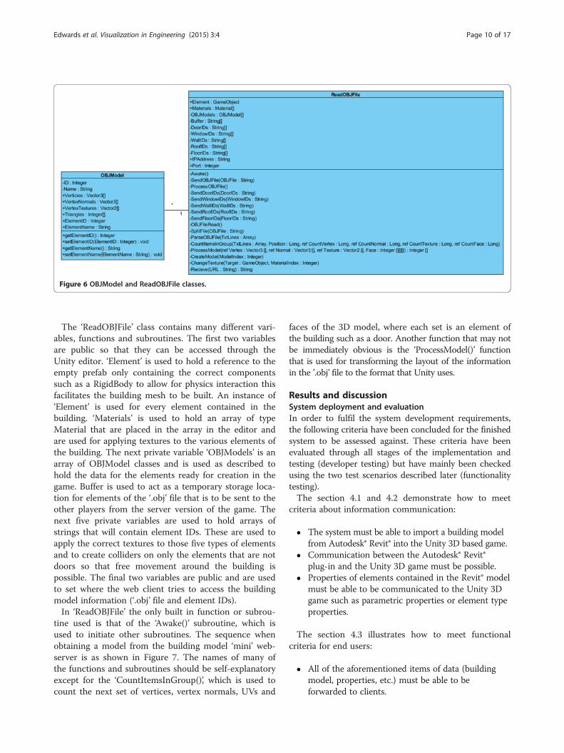
Figure 6 OBJModel and ReadOBJFile classes.
Edwards et al. Visualization in Engineering (2015) 3:4 Page 10 of 17
The ‘ReadOBJFile’ class contains many different vari-ables, functions and subroutines. The first two variablesare public so that they can be accessed through theUnity editor. ‘Element’ is used to hold a reference to theempty prefab only containing the correct componentssuch as a RigidBody to allow for physics interaction thisfacilitates the building mesh to be built. An instance of‘Element’ is used for every element contained in thebuilding. ‘Materials’ is used to hold an array of typeMaterial that are placed in the array in the editor andare used for applying textures to the various elements ofthe building. The next private variable ‘OBJModels’ is anarray of OBJModel classes and is used as described tohold the data for the elements ready for creation in thegame. Buffer is used to act as a temporary storage loca-tion for elements of the ‘.obj’ file that is to be sent to theother players from the server version of the game. Thenext five private variables are used to hold arrays ofstrings that will contain element IDs. These are used toapply the correct textures to those five types of elementsand to create colliders on only the elements that are notdoors so that free movement around the building ispossible. The final two variables are public and are usedto set where the web client tries to access the buildingmodel information (‘.obj’ file and element IDs).In ‘ReadOBJFile’ the only built in function or subrou-
tine used is that of the ‘Awake()’ subroutine, which isused to initiate other subroutines. The sequence whenobtaining a model from the building model ‘mini’ web-server is as shown in Figure 7. The names of many ofthe functions and subroutines should be self-explanatoryexcept for the ‘CountItemsInGroup()’, which is used tocount the next set of vertices, vertex normals, UVs and
faces of the 3D model, where each set is an element ofthe building such as a door. Another function that may notbe immediately obvious is the ‘ProcessModel()’ functionthat is used for transforming the layout of the informationin the ’.obj’ file to the format that Unity uses.
Results and discussionSystem deployment and evaluationIn order to fulfil the system development requirements,the following criteria have been concluded for the finishedsystem to be assessed against. These criteria have beenevaluated through all stages of the implementation andtesting (developer testing) but have mainly been checkedusing the two test scenarios described later (functionalitytesting).The section 4.1 and 4.2 demonstrate how to meet
criteria about information communication:
� The system must be able to import a building modelfrom Autodesk® Revit® into the Unity 3D based game.
� Communication between the Autodesk® Revit®plug-in and the Unity 3D game must be possible.
� Properties of elements contained in the Revit® modelmust be able to be communicated to the Unity 3Dgame such as parametric properties or element typeproperties.
The section 4.3 illustrates how to meet functionalcriteria for end users:
� All of the aforementioned items of data (buildingmodel, properties, etc.) must be able to beforwarded to clients.

Figure 7 Data transferring process.
Edwards et al. Visualization in Engineering (2015) 3:4 Page 11 of 17
� Models of furniture and other items must be able tobe placed by an end user on a client version of thegame or by the designer into the building model.
� Where client (end users) versions of the game place amodel in their game the information about that placedobject must be sent to the server version of the game.
� The designer must be able to transfer informationabout the objects placed by the clients back toAutodesk® Revit®. The plug-in will then load thisinformation into the building model.
The following sections demonstrate the collaborativedesign system prototype working as intended, whenassessed against the evaluation criteria. All of these teststhroughout the testing section were carried out in a net-worked computing environment running Microsoft®Windows® 7 with Autodesk® Revit® 2012 and Unity 3.4installed.
Setting up the linking between BIM modelling & gameengineThe plug-in appears in the ribbon bar of Autodesk®Revit® as a button that will initiate the exporting of themodel and set-up the building model server. This plug-in is shown in Figure 8 in the ‘Add-Ins’ Section of theRevit® Ribbon Bar.The form shown in Figure 8 at the bottom, allows for
the changing of settings for the ‘mini’ web-server. Thesesettings include the Internet Protocol (IP) address thatthe server listens on and also the Port that the server
listens to. Finally there is a check box to indicate if thegame is to be run on the local machine. This optionlaunches the game in its current location on the localmachine automatically after the ‘mini’ web-server hasstarted. The plug-in also has another form that isdisplayed, which is shown in Figure 8 on the left of thediagram. This form is displayed due to the nature of theRevit® Application Programming Interface (API), which isa transaction based system. Systems of this nature do notallow the game to retrieve the data required from Revit®whenever it wants to since ‘mini’ web-server will bestarted. Once the transaction has completed, Revit® closesthe plug-in and the ‘mini’ web-server with it. To overcomethis, the form shown in Figure 8 on the left is displayed tokeep the transaction running. This prevents the designerfrom closing the form but enables the game to obtain itsinformation. Once the game has the information required,the form can be closed along with the ‘mini’ web-server sothat a designer may continue to use Revit®.
Setting up the game server and game clientFigure 9 shows the process of setting up a server gameand a client game once the plug-in has been started asshown in Figure 8.
Testing scenariosTesting of the system has been conducted in differentways at different points in the implementation life cycle.Developer testing has been carried out continuouslythrough the implementation of the project. Both component

Figure 8 Starting the server to create the link from the game to Revit®.
Edwards et al. Visualization in Engineering (2015) 3:4 Page 12 of 17
tests and full system tests were undertaken so that thecode could be debugged and corrected during the courseof the implementation. Once all of the developer testingand implementation has been completed the system wasthen functionally tested with the two scenarios describedbelow. The first scenario utilised a block of flats created bythe designer into which the clients placed objects, whichwere transferred back to Autodesk® Revit®. This process isillustrated in Figure 10.The second scenario employed a single storey house
design created by the designer. Within this house one ofthe rooms was decided to be a kitchen. The user thenplaced the kitchen of their choosing into this space. TheBIM models and Game environment for this are shownin Figure 11, and the similar sequence modelling (to theone showed in Figure 10) has been used.The second example shows one new build housing
estate including many properties, it allows differentclients (end users) allocated to each of the properties toplace their respective kitchens. The two previous exam-ples only use the example of furniture as objects to beplaced. This is not the only use of the system. It couldbe used to place machinery in a factory before constructionto give a lay out, or to place other plant on a construction
site. However, in this paper furniture has been used todemonstrate the system.Throughout the implementation each element of the
plug-in and game has been continuously tested. Forexample every one of the controls has been checked tosee if they performed and completed the expected opera-tions. During the development process, any bugs thatwere encountered were rectified before the next elementwas implemented. The main way in which the system asa whole was tested was the use of the two scenarios laidout previously (Figures 9 and 10). These were carried outfollowing the procedure seen in the sequence diagramspreviously. For both scenarios it was necessary to createtest buildings in Revit. As showed in Figures 10 and 11, itcan be seen that the two test buildings in Revit® on the leftand then imported into the game on the right.For the next part of these tests the game was started
with a client connected, to place their required objectswithin the building. The placing of objects in the client,within the block of flats model, can be seen in Figure 12.To achieve this, the server version of the game hassuccessfully imported its own copy of the geometry ofthe model from the plug-in and then sent this to theclient for both the server version and the client version

Figure 9 Process to set up a server game and connect a client game.
Edwards et al. Visualization in Engineering (2015) 3:4 Page 13 of 17
to build up the 3D model within their respective gamingenvironments.In Figure 12 it can be seen that the client has placed
the objects where he desired on the game screen, thesechanges (objects positions and rotations) will then besent back to the server, which will send the changesfurther back to BIM design environment. This process isinitiated on the server game, which the designer wouldbe in control of.
System evaluationsA total of thirty individuals took part in the test, eachusing the three different Unity3D clients (including fivemodes) to finish basic user-centred tasks and completeda pre-experiment and post-experiment questionnaire.The average response was recorded for analysis exceptfor situations where there was a clear bi-polar responsewhen the responses are illustrated individually.The participant questionnaire responses expanded on
the differences between each interface focusing onmanoeuvrability, immersive feeling, realistic feeling, qualityof model representation and level of interest/excitement(Figure 13). Clearly the greatest difference between theinterfaces lied in manoeuvrability. The motion sensor vir-tual reality (VR) system (i.e. Kinect with HMD) scored a
low 2.67, equating to a median between ‘Difficult’ and ‘VeryDifficult’ on the response scale. There is then a significantjump to public VR system (i.e. 3D Projector with RazerJoystick) at 4.38, landing at the moderate side of ‘Difficult’and then another significant jump to the tablet interfacewhich scored 6.67 on the moderate side of ‘Easy’. The twodesktop interfaces came in as clear preferences above‘Easy’ which was noted as 7 on the response scale; theflight mode beating its first person alternative by 0.42points. It seems that time is needed for general end-usersto adapt to the the BIM-VE clients with ad hoc virtualreality devices that are not present in their usual life.There is a slight difference in results for immersive
feeling. The tablet and two desktop interfaces showedalmost zero differences in immersive feeling whereasthere is a noticeable 1.155 average increase with the twoVR interfaces, with the Kinect and HMD interface top-ping the 3D Projector and Razer Joystick system by 0.25points. It is clear that clients with high quality virtualreality devices can immerse the participants into thevirtual environment although the participant requiresmore time to become familiar with these client devices.In terms of the realistic feeling and quaility of modelrepresentation, the participants tended to give the clientsthey are familar with in their usual life a higher score.

Figure 10 Testing scenario 1.
Edwards et al. Visualization in Engineering (2015) 3:4 Page 14 of 17
Finally interest/excitement saw both desktop versionsachieving the worst score, with the tablet interface scor-ing noticeably higher by 0.42 points closely led by the3D projector with Razer Joystick system, all being ratedlower than the Kinect & HMD system. This is because
that the more accurate details a VE can map with thereal via VR devices, the more immersive effects the endusers can feel. It demonstates clearly the VR clients ofthe BIM-VE hold a huge potential to be popular in thefuture.

Figure 11 Testing scenario 2.
Edwards et al. Visualization in Engineering (2015) 3:4 Page 15 of 17
ConclusionsThe aim of this paper was to increase end-user involve-ment in the design process in a collaborative manner.The basics of a framework that could be used to achievethis goal have been designed and constructed into aworking prototype that allows a user to interact with adesign created in a Building Information Modelling (BIM)program, namely Autodesk® Revit® Architecture. Thisinteraction is achieved by the use of a game engine that
Figure 12 Placing object in the client (right) with the server observin
aims to provide intuitive controls and an immersiveenvironment to allow non-technically trained personsto engage with the building and add to the design.Unlike other studies that have been conducted into theuse of BIM and game engine technology, this prototypeenables the automatic import of a project that has beendesigned in Revit®, directly across a network, into thegame with no intermediate design steps. The prototypesystem has also utilised some of the networking
g (left) to design a room (bottom).

Figure 13 Post-questionnaire response – interface qualities.
Edwards et al. Visualization in Engineering (2015) 3:4 Page 16 of 17
potential of the game engine, in this case Unity created byUnity Technologies, allowing for real-time collaborationbetween persons in the gaming environment. This hasbeen augmented with the ability for a user to place objectswithin the model to allow for them to adapt part of thestructure with items such as furniture. Objects may beplaced successfully in the server version of the game, andsimilarly objects may be placed in the client version of thegame. Worthwhile progress has been made towards whatcould be an exciting and useful technology framework thatthe author believes could substantially improve end-usersinclusion in the design process.Regarding future work, the most obvious improvements
are to resolve the issues that have occurred with theclients updating the positions of the objects that they havecreated/placed and relaying this same information back toRevit®. Analysis and debugging to resolve this relayingof information may be relatively straight forward butpotentially time consuming task. Another aspect forimprovement is to enable the placement of walls anddoors to allow for the selection of an internal layout.This could be implemented to work in a similar man-ner to the way that walls and doors can be placed andused in BIM applications such as Autodesk® Revit®. Thiswould mean that walls and doors had parametric proper-ties and for example a wall would use the properties of therest of the building such as the floor and ceiling heights towork out where it should start and end in the vertical
direction. Likewise a door for example would only be ableto be placed on a wall rather than just in space.Another improvement that may significantly improve
the openness of the system and enable substantialimprovements in other features would be to modify thesystem to use IFC files. IFC files are an open format thatmost BIM applications support and they allow for thetransfer of BIM models between different packages. If thesystem was modified to use IFC files, rather than obtain-ing the 3D geometric and category/parametric data separ-ately, it would facilitate several improvements. The firstimprovement would be that more of the parametric datacould be extracted from the model permitting uses of thesystem in other areas such as using it for minor modifica-tions of the structural elements of the building. UsingIFCs would also allow for direct updating and integrationof new elements into the model, which would simplify theprocess and potentially speed it up (Bogen and East 2011).An additional improvement that would add a great
deal of functionality and capability to the system as awhole would be to create a website to host a web versionof the game. This would allow users to be authenticatedquickly and taken to their specific project in the game,whilst simultaneously improving the ease of access sinceit would not have to be installed on their computer. It ispossible, dependant on how this feature is implemented,that the user would have to install the Unity web player.Alternatively installation of Unity web player could be

Edwards et al. Visualization in Engineering (2015) 3:4 Page 17 of 17
avoided and the widely available web-based Adobe®Flash® player utilised since version 3.5 of Unity makesprovision to create an Adobe® Flash® object. Anotherweb-based improvement would be to implement aninterface that permits a user to browse a retailers’ web-site, within the game, to pick out a particular piece offurniture. The game would then download the associatedimage for the item and seek basic dimensions such aslength, width and height, applying this to a genericmodel of the type of that object.One further technical improvement could be under-
taken would be to implement Universal Plug and Play(UPnP). This permits programs to negotiate with a fire-wall in a network to allow them access across a networkwith no user configuration (ISO/IEC 29341–1 2011).This would eliminate many of the issues that the systemmay encounter due to the networked nature of the gameand plug-in. This would be largely applicable to the‘mini’ web-server and client rather than the game asUnity’s networking features already include support forNAT (Network Address Translation) that can bypassmany of these problems (Huston 2004).
Competing interestsThe authors declare that they have no competing interests.
Authors’ contributionsGE - Jointly came up with the idea of creating the BIM-based Virtual environmentwith LH. Created and programmed the plug-in for Autodesk Revit. Created andProgrammed the Unity based ‘game’ environment. Wrote sections of this paper.LH - Jointly came up with the idea of creating the BIM-based Virtual environmentwith GE. Wrote sections of this paper. BW - Wrote sections of this paper andreformatted the paper. All authors read and approved the final manuscript.
Author details1ATKINS, The Hub, 500 Park Avenue, Aztec West, Almondsbury, Bristol BS324RZ, UK. 2Cardiff School of Engineering, Cardiff University, Queen’s Building,The Parade, Cardiff CF24 3AA, Wales.
Received: 10 October 2014 Accepted: 22 January 2015
ReferencesAEC (UK) BIM Standard for Autodesk Revit. (2010). Engineering and Construction
industry in the UK. United Kingdom: AEC (UK) CAD & BIM Standards Site.Bogen, C, & East, W. (2011). Using IFC Models for User‐Directed Visualization in
Congress on Computing in Civil Engineering, Proceedings. Reston: AmericanSociety of Civil Engineers.
BSI. (2010). Constructing the business case - building information modelling.London: BSI Corporate.
BuildingSmart. (2010). Investors Report - Building Information Modeling (BIM).London: BSI Corporate.
Christiansson, P, Svidt, K, Pedersen, KB, & Dybro, U. (2011). User participation inthe building process. Journal of Information Technology in Construction,16, 309–334.
Dickinson, J, Woodard, P, Canas, R, Ahamed, S, & Lockston, D. (2011). Game-basedtrench safety education: development and lessons learned. Journal of InformationTechnology in Construction (ITcon), 16(2011), 119–134.
Eastman, C, Teicholz, P, Sacks, R, & Liston, K. (2008). BIM Handbook: A Guide toBuilding Information Modeling for Owners, Managers, Designers, Engineers, andContractors. Hoboken, NJ: Wiley.
El Nimr, A, & Mohamed, Y. (2011). Aplication of gaming engines in simulationdriven visualization of construction operations. Journal of InformationTechnology in Construction (ITcon), 16(2011), 23–38.
GU, N, Nakapan, W, Williams, A, & Figen Gül, L. (2009). Evaluating the use of 3D virtualworlds in collabora-tive design learning. In the 13th international conference onComputer Aided Ar-chitectural Design (CAADFutures). St Leonards Sydney: Icon.Net Pty Ltd.
Gu, N, Singh, V, London, K, Ljiljana, B, & Taylor, C. (2010). Adopting buildinginformation modeling (BIM) as collaboration platform in the design industry.In The Association for Computer Aided Architectural Design Research in Asia(CAADRIA). St Leonards Sydney: Icon.Net Pty Ltd.
Hassanien Serror, M, Inoue, J, Adachi, Y, & Fujino, Y. (2008). Shared computer-aidedstructural design model for construction industry (infrastructure). Comput AidedDes, 40(7), 778–788.
Huston, G. (2004). Anatomy: A Look Inside Network Address Translators. TheInternet Protocol Journal, 7(3), 2–32.
ISO/IEC 29341–1. (2011). Information technology – UPnP Device Architecture – Part1: UPnP Device Architecture Version 1.0. 2011. Geneva: InternationalOrganization for Standardization.
Lin, KY, Son, J, & Rojas, E. (2011). A pilot study of a 3D game environment forconstruction safety education. Journal of Information Technology inConstruction (ITcon), 16(2011), 69–84.
McGraw_Hill_construction. (2010). The Business Value of BIM in Europe. Columbus:The McGraw-Hill Companies.
Moore, ME. (2011). Basics of Game Design. Boca Raton: A K Peters/CRC PressTaylor & Francis Group.
NBIMS. (2007). United States National Building Information Modeling StandardVersion 1 - Part 1 - overview principles and methodologies. Washington,DC: National Institute of Building Science.
Obituary. (2011). Alexander (Sandy) Shafto Douglas 1921–2010. Comput J,54(2), 187–188.
Petri, I, Li, H, Rezgui, Y, Yang, C, Yuce, B, & Jayan, B. (2014). A HPC based cloudmodel for real time energy optimization, Enterprise Information Systems. UK:Taylor & Francis.
Revit 2012 API. (2011). Developer’s Guide. United State: Autodesk, Inc.Rüppel, U, & Schatz, K. (2011). Designing a BIM-based serious game for fire safety
evacuation simulations. Adv Eng Inform, 25(2011), 600–611.Shiratuddin, MF, & Thabet, W. (2011). Utilizing a 3D game engine to develop a
virtual design review system. Journal of Information Technology inConstruction (ITcon), 16(2011), 39–68.
Stuart, K (2011). Modern Warfare 3 smashes records: $775m in sales in five days.Accessed 2 December 2014. [http://www.theguardian.com/technology/2011/nov/18/modern-warfare-2-records-775m] website
Sun, L, Fukuda, T, & Resch, B. (2014). A synchronous distributed cloud-basedvirtual reality meeting system for architectural and urban design. Frontiers ofArchitectural Research, 3(4), 348–357.
Wang, B, Li, H, Rezgui, Y, Bradley, A, & Ong, HN. (2014). BIM based VirtualEnvironment for Fire Emergency Evacuation. The Scientific World Journal,2014, 589016. doi:10.1155/2014/589016.
Yan, W, Culp, C, & Graf, R. (2011). Integrating BIM and gaming for real-timeinteractive architectural visualization. Autom Constr, 20(2011), 446–458.
Submit your manuscript to a journal and benefi t from:
7 Convenient online submission
7 Rigorous peer review
7 Immediate publication on acceptance
7 Open access: articles freely available online
7 High visibility within the fi eld
7 Retaining the copyright to your article
Submit your next manuscript at 7 springeropen.com