bioaxxis® thumblock™ installation guide€¦ · the manual details all installation procedures....
TRANSCRIPT

PREFACE
Actuator Systems would like to thank you for your purchase.
Please read the documentation carefully before installation
& use. The manual details all installation procedures.
Manufacturer and/or Distributors of the will not be
responsible for any damages caused by incorrect installation
or mishandling of the lock. Any such damages will void
manufacturer’s warranty.

http://www.advancedactuators.com
2
Table of Contents
Table of Contents ........................................................................................ 2
Installation Guide ....................................................................................... 4
Support Information: ................................................................................. 4
Section 1 Parts ........................................................................................... 5
Section 2 Required Tools ......................................................................... 6
Section 3 Pre-installation ......................................................................... 7
3.1 Mark and bore holes on the door .................................................. 7
3.2 Setting/Installing the latch and strike plate ................................. 10
3.3 Removing handles and re-installing for Right/Left handed configuration ................................................................................ 11
Section 4 Installation .............................................................................. 14
4.1 Impact Alarm Information ............................................................ 14
4.2 Installing the Outside Unit ............................................................ 15
4.3 Installing the fixing plate .............................................................. 20
4.4 Installing the Inside Unit ............................................................... 21
Section 5 Power Options ........................................................................ 26
5.1 AA Batteries .................................................................................. 26
5.2 Hardwiring the ThumbLock .......................................................... 27
ThumbLock® Operations Manual ........................................................... 28
***SECURITY WARNING*** .............................................................. 28
Definitions of Indication Beeps: .............................................................. 28
Definitions of LED .................................................................................... 29
Section 1 Lock Setup .............................................................................. 30
1.1 Programming buttons on the inside unit ..................................... 30

http://www.advancedactuators.com
3
1.2 Setting the Date and Time for the ThumbLock ............................ 32
1.3 Setting Fingerprint Sensitivity for the ThumbLock ....................... 39
1.4 Setting the Matching Mode .......................................................... 41
1.5 Setting the Lock Mode .................................................................. 43
1.6 Setting up the Lock ID ................................................................... 45
1.7 Deleting ALL Fingerprints in the ThumbLock ................................ 48
1.8 Deleting ALL PIN Codes in the ThumbLock ................................... 50
1.9 Setting up Timed Access for the ThumbLock ............................... 52
1.10 Choosing “ANY TIME” as the Access mode for the ThumbLock® ................................................................................ 54
1.11 Choosing “INVALID” as the Access mode for the ThumbLock .... 56
1.12 Choosing and setting up “ACC-TIME” as the Timed Access mode for the ThumbLock® .................................................................... 58
Section 2 Administrator and User Setup .............................................. 69
2.1 Creating, Editing & Deleting User Access ..................................... 72
Section 3 Unlocking the ThumbLock® ................................................ 100
3.1 Unlocking the ThumbLock® in 1:N Mode with an enrolled fingerprint ................................................................................... 100
3.2 Unlocking the ThumbLock in 1:N Mode with a registered PIN Code .................................................................................................... 103
3.3 Unlocking the ThumbLock in 1:1 Mode with an enrolled fingerprint ................................................................................... 104
3.4 Unlocking the ThumbLock in 1:1 Mode with a registered PIN Code ............................................................................................ 106
3.5 Unlocking the ThumbLock with the override keys ..................... 107
Support Information: ............................................................................. 110
USER ENROLLMENT TABLE: .......................................................... 111

http://www.advancedactuators.com
4
Installation Guide
Support Information:
For warranty support please call Actuator Systems, LLC directly at
407-567-7130 x102 OR e-mail [email protected] .

http://www.advancedactuators.com
5
Section 1 Parts
Please familiarize yourself with all the parts in the packaging box of
ThumbLock®. If any part is missed or damaged, contact BIOAXXIS
service center immediately.
Outdoor Unit
Indoor Unit
Handles
Strike Plate & Box
Rubber Gaskets
Fixing Plate

http://www.advancedactuators.com
6
Overriding Keys
Tubular Latch
( 2 3/8” & 2 3/4”
adjustable)
Spindle
Spindle Springs
Pre-labeled screws
Installation Template
Section 2 Required Tools
① One Electric or battery operated Drill ② One 3/8” Diameter Drill Bit
③ A pair of scissors ④ One Philips head screw driver
⑤ One long, thin shafted Phillips Head Screwdriver

http://www.advancedactuators.com
7
Section 3 Pre-installation
3.1 Mark and bore holes on the door
3.11 Use the following steps to properly mark holes on door for
drilling:
1) Remove existing handle set.
2) Cut out the two, 3/8” holes on the Installation Template that
correspond to your existing backset (2 3/8” or 2 ¾”).

http://www.advancedactuators.com
8
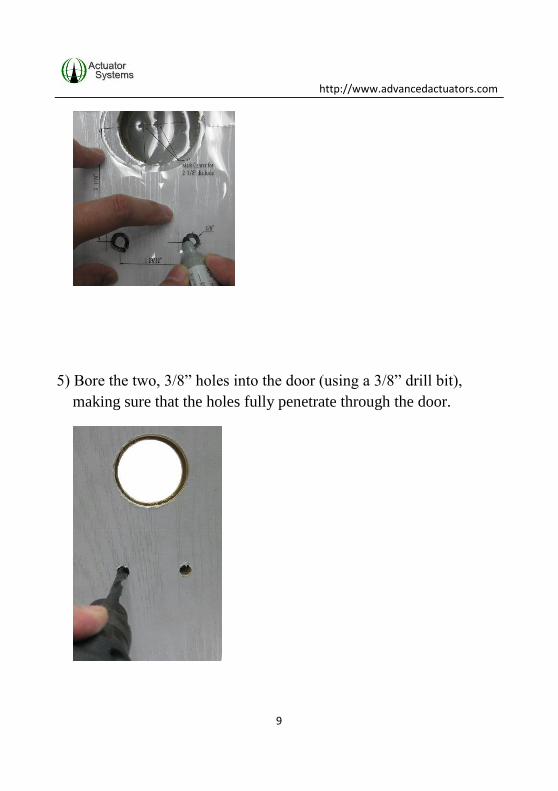
3) Rest the installation template on the front of the door, on top of the
existing 2 1/8” hole, making sure that it is aligned properly for the
door’s existing 2 3/8” or 2 ¾” backset.
4) Mark the two, 3/8” holes that you cut out of the installation
template on the door (with a magic marker).
http://www.advancedactuators.com
9
5) Bore the two, 3/8” holes into the door (using a 3/8” drill bit),
making sure that the holes fully penetrate through the door.
http://www.advancedactuators.com
10
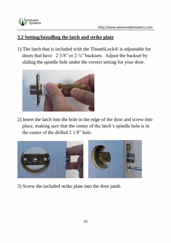
3.2 Setting/Installing the latch and strike plate
1) The latch that is included with the ThumbLock® is adjustable for
doors that have 2 3/8” or 2 ¾” backsets. Adjust the backset by
sliding the spindle hole under the correct setting for your door.
2) Insert the latch into the hole in the edge of the door and screw into
place, making sure that the center of the latch’s spindle hole is in
the center of the drilled 2 1/8” hole.
3) Screw the included strike plate into the door jamb.

http://www.advancedactuators.com
11
3.3 Removing handles and re-installing for Right/Left handed
configuration
1) The ThumbLock® is a non-handed lock, meaning that it can be
installed on either a right handed or left handed door.
2) Use the following steps to install the handles:
2a) Insert outside units’ handle onto the lock based on your
right/left handed configuration.

http://www.advancedactuators.com
12
2b) Turn the outside unit over and insert a long, thin Phillips
head screwdriver into the spindle hole.
2c) Fasten the screw, so the handle is firmly held in place.

http://www.advancedactuators.com
13
2d) Follow steps 2a thru 2c for installation of the handle on
the inside unit.
http://www.advancedactuators.com
14
Section 4 Installation
NOTE: Measure the exact thickness of the door and choose the
pre-labeled bag of screws (included) whose length matches the
exact thickness of the door. The pre-labeled bag of screws will be
needed in Section 4.4.
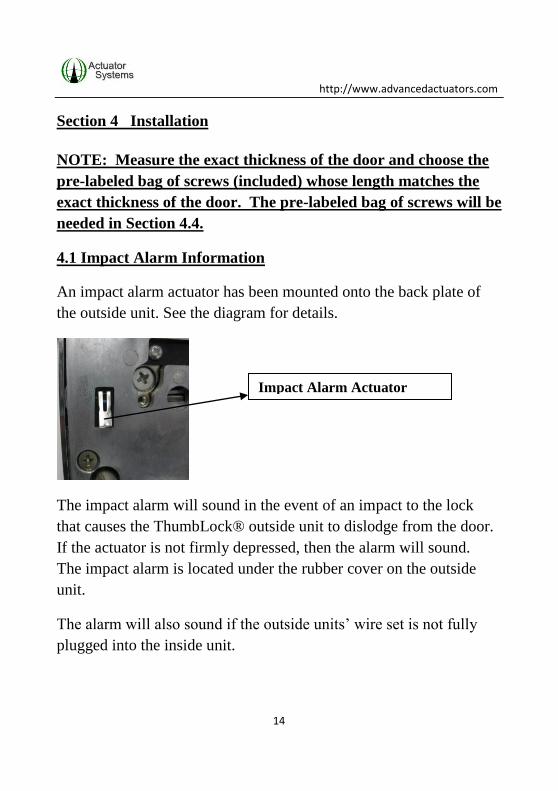
4.1 Impact Alarm Information
An impact alarm actuator has been mounted onto the back plate of
the outside unit. See the diagram for details.
The impact alarm will sound in the event of an impact to the lock
that causes the ThumbLock® outside unit to dislodge from the door.
If the actuator is not firmly depressed, then the alarm will sound.
The impact alarm is located under the rubber cover on the outside
unit.
The alarm will also sound if the outside units’ wire set is not fully
plugged into the inside unit.
Impact Alarm Actuator

http://www.advancedactuators.com
15
If the alarm is triggered, make sure to check the door and the lock
immediately. If there is no emergency occurring, then remove the
batteries to stop the alarm and check connections.
Do not install batteries until installation is completed and lock is
installed securely on the door.
4.2 Installing the Outside Unit
1) Attach the rubber gasket to the back of the outdoor unit.
2) Turn the outside unit over to make sure that the spindle hole is
perfectly square and not angled.

http://www.advancedactuators.com
16
3) Feed the wire set underneath the latch.
4) Align the two middle fixing posts with the two corresponding
holes in the latch.
http://www.advancedactuators.com
17
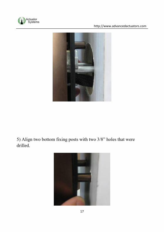
5) Align two bottom fixing posts with two 3/8” holes that were
drilled.
http://www.advancedactuators.com
18
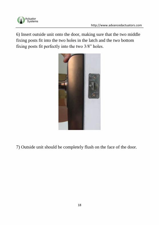
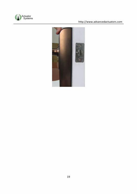
6) Insert outside unit onto the door, making sure that the two middle
fixing posts fit into the two holes in the latch and the two bottom
fixing posts fit perfectly into the two 3/8” holes.
7) Outside unit should be completely flush on the face of the door.
http://www.advancedactuators.com
19

http://www.advancedactuators.com
20
4.3 Installing the fixing plate
The purpose of the fixing plate is to securely fasten the outside unit
onto the door, so installation of the inside unit will be easier,
requiring only one person.
1) Place fixing plate over the 2 1/8” hole on the inside of the door.
2) Align center hole of the fixing plate with the spindle hole of the
latch.
3) Be sure that large rounded half circle is facing down on the fixing
plate (wire set goes thru large rounded half circle) and that the two
side screw holes are indented.
4) Screw the fixing plate onto the door, so it is secure. DO NOT
over tighten the screws.
http://www.advancedactuators.com
21
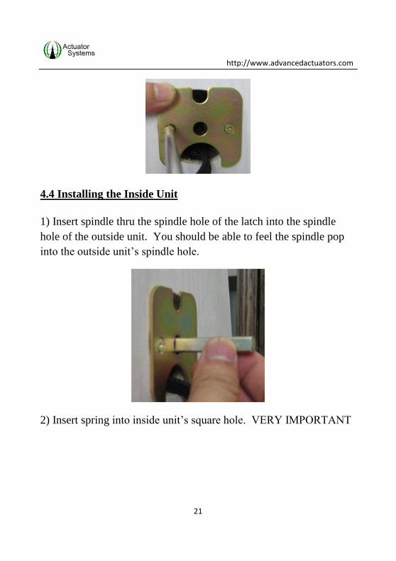
4.4 Installing the Inside Unit
1) Insert spindle thru the spindle hole of the latch into the spindle
hole of the outside unit. You should be able to feel the spindle pop
into the outside unit’s spindle hole.
2) Insert spring into inside unit’s square hole. VERY IMPORTANT

http://www.advancedactuators.com
22
3) Attach rubber gasket onto the inside unit.

http://www.advancedactuators.com
23
4) Plug the wire set (making sure black marker is on top of the
connector head) into plug on the inside unit. Be sure that wire set is
fully plugged and seated well.
5) Stuff excess wires into the 2 1/8” hole.
6) Install inside unit onto door, making sure that the spring does not
fall out when unit is placed upright and onto the spindle.

http://www.advancedactuators.com
24
7) Affix lock to the door with the three screws that match the
thickness of the door (per NOTE in beginning of Section 4). The
longer screw is for the top fixing post and the two shorter screws are
for the bottom fixing posts.
http://www.advancedactuators.com
25

http://www.advancedactuators.com
26
Section 5 Power Options
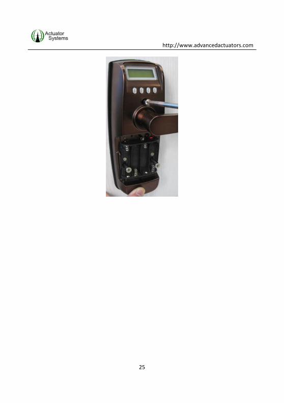
5.1 AA Batteries
1) Remove battery cover
2) Insert 4 AA batteries into the battery pack located on the inside
unit. We recommend Lithium AA batteries for longevity.

http://www.advancedactuators.com
27
3) When batteries are inserted, two beeps are heard indicating that
the lock is ready to program.
5.2 Hardwiring the ThumbLock®
It is possible to hard wire the ThumbLock® to an external 6 to
12VDC/1.2 amp power supply for constant power.
IMPORTANT:
WHEN THE THUMBLOCK® IS HARD WIRED, THE
AA BATTERIES CAN BE LEFT IN THE BATTERY
PACK FOR BACK UP POWER.
Only licensed electricians should hard wire the unit. BioAxxis
Development Corporation will not be held liable for faulty
hardwiring.
http://www.advancedactuators.com
28
ThumbLock® Operations Manual
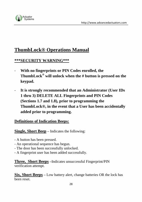
***SECURITY WARNING***
- With no fingerprints or PIN Codes enrolled, the
ThumbLock® will unlock when the # button is pressed on the
keypad.
- It is strongly recommended that an Administrator (User IDs
1 thru 3) DELETE ALL Fingerprints and PIN Codes
(Sections 1.7 and 1.8), prior to programming the
ThumbLock®, in the event that a User has been accidentally
added prior to programming.
Definitions of Indication Beeps:
Single, Short Beep – Indicates the following:
- A button has been pressed.
- An operational sequence has begun.
- The door has been successfully unlocked.
- A fingerprint user has been added successfully.
Three, Short Beeps –Indicates unsuccessful Fingerprint/PIN
verification attempt.
Six, Short Beeps – Low battery alert, change batteries OR the lock has
been reset.
http://www.advancedactuators.com
29
Definitions of LED
Red LED – Indicates any unsuccessful fingerprint/PIN verification
attempt.
Green LED – Indicates any successful fingerprint/PIN verification
attempt.
http://www.advancedactuators.com
30
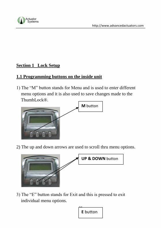
Section 1 Lock Setup
1.1 Programming buttons on the inside unit
1) The “M” button stands for Menu and is used to enter different
menu options and it is also used to save changes made to the
ThumbLock®.
2) The up and down arrows are used to scroll thru menu options.
3) The “E” button stands for Exit and this is pressed to exit
individual menu options.
M button
UP & DOWN button
E button

http://www.advancedactuators.com
31
NOTE: The following LOCK SETUP instructions are assuming
that there are no fingerprints enrolled in the ThumbLock®. All
LOCK SETUP functions can be done prior to enrolling an
Administrator fingerprint.
If changes are being made to the LOCK SETUP (or any other
menu options for that matter) after an Administrator fingerprint
has been enrolled, then their fingerprint will need to be verified
after pressing “M” to enter the menu options.
http://www.advancedactuators.com
32
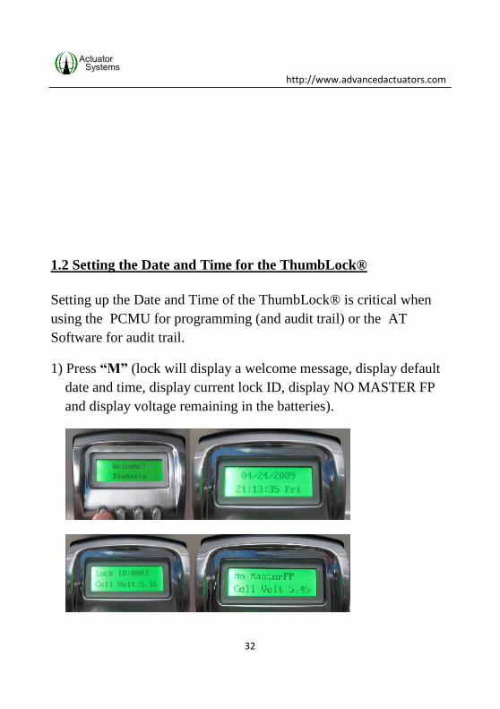
1.2 Setting the Date and Time for the ThumbLock®
Setting up the Date and Time of the ThumbLock® is critical when
using the PCMU for programming (and audit trail) or the AT
Software for audit trail.
1) Press “M” (lock will display a welcome message, display default
date and time, display current lock ID, display NO MASTER FP
and display voltage remaining in the batteries).
http://www.advancedactuators.com
33
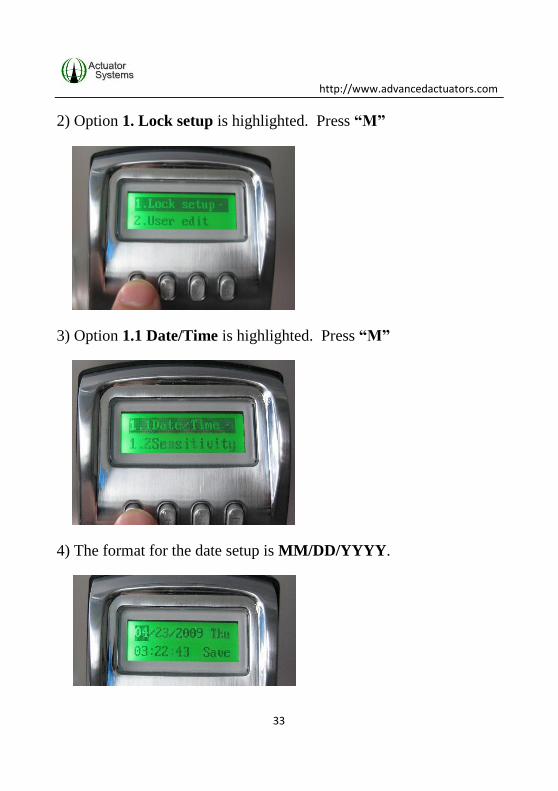
2) Option 1. Lock setup is highlighted. Press “M”
3) Option 1.1 Date/Time is highlighted. Press “M”
4) The format for the date setup is MM/DD/YYYY.
http://www.advancedactuators.com
34
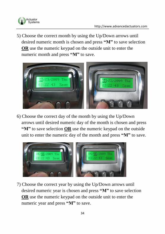
5) Choose the correct month by using the Up/Down arrows until
desired numeric month is chosen and press “M” to save selection
OR use the numeric keypad on the outside unit to enter the
numeric month and press “M” to save.
6) Choose the correct day of the month by using the Up/Down
arrows until desired numeric day of the month is chosen and press
“M” to save selection OR use the numeric keypad on the outside
unit to enter the numeric day of the month and press “M” to save.
7) Choose the correct year by using the Up/Down arrows until
desired numeric year is chosen and press “M” to save selection
OR use the numeric keypad on the outside unit to enter the
numeric year and press “M” to save.

http://www.advancedactuators.com
35
8) The format of the time setup is HH:MM:SS and is in MILITARY
TIME, meaning that the clock is 24 hours, instead of 12 hours.
EX: If it is 11:00 PM, the clock should be set up as 23:00:00.
9) Choose the correct hour by using the Up/Down arrows until
desired numeric hour is chosen and press “M” to save selection
OR use the numeric keypad on the outside unit to enter the
numeric hour and press “M” to save.
http://www.advancedactuators.com
36
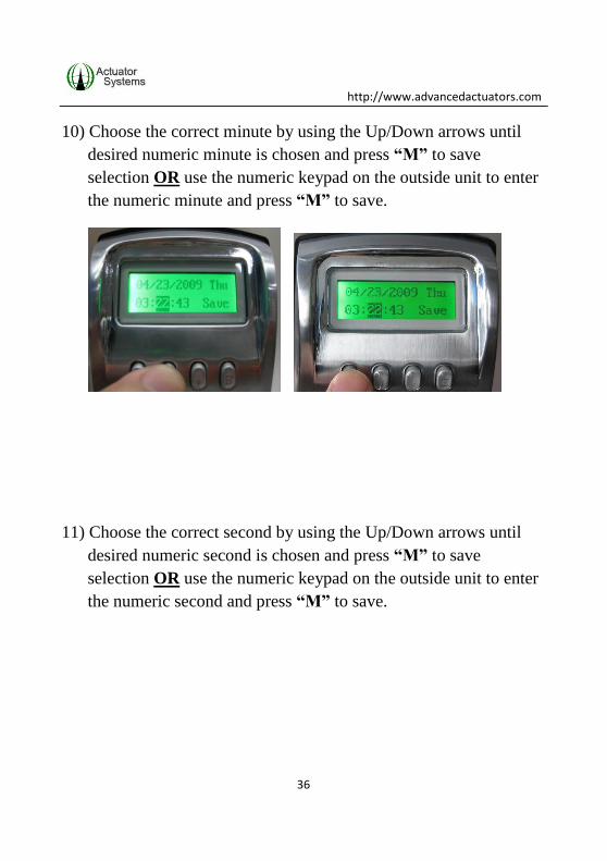
10) Choose the correct minute by using the Up/Down arrows until
desired numeric minute is chosen and press “M” to save
selection OR use the numeric keypad on the outside unit to enter
the numeric minute and press “M” to save.
11) Choose the correct second by using the Up/Down arrows until
desired numeric second is chosen and press “M” to save
selection OR use the numeric keypad on the outside unit to enter
the numeric second and press “M” to save.
http://www.advancedactuators.com
37
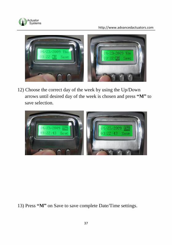
12) Choose the correct day of the week by using the Up/Down
arrows until desired day of the week is chosen and press “M” to
save selection.
13) Press “M” on Save to save complete Date/Time settings.

http://www.advancedactuators.com
38
14) “Saved” displays on LCD.
15) Press “E” to exit.

http://www.advancedactuators.com
39
1.3 Setting Fingerprint Sensitivity for the ThumbLock®
NOTE:
- Fingerprint sensitivity settings range from 1 to 9. Setting 1 is
the most strict setting, meaning that quality of fingerprint and
placement of fingerprint need to be almost perfect. Setting 9 is
the least stringent setting in regards to fingerprint quality and
placement.
- FALSE ACCEPTANCE RATE WILL INCREASE IF
SENSITIVITY LEVEL IS RAISED TO LEVEL 8 or 9.
1) In the Lock setup menu, scroll down to and highlight option 1.2
Sensitivity and press “M”.

http://www.advancedactuators.com
40
2) Use the up and down arrows to scroll thru the sensitivity levels
until the desired level is reached and press “M” to save setting.
3) Message “Sensitivity Saved” will display.
4) Press “E” to exit.
http://www.advancedactuators.com
41
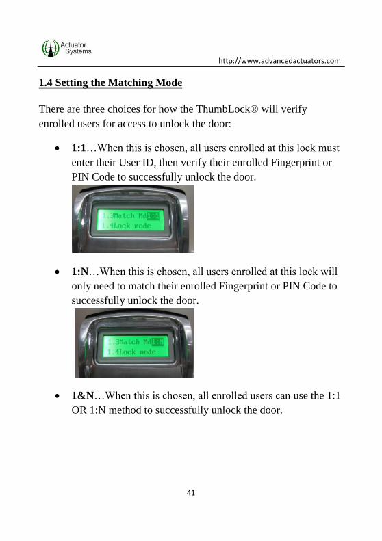
1.4 Setting the Matching Mode
There are three choices for how the ThumbLock® will verify
enrolled users for access to unlock the door:
1:1…When this is chosen, all users enrolled at this lock must
enter their User ID, then verify their enrolled Fingerprint or
PIN Code to successfully unlock the door.
1:N…When this is chosen, all users enrolled at this lock will
only need to match their enrolled Fingerprint or PIN Code to
successfully unlock the door.
1&N…When this is chosen, all enrolled users can use the 1:1
OR 1:N method to successfully unlock the door.

http://www.advancedactuators.com
42
Use the following steps to set up the Matching Mode at the
ThumbLock®:
1) In the Lock setup menu, scroll down to and highlight option 1.3
Match Mode and press “M”.
2) Use the up and down arrows to scroll thru the matching modes
until the desired mode is reached and press “M” to save setting.
3) Message “Match Mode Saved” will display.

http://www.advancedactuators.com
43
4) Press “E” to exit.
1.5 Setting the Lock Mode
There are two choices in the Lock Mode menu:
Auto – Also known as Auto-Lock, when this mode is enabled,
the ThumbLock® requires an enrolled fingerprint or PIN
Code to be verified to unlock the door.
TUM – TUM stands for Temporary Unlocked Mode. When
this is enabled, the solenoid will engage and the
ThumbLock® will stay unlocked, until an Administrator sets
the lock back to Auto-Lock mode.
http://www.advancedactuators.com
44
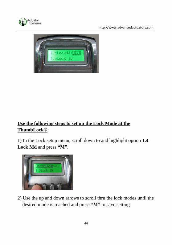
Use the following steps to set up the Lock Mode at the
ThumbLock®:
1) In the Lock setup menu, scroll down to and highlight option 1.4
Lock Md and press “M”.
2) Use the up and down arrows to scroll thru the lock modes until the
desired mode is reached and press “M” to save setting.

http://www.advancedactuators.com
45
3) Message “Lock Mode Saved” will display and there will be an
audible buzz of the solenoid engaging (if TUM is chosen) or
disengaging (if Auto is chosen).
4) Press “E” to exit.
1.6 Setting up the Lock ID
Setting up the Lock ID of the ThumbLock® is critical when using
the PCMU for programming (and audit trail) or the AT Software for
audit trail.
Use the following steps to set up the Lock ID at the
ThumbLock®:
1) In the Lock setup menu, scroll down to and highlight option 1.5
Lock ID and press “M”.

http://www.advancedactuators.com
46
2) Use the up and down arrows to scroll to the desired lock ID OR
use the numeric keypad on the outside unit to enter the desired
lock ID and press “M” to save setting.
3) Message “Lock ID Saved” will display.

http://www.advancedactuators.com
47
4) Press “E” to exit.

http://www.advancedactuators.com
48
1.7 Deleting ALL Fingerprints in the ThumbLock®
1) In the Lock setup menu, scroll down to and highlight option 1.6
Clear FP & PIN and press “M”.
2) To delete all fingerprints, highlight the Fingerprints option and
press “M”.
http://www.advancedactuators.com
49
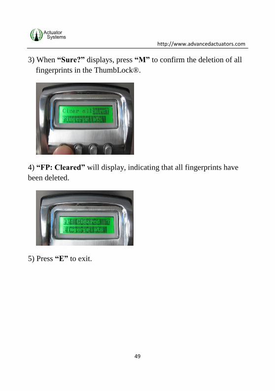
3) When “Sure?” displays, press “M” to confirm the deletion of all
fingerprints in the ThumbLock®.
4) “FP: Cleared” will display, indicating that all fingerprints have
been deleted.
5) Press “E” to exit.
http://www.advancedactuators.com
50
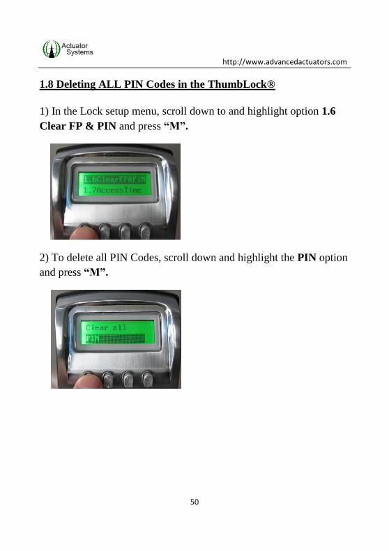
1.8 Deleting ALL PIN Codes in the ThumbLock®
1) In the Lock setup menu, scroll down to and highlight option 1.6
Clear FP & PIN and press “M”.
2) To delete all PIN Codes, scroll down and highlight the PIN option
and press “M”.

http://www.advancedactuators.com
51
3) When “Sure?” displays, press “M” to confirm the deletion of all
PIN Codes in the ThumbLock®.
4) “PIN: ClPIN” will display, indicating that all PIN Codes have
been deleted.
5) Press “E” to exit.

http://www.advancedactuators.com
52
1.9 Setting up Timed Access for the ThumbLock®
The ThumbLock® has three TIME MODES that may be chosen for
the lock:
ANY TIME…When this is chosen, the specific lock allows
for all enrolled Users to have access to unlock the door. The
exception to this is if specific Timed Access is set up for
individual Users.
INVALID…This can also be called lock down mode. When
this is enabled, only Administrators for the specific lock will
have access to unlock the door.

http://www.advancedactuators.com
53
ACC-TIME…This mode allows for timed access to the lock
to be created for a specific date range, days of the week and
time frame within the days of the week. Acc-Time means
Access Time.
NOTE: The Time Setting chosen/created for the lock will
override any specific Timed Access assigned for a specific User.
For example, if ACC-TIME is chosen for the lock and set to Mon,
Wed and Fri 9am to 5pm, Users will only have access to unlock
the door during the set days and times, no matter what
individual timed access was set for them. However,
Administrators (User ID 1-3) will always have access to unlock
the ThumbLock®.

http://www.advancedactuators.com
54
1.10 Choosing “ANY TIME” as the Access mode for the
ThumbLock®
1) In the Lock setup menu, scroll down to and highlight option 1.7
Access Time and press “M”.
2) Scroll to “ANYTIME” option and press “M”.
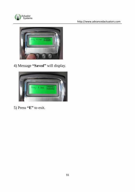
3) “Save” is highlighted. Press “M”
http://www.advancedactuators.com
55
4) Message “Saved” will display.
5) Press “E” to exit.
http://www.advancedactuators.com
56
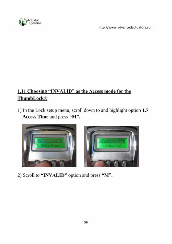
1.11 Choosing “INVALID” as the Access mode for the
ThumbLock®
1) In the Lock setup menu, scroll down to and highlight option 1.7
Access Time and press “M”.
2) Scroll to “INVALID” option and press “M”.

http://www.advancedactuators.com
57
3) “Save” is highlighted. Press “M”
4) Message “Saved” will display.
5) Press “E” to exit.
http://www.advancedactuators.com
58
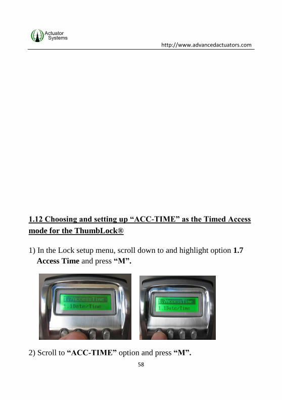
1.12 Choosing and setting up “ACC-TIME” as the Timed Access
mode for the ThumbLock®
1) In the Lock setup menu, scroll down to and highlight option 1.7
Access Time and press “M”.
2) Scroll to “ACC-TIME” option and press “M”.

http://www.advancedactuators.com
59
3) “Save” is highlighted. Press “M”
4) Message “Saved” will display.
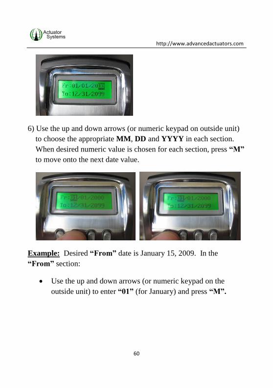
5) The “From” and “To” Date Range options display. The format
for the Date Range settings are MMDDYYYY (from left to right).
http://www.advancedactuators.com
60
6) Use the up and down arrows (or numeric keypad on outside unit)
to choose the appropriate MM, DD and YYYY in each section.
When desired numeric value is chosen for each section, press “M”
to move onto the next date value.
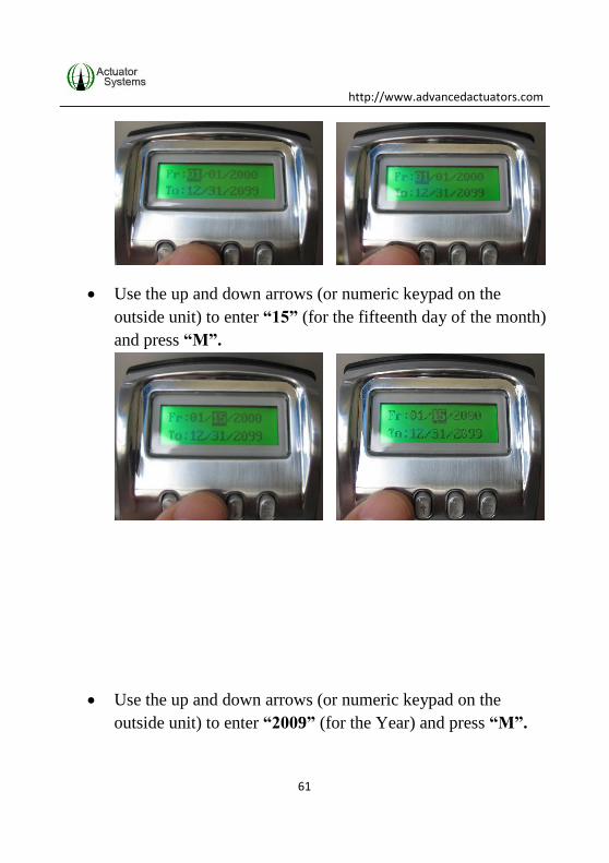
Example: Desired “From” date is January 15, 2009. In the
“From” section:
Use the up and down arrows (or numeric keypad on the
outside unit) to enter “01” (for January) and press “M”.
http://www.advancedactuators.com
61
Use the up and down arrows (or numeric keypad on the
outside unit) to enter “15” (for the fifteenth day of the month)
and press “M”.
Use the up and down arrows (or numeric keypad on the
outside unit) to enter “2009” (for the Year) and press “M”.

http://www.advancedactuators.com
62
Use the same steps for the “To” date.
7) Once the Date Range is set up the Time Frame and Days of the
Week will display.
8) Use the following steps to set up the Time Frame for the
ThumbLock®:
http://www.advancedactuators.com
63
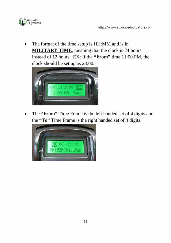
The format of the time setup is HH:MM and is in
MILITARY TIME, meaning that the clock is 24 hours,
instead of 12 hours. EX: If the “From” time 11:00 PM, the
clock should be set up as 23:00.
The “From” Time Frame is the left handed set of 4 digits and
the “To” Time Frame is the right handed set of 4 digits.

http://www.advancedactuators.com
64
Choose the correct “From” hour by using the Up/Down
arrows until desired numeric hour is chosen and press “M” to
save selection OR use the numeric keypad on the outside unit
to enter the numeric hour and press “M” to save.
Choose the correct “From” minute by using the Up/Down
arrows until desired numeric minute is chosen and press “M”
to save selection OR use the numeric keypad on the outside
unit to enter the numeric minute and press “M” to save.
http://www.advancedactuators.com
65
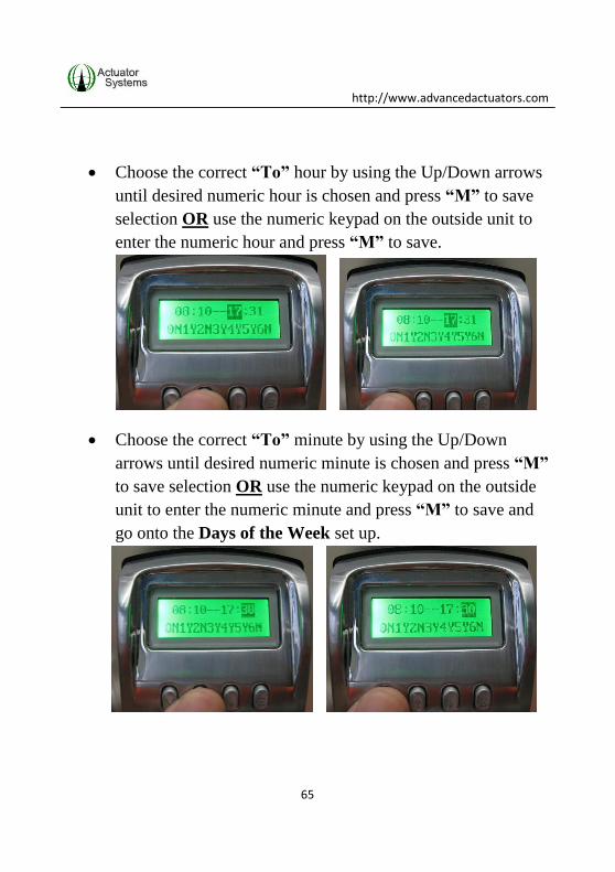
Choose the correct “To” hour by using the Up/Down arrows
until desired numeric hour is chosen and press “M” to save
selection OR use the numeric keypad on the outside unit to
enter the numeric hour and press “M” to save.
Choose the correct “To” minute by using the Up/Down
arrows until desired numeric minute is chosen and press “M”
to save selection OR use the numeric keypad on the outside
unit to enter the numeric minute and press “M” to save and
go onto the Days of the Week set up.

http://www.advancedactuators.com
66
9) Use the following steps to set up the Days of the Week access for
the ThumbLock®:
Each number corresponds with a day of the week:
0= Sunday
1= Monday
2= Tuesday
3= Wednesday
4= Thursday
5= Friday
6= Saturday
Press the Up and Down arrows to choose “Y” (Yes) OR “N”
(No) for each day of the week that is highlighted.

http://www.advancedactuators.com
67
If “Y” (Yes) is chosen for a specific day of the week, then all
enrolled Users (that do not have Acc-Times set up for their
specific individual User ID) will have access to unlock the
ThumbLock®, on that day of the week, during the Date
Range and Time Frame that has already been set up. Once
the Date Range or Time Frame has expired, all enrolled Users
will not be able to unlock the ThumbLock®. Only
Administrators (User ID 1-3) will have access to unlock the
ThumbLock®.
If “N” (No) is chosen for a specific day of the week, then no
enrolled Users will have access to unlock the ThumbLock®
for that day of the week. Only Administrators (User ID 1-3)
will have access to unlock the ThumbLock®.
Press “M” to move onto the next day of the week.

http://www.advancedactuators.com
68
When setting for day of the week “6” (Saturday) is
completed, press “M”.
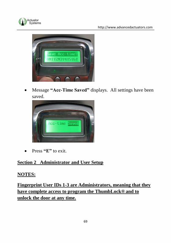
Message “Save Acc-Time?” displays. Press “M”
http://www.advancedactuators.com
69
Message “Acc-Time Saved” displays. All settings have been
saved.
Press “E” to exit.
Section 2 Administrator and User Setup
NOTES:
Fingerprint User IDs 1-3 are Administrators, meaning that they
have complete access to program the ThumbLock® and to
unlock the door at any time.
http://www.advancedactuators.com
70
To access any menu options, after an Administrator fingerprint
has been enrolled, the Administrator’s fingerprint will need to be
verified after pressing “M” to enter the menu options.
The term “Fingerprint” is used as a general term when
describing fingers or thumbs to use for enrollment/verification.
Before enrolling and verifying fingerprints, make sure to read the
following helpful hints for Fingerprint Enrollment and
Verification:
Generally, the center of the vortex (swirl) of the fingerprint pattern is
the key data point; ideally, it is placed in the center of the sensor’s
glass window in a consistent way. Your finger or thumb should
be flat, motionless and held with light pressure in the same way
each time. See the picture below for some guiding drawings.
Also, be sure that your fingerprint is well defined, where you can
visibly see the well defined peaks and valleys of the vortex ridge
pattern.
Light pressure when placing the finger or thumb on the scanner gives
the best image, but the finger must not move during scanning.
Adjust Fingerprint Sensitivity settings per Section 1.3.
Moist fingers and thumbs give better images than dry ones. If on cold,
dry days you have difficulty, for example, try moistening your finger
or thumb with your breath or a little lotion.

http://www.advancedactuators.com
71
Very dry, dirty, fingerprints with cracks going across them or scarred
fingers/thumbs are obviously not recommended, since they will
obscure the fingerprint.
Always wait until the fingerprint scanner turns on to place your
finger/thumb on the scanning window. This is true for both
fingerprint enrollment AND verification.
When trying to enroll or verify fingerprints in direct sunlight, be sure
to shade the sensor with your shadow, so sunlight will not reflect off
of the mirror in the sensor.

http://www.advancedactuators.com
72
2.1 Creating, Editing & Deleting User Access
1) Press “M” (lock will display a welcome message, display date and
time, display current lock ID, display NO MASTER FP and
display voltage remaining in the batteries).
If an Administrator has already been added to the lock, the
Administrator will need to successfully verify their enrolled
fingerprint after pressing “M”.

http://www.advancedactuators.com
73
2) Option 2. User edit is highlighted. Press “M”
3) In the ID: field, use the up and down arrows to scroll to the
desired User ID OR use the numeric keypad on the outside unit to
enter the User ID and press “M”.

http://www.advancedactuators.com
74
Again, User IDs 1 thru 3 are Administrator (Master) Users
that will have access at any time to unlock the door or
program the ThumbLock®. Users 4 thru 1000 are General
Users that have access to unlock the door at times set up by
one of the Administrator Users and have no programming
rights to the ThumbLock®.
4) User Level of the User ID is highlighted (Master or User). If
desired, use the up and down arrow to change User Level for the
specific User ID and Press “M”.
5) Use the down arrow to scroll thru the following options:
http://www.advancedactuators.com
75
2.1 Add – When this option is chosen, fingerprints can be
added for the specific User ID.
2.2 Del – When this option is chosen, the fingerprints
associated to the specific User ID will be deleted.
2.3 Pin – When this option is chosen, a PIN Code can be
created, changed or deleted for the specific User ID.
2.4 Access Time – When this option is chosen, it allows for
timed access to be created for a specific date range, days of
the week and time frame within the days of the week for the
Specific User ID. Again, any Acc-Time settings that were
previously made for the LOCK, will override any Access
Time settings for the specific User ID.
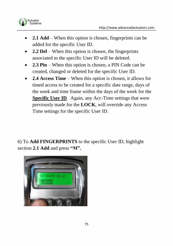
6) To Add FINGERPRINTS to the specific User ID, highlight
section 2.1 Add and press “M”.
http://www.advancedactuators.com
76
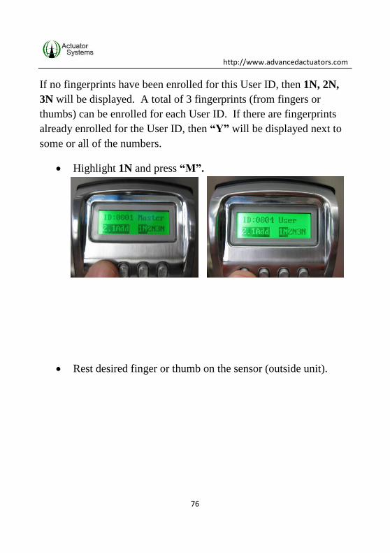
If no fingerprints have been enrolled for this User ID, then 1N, 2N,
3N will be displayed. A total of 3 fingerprints (from fingers or
thumbs) can be enrolled for each User ID. If there are fingerprints
already enrolled for the User ID, then “Y” will be displayed next to
some or all of the numbers.
Highlight 1N and press “M”.
Rest desired finger or thumb on the sensor (outside unit).

http://www.advancedactuators.com
77
Keep finger or thumb on the sensor while it flashes three
quick times. KEEP FINGERPRINT STILL DURING
SCANNING.
If finger/thumb “1” was successfully enrolled, a single short
beep will be heard, the LCD will display “Success” and 1N
will change to 1Y.

http://www.advancedactuators.com
78
o If unsuccessful, “Failed” will display on the LCD and
1N will not change to 1Y. Repeat the steps above to
try again.
NOTE: If desired, the same finger/thumb can also be used
for fingers/thumbs “2” and “3”. This is recommended for
Users with poor quality fingerprints. However, different
fingers/thumbs can be used for fingers/thumbs 1, 2 &3.
Press the up arrow to highlight 2N and press “M”.
Rest the next (or same) desired finger or thumb on the sensor
(outside unit).
http://www.advancedactuators.com
79
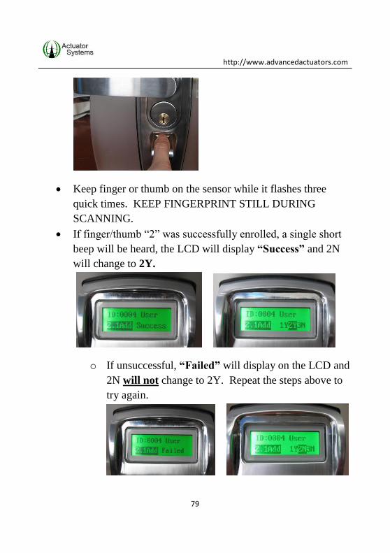
Keep finger or thumb on the sensor while it flashes three
quick times. KEEP FINGERPRINT STILL DURING
SCANNING.
If finger/thumb “2” was successfully enrolled, a single short
beep will be heard, the LCD will display “Success” and 2N
will change to 2Y.
o If unsuccessful, “Failed” will display on the LCD and
2N will not change to 2Y. Repeat the steps above to
try again.
http://www.advancedactuators.com
80
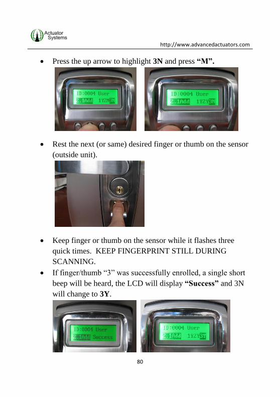
Press the up arrow to highlight 3N and press “M”.
Rest the next (or same) desired finger or thumb on the sensor
(outside unit).
Keep finger or thumb on the sensor while it flashes three
quick times. KEEP FINGERPRINT STILL DURING
SCANNING.
If finger/thumb “3” was successfully enrolled, a single short
beep will be heard, the LCD will display “Success” and 3N
will change to 3Y.
http://www.advancedactuators.com
81
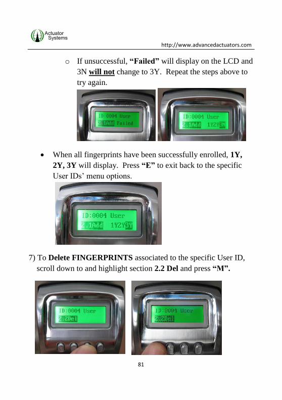
o If unsuccessful, “Failed” will display on the LCD and
3N will not change to 3Y. Repeat the steps above to
try again.
When all fingerprints have been successfully enrolled, 1Y,
2Y, 3Y will display. Press “E” to exit back to the specific
User IDs’ menu options.
7) To Delete FINGERPRINTS associated to the specific User ID,
scroll down to and highlight section 2.2 Del and press “M”.

http://www.advancedactuators.com
82
“Del?” message will display. Press “M” to complete
deletion of fingerprints associated to the specific User ID.
“Deleted” message will display
You will be returned to menu option 2.2 Del.
NOTE: Once deletion of fingerprints associated to the specific
User ID is complete, fingerprints can be re-enrolled for the
specific User ID (follow step 6 above).

http://www.advancedactuators.com
83
8) To Add or Modify a PIN CODE associated to the specific User
ID, scroll down to and highlight section 2.3 Pin and press “M”.
Using the numeric pad on the outside unit, enter a 1 to 10
digit PIN Code for the specific User ID (all User IDs can
have both a PIN Code and/or Fingerprints assigned to them)
and Press “M”.
http://www.advancedactuators.com
84
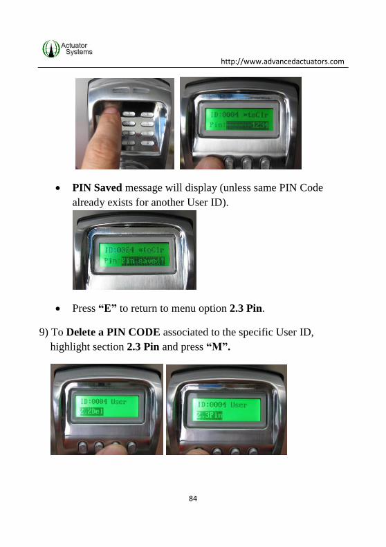
PIN Saved message will display (unless same PIN Code
already exists for another User ID).
Press “E” to return to menu option 2.3 Pin.
9) To Delete a PIN CODE associated to the specific User ID,
highlight section 2.3 Pin and press “M”.

http://www.advancedactuators.com
85
Using the numeric pad on the outside unit, press the * button
(clears PIN Code) and Press “M”.
PIN Saved message will display (even though it has been
deleted).
Press “E” to return to menu option 2.3 Pin.
10) To set up Timed Access for the Specific User ID, scroll down to
and highlight section 2.4 Access Time and press “M”.

http://www.advancedactuators.com
86
Each specific USER ID has three TIME MODES that can be set up
for them (Administrators can edit each specific User IDs Timed
Access at anytime):
ANY TIME…When this is chosen, the specific User ID can
unlock the door with their enrolled fingerprints or PIN Codes
at any time. The exception to this is if specific Timed Access
is set up for the LOCK.
INVALID…This can also be called lock down mode for the
specific User ID. When this is enabled for the specific User
ID, the User will not be able to unlock the door with their
enrolled fingerprints or PIN Codes, until an Administrator re-
assigns them to ANYTIME or ACC-TIME.
ACC-TIME…This mode allows for specific User ID to have
timed access to unlock the ThumbLock® with their enrolled
fingerprints or PIN Codes during a specific date range, days
of the week and time frame within the days of the week.
Acc-Time means Access Time.
http://www.advancedactuators.com
87
NOTE: The Time Setting chosen/created for the lock will
override any specific Timed Access assigned for a specific User.
For example, if ACC-TIME is chosen for the lock and set to Mon,
Wed and Fri 9am to 5pm, Users will only have access to unlock
the door during the set days and times, no matter what
individual timed access was set for them. However,
Administrators (User ID 1-3) will always have access to unlock
the ThumbLock®.
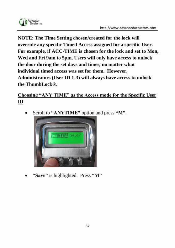
Choosing “ANY TIME” as the Access mode for the Specific User
ID
Scroll to “ANYTIME” option and press “M”.
“Save” is highlighted. Press “M”
http://www.advancedactuators.com
88
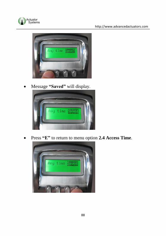
Message “Saved” will display.
Press “E” to return to menu option 2.4 Access Time.
http://www.advancedactuators.com
89
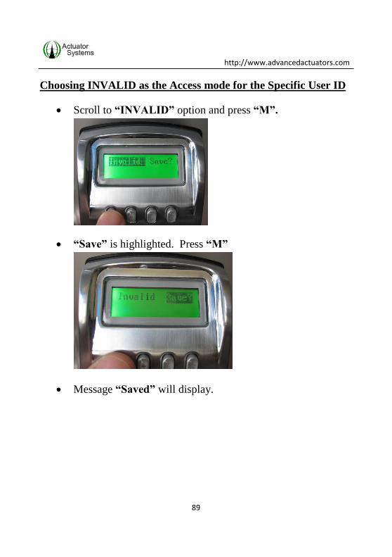
Choosing INVALID as the Access mode for the Specific User ID
Scroll to “INVALID” option and press “M”.
“Save” is highlighted. Press “M”
Message “Saved” will display.

http://www.advancedactuators.com
90
Press “E” to return to menu option 2.4 Access Time.
Choosing and setting up “ACC-TIME” as the Timed Access
mode for the Specific User ID
Scroll to “ACC-TIME” option and press “M”.

http://www.advancedactuators.com
91
“Save” is highlighted. Press “M”
Message “Saved” will display.
The “From” and “To” Date Range options display. The
format for the Date Range settings are MMDDYYYY (from
left to right).

http://www.advancedactuators.com
92
Use the up and down arrows (or numeric keypad on outside
unit) to choose the appropriate MM, DD and YYYY in each
section. When desired numeric value is chosen for each
section, press “M” to move onto the next date value.
o Example: Desired “From” date is January 15, 2009. In
the “From” section:
http://www.advancedactuators.com
93
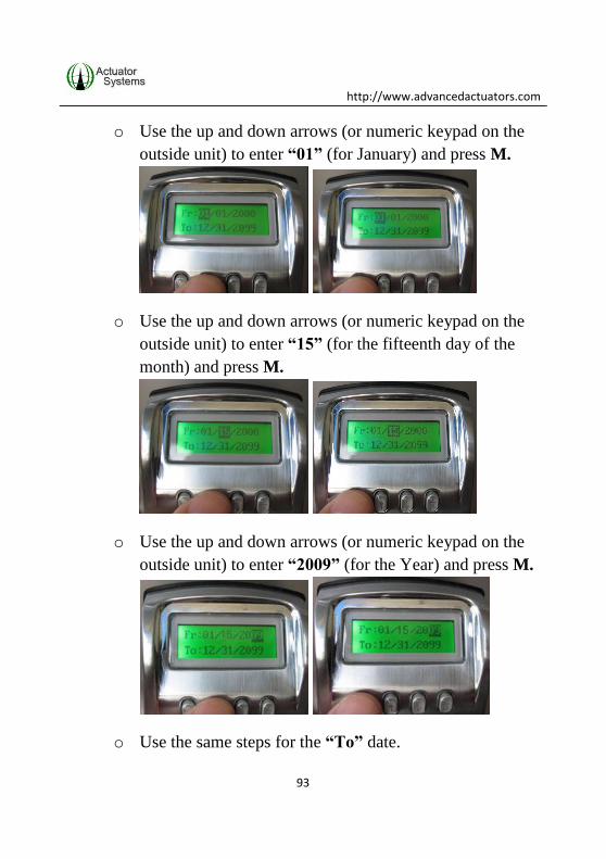
o Use the up and down arrows (or numeric keypad on the
outside unit) to enter “01” (for January) and press M.
o Use the up and down arrows (or numeric keypad on the
outside unit) to enter “15” (for the fifteenth day of the
month) and press M.
o Use the up and down arrows (or numeric keypad on the
outside unit) to enter “2009” (for the Year) and press M.
o Use the same steps for the “To” date.

http://www.advancedactuators.com
94
Once the Date Range is set up the Time Frame and Days of
the Week will display.
Use the following steps to set up the Time Frame for the Specific
User ID:
The format of the time setup is HH:MM and is in
MILITARY TIME, meaning that the clock is 24 hours,
instead of 12 hours. EX: If the “From” time 11:00 PM, the
clock should be set up as 23:00.
The “From” Time Frame is the left handed set of 4 digits and
the “To” Time Frame is the right handed set of 4 digits.

http://www.advancedactuators.com
95
Choose the correct “From” hour by using the Up/Down
arrows until desired numeric hour is chosen and press “M” to
save selection OR use the numeric keypad on the outside unit
to enter the numeric hour and press “M” to save.
Choose the correct “From” minute by using the Up/Down
arrows until desired numeric minute is chosen and press “M”
to save selection OR use the numeric keypad on the outside
unit to enter the numeric minute and press “M” to save.

http://www.advancedactuators.com
96
Choose the correct “To” hour by using the Up/Down arrows
until desired numeric hour is chosen and press “M” to save
selection OR use the numeric keypad on the outside unit to
enter the numeric hour and press “M” to save.
Choose the correct “To” minute by using the Up/Down
arrows until desired numeric minute is chosen and press “M”
to save selection OR use the numeric keypad on the outside
unit to enter the numeric minute and press “M” to save and
go onto the Days of the Week set up.

http://www.advancedactuators.com
97
Use the following steps to set up the Days of the Week access for
the Specific User ID:
Each number corresponds with a day of the week:
0= Sunday
1= Monday
2= Tuesday
3= Wednesday
4= Thursday
5= Friday
6= Saturday
Press the Up and Down arrows to choose “Y” (Yes) OR “N”
(No) for each day of the week that is highlighted.

http://www.advancedactuators.com
98
If “Y” (Yes) is chosen for a specific day of the week, then the
Specific User ID will have access to unlock the
ThumbLock® with their enrolled fingerprints and/or PIN
Code, on that day of the week, during the Date Range and
Time Frame that has already been set up. Once the Date
Range or Time Frame has expired, the fingerprints and PIN
Code associated to the Specific User ID will not be able to
unlock the ThumbLock®.
If “N” (No) is chosen for a specific day of the week, then the
enrolled fingerprints and/or PIN Code associated to the
specific User ID will not be able unlock the ThumbLock® for
that day of the week.
Press “M” to move onto the next day of the week.

http://www.advancedactuators.com
99
When setting for day of the week “6” (Saturday) is
completed, press “M”.
Message “Save Acc-Time?” displays. Press “M”
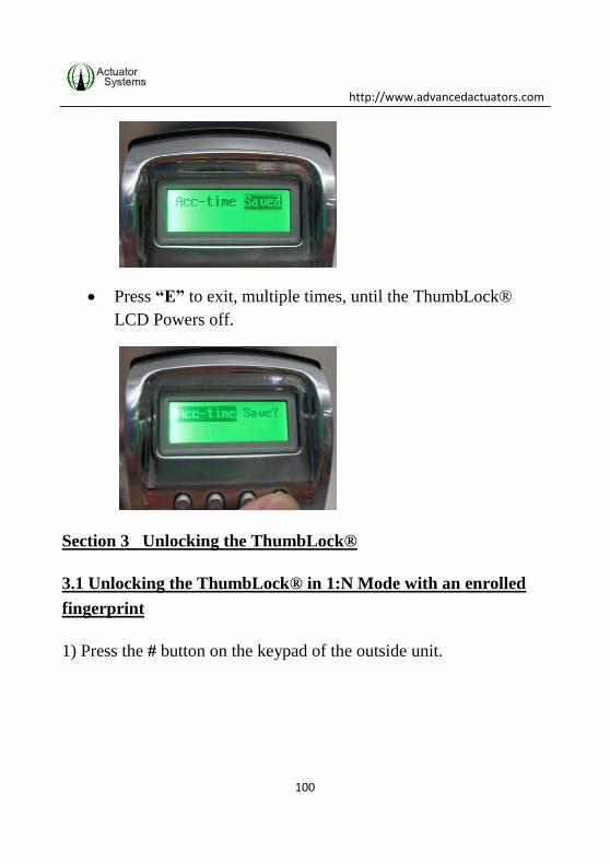
Message “Acc-Time Saved” displays. All settings have been
saved for the Specific User ID.
http://www.advancedactuators.com
100
Press “E” to exit, multiple times, until the ThumbLock®
LCD Powers off.
Section 3 Unlocking the ThumbLock®
3.1 Unlocking the ThumbLock® in 1:N Mode with an enrolled
fingerprint
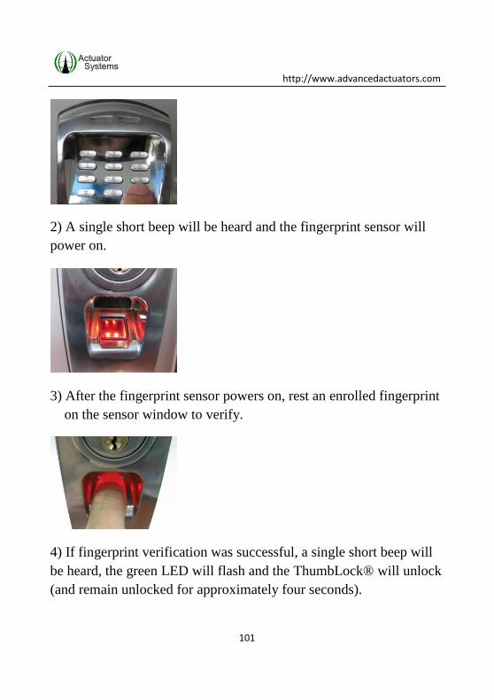
1) Press the # button on the keypad of the outside unit.
http://www.advancedactuators.com
101
2) A single short beep will be heard and the fingerprint sensor will
power on.
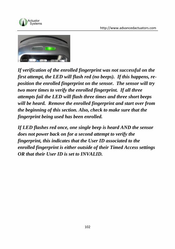
3) After the fingerprint sensor powers on, rest an enrolled fingerprint
on the sensor window to verify.
4) If fingerprint verification was successful, a single short beep will
be heard, the green LED will flash and the ThumbLock® will unlock
(and remain unlocked for approximately four seconds).
http://www.advancedactuators.com
102
If verification of the enrolled fingerprint was not successful on the
first attempt, the LED will flash red (no beeps). If this happens, re-
position the enrolled fingerprint on the sensor. The sensor will try
two more times to verify the enrolled fingerprint. If all three
attempts fail the LED will flash three times and three short beeps
will be heard. Remove the enrolled fingerprint and start over from
the beginning of this section. Also, check to make sure that the
fingerprint being used has been enrolled.
If LED flashes red once, one single beep is heard AND the sensor
does not power back on for a second attempt to verify the
fingerprint, this indicates that the User ID associated to the
enrolled fingerprint is either outside of their Timed Access settings
OR that their User ID is set to INVALID.

http://www.advancedactuators.com
103
3.2 Unlocking the ThumbLock® in 1:N Mode with a registered
PIN Code
1) Enter the registered PIN Code on the keypad of the outside unit
and press **.
2) If PIN Code verification was successful, a single short beep will
be heard, the green LED will flash and the ThumbLock® will unlock
(and remain unlocked for approximately four seconds).
If verification of the registered PIN Code was not successful, the
LED will flash three times, three short beeps will be heard and the
ThumbLock® will power off. Start over from the beginning of this
section. Also, check to make sure that the PIN Code being used has
been registered.
If LED flashes red once and one single beep is heard, this indicates
that the User ID associated to the registered PIN Code is either

http://www.advancedactuators.com
104
outside of the Timed Access settings OR that the User ID is set to
INVALID.
3.3 Unlocking the ThumbLock® in 1:1 Mode with an enrolled
fingerprint
1) Enter the specific User ID on the keypad of the outside unit,
followed by pressing the # button.
2) A single short beep will be heard and the fingerprint sensor will
power on.
3) After the fingerprint sensor powers on, rest the enrolled fingerprint
associated to the User ID on the sensor window to verify.

http://www.advancedactuators.com
105
4) If fingerprint verification was successful, a single short beep will
be heard, the green LED will flash and the ThumbLock® will
unlock (and remain unlocked for approximately four seconds).
If verification of the enrolled fingerprint was not successful on the
first attempt, the LED will flash red (no beeps). If this happens, re-
position the enrolled fingerprint on the sensor. The sensor will try
two more times to verify the enrolled fingerprint. If all three
attempts fail the LED will flash three times and three short beeps
will be heard. Remove the enrolled fingerprint and start over from
the beginning of this section. Also, check to make sure that the
fingerprint being used has been enrolled.
If LED flashes red once, one single beep is heard AND the sensor
does not power on, this indicates that the User ID associated to the
enrolled fingerprint is either outside of their Timed Access settings
OR that their User ID is set to INVALID.

http://www.advancedactuators.com
106
3.4 Unlocking the ThumbLock® in 1:1 Mode with a registered
PIN Code
1) Enter the specific User ID on the keypad of the outside unit, Press
*, Enter the Registered PIN Code and Press *.
2) If PIN Code verification was successful, a single short beep will
be heard, the green LED will flash and theThumbLock® will unlock
(and remain unlocked for approximately four seconds).
If verification of the registered PIN Code was not successful, the
LED will flash three times, three short beeps will be heard and
theThumbLock® will power off. Start over from the beginning of

http://www.advancedactuators.com
107
this section. Also, check to make sure that the PIN Code being used
has been registered.
If LED flashes red once and one single beep is heard, this indicates
that the User ID associated to the registered PIN Code is either
outside of the Timed Access settings OR that the User ID is set to
INVALID.
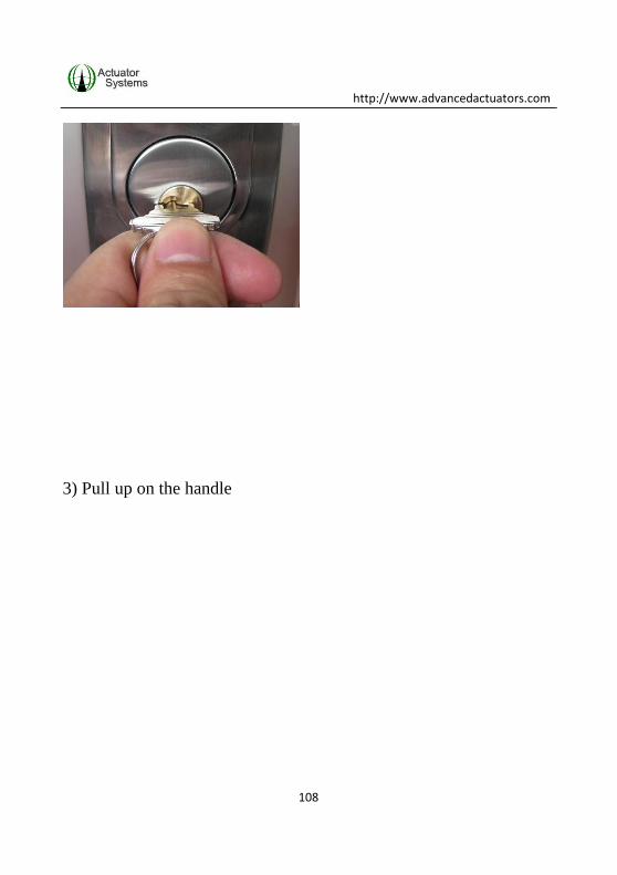
3.5 Unlocking theThumbLock® with the override keys
1) Insert key into the keyhole.
2) Turn the key in the RIGHT direction to horizontal level (90
degrees).
http://www.advancedactuators.com
108
3) Pull up on the handle
http://www.advancedactuators.com
109
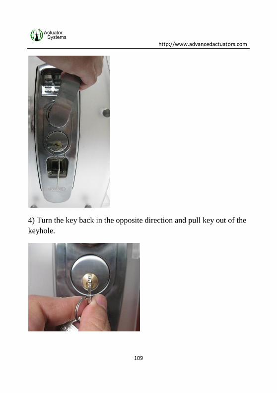
4) Turn the key back in the opposite direction and pull key out of the
keyhole.

http://www.advancedactuators.com
110
Support Information:
For warranty support please call Actuator Systems directly at 407-
567-7130 x102 OR e-mail [email protected].

http://www.advancedactuators.com
111
USER ENROLLMENT TABLE:
Number Hand (R or L) Finger Used PIN CODE Name

http://www.advancedactuators.com
112

http://www.advancedactuators.com
113

http://www.advancedactuators.com
114

http://www.advancedactuators.com
115

http://www.advancedactuators.com
116

http://www.advancedactuators.com
117

http://www.advancedactuators.com
118

http://www.advancedactuators.com
119

http://www.advancedactuators.com
120

http://www.advancedactuators.com
121

http://www.advancedactuators.com
122

http://www.advancedactuators.com
123

http://www.advancedactuators.com
124

http://www.advancedactuators.com
125

http://www.advancedactuators.com
126