biogas handbook - geichina.org
TRANSCRIPT

PR
EFA
CE
PREFACEIn line with the ever increasing price of energy, biomass
energy sources such as biogas have entered a new phase
of development. Household biogas technology has
enjoyed a period of rapid development, and the
technology is continuing to mature, with more varieties
and models developing, and the field of use becoming
ever wider. In order to assist more peasants to easily
choose an appropriate digester, this book has been
written as a reference to aid the comprehensive use of
biogas and its digesters.
This book features a systematic and detailed explanation
of the types and application environments of digesters,
construction and commissioning of digesters, use and
management of biogas, and the comprehensive holistic
use of gas.
This book is designed for farmers and friends interested
in using biogas
PR
EFA
CE

Glo
bal E
nvi
ron
men
tal In
stit
ute C
Con
tent
s
Application of Single Household Biogas Technology 06
Main Types of Household biogas Digester 10 Above Ground Plastic (polyethylene) Biodigester 12 Floating Drum Biodigester 15 Plastic Partially Submerged Digester 24 Fiberglass Reinforced Plastic (FRP) Partially Sumberged Digester 26
Use & Management of Household Digesters 30 Basic Operation Steps for Household Digesters 30 Management of Household Digesters 32 Installation and Use of Gas Lights & Stoves 38
Comprehensive Use of Household Biogas 40 Preservation of Fruit 40 Preventing Pests in Barns & Granaries 40 Preventing Pests in Containers 41 Soaking Seeds 42 Using Spent Slurry and Sediment as a Fertiliser 43 Supplementing Pig and Fish Food 44
Contents

05
CAppendix 1: Human and Animal Average Daily & Annual 45
Production & Recovery
Appendix 2: Relationship between fermentation time 45
and temperature
Appendix 3: Gas Production using the Semicontinuous 46
Fermentation Technique at Standard
Temperature Conditions
Appendix 4: Rate of Digestion with Common Input Types 46
Appendix 5: Chicken, Cow Manure Production in Pig 47
Equivalent
Appendix 6: GEI’s Biogas Demonstration Base in 47
Changshui, Yunnan Province

Glo
bal E
nvi
ron
men
tal In
stit
ute
Techn
App
licat
ion
of S
ingl
e H
ouse
hold
Bio
gas
Tech
nolo
gy
Application ofSingle Household Biogas
Technology
HouseholdBiogas
Household, or ‘single family’ biogas technology provides rural inhabitants
with a convenient and clean form of energy, along with useful by-
products such as organic fertilisers and animal feed. In addition, the
technology helps rural inhabitants maintain an environmentally friendly
habitat by providing proper treatment to agricultural waste and animal
manure.
The close integration of all aspects of rural life allows bio-gas digesters to
increase the value of the local economy. Since eco-friendly biogas-based
rural dwellings, animal rearing, agriculture (cultivation), domestic energy
use and fertilisers are very closely related, then income of peasant farmers
is greatly increased as they start to use bio-gas digesters. In addition the
environment of the villages is greatly improved as wood burning is reduced
which in turn decreases deforestation resulting in an increased protection
of the local ecology.
Single family biogas technology has been used for the past several decades
with the pressurised or hydraulic biodigester being the most common.
Taking this digester as a starting point, the following types of biodigesters
have been developed: partially submerged plastic (polyethylene)
digesters°¢partially submerged fiberglass reinforced plastic biodigesters,
and above ground plastic (polyethylene) biodigesters. These improved
designs greatly increase biogas production efficiency and operational ca-
pability
Biogas is a harmless, clean-burning fuel which is the fermentation by-
product of human & animal waste, domestic waste water, and agriculture
waste (such as straw). Its main chemical constituents are methane (60% –
70%), carbon dioxide (25% - 40%), with the remainder includes a small
amount of hydrogen, hydrogen sulphide, carbon monoxide, nitrogen and
ammonia. Since biogas was first associated with swamps, it is also known
as marsh gas.

07
1 sunlight
2 nlet
3 rain water
4 toilet
5 cow shed
6 pig sty
7 valve
8 outlet
9 regulator
10 Electronic Starter
11 gas lamp
12 gas stove
13 power meter
14 hot water system
15 crops
16 digester
nology
Biogas is a high quality clean energy which can be used for cooking,
boiling water, lighting, heating, and food storage. Liquid and solid
biodigester effluent can be used as a high quality organic fertiliser which
is harmless and suitable for organic farming. Liquid biodigester effluent
can be used as a food supplement for pigs and aquaculture. Figure 1 shows
how biogas can be used for domestic purposes. Different types of biogas
technology differ mainly in the design of the digestion tank. Otherwise,
the remaining parts of the biogas systems are fundamentally similar.
Figure 1: Applications of a Biodigester for Daily Life and
Production Processes
1
2
33
456 7 8
9
10 11
12
1314
15
16
1

Glo
bal E
nvi
ron
men
tal In
stit
ute
Biog
Biogas is suitable for many domestic applications:1. Biogas, a high quality fuel, improves rural life by providing both heat
and light. Biogas combustion can reach temperatures as high as 1,
200°C, thereby producing a large quantity of heat. Each cubic metre
of biogas has the same thermal output as 0.6 – 0.7 kg of diesel or the
heating capacity of 2.3 kg of coal which can heat 65 litres of water
from 20°C to boiling. Alternatively, 1 m3 of biogas can light a biogas
lamp (equivalent to a 60 W light bulb) for 6 to 7 hours or keep an
internal combustion engine of 1 horsepower running for 2 hours or
produce 1.25 kWh of electricity.
2. The by-product of biogas can improve and stabilize yields by
increasing the effectiveness of fertilizers. The liquid and solid effluent
resulting from fermentation contains high proportions of nitrogen,App
licat
ion
fo S
ingl
e H
ouse
hold
Bio
gas
Tech
nolo
gy

09Technology
Householdgas
phosphate, potassium and other organic compound fertilisers
containing trace elements.
Humic ammonium phosphate can be produced by adding appropriate
amounts of mineral phosphate powder to biogas digestion residual.
When these types of fertilisers are applied to fields, it can stimulate
the growth of crops and promote root development, increase the
brawniness of the stems, increase the size and yield of the plants,
increase the size of individual grains, and accelerate the maturity of
crops. It also enhances the crops’ ability to resist pests and diseases.
The fertilizer can not only enhance crop yields, but also improve soil
quality and fertility. 1 m3 of new Biogas can produce biogas fertilizer
and biogas slurry equivalent to 800 kg diammonium.
3. Environmental sanitation and health standards are increased as biogas
digestion destroys harmful pathogens such as bacteria and parasites.
Feces that have not gone through biogas digestion contain many
parasite eggs and bacteria which are the main vectors for diseases in
daily life. After digestion, the number of parasite eggs is reduced by at
least 95% and the bacteria remaining in the feces will die quickly.
Leptospirosis can survive up to 17 days in ordinary cesspits but only 31
hours in a biodigester. The number of hook worm eggs in the
biodigester outflow pipe is 60% - 90% less than those at the inflow
pipe while the corresponding reduction in round worm eggs is at least
83%.
4. The development of the livestock industry and the income of peasant
farmers are increased as biogas related fertilizers improve the quality
of the animal husbandry process. Livestock manure / waste can be
used as raw material for biogas fermentation to produce high quality
organic fertilisers. The fertilisers can then effectively increase the
yield of green weeds, grass, leaves and straws from crops. When these
nutrients are used as fodder for livestock, high value products such as
meat, eggs and milk etc can be produced thus promoting the develop
ment of animal husbandry, which will in turn increase the income of
peasants farmers.

Glo
bal E
nvi
ron
men
tal In
stit
ute
Main types ofhousehold biogas
digester
Mai
n ty
pes
of h
ouse
hold
bio
gas
dige
ster
The key technical indicator for the comparison of different types of
biodigesters is the rate of biogas production per unit volume of the
digestion tank: the amount of biogas that can be produced per day per
cubic metre under identical climatic conditions and identical raw material.
Thus the indicator is dependent on the digestion temperature and extent
to which raw material is mixed. Generally speaking, either a higher
digestion temperature or a higher degree of raw material mixing will
increase the rate of biogas production.
Apart from the rate of biogas production, there are four factors that can
influence selection of the type of biodigester technology used: cost, ease
of construction, ease of daily operation and maintenance, and the area
required.
Although theoretically straw from crops can be used as raw material for
fermentation, due to the long fermentation period required, the
difficulties in obtaining effluent outflows, and difficulties in maintenance,
straw is not recommended for use in biogas fermentation.
At the present time, the types of biodigesters with good economic
performance and ease of operation are:
Above Ground Plastic (polyethylene) Biodigester Floating drum biodigesters Partially submerged plastic biodigesters Fiberglass reinforced plastic (FRP) above ground biodigesters.
These digesters all share the same basic operational principles, and they
also have gas storage facilities to stabilize the pressure of the biogas to
combustion. In Figure 2, the basic operational principle of a biodigester is
shown here for Floating Drum Biodigester.
The installation consists of a fermentation tank and a floating gas storage
cover/drum. The biogas produced during fermentation will flow out
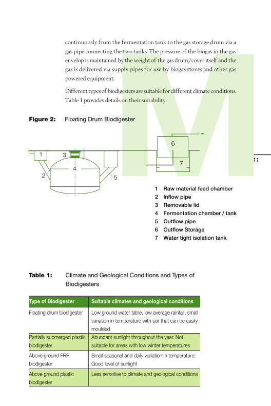
11Mcontinuously from the fermentation tank to the gas storage drum via a
gas pipe connecting the two tanks. The pressure of the biogas in the gas
envelop is maintained by the weight of the gas drum/cover itself and the
gas is delivered via supply pipes for use by biogas stoves and other gas
powered equipment.
Different types of biodigesters are suitable for different climate conditions.
Table 1 provides details on their suitability.
1 Raw material feed chamber
2 Inflow pipe
3 Removable lid
4 Fermentation chamber / tank
5 Outflow pipe
6 Outflow Storage
7 Water tight isolation tank
Figure 2: Floating Drum Biodigester
1
2
3
5
7
6
4
Table 1: Climate and Geological Conditions and Types of
Biodigesters
Suitable climates and geological conditions
Low ground water table, low average rainfall, small
variation in temperature with soil that can be easily
moulded
Abundant sunlight throughout the year. Not
suitable for areas with low winter temperatures
Small seasonal and daily variation in temperature.
Good level of sunlight
Less sensitive to climate and geological conditions
Type of Biodigester
Floating drum biodigester
Partially submerged plastic
biodigester
Above ground FRP
biodigester
Above ground plastic
biodigester

Glo
bal E
nvi
ron
men
tal In
stit
ute
Above Ground Plastic (polyethylene)Biogas Digester
Characteristics: Made with hard plastics (polyethylene or PVC), the
biodigester is placed directly on the ground. It can passively absorb heat
from the sun, thereby increasing the temperature of the digestion tank. In
winter, an insulation layer can be added to prevent temperature loss. The
biogas production and gas storage systems can be pre-fabricated in factories,
and can be installed and transported easily. A highly efficient, stable and
reliable gas production system reduces problems with water or gas leakage.
This type of biodigesters is economic (affordable) and has a long
operational lifespan. In addition it can be adapted easily and has high
degree of operationally flexibility. An electric mixing unit can be added
to increase the rate of gas production.
Suitable areas: all climate and
geological conditions
Table 2 provides details in
terms of the costs of various
PVC biogas fermentation
tanks and their different
characteristics.
Figure 3 shows a PVC fermen-
tation tank and Figure 4 shows
a gas storage bag.
Mai
n ty
pes
of h
ouse
hold
bio
gas
dige
ster
Figure 3: PVC Above Ground Biogas
Digestion Tank
Figure 4: Gas Storage Bag

13
No. Part name Descriptions Nnits Quantity
1 Digestion tank Cylinder Each 1
2 Gas storage bag Each 1
3 Two rings biogas stove desk top Each 1
4 Integrated purifier Each 1
5 Gas pipe Ø8mm metre 10
6 Clips Each 5
7 Tube clamps Each 1
8 Ball valves Ø40mm Each 3
9 Sealing Tape Rolls 1
10 Plastic Connectors Each 5
11 Funnels Ø35mm Each 1
12 Copper 3-way connectors Each 5
13 Plastic pipes Ø40mm metre Depends on the
distance between
the gas tank and
the stove
14 Plastic connectors Ø40mm Each 2
Table 2: Characteristics and Costs of PVC Above Ground
Digestion Tanks
Note: Operational lifespan is assumed to be 10 – 15 years. Price varies according
to regions.
Installation: Table 3 shows a list of parts. Figure 5 is the system installation
diagram
Table 3: Above Ground Plastic Single Family Biogas Digester
System
2 1 25 20 3 1.3 1600
3 1.5 25 30 5 1.7 2000
4 2 25 40 5-8 2 3500
5 3 25 40 10 2.3 4000
6 4.5 30 50 10-12 2.6 5500
7 5 30 60 15 3 6000
8 6 35 60 15-18 3.2 6500
Volume of
digestion
tank (m3)
Daily gas
production
(m3)
Feed cycle
(days)
Solid
effluents
produced per
day (kg)
Size of
family
supported
Area
required
(m3)
Costs
(RMB)

Glo
bal E
nvi
ron
men
tal In
stit
ute
Techn
HouseholdBiogas
To avoid insufficient gas pressure, the digestion tank should not be sited
more than 30m from the kitchen where the biogas will be used.
1. Effluent outflow
2. Gas extraction point
3. Rubber (soft) gas pipe connecting
fermentation tank and gas tank
4. Gas storage bag
5. Gas flowmeter (not required)
6. Gas pressure gauge
7. Light switch
8. Biogas stove / cooker
9. Biogas light
10. Temperature sensor
11. Effluent outflow tap
12. Observation window
13. Feed inflow
14. Feed inflow tap
15. Feed inflow funnel
Figure 5: Above Ground Plastic Biodigester Installation Diagram
Safety warning:
Use of fire or the lighting of fire is strictly forbidden near
to the digestion tank or the (external) gas pipes
Entry into the digestion tank is strictly forbidden
without proper inspection and examination
Lighting of fires is prohibited near the gas outlet and
the effluent outflow at the digestion tank
Mai
n ty
pes
of h
ouse
hold
bio
gas
dige
ster

15
ology
Floating Drum BiodigesterCharacteristics: Gas pressure in the digestion tank is low and it has less
stringent requirement for prevention of water seepage from/into the
fermentation tank. However, the cost of construction of the biodigester
is high, requiring larger area and longer construction time and it is more
difficult to construct. The biogas product system can be affected easily
by the level of groundwater table, annual rainfall and variation in winter
temperature (where the system is installed). In order to increase the
temperature of the fermentation tank, these systems are installed inside
greenhouses or in covered animal sheds and slurry /slag removal pumps
are used for stirring and slurry removal
Suitable areas: Suitable for areas where groundwater table is low, with
low average annual rainfall, with soil that can be easily worked (moulded)
and small variation in winter temperature for example: Shanxi, Gansu and
Ningxia provinces in China.
The characteristics and cost of floating drum biodigester fermentation is
indicated in Table 4
Installation: Table 3 shows a list of parts. Figure 5 is the system installation
diagram
Fermentation tank design:1. Cylindrical tank, domed roof, sloping base, roof (top) window,
movable lid, tank base slopes downward from the raw material inlet
down to effluent outlet, cover for each inlet / outlet / openings,
floating gas storage drum and associated hydraulic tank
Note: Operation lifespan 5 – 8 years. Price varies according to regions
Table 4: Characteristics and Costs of Floating Drum
Biodigester
8 0.5 15 5 20 2 2,500
12 1.5 30 10 30 3 3,000
50 10 30 20 35 3-4 20,000
Daily gas
production
( m3)
Feed cycle
(days)
Area
required
( m2)
Solid
effluents
produced per
day (kg)
Size of
family
supported
Volume of
digestion
tank ( m3)
Costs
(RMB)

Glo
bal E
nvi
ron
men
tal In
stit
ute
Positioning the pit: Setting up the outline of the pit is the first hurdle in
ensuring the quality of the biodigester. It is an important step in planning
the positioning of the fermentation tank, the effluent outlet, the raw
material inlet, the toilet, the pig sty and the glasshouse. Figure 6 shows an
overall template that can be used as a reference to set up the outline of the
overall system.
Pit excavation: First, it is important to define the vertical position of the
baseline at which the height-zero is measured. The depth of the pit should
be checked against the construction blueprint (design), which means the
roof of the biodigester and the effluent outlet should be kept at the same
height. Raw material inlet should be 2 cm higher than ground level. If the
pit is too deep, and the fermentation tank is lower than the ground level,
operation of the biodigester will be affected. If the pit is too shallow, the
biodigester will rise above ground level, and may create difficulties in pig
rearing or in the application of fertiliser in the greenhouse. Table 7 shows
the specification for the construction of floating drum biodigesters
between 8-10m3; Figure 7 gives a template for pit excavation.
Table 5: Floating Drum Biodigester Construction Material
Requirements and Quality
Note: No 16 rebar should be used, the unit used is tonnes.
Mai
n ty
pes
of h
ouse
hold
bio
gas
dige
ster
2. The arc/diameter ration of F 1 /D=1/5 , for which the tank water
height (H) is set at H = 1.0 M
3. The volume of the gas storage drum should be based on 50% of the
daily gas production.
Required construction material is listed in table 5
Material 8 m3 12 m3 50 m3
Cement (tonnes) 1.7 2.1 6.69
(Yellow) sand (tonnes) 4.7 6.7 20.4
Gravel (tonnes) 4 5.7 22.5
Clay bricks (block) 1114 1514 6060
Rebar 0.03 0.08 0.839
Biogas stove two rings
Biogas lights No specific requirements
Desulfuriser No specific requirements
Man-hours 55man-days 135 man-days

17
M1. Toilet
2. Raw material inlet
3. Digestion tank
Figure 6: Template for Setting the Outline of the Overall System
5
1 2 2
7
3
4
6
4. Effluent outlet
5. Glasshouse
6. Median line of pig sty
7. Pig sty
Figure 7: Workers Digging the Pit for the Fermentation Tank
Table 6: 8-10m3 Floating Drum Biodigester Construction
Specs
8 2.70 1.00 0.54 1.96 2.18 1.00
10 3.00 1.00 0.60 2.18 2.28 1.10
Volume
(m3)
internal
diameter
(m)
Height
of pit wall
(m)
Height
of dome lid
(m)
Radius of
dome (m)
Gas drum
isolation tank
(Hydraulic room)
Depth
(m)
Diameter
(m)

Glo
bal E
nvi
ron
men
tal In
stit
ute
Mai
n ty
pes
of h
ouse
hold
bio
gas
dige
ster
Modular biodigester construction:Modular biodigester construction refers to the use of cement in the
construction of the pit bottom, the pit walls and the hydraulic tank bottom.
Brick is used for the construction of the dome of the digestion tank and
the top portion of the hydraulic tank. During the mixing of the concrete,
the following specification must be strictly followed: water-cement ratio
≤ 0.65 , soil in sand ≤ 3%, mica content ≤ 0.5%, gravel diameter ≤ 3 cm, and
amount of soil ≤ 2%. When using concrete it should be poured
continuously, if a pause is needed between each pour, it should not
exceed 1 hour. The concrete should be compacted under constant
vibration while pouring to prevent air bubbles. The installation procedure
is as follows:

19
Figure 8: Discharge Channel Constructed from Bricks (in mm)
1. Discharge Channel: Shown in Figure 8, the discharge channel is
fabricated from clay bricks and sand-lime mortar in layers, with a
cement-to-sand mixture ratio set at 1: 2.5. In order to ease construc
tion the discharge channels should be 50cm wide and 70cm high,
with a raised arch at the top. The top of the opening should not be
less than 35cm from the top dome of the digester, in order to prevent
gas from escaping under the surface of the liquid (inside).
2. The Base and Walls: The base and walls are both subject to pressure
from pouring. The digester walls and base can be constructed using a
concrete mould made of steel sheeting, wood, or bricks. This
constitutes the internal layer of the mould, with the dirt wall of the
pit as the outer section. Due to its high costs steel sheet moulds are
rarely used, therefore wood and brick moulds are preferred. Where
several digesters are to be constructed in the village, it is more
common to use wooden moulds. Where only one is to be built, a
brick lining should be adequate.
The usual course for constructing a brick mould is as follows: first,
soak the bricks in water to prevent problems with removing the
mould. Then, lay the bricks horizontally in a line around the edge of
the mould, with each layer added on type slightly offset, taking care
to keep the bricks free of mud and dust. Once each layer of bricks has
been completely laid, pour a layer of concrete (between the bricks
and pit wall), and once correctly braced and compacted, continue
15# Concrete
makegravel andsand level
soil
soilmortar
15mmthick brick
15# Concretemakegravel
andsand level
soil

Glo
bal E
nvi
ron
men
tal In
stit
ute
BiogasHousehold
Technology
Mai
n ty
pes
of h
ouse
hold
bio
gas
dige
ster
laying the next brick layer. The concrete should be made up on the
following ratio according to weight: cement:sand:gravel 1:3:3.
Walls should be poured to a height of 1m and a thickness of 5cm.
3. Digester Dome Shaped Cover. Up until now, the covers of
separated floating cover type digesters have been constructed from
bricks and a vertically positioned intake pipe. The intake pipe should
be posi tioned properly before construction of the brick dome
commences, the usual ceramic pipe dimensions are 200mm
diameter x approx 600mm long. This pipe is secured to a
wooden peg, such that it stands vertically positioned (top-to-bottom),
and is fastened to the digester wall. A suitable depth for the pipe to
extend into the digester is 250 - 300mm from the dome.
The brick dome cover can use metal fittings or rope to hold the
bricks in place. Bricks should be built out from the position of the
intake pipe, although cement will be needed close
to the pipe itself. Bricks used in construction of the dome cover
should be good quality. They should first be pre-soaked in water;
care should be taken to ensure the exterior is wet whilst the inside
remains dry. They should be laid using a 1:2 cement: sand mortar
ratio. Care should be taken to ensure all gaps are filled,
and the bricks are flush against each other, using smaller rock
fragments or gravel as wedges to complete each layer. Attention
should be paid simultaneously to the laying of bricks and
the need to maintain shape of the dome.
When 3 to 5 layers have been achieved a 1:3 cement: sand grout
should be applied carefully. When applying grout to the 1st ring of
bricks, the thickness should be between 30-50mm, to substitute for
arch supports. As the laying and grouting is occurring, some of the
dirt can also be returned, and spread evenly. Before replacing the soil,
a few layers of brick should be added to the intake pipe, in order to
prevent soil from entering the digester while it is being replaced.
240mm is an appropriate diameter for the intake pipe, while the
length should be sized according to need. At first, the replaced dirt
should only cover 60% of the dome surface, in order to prevent
collapse. After about 10 days soil can be replaced so that it totally
covers the recessed dome. A construction blueprint for a digester
dome cover is given in Figure 9.

21
At the same time as the dome is constructed, the top half of the water
pressure chamber should be constructed by way of laying quarter-
piece bricks vertically (standing up), using 1:3 ratio cement (one part
cement to 3 parts sand/lime).
When it comes time to close up the top of the dome, a 9-19mm
copper gas extraction (outlet) pipe should be installed as suggested
per Figure 10.
Figure 9: Dome Cover under Construction
Figure 10: Gas Extraction Pipe
Gas Extraction Pipe

Glo
bal E
nvi
ron
men
tal In
stit
ute
MMain types of household biogas
dige
ster
4. Digester Base: First, a layer of gravel should be put down and covered
with a 1:4 cement: sand slurry. This should then be followed with a
layer of concrete made from cement, sand, and gravel in a 1:3:3 ratio.
This concrete layer should be at least 8 – 12 cm thick. An example is
given in Figure 11.
5. Sealing the interior of the digester tank. Walls constructed from
concrete and bricks only provide the digester with structural support,
and do not prevent gas leakage. Therefore, it is necessary to treat the
wall of the digester with a sealant to prevent gas and water leakage.
There are two main treatment types: the 7 layer method, and the 3
layer method. The 7-layer method should be used for the gas storage
chamber and the area of the digester interior near to the feedstock
intake pipe. The 3-layer method should be used for the base, walls,
water pressure chamber, and discharge channel.
7-Layer MethodLayer 1: #45 cement and sand-lime are used to from
a mortar with the ratio of 0.3:1
Layer 2: a mixture with a 1:2.5 ratio of cement to
sand is applied to a thickness of 0.8 to 1 cm
Layer 3: a 0.1 cm layer of soda ash is applied
Layer 4: a mortar of cement and sand in the ratio of
1:2 with a thick ness of 0.4 cm
Layer 5: 0.1cm of soda ash
Layer 6: 1:1 mixture of fine sand & ash to a thickness
of 0.3-.04cm
Layer 7: 3 applications of soda ash slurry.
3-Layer MethodIn the case of the 3 layer process, the processes described
above for the 2nd, 6th and 7th layers should be applied.
6. Curing. All components of the digester made
from concrete or cement will need to undergo
curing, and for this to naturally occur the ambient
temperature should be above 5 degrees Celsius.
Surfaces exposed to the elements should be covered
with straw matting and the matting should be slightly
moistened. The matting should be kept up for a
period of 7 to 10 days. In spring and in autumn it is

23
also important guard against frost. In order to achieve the aim of
success fully curing the concrete and brickwork, once the inside has
been treated with sealant, then the intake, discharge outlet and top of
the digester should be covered or wrapped with film. Once the
required period has elapsed, the digester should be examined and (if
possible) pressure tested. Upon passing inspection, feedstock can be
put into the digester and it can begin to be used. If it rains within the
first twenty-four hours of operation, then the digest should be
immedi ately filled with water to approximately half capacity, in
order to prevent water seeping under the base and floating the
digester out of its hole & footings.
Figure 11 Constructing the Base

Glo
bal E
nvi
ron
men
tal In
stit
ute
BiogasHous
Techn
Partially Submerged Plastic DigesterCharacteristics: The characteristics are generally the same as the Above
Ground Plastic Digester. To enhance stability, a shallow hole is required,
and to prevent leaks from being created sharp tools should not be used
for making the hole. Figure 12 below shows the fully constructed digester,
with the extensions on the left and right side forming the outlet and inlet,
with gas being extracted from the top of the dome.
Suitable Locations: Areas with abundant sunlight all year round are best.
It is not appropriate for regions with low winter temperatures. A com-
parison of installation specifications and cost for different scenarios is given
in Table 7 below.Mai
n ty
pes
of h
ouse
hold
bio
gas
dige
ster
Table 7: Comparison of Different Digester Sizes
Figure 12: Partially Submerged Plastic
Digester (basic form)
2 1 15 20 3 1.7� 1.2 1210
3 1.5 15 30 3-5 1.7� 1.8 1235
4 2 20 35 3-5 2.2� 1.6 1270
5 2 20 40 5 1.8� 2.4 1445
6 2.5 25 45 5-8 1.8� 3.5 1550
7 3 25 50 8 1.8 � 4 1665
Digester
Capacity
(m3)
Daily Gas
Production
(m3)
Cycle
Period
(Days)
Quantity of
Sediment
Produced Daily
(kg)
Persons in
User
Household
Area
Occupied
(sq m)
Price
(RMB)

25ehold
ology
Digester Installation:1. The position selected for installation is usually one with abundant
sunshine. In northern areas (in northern hemisphere countries), the
digester should be constructed in a greenhouse.
2. For the inlet and outlet pipes hard plastic (e.g. PVC) or metal piping
should be attached to the concrete. Where the piping is in contact
with the concrete, use putty or waterproofing tape to create a seal.
The inlet and outlet should be attached to the digester only after the
digester has been stabilized, to prevent the pipes from pulling out of
the cement.
3. Once the digester has been completed, the inlets/outlets should be
covered with film or a concrete plug. However film creates a better
seal.
4. The gas extraction nib should be attached at the correct depth, with
the threaded section in contact with the digester shell, using putty or
sealing tape to seal around the joint. The other end should be attached
to the extraction pipe.
5. The extraction pipe should be at a slight angle to prevent water from
building up inside the pipe, allowing condensation to flow back into
the digester.
6. Lights, stoves, range hoods, valves and pipes should be kept far apart
from open flames and flammables, in order to prevent explosions.
7. The inlet should be fitted with a (coarse) sieve to prevent unwanted
material entering the digester.
8. If using high pressure lamps or stovetops, bricks should be placed on
top of the removable cap (see diagram below), ensuring that the
bricks are kept from touching the wall of the digester. The quantity
of brick depends on the distance of the lamps from the digester. It is
preferable to use low pressure lamps.
9. Installation should be as per the diagram given in Figure 13.
Points to consider:
1) Installation is convenient, only requiring a shallow hole of 400 to
500mm deep.
2) For households or users with sufficient finances, the digester can be

Glo
bal E
nvi
ron
men
tal In
stit
ute M
placed in a greenhouse. Otherwise covering the outside of the digester
with rice straw or netting will extend the life of the digester.
3) Wooden stakes can be used to support the intake pipe/inlet.
4) Upon successful installation of the new digester, once it has started to
produce gas add water to the water bag.
Figure 13: Installation diagram.
Fiberglass Reinforced Plastic (FRP) PartiallySubmerged Digester
Characteristics: The overall characteristics are similar to the Plastic Above
Ground Biogas Digester. For stability, a shallow hole should be dug, and
the digester installed within. In order to take advantage of the solar energy
to heat the slurry the top of the Biogas digester is made of a panel of evacu-
ated glass. When gas is produced, the slurry is forced by the pressure of
the biogas to move into the hydraulic (water pressure) chamber, where it
is heated by the sun. The digester is made from imported resin, which is
1. Inlet
2. ‘Fill to’ line
3. Gas Extraction Point
4. Discharge Outlet
5. Wooden stakes
6. DN40 Stopper/Plug
7. Water Bag
8. Flexible Cap (membrane).
Mai
n ty
pes
of h
ouse
hold
bio
gas
dige
ster

27
Table 8: Comparison of Different FRP Digester Sizes
light and durable, easy to assemble/disassemble, seals well, prevents
spoilage, and is reasonably priced. The digester produces gas all year round,
with liquid escaping through a valve, and sediment extracted using a hand
pump as required. There are several safety features included in the design
such as adjustable pressure, back-fire protection, and sediment separation.
As per Figure 14, the digester items at the top of the digester are the inlet,
gas extraction pipe and gas release valve/opening.
Suitable Locations: The best locations are where there are not strong
seasonal nor strong diurnal temperature differences, and where there is
sufficient sunlight.
A comparison of installation specifications and cost for different scenarios
is given in Table 8 below.
Note: Average Useful Life is 3 years, prices differ between regions.
2 2 20 20 5-8 �1.3 � 1.5 2280
3 3 20 30 5 �1.5 � 1.7 2480
4 4 20 40 5-8 �1.5 � 2.3 2880
Digester
Capacity
(cubic m)
Daily Gas
Production
(cubic m)
Cycle
Period
(Days)
Quantity of
Sediment
Produced Daily
(kg)
Persons
in User
Household
Area
Occupied
(sq m)
Price
(RMB)
Safety warning:
Using open flames or playing with fire near to the
digester or extraction pipes is strictly forbidden
Digesters that have not passed inspection should
not be used

Glo
bal E
nvi
ron
men
tal In
stit
ute
BiogasHou
Technology
Installation: As per Figure 15 below.
1. Site Selection: It is preferable that the digester is within thirty meters
of the kitchen or point of use, to ensure that gas pressure is sufficient.
The family pigsty, kitchen and digester should be positioned as close
as possible to increase the efficiency of mucking out the sty and
shifting manure into the digester.
2. Digging the Hole: To easy positioning the digester in the ground the
diameter of the whole should be constructed slightly larger than the
diameter of the digester. The lower section of the hole should be dug
to match the shape of the digester, digging out small sections for the
intake pipe and hydraulic/pressure chamber.
3. Installation: Prior to installing the digester, the shell should be
carefully dusted and inspected for faults, and repaired if found. The
two half-sections of FRP should be thoroughly cleaned out, and rough
sections should be sanded down with sand paper. Then the two
halves of the digester should be placed together such that the dome
sections face opposite directions and the flange or tabs at the base of
each section are flush. The epoxy or bonding solution provided
should be thoroughly mixed together, and then spread evenly over
the gap or groove formed between the two adjoined sections of the
digester, then fasten the M10 sized bolts or screws. Again, a second
batch of epoxy or sealant should be mixed together and spread evenly
over the gap or groove formed between the two adjoined sections of
the digester. Prior to attaching the intake and pressure chamber to the
Figure 14: Household FRP Partially Submerged Digester
Mai
n ty
pes
of h
ouse
hold
bio
gas
dige
ster

29
sehold
main digester body, a quick test should be done to ensure that screw
holes align and the remaining epoxy/sealant should be spread evenly
over the parts to be joined. Before placing the digester in the hole, first
spread a 30-50mm layer of fine grouting sand, with a thicker layer at
the base of the digester arc. Once the digester has been lowered into
the whole, using wooden tomato stakes or something similar, slightly
raise the digester again and gently slide in excess soil around the
digester. Finally, use adhesive to attach the flexible cap to the digester,
screw down with buckle resistant bolts, and then add water.
4. Backfilling: Once the digester is installed as above, fine aggregate or sand
should be used to backfill any gaps between the edge of the hole and
the digester. Alternate between adding soil and adding a small amount
of water (to aid in compacting the soil), then use a wooden pole or
similar rod with a flat base to tamp down the soil around the digester.
In areas with a high water table, water should be added to fill
approximately half of the digester. When tamping down the soil around
the digester, care should be taken not to damage or pierce the digester itself.
Safety warning:
Using open flames or playing with fire near to the digester
or extraction pipes is strictly forbidden
Digesters that have not passed inspection should not
be used
It is strictly forbidden to light the extraction pipe or
discharge pipe.
1 Deep Sand Pit2 Connecting Pipe3 Inlet/Intake4 Evacuated Panel5 Outlet for
discharging liquid(flexible cap)
6 Screws/Bolts7 Overflow Outlet8 Safety Release
Valve
Figure 15: FRP Digester Installation
Diagram
141 2 3 4 5 6 7
89
10 12
1113
9 Desulphuriser(Scrubber)
10 Gauge11 Pressure Gauge12 Stove
(not to scale)13 Light Switch/Valve14 Biogas Lamp15 Sealed Container16 Main Moveable/
Flexible Cap

Glo
bal E
nvi
ron
men
tal In
stit
ute
BiogasHouseh
Te
Basic Operation Steps for Household DigestersInvestigating Leaks: A detailed description is given in Section A: Methods
for Finding the Location of Leaks.
Preparation of Raw Materials:
Starting Culture or Fermenting Agent: The culture used is generally a
slurry obtained from an existing digester mixed with human or animal
manure in a roughly a 2:3 ratio. It should be left to anaerobically digest for
approximately one week covered by a plastic film. If slurry from a
previous digester is not available, sludge from sewer traps can be mixed
with manure and left out for a week in a similar manner. In the event this
substitute can not be found, manure can be mixed with water and left
out to begin anaerobically digestion over a longer period of ten days.
Pre-treatment: Once the culture has been prepared, mix the manure,
culture and water together in a ratio of 1:4:19.
Beginning the fermentation process: New or thoroughly cleaned out di-
gesters need to undergo a short period of preparatory maintenance to de-
termine that there is no vapour or water seepage. Once this has been de-
termined virgin slurry can be added to the digester.
1. Preparation: Pre-treatment of the culture (inoculant or starting agent)
should be done according to requirements. The culture should form
approximately 10 - 30% of the starter mixture and the density of the
slurry would be approximately 6 - 11%.
2. Inserting Virgin Slurry: Combine the starter and culture together
and place into the digester. The density of such as slurry should not
be excessively high, and generally speaking the slurry density has
been kept at around 4%-6%. If manure is the main ingredient, then
density levels should be lower.
Use & Management ofHousehold Digesters
Use
& M
anag
emen
t of H
ouse
hold
Dig
este
rs

31oldchnology
3. Mixing: The mixture should be thoroughly stirred once placed in the
digester.
4. Adding Water & Sealing the Digester: The slurry mixture in the
digester should be 85% of the total capacity. The remaining 15% is to
store the gas produced.
5. Testing of Gas Produced: Once the reading on the gas pressure
column has reached 40cm, gas should be released and test ignited.
Once this has been successfully completed one or two times it can be
used as a fuel. It is very important that test ignitions should be
completed on a suitable burner or stove, and not at the gas extraction
point or directly on the gas extraction pipe to prevent backfire in the
pipe and subsequent explosion of the digester.
6. Finalisation of Commissioning: Once production of gas from the
digester is stable, and the gas has been used [successfully], the
biodigester should be in equilibrium. This means that the quantity of
the micro-organisms, acid levels and methane producing bacteria are
in equilibrium, and the pH level are in order ( the pH should be
above 6 – if not plant derived cinder ash, ammonia or clear limewater
can be carefully added until the pH level reaches 7). Upon reaching
end of this commissioning stage, the digester can enter normal
service.
Adding Material: The basic guiding principle is that the amount removed
is the amount replaced. The waste (spent) slurry or solids should be first
removed before adding new material, and as material is removed care
should be taken to ensure that the material in the digester does not drop
below the top edge or the outlet/inlet, because gas will escape in such a
case. Once material has been removed, new material should be added as
quickly as possible. If there is insufficient slurry or manure to reach to
original water level inside the digester, add water until this level is reached,
to ensure that the gas produced will have sufficient pressure.
Mixing: Once starter culture and manure inputs have been placed in the
digester it is important to thoroughly mix them to ensure that there is
good contact thus speeding up the production of gas. For separation float
type digesters a sediment extraction device should be used. Other
digesters should use included mixing equipment.
Major Clean out: In order to satisfy both the metabolic needs of the

Glo
bal E
nvi
ron
men
tal In
stit
ute
BiogasHousehold
Technology
bacteria and the needs of nearby fields (for fertilizer), major clean outs
are usually performed in the spring or autumn. Twenty to thirty days
beforehand, normal addition of material should cease, in order to prevent
waste of the active culture. Once the major cleanout has been completed,
new material should be added immediately to ensure the digester can
quickly return to production and therefore use. The digester should be
thoroughly cleaned including the removal of all sullage and liquid. 10-
30% of the live liquid should be set aside to use as the starter culture in the
next batch, in order that the digester can quickly return to service, and
begin gas production.
Management of Household DigestersMaintaining Temperature During Winter: It is important to manage the
temperature for naturally heated digesters in the winter when the
temperature is relatively low, many different materials should be used as
feedstock for household digesters. Temperature is a key factor
influencing the speed of gas production, and within a certain range, the
higher the temperature, the higher the speed of gas production. As such,
it is important to take measures to increase temperature in the digester. If
the aim is to increase winter gas production, a simple saying goes: ‘eat your
fill, (and) rug up well.’ As winter approaches, the following steps should
be completed:
1. Increase the density of the slurry in the digester, increasing to about 10%
2. Due to the large diurnal temperature difference at the start of winter,
special attention must be paid to night time digester temperatures.
As soon as possible, the digester should be covered; as the temperature
falls, and once the sun has set, the digester should be covered with
straw matting or other insulating material to keep the heat in.
3. To help raise gas production it is important to add new slurry/
feedstock and remove spent slurry diligently to provide the bacteria
with necessary nutrients.
4. Diligently Circulate or Mix Digester Contents: Floatation type
digesters should be mixed every three to four days. This can be
achieved by cycling ten to fifteen buckets (in volume) through the
pressure chamber to the entry pipe; such mixing can be achieved in
other digesters using the equipment supplied.
Use
& M
anag
emen
t of H
ouse
hold
Dig
este
rs

33
U
Daily Management: To prevent damage to the digester the pressure gauge
should be checked often, and when vigorous gas production causes
overpressure, gas should be used as quickly as possible, or a suitable stove
ignited. If using a directly coupled pressure gauge attached to the extrac-
tion pipe, a safety valve should also be employed to prevent digester
explosion. In the event of an explosion, nearby open flames must be
extinguished, to prevent further fire-related accidents.
In regards to separated float digesters, if feedstock has recently been added
to the digester, take care not to rashly remove spent slurry or enter the
digester without first taking adequate safety precautions. The safety
precautions include: first, open the cap and flush the inlet/outlet and top
with fresh air (or use a ventilation fan to refresh the airspace). Second,
observe the digester for 15 – 20 minutes, and when it is cleared out, the
digester can be entered; if abnormalities exist, entry should be strictly
avoided. Third, persons entering the digester should be secured by a safety
harness and observed by suitably qualified personnel. If the worker
inside the digester signals discomfort, the observer should pull them out
immediately, after which the affected worker should be taken to a
ventilated area to recover. Once the floating cap or cover has been exposed,
smoking is then prohibited, and there should be no open flames within
the vicinity of the digester. Workers inside the digester should use
electric torches or mirrors to light the digester; open flames are strictly
prohibited. Open flames should never be used to burn off surplus gas
directly in the digester, as that would cause the digester to explode.
Suggestions to Improve Gas Production: Ensure the temperature is kept
relatively high; when conducting the biannual large scale cleanout, retain
some fermented liquid to use as the starter culture for new batches; stir
the mixture often.
Methods for Finding Leaks in the Digester: Generally speaking, first check
the exterior, secondly check the interior, gradually checking off likely
places, and treat according to the problem, on the basis of the following
steps:
1. Checking the External Surfaces for Leaks
Coil up accessible flexible pipes and tie with a string. Submerse this
roll in water and pass air or gas through it (or blow into it). At the
same time, check the pipe, valves and stoppers for air bubbles because
these indicate holes or leaks. When the hosing and joints are in use, a

Glo
bal E
nvi
ron
men
tal In
stit
ute
BiogasHous
Te
brush can be used to apply soapy water to valves, elbow joints,
connectors, T-joins, step-down/step-up fittings and the pipe, checking
for bubble formation. In addition, it is important to check around the
gas extraction point, the joint between digester cap and the top of the
digester, and around the floating cap. These are areas where leaks
easily develop and should be inspected regularly.
2. Process for Inspecting Internal Surfaces
In the case of separation float digesters, first check for any external
leaks as described above, when it has been confirmed that the leak is
internal the contents of the digester must be removed and the
digester cleaned out. After allowing time for all of the gas to dissipate,
the digester walls, cap, base and outlets/inlets should be visually
inspected for holes and cracks. The gas extraction pipe should be
fixed in place where it cannot move. It is especially easy for cracks to
form around the inlet/outlets; therefore they should be carefully
examined. The walls of the digester should be checked for signs of
seeping water; in digesters where this is not an obvious layer of dry
cement, ash can be applied, whereby damp spots and lines can be
readily identified as likely leaks. Leaks in other digester types are
generally found by external examination. This can be achieved on
operation digesters by spreading soapy water over the surface of the
digester and introducing air to the chamber, checking for bubbles
that indicate leaks.
Safety Points: STRICTLY No fires permitted near the digester or extraction pipes. STRICTLY No unqualified personnel to are to enter digesters. STRICTLY No fires should be lit at the spent slurry discharge outlet
nor directly on the gas extraction pipe.
Safe Fermentation:
1. In order to maintain the helpful gas producing bacteria, care should
be taken to insure that they are not poisoned by pesticides such as:
organic bactericides and antibiotics, including recently sprayed crop
waste or leaves, and disinfected animal waste, and naturally occurring
pesticides such as garlic and peach leaves etc, as well as heavy metal
compounds & salts (such as wastewater from electroplating
processes). These compounds should NEVER be allowed to enter the
Use
& M
anag
emen
t of H
ouse
hold
Dig
este
rs
35ehold
chnology
digester. If they do enter the digester, gas production will stop. In the
event that this occurs, the entire contents of the digester must be
removed and refreshed with completely new materials.
2. It is forbidden to empty oil, bone meal or phosphorous material into
the digester, or any products containing phosphorous.
3. Poisoning due to alkalinity must be avoided. The main cause of this is
the over addition of material with high alkalinity, for example lime.
Where the pH exceeds 8.5, this generally results in poisoning of the
bacteria and is sometimes accompanied by an increase in ammonium
nitrate. The effects of alkaline induced poisoning are similar to acid
induced.
4. Preventing Ammonia Related Poisoning. The main causes are the
addition of personal or animal waste with a high nitrogen content,
excessive density of the slurry mix or the lack of bacteria/starter
culture. It has similar effects to the alkaline situation decided above.
Safety Management:
1. Caps should be placed on the discharge pipe (or channel) to prevent
people and/or animals from entering the digester and accidentally
dying.
2. Regularly inspect the gas transmission system, to prevent fires arising
from leaks.
3. Children should be educated to understand that they should not play
with fire near the gas extraction pipes, distribution system, nor
digester, and [the children should be taught] not to play with valves
and switches.
4. Pressure on the pressure gauge should be regularly checked and
changes observed. When gas production is vigorous, and pressure
exceeds desired levels, excess gas should be quickly used up or burned
off on a suitable stove, in order to prevent swelling of the digester and
subsequent explosion. Water in the pressure gauge should be refilled.
In the event that the top or cap is blown off the digester, nearby open
flames should be immediately extinguished, to prevent further
explosions.
5. When adding materials and slurry to the digester, if there is a lot of
material, new material should be added slowly. If removing a

Glo
bal E
nvi
ron
men
tal In
stit
ute
BiogTechnology
Usubstantial amount of spent material, and the pressure gauge
subsequently drops to zero, open the material inlet, in order to
prevent damage that would result from excessively low pressures.
6. Adequate steps must be taken to prevent wintertime and frost
damage.
Safe Use of Gas:
1. The first step towards the safe use of gas is selecting components that
have passed national certification standards.
2. Gas lamps, stoves, and transmission pipes should be kept apart from
firewood and other flammables, in order to prevent fire. In the event
of a fire, it is important not to panic, but rather to immediately turn
off all valves and to disconnect the distribution pipes from the
extraction point on the digester. Once the fuel source has been
disconnected, immediate action should be taken to put out the fire.
3. When determining if a new digester has produced gas, this should
only be done by test ignition on a suitable stove or burner, and
STRICTLY never at the gas extraction point or on the discharge
outlet or other spent material removal point. Following this course of
action will prevent explosion of the digester.
4. When using gas, first light the match or start the ignition source, in
order to prevent excess gas being released and the subsequent
burning of nearby personnel once ignited.
5. If putrid gas is detected in the room or rooms, nearby windows
should be immediately opened and the location ventilated, making
sure not to use open flames, in order to prevent possible explosions.
Safe Removal of Spent Materials and Other Maintenancein Separated Float Digesters:
1. When entering the digester to remove materials or to conduct
maintenance, safety and preventative measures must be taken. The
floating/flexible cap should be open for several hours, scum should
be removed and a portion of the liquid removed. Open the discharge
outlet, inlet and cap, to allow airflow through all three, in order to
evacuate remaining gas. If persons entering the digester begin feeling
dizzy or stuffy, then they should be immediately removed from the
digester and allowed to rest. When entering digesters that have been
Use
& M
anag
emen
t of H
ouse
hold
Dig
este
rs

37
gasHousehold
out of use for several years, special care should be taken as gas may be
trapped under a crust of dung and sediment on the floor. If persons
carelessly enter digesters without regard for safety precautions and
without taking suitable safety measures, accidents are very likely. As
much as is possible, mechanisms provided to remove material from
the digester should be used, thus negating the need for people to
enter the digester, increasing safety and convenience.
2. When opening the digester cover, it is important that no nearby
persons are smoking, and that no other sources of ignition are present.
When inside the digester, only battery flashlights or electric lights
should be used for illumination; lanterns and candles should not be
used, and workers may not smoke in the digester.
Remedies for Common Problems or Accidents:
1. Fainting: In the event of workers fainting (passing out) inside the
digester, and the person cannot be quickly retrieved, then methods
must be used to fan fresh air into the digester to ventilate it. Under
no circumstances should other people jump into the digester blindly
without taking this precaution, otherwise further persons may faint
or asphyxiate.
2. Treating Faint Victims: Once retrieved, the person who fainted and/
or suffocated persons should be taken to an area sheltered from wind.
Their clothing and belt should be loosened whilst keeping them
warm. Lightly affected persons will quickly regain consciousness,
whilst severe cases should be taken immediately to the nearest
hospital.
3. Extinguishing Fires: For persons burned by methane burning clothes
should be removed immediately. The person should lie on the
ground and roll about, or jump into water. Surrounding individuals
can assist the victim to use other suitable methods to extinguish the
fire. Bare hands should not be used to swat at the fire, and victims
should not run about in a flurry or panic, as this will increase the
intensity of the fire.
4. Treatment of Burns: After extinguishing all fires, cut away burnt
clothing, and use clean water to gently wash the affected area. Use q
fresh clothing, sheets or bandages to wrap burns and/or complete
body as appropriate, ensuring in cold or cooler seasons that the person

Glo
bal E
nvi
ron
men
tal In
stit
ute
is kept warm. Then the person should be taken to the nearest
hospital’s emergency treatment department.
Below is a chart detailing common problems and suggested courses of
action.
Table9: Chart Showing Troubleshooting Approaches & Remedies
Use
& M
anag
emen
t of H
ouse
hold
Dig
este
rs
Problem Symptom Cause Solution
Remove some of the
contents; Flush out
the distribution pipes.
Gas quality is good,
but production rate
is low
Ratio of inputs is
not correct;
Too much spent
slurry
Choose a ratio or thickness
of between 6 and 10%;
Regularly remove spent
materials and introduce
new feedstock/manure.
New slurry quantity
is accurate, mixture
ratio is correct,
but no gas is produced
Leakage
Search for the leak as
described in the
above section and
repair as appropriate
Gas production
is sufficient,
but is not flammable
Acidity/Alkalinity
incorrect, most likely
too acidic; too much
new material has
been added
Add a small amount
of lime or ammonia
to the mix; Add old manure
from the base of a
previous storage area
Gas production is
good, water level
(on gas meter )
rises sufficiently
but then stops
A hole in the
input pipe
Examine and repair
input pipe
As gas is burning,
pressure gauge
responds erratically,
and flame flickers
Water is lodged
in the transmission
pipe
Check joins in the pipe
for water, disconnect,
and remove.
Pressure on the gauge
appears high, but falls
immediately following
ignition
Too much material
inside the digester
(in the case of float
digesters)
Transmission pipes are
blocked

39
Installation and Use of Gas Lights & StovesTo safely, efficiently and correctly use gas lamps and burners, first it is
necessary to select components that meet or exceed national standards
for burners and lights.
There are many different kinds of stove tops (burners) and lights, and as
such there are differences in installation. The best guide is to follow the
manufacture’s installation instructions.
Glo
bal E
nvi
ron
men
tal In
stit
ute
Househ
Technology
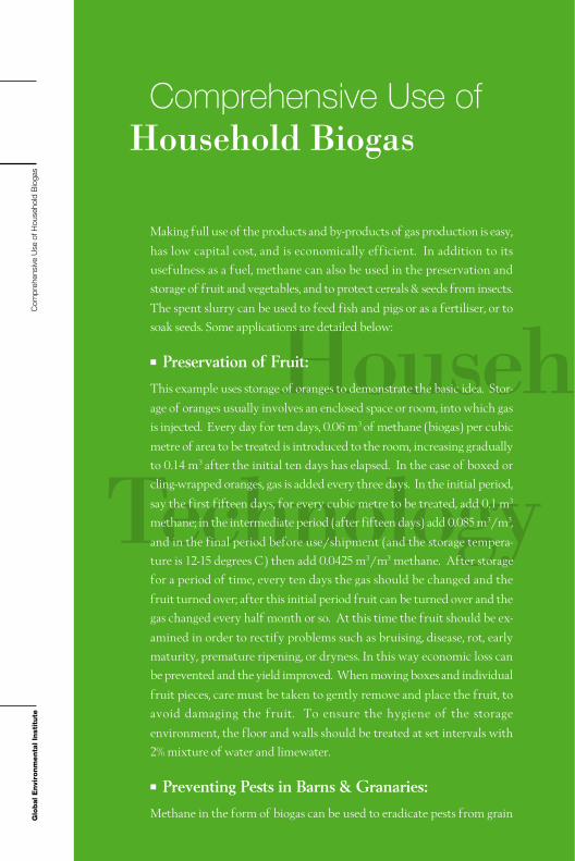
Making full use of the products and by-products of gas production is easy,
has low capital cost, and is economically efficient. In addition to its
usefulness as a fuel, methane can also be used in the preservation and
storage of fruit and vegetables, and to protect cereals & seeds from insects.
The spent slurry can be used to feed fish and pigs or as a fertiliser, or to
soak seeds. Some applications are detailed below:
Preservation of Fruit:This example uses storage of oranges to demonstrate the basic idea. Stor-
age of oranges usually involves an enclosed space or room, into which gas
is injected. Every day for ten days, 0.06 m3 of methane (biogas) per cubic
metre of area to be treated is introduced to the room, increasing gradually
to 0.14 m3 after the initial ten days has elapsed. In the case of boxed or
cling-wrapped oranges, gas is added every three days. In the initial period,
say the first fifteen days, for every cubic metre to be treated, add 0.1 m3
methane; in the intermediate period (after fifteen days) add 0.085 m3/m3,
and in the final period before use/shipment (and the storage tempera-
ture is 12-15 degrees C) then add 0.0425 m3/m3 methane. After storage
for a period of time, every ten days the gas should be changed and the
fruit turned over; after this initial period fruit can be turned over and the
gas changed every half month or so. At this time the fruit should be ex-
amined in order to rectify problems such as bruising, disease, rot, early
maturity, premature ripening, or dryness. In this way economic loss can
be prevented and the yield improved. When moving boxes and individual
fruit pieces, care must be taken to gently remove and place the fruit, to
avoid damaging the fruit. To ensure the hygiene of the storage
environment, the floor and walls should be treated at set intervals with
2% mixture of water and limewater.
Preventing Pests in Barns & Granaries:Methane in the form of biogas can be used to eradicate pests from grain
Comprehensive Use ofHousehold Biogas
Com
preh
ensi
ve U
se o
f Hou
seho
ld B
ioga
s

41
Biogasold C
storage for up to one year. The following includes instructions on how to
achieve this.
On the top section of a silo or granary, attach a 0.1- 0.2 mm layer of
polyethylene film, installing a small pipe in the centre at the peak as an
exhaust or ventilation pipe, which should be attached to an oxygen
detector or to a carbon dioxide monitor. In this way, readings about the
air inside the silo in terms of CO2 or oxygen content can be readily
obtained.
At the base of the storage pile or silo, a radial diffuser fitting should be
placed and attached to a gas distribution pipe. A gas flow meter should be
incorporated into this branch of piping, and in this branch should in turn
be connected to a switch or control valve. Once the diffuser and pipes
have been installed and checked for leaks and blockage, the methane gas
valve can be opened, and gas added to the silo. Under the pressure
provided by methane gas entering the base of the silo, air from within the
silo will be forced out through the exhaust pipe at the top of the silo
through the gas monitor and out into the open. Once a quantity of
methane gas equal to 1.5 times the volume of the silo has been passed
through in this way, and oxygen gas monitor verifies that the oxygen
content has dropped to between 1�5%, or that CO2 has reached 20�
30%, then the ventilation pipe and valve at the base of the silo should be
turned off. Left for three days, this will eradicate mealie beetles, weevils,
and other similar pests, and will generally remain unaffected for up to
one year.
Preventing Pests in Containers:The methane grain protection technique is also suitable for household or
other small sized containers, including porcelain jars, pots, crocks, barrels,
and small cement pits. Generally, the containers are plugged with wooden
stoppers or corks, with small holes that have been drilled to insert gas pipes.
A gas ‘input’ pipe supplying the methane gas is inserted into one hole, and
an exhaust pipe into the other. If there are many such pots, they can be
connected in series i.e. the exhaust of one pot can be connected to the
input of another pot. Small gas diffusers can be made from bamboo,
connected to the pipe on the inside of the stopper, and placed in the
bottom section of the pot. Once the pot or jar is full of grain, the stopper
should be replaced and a small amount of paraffin wax or other sealant

Glo
bal E
nvi
ron
men
tal In
stit
ute
can be used to seal the groove around the stopper and top of the pot. A T-
piece connector should be attached to the external end of the exhaust
pipe, and a pressure gauge and valve added to the other ends, or even gas
lamps and stoves. The first time that the storage vessel is flushed, the
exhaust valve should be opened and connected to a burner, lamp or stove,
and gas passed through the vessels until a flame can sustain the burner/
lamp. The valve on the input and exhaust pipes should then be closed,
and the vessels left sealed for 5 days, which will kill any insects in the grain.
Soaking Seeds:Soaking seeds in spent slurry prior to germination develops overall more
hearty plants. The process of soaking the seeds starts by first, placing
fifteen to twenty kilos of seed in to a cloth/weave type bag with good
water penetration qualities. Soak the bag in the discharge chamber of the
digester, or some other vessel containing spent slurry, for approximately
48�60 hours (in the case of seeds with shells like rice), and for about
12�18 hours in the case of corn and other shell-less seeds. Finally, take
out and wash, air, then following this process of accelerated germination,
and sow the seeds in the ground as required. As a result of soaking in the
slurry, rice germination rates are 5�10% higher than water alone, and
approximately 20% more seeds reach seedling stage (than water soaking).
Rice overall is more vigorous, it has better root growth, thicker stems and
deep green foliage, a stronger response to transplanting and earlier budding.
Yields can also increase by 5�8%. For corn, seeds sprout much earlier and
yields can increase by 10�18% over standard sowing. Wheat germina-
tion rates increase by approximately 3% following slurry soaking,
Figure 16: Jars Connected in Series for Grain
Storage Using Methane.

43Cpromoting strong growth of seedlings, with longer and more roots. In the
same soil and conditions, yield from wheat that has been soaked (in spent
slurry from the digester) will be about 7% higher than that for water alone.
Using Spent Slurry and Sediment as a Fertiliser:After filtering or sieving the slurry to remove large bio-solids, the slurry
can be spread in early morning (around 8am�10am). As much as possible,
apply it to the back of leaves, as this helps the absorption of nutrients. Pay
special attention to only apply an amount that is appropriate for the growth
of the crop. If pesticides are to be mixed In with the slurry, this should
first be done experimentally in a pilot plot.
Generally speaking, within 24 hours plants absorb 80% of the nutrients,
resulting in improved photosynthesis performance and improved growth.
It is also effective against some pests of selected crops. For example aphid
populations can be reduced by more than 50% within forty-eight hours of
application. Yields are generally enhanced, with more than 38% increase
in grape harvests, 23% increase in apple harvests and a rise of 10% in rice
and wheat yields, with an additional improvement in quality. As a general
fertilizer, it improves fertility, and helps with production of environmen-
tally sensitive ‘green foods.’
Figure 17: Spent Slurry from the Digester Provides Farms with
a Highly Effective Fertiliser

Glo
bal E
nvi
ron
men
tal In
stit
ute
Supplementing Pig and Fish Food:
An integrated system of a digester, pig sty, toilet and glasshouse efficiently
utilizes each component to improve living conditions, and reduce the
demand on purchased fuel and fertiliser. It also allows a family to raise
fifteen pigs annually by constructing a plastic canopy of area 0.5 mu
[Chinese unit of area mu (1/15 of a hectare)]. Spent slurry from digesters
is a new type of feed supplement for animals. ‘Mid level slurry’ extracted
the same day can be used to feed pigs according to weight. Generally,
piglets under 25 kilograms would be fed 0.25 kilograms each sitting; pigs
ranging from 25 to 50 kilograms would then be fed 0.75�1kg, and larger
pigs 75kg and above should receive a 1.5kg supplement.
Figure 18: Using By-products of Digesters to Raise Fish
Figure 19: Pigs Raised Using
Slurry from a
Biogas Digester.
Com
preh
ensi
ve U
se o
f Hou
seho
ld B
ioga
s

45
Appendix 1:Human and Animal Average Daily & Annual Production &
Recovery
Pig 50 6 15 2190 70
Cow 500 34 34 12410 70
Horse 500 10 15 3650 70
Sheep 15 1.5 2 548 70
Chicken 1.5 0.1 0 36.5 70
Human 50 0.5 1 182.5 70
Type Weight
(Kilograms)
Daily Manure
(Kilograms)
Daily Urine
(Kilograms)
Annual
Production
(Kilograms)
Recovery
Rate (%)
Appendix 2:Relationship between Fermentation Time andTemperature
Digester Temp (�) 8 10 15 20 27 32
Time (days) 120 90 60 45 30 20

Glo
bal E
nvi
ron
men
tal In
stit
ute
App
endi
x
Appendix 3:Gas Production Using the Semi-continuous Fermentation
Technique under Standard Temperature Conditions
Human Effluent 240-310 50 1200-1550 27-35 30
Pig Manure 330-361 65 1880-2060 42-47 60
Cow Manure 280 59 1540 35 90
Horse Manure 200-310 60 1100-1705 25-39 90
Sheep Manure 200 50 1000 23
Chicken Manure 250 60 1375 31
Gas Production
Volume
(m3/dry wt. ton)
Biogas
Methane
Content
(%)
Energy Value
of Dry Inputs
Converted to Gas
(kcal/kg)
Conversion
Efficienc
(%)
Fermentation
Period
(days)
Note: The energy value calculated in the table is based on the methane content,
the total energy content of the dry matter is approximately 4400kcal/kg. Energy
conversion efficiency refers to the ration of energy content in gas produced vs.
total energy content of the dry matter. Once the methane content of biogas has
reached 50%, the energy content is approximately 5000 kcal/m3. When the meth-
ane content of biogas produced reaches 60%, then the energy content is approxi-
mately 5500 kcal/m3. If the biogas contains more than 70% methane, energy
contained exceeds 6000 kcal/m3.
Speed of Digestion using Common Input Types
Appendix 4:
Human Faeces 86.0 14.0 0 0
Pig Manure 19.6 31.8 25.5 23.1
Cow Manure 11.0 33.8 20.9 34.3
Material Production Speed (gas produced in period as % of total gas produced)
0-15 days 15-45 days 45-75 days 75-135 days
Note: These results were derived under experimental conditions at a constant tem-
perature of 30 degrees Celsius; Total gas produced as at 135 days was taken to
be 100% of gas production.

47
Appendix 5:Chicken, Cow Manure Production in Pig Equivalents
Note: Manure production from five pigs is sufficient for a 10m3 Separated Float
Type Digester
Manure Pig Equivalent
30 Egg Laying Chickens (Laying Hens) 1 Pig
60 Hens (Broilers) 1 Pig
1 Dairy Cow 10 Pigs
1 Head of Beef Cattle 5 Pigs
The Changsha (Yunnan Province) Biogas - Crop Demonstration Agricul-
tural Project is an important part of GEI’s Village-Based Sustainable
Development Program. The Village-Based Sustainable Development
Program provides China and other developing countries with a new mode
GEI Yunnan Province Biogas – Crop DemonstrationAgricultural Project
Appendix 6:

Glo
bal E
nvi
ron
men
tal In
stit
ute
HouseholdTechnBiogas
of development that is economically viable whilst minimizing the impact
of development on ecological systems. This new mode of development is
a product of the promotion of renewable energy (RE), organic agriculture
(OA), and ecotourism (ET), in conjunction with the need for sustainable
development promoted by expanded financial and market channels. It is
an attempt to achieve a sustained improvement in rural living standards
at the lowest possible ecological cost.
The Yunnan Changsha Biogas - Crop Demonstration Project uses a new
kind of biogas technology. Under the direction of biogas experts from
GEI, Changsha village constructed a group of five digesters or bays from 8
to 12 cubic meters. Based on the output, the new style of digester has
obvious advantages in terms of rate of production. Presently, biogas is
used primarily to satisfy the day to day energy needs of households and to
provide a food supplement for animals. A new digester on average can
reduce annual household expenditure on fuels like charcoal, coal and LNG
by around 990 Yuan (Chinese Renminbi).
Under the direction of GEI experts, farmers in the Changsha area used
spent sediment and slurry from digesters to grow organic vegetables and
apples, with high yields. Digester sediment and slurry not only have appli-
App
endi
x
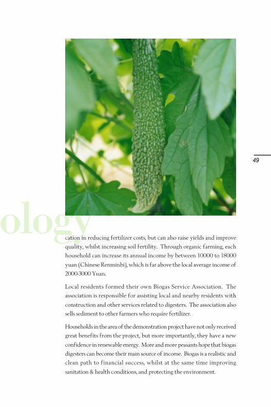
49
ologycation in reducing fertilizer costs, but can also raise yields and improve
quality, whilst increasing soil fertility. Through organic farming, each
household can increase its annual income by between 10000 to 18000
yuan (Chinese Renminbi), which is far above the local average income of
2000-3000 Yuan.
Local residents formed their own Biogas Service Association. The
association is responsible for assisting local and nearby residents with
construction and other services related to digesters. The association also
sells sediment to other farmers who require fertilizer.
Households in the area of the demonstration project have not only received
great benefits from the project, but more importantly, they have a new
confidence in renewable energy. More and more peasants hope that biogas
digesters can become their main source of income. Biogas is a realistic and
clean path to financial success, whilst at the same time improving
sanitation & health conditions, and protecting the environment.
CO
NTA
CT
GEI would like to thank the following organizations
for supporting this project:
Blue moon foundToyota Environmental Activities Grant Program
of Toyota Motor CorporationTianheng Institute
Fei NieEr Corporation
For further technical information, please contact :
Global Environmental InstitutePhone: +86 10 6708 3192
Fax: +86 10 6708 3192
Technical Advisor: Sun Jinshi
Wang YanjiaEditor: Jin Jiaman
Chen Zhiping
Cui NanyingSu Tao
Racher Enslow
Translator: Thomas Bywater