biosand filter manual - itacanet.org · biosand filter manual design, construction, installation,...
TRANSCRIPT

BIOSAND FILTER MANUAL
Design, Construction, Installation, Operation and Maintenance
January 2008

COMPILED AND PUBLISHED BY:
BAY 12, 2916 – 5TH AVENUE
CALGARY, ALBERTA CANADA, T2A 6K4
PHONE + 1 (403) 243-3285 FAX + 1 (403) 243-6199
E-MAIL: [email protected] WEB: WWW.CAWST.ORG
CAWST and its employees, contractors, directors, and volunteers do not assume any
responsibility for and make no warranty with respect to the results that may be obtained from the
use of the information provided. Under ideal circumstances, the biosand filter can produce
drinking water of high quality. However, this cannot always be assured or guaranteed due to
variations in the construction and installation of the filter. CAWST shall not be liable to anyone
whatsoever for any damage resulting from reliance on any information provided in the document
or attachments thereto. This also applies to the consumption of water from the biosand filter. It
should be noted that the biosand filter cannot be relied upon to remove certain or all forms of
water contamination.
CAWST and the authors hereby provide permission to reproduce all or portions of this manual
with the intention of increasing the availability to those who need it. CAWST welcomes enquires
from any individual or organization wishing to use any material from this manual for non-
commercial purposes.
Cover photos: Left photo courtesy of South Asia Pure Water Initiative, Inc. (pictured: young girl in India). Right photo courtesy of Tommy Ngai (pictured: Ganesh Harijan, Nepal)
January 2008 1
PREFACE The Centre for Affordable Water and Sanitation Technology (CAWST) is a registered Canadian charity
that provides professional services - training, education, and technical consulting in water and sanitation -
to organizations and individuals that serve the poor in developing countries.
Improving water quality at the household level, with point-of-use technologies such as the biosand filter,
has proven to be effective in reducing health risks and rates of water-related diseases among end users.
This manual is a tool that can be used in training courses on the biosand filter. It is a practical reference
guide for project implementers, trainers, product manufacturers, and community health workers involved in
promoting the biosand filter for household water treatment in developing countries.
Specifically, this manual is designed for CAWST clients, including local non-governmental organizations
(NGOs), multinational NGOs, governments, research institutions, private sector organizations and
individuals.
The manual illustrates the design, construction, installation, operation and maintenance of the biosand
filter. It provides a) background information to understand how the biosand filter works, b) step-by-step
instructions, and c) checklists and forms that can be used throughout the production, installation and
follow-up process.
For further information on CAWST training programs and professional services in water and sanitation
please visit our website at www.cawst.org.

January 2008 2
TABLE OF CONTENTS
ACRONYMS............................................................................................................................ 3 UNIT CONVERSIONS............................................................................................................ 3 INTRODUCTION TO CAWST............................................................................................... 4 OVERVIEW OF THE BIOSAND FILTER............................................................................. 5 THE FILTRATION PROCESS................................................................................................ 8 PATHOGEN REMOVAL ...................................................................................................... 10 ARSENIC REMOVAL........................................................................................................... 11 ADVANTAGES OF THE BIOSAND FILTER..................................................................... 12 BIOSAND FILTER OPERATION ........................................................................................ 13 SUMMARY OF CONTAMINANT REMOVAL EFFICIENCY .......................................... 16 CONSTRUCTION SAFETY ................................................................................................. 17 FILTER TOOL KIT................................................................................................................ 18 TOOLS AND MATERIALS .................................................................................................. 17 MATERIALS LIST ................................................................................................................ 19 FLOW CHART FOR BIOSAND FILTER CONSTRUCTION............................................. 21 APPENDIX A: STEEL MOLD FABRICATION .................................................................. 22 APPENDIX B: SIEVE SET CONSTRUCTION.................................................................... 42 APPENDIX C: MEDIA PREPARATION ............................................................................. 44 APPENDIX D: CONCRETE FILTER CONSTRUCTION ................................................... 49 APPENDIX E : DIFFUSER AND LID.................................................................................. 58 APPENDIX F: INSTALLATION, OPERATION, AND MAINTENEANCE ...................... 66 APPENDIX G: FILTER CONSTRUCTION CHECKLIST .................................................. 77 APPENDIX H: QUALITY CONTROL CHECKLIST .......................................................... 78 APPENDIX I: INSTALLATION CHECKLIST .................................................................... 79 APPENDIX J: FILTER PRODUCTION RECORD .............................................................. 80 APPENDIX K: COSTING AND PRICING FORM (1)......................................................... 81 APPENDIX L: COSTING AND PRICING FORM (2) ......................................................... 82 APPENDIX M: FILTER CONSTRUCTION MONITORING.............................................. 83 APPENDIX N: HOUSEHOLD MONITORING ................................................................... 85 APPENDIX O: SAND SIEVE ANALYSIS........................................................................... 87
January 2008 3
ACRONYMS
CAWST Centre for Affordable Water and Sanitation Technology
CEO Chief Executive Officer
ES effective size
HWT household water treatment
HTH high test hypochlorite
ID inner diameter
NADCC sodium dichloroisocyanurate
NGO non-governmental organization
NTU nephelometric turbidity units
QTY quantity
SODIS solar disinfection
UC uniformity coefficient
UN United Nations
UV ultraviolet
UNIT CONVERSIONS
Length or Distance 1 foot = 0.30 metres 1 inch = 2.54 cm 1 mm = 0.1 cm
1 metre = 3.28 feet 1 cm = 0.39 inches 1 cm = 10 mm
Volume or Area
1 gallon = 3.78 litres
1litre = 0.26 gallons
cm centimetre m metre
ft foot min minute
kg kilogram mm millimetre
L litre ‘ foot
lb pound “ inch

January 2008 4
INTRODUCTION TO CAWST The History Recognizing it as an ideal option for developing country applications, Dr. David Manz, a professor from the University of Calgary, developed the biosand filter in the early 1990’s to provide inexpensive, safe, drinking water for communities in developing countries. The Centre for Affordable Water and Sanitation Technology (CAWST) was co-founded in 2001 by current President and Chief Executive Officer (CEO), Camille Dow Baker, and Dr. Manz to answer the question, “How can we get proven technologies in the hands of the millions that need safe water?" The CAWST Model CAWST started with the belief that the poor in the developing world deserve safe water and basic sanitation. CAWST also believes that the place to start is to teach people the skills necessary to have safe water in their homes. The goal of the CAWST model is to pass knowledge and skills to organizations and individuals in developing countries through education, training and consulting services. They, in turn, can motivate households to take action and meet their own water and sanitation needs. CAWST’s main strategies are to: • Make knowledge about water “common knowledge”; • Build the capacity of local public sector organizations, both NGOs and government agencies; • Focus on household water treatment (HWT); • Lead with the education and training; and • Identify barriers to implementation of water and sanitation projects and ways to overcome them. This approach: • Empowers, motivates and generates grass roots action within the community; • Provides opportunities for continuous learning and support; • Generates multiple, independent actions required to reach the United Nations (UN) Millennium
Development Goals for water and sanitation; and • Has received growing international recognition:
Ernst & Young Entrepreneur of the Year Award, Special Recognition, Canada (2007). Special Consultative Status, UN Economic and Social Council (2006). Kyoto World Water Grand Prize, Finalist, Mexico (2006). Water Action Competition, Top 10 Finalist, World Water Forum, Kyoto (2003). Best Practice to Improve the Living Environment, Top 40 Finalist, UN Habitat (2004).
For further information about our results and global impact, please visit www.cawst.org/index.php?id=64.
January 2008 5
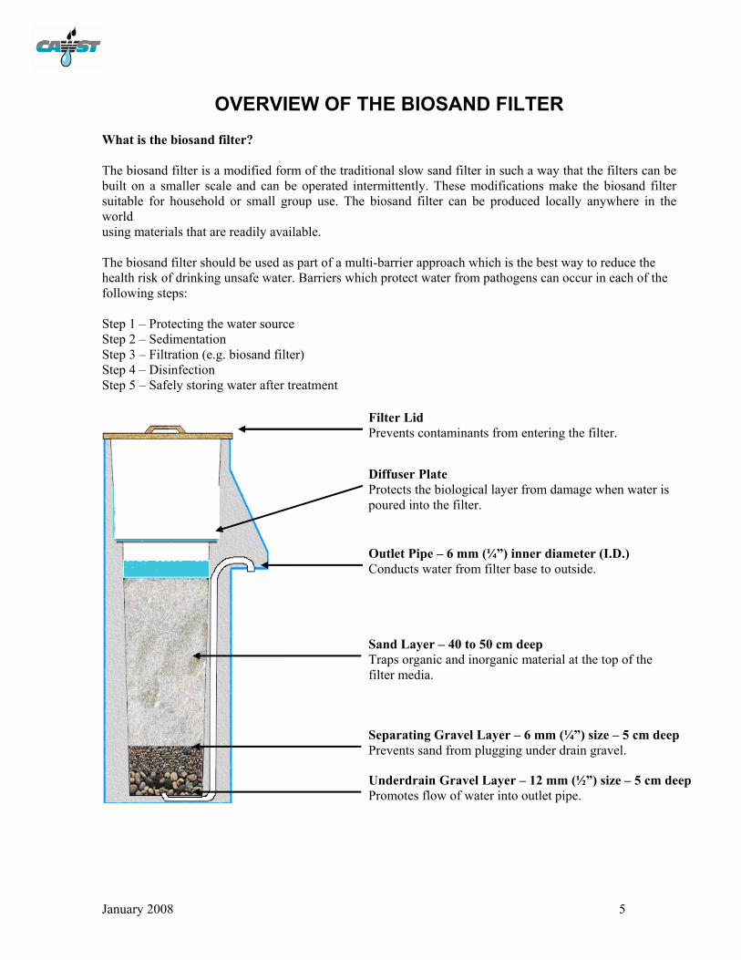
OVERVIEW OF THE BIOSAND FILTER What is the biosand filter? The biosand filter is a modified form of the traditional slow sand filter in such a way that the filters can be built on a smaller scale and can be operated intermittently. These modifications make the biosand filter suitable for household or small group use. The biosand filter can be produced locally anywhere in the world using materials that are readily available. The biosand filter should be used as part of a multi-barrier approach which is the best way to reduce the health risk of drinking unsafe water. Barriers which protect water from pathogens can occur in each of the following steps: Step 1 – Protecting the water source Step 2 – Sedimentation Step 3 – Filtration (e.g. biosand filter) Step 4 – Disinfection Step 5 – Safely storing water after treatment
Separating Gravel Layer – 6 mm (¼”) size – 5 cm deep Prevents sand from plugging under drain gravel.
Diffuser Plate Protects the biological layer from damage when water is poured into the filter.
Filter Lid Prevents contaminants from entering the filter.
Sand Layer – 40 to 50 cm deep Traps organic and inorganic material at the top of the filter media.
Outlet Pipe – 6 mm (¼”) inner diameter (I.D.) Conducts water from filter base to outside.
Underdrain Gravel Layer – 12 mm (½”) size – 5 cm deep Promotes flow of water into outlet pipe.
January 2008 6
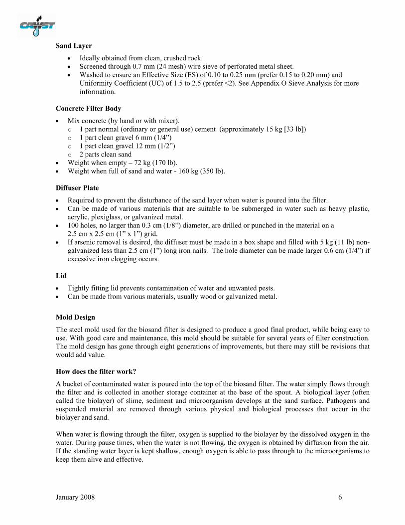
Sand Layer
• Ideally obtained from clean, crushed rock. • Screened through 0.7 mm (24 mesh) wire sieve of perforated metal sheet. • Washed to ensure an Effective Size (ES) of 0.10 to 0.25 mm (prefer 0.15 to 0.20 mm) and
Uniformity Coefficient (UC) of 1.5 to 2.5 (prefer <2). See Appendix O Sieve Analysis for more information.
Concrete Filter Body
• Mix concrete (by hand or with mixer). o 1 part normal (ordinary or general use) cement (approximately 15 kg [33 lb]) o 1 part clean gravel 6 mm (1/4”) o 1 part clean gravel 12 mm (1/2”) o 2 parts clean sand
• Weight when empty – 72 kg (170 lb). • Weight when full of sand and water - 160 kg (350 lb). Diffuser Plate
• Required to prevent the disturbance of the sand layer when water is poured into the filter. • Can be made of various materials that are suitable to be submerged in water such as heavy plastic,
acrylic, plexiglass, or galvanized metal. • 100 holes, no larger than 0.3 cm (1/8”) diameter, are drilled or punched in the material on a
2.5 cm x 2.5 cm (1” x 1”) grid. • If arsenic removal is desired, the diffuser must be made in a box shape and filled with 5 kg (11 lb) non-
galvanized less than 2.5 cm (1”) long iron nails. The hole diameter can be made larger 0.6 cm (1/4”) if excessive iron clogging occurs.
Lid
• Tightly fitting lid prevents contamination of water and unwanted pests. • Can be made from various materials, usually wood or galvanized metal.
Mold Design
The steel mold used for the biosand filter is designed to produce a good final product, while being easy to use. With good care and maintenance, this mold should be suitable for several years of filter construction. The mold design has gone through eight generations of improvements, but there may still be revisions that would add value. How does the filter work?
A bucket of contaminated water is poured into the top of the biosand filter. The water simply flows through the filter and is collected in another storage container at the base of the spout. A biological layer (often called the biolayer) of slime, sediment and microorganism develops at the sand surface. Pathogens and suspended material are removed through various physical and biological processes that occur in the biolayer and sand. When water is flowing through the filter, oxygen is supplied to the biolayer by the dissolved oxygen in the water. During pause times, when the water is not flowing, the oxygen is obtained by diffusion from the air. If the standing water layer is kept shallow, enough oxygen is able to pass through to the microorganisms to keep them alive and effective.
January 2008 7
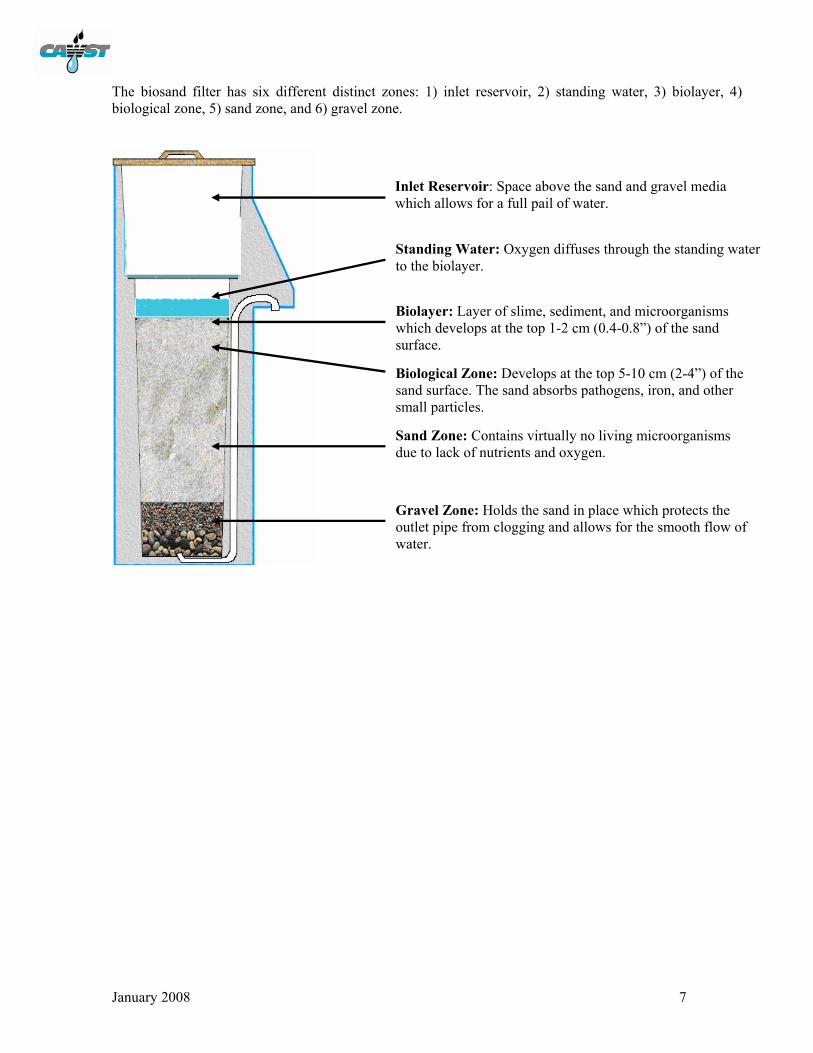
The biosand filter has six different distinct zones: 1) inlet reservoir, 2) standing water, 3) biolayer, 4) biological zone, 5) sand zone, and 6) gravel zone.
Standing Water: Oxygen diffuses through the standing water to the biolayer.
Biolayer: Layer of slime, sediment, and microorganisms which develops at the top 1-2 cm (0.4-0.8”) of the sand surface.
Biological Zone: Develops at the top 5-10 cm (2-4”) of the sand surface. The sand absorbs pathogens, iron, and other small particles.
Sand Zone: Contains virtually no living microorganisms due to lack of nutrients and oxygen.
Gravel Zone: Holds the sand in place which protects the outlet pipe from clogging and allows for the smooth flow of water.
Inlet Reservoir: Space above the sand and gravel media which allows for a full pail of water.
January 2008 8
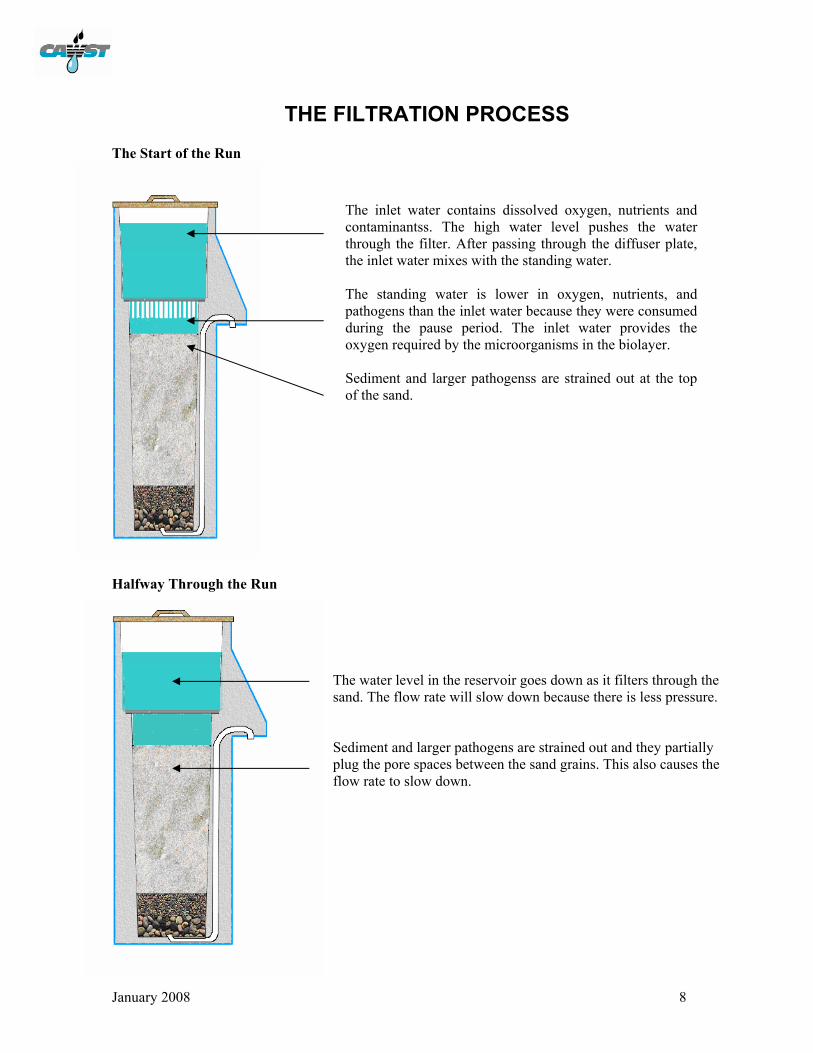
THE FILTRATION PROCESS The Start of the Run
Halfway Through the Run
The water level in the reservoir goes down as it filters through the sand. The flow rate will slow down because there is less pressure. Sediment and larger pathogens are strained out and they partially plug the pore spaces between the sand grains. This also causes the flow rate to slow down.
The inlet water contains dissolved oxygen, nutrients and contaminantss. The high water level pushes the water through the filter. After passing through the diffuser plate, the inlet water mixes with the standing water. The standing water is lower in oxygen, nutrients, and pathogens than the inlet water because they were consumed during the pause period. The inlet water provides the oxygen required by the microorganisms in the biolayer. Sediment and larger pathogenss are strained out at the top of the sand.

January 2008 9
The End of the Run
The Pause Period
The water flow finally stops. The standing water layer will be at the same height as the outlet of the pipe. Pathogens in the inlet water are consumed and those from the previous run which were partially consumed are more completely broken down. Pathogen removal increases with time because of the slower flow rate and the decreased size of pore openings.
Some oxygen from the air passes through the standing water to the biolayer. The pause period allows time for microorganisms in the biolayer to consume the nutrients and pathogens in the water. The flow rate through the filter is restored as they are consumed. If the pause period is too long, the biolayer will eventually consume all of the pathogens and nutrients and eventually die off. This will reduce the removal efficiency of the filter when it is used again. A 6 to 12 hour pause period is recommended with a minimum of 1 hour and a maximum of 48 hours. Microorganisms in the sand zone die off due to the lack of nutrients and oxygen.

January 2008 10
PATHOGEN REMOVAL The biosand filter bed is constructed with three types of media: sand, separating gravel, and underdrain gravel. When a bucket of contaminated water is poured into the top of biosand filter, the water simply flows through the different media layers. There are four processes that remove pathogens as the water passes through the filter. A. Mechanical trapping Sediment and pathogens are physically trapped in the spaces between sand grains. B. Predation Pathogens are consumed by other microorganisms in the standing water and biolayer. C. Adsorption/Attraction Pathogens become attached to each other, sediment, and the sand grains. D. Natural death Pathogens finish their life cycle or die because there is not enough food and oxygen for them to survive. Biosand filters have been shown to remove 90-99% of pathogens found in water. The filter has been tested by various government, research, and health institutions, as well as by non-governmental agencies in both laboratory and field settings. Overall, these studies have shown that the biosand filter removes:
• > 97% of E. coli - an indicator of fecal contamination (Duke, 2006; Stauber, 2006) • > 99% of protozoa and helminths (Palmateer, 1999) • 80-90% of viruses (Stauber, 2005) • 50-90% of organic and inorganic toxicants (Palmateer, 1999) • 90-95% of iron (Ngai, 2007) • Most suspended sediments
Based on slow sand filter research, the biosand filter may also remove some heavy metals (Muhammad, 1997; Collins, 1998). There is also a design modification known as the KanchanTM Arsenic Filter that is effective in removing both pathogens and 85-90% of arsenic from source water (Ngai, 2007).
Preliminary health impact studies estimate a 30-40% reduction in diarrhea among all age groups, including children under the age of five, an especially vulnerable population (Liang, 2007; Sobsey, 2007).
January 2008 11
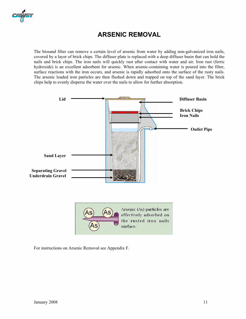
ARSENIC REMOVAL The biosand filter can remove a certain level of arsenic from water by adding non-galvanized iron nails, covered by a layer of brick chips. The diffuser plate is replaced with a deep diffuser basin that can hold the nails and brick chips. The iron nails will quickly rust after contact with water and air. Iron rust (ferric hydroxide) is an excellent adsorbent for arsenic. When arsenic-containing water is poured into the filter, surface reactions with the iron occurs, and arsenic is rapidly adsorbed onto the surface of the rusty nails. The arsenic loaded iron particles are then flushed down and trapped on top of the sand layer. The brick chips help to evenly disperse the water over the nails to allow for further absorption.
For instructions on Arsenic Removal see Appendix F.
Diffuser Basin
Brick Chips Iron Nails
Outlet Pipe
Lid
Sand Layer
Separating Gravel Underdrain Gravel

January 2008 12
ADVANTAGES OF THE BIOSAND FILTER Functional
The biosand filter is a ‘point of use’ or household treatment device. Water can be obtained from the closest water supply point, whether that is a river, a stream or a well, and used immediately after filtering. The water supply, treatment, and distribution are all within the control of the individual householder. Effective use of the technology does not require user groups or other community support which are sometimes difficult to develop and sustain. The independence of the household makes this technology extremely suitable for developing countries which often lack the governance and regulatory processes needed for effective and efficient community water systems. High User Acceptability
The biosand filter is easy to use and it improves the look and taste of water. As well, the filter takes up very little space and can easily fit into most rooms. In fact, previous experience has shown that the filter normally occupies a place of significance in the living room because it is so important to the individual household. User-friendly
It is simple to operate and maintain the filter. There are no moving parts that require skill to operate. When the water flow through the filter becomes too slow, the maintenance consists simply of washing the top few centimetres of sand. Operating and maintaining the filter is well within the capacity of the household users. Durable
The filter box is made of cement concrete with a built-in pipe. It is very durable since there are no moving parts during operation. The filter may need occasional replacement of iron nails (e.g. for arsenic removal) or wooden components (e.g. the lid) that may deteriorate over time. Sufficient Water Quantity
The recommended flow rate for a biosand filter is 0.6 L/minute (measured when the filter box is full of water). Based on this flow rate and the time required for pause periods, the biosand filter can effectively treat 60-80 L/day. Affordable
The cost of a concrete biosand water filter varies from country to country and ranges from US$12-30 depending on the material and labour costs. Its main components (concrete, sand and gravel) are readily available in all developing countries. Manufacturing the filters involves a significant amount of manual labour to mix the concrete and pour it into the filter mold. The skills required to do this are readily available in developing countries at a very low cost. The labour can also be provided by the individual home owner. Limitations
The biosand filter cannot remove some dissolved substances (e.g. salt, hardness), some organic chemicals (e.g., pesticides and fertilizers), or color, and cannot guarantee that the water is pathogen free. The biosand filter should be used as part of the multi-barrier approach for providing safe water. Similar to other types of water filters, it is recommended to disinfect the water after it has passed through the biosand filter.

January 2008 13
BIOSAND FILTER OPERATION Water Source
The biosand filter can use any water source such as rainwater, deep groundwater, shallow groundwater, rivers, lakes or other surface waters. The source should be the cleanest available since the filter is only able to remove a certain percent of the pathogens. If the source water is highly contaminated, the outlet water may still have some contaminants. The same source of water should be used consistently because the biolayer cannot quickly adapt to different water quality. Over time, the microorganisms in the biolayer become used to a certain amount of contamination from the source water. If different source water with a higher level of contamination is used, the biolayer may not be able to consume all of the pathogens. It may take the biolayer several days to adapt to the new source water and level of contamination. Experiments have shown that the largest portion of bacteria from a more contaminated source water show up in the filtered water the next day (see Summary Table: Contaminant Removal Efficiency of the Biosand Filter; Buzanis 1995). The turbidity (cloudiness in water) of the source water is also a key factor in the operation of the filter. Nephelometric turbidity units (NTU) measure the level of suspended matter (organic and silt particles) in water. If the turbidity is greater than 50 NTU, the source water should be settled or strained before it goes though the biosand filter. A simple test to measure the turbidity is to use a 2 litre clear plastic soft drink bottle filled with the source water. Place this on top of large print such as the CAWST logo on this manual. If you can see this logo looking down through the top of the bottle, the water probably has a turbidity of less than 50 NTU. Establishing the Biolayer
The biolayer is the key pathogen removing component of the filter. Without it, the filter removes some contamination through screening of the sediment and microorganisms (only 30-70% removal efficiency). The ideal biolayer will remove 90-99% of pathogens. It may take up to 30 days to establish the biolayer. During that time, both the removal efficiency and the oxygen demand will increase as the biolayer grows. The biolayer is NOT usually visible – it is not a green slimy coating on top of the sand. The water from the filter can be used during the first few weeks while the biolayer is being established, but disinfection, as always, is recommended during this time. Figure 1 illustrates how the biolayer is established. The process may vary as some filters require a shorter or longer period of time to establish the biolayer depending on the source of water being used.
Figure 1 Establishing the Biolayer
Time Required (days)
Pathogen Removal
Efficiency (%)
99
30
After cleaning, the removal efficiency declines somewhat, but returns to its previous level as the biolayer is re-established.
The removal efficiency will vary as the biolayer develops.

January 2008 14
Flow Rate
The biosand filter has been designed to allow for a filter loading rate (flow rate per square metre of filter area) which has proven to be effective in laboratory and field tests. This filter loading rate has been determined to be not more than 600 litres/hour/square metre. The recommended flow rate for the standard concrete biosand filter shown in this manual is 0.6 L/minute measured when the inlet reservoir is full of water. If the flow rate is much faster, the filter may become less efficient at removing pathogens. If the flow rate is much slower, the household user may become impatient and not use the filter at all even though the filter is working well at removing pathogens. Since the flow rate is controlled by the size of the sand grains, it is very important to select and prepare the sand according to the instructions provided in Appendix B. Pause Period
The biosand filter is most effective and efficient when operated intermittently and consistently. A recommended pause period is 6 to 12 hours with a minimum of 1 hour and a maximum of 48 hours. The pause period is important because it allows time for the microorganisms in the biolayer to consume the pathogens in the water. As the pathogens are consumed, the flow rate through the filter may be restored. If the pause period is extended for too long, the microorganisms will eventually consume all of the nutrients and pathogens and then eventually die off. This will reduce the removal efficiency of the filter when it is used again. Water Depths
Correct installation and operation of the biosand filter has a water level of approximately 5 cm (2”) above the sand during the pause period. A water depth of greater than 5 cm (2”) results in lower oxygen diffusion and consequently a thinner biological zone. A high water level can be caused by a blocked outlet pipe or by an insufficient amount of sand. A water depth less than 5 cm (2”) may evaporate quickly in hot climates and cause the biolayer to dry out. Filtered Water Quality
The final step in household water treatment is to remove, deactivate or kill any remaining pathogens in the filtered water through disinfection. There are various methods that are used by households around the world to disinfect their drinking water: chemical disinfection, solar disinfection, boiling, pasteurization, and ultraviolet disinfection. Chemical Disinfection Chlorination is the most widely used method for disinfecting drinking water. Disinfecting water with chlorine will kill bacteria and viruses, but it does not deactivate parasites like giardia, cryptosporidium and worm eggs. Chlorine can be found in different forms: • sodium hypochlorite (eg. household bleach) • sodium dichloroisocyanurate (NADCC), marketed under the trade name of Aquatabs or others • calcium lime, sometimes referred to as chlorinated lime (eg. bleaching powder) • calcium hypochlorite, also known as high test hypochlorite (HTH) used in products such as PUR
January 2008 15
Chlorine must be added in sufficient quantities to destroy all pathogens, but not so much that taste is adversely affected. Determining the right amount can be difficult because substances in the water will react with the disinfectant, and the strength of the disinfectant may decline over time depending on how it is stored. Also, it is important to know the strength of the chlorine product since they can vary from 0.5 to 70% available chlorine. Solar Water Disinfection (SODIS) SODIS is a simple and low-cost technology that uses solar radiation and temperature to destroy pathogenic bacteria and viruses present in water. Its efficiency in killing protozoa depends on the water temperature reached during solar exposure. SODIS is ideal to treat small quantities of water. Water is filled into transparent plastic bottles and exposed to full sunlight for six hours. Boiling Boiling water at 100oC will kill most pathogens and many are killed at 70 degrees celsius. The recommended boiling time is one minute at sea level, adding one minute for every additional 1000 metres in altitude. The main disadvantages of boiling water are that is uses up fuel and it is time consuming, making it environmentally and economically unsustainable. As well, boiling water in the home can also contribute to poor indoor air quality and lead to respiratory health issues. Pasteurization Pasteurization is the process of disinfecting water by heat or radiation. Water pasteurization achieves the same effect as boiling, but at a lower temperature of 70-75 degrees celsius over a longer period of time. A thermometre or indicator is needed to tell when the pasteurization temperature is reached. A simple method of pasteurizing water is to simply put blackened containers of water in a solar box cooker, an insulated box made of wood, cardboard, plastic, or woven straw. Common solar box cookers can pasteurize water at a rate of about 1 litre per hour. Ultraviolet (UV) Disinfection UV disinfection works by disabling the DNA of the microorganisms in the water. The microorganisms soon die since they are unable to replicate. There are various manufacturers of commercial and household UV systems. All of them require some a source of electricity (for example, battery, solar power) and some of these systems can be expensive. Maintenance
Over time, the pore opening between the sand grains will become clogged with sediment. As a result, the water flow rate through the filter will slow down. To clean the filter, the surface of the sand must be agitated to re-suspend the sediment in the standing water. The dirty water can be removed using a small container. The process can be repeated as many times as necessary to regain the desired flow rate. After cleaning, it will take the biolayer up to a week to re-establish itself and return the removal efficiency to its previous level, see Figure 1.

January 2008 16
SUMMARY TABLE: CONTAMINANT REMOVAL
SUMMARY OF CONTAMINANT REMOVAL EFFICIENCY Country Author(s) Organization(s) Year Contaminants Reported
Removal Efficiency
E. coli 95% Cambodia Liang, K. Sobsey, MD
University of North Carolina
2007
Turbidity 82% Nicaragua Vanderzwaag, J. University of British
Columbia 2007
E. coli 97%
E. coli 95-98% Dominican Republic
Stauber, C. Elliot, M.
University of North Carolina
2006
Viruses 80-90%
E. coli 98.5% Haiti Duke, W.
Baker, D.
University of Victoria, BC; CAWST
2006
Turbidity 85%
E. coli 87.9% Ethiopia Earwater, P.
Cranfield University Silsoe
2006 Turbidity 81.2% E. coli 97% Ethiopia *Samaritan’s Purse 2006 Turbidity 80%
Kenya, Mozambique Cambodia, Vietnam, Honduras, Nicaragua
Kaiser, N. Liang, K. Maertens, M. Snider, R.
Samaritan’s Purse Canada
2002
Fecal coliform 93%
Nepal Lee, T. Massachusetts Institute of Technology (MIT)
2001 E. coli 83%
Fecal coliform (after 21 days) 97% Nicaragua Manz. D
Buzunis, B. Morales, C.
University of Calgary
1993
Fecal coliform (after 2 months) 96.4%
*This study was an internal study conducted by Samaritan’s Purse and will not be published.
Health Impact Studies
Country Organization Year Results Dominican Republic†
University of North Carolina
2007 For all ages including children under 5, there was a 30-40% reduction in the number of cases of diarrhea
Cambodia† University of North Carolina
2007 For children under 5 and adults, there was a 44% reduction in the number of cases of diarrhea. The greatest reduction of diarrhea (46%) occurred in children ages 2-4.
† These studies are preliminary findings and are expected to be published in 2008.

January 2008 17
CONSTRUCTION SAFETY It is important to work safely and avoid the potential for injury while constructing a biosand filter. You will be using sharp tools, lifting heavy pieces, and handling potentially dangerous materials. When properly managed, the risks involved in these tasks can be reduced to avoid injuries. The work place should have a first aid kit available at all times. As a minimum, it should be stocked with band aids and disinfectant materials. Medical assistance contact numbers should be readily available. Cement and Concrete
Cement can hurt you by contacting your skin, contacting your eyes, or being inhaled. Cement usually contains a metal called hexavalent chromium. This metal causes allergic dermatitits (inflammation of the skin). When you empty a bag of cement, the dust can irritate your skin. The dust reacts with sweat or damp clothing to form a corrosive solution. Cement dust can also get in your eyes, causing redness, burns, or blindness. Inhaling cement dust irritates your nose and throat. It can also cause choking and trouble breathing. Cement is also hazardous when it’s wet—in mortar or concrete. If it gets inside your boots or gloves, or soaks through your clothes, it can cause burns and skin ulcers. The burns caused by cement may be slow. You may not feel anything until several hours later. That’s why it’s important to wash cement off your skin right away. What to wear: • Wear eye protection for mixing, pouring, and other work with dry cement. • Wear gloves. • Wear long sleeves and full-length pants. • Pull sleeves over gloves. • When working with wet mortar or concrete, tuck pants inside boots. What to do: • Work upwind from cement dust. • Remove rings and watches because cement dust can collect underneath and burn your skin. • Remove any clothing contaminated by cement. • When your skin comes in contact with cement, wash with cold running water as soon as possible. Flush
out any open sores or cuts. Get medical attention if your skin still feels like it’s burning. • After working with cement, always wash your hands before eating, smoking, or using the toilet. • If your eyes are exposed to cement, rinse with cold clean water for at least 15 minutes. Get medical
attention if necessary.
Chlorine
Chlorine on your skin may cause irritation unless it is rinsed off immediately and flushed with large amounts of water. Any contaminated clothing should be removed and washed before being reused. Chlorine that gets in your eyes may cause inflammation of your throat, nose and lungs. If your eyes are exposed to chlorine, rinse with clean water for at least 15 minutes while lifting the upper and lower lids occasionally. It is also advised to get medical attention. Tools
While all of the tools used to construct the filter are small hand tools, they still have a potential to cause injury. Safely storing and using the tools correctly is the best way to prevent injuries. Use caution with sharp tools (saws, tin snips and knives) to prevent cuts. Sharp edges of metal sheets can also cause cuts. Be aware of smashing and crushing injuries to hands when using hammers and wrenches.

January 2008 18
FILTER TOOL KIT A good set of tools is needed to easily and properly construct a biosand filter. These are all hand tools and, if maintained and handled properly, will provide many years of useful life. The following tools are needed for constructing the sand sieves, lids, and diffusers:
Nails – 1 kg of 2.5 cm (1”) nails Nails – 1 kg of 5 cm (2”) nails Sand paper Tape measure T-square
Hand saw Hammer Tin snips Utility knife Acrylic cutter knife
The following tools are needed for constructing the concrete filter:
Wire brush and scraper Sand paper Hack saw with spare blades / pipe cutters Trowel (or small piece of wood) 14 mm (9/16”)open/box end wrenches, qty 2;
[a 14mm (9/16”) socket set may also be used] Level
Rubber hammer 38 mm (1.5”) open/box end wrench or pipe
wrench or large adjustable wrench Tool box Shovels Pails (12–16 litres volume), qty 4-6
Supplemental items:
Coarse bristle brush 2.5 cm (1”) scraper Small container 1 m (3.5’) hollow steel pipe with 5cm (2”)
diameter 1 litre marked container
Rubber gloves Leather gloves Duct tape 1.5 m (5’) metal rod (such as rebar) or piece
of wood
Optional tools:
Stapler Wire Hand drill and bits Flat headed screw driver 15 cm (6”) slip joint pliers 5 cm (2”) paint brush
8 cm (3”) paint brush Wheelbarrow 1 cm (3/8”) copper pipe bender Copper pipe cutter

January 2008 17
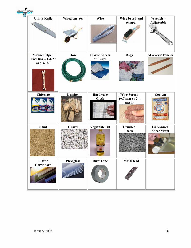
TOOLS AND MATERIALS
Acrylic Cutter Knife
Bristle Brush
Copper pipe bender
Copper pipe cutter
Gloves - Leather
Gloves - Rubber
Hack saw and blades
Hammer - Common
Hammer - Rubber
Hand Drill
Hand Saw
Hollow Pipe
Level
1 litre measured container
Nails – 2.5-5cm (1- 2”)
Pails
Paintbrushes – 5-7.5cm (2-3”)
Pliers – slip joint
Sand Paper
Scraper – 2.5cm (1”)
Screwdriver – flat head/slot
head
Shovels
Small Containers
Socket – 9/16”
Stapler
Tape Measure
Tin snips
Tool Box
Trowel
T-Square
January 2008 18
Utility Knife
Wheelbarrow
Wire
Wire brush and scraper
Wrench – Adjustable
Wrench Open End Box – 1-1/2”
and 9/16”
Hose
Plastic Sheets or Tarps
Rags
Markers/ Pencils
Chlorine
Lumber
Hardware Cloth
Wire Screen (0.7 mm or 24
mesh)
Cement
Sand
Gravel
Vegetable Oil
Crushed Rock
Galvanized Sheet Metal
Plastic
Cardboard
Plexiglass
Duct Tape
Metal Rod
January 2008 19
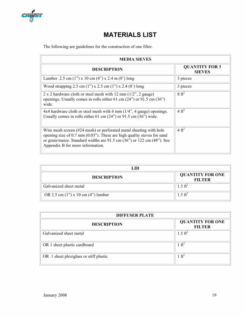
MATERIALS LIST The following are guidelines for the construction of one filter.
MEDIA SIEVES
DESCRIPTION QUANTITY FOR 3 SIEVES
Lumber 2.5 cm (1”) x 10 cm (4”) x 2.4 m (8’) long 3 pieces
Wood strapping 2.5 cm (1”) x 2.5 cm (1”) x 2.4 (8’) long 3 pieces
2 x 2 hardware cloth or steel mesh with 12 mm (1/2”, 2 gauge) openings. Usually comes in rolls either 61 cm (24”) or 91.5 cm (36”) wide.
8 ft2
4x4 hardware cloth or steel mesh with 6 mm (1/4”, 4 gauge) openings. Usually comes in rolls either 61 cm (24”) or 91.5 cm (36”) wide.
4 ft2
Wire mesh screen (#24 mesh) or perforated metal sheeting with hole opening size of 0.7 mm (0.03”). These are high quality sieves for sand or grain/maize. Standard widths are 91.5 cm (36”) or 122 cm (48”). See Appendix B for more information.
4 ft2
LID
DESCRIPTION QUANTITY FOR ONE FILTER
Galvanized sheet metal 1.5 ft2
OR 2.5 cm (1”) x 10 cm (4”) lumber 1.5 ft2
DIFFUSER PLATE
DESCRIPTION QUANTITY FOR ONE FILTER
Galvanized sheet metal 1.5 ft2
OR 1 sheet plastic cardboard 1 ft2
OR 1 sheet plexiglass or stiff plastic
1 ft2
January 2008 20
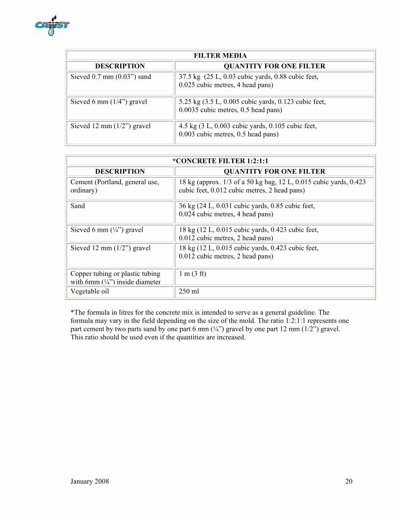
FILTER MEDIA DESCRIPTION QUANTITY FOR ONE FILTER
Sieved 0.7 mm (0.03”) sand 37.5 kg (25 L, 0.03 cubic yards, 0.88 cubic feet, 0.025 cubic metres, 4 head pans)
Sieved 6 mm (1/4”) gravel 5.25 kg (3.5 L, 0.005 cubic yards, 0.123 cubic feet, 0.0035 cubic metres, 0.5 head pans)
Sieved 12 mm (1/2”) gravel 4.5 kg (3 L, 0.003 cubic yards, 0.105 cubic feet, 0.003 cubic metres, 0.5 head pans)
*CONCRETE FILTER 1:2:1:1
DESCRIPTION QUANTITY FOR ONE FILTER Cement (Portland, general use, ordinary)
18 kg (approx. 1/3 of a 50 kg bag, 12 L, 0.015 cubic yards, 0.423 cubic feet, 0.012 cubic metres, 2 head pans)
Sand 36 kg (24 L, 0.031 cubic yards, 0.85 cubic feet, 0.024 cubic metres, 4 head pans)
Sieved 6 mm (¼”) gravel 18 kg (12 L, 0.015 cubic yards, 0.423 cubic feet, 0.012 cubic metres, 2 head pans)
Sieved 12 mm (1/2”) gravel 18 kg (12 L, 0.015 cubic yards, 0.423 cubic feet, 0.012 cubic metres, 2 head pans)
Copper tubing or plastic tubing with 6mm (¼”) inside diameter
1 m (3 ft)
Vegetable oil 250 ml
*The formula in litres for the concrete mix is intended to serve as a general guideline. The formula may vary in the field depending on the size of the mold. The ratio 1:2:1:1 represents one part cement by two parts sand by one part 6 mm (¼”) gravel by one part 12 mm (1/2”) gravel. This ratio should be used even if the quantities are increased.

January 2008 21
FLOW CHART FOR BIOSAND FILTER CONSTRUCTION
Obtain gravel and sand
Appendix C
Prepare the media
Appendix C
Construct sieve set
Appendix B
Construct diffuser and lid
Appendix E
Prepare mold and mix concrete
Appendix D
Pour filter
Appendix D
Wait 18 – 24 hours
Remove filter from mold
Appendix D
Install filter, test flow, disinfect spout
Appendix F
Steel mold fabrication Appendix A
Wash sand and gravel used for
media filter
Appendix C
January 2008 22
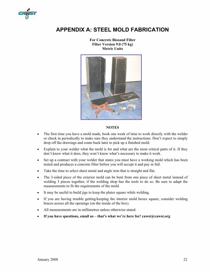
APPENDIX A: STEEL MOLD FABRICATION For Concrete Biosand Filter
Filter Version 9.0 (75 kg) Metric Units
NOTES
• The first time you have a mold made, book one week of time to work directly with the welder or check in periodically to make sure they understand the instructions. Don’t expect to simply drop off the drawings and come back later to pick up a finished mold.
• Explain to your welder what the mold is for and what are the most critical parts of it. If they don’t know what it does, they won’t know what’s necessary to make it work.
• Set up a contract with your welder that states you must have a working mold which has been tested and produces a concrete filter before you will accept it and pay in full.
• Take the time to select sheet metal and angle iron that is straight and flat.
• The 3-sided piece of the exterior mold can be bent from one piece of sheet metal instead of welding 3 pieces together, if the welding shop has the tools to do so. Be sure to adapt the measurements to fit the requirements of the mold.
• It may be useful to build jigs to keep the plates square while welding.
• If you are having trouble getting/keeping the interior mold boxes square, consider welding braces across all the openings (on the inside of the box).
• All measurements are in millimetres unless otherwise stated.
• If you have questions, email us – that’s what we’re here for! [email protected]

Appendix A
January 2008 23
Overview of the Steel Mold
Appendix A
January 2008 24
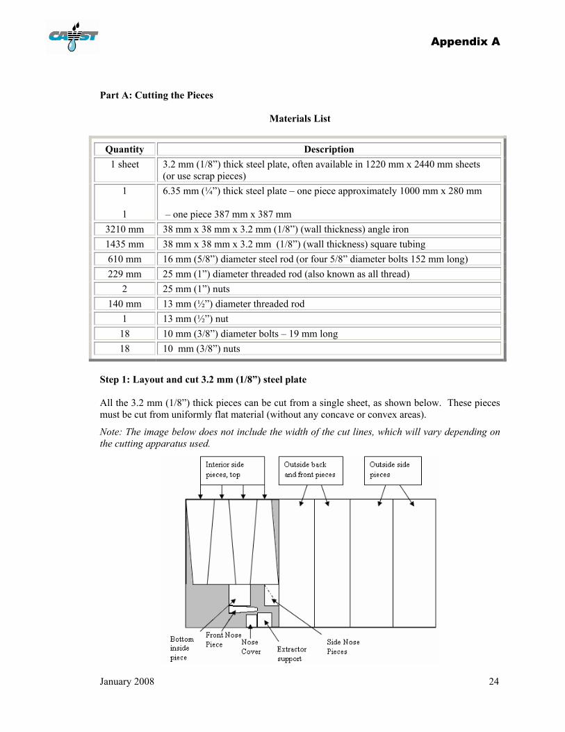
Part A: Cutting the Pieces
Materials List
Quantity Description 1 sheet 3.2 mm (1/8”) thick steel plate, often available in 1220 mm x 2440 mm sheets
(or use scrap pieces) 1
1
6.35 mm (¼”) thick steel plate – one piece approximately 1000 mm x 280 mm – one piece 387 mm x 387 mm
3210 mm 38 mm x 38 mm x 3.2 mm (1/8”) (wall thickness) angle iron 1435 mm 38 mm x 38 mm x 3.2 mm (1/8”) (wall thickness) square tubing 610 mm 16 mm (5/8”) diameter steel rod (or four 5/8” diameter bolts 152 mm long) 229 mm 25 mm (1”) diameter threaded rod (also known as all thread)
2 25 mm (1”) nuts 140 mm 13 mm (½”) diameter threaded rod
1 13 mm (½”) nut 18 10 mm (3/8”) diameter bolts – 19 mm long 18 10 mm (3/8”) nuts
Step 1: Layout and cut 3.2 mm (1/8”) steel plate All the 3.2 mm (1/8”) thick pieces can be cut from a single sheet, as shown below. These pieces must be cut from uniformly flat material (without any concave or convex areas).
Note: The image below does not include the width of the cut lines, which will vary depending on the cutting apparatus used.

Appendix A
January 2008 25
Step 1: Layout and cut 3.2 mm (1/8”) steel plate – continued Interior side pieces, top (4 pieces) OR, cut these plates from one sheet as shown,
but account for the width of the cuts
216
236
610
10
216
216
Bottom Inside Plate (1 Piece) Extractor support (1 Piece)
236
236
216
216
10
10
236
236
216
216
610
152
152
Drill a 29 mm diameter hole in the center of the plate

Appendix A
January 2008 26
Step 1: Layout and cut 3.2 mm (1/8”) steel plate – continued Exterior Back and Front panels (2 pieces) Exterior Side panels (2 pieces)
50 78 254
Side Nose Pieces (2 Pieces) Front Nose Piece (1 Piece)
229
111
Nose Cover Plate (1 Piece)
140
121
70
32 mm
Drill a 10 mm diameter hole
940
387
940
305
Hole for nose piece to be cut in front panel only - See below for dimensions

Appendix A
January 2008 27
Step 2: Layout and cut 6.4 mm ( ¼”) steel plate Interior side pieces, bottom (4 pieces) OR, cut these pieces from one plate as shown
below, but you must account for the width of the cuts
Base plate (1 piece) Note: It is symmetrical.
177
177
387 mm
Grey dashed line shows where interior mold will be welded on. Mark it on the base
33
32
267
267 387
242
252
264
5
252
252
242
242
5
5
252
252
242
242
264

Appendix A
January 2008 28
Step 3: Cut 38 x 38 (1 ½” x 1 ½”) angle iron pieces Total length of angle iron needed: 3213 mm Two 940 mm long pieces Two 387 mm long pieces
Two 305 mm long pieces
Step 4: Drill holes on angle iron Note: Our recommended hole locations are shown below; however, the specific positions of the holes are not critical. The most important thing is to ensure that the holes on one piece of the mold match up with the holes on another piece of the mold after it’s welded. If you drill the holes on every piece separately, they won’t line up exactly and it will be difficult to insert the bolts each time you assemble the mold.
Depending on the available tools, there are three different options:
• Drill pilot holes (less than 11 mm) on every piece (angle irons and plates) as you go, but wait to finish drilling the holes to 11 mm until the mold is assembled
• Mark the holes now, but wait to drill all the holes until the mold is clamped together at a later stage (must be done with a handheld tool, not a drill press)
• Drill the holes on the angle iron now but wait to drill the corresponding holes on the plates until the mold has been assembled (the method described in this booklet)
940
305 387
38
38
3.2

Appendix A
January 2008 29
Step 4 - continued Two 940 mm long pieces of angle iron, with five 11 mm diameter holes Two 387 mm long pieces of angle iron, with two 11 mm diameter holes Two 305 mm long pieces of angle iron, with two 11 mm diameter holes
19
387
117 117 11 mm diameter holes
76 76
305
19
11 mm diameter holes
19
229 229 222 19 19 222
940 mm 11 mm diameter holes

Appendix A
January 2008 30
Step 5: Cut 38 x 38 (1 ½” x 1 ½”) square tubing pieces Total square tubing needed: 1435 mm One (1) 387 mm long piece Two (2) 175 mm long pieces
Five (5) 89 mm long pieces Four (4) 57 mm long pieces
Step 6: Mark and drill holes in square tubing One (1) 387 mm long piece of square tubing, with 29 mm holes through two opposite sides
387 mm
19
194
29 mm diameter hole
387
38
38 3.2
175
89 57
Note: These holes do not
need to match up with other
parts of the mold (as in Step 4),
and can be drilled now.

Appendix A
January 2008 31
Step 6: Mark and drill holes in square tubing – continued One (1) 89 mm long piece of square tubing, with two (2) - 13 mm holes through two opposite sides Step 7: Cut 16 mm (5/8”) diameter steel rods Cut four (4) 152 mm rods as shown below: Part B: Welding Step 8: Interior mold box 1. Stand the 4 ‘top interior side pieces’ with the narrow ends up.
89
19
44
Fit the plates corner to corner with no gap.
Use the bottom inside plate to ensure that the 4 top interior side pieces are square.
16 mm
152 mm

Appendix A
January 2008 32
1
2
3
4
Step 8: Interior mold box - continued 2. Tack weld the top interior side plates together.
3. Check that the box is still square. If not, fix it.
4. Tack all 4 sides of the bottom inside plate to the top interior side plates.
5. Weld the complete lengths joining the 4 top interior side plates, in the order shown:
6. Check that the box is still square. If not, fix it.
7. Weld the edges of the top plate to the edges of the four side plates all the way around.
8. Stand the 4 ‘bottom interior side pieces’ with the narrow ends up.
9. Tack the bottom interior side plates together.
10. Check that the box is still square. If not, fix it.
Fit plates corner to corner with no gap
Weld on outside, same as was done as for the top interior side pieces
Note: The following is the most important part of welding the mold. This part of the interior mold box must be square so that the thickness of all the concrete filter walls will be consistent. Take the time to make sure that these pieces are welded together squarely and attached squarely to the rest of the interior mold.
Appendix A
January 2008 33
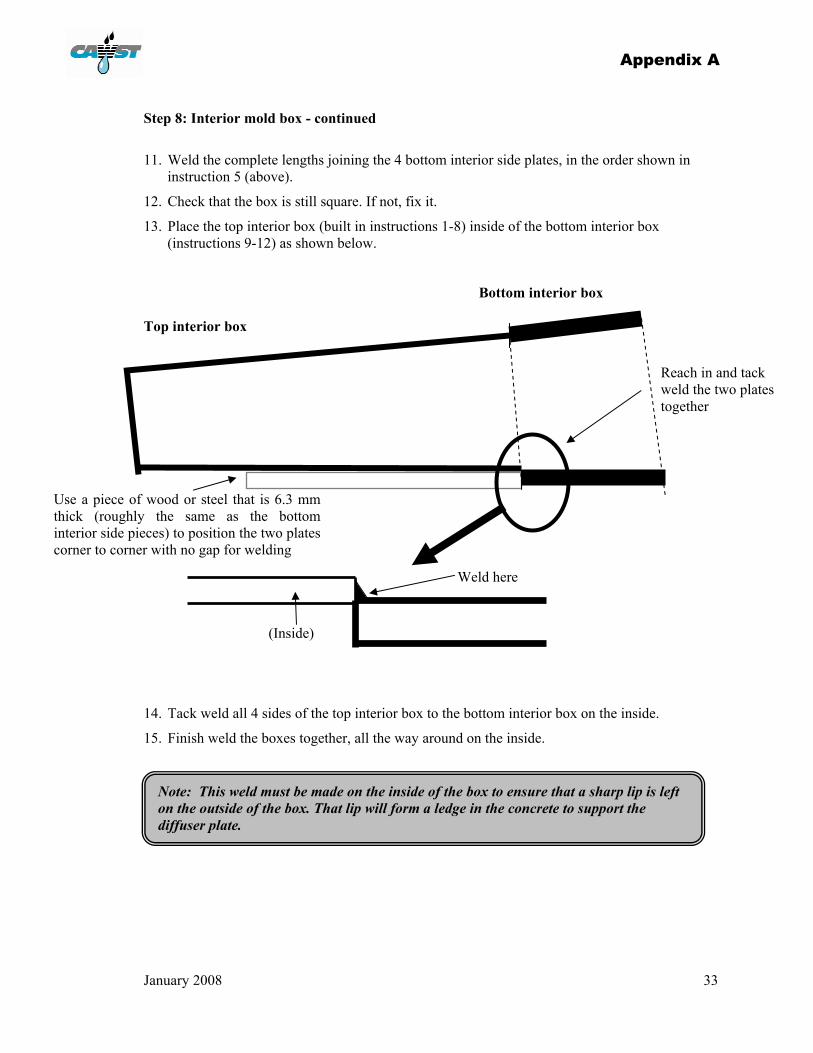
Step 8: Interior mold box - continued
11. Weld the complete lengths joining the 4 bottom interior side plates, in the order shown in instruction 5 (above).
12. Check that the box is still square. If not, fix it.
13. Place the top interior box (built in instructions 1-8) inside of the bottom interior box (instructions 9-12) as shown below.
Bottom interior box Top interior box 14. Tack weld all 4 sides of the top interior box to the bottom interior box on the inside.
15. Finish weld the boxes together, all the way around on the inside.
Use a piece of wood or steel that is 6.3 mm thick (roughly the same as the bottom interior side pieces) to position the two plates corner to corner with no gap for welding
(Inside)
Weld here
Reach in and tack weld the two plates together
Note: This weld must be made on the inside of the box to ensure that a sharp lip is left on the outside of the box. That lip will form a ledge in the concrete to support the diffuser plate.

Appendix A
January 2008 34
Step 9: Interior mold base Weld four pieces of 89 mm square tubing and one 25 mm NC Nut onto the base plate, as shown below. (Leave the 89 mm square tubing with a hole through it for Step 10.) Do not drill the holes in the plate at this time. They are drilled once the exterior box has been constructed. See Step 12.
Weld the 25 mm NC Nut to center of plate
Weld four 89 mm pieces of square tubing, one on each corner of the plate
Weld the nut and tubing on the opposite side from the grey dashed line that you marked in Step 2

Appendix A
January 2008 35
Step 10: Exterior mold - front panel Take one of the two 305 mm angle irons. Leave the other 305 mm angle iron for Step 11. Cut 38 mm off each end of the angle iron, but only on the side that has no holes, as shown below. Weld a 57 mm square tubing onto the centre of the angle iron. Weld the 13 mm nut over one of the holes on the remaining 89 mm long piece of square tubing. This nut is for the bolt that will hold the nose cover in place.
127 50 127
44
225
127 89 89
305 mm
Weld the 305 angle iron that you cut (above) to the front panel as shown
Cut a hole in one of the 305 mm x 940 mm exterior panels as shown below:
Then, weld angle iron onto 3 sides of the panel as shown below.
38
Weld a 940 long angle iron onto each side of the plate as shown.
305
229
Note: The joints between the
nose pieces and the front panel
do not form right angles.

Appendix A
January 2008 36
Step 10: Exterior mold - front panel - continued Step 11: Exterior mold – back and side panels Weld a 57 mm piece of square tubing onto the center of one of the 387 mm angle irons. Weld that angle iron to one of the 387 x 940 mm exterior side panels as shown below.
Weld the 89 square tubing to the front panel, centered horizontally, 63 mm from the bottom of the nose opening. The 13 mm nut should be facing the nose.
Weld the side nose pieces to the front nose piece and the front panel, from the inside.
Weld the front nose piece to both side nose pieces (254 mm sides), and to the front panel (50 mm end). All welding should be done from the inside.
63
Repeat the entire process for the other 387 mm angle iron and the other 387 x 940 mm exterior side panel.
387
Weld angle iron across the 387 mm end of the panel

Appendix A
January 2008 37
Step 11: Exterior mold – back and side panels – continued Weld a 57 mm piece of square tubing onto the center of the remaining 305 mm angle iron. Stand the exterior back and side panels as shown below. Place the exterior back panel 38 mm from the edge of the exterior side panels. Make sure the panels are square – at 90° angles to each other.
Weld angle iron across the 305 end of the panel
305
Weld that angle iron to the remaining 305 x 940 mm exterior panel as shown below.

Appendix A
January 2008 38
Step 11: Exterior mold – back and side panels – continued Step 12: Mold Completion Place the exterior mold panels on top of the base plate as shown below. Clamp all the components together so that they will not move. Complete the drilling of the bolt holes – wherever there is a hole in the angle iron, drill through the corresponding plate.
Tack weld the panels together and then check for squareness. Once they are square, stitch weld the panels together from the outside.
Note: It is not necessary to weld the entire length of the joints.
A stitch weld which runs the
length of the joint and has 25 mm welds spaced 150 mm apart
(centre-to-centre) is sufficient.
38
Appendix A
January 2008 39
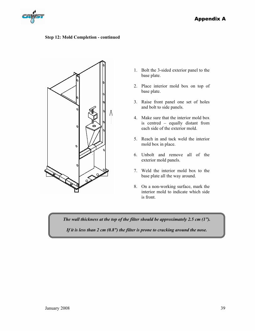
Step 12: Mold Completion - continued
1. Bolt the 3-sided exterior panel to the base plate.
2. Place interior mold box on top of
base plate. 3. Raise front panel one set of holes
and bolt to side panels. 4. Make sure that the interior mold box
is centred – equally distant from each side of the exterior mold.
5. Reach in and tack weld the interior
mold box in place. 6. Unbolt and remove all of the
exterior mold panels. 7. Weld the interior mold box to the
base plate all the way around. 8. On a non-working surface, mark the
interior mold to indicate which side is front.
The wall thickness at the top of the filter should be approximately 2.5 cm (1”).
If it is less than 2 cm (0.8”) the filter is prone to cracking around the nose.
Appendix A
January 2008 40
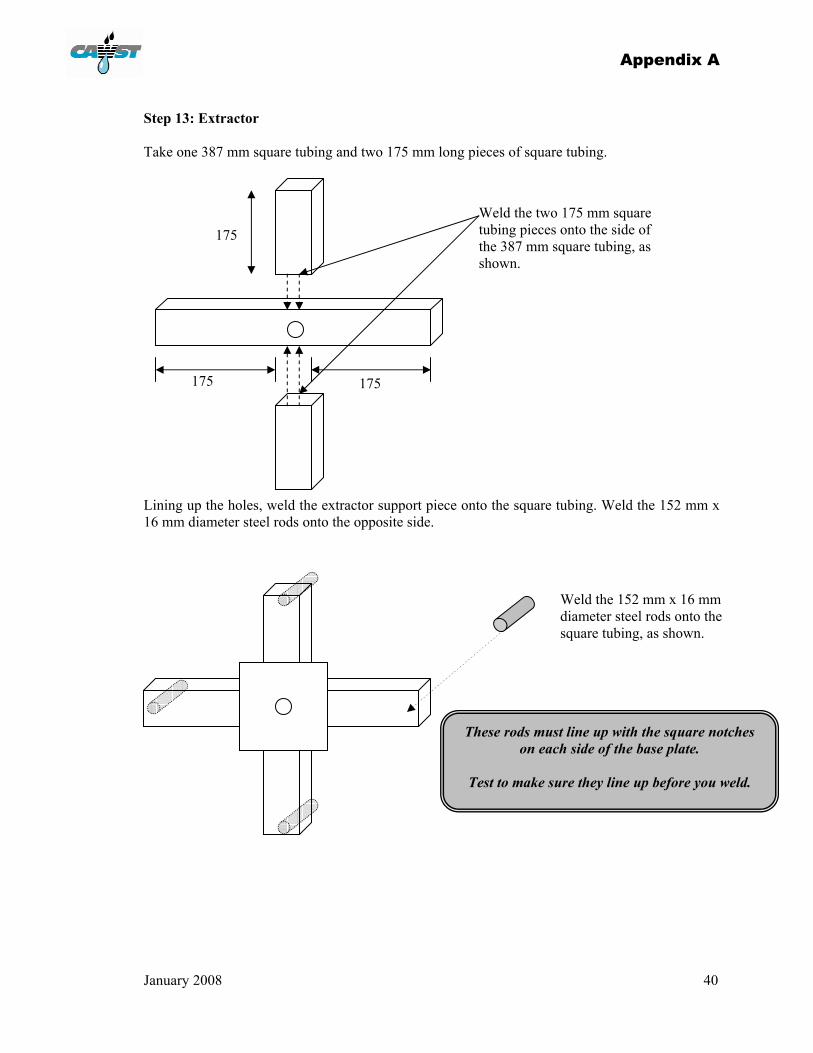
Step 13: Extractor Take one 387 mm square tubing and two 175 mm long pieces of square tubing. Lining up the holes, weld the extractor support piece onto the square tubing. Weld the 152 mm x 16 mm diameter steel rods onto the opposite side.
175 Weld the two 175 mm square tubing pieces onto the side of the 387 mm square tubing, as shown.
175 175
Weld the 152 mm x 16 mm diameter steel rods onto the square tubing, as shown.
These rods must line up with the square notches on each side of the base plate.
Test to make sure they line up before you weld.
Appendix A
January 2008 41
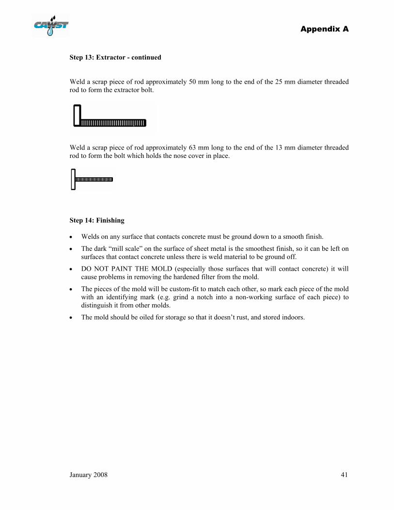
Step 13: Extractor - continued Weld a scrap piece of rod approximately 50 mm long to the end of the 25 mm diameter threaded rod to form the extractor bolt.
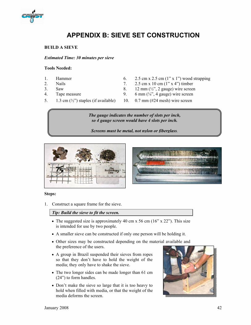
Weld a scrap piece of rod approximately 63 mm long to the end of the 13 mm diameter threaded rod to form the bolt which holds the nose cover in place.
Step 14: Finishing • Welds on any surface that contacts concrete must be ground down to a smooth finish.
• The dark “mill scale” on the surface of sheet metal is the smoothest finish, so it can be left on surfaces that contact concrete unless there is weld material to be ground off.
• DO NOT PAINT THE MOLD (especially those surfaces that will contact concrete) it will cause problems in removing the hardened filter from the mold.
• The pieces of the mold will be custom-fit to match each other, so mark each piece of the mold with an identifying mark (e.g. grind a notch into a non-working surface of each piece) to distinguish it from other molds.
• The mold should be oiled for storage so that it doesn’t rust, and stored indoors.
January 2008 42
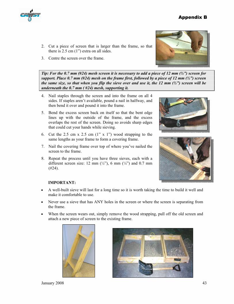
APPENDIX B: SIEVE SET CONSTRUCTION BUILD A SIEVE Estimated Time: 30 minutes per sieve Tools Needed: 1. Hammer 6. 2.5 cm x 2.5 cm (1” x 1”) wood strapping 2. Nails 7. 2.5 cm x 10 cm (1” x 4”) timber 3. Saw 8. 12 mm (½”, 2 gauge) wire screen 4. Tape measure 9. 6 mm (¼”, 4 gauge) wire screen 5. 1.3 cm (½”) staples (if available) 10. 0.7 mm (#24 mesh) wire screen
Steps: 1. Construct a square frame for the sieve.
Tip: Build the sieve to fit the screen.
• The suggested size is approximately 40 cm x 56 cm (16” x 22”). This size is intended for use by two people.
• A smaller sieve can be constructed if only one person will be holding it.
• Other sizes may be constructed depending on the material available and the preference of the users.
• A group in Brazil suspended their sieves from ropes so that they don’t have to hold the weight of the media; they only have to shake the sieve.
• The two longer sides can be made longer than 61 cm (24”) to form handles.
• Don’t make the sieve so large that it is too heavy to hold when filled with media, or that the weight of the media deforms the screen.
The gauge indicates the number of slots per inch, so 4 gauge screen would have 4 slots per inch.
Screens must be metal, not nylon or fiberglass.
Appendix B
January 2008 43
2. Cut a piece of screen that is larger than the frame, so that there is 2.5 cm (1”) extra on all sides.
3. Centre the screen over the frame.
Tip: For the 0.7 mm (#24) mesh screen it is necessary to add a piece of 12 mm (½”) screen for support. Place 0.7 mm (#24) mesh on the frame first, followed by a piece of 12 mm (½”) screen the same size, so that when you flip the sieve over and use it, the 12 mm (½”) screen will be underneath the 0.7 mm ( #24) mesh, supporting it.
4. Nail staples through the screen and into the frame on all 4 sides. If staples aren’t available, pound a nail in halfway, and then bend it over and pound it into the frame.
5. Bend the excess screen back on itself so that the bent edge lines up with the outside of the frame, and the excess overlaps the rest of the screen. Doing so avoids sharp edges that could cut your hands while sieving.
6. Cut the 2.5 cm x 2.5 cm (1” x 1”) wood strapping to the same lengths as your frame to form a covering frame.
7. Nail the covering frame over top of where you’ve nailed the screen to the frame.
8. Repeat the process until you have three sieves, each with a different screen size: 12 mm (½”), 6 mm (¼”) and 0.7 mm (#24).
IMPORTANT:
• A well-built sieve will last for a long time so it is worth taking the time to build it well and make it comfortable to use.
• Never use a sieve that has ANY holes in the screen or where the screen is separating from the frame.
• When the screen wears out, simply remove the wood strapping, pull off the old screen and attach a new piece of screen to the existing frame.

January 2008 44
APPENDIX C: MEDIA PREPARATION The selection and preparation of the sand and gravel is important to the effectiveness and efficiency of the biosand filter. While not complicated, the steps in preparing the media must be followed exactly as presented. Poor selection and preparation of the media could lead to poor performance and a considerable amount of rework to rectify the problem. Locating a source of media:
Source Reason
• Crushed rock is the best type of media. Gravel pits or quarries are the best place to obtain sand, and are common in most parts of the world.
• This sand has less uniform sizing of the grains. A mixture of grain sizes is required for the proper functioning of the filter.
• Freshly crushed rock has less chance of becoming contaminated with pathogens or organic material.
• If crushed rock is absolutely not available, the next choice is sand from high on the banks of a river (that has not been in the water), and the last choice would be sand in the riverbed itself.
• River sand is often contaminated with bacteria and organic material.
• Beach sand should not be used.
• Beach sand usually contains salt, organic material and other contaminants that will dissolve into the filtered water. It is very difficult to remove this from the beach sand.
Properties to look for when selecting the media:
Should: Should NOT:
• When you pick up a handful of the sand, you should be able to feel the coarseness of the grains.
• You should be able to clearly see the individual grains, and the grains should be of different sizes and shapes.
• When you squeeze a handful of dry sand, and then you open your hand, the sand should all pour smoothly out of your hand.
• Sand and any gravel up to 12 mm (½”) in diameter should be used. Using gravel larger than 12 mm (½”) will result in a lot of waste.
• It should not contain any organic material (e.g. leaves, grass, sticks, loam, dirt).
• It should not contain possible microbiological contamination. Avoid areas that have been used frequently by people or animals.
• It should not be very fine sand or sand that is mostly silt and clay.
• When you squeeze a handful of dry sand, it should not ball up in your hand or stick to your hand. If it does, it probably contains a lot of dirt or clay.
Appendix C
January 2008 45
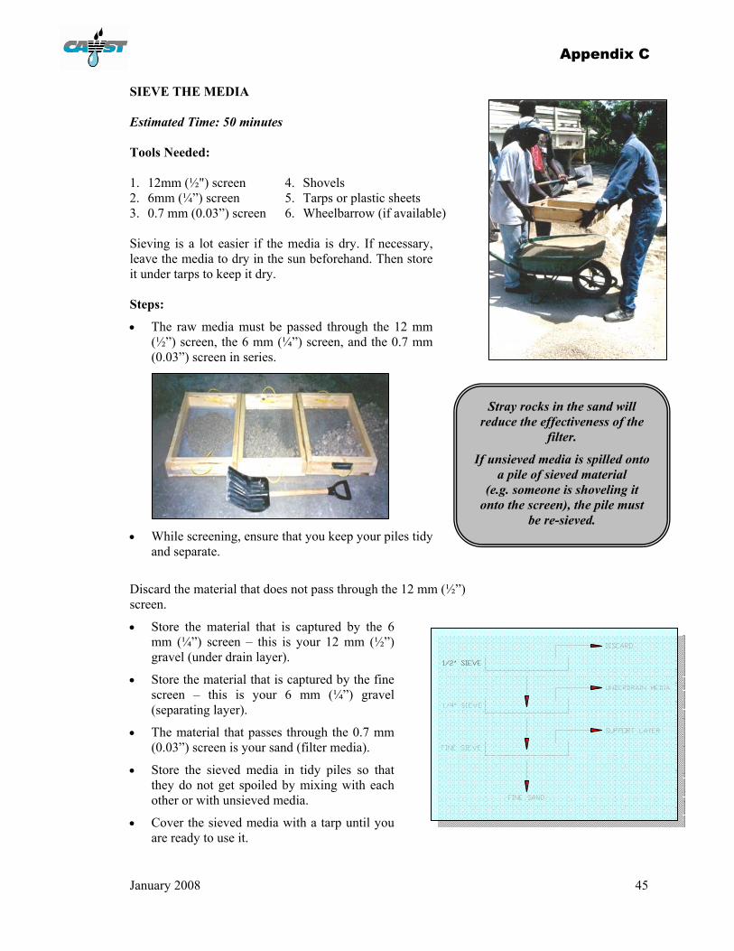
SIEVE THE MEDIA Estimated Time: 50 minutes Tools Needed: 1. 12mm (½") screen 4. Shovels 2. 6mm (¼”) screen 5. Tarps or plastic sheets 3. 0.7 mm (0.03”) screen 6. Wheelbarrow (if available) Sieving is a lot easier if the media is dry. If necessary, leave the media to dry in the sun beforehand. Then store it under tarps to keep it dry. Steps:
• The raw media must be passed through the 12 mm (½”) screen, the 6 mm (¼”) screen, and the 0.7 mm (0.03”) screen in series.
• While screening, ensure that you keep your piles tidy and separate.
Discard the material that does not pass through the 12 mm (½”) screen.
• Store the material that is captured by the 6 mm (¼”) screen – this is your 12 mm (½”) gravel (under drain layer).
• Store the material that is captured by the fine screen – this is your 6 mm (¼”) gravel (separating layer).
• The material that passes through the 0.7 mm (0.03”) screen is your sand (filter media).
• Store the sieved media in tidy piles so that they do not get spoiled by mixing with each other or with unsieved media.
• Cover the sieved media with a tarp until you are ready to use it.
Stray rocks in the sand will reduce the effectiveness of the
filter.
If unsieved media is spilled onto a pile of sieved material
(e.g. someone is shoveling it onto the screen), the pile must
be re-sieved.
Appendix C
January 2008 46
WASH THE MEDIA
Estimated Time: 50 minutes Tools Needed:
1. Buckets 2. Clean water (not biologically contaminated, if possible) 3. 2 glass jars
Steps:
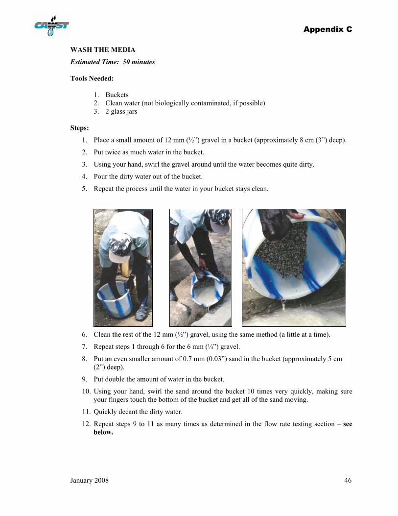
1. Place a small amount of 12 mm (½”) gravel in a bucket (approximately 8 cm (3”) deep).
2. Put twice as much water in the bucket.
3. Using your hand, swirl the gravel around until the water becomes quite dirty.
4. Pour the dirty water out of the bucket.
5. Repeat the process until the water in your bucket stays clean.
6. Clean the rest of the 12 mm (½”) gravel, using the same method (a little at a time).
7. Repeat steps 1 through 6 for the 6 mm (¼”) gravel.
8. Put an even smaller amount of 0.7 mm (0.03”) sand in the bucket (approximately 5 cm (2”) deep).
9. Put double the amount of water in the bucket.
10. Using your hand, swirl the sand around the bucket 10 times very quickly, making sure your fingers touch the bottom of the bucket and get all of the sand moving.
11. Quickly decant the dirty water.
12. Repeat steps 9 to 11 as many times as determined in the flow rate testing section – see below.
Appendix C
January 2008 47
Tip: Do not wash the sand until the water in your bucket runs clean. This residual water should still be somewhat dirty. It takes time and practice to be able to know how much to wash the sand.
13. Clean the rest of the sand using the same method (steps 8 through 12).
14. Place all of the media on a tarp or concrete surface in the sun to dry. This step is especially important if the media or the wash water might be biologically contaminated.
15. Store the media under tarps once it is dry.
FLOW RATE - TEST THE SAND
• Wash the sand as described in steps 8 to 11 above.
• As you wash, count the number of times that you decant your bucket.
• The first time you wash the sand, it is necessary to experiment with the washing procedure in order to determine the proper number of washes.
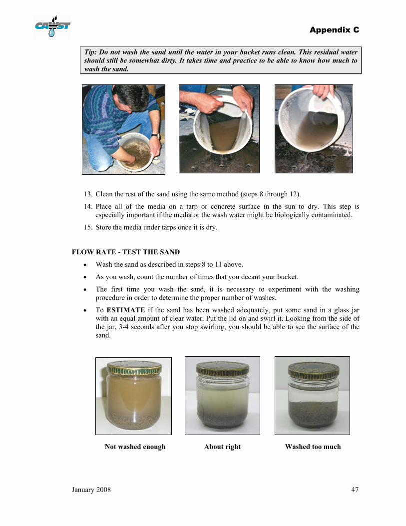
• To ESTIMATE if the sand has been washed adequately, put some sand in a glass jar with an equal amount of clear water. Put the lid on and swirl it. Looking from the side of the jar, 3-4 seconds after you stop swirling, you should be able to see the surface of the sand.
Not washed enough About right Washed too much

Appendix C
January 2008 48
• For the final test of the sand, install a biosand filter on site using your media, and test the flow rate. It should be 0.6 L/minute or less.
• If the flow rate is greater than 0.6 L/minute, the sand has been washed too much. You must decrease the number of times that you wash the sand. A flow rate that is too fast is not acceptable – the filter will not be effective.
• If the flow rate is less than 0.6 L/minute, the sand hasn’t been washed enough. You must increase the number of times that you wash the sand. The filter will still function if the flow rate is too slow, but it may clog more often, requiring more frequent maintenance. If the flow rate is just slightly less than 0.6 L/minute, it can be left as is – as long as the flow rate isn’t so slow that it is inconvenient for the user.
• Initially, it is a trial and error process – but that is why its important to count how many times you wash the sand, so that once you get the correct flow rate, you can repeat the same process.
• The media will vary so the number of times that you wash the sand will have to be adjusted periodically, but after some time you should develop the ability to know when the sand has been adequately washed, just by looking at the wash water in your bucket.
January 2008 49
APPENDIX D: CONCRETE FILTER CONSTRUCTION Option A – Plastic Tubing MAKE PLASTIC OUTLET PIPE Estimated Time: 10 minutes Tools Needed: 1. 6 mm (¼”) I.D. plastic tubing –
polyethylene or vinyl (clear plastic tubing) 3. Heat source – propane or kerosene torch, wood fire, electric burner
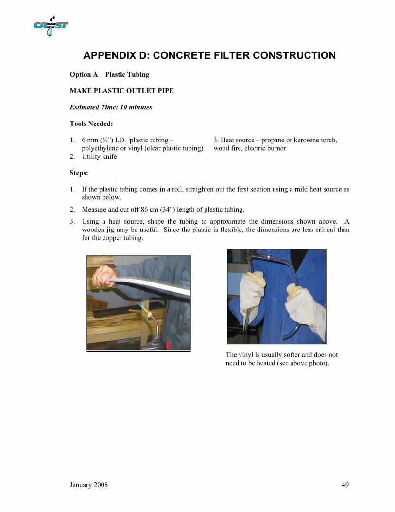
2. Utility knife Steps: 1. If the plastic tubing comes in a roll, straighten out the first section using a mild heat source as
shown below.
2. Measure and cut off 86 cm (34”) length of plastic tubing.
3. Using a heat source, shape the tubing to approximate the dimensions shown above. A wooden jig may be useful. Since the plastic is flexible, the dimensions are less critical than for the copper tubing.
The vinyl is usually softer and does not need to be heated (see above photo).
Appendix D
January 2008 50
Option B – Copper Tubing MAKE COPPER OUTLET PIPE
Estimated Time: 10 minutes
Tools Needed: 1. 6 mm (¼”) I.D. copper pipe 3. 1 roller pipe cutter or 1 hack saw 2. 1 tube bending tool
Steps:
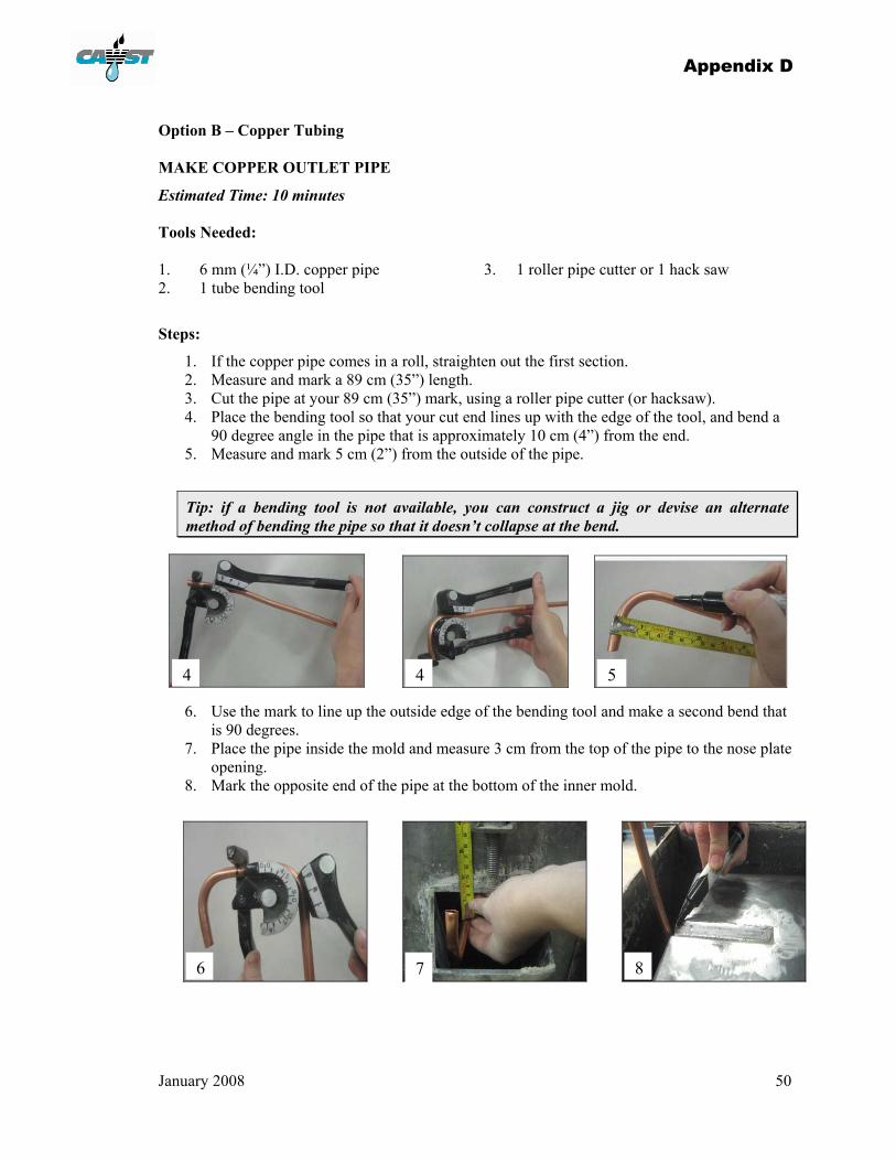
1. If the copper pipe comes in a roll, straighten out the first section. 2. Measure and mark a 89 cm (35”) length. 3. Cut the pipe at your 89 cm (35”) mark, using a roller pipe cutter (or hacksaw). 4. Place the bending tool so that your cut end lines up with the edge of the tool, and bend a
90 degree angle in the pipe that is approximately 10 cm (4”) from the end. 5. Measure and mark 5 cm (2”) from the outside of the pipe.
Tip: if a bending tool is not available, you can construct a jig or devise an alternate method of bending the pipe so that it doesn’t collapse at the bend.
6. Use the mark to line up the outside edge of the bending tool and make a second bend that is 90 degrees.
7. Place the pipe inside the mold and measure 3 cm from the top of the pipe to the nose plate opening.
8. Mark the opposite end of the pipe at the bottom of the inner mold.
4 4 5
6 7 8
Appendix D
January 2008 51
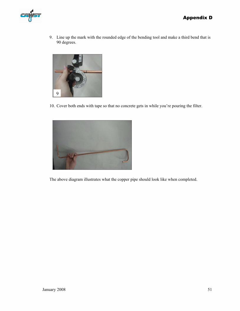
9. Line up the mark with the rounded edge of the bending tool and make a third bend that is 90 degrees.
10. Cover both ends with tape so that no concrete gets in while you’re pouring the filter.
The above diagram illustrates what the copper pipe should look like when completed.
9
Appendix D
January 2008 52
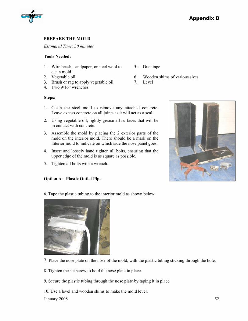
PREPARE THE MOLD
Estimated Time: 30 minutes Tools Needed: 1. Wire brush, sandpaper, or steel wool to
clean mold 5. Duct tape
2. Vegetable oil 6. Wooden shims of various sizes 3. Brush or rag to apply vegetable oil 7. Level 4. Two 9/16” wrenches
Steps: 1. Clean the steel mold to remove any attached concrete.
Leave excess concrete on all joints as it will act as a seal.
2. Using vegetable oil, lightly grease all surfaces that will be in contact with concrete.
3. Assemble the mold by placing the 2 exterior parts of the mold on the interior mold. There should be a mark on the interior mold to indicate on which side the nose panel goes.
4. Insert and loosely hand tighten all bolts, ensuring that the upper edge of the mold is as square as possible.
5. Tighten all bolts with a wrench.
Option A – Plastic Outlet Pipe
6. Tape the plastic tubing to the interior mold as shown below.
7. Place the nose plate on the nose of the mold, with the plastic tubing sticking through the hole. 8. Tighten the set screw to hold the nose plate in place. 9. Secure the plastic tubing through the nose plate by taping it in place. 10. Use a level and wooden shims to make the mold level.
Appendix D
January 2008 53
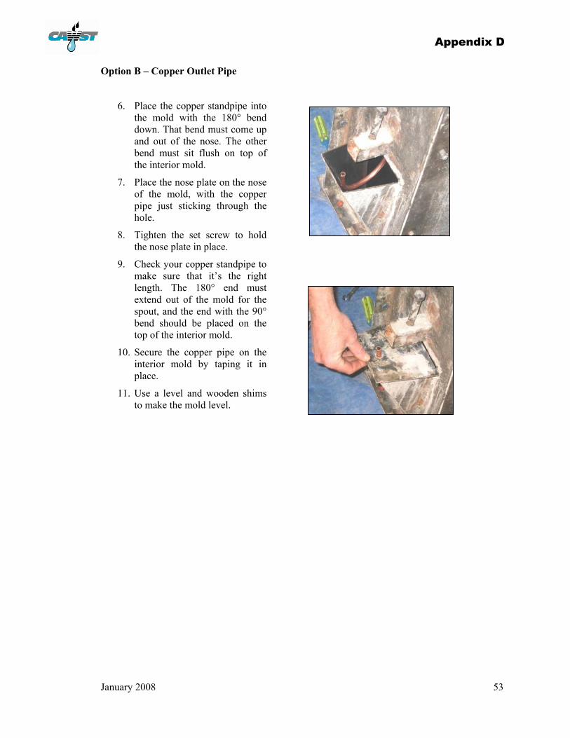
Option B – Copper Outlet Pipe
6. Place the copper standpipe into the mold with the 180° bend down. That bend must come up and out of the nose. The other bend must sit flush on top of the interior mold.
7. Place the nose plate on the nose of the mold, with the copper pipe just sticking through the hole.
8. Tighten the set screw to hold the nose plate in place.
9. Check your copper standpipe to make sure that it’s the right length. The 180° end must extend out of the mold for the spout, and the end with the 90° bend should be placed on the top of the interior mold.
10. Secure the copper pipe on the interior mold by taping it in place.
11. Use a level and wooden shims to make the mold level.

Appendix D
January 2008 54
POUR THE FILTER
Estimated Time: First attempt – 1 ½ hours, with practice – 30 minutes Tools Needed: 1. Shovels 4. 1.5 m (5’) metal rod (such as rebar) or
piece of wood 2. Wooden shims of various sizes 5. Mallet 3. Buckets for measuring sand, gravel and
cement 6. Trowel
Steps: 1. Measure 12 litres of Portland cement, 24 litres of sieved 0.7 mm (0.03”) sand, 12 litres of
sieved 12 mm (½”) gravel, and 12 litres of sieved 6 mm (¼”) gravel.
2. Mix dry ingredients together thoroughly.
3. Add water gradually while mixing to make a fairly stiff mix (cookie-dough consistency). Approximately 7 litres of water is needed, depending on the dampness of the sand and gravel.
4. Place concrete into the mold, a few shovel fulls or half a pail at a time.
This mixture will set in about 24 hours and allows one filter to be built a day from each mold. If less cement is used, the setting time may increase. Different cements will also
change the set time.
Appendix D
January 2008 55
5. As each layer of cement is added to the mold, use the rebar as a tamper to ensure the concrete completely fills the area without any voids. At the current level of the concrete, hit the outside of the mold on all sides, including the nose, with the mallet in an upward pattern. (The vibration allows air pockets to escape the concrete.)
6. As you fill the last of the mold, check the nose plate and standpipe to be sure that the pipe or plastic tubing has not moved.
7. Fill around the tubing while hitting the outside with the mallet to ensure that the concrete has completely filled the space.
8. Jab your trowel at least 10 cm (4”) into the concrete, all around the inner mold, to ensure that the final layer mixes with the previous layer. This will also allow for the concrete to settle down the sides more.
9. Pile a shovel full of concrete on the top and allow it to settle for 30 minutes.
10. Repeat step 9. Smooth away the excess concrete and then use a trowel to make a flat surface . This will be the bottom of the filter.
11. Do not leave the filter in the mold for longer than 24 hours.

Appendix D
January 2008 56
REMOVE FILTER FROM MOLD
Estimated Time: 45 minutes Tools Needed: 1. Two 9/16” wrenches 4. One hammer 2. One 1-1/2” wrench 5. Wooden spacers 3. One block of wood 6. Soap and scrub brush or broom
Steps:
Within 18 to 24 hours, remove the filter from the mold, as follows:
1. Loosen the set screw and remove the nose plate.
2. Turn the mold completely upside down (180°), using a tire or a sack of grain to support its weight as you go.
3. Remove the bolts on top of the mold. Do not loosen any of the side bolts yet.
4. Hit the top of the mold with a mallet (or use a block of wood and a hammer), to loosen the bond with the concrete.
5. Position the puller assembly on top of the mold. Each rod of the puller should sit in the corresponding slot on the inner mold.
6. Tighten the centre bolt (by turning the bolt clockwise) until the bolt is well threaded into the nut on the mold.
7. Tighten the nut (which sits above the square tubing) by turning it clockwise. Turn the nut down until it contacts the square tubing and then continue turning, which pulls upward on the interior mold until it releases.
8. Continue turning the central nut until the interior mold is entirely released.
If the mold starts to bend, stop what you’re doing immediately.
Undo all bolts, remove the exterior panels and
break the concrete off of the interior mold.
Do not damage the mold for just one filter.
Appendix D
January 2008 57
9. Place wooden spacers between the exterior mold and the interior mold.
10. Loosen the nut on the puller assembly until the interior mold rests on the wooden spacers.
11. Remove the puller assembly.
12. Carefully remove the interior mold and place it in a safe location.
13. Remove the remaining bolts and the 3-sided panel.
14. Remove the front (nose) panel.
Tip: You may need to tip the filter back and place a wooden shim under the front edge, and then use a hammer and small pry bars to detach the front panel.
15. Clean and oil the mold.
16. Remove the tape that covers the standpipe opening in the interior of the filter. Remove the tape on the other end.
17. Check the two ends of the outlet pipe to ensure they are not plugged by concrete. Remove any visible debris until you can clearly see or feel the outlet at the bottom of the filter.
18. Fill the filter with water. The flow rate should be approximately 2.5 L/ minute.
19. Determine water level within the filter once the water stops coming out of the spout.
20. If the water level is above the diffuser lip, cut the outlet pipe to be 1.5–2.5 cm (½–1”) in length. Repeat steps 18 and 19 until water level is below the diffuser lip.
21. Check for cracks and flaws in the filter.
22. Plug the outlet and completely fill the filter with water. Keep it full for five to seven days while the concrete cures. Do not transport the filter any significant distance during that time.
23. Filters with water may lead to a breeding ground for insect vectors. To prevent a breeding ground for insect vectors, ensure filters are covered, emptied, or tipped over.
24. Put a small amount of soap in the water that was sitting in the filter, and scrub the inside of the filter out with a broom or scrub brush.
The water level in the filter is determined by the outlet pipe. Due to a siphoning effect, the water will stop coming out of the filter when the water is at
the same level as the end of the outlet pipe.

January 2008 58
APPENDIX E : DIFFUSER AND LID DIFFUSER PLATE The purpose of the diffuser plate is to prevent any disturbance of the media surface and biolayer when water is added to the top of the filter. It is essential to the correct operation of the filter. There are several types of diffusers that can be built – each with its own advantages and limitations. The one that you choose to build will depend on your skill level, the tools and materials that are available, and the preference of the user.
Required features of all diffusers:
• 3 mm (1/8”) diameter holes in a 2.5 cm x 2.5 cm (1” x 1”) grid pattern.
• There should not be a gap between the edge of the diffuser and the concrete filter. A tight fit will also prevent the floating of lighter material.
• Many materials have been used for the diffusers – sheet metal, plastic, concrete, etc.
• Avoid using any material that will rot or cause the growth of mold or algae in the presence of water (e.g. wood).
• The least expensive material that is suitable should be used to keep the cost of filters at a minimum.
• The deep metal box diffuser is used for the arsenic removal adaptation of the biosand filter.
Larger holes will result in disturbance of the surface of the media. It is important that the biolayer is protected so that pathogens do not penetrate far into the sand bed.
Smaller holes will restrict the flow through the filter, possibly causing the flow rate to drop.
A gap allows water to travel along the walls of the filter, rather than being distributed evenly through the holes of the diffuser plate.
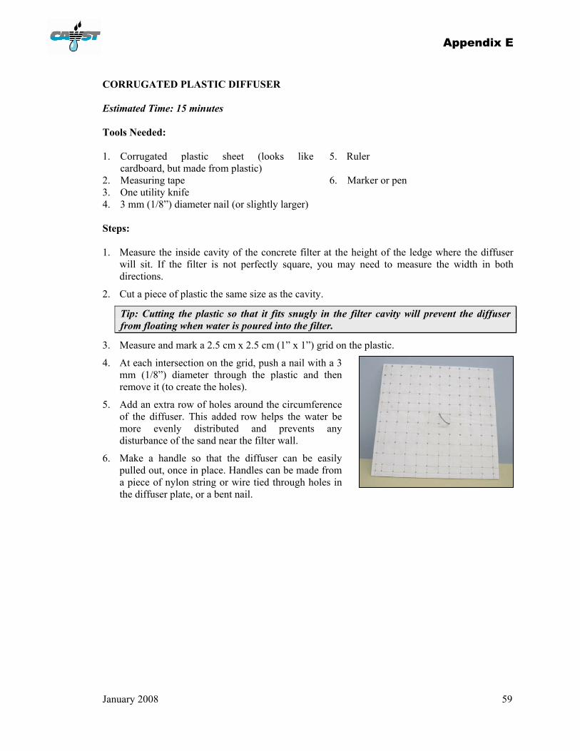
Appendix E
January 2008 59
CORRUGATED PLASTIC DIFFUSER Estimated Time: 15 minutes Tools Needed: 1. Corrugated plastic sheet (looks like
cardboard, but made from plastic) 5. Ruler
2. Measuring tape 6. Marker or pen 3. One utility knife 4. 3 mm (1/8”) diameter nail (or slightly larger)
Steps: 1. Measure the inside cavity of the concrete filter at the height of the ledge where the diffuser
will sit. If the filter is not perfectly square, you may need to measure the width in both directions.
2. Cut a piece of plastic the same size as the cavity.
Tip: Cutting the plastic so that it fits snugly in the filter cavity will prevent the diffuser from floating when water is poured into the filter.
3. Measure and mark a 2.5 cm x 2.5 cm (1” x 1”) grid on the plastic.
4. At each intersection on the grid, push a nail with a 3 mm (1/8”) diameter through the plastic and then remove it (to create the holes).
5. Add an extra row of holes around the circumference of the diffuser. This added row helps the water be more evenly distributed and prevents any disturbance of the sand near the filter wall.
6. Make a handle so that the diffuser can be easily pulled out, once in place. Handles can be made from a piece of nylon string or wire tied through holes in the diffuser plate, or a bent nail.
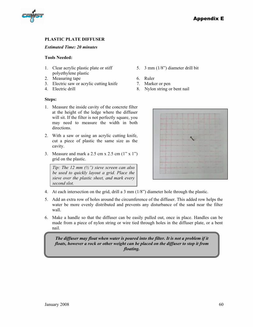
Appendix E
January 2008 60
PLASTIC PLATE DIFFUSER
Estimated Time: 20 minutes Tools Needed: 1. Clear acrylic plastic plate or stiff
polyethylene plastic 5. 3 mm (1/8”) diameter drill bit
2. Measuring tape 6. Ruler 3. Electric saw or acrylic cutting knife 7. Marker or pen 4. Electric drill 8. Nylon string or bent nail Steps:
1. Measure the inside cavity of the concrete filter at the height of the ledge where the diffuser will sit. If the filter is not perfectly square, you may need to measure the width in both directions.
2. With a saw or using an acrylic cutting knife, cut a piece of plastic the same size as the cavity.
3. Measure and mark a 2.5 cm x 2.5 cm (1” x 1”) grid on the plastic.
Tip: The 12 mm (½”) sieve screen can also be used to quickly layout a grid. Place the sieve over the plastic sheet, and mark every second slot.
4. At each intersection on the grid, drill a 3 mm (1/8”) diameter hole through the plastic.
5. Add an extra row of holes around the circumference of the diffuser. This added row helps the water be more evenly distributed and prevents any disturbance of the sand near the filter wall.
6. Make a handle so that the diffuser can be easily pulled out, once in place. Handles can be made from a piece of nylon string or wire tied through holes in the diffuser plate, or a bent nail.
The diffuser may float when water is poured into the filter. It is not a problem if it floats, however a rock or other weight can be placed on the diffuser to stop it from
floating.
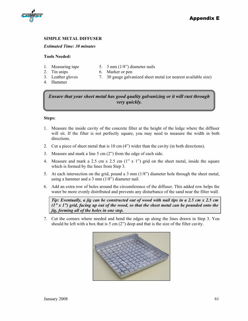
Appendix E
January 2008 61
SIMPLE METAL DIFFUSER
Estimated Time: 30 minutes Tools Needed: 1. Measuring tape 5. 3 mm (1/8”) diameter nails 2. Tin snips 6. Marker or pen 3. Leather gloves 7. 30 gauge galvanized sheet metal (or nearest available size) 4. Hammer Steps: 1. Measure the inside cavity of the concrete filter at the height of the ledge where the diffuser
will sit. If the filter is not perfectly square, you may need to measure the width in both directions.
2. Cut a piece of sheet metal that is 10 cm (4”) wider than the cavity (in both directions).
3. Measure and mark a line 5 cm (2”) from the edge of each side.
4. Measure and mark a 2.5 cm x 2.5 cm (1” x 1”) grid on the sheet metal, inside the square which is formed by the lines from Step 3.
5. At each intersection on the grid, pound a 3 mm (1/8”) diameter hole through the sheet metal, using a hammer and a 3 mm (1/8”) diameter nail.
6. Add an extra row of holes around the circumference of the diffuser. This added row helps the water be more evenly distributed and prevents any disturbance of the sand near the filter wall.
Tip: Eventually, a jig can be constructed out of wood with nail tips in a 2.5 cm x 2.5 cm (1” x 1”) grid, facing up out of the wood, so that the sheet metal can be pounded onto the jig, forming all of the holes in one step.
7. Cut the corners where needed and bend the edges up along the lines drawn in Step 3. You should be left with a box that is 5 cm (2”) deep and that is the size of the filter cavity.
Ensure that your sheet metal has good quality galvanizing or it will rust through very quickly.
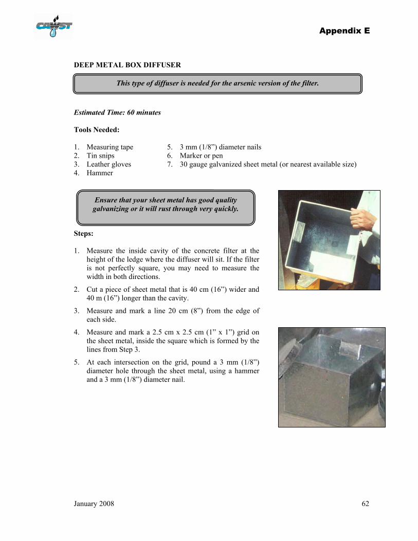
Appendix E
January 2008 62
DEEP METAL BOX DIFFUSER
Estimated Time: 60 minutes Tools Needed: 1. Measuring tape 5. 3 mm (1/8”) diameter nails 2. Tin snips 6. Marker or pen 3. Leather gloves 7. 30 gauge galvanized sheet metal (or nearest available size) 4. Hammer Steps: 1. Measure the inside cavity of the concrete filter at the
height of the ledge where the diffuser will sit. If the filter is not perfectly square, you may need to measure the width in both directions.
2. Cut a piece of sheet metal that is 40 cm (16”) wider and 40 m (16”) longer than the cavity.
3. Measure and mark a line 20 cm (8”) from the edge of each side.
4. Measure and mark a 2.5 cm x 2.5 cm (1” x 1”) grid on the sheet metal, inside the square which is formed by the lines from Step 3.
5. At each intersection on the grid, pound a 3 mm (1/8”) diameter hole through the sheet metal, using a hammer and a 3 mm (1/8”) diameter nail.
This type of diffuser is needed for the arsenic version of the filter.
Ensure that your sheet metal has good quality galvanizing or it will rust through very quickly.
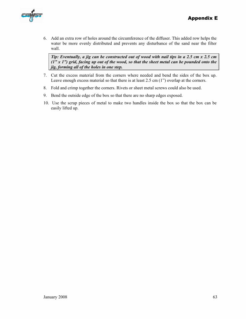
Appendix E
January 2008 63
6. Add an extra row of holes around the circumference of the diffuser. This added row helps the water be more evenly distributed and prevents any disturbance of the sand near the filter wall.
Tip: Eventually, a jig can be constructed out of wood with nail tips in a 2.5 cm x 2.5 cm (1” x 1”) grid, facing up out of the wood, so that the sheet metal can be pounded onto the jig, forming all of the holes in one step.
7. Cut the excess material from the corners where needed and bend the sides of the box up. Leave enough excess material so that there is at least 2.5 cm (1”) overlap at the corners.
8. Fold and crimp together the corners. Rivets or sheet metal screws could also be used.
9. Bend the outside edge of the box so that there are no sharp edges exposed.
10. Use the scrap pieces of metal to make two handles inside the box so that the box can be easily lifted up.
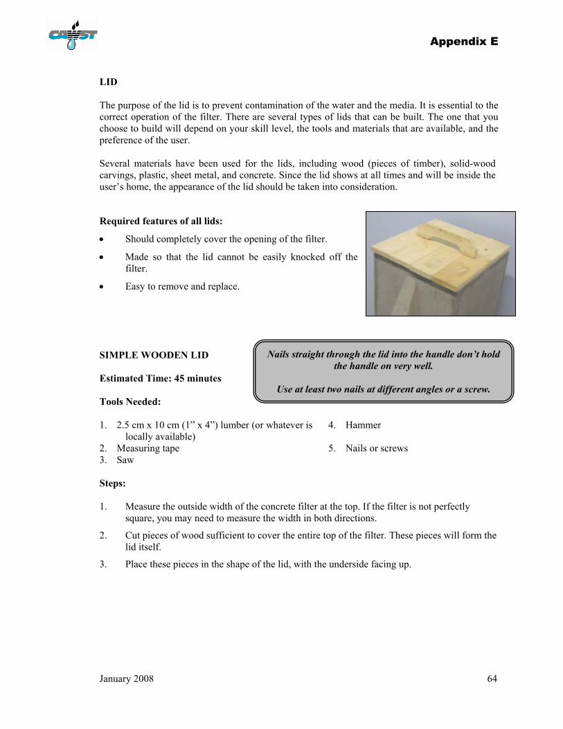
Appendix E
January 2008 64
LID The purpose of the lid is to prevent contamination of the water and the media. It is essential to the correct operation of the filter. There are several types of lids that can be built. The one that you choose to build will depend on your skill level, the tools and materials that are available, and the preference of the user. Several materials have been used for the lids, including wood (pieces of timber), solid-wood carvings, plastic, sheet metal, and concrete. Since the lid shows at all times and will be inside the user’s home, the appearance of the lid should be taken into consideration.
Required features of all lids:
• Should completely cover the opening of the filter.
• Made so that the lid cannot be easily knocked off the filter.
• Easy to remove and replace.
SIMPLE WOODEN LID Estimated Time: 45 minutes Tools Needed: 1. 2.5 cm x 10 cm (1” x 4”) lumber (or whatever is
locally available) 4. Hammer
2. Measuring tape 5. Nails or screws 3. Saw Steps: 1. Measure the outside width of the concrete filter at the top. If the filter is not perfectly
square, you may need to measure the width in both directions.
2. Cut pieces of wood sufficient to cover the entire top of the filter. These pieces will form the lid itself.
3. Place these pieces in the shape of the lid, with the underside facing up.
Nails straight through the lid into the handle don’t hold the handle on very well.
Use at least two nails at different angles or a screw.

Appendix E
January 2008 65
4. Measure the opening of the concrete filter at the very top (inside width). If the filter is not perfectly square, you may need to measure the width in both directions.
5. Mark the size and position of the opening on the pieces of your lid (from Step 3).
6. Cut two pieces of wood the length of the opening of the filter.
7. Place those two pieces of wood perpendicular to the other pieces, on top of the others.
8. Centre those two pieces of wood so that in both directions, they line up with the opening of the filter that you marked in Step 5. (Those two pieces will sit inside the opening on the filter and will stop the lid from moving in either direction.)
9. Nail each of the two pieces onto all of the other pieces.
10. Flip your lid over and ensure that it fits on the filter. (The two pieces from Step 6 should just fit inside the filter, and the other pieces should cover the entire top edge of the filter.)
11. Attach a handle.
.

January 2008 66
APPENDIX F: INSTALLATION, OPERATION, AND MAINTENEANCE For a biosand filter to operate properly, it must be installed and commissioned correctly. Make a checklist and use it to ensure that you have everything you’ll need before you head out to install a filter. A filter maintenance guide (such as a laminated sheet, sticker or pamphlet) should be left with each new user. TRANSPORTING THE FILTER
Always consider the safety issues related to moving the filter. There can be injuries due to strains of the back, arms, and knees. Watch out for crushing or pinching of fingers and toes under or behind the filter. Keep in mind the size of the filter 30 cm x 30 cm x 90 cm (12” x 12” x 36”) and its weight [77 kgs (170 lbs) - plus an additional 45 kgs (100 lbs) of media]. It can be difficult and awkward to move this large object.
Some ways to move the filter include:
• Cart – animal or human powered
• Car, truck, or boat
• Carrying slings – wide, heavy canvas straps placed over the shoulder to lift a heavy object
• Dolly – a frame or rack with small wheels, strong enough to carry the weight
• Rollers – metal or wooden, round pieces that can be used to move the filter short distances.
POSITIONING THE FILTER
It is important to determine a good location for the filter. Locating the filter inside the home is important not only for filter effectiveness, but also for the convenience of the user. If the users can access the filter easily, they will be more likely to use and maintain it. Once filled with media, the filter should not be moved.
The filter should be placed:
• In a protected location away from sunlight, wind, rain, animals, and children.
• Preferably inside the home on level ground.
• Near the food preparation or kitchen area (depending on the space and layout of the house).
• Where it will be used and maintained easily.
• So that water can easily be poured in the top.
Tip: You may have to add a step if the users are short, so that they don’t have to lift the bucket of unfiltered water above shoulder height.
• Where there’s adequate room for hauling and pouring pails of water into the filter, and storing the filtered water.
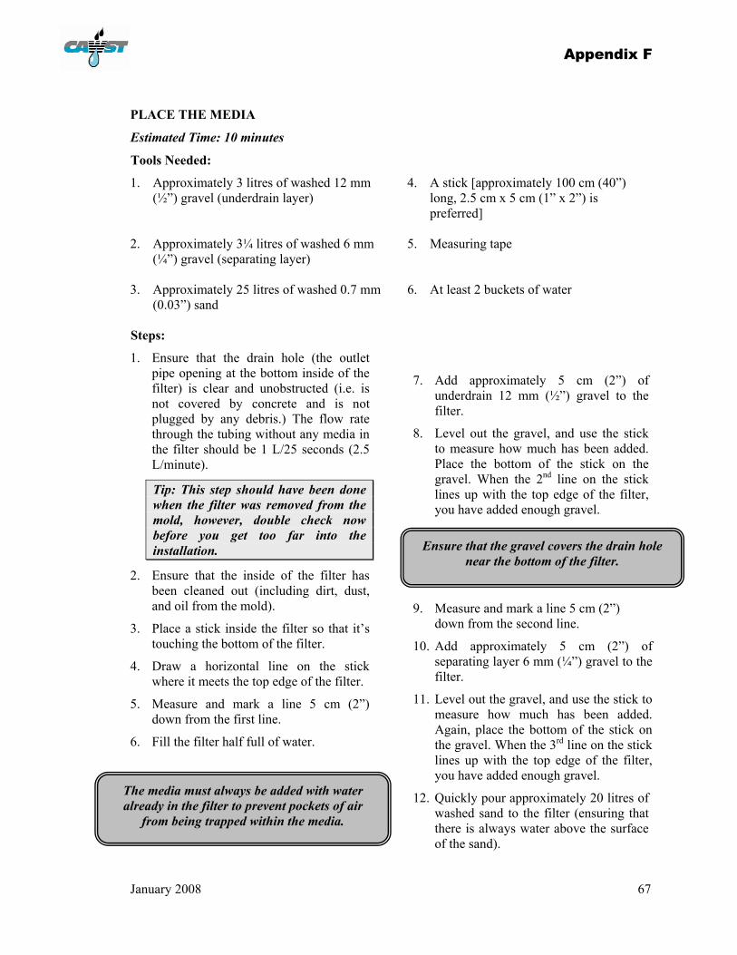
Appendix F
January 2008 67
PLACE THE MEDIA
Estimated Time: 10 minutes
Tools Needed:
1. Approximately 3 litres of washed 12 mm (½”) gravel (underdrain layer)
4. A stick [approximately 100 cm (40”) long, 2.5 cm x 5 cm (1” x 2”) is preferred]
2. Approximately 3¼ litres of washed 6 mm
(¼”) gravel (separating layer)
5. Measuring tape
3. Approximately 25 litres of washed 0.7 mm (0.03”) sand
6. At least 2 buckets of water
Steps:
1. Ensure that the drain hole (the outlet pipe opening at the bottom inside of the filter) is clear and unobstructed (i.e. is not covered by concrete and is not plugged by any debris.) The flow rate through the tubing without any media in the filter should be 1 L/25 seconds (2.5 L/minute).
Tip: This step should have been done when the filter was removed from the mold, however, double check now before you get too far into the installation.
2. Ensure that the inside of the filter has been cleaned out (including dirt, dust, and oil from the mold).
3. Place a stick inside the filter so that it’s touching the bottom of the filter.
4. Draw a horizontal line on the stick where it meets the top edge of the filter.
5. Measure and mark a line 5 cm (2”) down from the first line.
6. Fill the filter half full of water.
7. Add approximately 5 cm (2”) of underdrain 12 mm (½”) gravel to the filter.
8. Level out the gravel, and use the stick to measure how much has been added. Place the bottom of the stick on the gravel. When the 2nd line on the stick lines up with the top edge of the filter, you have added enough gravel.
9. Measure and mark a line 5 cm (2”)
down from the second line.
10. Add approximately 5 cm (2”) of separating layer 6 mm (¼”) gravel to the filter.
11. Level out the gravel, and use the stick to measure how much has been added. Again, place the bottom of the stick on the gravel. When the 3rd line on the stick lines up with the top edge of the filter, you have added enough gravel.
12. Quickly pour approximately 20 litres of washed sand to the filter (ensuring that there is always water above the surface of the sand).
The media must always be added with water already in the filter to prevent pockets of air
from being trapped within the media.
Ensure that the gravel covers the drain hole near the bottom of the filter.
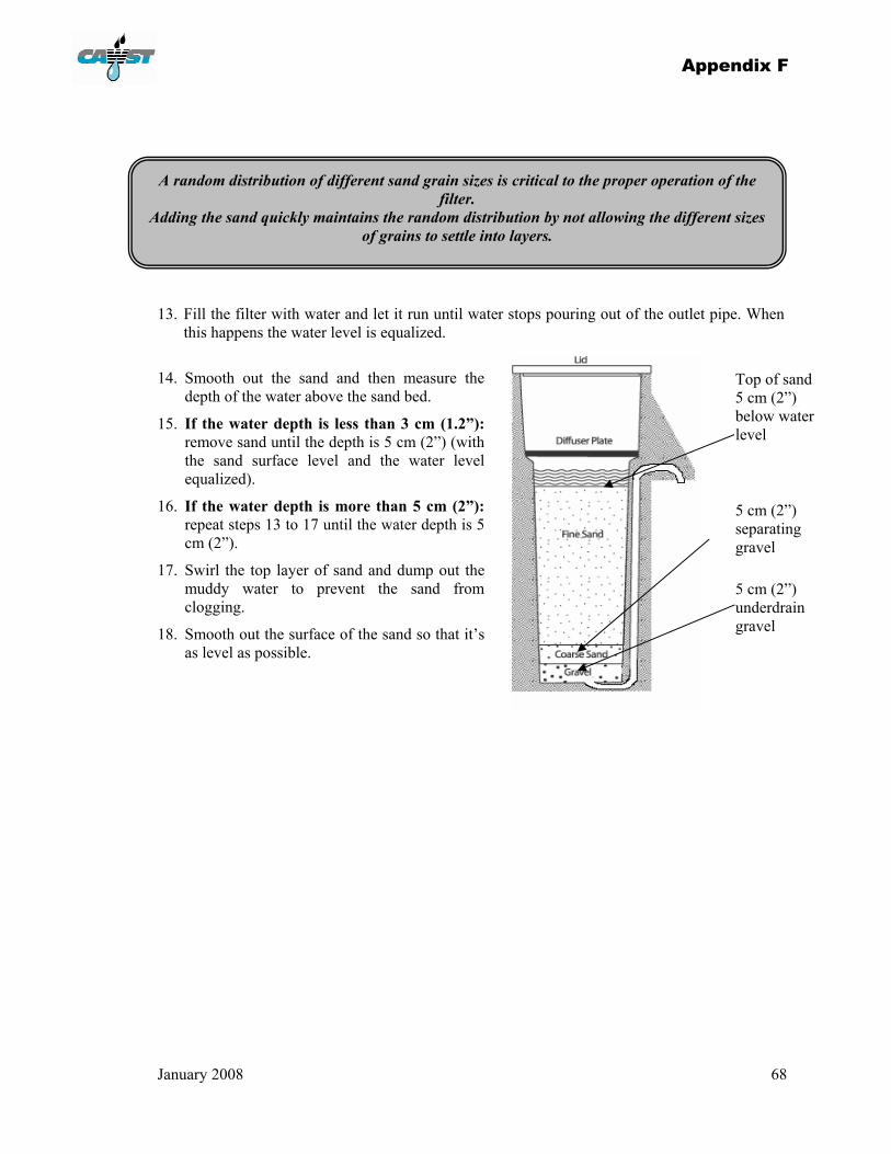
Appendix F
January 2008 68
13. Fill the filter with water and let it run until water stops pouring out of the outlet pipe. When
this happens the water level is equalized.
14. Smooth out the sand and then measure the
depth of the water above the sand bed.
15. If the water depth is less than 3 cm (1.2”): remove sand until the depth is 5 cm (2”) (with the sand surface level and the water level equalized).
16. If the water depth is more than 5 cm (2”): repeat steps 13 to 17 until the water depth is 5 cm (2”).
17. Swirl the top layer of sand and dump out the muddy water to prevent the sand from clogging.
18. Smooth out the surface of the sand so that it’s as level as possible.
5 cm (2”) separating gravel
5 cm (2”) underdrain gravel
Top of sand 5 cm (2”) below water level
A random distribution of different sand grain sizes is critical to the proper operation of the filter.
Adding the sand quickly maintains the random distribution by not allowing the different sizes of grains to settle into layers.
Appendix F
January 2008 69
FLUSH THE FILTER
Estimated Time: 1 hour
Tools Needed:
1. Diffuser 2. 40–80 litres (10–20 gallons) of water
Steps: 1. Place the diffuser plate on the ledge inside the filter. Ensure that it fits snugly.
2. Place a receiving container under the spout. The water that it captures can be reused.
3. Pour the cleanest available water into the filter (turbidity should be less than 50 NTU).
4. Observe the water coming out of the outlet pipe.
5. Continue adding water to the filter until the water coming out is clear. This may take 40-80 litres (10-20 gallons).
The diffuser must not be touching the surface of the water at its resting level.
That would greatly reduce the amount of oxygen in the standing water layer, affecting the survival of the biolayer.
If the outlet water doesn’t run clear after 100 litres (25 gallons), then the gravel or sand was too dirty to start with. It is probably easiest to take the media out, wash it in pails,
and then place it back in the filter.
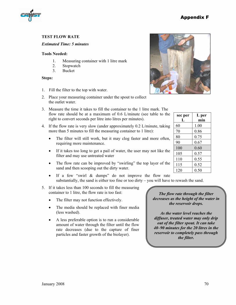
Appendix F
January 2008 70
TEST FLOW RATE
Estimated Time: 5 minutes
Tools Needed:
1. Measuring container with 1 litre mark 2. Stopwatch 3. Bucket
Steps:
1. Fill the filter to the top with water.
2. Place your measuring container under the spout to collect the outlet water.
3. Measure the time it takes to fill the container to the 1 litre mark. The flow rate should be at a maximum of 0.6 L/minute (see table to the right to convert seconds per litre into litres per minutes).
4. If the flow rate is very slow (under approximately 0.2 L/minute, taking more than 5 minutes to fill the measuring container to 1 litre):
• The filter will still work, but it may clog faster and more often, requiring more maintenance.
• If it takes too long to get a pail of water, the user may not like the filter and may use untreated water
• The flow rate can be improved by “swirling” the top layer of the sand and then scooping out the dirty water.
• If a few “swirl & dumps” do not improve the flow rate substantially, the sand is either too fine or too dirty – you will have to rewash the sand.
5. If it takes less than 100 seconds to fill the measuring container to 1 litre, the flow rate is too fast:
• The filter may not function effectively.
• The media should be replaced with finer media (less washed).
• A less preferable option is to run a considerable amount of water through the filter until the flow rate decreases (due to the capture of finer particles and faster growth of the biolayer).
sec per L
L per min
60 1.00 70 0.86 80 0.75 90 0.67 100 0.60 105 0.57 110 0.55 115 0.52 120 0.50
The flow rate through the filter decreases as the height of the water in
the reservoir drops.
As the water level reaches the diffuser, treated water may only drip
out of the filter spout. It can take 40–90 minutes for the 20 litres in the reservoir to completely pass through
the filter.
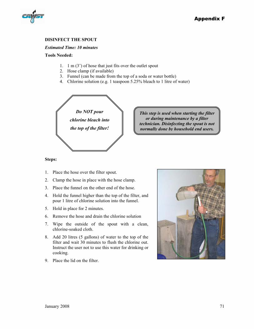
Appendix F
January 2008 71
DISINFECT THE SPOUT
Estimated Time: 10 minutes
Tools Needed:
1. 1 m (3’) of hose that just fits over the outlet spout 2. Hose clamp (if available) 3. Funnel (can be made from the top of a soda or water bottle) 4. Chlorine solution (e.g. 1 teaspoon 5.25% bleach to 1 litre of water)
Steps:
1. Place the hose over the filter spout.
2. Clamp the hose in place with the hose clamp.
3. Place the funnel on the other end of the hose.
4. Hold the funnel higher than the top of the filter, and pour 1 litre of chlorine solution into the funnel.
5. Hold in place for 2 minutes.
6. Remove the hose and drain the chlorine solution
7. Wipe the outside of the spout with a clean, chlorine-soaked cloth.
8. Add 20 litres (5 gallons) of water to the top of the filter and wait 30 minutes to flush the chlorine out. Instruct the user not to use this water for drinking or cooking.
9. Place the lid on the filter.
Do NOT pour
chlorine bleach into
the top of the filter!
This step is used when starting the filter or during maintenance by a filter
technician. Disinfecting the spout is not normally done by household end users.

Appendix F
January 2008 72
ARSENIC REMOVAL
The biosand filter can be easily modified to help remove arsenic from water. If water testing results show unsafe levels of arsenic in the water, then follow the instructions to create a biosand filter that will also remove arsenic.
Materials Needed:
1. 5 kg (11 lb) of non-galvanized iron nails. Small nails are desirable because they give the highest surface area. Ideally, the nails should be less than 20 mm (0.8”) long, but the nails should not be so small that they fall through the holes in the diffuser box. The nails must also be non-galvanized (i.e. iron must rust rapidly) for the arsenic to be effectively removed. Avoid nails that are oily or have visible contamination.
2. Broken pieces of brick or stone of about 5-10 cm (2-4”) diameter. Any type of brick is fine. Bricks should be clean.
Steps:
1. Wash the iron nails to get rid of dust, dirt, stones, oils, and other foreign materials.
2. Wash the brick chips to get rid of dust, dirt, clay powder, and other foreign materials.
3. Place the 5 kg (11 lb) of iron nails in the deep metal box diffuser. It is important that the iron nails is evenly and flatly distributed and cover the entire box bottom.
4. Put one layer of brick chips above the iron nails to completely cover the iron nails. The purpose of the brick chips is to protect the underlying nails from dispersing due to the force of the incoming water.
Note #1:
Do not place a piece of cloth under the iron nails. The cloth will quickly get clogged with iron rust and the flow rate of the filter will be dramatically reduced.
Note #2:
Depending on the nails and the source water, the 3 mm (1/8”) holes may get clogged by iron rust. If so, make the holes bigger using a 5 mm (3/16”) or 6 mm (1/4") nail. However, don’t make the holes so big such that the nails will fall through them.
Appendix F
January 2008 73
OPERATION ESTABLISHING THE BIOLAYER
• The biolayer is the key pathogen removing component of the filter.
• Without it, the filter removes some contamination through screening of the particles and pathogens (only 30-70% removal efficiency).
• A good biolayer will remove 90-99% of the pathogens.
• It may take up to 30 days to establish the biolayer.
• The water from the filter can be used during the first few weeks while the biolayer is being established if a safer water source is not available, but disinfection, as always, is recommended during this time.
• The biolayer is NOT usually visible – it is not a green slimy coating on top of the sand.
DAILY USE
All household users, including children, need to be taught how and why the filter works and about its correct operation and maintenance. Children are frequently the main users of the filter.
• Use the filter every day to, at least 20 litres, twice per day.
• Use the same source of water every day to improve the filter effectiveness.
• Use the best source of water (least contaminated) that is available – the better the source water, the better the treated water will be.
• The turbidity of the source water should be less than 50 NTU. If it is more turbid, then sediment or strain the water before using the biosand filter.
• The diffuser plate must always be in place when pouring water into the filter – never pour water directly onto the sand layer. Slowly pour the water into the filter.
• The lid should always be kept on the filter.
• Use a dedicated bucket for fetching the source water.
• Use a dedicated safe storage container to hold the filtered water which has:
a small opening to prevent recontamination due to dipping with cups or hands a tap or spigot.
• Place the receiving container as close to the spout as possible (i.e. place it on a block) to reduce dripping noise and prevent recontamination.
The dripping noise can be irritating. The closer you place the container to the spout, the less noise there is. A container with a small opening also reduces dripping noise.
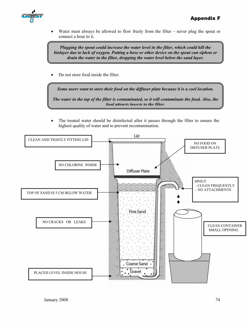
Appendix F
January 2008 74
• Water must always be allowed to flow freely from the filter – never plug the spout or connect a hose to it.
• Do not store food inside the filter.
• The treated water should be disinfected after it passes through the filter to ensure the highest quality of water and to prevent recontamination.
CLEAN AND TIGHTLY FITTING LID
SPOUT - CLEAN FREQUENTLY - NO ATTACHMENTS TOP OF SAND IS 5 CM BELOW WATER
NO CRACKS OR LEAKS
PLACED LEVEL INSIDE HOUSE
CLEAN CONTAINER SMALL OPENING
NO CHLORINE INSIDE
NO FOOD ON DIFFUSER PLATE
Plugging the spout could increase the water level in the filter, which could kill the biolayer due to lack of oxygen. Putting a hose or other device on the spout can siphon or
drain the water in the filter, dropping the water level below the sand layer.
Some users want to store their food on the diffuser plate because it is a cool location.
The water in the top of the filter is contaminated, so it will contaminate the food. Also, the food attracts insects to the filter.
Appendix F
January 2008 75
MAINTENANCE There is some key maintenance that is required after a filter has been installed and used regularly. DISINFECTION
The outlet spout will become contaminated during normal use via dirty hands, animals, or insects.
Steps:
• Clean the filter outlet spout regularly with soap and water or a chlorine solution.
• Clean the inside of the treated water storage container when it looks dirty, when you do regular maintenance or at least once a month. Do NOT pour chlorine bleach into the top of the filter! To clean the storage container: o Wash your hands before cleaning the container o Scrub the inside of the container with soap and treated water o Empty the soapy water through the tap o Rinse the container with a little treated water o Add chlorine to water in the storage container – let it sit for 30 minutes – if chlorine
is not available, let the container air dry o Empty the remaining water through the tap o Clean the tap with a clean cloth and chlorine solution (such as bleach)
• The entire filter should be cleaned regularly (lid, diffuser, outside surfaces).
SWIRL & DUMP
The flow rate through the filter will slow down over time as the biolayer develops and sediment is trapped in the upper layer of the sand. Users will know when the “swirl & dump” is required because the flow rate will drop to an unacceptable level. The filter is still effectively treating the water at this point; however the length of time that it takes to get a bucket of water may become too long and be inconvenient for the user. Alternately, you can measure the flow rate and if it is less than 0.1 L/minute, “swirl & dump” maintenance is required.
Steps:
1. Remove the lid of the filter.
2. Add 4 litres (1 gallon) of water to the top of the filter.
3. Remove the diffuser.
4. “Swirl” a small wooden stick or spoon around in the standing water at least 5 times – the water will become dirty. Work the stick into the sand layer about 2 cm (0.8”) while “swirling” around across the entire surface area of the sand, but do not mix the surface layer any deeper than 5 cm (2”) into the filter.
5. Scoop out the dirty water with a small container (i.e. a cup or a pop bottle cut in half).
6. Dump the dirty water outside the house in an appropriate location, such as a soak pit or garden (remember it is contaminated water).
7. Smooth and level the sand surface.
8. Replace the diffuser.
9. Pour 20 litres (5 gallons) of water into the top of the filter.

Appendix F
January 2008 76
10. Measure the flow rate.
11. If the flow rate is less than 0.6 L/minute, repeat steps 1 through 10 until the flow rate is acceptable.
12. Wash your hands with soap and clean water - you have been handling contaminated water.
FOLLOW UP VISITS
Follow-up visits with the household users should be done to ensure proper use and maintenance of the filters. The first follow up visit should be during the first two weeks of use and then every 1-2 months thereafter. During follow up visits, ensure that the filter is being operated and maintained as described above. The following general checks can be made at any time by the users, Community Health Worker, or Filter Technician that is active in the area:
• Check that the filter is in an appropriate location (indoors, protected from the weather, animals, and insects) and is level.
• Look for drips of water or wet spots under the filter, which indicate a leak in the concrete box.
• Check that the lid is tight fitting and clean on the inside and outside.
• Make sure the diffuser is clean and it is sitting properly on the concrete lip.
• Make sure the holes in the diffuser are not plugged – periodic cleaning may be needed.
• Check that the surface of the sand is smooth and level (use a small straight object to smooth the sand ONLY if necessary).
• Make sure the surface of the sand is 5 cm (2”) below the water level.
The sand may settle over time and more will have to be added. Add (or remove) sand if the standing water depth is not 5 cm (2”).
This is not usually a task that will be done by the household user. The sand must be the correct size and clean. Sand should be provided by the Filter Technician or
Community Health Promoter.

January 2008 77
APPENDIX G: FILTER CONSTRUCTION CHECKLIST
Cut and bend the outlet pipe tubing to size; then cover the end with tape.
Clean, oil, and then assemble the mold. Do not oil the top of the inner mold and do not oil connecting pieces.
Insert and hand tighten all bolts; then tighten all bolts with a wrench.
Place the tubing in the mold. Ensure the tubing is placed down the middle of the wall. Position the nose plate with the tubing sticking through, tighten the set screw and plug the standpipe outlet.
Tape the tubing onto the interior mold to hold it in place.
Use a level and wooden shims to make the mold level.
Measure and mix 12 L of Portland cement, 24 L of sieved sand, 12 L of sieved 12mm (½”) gravel, and 12 L of 6 mm (¼”) gravel, adding water gradually while mixing to make a fairly stiff mix (about 7 litres of water). Quantities may vary depending on the exact size of the mold and the moisture content of the sand. Generally a ratio of 1:2:1:1 is recommended.
Shovel concrete into the mold, a few shovel-fulls at a time.
Use a long metal rod (such as rebar) as a tamper and hit the outside of the mold with the mallet in an upward pattern.
As you fill the last of the mold, check the tubing to be sure it has not moved.
Fill the filter with excess concrete and allow the concrete to slump for 30 minutes.
Jab your trowel 10 cm (4”) into the concrete, all around the inner mold, to ensure the last bit of concrete mixes (mallet briefly).
Smooth away the excess concrete, leaving 1.2 cm (½”) over the wall and bevel edge, with a flat board and then trowel it, to leave a flat surface.
Wait 18-24 hours, no longer (weather dependant)
Remove the nose plate. Turn the mold upside down, using a tire or a
sack of grain to support the mold. Remove the bolts on top of the mold. Do not
loosen any of the side bolts yet. Hit the top of the mold with a mallet to
loosen the bond with the concrete. Place the puller assembly on top of the mold,
lubricate, and clean threads. Tighten the centre bolt (by turning it
clockwise) until it is well threaded into the nut on the mold.
Tighten the nut above the puller by turning it clockwise until the interior mold releases.
Carefully remove the interior mold and store it safely.
Remove the remaining bolts and the 3-sided panel; then remove the front (nose) panel.
Clean and oil the mold. Remove excess tape that covers the tubing
opening in the interior of the filter. Check both ends of the tubing to ensure they
have not been plugged by concrete. Depending on the mold, if the tubing extends
more than 1.2 cm (½”) out of the concrete nose, cut it to less than 1.2 cm (½”) in length.
Fill the filter with water. The flow rate should be about 2.5 L/minute. Check for cracks in the filter.
Plug the tube. Fill the filter with water for 5-7 days while it
cures. Do not transport the filter during that time.
Before installation, scrub the inside of the filter out with a broom or scrub brush, soap and water.
Fill out the filter production record (see Appendix J).

January 2008 78
APPENDIX H: QUALITY CONTROL CHECKLIST A) FILTER BODY (While the filter is being built)
Good quality cement has been used (not been exposed to moisture).
Clean, good quality sand and gravel is used in concrete.
Plastic or copper 6 mm (¼”) I.D. tubing is used.
Mold is straight, square, smooth, and well oiled to ensure the filter comes out easily.
Concrete is cured by keeping damp for 5-7 days.
Inside of mold is clean with no cement or oily residue except for where the seal and joints are located.
Filter is protected during transportation and final placement.
Water flows out spout before sand is added at approximately 2.5 L/minute.
Water level is below diffuser lip a minimum of 10 mm (1/2”).
Outside surface of the filter looks attractive and clean (washed and painted if desired).
B) MEDIA PREPARATION
Sieves have good quality screen with no holes or tears.
12 mm (½”) and 6 mm (¼”) gravel is properly cleaned.
Washed sand meets flow rate test.
Sand is protected after sieving, washing and during transportation (covered, inside or bagged).
C) INSTALLATION
Filter is level at final installation location.
Large gravel covers tubing.
Water is in filter body before sand is added. After placing the gravel ensure the water flows.
Final sand level is 5 cm (2”) below the resting water level.
The ideal flow rate of the filter is 0.6 L/minute, when the top reservoir is full of water.
Lid fits tightly on top of filter.
Lid has a handle.
Diffuser fits properly onto diffuser lip.
Diffuser plate material is strong enough to withstand the force of pouring water.
The Product Manufacturer/Filter Technician provides a full instruction of the proper operation and maintenance of the filter.
Use and maintenance poster, brochure or sticker is left with the user.
Arrangement or a time is set for a follow-up visit.

January 2008 79
APPENDIX I: INSTALLATION CHECKLIST GENERAL
Confirm delivery time and place.
Make sure filter is completely clean and ready to go.
Check filter for leaks.
Ensure the media is washed.
FILTER
Diffuser (with handle or bring wire for handle).
Nails for arsenic version of filter, 5 kg (11 lb).
Lid.
Washed sand (approximately 25 litres).
Washed underdrain gravel (approximately 3 litres).
Washed separating gravel (approximately 3¼ litres).
TRANSPORTATION
Cart.
Strapping.
Packing material to prevent filters from breaking (e.g. straw, newspaper, carpet, etc).
Plastic sheet or tarp. INSTALLATION
Leveling shims.
Small bucket.
Hose clamp.
Hose
Funnel.
Disinfection solution
2 buckets of water – minimum.
TOOLS
1 litre measuring container.
Watch.
Level.
Hacksaw.
Gloves.
Knife.
Pliers.
Tape measure.
Marker (to mark number & date).
Flashlight (optional).
DOCUMENTATION
“How to use and maintain your biosand filter” poster, pamphlet or sticker to be left with user.
Receipt book.
Installation record form.
Clipboard and pen.

January 2008 80
APPENDIX J: FILTER PRODUCTION RECORD
Production Date
Demold Date
Filter Number
Mold Number
Flow Rate Comments Technician
Initials

January 2008 81
APPENDIX K: COSTING AND PRICING FORM (1)
BIOSAND FILTER COSTING AND PRICING FORM
For Internal Use Only
Description of Material Quantity Used
Price per Unit
Cost of Quantity
Used
Travel Time to pick up materials
Direct Materials Used - Total Cost
Direct Labour Costs Hours Cost per
Hour Subtotal
Filter Fabrication Filter Installation
Direct Labour – Total Cost Total Direct Costs
Overhead ( %)
Total Indirect Costs
Profit Margin ( %)
PRODUCT PRICE Before Delivery
Delivery to customer location
FINAL DELIVERED AND INSTALLED PRODUCT PRICE

January 2008 82
APPENDIX L: COSTING AND PRICING FORM (2)
Materials Used Quantity Purchased
Cost of Purchases Quantity Used Cost Per Filter
Total cost of materials used: Labour Costs Cost Per Filter
Total Labor Costs: Transport Costs Cost Per Filter
Total transport costs:
Total direct costs (materials, labor, transport) Profit Margin ( % of direct costs): Overhead costs ( % of direct costs):
PRICE OF
FILTER:
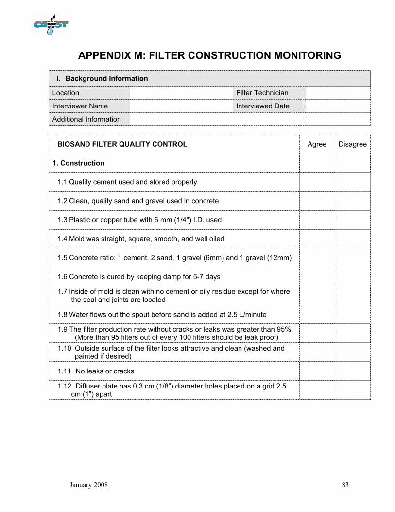
January 2008 83
APPENDIX M: FILTER CONSTRUCTION MONITORING
I. Background Information
Location Filter Technician
Interviewer Name Interviewed Date
Additional Information
BIOSAND FILTER QUALITY CONTROL Agree Disagree
1. Construction
1.1 Quality cement used and stored properly
1.2 Clean, quality sand and gravel used in concrete
1.3 Plastic or copper tube with 6 mm (1/4") I.D. used
1.4 Mold was straight, square, smooth, and well oiled
1.5 Concrete ratio: 1 cement, 2 sand, 1 gravel (6mm) and 1 gravel (12mm)
1.6 Concrete is cured by keeping damp for 5-7 days
1.7 Inside of mold is clean with no cement or oily residue except for where the seal and joints are located
1.8 Water flows out the spout before sand is added at 2.5 L/minute
1.9 The filter production rate without cracks or leaks was greater than 95%. (More than 95 filters out of every 100 filters should be leak proof)
1.10 Outside surface of the filter looks attractive and clean (washed and painted if desired)
1.11 No leaks or cracks
1.12 Diffuser plate has 0.3 cm (1/8”) diameter holes placed on a grid 2.5 cm (1”) apart
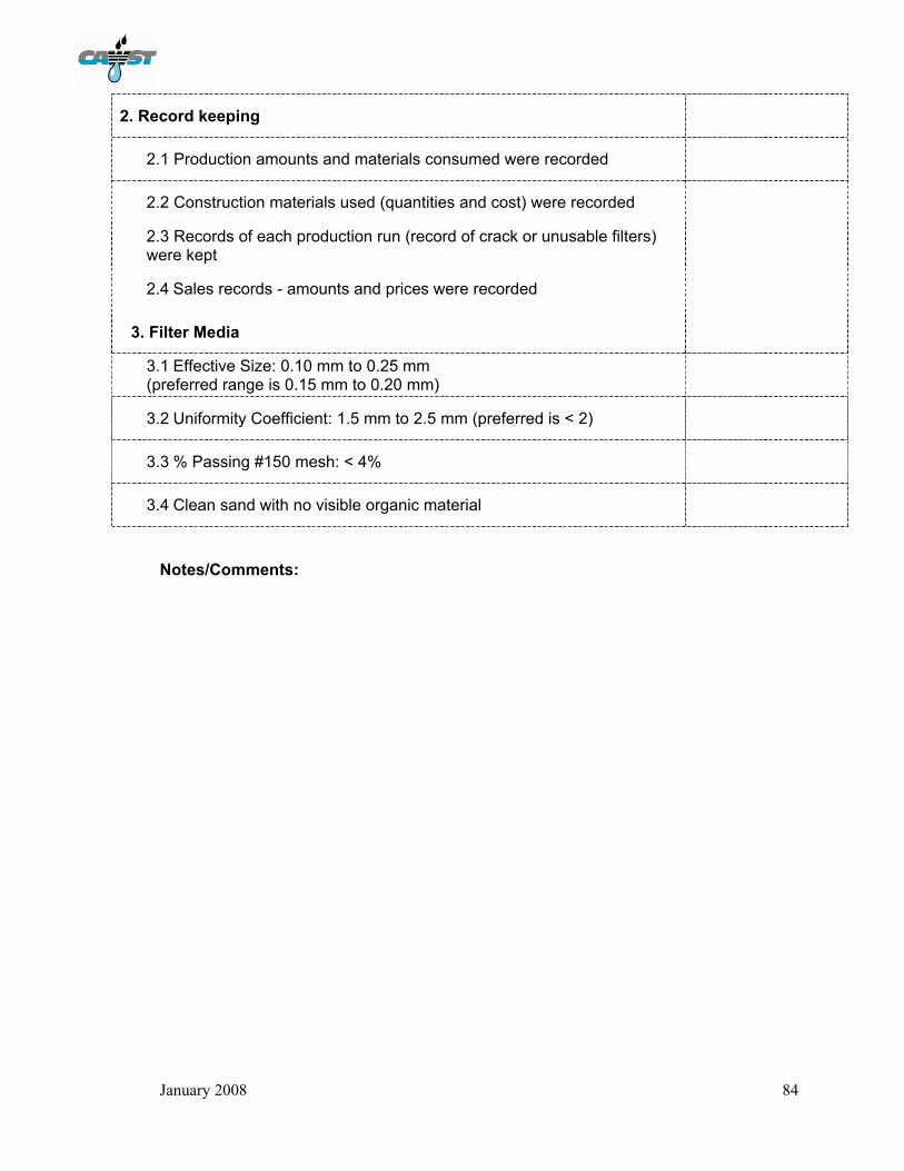
January 2008 84
2. Record keeping
2.1 Production amounts and materials consumed were recorded
2.2 Construction materials used (quantities and cost) were recorded
2.3 Records of each production run (record of crack or unusable filters) were kept
2.4 Sales records - amounts and prices were recorded
3. Filter Media
3.1 Effective Size: 0.10 mm to 0.25 mm (preferred range is 0.15 mm to 0.20 mm)
3.2 Uniformity Coefficient: 1.5 mm to 2.5 mm (preferred is < 2)
3.3 % Passing #150 mesh: < 4%
3.4 Clean sand with no visible organic material
Notes/Comments:

January 2008 85
APPENDIX N: HOUSEHOLD MONITORING
II. Background Information
Location Household Name
Interviewer Name Interviewed Date
Additional Information
Yes No
1. Quality of Construction
1.1 Are there any leaks on the concrete filter body?
1.2 Is there a lid which covers the entire filter body?
1.3 Is there a diffuser plate without cracks or damage?
2. Proper Installation
2.1 Is the filter in a suitable location away from weather and animals?
2.2 Is this surface of the sand flat and level?
2.3 What is the depth of the water above the sand? __________ cm
2.4 What is the flow rate of the filter? ________ seconds/Litre
2.5 Is the water coming out of the filter clear?
3. Proper Use
3.1 Is there a valve or tube attached to the outlet of the fitler?
3.2 Is the outlet of the filter clean?
3.3 How often is the filter being used? Every 1 or 2 days ________ Every 3rd day or less ________

January 2008 86
4. Safe Water Storage
4.1 Does storage container have a lid?
4.2 Does the storage container have a tap or narrow opening to pour out the water?
4.3 Is the storage container clean (e.g. free of dirt and algae)?
4.4 Does the household use different containers for collecting and storing water?
Notes/Comments:

January 2008 87
APPENDIX O: SAND SIEVE ANALYSIS Introduction Most sand sieve analysis is performed by measuring the weight of the sand passing through (or retained by) each sieve. However, in many field situations weight scales are not available or dependable for this analysis. Sand sieve analyses using volume measurements rather than weight minimizes the equipment required while still providing adequate results for analyzing sand for biosand filters. Note that this is not an approved standard procedure but rather a workable field method for rapid assessment. This analysis should be carried out after the sand has been washed to remove organic material and very fine sand (‘rock flour’). Alternatively, this method can also be used to assess a potential sand source to determine if it would be suitable for use as biosand filter media. All sand samples must be totally dry before sieving. Materials Required
1. Sand sample: at least 100 mL of very dry sand (the sample must be representative of sand to be analyzed)
2. Graduated cylinder: 100 mL size, with 1 mL markings, plastic is recommended. 3. Set of sieve screens (‘wire mesh’):
• #24 sieve (opening size = 0.710 mm) • #40 sieve (opening size = 0.425 mm) • #60 sieve (opening size = 0.250 mm) • #80 sieve (opening size = 0.180 mm) • #150 sieve (opening size = 0.104 mm) • Catch pan (to catch all sand that passes #150 sieve size) • Sieve set lid (placed above the #24 sieve to contain the sand while sieving)
4. Semi-log graph paper (provided in Appendix O), pencil (or erasable ink pen) and ruler. Instructions
1. Stack the sand sieves with the coarsest (#24) on top followed by the #40, #60, #80, #150 and finally the Catch pan on the bottom.
2. Fill the graduated cylinder to the 100 mL mark with the dry sand sample. Use a piece of paper,
rolled or folded, as a ‘funnel’ to make it easier to fill the graduated cylinder.
3. Empty the entire 100 mL sample from the graduated cylinder onto the top sieve (#24) and place the lid on top of the top sieve.
4. Shake the entire sieve column, including the bottom catch pan and top lid, for five minutes. Shake both sideways and up and down to ensure the sand is allowed to fall through the various screens. After 5 minutes, remove the top lid and place the sand from the #24 sieve into the graduated cylinder. Use a piece of paper as a funnel to direct the sand into the cylinder. Read the amount of sand in the graduated cylinder. Do not pour out the sand from the cylinder afterwards. In the table on the semi-log graph paper provided in Appendix O, record the value in the column; Cumulative Sand Retained for the #24 sieve.
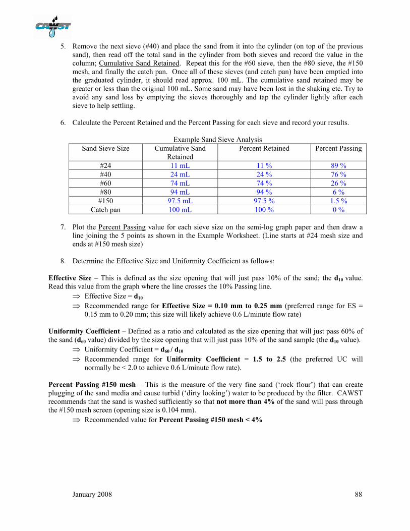
January 2008 88
5. Remove the next sieve (#40) and place the sand from it into the cylinder (on top of the previous
sand), then read off the total sand in the cylinder from both sieves and record the value in the column; Cumulative Sand Retained. Repeat this for the #60 sieve, then the #80 sieve, the #150 mesh, and finally the catch pan. Once all of these sieves (and catch pan) have been emptied into the graduated cylinder, it should read approx. 100 mL. The cumulative sand retained may be greater or less than the original 100 mL. Some sand may have been lost in the shaking etc. Try to avoid any sand loss by emptying the sieves thoroughly and tap the cylinder lightly after each sieve to help settling.
6. Calculate the Percent Retained and the Percent Passing for each sieve and record your results.
Example Sand Sieve Analysis
Sand Sieve Size Cumulative Sand Retained
Percent Retained Percent Passing
#24 11 mL 11 % 89 % #40 24 mL 24 % 76 % #60 74 mL 74 % 26 % #80 94 mL 94 % 6 %
#150 97.5 mL 97.5 % 1.5 % Catch pan 100 mL 100 % 0 %
7. Plot the Percent Passing value for each sieve size on the semi-log graph paper and then draw a
line joining the 5 points as shown in the Example Worksheet. (Line starts at #24 mesh size and ends at #150 mesh size)
8. Determine the Effective Size and Uniformity Coefficient as follows:
Effective Size – This is defined as the size opening that will just pass 10% of the sand; the d10 value. Read this value from the graph where the line crosses the 10% Passing line.
⇒ Effective Size = d10 ⇒ Recommended range for Effective Size = 0.10 mm to 0.25 mm (preferred range for ES =
0.15 mm to 0.20 mm; this size will likely achieve 0.6 L/minute flow rate) Uniformity Coefficient – Defined as a ratio and calculated as the size opening that will just pass 60% of the sand (d60 value) divided by the size opening that will just pass 10% of the sand sample (the d10 value).
⇒ Uniformity Coefficient = d60 / d10 ⇒ Recommended range for Uniformity Coefficient = 1.5 to 2.5 (the preferred UC will
normally be < 2.0 to achieve 0.6 L/minute flow rate).
Percent Passing #150 mesh – This is the measure of the very fine sand (‘rock flour’) that can create plugging of the sand media and cause turbid (‘dirty looking’) water to be produced by the filter. CAWST recommends that the sand is washed sufficiently so that not more than 4% of the sand will pass through the #150 mesh screen (opening size is 0.104 mm).
⇒ Recommended value for Percent Passing #150 mesh < 4%

January 2008 89
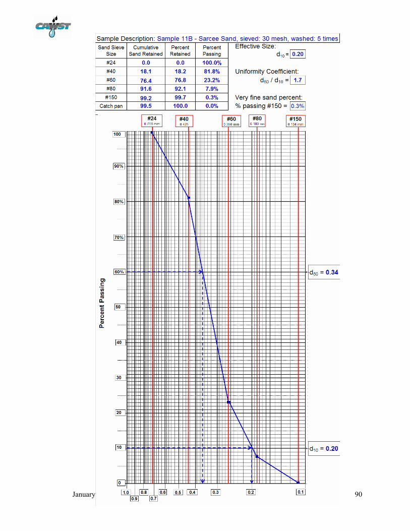
January 2008 90