bipoleiii: past, present and...
TRANSCRIPT
Bipole III: Past, Present and Future
David Jacobson, Section Head‐ Interconnection Planning, System Planning, Manitoba Hydro
November 13, 2019
2019 Minnesota Power Systems Conference
Outline• Introduction• Early Planning Studies • Bipole III Need• Bipole III Project Scope• Bipole III Future• Video• Q&A
2
Introduction
3

• Crown Corporation (owned by Prov. MB) with head office at Winnipeg.
• Services for over 580,000 electricity and 280,000 gas customers.
• A total generating capacity about 5700 MW produced mainly by 15 hydroelectric stations, 2 wind plants and 2 thermal stations.
Manitoba Hydro
4 https://www.manitobahydropower.com/who‐we‐are/
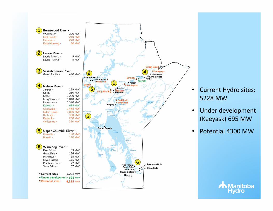
• Current Hydro sites: 5228 MW
• Under development (Keeyask) 695 MW
• Potential 4300 MW

Interconnections
• B71T ‐ Birtle to Tantallon 2021• D604I – Dorsey to Iron Range
2020 (MMTP/GNTL)
Limestone
Kettle
Jenpeg
Selkirk
Brandon
Grand Rapids
Dorsey
Riel
Keewatinohk
R7B –1960
M602F‐1980; D604IR50M‐1976
SK1 – 1956K21W – 1972K22W – 1973
R25Y –1972
P52E –1979
I1/2F –1929
G82P –2002
L20D –1970
B71T

Firm Export/Import Capability
Export Import
U.S.* 1950 MW2833 MW
700 MW1398 MW
Ontario 200 MW 0 MW
Sask-south
Sask-north
150 MW290 MW25 MW
0 MW0 MW60 MW
https://www.oasis.oati.com/woa/docs/MHEB/MHEBdocs/2016_Transmission_Interface_Capability_Report.pdf
ManitobaSask
Alberta
Ontario
MISO
150 MW 200 MW
1950 MW
25 MW
* Excludes 150 MW CRSG

Early Planning Studies
8

1960’s
• 1963 – Government of Canada/Manitoba shared cost of study looking at development of the Nelson River.
• 1966 – Agreed to jointly develop Phase 1 –“Birth of HVDC in Manitoba”
• Phase 1 – 1272 MW Kettle (ISD 1974), two 900 km HVDC lines, Bipole I (ISD June 1972),
9
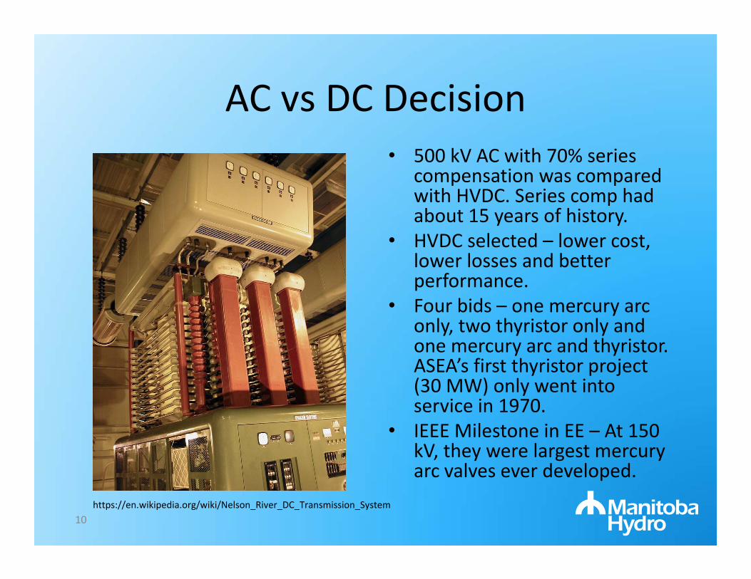
AC vs DC Decision• 500 kV AC with 70% series
compensation was compared with HVDC. Series comp had about 15 years of history.
• HVDC selected – lower cost, lower losses and better performance.
• Four bids – one mercury arc only, two thyristor only and one mercury arc and thyristor. ASEA’s first thyristor project (30 MW) only went into service in 1970.
• IEEE Milestone in EE – At 150 kV, they were largest mercury arc valves ever developed.
10https://en.wikipedia.org/wiki/Nelson_River_DC_Transmission_System

1970s Projections
• High load growth projected need for Bipole III as early as 1988.
• A nuclear engineering department was formed in 1974.
11
C.V. Thio, “Nelson River HVdc Bipole‐Two Part 1‐System Aspects, IEEE Trans. PAS, Vol. PAS‐98, No. 1, Jan/Feb 1979.
Bipole IIBipole III
Bipole I

1980’s
• Load growth slowed• Completed development
of Bipole II in June 1985.• 2000 MW, 500 kV
thyristor technology• Long Spruce completed
1979.• Limestone’s original
target year was 1983 –deferred to 1990.
12https://en.wikipedia.org/wiki/Nelson_River_DC_Transmission_System

Early 1990s• Potential for a 1000 MW to sale to Ontario moved up the schedule for Bipole III and Conawapa.
• Agreement signed in 1989 and cancelled in 1992.
13
Conawapa
Winnipeg
Dryden
LakeheadTimmins
Sudbury
Bipole 3820 km
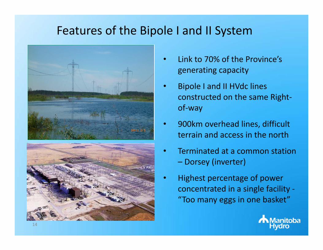
• Link to 70% of the Province’s generating capacity
• Bipole I and II HVdc lines constructed on the same Right‐of‐way
• 900km overhead lines, difficult terrain and access in the north
• Terminated at a common station – Dorsey (inverter)
• Highest percentage of power concentrated in a single facility ‐“Too many eggs in one basket”
Features of the Bipole I and II System
14

External Asynchronous Resource (EAR)
• Bipoles I and II allows for hydro to look like a battery. Allows for hydro‐wind synergy. Very fast ramping capability.
• EAR is a market‐designated resource separated from the main MISO market by a DC tie.
• EAR is very flexible and can provide energy, spinning, supplemental regulating reserves, regulation, ramp products, capacity.
• Currently, EAR is bidirectional and limited to 375 MW. Available since ~2010.
15

Bipole III Need
16

Why is Bipole III required now?
• Bipole III is required for reliability• Bipole I & II DC transmission line corridor loss• Only one southern converter station (Dorsey)• Long restoration times
• We’ve experienced loss of corridor before and near misses (downbursts, ice, forest fires and etc.).• Real risks, not theoretical
17
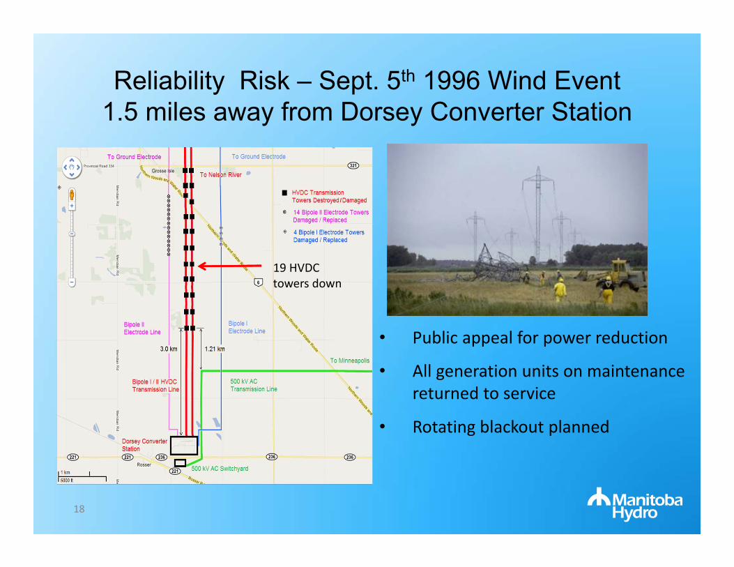
Reliability Risk – Sept. 5th 1996 Wind Event1.5 miles away from Dorsey Converter Station
19 HVDC towers down
18
• Public appeal for power reduction
• All generation units on maintenance returned to service
• Rotating blackout planned

Reliability Risk – Dorsey Converter Station
• Dorsey is a single terminus point for HVDC system
• Significant weather events (tornados, etc.) in the vicinity of Dorsey in the past
• A complete loss at Dorsey could mean loss of connection to northern generation for up to 3 years.
19
Elie F5 Tornado
Storm hits portions of Dorsey, Aug. 10, 2007; Lost BPI followed by D602F 60 seconds later
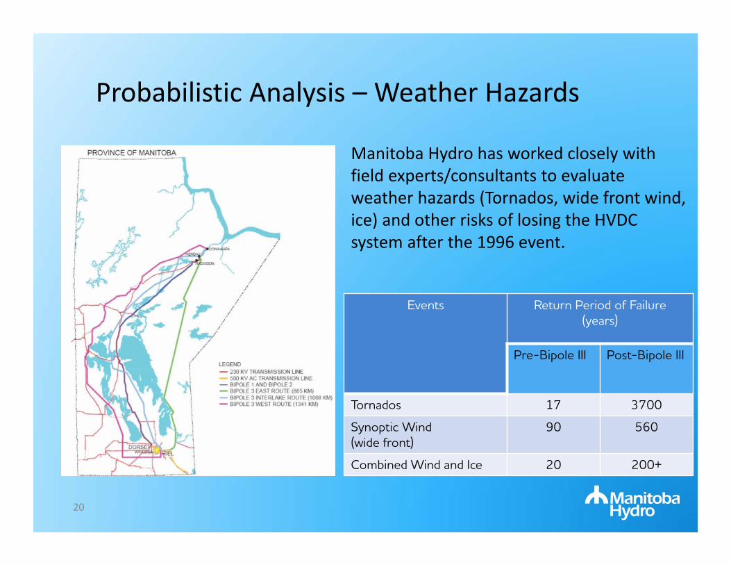
Probabilistic Analysis – Weather Hazards
Manitoba Hydro has worked closely with field experts/consultants to evaluate weather hazards (Tornados, wide front wind, ice) and other risks of losing the HVDC system after the 1996 event.
20
Events Return Period of Failure (years)
Pre-Bipole III Post-Bipole III
Tornados 17 3700
Synoptic Wind(wide front)
90 560
Combined Wind and Ice 20 200+
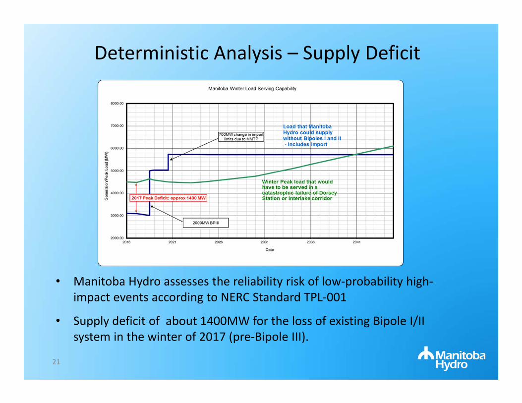
Deterministic Analysis – Supply Deficit
• Manitoba Hydro assesses the reliability risk of low‐probability high‐impact events according to NERC Standard TPL‐001
• Supply deficit of about 1400MW for the loss of existing Bipole I/II system in the winter of 2017 (pre‐Bipole III).
21
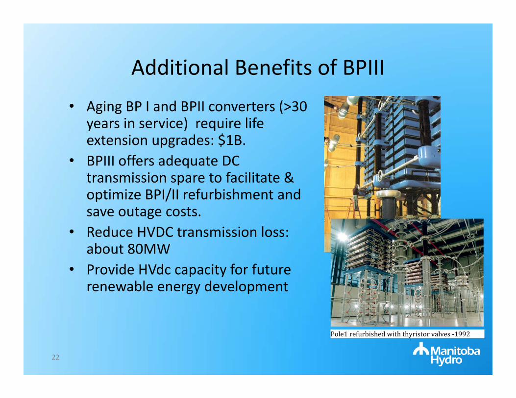
Additional Benefits of BPIII• Aging BP I and BPII converters (>30
years in service) require life extension upgrades: $1B.
• BPIII offers adequate DC transmission spare to facilitate & optimize BPI/II refurbishment and save outage costs.
• Reduce HVDC transmission loss: about 80MW
• Provide HVdc capacity for future renewable energy development
Pole1refurbishedwiththyristorvalves‐1992
22

2000’s• 2001: Internal report recommends:
– Building 800 km East side HVdc line by 2010– Sectionalization of D602F at Riel in 2008.– Bipole I and II lines would be paralleled on
BP I. Bipole III line would terminate at Dorsey on BP II.
• In 2005, East side becomes unavailable as an application to designate area as a UNESCO world heritage site in progress.
• Decision made in 2007 to proceed with Western route. New DC converters added to scope as impedance of 1388 km route expected to be difficult for Bipole II analog controls.

Bipole III Project Scope
24

Bipole III Planning Studies
• Power flow studies
• Fault studies
• Stability studies
• Ac and DC harmonic studies
• Small signal stability assessment
• Feasibility studies of VSC technology
25

Outcome of Bipole III Planning Studies
• Determine BPIII size and operation modes
• Ac system reinforcement for integration of BPIII (new lines/stations, location, upgrades, etc.)
• Static/dynamic reactive power requirements
• Determine equipment rating (breakers, switches, grounding and etc.)
• Estimation of ESCR and MIESCR for dc performance and determine mitigation
• Determine impact on the nearby systems (ac and dc in multi‐infeed schemes)
• Determine special requirements (supplementary damping /fast dc reductions)
26

Feasibility Study ‐ VSC Option
• No commutation failure‐ Large infeed of HVdc schemes in proximity: If all LCC links fail commutation at the same time, it can lead to potential (although very short) loss of significant power to southern system. ‐ VSC improves this situation by not failing commutation and ability to maintain power flow.
• No synchronous condensers‐ Cost savings : Capital /O&M ‐ Reduce system fault levels‐ VSCs can provide voltage and reactive power support, but not inertia that synchronous condensers do
27

Feasibility Study ‐ VSC Option
• Decision‐ Permit VSC bids as an option‐ Included price break as 4x250 MVAr synchronous condensers not required.
‐ Required dc faults to be cleared on dc side (full bridge or dc breaker needed).
• Disadvantages‐ Not implemented at 500 kV and 2300 MW; Skagarak 4 planned for
2014‐ Limited number of vendors‐ Dc fault clearing requires ac breakers (half bridge technology)‐ Converter losses slightly 1% vs 0.7%
28

Bipole III Project Scope ‐ ISD 2018LCC, ±500 kV, 2000 MW
29
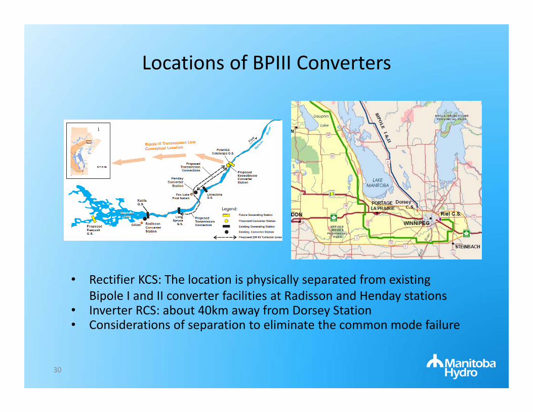
Locations of BPIII Converters
• Rectifier KCS: The location is physically separated from existing Bipole I and II converter facilities at Radisson and Henday stations
• Inverter RCS: about 40km away from Dorsey Station • Considerations of separation to eliminate the common mode failure
30
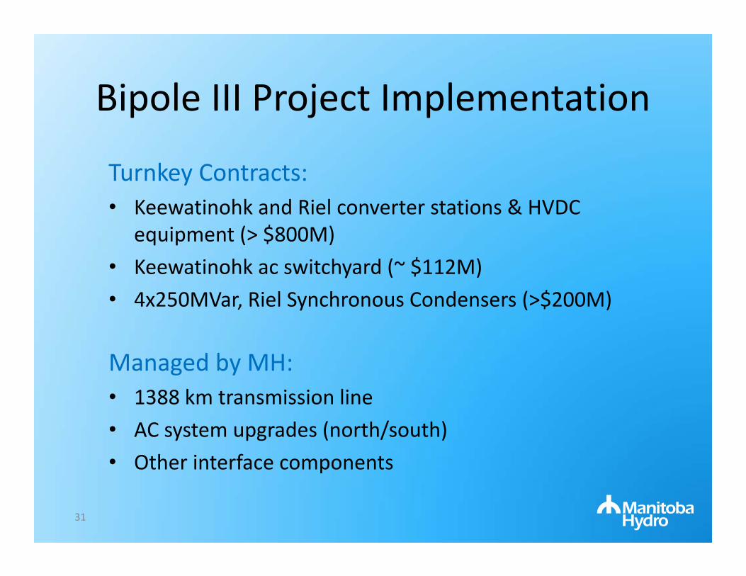
Bipole III Project Implementation
31
Turnkey Contracts:• Keewatinohk and Riel converter stations & HVDC
equipment (> $800M)• Keewatinohk ac switchyard (~ $112M)• 4x250MVar, Riel Synchronous Condensers (>$200M)
Managed by MH:• 1388 km transmission line • AC system upgrades (north/south)• Other interface components
Project Scope ‐ Converter Stations
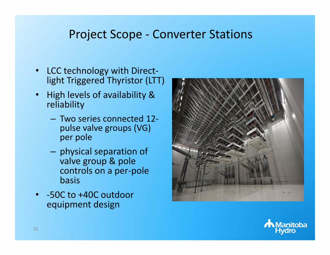
• LCC technology with Direct‐light Triggered Thyristor (LTT)
• High levels of availability & reliability– Two series connected 12‐
pulse valve groups (VG) per pole
– physical separation of valve group & pole controls on a per‐pole basis
• ‐50C to +40C outdoor equipment design
32

Project Scope ‐ Converter Stations
• Nominal power transfer capacity of 2000 MW with 115% continuous overload
• Transient overload capability of 1.27pu for damping purposes
• Reduced (0.8 pu) dc voltage operation for forest fires conditions.
• De‐icing operation : 2 poles transmit power in opposite directions (P6 in forward & P5 in reverse) to allow high DC current flow for melting ice on the HVdc line
• Paralleling with BPII – control capability tested
• Up to 80Hz frequency excursions at the rectifier – permits HVDC reduction
33
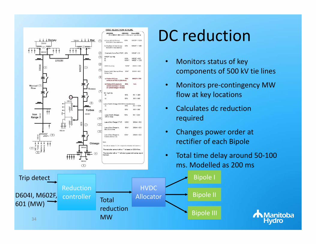
DC reduction
34
Reduction controller
HVDC Allocator
Bipole I
Bipole II
Bipole III
Trip detect
D604I, M602F, 601 (MW) Total
reduction MW
• Monitors status of key components of 500 kV tie lines
• Monitors pre‐contingency MW flow at key locations
• Calculates dc reduction required
• Changes power order at rectifier of each Bipole
• Total time delay around 50‐100 ms. Modelled as 200 ms

Project Scope ‐ Converter Stations
• Total of 20 converter transformers including spare units
• Controlled switching for energizing two parallel converter transformers (3‐phase 5‐limb): Pre‐insertion resistors at Rectifier and Point‐on‐Wave (POW) controllers at Inverter (world first!).
• Both POW and PIR can meet the requirements of mitigating transient inrush (typically less than 0.1pu, 1.5 kA base)
• Controlled switching reduced inrush current such that they could be released for operation in 2 minutes rather than 10 minutes.
35

Field Commissioning & ResultsRiel CS Operation: Optimal Scenario
36
Inrush current: 0.023, 0.02 & ‐0.018
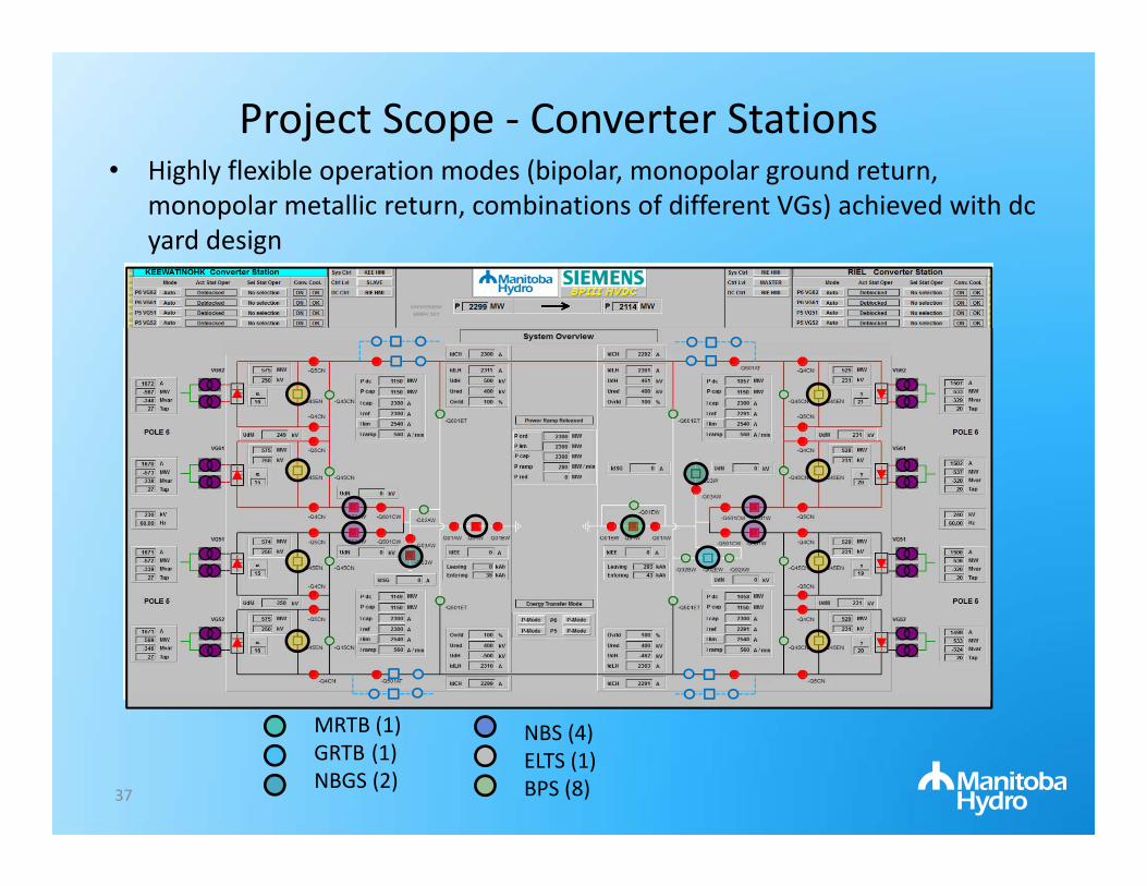
Project Scope ‐ Converter Stations • Highly flexible operation modes (bipolar, monopolar ground return,
monopolar metallic return, combinations of different VGs) achieved with dc yard design
MRTB (1)GRTB (1)NBGS (2)
NBS (4)ELTS (1)BPS (8)37
Project Scope ‐ Converter Stations
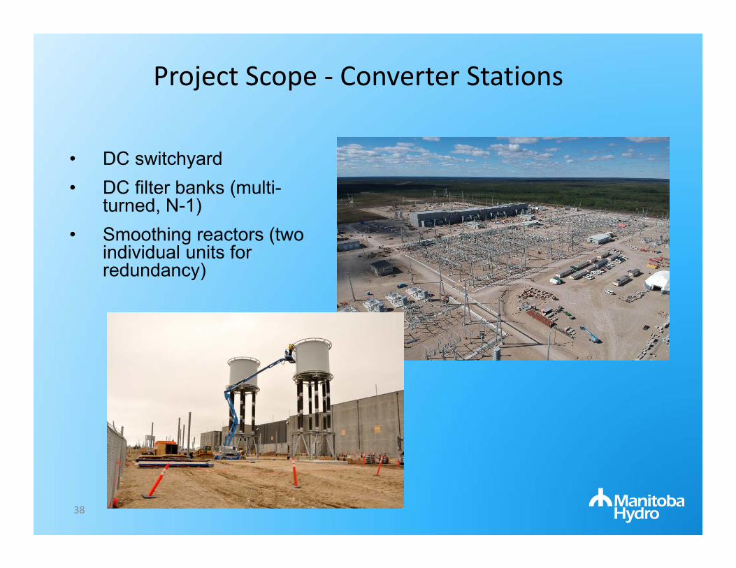
• DC switchyard• DC filter banks (multi-
turned, N-1)• Smoothing reactors (two
individual units for redundancy)
38

Project Scope ‐ Converter Stations
• 230 kV Air Insulated Switchyard (AIS)• New 230 kV bays & apparatus at KCS• Expansion of 230kV yard at RCS• Four AC filter banks at each station
(with controlled switching)
39
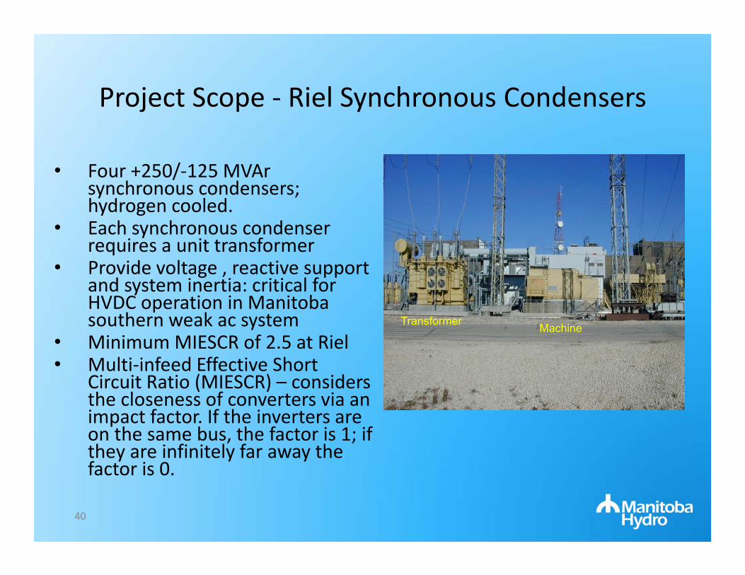
• Four +250/‐125 MVAr synchronous condensers; hydrogen cooled.
• Each synchronous condenser requires a unit transformer
• Provide voltage , reactive support and system inertia: critical for HVDC operation in Manitoba southern weak ac system
• Minimum MIESCR of 2.5 at Riel• Multi‐infeed Effective Short
Circuit Ratio (MIESCR) – considers the closeness of converters via an impact factor. If the inverters are on the same bus, the factor is 1; if they are infinitely far away the factor is 0.
MachineTransformer
Project Scope ‐ Riel Synchronous Condensers
40

Project Scope – HVdc Line
• 1388km, 500KV overhead
• Self‐supporting and guyed towers
• Base reliability level of 150 year return period for weather loads and increased to 500 year return design at some sections
• Anti‐cascading towers (every 5‐10 km)
41

Project Scope – HVdc Line
• 3‐bundle Configuration vs. 2‐bundle of existing Bipole I&II lines
• Conductor surface gradient less than 23kV/cm.
• Bipole II is 28 kV/cm. Reduced noise, corona loss and hopefully reduced risk of anomalous (pseudo‐random fair weather on negative pole) flashovers.
• OPGW for Lightning protection and communication; 4 repeater stations
42

Project Scope – AC System Upgrades
• Five new 230kV ac lines (north) and sectionalization of one 230kV ac line in the south
• Upgrades of two existing ac stations for line terminations
• Breaker upgrades at various stations due to fault level increases
43

BPIII Replica C&P HIL Testing
44
Bipole III C & P Replica
LIMESTONE1260MW
Bipole IIBipole I Bipole III
KEEWATINOHK
DORSEY RIEL
HENDAYRADISSON
LONG SPRUCE980MW
KETTLE1224MW
ACF
ACF
ACF
ACF
ACF
Reduced MH Southern AC System
ACF
SC
SC SC
G
G
G
G
G
FORBES
CHISAGO
2
ExistingReduced AC System
3
3 12 2
12
10
10
6 3 4
real‐timesimulation
Model Improvementso In‐house Bipole I&II modelo Freq‐Dependent TLineo Transformer saturation & OLTCo 55 µs time‐step; 6 racksMH SPS & supplementary controlso HVDC reduction allocator, 500 kV SPTRo Custom SC exciter & JVCMH & US ac dynamic equivalent
RTDS (PB5)
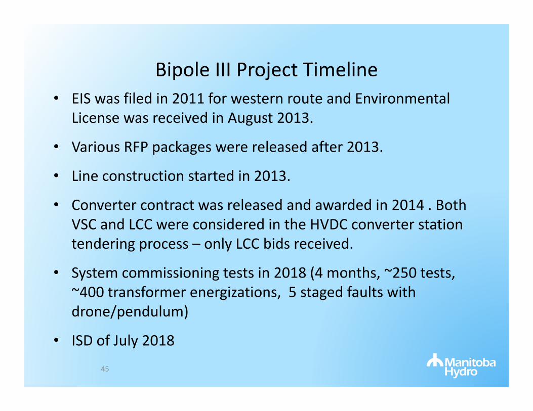
Bipole III Project Timeline• EIS was filed in 2011 for western route and Environmental
License was received in August 2013.
• Various RFP packages were released after 2013.
• Line construction started in 2013.
• Converter contract was released and awarded in 2014 . Both VSC and LCC were considered in the HVDC converter station tendering process – only LCC bids received.
• System commissioning tests in 2018 (4 months, ~250 tests, ~400 transformer energizations, 5 staged faults with drone/pendulum)
• ISD of July 2018
45

Bipole III Future
46
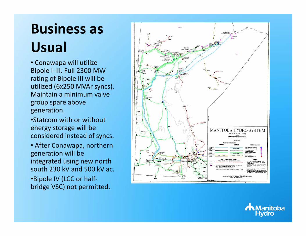
Business as Usual• Conawapa will utilize Bipole I‐III. Full 2300 MW rating of Bipole III will be utilized (6x250 MVAr syncs). Maintain a minimum valve group spare above generation.•Statcom with or without energy storage will be considered instead of syncs.• After Conawapa, northern generation will be integrated using new north south 230 kV and 500 kV ac. •Bipole IV (LCC or half‐bridge VSC) not permitted.

With BPIII VSC taps (full bridge)• Stage 1 – Integrate 680 MW
Burntwood River; 700 MW VSC near Thompson plus new collector system (370 km)
• Stage 2 – Integrate 500 MW of Upper Nelson generation; 500 MW parallel VSC tap at Thompson and 500 MW tap at Brandon
Limestone
Kettle
Jenpeg
Selkirk
Brandon
Grand Rapids
Thompson
Dorsey
Riel
Keewatinohk

With BPIII VSC taps
• Stage 3 – Integrate 1130 MW Conawapa plant; 700 MW parallel VSC tap at Brandon; Conawapaconnects to Riel via east side Bipole. Salvage and relocate DC lines. End up with a 1200 VSC point to point link to Brandon and a 2000 MW LCC link between NCS and Winnipeg, which creates three north‐south corridors.
Limestone
Kettle
Jenpeg
Selkirk
Brandon
Grand Rapids
Thompson
Dorsey
Riel
Keewatinohk

Summary• Bipole III has a long history!• Bipole III is a large investment ($B) by Manitoba Hydro to
address the lack of redundancy in the HVdc system and load serving deficiency under catastrophic HVdc contingencies
• The in‐service of Bipole III reliability project significantly enhances our system reliability and resilience.
• BP3 offers adequate HVdc transmission spare to facilitate & optimize BPI/II refurbishment .
• Provides additional HVdc capacity for future renewable energy development in northern Manitoba.
50

Video
51

Questions?