bjve family - de.stoneagetools.com · bjve family self rotary swivels user manual pl 677 rev a...
TRANSCRIPT

BJVE FAMILY SELF ROTARY SWIVELS
USER MANUAL
PL 677 REV A(07/2019)
BJVE-P1610K (700 bar)
BJVE-M2422K (1500 bar)
BJVE-P1215K (1000 bar)
BJVE-MP1222K (1500 bar)
2 866-795-1586 • WWW.STONEAGETOOLS.COM
TABLE OF CONTENTS
MANUFACTURER’S INFORMATION . . . . . . . . . . . . . . . . . . . . . . . . . . . . . . . . . . . . . . . . . . . . . . . . . . . . . . . . . . . 3
SPECIFICATIONS FOR ALL MODELS . . . . . . . . . . . . . . . . . . . . . . . . . . . . . . . . . . . . . . . . . . . . . . . . . . . . . 3KEY FEATURES FOR ALL MODELS . . . . . . . . . . . . . . . . . . . . . . . . . . . . . . . . . . . . . . . . . . . . . . . . . . . . . . . 3TOOL DESCRIPTION AND INTENDED USE . . . . . . . . . . . . . . . . . . . . . . . . . . . . . . . . . . . . . . . . . . . . . . . 3
WARNING AND SAFETY INSTRUCTIONS . . . . . . . . . . . . . . . . . . . . . . . . . . . . . . . . . . . . . . . . . . . . . . . . . . . . . 4
BJVE MODELS AND OPERATION . . . . . . . . . . . . . . . . . . . . . . . . . . . . . . . . . . . . . . . . . . . . . . . . . . . . . . . . . . . . . . 5
VISCOUS FLUID TYPE INFORMATION . . . . . . . . . . . . . . . . . . . . . . . . . . . . . . . . . . . . . . . . . . . . . . . . . . . . 5HEAD OPTION INFORMATION . . . . . . . . . . . . . . . . . . . . . . . . . . . . . . . . . . . . . . . . . . . . . . . . . . . . . . . . . . . . 6JETTING INFORMATION . . . . . . . . . . . . . . . . . . . . . . . . . . . . . . . . . . . . . . . . . . . . . . . . . . . . . . . . . . . . . . . . . . 7OPERATION . . . . . . . . . . . . . . . . . . . . . . . . . . . . . . . . . . . . . . . . . . . . . . . . . . . . . . . . . . . . . . . . . . . . . . . . . . . . . . . 8TROUBLESHOOTING . . . . . . . . . . . . . . . . . . . . . . . . . . . . . . . . . . . . . . . . . . . . . . . . . . . . . . . . . . . . . . . . . . . . . 9
BJVE MAINTENANCE . . . . . . . . . . . . . . . . . . . . . . . . . . . . . . . . . . . . . . . . . . . . . . . . . . . . . . . . . . . . . . . . . . . . . . . . . . 10
TOOL SERVICE INFORMATION . . . . . . . . . . . . . . . . . . . . . . . . . . . . . . . . . . . . . . . . . . . . . . . . . . . . . . . . . . . 10HIGH PRESSURE SEAL REPLACEMENT . . . . . . . . . . . . . . . . . . . . . . . . . . . . . . . . . . . . . . . . . . . . . . . . . . 11DISASSEMBLY . . . . . . . . . . . . . . . . . . . . . . . . . . . . . . . . . . . . . . . . . . . . . . . . . . . . . . . . . . . . . . . . . . . . . . . . . . . . 12ASSEMBLY . . . . . . . . . . . . . . . . . . . . . . . . . . . . . . . . . . . . . . . . . . . . . . . . . . . . . . . . . . . . . . . . . . . . . . . . . . . . . . . . 15PART NAMES/NUMBERS . . . . . . . . . . . . . . . . . . . . . . . . . . . . . . . . . . . . . . . . . . . . . . . . . . . . . . . . . . . . . . . . . 20SERVICE KITS . . . . . . . . . . . . . . . . . . . . . . . . . . . . . . . . . . . . . . . . . . . . . . . . . . . . . . . . . . . . . . . . . . . . . . . . . . . . . 20
BJVE ACCESSORIES . . . . . . . . . . . . . . . . . . . . . . . . . . . . . . . . . . . . . . . . . . . . . . . . . . . . . . . . . . . . . . . . . . . . . . . . . . . 21
TERMS AND CONDITIONS AND WARRANTY . . . . . . . . . . . . . . . . . . . . . . . . . . . . . . . . . . . . . . . . . . . . . . . . . 27
This manual must be used in accordance with all applicable national laws. The manual shall be regarded as a part of the machine and shall be kept for reference until the final dismantling of the machine, as defined by
applicable national law(s). Updated manuals can be downloaded at: https://www.stoneagetools.com/manuals

3866-795-1586 • WWW.STONEAGETOOLS.COM
MANUFACTURER’S INFORMATION
StoneAge Inc.466 S. Skylane DriveDurango, CO 81303, USAPhone: 970-259-2869Toll Free: 866-795-1586www.stoneagetools.com
StoneAge EuropeUnit 3 Crucible Business Park Woodbury Lane, Norton, Worcester, Worcestershire, WR5 2DQ United KingdomPhone: +44 (0) 1684 892065
DESCRIPTION OF EQUIPMENT AND INTENDED USE
The BJVE tool line is our most versatile line of pipe cleaning tools. They are designed for the widest range of pipe diameters, pressures, flows, and configurations. A variety of head options allows for pulling ring connections, customized porting and multiple jetting options. Different viscous fluid options allow operators the ability to change the speed of rotation for hard or easy applications. This tool has a wide range of centralizer, backout preventers, and automated delivery systems. BJVE tools can also be used in tank and stack cleaning applications.
KEY FEATURES
• Easy Field Service- High Pressure Seal, Carbide, and Shaft Seat can all be replaced in under 3 minutes with only a hex key and wrench.
• Multiple jetting configurations- Same tool can be re-jetted to match a wide variety of cleaning applications. Great for when you need more pulling force or forward hitting power.
• Streamlined body design- helps prevent tool from catching inside of pipe.
• Patented speed control- has been optimized to deliver consistent rotation speed over broad speed and torque window and temperature range – which means better cleaning under adverse conditions.
BJVE Model Specifications
MODEL BJVE-P16 BJVE-P12 BJVE-M24 BJVE-MP12
Units US Metric US Metric US Metric US Metric
Pressure Range 2-10k psi 140-700 bar 2k-15k psi 140-1000
bar 2k-22k psi 140-1500 bar 2k-22k psi 140-1500
bar
Flow Range 20-200 gpm
76-757 lpm
12-100 gpm
45-380 lpm
12-100 gpm
45-380 lpm
12-100 gpm
45-380 lpm
Swivel Diameter 3 in. 76 mm 3 in. 76 mm 3 in. 76 mm 3 in. 76 mm
Swivel Length 8.8 in. 224 mm 8.8 in. 224 mm 8.8 in. 224 mm 8.8 in. 224 mm
Swivel Weight 8.5 lb 4 kgs 8.5 lbs 4 kgs 8.5 lbs 4 kgs 8.5 lbs 4 kgs
Head Weight 3.3 lbs 1.5 kgs 3.3 lbs 1.5 kgs 3.3 lbs 1.5 kgs 3.3 lbs 1.5 kgs
MaximumWater Temp.
160 ºF 70 ºC 160 ºF 70 ºC 160 ºF 70 ºC 160 ºF 70 ºC
Flow Coefficient 7.5 Cv 4.6 Cv 4.6 Cv 4.6 Cv
Inlet Connection 1 NPT 3/4 NPT M24 3/4 MP
Port Size1/4 NPT (P4)1/2 NPT (P8)
1/4 NPT (P4)1/2 NPT (P8)
1/4 NPT (P4)G12
1/4 NPT (P4)G12
Nozzle TypesAP4, APF4, OC8-P4,
OC8-P12AP4, APF4, OC8-P4,
OC8-P12AP4, APF4 AP4, APF4
Port PlugGP 025-P4SSGP 025-P8SS
GP 025-P4SSGP 025-P8SS
GP 025-P4SSSA 058-G12
GP 025-P4SSSA 058-G12

4 866-795-1586 • WWW.STONEAGETOOLS.COM
WARNING AND SAFETY INSTRUCTIONS
WARNING BJVE Models can turn around in large pipes and come back at the operator at a high rate of speed. If cleaning larger pipes, a rigid “stinger” should be used between the hose and the tool. It is recommended that the rigid length of the tool including hose end is 1-1/2 times the inside diameter of the pipe being cleaned (see below).Make sure there is an operator controlled dump in the system, operated by the person closest to the cleaning job. Flush out the high pressure hoses before connecting the BJVE. It is recommended that the hose be marked a few feet from the end with a piece of tape so the operator knows when to stop when retracting the tool. Position the tool in the pipe opening. Close the dump and slowly bring up to pressure the first time to make sure no nozzles are plugged and the jet thrust is correct. The BJVE should begin to slowly rotate. Once operating pressure is reached, feed the tool into the pipe to begin the cleaning job. Allow the jets time to do their work by feeding the hose out at a controlled rate. The StoneAge ABX-500 Hose Control Device can be used to achieve consistent feed rates for pipe cleaning. When the work is complete and the tool is disconnected from the hose, blow out all water to prolong the life of the tool. A small amount of lubricant can be blown into the tool as well as an added measure to maximize tool life.
It is strongly recommended to use a backout prevention device. Please see the “Accessories” section of this manual for a list of backout preventers available through StoneAge Tools.
DANGEROperations with this equipment can be potentially hazardous. Caution must be exercised prior to and during machine and water jet tool use. Please read and follow all of these instructions, in addition to
the guidelines in the WJTA Recommended Practices handbook, available online at www.wjta.org.
Deviating from safety instructions and recommended practices can lead to severe injury and/or death.
Rigid Stinger
IMPROPER USE:BJVE will turn around in
large diameter pipeVERY DANGEROUS!
PROPER USE:BJVE with rigid “stinger”
to prevent turnaround.
1-1/2 times pipe ID
Pipe ID
Rigid Stinger
5866-795-1586 • WWW.STONEAGETOOLS.COM
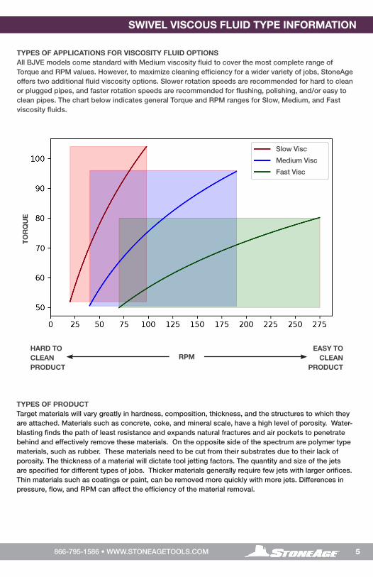
TYPES OF APPLICATIONS FOR VISCOSITY FLUID OPTIONSAll BJVE models come standard with Medium viscosity fluid to cover the most complete range of Torque and RPM values. However, to maximize cleaning efficiency for a wider variety of jobs, StoneAge offers two additional fluid viscosity options. Slower rotation speeds are recommended for hard to clean or plugged pipes, and faster rotation speeds are recommended for flushing, polishing, and/or easy to clean pipes. The chart below indicates general Torque and RPM ranges for Slow, Medium, and Fast viscosity fluids.
SWIVEL VISCOUS FLUID TYPE INFORMATION
HARD TO CLEAN PRODUCT
EASY TO CLEAN
PRODUCTRPM
TO
RQ
UE
TYPES OF PRODUCTTarget materials will vary greatly in hardness, composition, thickness, and the structures to which they are attached. Materials such as concrete, coke, and mineral scale, have a high level of porosity. Water-blasting finds the path of least resistance and expands natural fractures and air pockets to penetrate behind and effectively remove these materials. On the opposite side of the spectrum are polymer type materials, such as rubber. These materials need to be cut from their substrates due to their lack of porosity. The thickness of a material will dictate tool jetting factors. The quantity and size of the jets are specified for different types of jobs. Thicker materials generally require few jets with larger orifices. Thin materials such as coatings or paint, can be removed more quickly with more jets. Differences in pressure, flow, and RPM can affect the efficiency of the material removal.
Slow Visc
Medium Visc
Fast Visc

6 866-795-1586 • WWW.STONEAGETOOLS.COM
HEAD OPTION INFORMATION
BJVE HEAD OPTIONS PER SWIVEL
HEAD BJVE SWIVEL TYPE
SIZE DESCRIPTION PART NUMBERM24
(15K, 22K)MP12 (22K)
P12 (10K,15K)
P16 (10K)
3.0”
(76
mm
) Ø H
EA
DS (6) ¼ NPT PORTS
AP4-XXX NOZZLES
BJ 144-P4-6-R12 √ √ √ √
BJ 144-P4-6-R20 √ √ √ √
BJ 144-P4-6-R35 √ √ √ √
BJ 144-P4-6-R60 √ √ √ √
(7) ¼ NPT PORTS
AP4-XXX NOZZLES
BJ 144-P4-7-R12 √ √ √ √
BJ 144-P4-7-R20 √ √ √ √
BJ 144-P4-7-R35 √ √ √ √
BJ 144-P4-7-R60 √ √ √ √
3.5”
(89
mm
) Ø H
EA
DS
(6) ¾-16 NF PORTS
AP4-XXX NOZZLES
MUST BE USED WITH G12-P4 EXTENSION
ARMS OR G12 PLUGS
BJ 145-G12-R12 √ √ — —
BJ 145-G12-R20 √ √ — —
BJ 145-G12-R35 √ √ — —
BJ 145-G12-R60 √ √ — —
(6) 1/2 NPT PORTS
AP4-XXX NOZZLES
MUST BE USED WITH P8-P4 EXTENSION
ARMS OR P8 PLUGS
BJVE 145-P8-R12 — — √ √
BJVE 145-P8-R20 — — √ √
BJVE 145-P8-R35 — — √ √
BJVE 145-P8-R60 — — √ √
135º 45º
45º
90º
90º
135º
135º 45º
15º
45º
90º
90º
135º
135º
45º
45º
90º
90º
135º
BJ 145-G12-6-Rxx or
BJVE 145-P8-6-Rxx 6-PORT2 @ 45º 2 @ 90º 2 @ 135º
BJ 144-P4-7-Rxx 7-PORT1 @ 15º2 @ 45º 2 @ 90º 2 @ 135º
BJ 144-P4-6-Rxx6-PORT2 @ 45º 2 @ 90º 2 @ 135º
HEAD OPTIONS PER SWIVEL TYPE: There are four standard head configurations, with custom heads available on request. The correct head specification is based on the pressure and flow of the pump and the required port size. Heads with P8 or G12 ports require extension arms or plugs.
7866-795-1586 • WWW.STONEAGETOOLS.COM
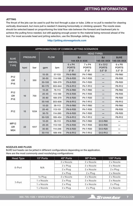
JETTINGThe thrust of the jets can be used to pull the tool through a pipe or tube. Little or no pull is needed for cleaning vertically downward, but more pull is needed if cleaning horizontally or climbing upward. The nozzle sizes should be selected based on proportioning the total flow rate between the forward and backward jets to achieve the pulling force needed, but still applying enough power to the material being removed ahead of the tool. For most accurate head and jetting selection, use the StoneAge Jetting App.
http://jetting.stoneagetools.com
APPROXIMATIONS OF COMMON JETTING SCENARIOS
BJVE SWIVEL
TYPE
PRESSURE FLOW
HEAD TYPES
BJ144-XX-X-XXX
BJ145-XX-XXX
BJVE 145-XX-XXX
kpsi bar gpm lpm6 x P4 PORTS
3” Ø
7 x P4 PORTS
3” Ø
6 x G12 PORTS 3.5” Ø
6 x P8 PORTS 3.5” Ø
P12 ORP16
5 350
15-35 57-133 P4-6-R60 P4-7-R60 — P8-R60
30-50 114-189 P4-6-R35 P4-7-R35 — P8-R35
50-100 189-379 P4-6-R20 P4-7-R20 — P8-R20
80-170 303-644 P4-6-R12 P4-7-R12 — P8-R12
P12 ORP16
10 700
15-25 76-113 P4-6-R60 P4-7-R60 — P8-R60
20-45 113-189 P4-6-R35 P4-7-R35 — P8-R35
35-80 189-379 P4-6-R20 P4-7-R20 — P8-R20
55-140 303-606 P4-6-R12 P4-7-R12 — P8-R12
P12 15 1034
10-20 38-113 P4-6-R60 P4-7-R60 — P8-R60
20-40 113-151 P4-6-R35 P4-7-R35 — P8-R35
30-70 114-265 P4-6-R20 P4-7-R20 — P8-R20
50-120 189-454 P4-6-R12 P4-7-R12 — P8-R12
MP12ORM24
22 1517
10-20 38-113 P4-6-R60 P4-7-R60 G12-R60 —20-35 113-133 P4-6-R35 P4-7-R35 G12-R35 —30-65 114-246 P4-6-R20 P4-7-R20 G12-R20 —50-110 189-416 P4-6-R12 P4-7-R12 G12-R12 —
JETTING INFORMATION
NOZZLES AND PLUGSBJVE tool heads can be jetted in different configurations depending on the application. Here are the most commonly used nozzle/plug configurations:
Head Type 15º Ports 45º Ports 90º Ports 135º Ports
6-Port N/A
2 x Nozzle 2 x Nozzle 2 x Nozzle
2 x Plug 2 x Nozzle 2 x Nozzle
2 x Plug 2 x Nozzle 2 x Plug
2 x Plug 2 x Plug 2 x Nozzle
7-Port
1x Plug 2 x Nozzle 2 x Nozzle 2 x Nozzle
1 x Nozzle 2 x Plug 2 x Nozzle 2 x Nozzle
1 x Nozzle 2 x Plug 2 x Nozzle 2 x Plug
1 x Nozzle 2 x Plug 2 x Plug 2 x Nozzle
8 866-795-1586 • WWW.STONEAGETOOLS.COM
OPERATION
OPERATION: • Make sure there is an operator controlled dump in the system, operated by the person closest to
the cleaning job.
• Flush out the high pressure hoses before connecting BJVE to hose end or stinger to eliminate debris.
• It is recommended that the hose be marked a few feet from the end with a piece of tape so the operator knows when to stop on the way back out.
• When cleaning a pipe, a stinger is recommended; a stinger is a rigid piece of pipe or tubing used between the end of the hose and the nozzle. It is typically 2 feet in length, and is primarily a safety device for hand flex lancing. This is illustrated on the “Warning and Safety Instructions” page of this manual.
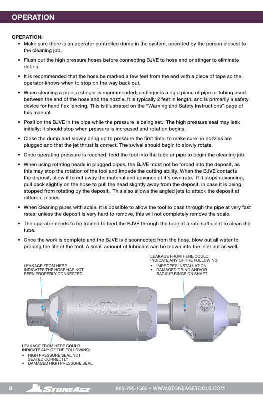
• Position the BJVE in the pipe while the pressure is being set. The high pressure seal may leak initially; it should stop when pressure is increased and rotation begins.
• Close the dump and slowly bring up to pressure the first time, to make sure no nozzles are plugged and that the jet thrust is correct. The swivel should begin to slowly rotate.
• Once operating pressure is reached, feed the tool into the tube or pipe to begin the cleaning job.
• When using rotating heads in plugged pipes, the BJVE must not be forced into the deposit, as this may stop the rotation of the tool and impede the cutting ability. When the BJVE contacts the deposit, allow it to cut away the material and advance at it’s own rate. If it stops advancing, pull back slightly on the hose to pull the head slightly away from the deposit, in case it is being stopped from rotating by the deposit. This also allows the angled jets to attack the deposit at different places.
• When cleaning pipes with scale, it is possible to allow the tool to pass through the pipe at very fast rates; unless the deposit is very hard to remove, this will not completely remove the scale.
• The operator needs to be trained to feed the BJVE through the tube at a rate sufficient to clean the tube.
• Once the work is complete and the BJVE is disconnected from the hose, blow out all water to prolong the life of the tool. A small amount of lubricant can be blown into the inlet nut as well.
LEAKAGE FROM HERE COULD INDICATE ANY OF THE FOLLOWING; • IMPROPER INSTALLATION • DAMAGED ORING AND/OR
BACKUP RINGS ON SHAFT
LEAKAGE FROM HERE COULD INDICATE ANY OF THE FOLLOWING; • HIGH PRESSURE SEAL NOT
SEATED CORRECTLY• DAMAGED HIGH PRESSURE SEAL
LEAKAGE FROM HERE INDICATES THE HOSE HAS NOT BEEN PROPERLY CONNECTED

9866-795-1586 • WWW.STONEAGETOOLS.COM
OPERATION TROUBLESHOOTING
TROUBLESHOOTING
HIGH-PRESSURE SEALS LEAK
-The high pressure seal may leak initially at lower pressures, but should pop closed as pressure is increased.
-A continuous leak at operating pressure from the weep holes indicates the need to replace the HP Seal and Seat.
-HP Seals wearing out too quickly can be an indication that the cartridge bore is worn, the HP Seat in the seal assembly is installed upside-down, or the tool is over spinning.
-Over spinning may be caused by a lack of lubricating fluid, water in the fluid chamber (replace shaft seals), or too much jet torque. Refilling the lubricating fluid during complete overhaul or in cases of contamination is important for proper speed control.
-Only use StoneAge recommended lubricating fluids.
SEALS WEAR OUT TOO QUICKLY
-The tool must be disassembled and inspected.
-Check the carbide seat for correct installation.
-Check the carbide seat for any chips or erosion marks on it.
-The bore on the Cartridge where the Carbide Seat sits should be inspected. If it is worn to greater than .753ӯ on the P16 model or .628ӯ on the other models, the Cartridge will need to be replaced.
HEAD WILL NOT ROTATE
-First try rotating head by hand and see if it feels rough or gritty to turn.
-If the tool does not rotate, it must be disassembled and serviced.
-If the head starts to rotate but slows down and stops as pressure is increased, it is an indication that the bearings need to be replaced.
-If the tool feels okay, check to see if any nozzles are plugged; even if a nozzle is only partially blocked it can keep the head from rotating. Nozzles must be removed from the head to properly clean them.
-Check the nozzle sizes and head offset to make sure they are correctly specified. This can be done online at; http://jetting.stoneagetools.com
HEAD SPINS TOO FAST
-Check the nozzle sizes and head offset to make sure they are correctly specified. This can be done online at; http://jetting.stoneagetools.com
-A significant increase in rotation speed can also mean the speed control mechanism in the tool has lost functionality. This can be a result of fluid loss or fluid contamination. Operation of the tool in this state can cause damage to other components and accelerated wear of the high pressure seal. If this occurs, the first step is to flush the tool with new viscous fluid as shown in the “Lubricant Replacement” instructions in this manual.

10 866-795-1586 • WWW.STONEAGETOOLS.COM
TOOL SERVICE INFORMATION
TOOL SERVICEProduct training and proper tools are required to service this nozzle. If you are uncomfortable performing the service, send in or bring the tool to your authorized dealer. StoneAge provides maintenance videos for the BJVE models online.
https://www.stoneagetools.com/bjv
The use of a bench vice and an arbor press is recommended. Take care throughout the entire procedure to keep the internals clean and free from grit, lint, and contamination. Failure to do so could result in premature failure after service.
LIST OF TOOLS:
• Bench Vise (recommended)
• Arbor Press (recommended)
• BJVE 612 Tool Kit:WGR 186 HP Seal PullerBJVE 180 Installation Press Tool
• Automotive Sliding Wrench(Crescent® C718 or equivalent)
• Large Adjustable End Wrench
• Medium size flat-head screw driver
• T-Handle Hex Allen, 8mm (10mm for P16)
• 90º Pick
• 1 Inch Socket
LIST OF MATERIALS:
• Clean lint free rags or shop towels
• BJ 048- (F, M, or S) Viscous Fluid
• Anti-Seize - Swagelok® Blue Goop®
StoneAge PN (GP 043)
• Grease - Chevron Multifak® EP1 StoneAge PN (GP 049)
Multifak® is a registered trademark of Chevron® Corporation.Blue Goop® is a registered trademark of Swagelok® Company
BJVE 612 TOOL KIT (INCLUDES)
BJVE 180Installation Press Tube
WGR 186 HP Seal Puller

11866-795-1586 • WWW.STONEAGETOOLS.COM
HIGH PRESSURE SEAL REPLACEMENT
TO REPLACE THE HIGH PRESSURE SEAL:
1. Clamp the flats of the Inlet Nut Cartridge down in a bench vise with the Shaft end facing up.
2. Grab the flats on the Inlet Nut with a large Adjustable End Wrench and rotate the Body off in a counter-clockwise direction.
DO NOT USE THE FLATS ON THE BODY TO REMOVE AS IT WILL SEPARATE THE BODY FROM THE INLET NUT.
3. Remove the Carbide Seat and High Pressure Seal from inside the Inlet Nut Cartridge with the WGR 186 Seal Puller tool. It’s possible that the Carbide might still be adhered to the inside of the Inlet Nut.
4. Inspect the Carbide Seat and Seal surface for chips or erosion and replace if damaged.
5. Apply grease to the O-Ring on a new High Pressure Seal and press it into the Inlet Cartridge with the O-Ring Side down. Press it in until the top of the Seal is even with the bottom of the chamfer.
6. Apply grease to the flat face of the Carbide Seat and install with this flat face against the top of the H.P. Seal.
7. Apply Anti-seize to the threads of the Inlet Nut Cartridge.
8. Screw the Body Assembly back onto the Inlet Nut Cartridge and tighten the Body by the flats of the Inlet Nut with a Large Adjustable End wrench.
BJVE 015-PxInlet Cartridge
BJVE 003Body
SHAFT END
Figure 1: For Steps 1-2 and 8 Figure 2: For Step 3
Figure 3: For Step 5 Figure 4: For Steps 6-7
O-Ring
BJVE 012-TOH.P. Seal
Bottom of chamfer
GREASE
BJVE 012-TOH.P. Seal
MJ 011-CCarbide Seat
WGR 186 HP Seal Puller
BJ 211 Brass Seat(P16 ONLY)
BJVE 212-TO H.P. Seal & O-Ring(P16 ONLY)
Chamfered face of carbide seat
Flat face of carbide seat
GREASE
ANTI-SEIZE
INSPECT

12 866-795-1586 • WWW.STONEAGETOOLS.COM
DISASSEMBLY
DISASSEMBLY
1. Remove the Head by clamping it in a vise with the Inlet Nut facing up.
2. Use an adjustable wrench on the flats of the Shaft to loosen the Swivel from the Head. Unscrew the body from the head by hand.
Figure 7: For Steps 3-4
BJV or BJVEHead
BJVE 001 Shaft
BJVE 002Inlet Nut
Adjustable End Wrench
Figure 6: For Steps 1-2
BJVE 015-PxInlet Cartridge
BJVE 003Body
5. Remove the Carbide Seat and High Pressure Seal and from inside the Inlet Nut Cartridge with the WGR 186 Seal Puller tool.
BJVE 002Inlet Nut
Figure 8: For Step 6
Figure 7: For Step 5
INSPECT
MJ 011-CCarbide Seat
BJ 211 Brass Seat(P16 ONLY)
BJVE 002Inlet Nut
BJVE 003Body
3. Clamp the flats of the Inlet Nut Cartridge down in a bench vise with the Shaft end facing up.
4. Use an Automotive Sliding Wrench on the flats of the Inlet Nut and rotate the Body off of the Inlet Nut Cartridge in a counter-clockwise direction. Use caution not to lose the Carbide Seat on the Shaft.
6. If the Carbide Seat is not on top of the High Pressure Seal after the Body is removed, pop it out from inside the Inlet Nut. Inspect the Carbide Seat and seal surface for chips or erosion and replace if damaged.
BJVE 012-TOH.P. Seal
MJ 011-CCarbide Seat
WGR 186 HP Seal Puller
BJ 211 Brass Seat(P16 ONLY)
BJVE 212-TO H.P. Seal & O-Ring(P16 ONLY)
DO NOT USE THE FLATS ON THE BODY.

13866-795-1586 • WWW.STONEAGETOOLS.COM
Figure 9: For Step 7
NOTICE DO NOT clamp the Body down in vise too tightly. It is extremely important not to ovalize the Body. This
can cause the shaft to gall against the Body and premature failure of the tool.
BJVE 003Body
8mm Hex(10mm for P16 models)
BJVE 016-OSeat Face
7. Keep the Shaft from rotating with an Adjustable End Wrench. Remove the Seat Face Assembly with a Hex wrench.
All models are 8mm except P16 which is 10mm.
BJVE 001 Shaft
8. Remove the Inlet Nut Assembly from the Body with an Automotive Sliding Wrench.
BJVE 003 Body
DISASSEMBLY
9. Remove the Body from the vise and flip it over a tub or an area where the viscous fluid can drain out.
10. The Shaft will slip out of the Body.
Figure 11: For Steps 9-10
Figure 12: For Steps 11-12
11. Use a small 90o pick to remove the Shaft Seal from inside the Body.
12. The Bearing should slide freely and can be removed by hand.
Figure 10: For Step 8
BJVE 003Body
BJVE 003Body
BJVE 006Shaft Seal
BJ 007Bearing
Small 90º Pick
Inlet Nut Subassembly
DO NOT SCRATCH THE INSIDE OF THE BODY.
14 866-795-1586 • WWW.STONEAGETOOLS.COM
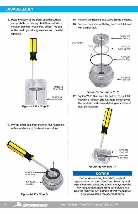
DISASSEMBLY
14. Pry the Shaft Seal from the Inlet Nut Assembly with a medium size flat-head screw driver.
15. Remove the Bearing and Wave Spring by hand.
16. Remove the external O-Ring from the Inlet Nut with a small pick.
BJVE 010Shaft Seal
WHR 006Shaft Seal
BJVE 002Inlet Nut
BJVE 002Inlet Nut
Figure 14: For Step 14
Figure 15: For Steps 15-16
Figure 16: For Step 17
BJVE 008O-Ring
BJVE 002Inlet Nut
WHR 014Wave Spring
SC212 007Bearing
17. Pry the WHR Seal from the bottom of the Inlet Nut with a medium size flat-head screw driver. This seal will be destroyed during removal and must be replaced.
NOTICEBefore Assembling the BJVE, wash all
appropriate parts in solvent and blow dry and wipe clean with a lint free towel. Always use the
new replacement parts from our service kits. See the “Service Kit” section of this manual for
a list of available replacement parts.
Figure 13: For Step 13
BJVE 003Body
WGR 006Shaft Seal
13. Place the back of the Body on a flat surface and push the remaining Shaft Seal out with a medium size flat-head screw driver. This seal will be destroyed during removal and must be replaced.
90.00DEG175.00DEG
15866-795-1586 • WWW.STONEAGETOOLS.COM
ASSEMBLY
WHR 006Shaft Seal
1¼” (32mm)Socket
Figure 18: For Step 2 Figure 20: For Step 4
BJVE 002Inlet Nut
ASSEMBLY
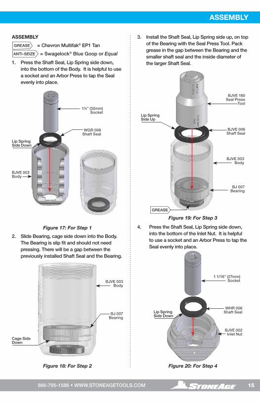
1. Press the Shaft Seal, Lip Spring side down, into the bottom of the Body. It is helpful to use a socket and an Arbor Press to tap the Seal evenly into place.
Lip Spring Side Down
WGR 006Shaft Seal
BJVE 003Body
Figure 17: For Step 1
Lip Spring Side Down
2. Slide Bearing, cage side down into the Body. The Bearing is slip fit and should not need pressing. There will be a gap between the previously installed Shaft Seal and the Bearing.
Cage Side Down
BJ 007Bearing
BJ 007Bearing
BJVE 003Body
3. Install the Shaft Seal, Lip Spring side up, on top of the Bearing with the Seal Press Tool. Pack grease in the gap between the Bearing and the smaller shaft seal and the inside diameter of the larger Shaft Seal.
4. Press the Shaft Seal, Lip Spring side down, into the bottom of the Inlet Nut. It is helpful to use a socket and an Arbor Press to tap the Seal evenly into place.
GREASE
ANTI-SEIZE
= Chevron Multifak® EP1 Tan
= Swagelock® Blue Goop or Equal
BJVE 180Seal Press
Tool
BJVE 006Shaft Seal
Figure 19: For Step 3
Lip Spring Side Up
BJVE 003Body
GREASE
1 1/16” (27mm)Socket
175.00DEG

16 866-795-1586 • WWW.STONEAGETOOLS.COM
ASSEMBLY
5. Install O-Ring around the outside of the threads on the Inlet Nut.
6. Pack the Bearing with grease.
7. Insert the Wave Spring, Bearing, and Shaft Seal into the Inlet Nut. Use the Inlet Nut end of the Press Tool to install the Shaft Seal.
Figure 21: For Steps 5-7
Figure 23: For Steps 9-11
Figure 24: For Step 12Figure 22: For Step8
BJVE 008O-Ring
BJVE 002Inlet Nut
BJVE 001 Shaft
BJ 072O-Ring
BJ 071Backup Ring
WHR 014Wave Spring
SC212 007Bearing
Non directional
BJVE 010Shaft Seal
BJVE 180Seal Press
Tool
8. Install the Backup Ring and O-Ring onto the end of the Shaft.
NOTICENever remove the Retaining Ring or Pistons from the Shaft Assembly.
9. Clean the inside of the body thoroughly with a lint free towel.
10. Put a thin film of grease on all the Shaft surfaces on the Shaft before inserting it into the Body.
11. Apply anti-seize to the threads of the Shaft.
BJVE 003Body
BJVE 001 Shaft
GREASE
GREASE
GREASE
GREASE
ANTI-SEIZE
CLEAN
Lip Spring Side Up
TECH TIP: Wiggling the Shaft a bit will help it slide through the Shaft Seals in the Body.
12. Carefully clamp the flats of the Body on one side of the Vise. The Shaft end needs to be accessible in order to twist it during the Viscous fluid fill.

17866-795-1586 • WWW.STONEAGETOOLS.COM
Figure 28: For Steps 19-21
Figure 25: For Steps 13-14
Figure 26: For Step 15
Figure 27: For Steps 16-18
FS 021-KO-Ring
RPT 031Backup Ring
BJVE 016 Seat Face
ASSEMBLY
GREASE
INSPECT
INSPECT
ANTI-SEIZE
CLEAN
19. Before installing the Seat Face assembly into the Shaft, inspect the Backup Ring, O-Ring, and Seat face surface. Replace any or all damaged parts.
20. Install the Backup Ring on the Seat Face and then the O-Ring.
21. Grease the O-Ring but make sure the Seal Surface is clean before installing into the Shaft.
ANTI-SEIZE
BJVE 003Body
Inlet Nut Subassembly
TECH TIP: The viscosity of the fluid is very thick and can take a while to sink down into the tool. Air bubbles may rise between the Shaft and Body
FILL LINE
13. Fill the Body with Viscous Fluid up to the top taper just below the threads of the Body.
This fluid level height is critical.
14. Keep rotating the Shaft slowly in a Counterclockwise direction to work the visc into the tool.
16. Apply Anti-Seize to the Inlet Nut threads and wipe off any residual lubricants from the seal side.
17. Install the Inlet Nut Assembly slowly by hand onto the Body. Visc will ooze out of the Port. If no viscous fluid comes out, then more needs to be added to the Body. Return to Step 13.
18. Tighten fully with an Automotive Sliding Wrench and reinstall the Port Screw. Leave the assembly in the Vise.
CLEAN
15. Remove the Port Screw that does not have the bushing nut underneath it before installing on the Body. DO NOT remove that Port Plug.
NOTICENever remove the Port Plug with the Bushing.
18 866-795-1586 • WWW.STONEAGETOOLS.COM
BJVE 003Body
8mm Hex(10mm for P16
models)
BJVE 016-OSeat Face
ASSEMBLY
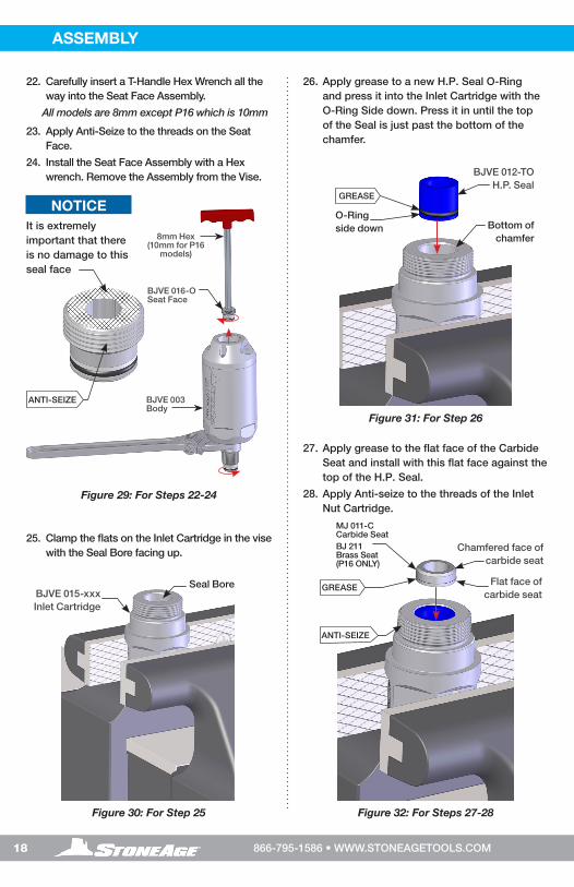
22. Carefully insert a T-Handle Hex Wrench all the way into the Seat Face Assembly.
All models are 8mm except P16 which is 10mm
23. Apply Anti-Seize to the threads on the Seat Face.
24. Install the Seat Face Assembly with a Hex wrench. Remove the Assembly from the Vise.
NOTICEIt is extremely important that there is no damage to this seal face
ANTI-SEIZE
Figure 29: For Steps 22-24
Figure 31: For Step 26
Figure 32: For Steps 27-28Figure 30: For Step 25
25. Clamp the flats on the Inlet Cartridge in the vise with the Seal Bore facing up.
O-Ring side down
BJVE 012-TOH.P. Seal
GREASE
26. Apply grease to a new H.P. Seal O-Ring and press it into the Inlet Cartridge with the O-Ring Side down. Press it in until the top of the Seal is just past the bottom of the chamfer.
27. Apply grease to the flat face of the Carbide Seat and install with this flat face against the top of the H.P. Seal.
28. Apply Anti-seize to the threads of the Inlet Nut Cartridge.
Bottom of chamfer
Seal Bore
ANTI-SEIZE
GREASEBJVE 015-xxxInlet Cartridge
Chamfered face of carbide seat
Flat face of carbide seat
MJ 011-CCarbide SeatBJ 211 Brass Seat(P16 ONLY)
19866-795-1586 • WWW.STONEAGETOOLS.COM
ASSEMBLY
Figure 34: For Steps 30-31
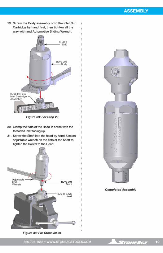
29. Screw the Body assembly onto the Inlet Nut Cartridge by hand first, then tighten all the way with and Automotive Sliding Wrench.
Figure 33: For Step 29
Completed Assembly
BJVE 015-xxxInlet CartridgeAssembly
BJVE 003Body
SHAFT END
BJV or BJVEHead
BJVE 001 Shaft
Adjustable End Wrench
30. Clamp the flats of the Head in a vise with the threaded inlet facing up.
31. Screw the Shaft into the head by hand. Use an adjustable wrench on the flats of the Shaft to tighten the Swivel to the Head.
20 866-795-1586 • WWW.STONEAGETOOLS.COM
KITS PART NUMBER OVERVIEWBJVE 602 SEAL KIT(P12, MP12, M24)
1 BJVE 012-TO HP Seal1 MJ 011-C Carbide Seat1 BJ 071 Backup Ring1 BJ 072 O-Ring
BJVE 603 SEAL KIT(P16 ONLY)
1 BJVE 212-TO HP Seal1 BJ 211 Brass Seat1 BJ 071 Backup Ring1 BJ 072 O-Ring
BJVE 604-XXX SEAL OVERHAUL KIT (P12, MP12, M24)
1 BJVE 012-TO HP Seal1 MJ 011-C Carbide Seat1 BJ 071 Backup Ring1 BJ 072 O-Ring1 BJVE 016-O Shaft Seat1 BJVE 015-XXX Inlet Nut Cartridge
BJVE 605 SEAL OVERHAUL KIT(P16 ONLY)
1 BJVE 212-TO HP Seal1 BJ 211 Brass Seat1 BJ 071 Backup Ring1 BJ 072 O-Ring1 BJVE 016-HF-O High Flow Shaft Seat1 BJVE 015-P16 Inlet Nut Cartridge
BJVE 610 SWIVEL OVERHAUL KIT (ALL MODELS)
1 BJ 007 Front Bearing1 SC212 007 Rear Bearing1 WGR 006 Front-Outer Shaft Seal1 BJVE 006 Front-Inner Shaft Seal1 BJVE 010 Rear-Inner Shaft Seal1 WHR 006 Rear-Outer Shaft Seal1 BJ 008 O-Ring, Inlet Nut2 BJVE 026 Port Plugs1 WHR 014 Wave Spring1 BJ 048-M Medium Visc - 6 oz1 GP 043 Blue Goop 2 oz1 GP 049.1 GP 049.1 Syringe, .68oz1 GP 049.2 Cap, Syringe, Lock Cap
BJVE 612 TOOL KIT(ALL MODELS)
1 WGR 186 HP Seal Puller1 BJVE 180 Installation Press Tool
MAINTENANCE KITS
WHR 014Wave
Spring
SC212 007Bearing
BJVE 008O-Ring
WHR 006Shaft Seal WGR 006
Shaft Seal
BJVE 010Shaft Seal
MJ 011-C Carbide Seat
BJ 211 Brass Seat(P16 ONLY) BJ 026
Port Screw
BJVE 012-TO H.P. Seal & O-Ring
BJVE 212-TO H.P. Seal & O-Ring(P16 ONLY)
BJVE 015-XXXXInlet Nut Cartridge
BJVE 016 or BJVE 016-HF-O
Seat Face
BJVE 002Inlet Nut
BJVE 003Body
BJ 144-XX, BJ 145-XX, or BJVE 145-XXHead
BJ 145-XX and BJVE 145-XX Heads Must be used with Extension Arms or Plugs
APF4-XXXor AP4-XXXNozzles
BJVE 001Shaft
BJ 072O-Ring
BJ 071Backup O-Ring
BJ 007Bearing
BJVE 006Shaft Seal
21866-795-1586 • WWW.STONEAGETOOLS.COM
MAINTENANCE KITS ACCESSORIES
A centralizer helps to protect the tool as it passes through the pipe and balances jet standoff distance for more consistent cleaning. In cases where pipe size is more than 1.5 times the diameter of the tool, a centralizer is an important safety device, preventing the tool from turning around and thrusting backwards out of the pipe.
Two types of centralizers are available for BJVE tools
CENTRALIZER OPTIONS
CENTRALIZER WITH SKIDS AND COLLARS
Pipe Size Centralizer (Complete)
WeightCollar* Skid**
inches mm lbs kgs
6 152 BJ 070-6 3.8 0.9 BJ 070.2 BJ 070.1-6
8 203 BJ 070-8 4.8 1.0 BJ 070.2 BJ 070.1-8
10 254 BJ 070-10 6.2 3.0 BJ 070.2 BJ 070.1-10
12 305 BJ 070-12 4.0 1.8 BJ 070.2 BJ 070.1-12
*Set of 2 collars **Set of 3 skids with 6 screws
BJ 070-X
®
BJ 100
© 07/30/2014 StoneAge , All Rights Reserved
®
BJ 408
© 07/30/2014 StoneAge , All Rights Reserved
BJ 408-MP12/H9 BJ 408-P12/M24
CAGE CENTRALIZERS
CAGE CENTRALIZERS
Part IDBJVE Swivel
Required Inlet Extension*
Maximum Extension
Diameter Length Weight
inch mm inch mm inch mm lbs kgs
BJ 408-MP12 MP12 N/A 3 76 12 300 20 510 10 4.5
BJ 408-P12/M24*
P12SA 366-P12P12-6
(3/4 NPT Male) 3 76 12 300 20 510 10 4.5
M24SA 368-M24M24-6
(M24 Male)
BJ 100-SS P12
N/A 6 152 20 510 24 610 11 5.0
BJ 100-SS-MPP16
MP12M24
*Requires specified extension nipple on the inlet
BJ 100-SS AND BJ 100-SS-MP
Require a custom collar to function on the BJVE inlet Nuts.

22 866-795-1586 • WWW.STONEAGETOOLS.COM
BJVESwivel
Thread SizeØ RANGE
CentralizerWeight
inch mm lbs kgs
P12 3/4 NPT Male x 3/4 NPT Male
9–18 230–460 BJ 286-S-P12 22 10
13–40 330–1000 BJ 286-M-P12 34 15
16–60 410–1500 BJ 286-L-P12 45 20
M24 M24 Male x M24 Female
9–18 230–460 BJ 286-S-M24 22 10
13–40 330–1000 BJ 286-M-M24 34 15
16–60 410–1500 BJ 286-L-M24 45 20
MP12 3/4 MP Male x 3/4 MP Male
9–18 230–460 BJ 286-S-MP12 20 9
13–40 330–1000 BJ 286-M-MP12 32 15
16–60 410–1500 BJ 286-L-MP12 40 18
6-WHEEL CENTRALIZER6-wheel BJV centralizers utilize a scissor style aluminum frame for diameter adjustment. These centralizers come in three sizes — Small, Medium, and Large — and are suitable for straight pipes as large as 5 feet (1.5 m). Larger custom sizes are available.
Swivel Inlet
SMALL (BJ 286-S) 6-WHEEL CENTRALIZER COMPONENT PARTS
Centralizer Components Inlet Size Inlet Components
P12
MP12
M24
Inlet Components
BJ 086.4-MLink (9)
GB 537-07Bolt (3)GN 537-LLock Nut (3)
GB 537-02BoltBJ 286.1Slide
BJ 286.5-STube Weldment
GB 537-05Bolt (3)GN 537-LLock Nut (12)
BJ 086.3-SSkid (3)
BJ 084 3” Wheels (6)
BJ 086.2Bushings (6)
GB 537-10Bolt (6)
GW 537-FWasher (6)GN 537-L
Lock Nut (3)
GC-SP-12-FCollar (2)
GP 086-1218Bushing (2)
AF 071-MP12Collar (2)
AF 072-MP12Antivibe gland (2)
SA 577-MP12LMP12L-32 Nipple (1)
GC-SP-17-FCollar (2)
SA 366-P12P12-30Nipple (1)
GC-SP-17-FCollar (2)
GP252 M24M24Coupler (1)
SA 368-M24M24-30 Nipple (1)
Centralizer
ACCESSORIES
23866-795-1586 • WWW.STONEAGETOOLS.COM
MEDIUM (BJ 286-M) 6-WHEEL CENTRALIZER COMPONENT PARTS
Centralizer Components Inlet Size Inlet Components
P12
MP12
M24
Inlet Components
BJ 086.4-MLink (9)
GB 537-07Bolt (3)GN 537-LLock Nut (3)
GB 537-02Bolt (2)BJ 286.1Slide
BJ 286.5-MTube Weldment
GC-SP-17-FCollar (2)
GC-SP-17-FCollar (2)
GP252 M24M24Coupler (1)
GC-SP-12-FCollar (2)
GP 086-1218Bushing (2)
AF 071-MP12Collar (2)
AF 072-MP12Antivibe gland (2)
SA 366-P12P12-44Nipple (1)
SA 577-MP12LMP12L-48Nipple (1)
SA 368-M24M24-48Nipple (1)GB 537-05
Bolt (12)GN 537-LLock Nut (12)
BJ 086.3-MSkid (3)
BJ 084 4” Wheels (6)
BJ 086.2Bushings (6)
GB 537-10Bolt (6)
GW 537-FWasher (6)GN 537-L
Lock Nut (6)
LARGE (BJ 286-L) 6-WHEEL CENTRALIZER COMPONENT PARTS
Centralizer Components Inlet Size Inlet Components
P12
MP12
M24
Inlet Components
BJ 086.4-MLink (9)
GB 537-05Bolt (18)GN 537-LLock Nut (18)
GB 537-02BoltBJ 286.1Slide
BJ 286.5-LTube Weldment
GC-SP-17-FCollar (2)
GC-SP-17-FCollar (2)
GP252 M24M24Coupler (1)
GC-SP-12-FCollar (2)
GP 086-1218Bushing (2)
AF 071-MP12Collar (2)
AF 072-MP12Antivibe gland (2)
SA 366-P12P12-60 Nipple (1)
SA 577-MP12LMP12L-60 Nipple (1)
SA 368-M24M24-60 Nipple (1)BJ 086.3-L
Skid (3)
BJ 084 4” Wheels (6)
BJ 086.2Bushings (6)
GB 537-10Bolt (6)
GW 537-FWasher (6)GN 537-L
Lock Nut (3)
ACCESSORIESACCESSORIES
24 866-795-1586 • WWW.STONEAGETOOLS.COM
8-WHEEL CENTRALIZER8-wheel BJV centralizers are suitable for pipes with bends as well as straight pipes. These centralizers come in three sizes — Small, Medium, and Large, and feature telescopic steel legs for fine-tuning diameter adjustment.
Swivel
Inlet
Centralizer
BJVESwivel
Thread SizeØ RANGE
CentralizerWeight
inch mm lbs kgs
P12 3/4 NPT Male x 3/4 NPT Male
16-21 410–530 BJ 288-S-P12 19 9
22-29 560–740 BJ 288-M-P12 27 12
30-37 770-940 BJ 288-L-P12 36 16
M24 M24 Male x M24 Female
16-21 410–530 BJ 288-S-M24 20 9
22-29 560–740 BJ 288-M-M24 28 13
30-37 770-940 BJ 288-L-M24 37 17
MP12 3/4 MP Male x 3/4 MP Male
16-21 410–530 BJ 288-S-MP12 18 8
22-29 560–740 BJ 288-M-MP12 25 11
30-37 770-940 BJ 288-L-MP12 28 13
P16 1” NPT MALE x 1” NPT 22-29 560–740 BJ 288-M-P16 28 13
SMALL (BJ 288-S) 8-WHEEL CENTRALIZER COMPONENT PARTS
Centralizer Components Inlet Size Inlet Components
P12
MP12
M24
Inlet Components
GW 537-FWasher (8)GN 537-LNut (8)GB 531-06Screw (8)GN 531-LNut (8)
BJ 288-SCentralizer Weldment
GC-SP-12-FCollar (2)
GP 086-1218Bushing (2)
AF 071-MP12Collar (2)
AF 072-MP12Antivibe gland (2)
SA 577-MP12LMP12L-19 Nipple (1)
GC-SP-17-FCollar (2)
SA 366-P12P12-18Nipple (1)
GC-SP-17-FCollar (2)
GP252 M24M24Coupler (1)
SA 368-M24M24-18 Nipple (1)
BJ 288.1-S Wheel Tube (8)BJ 083Wheel (8)BJ 086.2Bushing (8)GB 537-12Screw (8)
ACCESSORIES

25866-795-1586 • WWW.STONEAGETOOLS.COM
MEDIUM (BJ 288-M) 8-WHEEL CENTRALIZER COMPONENT PARTS
Centralizer Components Inlet Size Inlet Components
P12
MP12
M24
Inlet Components
GW 537-FWasher (8)GN 537-LNut (8)GB 531-06Screw (8)GN 531-LNut (8)
BJ 288-MCentralizer Weldment
GC-SP-12-FCollar (2)
GP 086-1218Bushing (2)
AF 071-MP12Collar (2)
AF 072-MP12Antivibe gland (2)
SA 577-MP12LMP12L-32 Nipple (1)
GC-SP-17-FCollar (2)
SA 366-P12P12-30 Nipple (1)
GC-SP-17-FCollar (2)
GP252 M24M24Coupler (1)
SA 368-M24M24-30 Nipple (1)
LARGE (BJ 288-L) 8-WHEEL CENTRALIZER COMPONENT PARTS
Centralizer Components Inlet Size Inlet Components
P12
MP12
M24
Inlet Components
GW 537-FWasher (8)GN 537-LNut (8)GB 531-06Screw (8)GN 531-LNut (8)
BJ 288-LCentralizer Weldment
BJ 288.1-LWheel Tube (8)BJ 084Wheel (8)BJ 086.2Bushing (8)GB 537-12Screw (8)
GC-SP-12-FCollar (2)
GP 086-1218Bushing (2)
AF 071-MP12Collar (2)
AF 072-MP12Antivibe gland (2)
SA 577-MP12LMP12L-32 Nipple (1)
GC-SP-17-FCollar (2)
SA 366-P12P12-30 Nipple (1)
GC-SP-17-FCollar (2)
GP252 M24M24Coupler (1)
SA 368-M24M24-30 Nipple (1)
BJ 288.1-M Wheel Tube (8)BJ 084Wheel (8)BJ 086.2Bushing (8)GB 537-12Screw (8)
ACCESSORIESACCESSORIES
26 866-795-1586 • WWW.STONEAGETOOLS.COM
STORAGE
CARRYING CASE
Exterior Dimensions (L x W x D)
Interior Dimensions (L x W x D)
Color Case Part ID
17.5 x 11.7 x 7.1 in.44.5 x 29.7 x 18.0 cm
16.9 x 10.0 x 6.5 in. 42.9 x 25.4 x 16.5 cm
Black BJ 080
A PelicanTM brand protection/carrying case with custom cut foam insert is available for BJVE tool models.
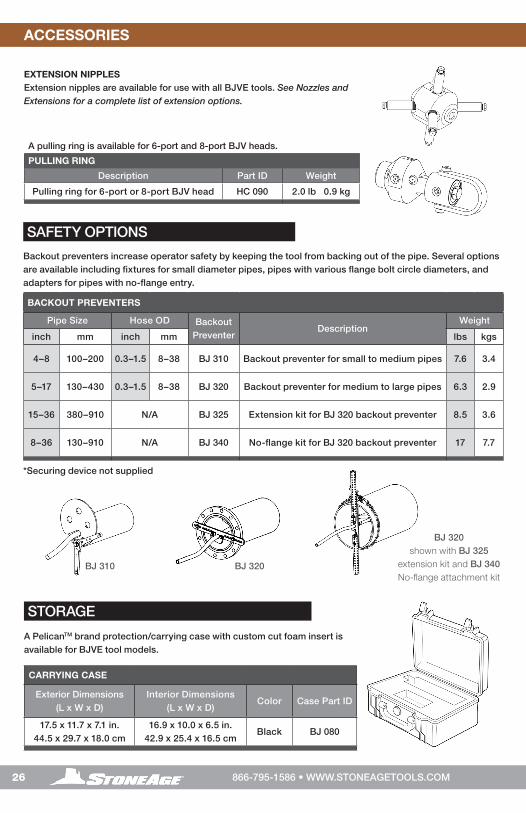
EXTENSION NIPPLESExtension nipples are available for use with all BJVE tools. See Nozzles and Extensions for a complete list of extension options.
A pulling ring is available for 6-port and 8-port BJV heads.
PULLING RING
Description Part ID Weight
Pulling ring for 6-port or 8-port BJV head HC 090 2.0 lb 0.9 kg
SAFETY OPTIONS
Backout preventers increase operator safety by keeping the tool from backing out of the pipe. Several options are available including fixtures for small diameter pipes, pipes with various flange bolt circle diameters, and adapters for pipes with no-flange entry.
BACKOUT PREVENTERS
Pipe Size Hose OD Backout Preventer
DescriptionWeight
inch mm inch mm lbs kgs
4–8 100–200 0.3–1.5 8–38 BJ 310 Backout preventer for small to medium pipes 7.6 3.4
5–17 130–430 0.3–1.5 8–38 BJ 320 Backout preventer for medium to large pipes 6.3 2.9
15–36 380–910 N/A BJ 325 Extension kit for BJ 320 backout preventer 8.5 3.6
8–36 130–910 N/A BJ 340 No-flange kit for BJ 320 backout preventer 17 7.7
*Securing device not supplied
BJ 310 BJ 320
BJ 320shown with BJ 325
extension kit and BJ 340 No-flange attachment kit
ACCESSORIES NOTES
27866-795-1586 • WWW.STONEAGETOOLS.COM
ACCESSORIES NOTES

28 866-795-1586 • WWW.STONEAGETOOLS.COM
TERMS AND CONDITIONS AND WARRANTY INFORMATIONTERMS AND CONDITIONS AND WARRANTY INFORMATION
BJV-P16, BJV-P12, BJV-M24, BJV-MP12
1. Acceptance of Terms and Conditions. Receipt of these
Terms and Conditions of Sale (“Terms and Conditions”) shall
operate as the acceptance by StoneAge, Inc. (“Seller”) of the
order submitted by the purchaser (“Buyer”). Such acceptance
is made expressly conditional on assent by Buyer to these
Terms and Conditions. Such assent shall be deemed to have
been given unless written notice of objection to any of these
Terms and Conditions (including inconsistencies between
Buyer’s purchase order and this acceptance) is given by Buyer
to Seller promptly on receipt hereof.
Seller desires to provide Buyer with prompt and efficient
service. However, to individually negotiate the terms of each
sales contract would substantially impair Seller’s ability to
provide such service. Accordingly, the product(s) furnished
by Seller are sold only according to the terms and conditions
stated herein and with the terms and conditions stated in any
effective StoneAge Dealer Agreement or StoneAge Reseller
Agreement, if applicable. Notwithstanding any terms and
conditions on Buyer’s order, Seller’s performance of any
contract is expressly made conditional on Buyer’s agreement
to these Terms and Conditions unless otherwise specifically
agreed to in writing by Seller. In the absence of such agreement,
commencement of performance, shipment and/ or delivery
shall be for Buyer’s convenience only and shall not be deemed
or construed to be an acceptance of Buyer’s terms and
conditions.
2. Payment/Prices. Unless other arrangements have been
made in writing between Seller and Buyer, payment for the
product(s) shall be made upon receipt of invoice. The prices
shown on the face hereof are those currently in effect. Prices
invoiced shall be per pricelist in effect at the time of shipment.
Prices are subject to increase for inclusion of any and all taxes
which are applicable and which arise from the sale, delivery or
use of the product(s), and the collection of which Seller is or
may be responsible to provide to any governmental authority,
unless acceptable exemption certificates are provided by Buyer
in accordance with applicable law. Buyer shall pay all charges
for transportation and delivery and all excise, order, occupation,
use or similar taxes, duties, levies, charges or surcharges
applicable to the product(s) being purchased, whether now
in effect or hereafter imposed by any governmental authority,
foreign or domestic.
3. Warranty. SELLER MAKES NO WARRANTIES OR
REPRESENTATIONS AS TO THE PERFORMANCE OF ANY
PRODUCT EXCEPT AS SET FORTH IN THE STONEAGE
LIMITED WARRANTY PROVIDED IN THIS DOCUMENT
4. Delivery. Seller is not obligated to make delivery by a
specified date but will always use its best efforts to make
delivery within the time requested. The proposed shipment
date is an estimate. Seller will notify Buyer promptly of any
material delay and will specify the revised delivery date
as soon as practicable. UNDER NO CIRCUMSTANCES
SHALL SELLER HAVE ANY LIABILITY WHATSOEVER FOR
LOSS OF USE OR FOR ANY DIRECT OR CONSEQUENTIAL
DAMAGESRESULTING FROM DELAY REGARDLESS OF THE
REASON(S).
All product(s) will be shipped F.O.B. point of origin, unless
specifically agreed otherwise, and Buyer shall pay all shipping
costs and insurance costs from that point. Seller, in its sole
discretion, will determine and arrange the means and manner of
transportation of the product(s). Buyer shall bear all risk of loss
commencing with the shipment or distribution of the product(s)
from Seller’s warehouse. Order shortages or errors must
be reported within fifteen (15) business days from receipt of
shipment to secure adjustment. No product(s) may be returned
without securing written approval from Seller.
5. Modification. These Terms and Conditions are intended by
Seller and Buyer to constitute a final, complete and exclusive
expression of agreement relating to the subject matter hereof
and cannot be supplemented or amended without Seller’s prior
written approval.
6. Omission. Seller’s waiver of any breach or Seller’s failure
to enforce any of these Terms and Conditions at any time, shall
not in any way affect, limit or waive Seller’s right thereafter to
enforce and compel strict compliance with every term and
condition hereof.
7. Severability. If any provision of these Terms and Conditions
is held to be invalid or unenforceable, such invalidity or
unenforceability shall not affect the validity or enforceability of
the other portions hereof.

29866-795-1586 • WWW.STONEAGETOOLS.COM
TERMS AND CONDITIONS AND WARRANTY INFORMATION
8. Disputes. Seller and Buyer shall attempt in good faith to
promptly resolve any dispute arising under these Terms and
Conditions by negotiations between representatives who have
authority to settle the controversy. If unsuccessful, Seller and
Buyer shall further attempt in good faith to settle the dispute by
nonbinding third-party mediation, with fees and expenses of
such mediation apportioned equally to each side. Any dispute
not so resolved by negotiation or mediation may then be
submitted to a court of competent jurisdiction in accordance
with the terms hereof. These procedures are the exclusive
procedures for the resolution of all such disputes between the
Seller and Buyer.
9. Governing Law. All sales, agreements for sale, offers to sell,
proposals, acknowledgments and contracts of sale, including,
but not limited to, purchase orders accepted by Seller, shall be
considered a contract under the laws of the State of Colorado
and the rights and duties of all persons, and the construction
and effect of all provisions hereof shall be governed by and
construed according to the laws of such state.
10. Jurisdiction and Venue. Seller and Buyer agree that the
state or federal courts located within the City and County of
Denver, Colorado shall have sole and exclusive jurisdiction over
any litigation concerning any dispute arising under these Terms
and Conditions not otherwise resolved pursuant to Section
9 as well as any alleged defects of any Products or damages
sustained as a result of such alleged defects. Seller and
Buyer further agree that should any litigation be commenced in
connection with such a dispute, it shall only be commenced in
such courts. Seller and Buyer agree to the exclusive
jurisdiction of such courts and neither will raise any objection to
the jurisdiction and venue of such courts, including as a result
of inconvenience.
11. Attorney’s Fees. If any litigation is commenced between
Seller and Buyer, or their personal representatives, concerning
any provision hereof, the party prevailing in the litigation shall
be entitled, in addition to such other relief that is granted, to a
reasonable sum as and for their attorneys’ fees and costs in
such litigation or mediation.
STONEAGE TRADEMARK LIST
View the list of StoneAge’s trademarks and service marks and learn how the trademarks should be used. Use of StoneAge
trademarks may be prohibited, unless expressly authorized.
http://www.StoneAgetools.com/trademark-list/
STONEAGE PATENT DATA
View the list of StoneAge’s current U.S. patent numbers and descriptions.
http://www.sapatents.com
STONEAGE TERMS AND WARRANTY
View StoneAge’s Terms and Warranty Conditions online.
http://www.stoneagetools.com/terms
http://www.stoneagetools.com/warranty
30 866-795-1586 • WWW.STONEAGETOOLS.COM
TERMS AND CONDITIONS AND WARRANTY INFORMATIONTERMS AND CONDITIONS AND WARRANTY INFORMATION
Warranties set forth herein extend only to End-Users, meaning
customers acquiring, or that have previously acquired, a
product manufactured by StoneAge (“Product”) for their own
use and not for resale, either directly from StoneAge Inc.
(“StoneAge”) or from a StoneAge Authorized Dealer or Reseller
(“Dealer”). No warranty of any kind or nature is made by
StoneAge beyond those expressly stated herein.
1. LIMITED WARRANTY PERIOD.
One (1) year high pressure seal and seat parts as described
within the following kits.
BJVE 604-XXX SEAL OVERHAUL Kit (P12, MP12 M24)
BJVE 605 SEAL OVERHAUL KIT (P16 ONLY).
Three (3) years for all other parts in the Product including the
speed control mechanism.
Subject to the limitations and conditions hereinafter set forth,
StoneAge warrants the Product to be free from defects in
workmanship and material from the date of purchase by the
End-User within the limited warranty period and is claimed
no later than six (6) months from the period’s expiration
date. All replacement parts which are furnished under this
Limited Warranty and properly installed shall be warranted
to the same extent as the original Product under this Limited
Warranty if, and only if, the original parts were found to be
defective within the original Limited Warranty Period covering
the original Product. Replacement parts are warranted for the
remainder of the original Limited Warranty Period. This Limited
Warranty does not cover any component part of any Product
not manufactured by StoneAge. Any such component part is
subject exclusively to the component manufacturer’s warranty
terms and conditions.
2. LIMITED WARRANTY COVERAGE. StoneAge’s sole
obligation under this Limited Warranty shall be, at StoneAge’s
option and upon StoneAge’s inspection, to repair, replace or
issue a credit for any Product which is determined by StoneAge
to be defective in material or workmanship. StoneAge
reserves the right to examine the alleged defective Product
to determine whether this Limited Warranty is applicable, and
final determination of limited warranty coverage lies solely
with StoneAge. No statement or recommendation made by
a StoneAge representative, Dealer or agent to End-User shall
constitute a warranty by StoneAge or a waiver or modification
to any of the provisions hereof or create any liability for
StoneAge.
3. WARRANTY SERVICE PROVIDERS. Service and repair of
the Product is to be performed only by StoneAge authorized
service representatives, including Dealers who are authorized
repair centers, with StoneAge approved parts. Information
about StoneAge authorized service representatives can be
obtained through the StoneAge website at www.stoneagetools.
com/service. Unauthorized service, repair or modification of
the Product or use of parts not approved by StoneAge will void
this Limited Warranty. StoneAge reserves the right to change
or improve the material and design of the Product at any time
without notice to End-User, and StoneAge is not obligated to
make the same improvements during warranty service to any
Product previously manufactured.
4. WARRANTY EXCLUSIONS. This Limited Warranty does
not cover, and StoneAge shall not be responsible for the
following, or damage caused by the following: (1) any Product
that has been altered or modified in any way not approved by
StoneAge in advance in writing; (2) any Product that has been
operated under more severe conditions or beyond the rated
capacity specified for that Product; (3) depreciation or damage
caused by normal wear and tear, failure to follow operation or
installation instructions, misuse, negligence or lack of proper
protection during storage; (4) exposure to fire, moisture, water
intrusion, electrical stress, insects, explosions, extraordinary
weather and/or environmental conditions including, but not
limited to lightning, natural disasters, storms, windstorms, hail,
earthquakes, acts of God or any other force majeure event;
(5) damage to any Product caused by any attempt to repair,
replace, or service the Product by persons other than StoneAge
authorized service representatives; (6) costs of normal
maintenance parts and services; (7) damage sustained during
unloading, shipment or transit of the Product; or (8) failure to
perform the recommended periodic maintenance procedures
listed in the Operator’s Manual accompanying the Product.
5. REQUIRED WARRANTY PROCEDURES. To be eligible for
warranty service, the End-User must: (1) report the Product
defect to the entity where the Product was purchased (i.e.
StoneAge or the Dealer) within the Limited Warranty Period
specified in this Limited Warranty; (2) submit the original
invoice to establish ownership and date of purchase; and
(3) make the Product available to a StoneAge authorized
service representative for inspection to determine eligibility for
coverage under this Limited Warranty. This Limited Warranty
shall not extend to any person or entity who fails to provide
proof of original purchase from StoneAge or a Dealer. No
Product may be returned for credit or adjustment without prior
written permission from StoneAge.
WARRANTY:

31866-795-1586 • WWW.STONEAGETOOLS.COM
TERMS AND CONDITIONS AND WARRANTY INFORMATION
6. DISCLAIMER OF IMPLIED WARRANTIES AND OTHER
REMEDIES. EXCEPT AS EXPRESSLY STATED HEREIN
(AND TO THE FULLEST EXTENT ALLOWED UNDER
APPLICABLE LAW), STONEAGE HEREBY DISCLAIMS
ALL OTHER WARRANTIES, EXPRESS OR IMPLIED,
INCLUDING WITHOUT LIMITATION ALL IMPLIED
WARRANTIES OF MERCHANTABILITY OR FITNESS FOR A
PARTICULAR PURPOSE, AND ANY AND ALL WARRANTIES,
REPRESENTATIONS OR PROMISES AS
TO THE QUALITY, PERFORMANCE OR FREEDOM FROM
DEFECT OF THE PRODUCT COVERED BY THIS LIMITED
WARRANTY. STONEAGE FURTHER DISCLAIMS ALL IMPLIED
INDEMNITIES.
7. LIMITATION OF LIABILITY. End-User specifically
acknowledges that the Product may be operated at high
speeds and/or pressures, and that as such it may be inherently
dangerous if not used correctly. End-User shall familiarize
itself with all operation materials provided by StoneAge and
shall at all times use and require its agents, employees and
contractors to use all necessary and appropriate safety devices,
guards and proper safe operating procedures. In no event
shall StoneAge be responsible for any injuries to persons or
property caused directly or indirectly by the operation of the
Product if End-User or any agent, employee, or contractor of
End-User: (1) fails to use all necessary and appropriate safety
devices, guards and proper safe operating procedures; (2)
fails to maintain in good working order such safety devices
and guards; (3) alters or modifies the Product in any way not
approved by StoneAge in advance in writing; (4) allows the
Product to be operated under more severe conditions or
beyond the rated capacity specified for the Product; or (5)
otherwise negligently operates the Product. End-User shall
indemnify and hold StoneAge harmless from any and all liability
or obligation incurred by or against StoneAge, including costs
and attorneys’ fees, to or by any person so injured.
TO THE FULL EXTENT ALLOWED BY APPLICABLE LAW,
STONEAGE SHALL NOT BE LIABLE FOR ANY INDIRECT,
SPECIAL, INCIDENTAL, CONSEQUENTIAL, OR PUNITIVE
DAMAGES (INCLUDING WITHOUT LIMITATION, LOSS OF
PROFITS, LOSS OF GOODWILL, DIMINUTION OF VALUE,
WORK STOPPAGE, INTERRUPTION OF BUSINESS, RENTAL
OF SUBSTITUTE PRODUCT, OR OTHER COMMERCIAL
LOSS EVEN TO THE EXTENT SUCH DAMAGES WOULD
CONSTITUTE DIRECT DAMAGES), WITH RESPECT TO
THE COVERED STONEAGE PRODUCT, OR OTHERWISE
IN CONNECTION WITH THIS LIMITED WARRANTY,
REGARDLESS OF WHETHER STONEAGE HAS BEEN ADVISED
OF THE POSSIBILITY OF SUCH DAMAGES.
IT IS UNDERSTOOD THAT STONEAGE’S LIABILITY, WHETHER
IN CONTRACT, IN TORT, UNDER ANY WARRANTY, IN
NEGLIGENCE, OR OTHERWISE SHALL NOT EXCEED THE
AMOUNT OF THE PURCHASE PRICE PAID BY THE END-USER
FOR THE PRODUCT. STONEAGE’S MAXIMUM LIABILITY
SHALL NOT EXCEED, AND END-USER’S REMEDY IS LIMITED
TO EITHER (1) REPAIR OR REPLACEMENT OF THE DEFECTIVE
WORKMANSHIP OR MATERIAL OR, AT STONEAGE’S
OPTION,(2) REFUND OF THE PURCHASE PRICE, OR (3)
ISSUANCE OF A CREDIT FOR THE PURCHASE PRICE, AND
SUCH REMEDIES SHALL BE END-USER’S ENTIRE AND
EXCLUSIVE REMEDY.
YOU, THE END-USER, UNDERSTAND AND EXPRESSLY
AGREE THAT THE FOREGOING LIMITATIONS ON LIABILITY
ARE PART OF THE CONSIDERATION IN THE PRICE OF THE
STONEAGE PRODUCT YOU PURCHASED.
Some jurisdictions do not allow the limitation or exclusion of
liability for certain damages, so the above limitations and
exclusions may not apply to you. This Limited Warranty gives
you specific legal rights, and you may also have other rights
which vary from jurisdiction to jurisdiction. If any provisions of
this Limited Warranty is held to be invalid or unenforceable,
such invalidity or unenforceability shall not affect the validity or
enforceability of the other portions hereof.

1-866-795-1586 • www.STONEAGETOOLS.com© 2019 StoneAge, Inc. All Rights Reserved