bkool12 portable acu owner’s manual
TRANSCRIPT
Page 1 of 16
Drawing : - TPC483 Issue : - 1 Date : - 14/06/18
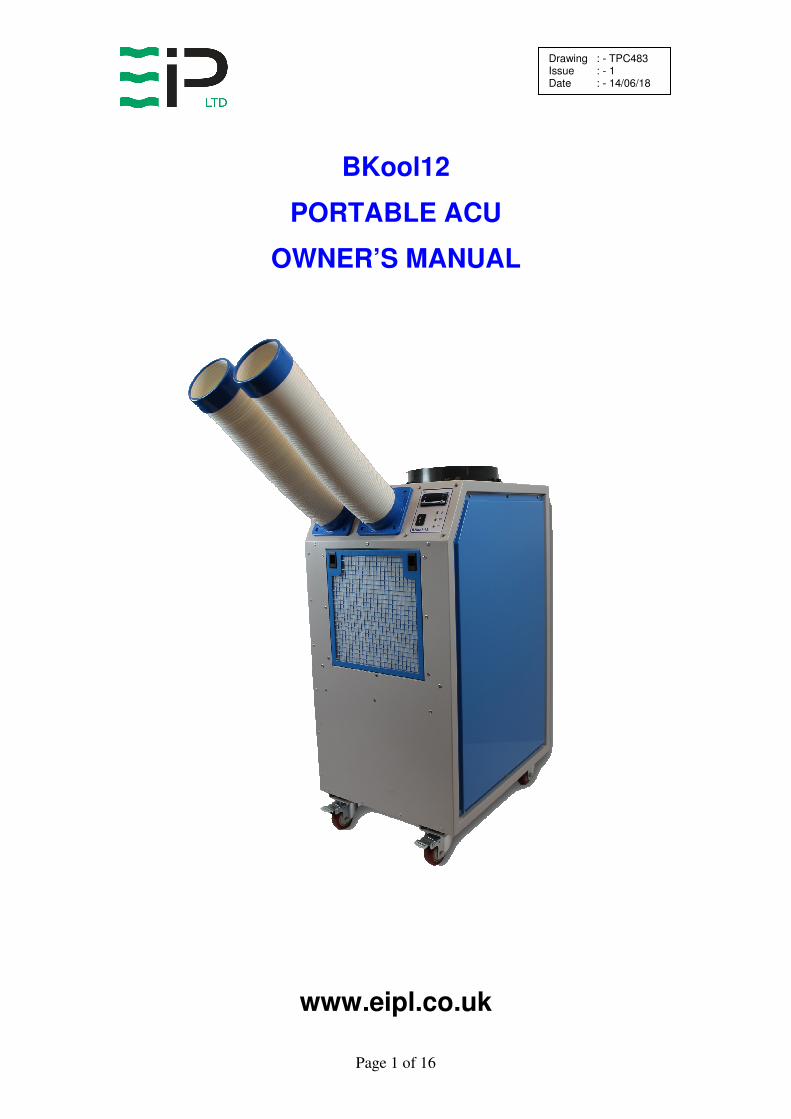
BKool12
PORTABLE ACU
OWNER’S MANUAL
www.eipl.co.uk

Page 2 of 16
Drawing : - TPC483 Issue : - 1 Date : - 14/06/18
BKool12
PACKAGE CONTENTS
Item Description Quantity
10970GB-US BKool12 ACU 1 off
3110461 Flexible Duct 2 off
TPC483 Manual 1 off

Page 3 of 16
Drawing : - TPC483 Issue : - 1 Date : - 14/06/18
INTRODUCTION Heat is a form of energy, cooling is means of transfering the heat from one object to another. In the case of Air conditioning, sensible heat is removed from the indoor space and replaced with cooler air, and the warm air removed is exhausted outside the space being conditioned. This process gradually reduces / maintains the inside temperature. Air Conditioning is most commonly used to achieve a more comfortable interior environment, typically for humans or animals. However, air conditioning is also used to cool rooms filled with heat-producing electronic items, such as computer server rooms. Spot Coolers allow the cool air to be directed towards specific objects or people. An ACU consists of a motor-compressor unit, a refrigerant condenser, two air circulating fans, a refrigerated surface, a means of collecting and disposing the condensed moisture and a cabinet to house these components. The evaporator fan draws air through the refrigerated surface cooling it and removing moisture which is collected and led away. This air is then returned to the room at a much colder temperature providing the cooling effect and with a lower relative humidity than when the air entered the unit. Continuous circulation of the room air through the ACU evaporator gradually reduces the temperature and relative humidity in the room. The condenser fan draws air over the hot condenser which keeps the refrigerated surface cold. This air stream should ideally be ducted out of the area being cooled as it will leave the unit much warmer than the air entering the unit. A digital thermostat is included which allows for precise temperature control. A programmable display lets you set a specific desired temperature level. The BKool12 is a rugged reliable cooling unit designed to operate effectively over a broad range of temperatures. A defrost system, controlled by a frostat, guarantees de-icing and thereby optimizing operation at low temperatures. The unit incorporates a welded steel chassis and is finished in epoxy coated steel covers for resilience to damage caused by rough handling.
The BKool12 has a number of special features:
• Defrost system
• Large water container for moisture removed
• Provision for condensate pump drainage
• Exterior epoxy powder-coated finish
• Large durable castors for easy manoeuvrability
• Status Indicators
• Digital Thermostat Controller
• High and low pressure cut outs

Page 4 of 16
Drawing : - TPC483 Issue : - 1 Date : - 14/06/18
SPECIFICATIONS
"This product contains fluorinated greenhouse gases covered by the Kyoto Protocol. The
refrigeration system is hermetically sealed.
The Global Warming Potential (GWP) of refrigerants used in products manufactured by Ebac Industrial Products Ltd is as follows
R134a – 1300 R407c – 1610
For type and weight of refrigerant contained in this unit, please refer to the product data label"
MODEL: 102970GB-US
COOLING CAPACITY 12000 BTU (@27°C / 60% RH)
HEIGHT: 45” / 1130mm
WIDTH: 20” / 500mm
DEPTH: 26” / 675mm
WEIGHT: 194 lbs / 88 kg
EVAPORATOR AIRFLOW: 377 cfm / 640 M3/Hr
EVAPORATOR OUTLET DIA: 2 X 100mm
CONDENSER AIRFLOW: 1120 cfm / 1900 M3/Hr
CONDENSER OUTLET DIA: 310mm
SOUND LEVEL: 69.7 dB(A)
POWER SUPPLY: 220V - 60Hz - 1 ph
RUNNING CURRENT: 7A
OPERATING RANGE: 18°C – 35°C
REFRIGERANT: R410a (450g)
Page 5 of 16
Drawing : - TPC483 Issue : - 1 Date : - 14/06/18
INSTALLATION POSITIONING: Position the ACU unit in the center of the room to be conditioned if at all possible. However, if a specific area needs to be cooled then place the unit and the cool air outlets over these areas. NOTE: all air inlets and all air outlets of the ACU unit must have clear space around them and not be obstructed in anyway. For correct installation and operation the unit must have a clearance of 0.5M from all adjacent surfaces and or structures. DUCTING: The evaporator air can be directed to a desired area with the flexible ducts provided with the ACU unit. The two flexible ducts are provided in a separate box within the unit packaging. These ducts MUST BE FITTED to the ACU unit BEFORE SWITCHING THE UNIT ON. To fit the ducts, remove the 8 off fixings located on the top sloped face around the outlet cut outs. Place the duct into position on the sloped face and then fix in place with the removed fixings. Ideally the condenser air outlet should be ducted out of the room / area being cooled. POWER SUPPLY: Plug the unit into a suitable supply and the unit is ready for operation If the SUPPLY CORD is damaged, it must be replaced by the manufacturer, its service agent or similarly qualified person in order to avoid hazard. DRAINAGE: The ACU unit has a removable water collection container. This must be placed into the unit before it will operate.

Page 6 of 16
Drawing : - TPC483 Issue : - 1 Date : - 14/06/18
OPERATION
The following procedures should be followed to test the BKool12 for correct operation:
1. After unpacking, examine all external features to confirm damage-free shipment. Report all defects and damage at once. Connect the power cable to a grounded 13 Amp electrical outlet.
2. Setting the Digital Thermostat
The Digital thermostat is factory preset to give the optimum level of control. Only adjustment of the desired set point is required.
During normal operation, the display shows the current temperature within the space being conditioned.
The required temperature level can be set as follows:
• Press the “S” button once to access the set point
• Press the ▲ or ▼ button to change the display to the desired temperature level
• Press the “S” button again to save the set point – The control returns to displaying the current temperature
3. Check cooling process as follows:
A. Place unit on a level surface.
B. Start up unit by turning the ON/OFF switch to ON. Note the power light illuminates
C. Check the digital thermostat is set to required temperature setting (below room temperature)
D. Check that the compressor is running. This will happen after an
in-built delay of 6 minutes
E. Leave the machine running for 15 minutes.
F. Check cooling ducts are discharging cool air. After a period of time the digital thermostat temperature display should start to decrease until set point is reached at which point the compressor and condenser fan will stop but the evaporator fan will continue.
G. If frost is appearing on the evaporator coil then the unit will
periodically go into defrost. When in defrost the compressor and condenser fan will stop, the evaporator fan will continue and the defrost light will illuminate. Once defrost is achieved the unit will return to normal operation.

Page 7 of 16
Drawing : - TPC483 Issue : - 1 Date : - 14/06/18
If, after carrying out the above procedures, the unit does not appear to function properly, refer to the Trouble Shooting section, which follows, or contact the Factory Service Centre. DRAINAGE The ACU unit has a removable water collection container. This must be placed into the unit before it will operate. When the bucket fills it will automatically turn the unit off before over flowing. This container will need emptying on a regular basis so the ACU unit can provide continuous cooling. Access to the container is gained via the small service door and quick release catches, located on the side of the unit. If the bucket is missing or full, as well as the unit not operating, it will illuminate the bucket fault light. A condensate pump can be fitted to provide continuous drainage. Please contact EIPL or your distributor for further information. PRESSURE STATS The ACU unit is fitted with a low pressure stat and a high pressure stat. These pressure stats are connected to the refrigeration system are safety devices designed to protect the refrigeration components. If one of the pressure stats are activated then the pressure fault indicator light will illuminate and the following should be carried out.
A. Switch unit off and leave for a minimum of 5 minutes B. Check the air inlets are not blocked. C. Ensure that the unit is operating within specified parameters of
18°C – 35°C D. Switch unit back on, if it restarts then the low pressure stat
tripped and has re-set. E. If the unit does not restart then switch unit off, disconnect from
power supply and manually reset the high pressure switch located within the unit. Restart the unit and check for normal operation.
F. If the unit still does not start or has started and cuts out on pressure switches then the unit should be turned off and disconnected from the power supply. Then contact either the manufacturer, distributor or qualified personnel.
CAUTION: ONCE THE UNIT HAS BEEN SWITCHED OFF, WAIT AT
LEAST FIVE MINUTES BEFORE RESTARTING.

Page 8 of 16
Drawing : - TPC483 Issue : - 1 Date : - 14/06/18
Warnings.
• Due to the high pressures within the refrigeration circuit, under no circumstances must direct heat be applied to the evaporator coil in an attempt to remove the build up of ice.
• No attempt should be made to cut open any part of the refrigeration circuit due to high pressures and gas involved.
• If the unit is switched off at the mains power supply for any reason, the unit must be allowed to stand at rest for at least five minutes before restarting.
If after carrying out the above procedures, the unit does not appear to function properly, refer to the Trouble Shooting section, which
follows, or contact either the manufacturer, distributor or qualified personnel.

Page 9 of 16
Drawing : - TPC483 Issue : - 1 Date : - 14/06/18
ROUTINE SERVICE
To ensure continued full efficiency of the ACU unit, maintenance procedures should be performed as follows:
1. Clean the surface of the evaporator and condenser coils by blowing
the dirt out from behind the fins with compressed air. Hold the nozzle of the air hose away from the coil to avoid damaging the fins. Alternatively, vacuum clean the coils.
2. Check that the fans are rotating freely. The fan motor is sealed for
life and therefore does not need oiling.
3. To check the refrigerant charge, run the unit for 15 minutes. The evaporator coil should be evenly frost coated across its surface. At
temperatures above 25°C, the coil may be covered with droplets of water rather than frost. Partial frosting accompanied by frosting of the thin capillary tubes, indicates loss of refrigerant gas or low charge.
4. Check all wiring connections.
IF ANY OF THE PRECEDING PROBLEMS OCCUR, CONTACT THE EBAC
SERVICE CENTER PRIOR TO CONTINUED OPERATION OF THE UNIT TO
PREVENT PERMANENT DAMAGE.
WARNING: ENSURE THAT THE POWER CORD TO THE MACHINE HAS BEEN DISCONNECTED BEFORE CARRYING OUT ROUTINE SERVICE. THE SERVICING AND REPAIR OF THIS UNIT SHOULD ONLY BE
CARRIED OUT BY A SUITABLY QUALIFIED PERSON.
WARNING: DO NOT STEAM CLEAN REFRIGERATION COILS

Page 10 of 16
Drawing : - TPC483 Issue : - 1 Date : - 14/06/18
REPAIRS
1. Should an electrical component fail, consult the Factory Service Center to obtain the proper replacement part.
2. If refrigerant gas is lost from the machine, it will be necessary to use
a Refrigeration technician to correct the fault. Contact the Factory Service Center prior to initiating this action.
Any competent refrigeration technician will be able to service the
equipment. The following procedure must be used: a. The source of the leak must be determined and corrected. b. The machine should be thoroughly evacuated before
recharging. c. The unit must be recharged with refrigerant measured
accurately by weight. d. For evacuation and recharging of the machine, use the crimped
charging stubs located near pressure switches.
The charging stub should be crimped and rebrazed after servicing. NEVER allow permanent service valves to be fitted to any part of the circuit. Service valves may leak causing further loss of refrigerant gas.
3. The refrigerant compressor fitted to the dehumidifier is a durable
unit that should give many years of service. Compressor failure can result from the machine losing its refrigerant gas. The compressor can be replaced by a competent refrigeration technician.
Failure of the compressor can be confirmed by the following
procedure: a. Establish that power is present at the compressor terminals
using a voltmeter.
b. With the power disconnected, check the continuity of the internal winding by using meter across the compressor terminals. An open circuit indicates that the compressor should be replaced.
c. Check that the compressor is not grounded by establishing that
a circuit does not exist between the compressor terminals and the shell of the compressor.

Page 11 of 16
Drawing : - TPC483 Issue : - 1 Date : - 14/06/18
TROUBLESHOOTING
SYMPTOM CAUSE REMEDY
Unit inoperative 1. No power to unit 1. Check the power from power supply panel
Little or no airflow
1. Fan motor burnt out 2. Dirty refrigeration coils / filter 3. Loose electrical wiring
1. Replace the fan motor 2. See Routine Maintenance Section 3. Check the wiring diagram to find fault and repair
Little or no defrost when required
1. Faulty frostat 2. No airflow
1. Contact the Factory Service Center 2. Contact the Factory Service Center
Unit vibrates excessively
1. Loose compressor 2. Damaged fan
1. Tighten the nuts on the compressor mounts 2. Replace fan
Water flooding inside the machine
1. Drain pipe blocked/frozen 2. Drain pipe too high 3. Crimped or blocked tubing
1. Clear the obstruction 2. Ensure that no section of the drain hose is above the level of the water outlet 3. Straighten, clear, or replace tubing

Page 12 of 16
Drawing : - TPC483 Issue : - 1 Date : - 14/06/18
BKool12 SPARE PARTS LIST
NUMBER DESCRIPTION PART NUMBER QUANTITY
1 Timer 1
2 Evaporator Coil 2097044 1
3 Condenser Coil 2097045 1
4 Evaporator Fan 3040332 1
5 Condenser Fan 3040329 1
6 Compressor 3944947 1
7 Capillary 3014249 2 x 4ft
8 Filter Dryer 3020957 1
9 Low pressure stat 3021156 1
10 High pressure stat 3021154 1
11 Frostat 3031516 1
12 Relay 3030270 1
13 Temperature Controller 3031522 1
14 Temperature sensor 3033379 1
15 Micro switch 3033044 2
16 On/Off switch 3035914 1
17 Fixed castor 3050206 2
18 Swivel castor with brake 3050208 2
19 Bucket spring 3090752 1
20 Condensate container 3100704 1
21 Condensate container cap 3100705 1
22 Flexible outlet duct 3110461 2
23 Contactor 3930733 1
24 Red LED 3931717 1
25 Green LED 3931718 1
26 Orange LED 3931720 1
27 Male plug 3934540 1
28 Female socket 3934541 1
29 Mains Cable 3035148 1
30 Quick release catch 3088539 4
Spare parts available online
www.EIPLDIRECT.com

Page 13 of 16
Drawing : - TPC483 Issue : - 1 Date : - 14/06/18
WARNINGS
This appliance can be used by children from 8 years and above and persons with reduced physical, sensory or mental capabilities or lack of experience
and knowledge if they have been given supervision or instruction concerning use of the application in a safe way and understand the hazards involved.
Children shall not play with the appliance.
Cleaning and user maintenance shall not be made by children without
supervision.
If the SUPPLY CORD is damaged, it must be replaced by the manufacturer, its service agent or similarly qualified person in order to avoid hazard.
This product contains fluorinated greenhouse gases covered by the Kyoto
Protocol. The refrigeration system is hermetically sealed.
The Global Warming Potential (GWP) of refrigerants used in products manufactured by Ebac Industrial Products Ltd is as follows
R134a – 1300 R407c – 1610
For type and weight of refrigerant contained in this unit, please refer to the
product data label
Due to the high pressures within the refrigeration circuit, under no circumstances must direct heat be applied to the evaporator coil in an attempt
to remove the build-up of ice.
No attempt should be made to cut open any part of the refrigeration circuit due to high pressures and gas involved.
If the unit is switched off at the mains power supply for any reason, the unit must be allowed to stand at rest for at least three minutes before restarting.
For correct installation and operation the unit inlet and outlet must have a
clearance of 0.5M from all adjacent surfaces and or structures.
Page 14 of 16
Drawing : - TPC483 Issue : - 1 Date : - 14/06/18

Page 15 of 16
Drawing : - TPC483 Issue : - 1 Date : - 14/06/18

Page 16 of 16
Drawing : - TPC483 Issue : - 1 Date : - 14/06/18
UK Head Office
Ebac Industrial Products Ltd St Helens Trading Estate
Bishop Auckland County Durham
DL14 9AD
Tel: +44 (0) 1388 664400 Fax: +44 (0) 1388 662590
www.eipl.co.uk
American Sales Office
Ebac Industrial Products Inc 700 Thimble Shoals Blvd. Suite 109, Newport News
Virginia, 23606-2575 USA
Tel: +01 757 873 6800 Fax: +01 757 873 3632
www.ebacusa.com
German Sales Office
Ebac Industrial Products Ltd. Gartenfelder Str. 29-37
Gebäude 35 D-13599, Berlin
Germany
Tel: +49 3043 557241 Fax: +49 3043 557240
www.eip-ltd.de