bladder tank manual docs/robwen/single... · 2012-05-31 · operation manual robwen single tank...
TRANSCRIPT
OPERATION MANUAL
ROBWEN SINGLE TANK FOAM
Distributed By:
ROBWEN inc. 1989 Blake Avenue
Los Angeles, California 90039 U.S.A.
(800)365-9281 (323)665-5633 (323)665-2588
U.S. Patent #5,009,244

CONTENTS
Component Description Installation Summary Operation Reverse Flush Procedures Exploded View Diagram – Metering Valve Exploded View Diagram – Selector Valve Exploded View Diagram – Differential Pressure Valve Exploded View Diagram – Main Body And Bladder Maintenance Description Of Limited Warranty Trouble Shooting Guide Parts List Plumbing Diagram
COMPONENT DESCRIPTION
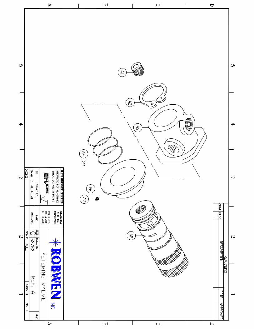
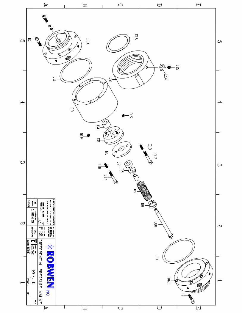
Selector Valve The Selector Valve is a two port, three way valve that has the following settings: OFF, Foam and Refill. In the OFF position, the foam concentrate is bypassed for straight water applications. In the FOAM position, the valve allows water from the high pressure side of the Differential Pressure Valve to flow through one of the ports into the bladder tank. The water exerts line pressure on the bladder and forces the foam concentrate out of the top of the bladder tank, through the Selector Valve and into the Metering Valve. The metered foam concentrate then flows at the same pressure as the hose or the pump plumbing into the Differential Pressure Valve on the lower side. In the REFILL position, the foam concentrate flows from the refill pump into the bladder tank. Placing the Selector Valve in the REFILL position also relieves pressure inside the bladder tank. Refill Pump The refill pump included with the single tank foam system is a 12 volt or 24 volt electric transfer pump. The pump can transfer foam to the bladder tank from either a pail of foam concentrate or from an on-board foam tank. As the pump transfers foam concentrate to the bladder tank, the bladder expands. Water on the outside of the bladder will be discharged to the ground via the water overflow line off of the Selector Valve. The bladder is full once this flow of water stops. It is best to position this overflow line where the pump operator can view it. A momentary switch is recommended but not included. Metering Valve The Metering Valve is infinitely adjustable from .1% to 1.0% for class “A” foam applications. The 3% port is available for AFFF applications and the OFF position is used to turn the foam system off or for straight water application when foam is not desired.
When the Selector Valve is in the FOAM position, the Metering Valve will accurately proportion foam as it passes from the Selector Valve, through the Metering Valve, to the Differential Pressure Valve. Foam concentrates vary in viscosity during colder temperatures; a richer setting may be required to achieve the desired ratio. Drain Cock Each bladder tank has a drain cock located near the bottom. The purpose is to drain the water from the bladder tank in cold weather. To operate the drain cock, rotate counter-clockwise. Place the Selector Valve in the REFILL position, this allows air to enter the bladder tank through the overflow hose and will expedite the drain process. The drain may be remote mounted for easier access. CAUTION: The drain cock must be closed during operation. An open drain during the foam operation will adversely affect the proportioning accuracy.
INSTALLATION SUMMARY
There are four basic components involved in the installation of the ROBWEN single tank and dual tank foam systems. They are: the bladder tank(s), the differential pressure valve, the control panel (metering valve, selector valve(s), flush valve(s)) and the refill pump. The bladder tank(s) may be installed anywhere on the truck. We suggest that the tank(s) be installed vertically, but if necessary, may be installed horizontally. The control valves are pre-assembled on a mounting plate and ideally would be located on the pump panel. The differential pressure valve is plumbed into the discharge side of the pump. A spring-loaded check valve must be plumbed in between the pump and the differential pressure valve. The location of the differential pressure valve in the manifold plumbing will determine how many discharges have foam capability. A typical installation would offer two crosslays and a rear discharge plumbed for foam. On multiple discharge installations, select one 2 ½” port off of the pump manifold. Off of this port, plumb the check valve and then the high flow differential pressure valve.
(4)

On the discharge side of the differential pressure valve, install a 2 ½” four-way cross. This cross can then be reduced to 1 ½” and then plumbed to three discharges. Install the refill pump near the pump panel. When the four basic components have been installed, the plumbing can then be completed as shown in the plumbing diagram. Brass or stainless fittings must be used. Half inch I.D. hydraulic hose of at least 400 PSI working pressure must be used for the plumbing runs.
OPERATION
ROBWEN foam systems are shipped and installed dry. Before operating for the first time, follow these procedures.
1. Turn Flush Valve to the FOAM position.
2. Turn the Selector Valve to the REFILL position.
3. Put refill hose in pail of foam if refilling from a pail of concentrate.
4. Set the Metering Valve to 1%.
5. Activate the transfer pump for 1 minute and then shut down. Turn the Selector Valve to the FOAM position. This will allow any air build up to escape. Return the Selector Valve to the REFILL position and activate the transfer pump. Repeat this process until the system is full. ( 5 gallons in the case of the Model 500, 7 ½ gallons in the case of the Model 750 etc.). This interruption of the refill process is only necessary on the initial fill.
6. Turn the Selector Valve to the FOAM position.
7. Turn the Metering Valve to the desired setting. For richer foam or when in cold
weather, as viscosity increases, use a richer setting. For leaner foam decrease the setting.
(5)
REVERSE FLUSH PROCEDURES
In order to insure accurate, trouble-free operation, it is important to flush the system after each use. The reverse flush technique is as follows.
1. Run water pump at idle.
2. Put nozzle in the off position (closed).
3. Turn the Selector Valve to the REFILL position and then to the FOAM position.
4. Turn the Flush Valve to the FLUSH position.
5. Turn the Metering Valve to 1%. Flush water will discharge from the Flush Valve to the ground. Run with the Metering valve at 1% for 15 seconds and then slowly rotate the Metering Valve 360 degrees..
6. Turn the Selector Valve to the OFF position.
7. Turn the Flush Valve to the FOAM position.
(6)


MAINTENANCE
ROBWEN foam systems are designed to offer hours and hours of trouble free operation while requiring minimal maintenance. The most important maintenance procedure is to perform the reverse flush operation described earlier in this document. Other than that, it is best to employ the “if it’s not broke, don’t fix it” rule. There are two o-rings in the Selector Valve and four o-rings in the Metering Valve. It is not necessary to inspect these as the most common cause of a damaged o-ring is the insertion or removal of the valve parts. If there is an o-ring problem, you will know right away as you will notice foam leaking around the valve handles on the front of the control panel. We expect to see a foam bladder last from five to ten years depending on usage. It is not necessary to inspect the bladder. It is normal to see some foam in the water that discharges during the refill process. The symptoms of a bad bladder are sloppy foam at the higher Metering Valve settings and/or heavy foam discharging in the refill water. Should you have a bad bladder, the replacement process is as follows.
1. Eliminate all of the contents of the bladder (pump at 3% to expedite). 2. Open the drain cock to drain the water from the tank. 3. With a dry tank, unscrew the six bolts at the top of the tank. 4. Remove the top plate (E5). 5. Unscrew the bladder from the bladder stem hose coupling (E6). 6. Install the new bladder.
As the refill pump sees pure foam concentrate, a considerable amount of time and money was spent researching the best pump to use with the system. The Jabsco, equipped with EPDM o-rings and seals, fits the bill. It is recommended that the wires and connections be checked periodically for corrosion. Excessive corrosion can cause a low voltage condition. We suggest that the bladder be topped off after every use.
(7)
ONE YEAR LIMITED WARRANTY
(DESCRIPTION)
Robwen warrants that at the time of shipment, the products manufactured by Robwen and sold hereunder shall be in conformity with applicable written specifications and descriptions referred to or set forth herein, free from defects in material and workmanship, merchantable, and suitable for a particular purpose, provided such is implied by State law under the circumstances of this sale. Robwen agrees to repair or furnish a replacement for, but not to remove or install, any product or component thereof, which, within one (5) years from the date of purchase, shall upon test and examination by Robwen or an authorized dealer, prove defective within the above warranty. No product will be accepted for return without prior notice and authorization by Robwen. Upon such authorization, and in accordance with instruction from Robwen, the product will be returned at Robwen’s expense. Robwen will assume the cost of returning or repairing the damaged goods.
(8)

TROUBLE SHOOTING GUIDE
Problem Check The Following No flow from transfer pump. Make sure Selector Valve is in REFILL. Is bladder already full? Is foam present at origin? Is check valve stuck? Check pump wiring for corrosion. Unable to generate foam at the nozzle. Make sure Selector Valve is in FOAM Make sure Flush Valve is in FOAM Is Metering Valve open? Is there foam in the bladder Water is dripping from refill discharge. This normally occurs when a foam agent Tank is installed higher than the Robwen Control panel. Foam can gravity feed from The tank to the Flush Valve. To correct, Turn the Flush Valve to FOAM Excessive foam discharges during refill Some foam will discharge during the refill Process. If you observe near pure foam During this process, the bladder will require Inspection. Make sure the Flush Valve is in the FOAM Position.
(9)
ROBWEN FOAM SYSTEMS - Bronze Style Parts List
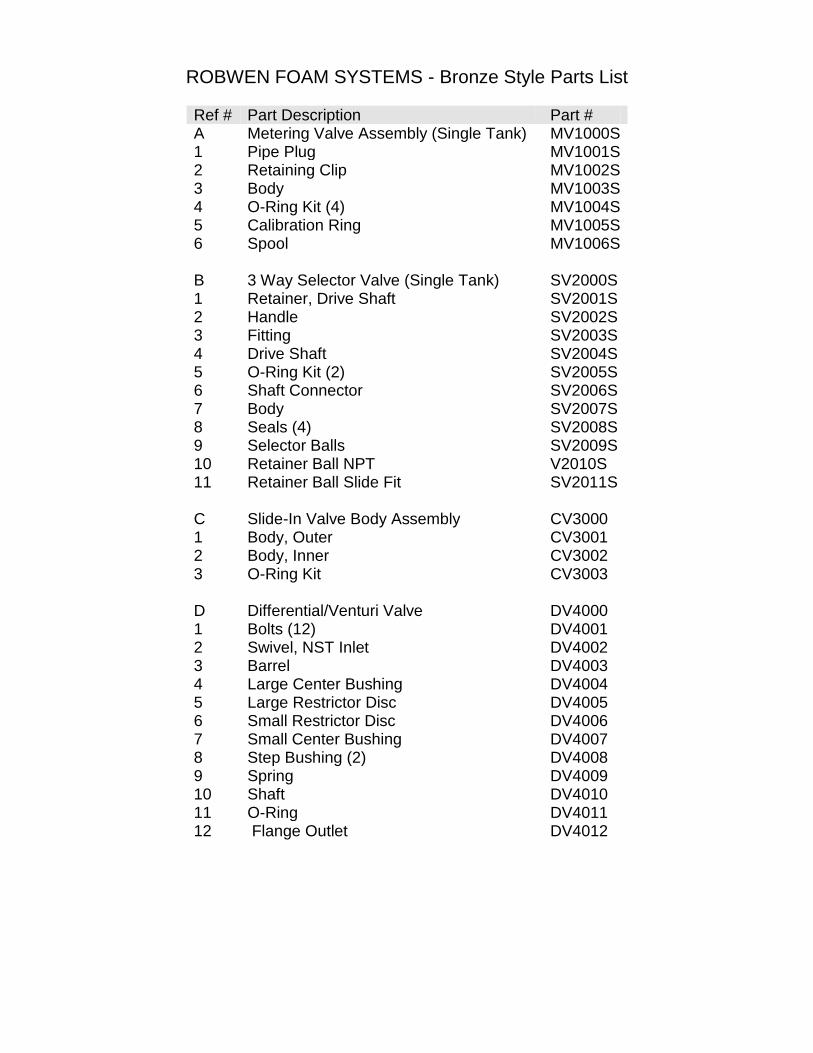
Ref # Part Description Part # A Metering Valve Assembly (Single Tank) MV1000S 1 Pipe Plug MV1001S 2 Retaining Clip MV1002S 3 Body MV1003S 4 O-Ring Kit (4) MV1004S 5 Calibration Ring MV1005S 6 Spool MV1006S B 3 Way Selector Valve (Single Tank) SV2000S 1 Retainer, Drive Shaft SV2001S 2 Handle SV2002S 3 Fitting SV2003S 4 Drive Shaft SV2004S 5 O-Ring Kit (2) SV2005S 6 Shaft Connector SV2006S 7 Body SV2007S 8 Seals (4) SV2008S 9 Selector Balls SV2009S 10 Retainer Ball NPT V2010S 11 Retainer Ball Slide Fit SV2011S C Slide-In Valve Body Assembly CV3000 1 Body, Outer CV3001 2 Body, Inner CV3002 3 O-Ring Kit CV3003 D Differential/Venturi Valve DV4000 1 Bolts (12) DV4001 2 Swivel, NST Inlet DV4002 3 Barrel DV4003 4 Large Center Bushing DV4004 5 Large Restrictor Disc DV4005 6 Small Restrictor Disc DV4006 7 Small Center Bushing DV4007 8 Step Bushing (2) DV4008 9 Spring DV4009 10 Shaft DV4010 11 O-Ring DV4011 12 Flange Outlet DV4012
