blade sweep and reversibility of axial flow fanconsideration during the preliminary design. my...
TRANSCRIPT
Blade sweep and reversibility of axial flow fan
PhD thesis
Dániel Fenyvesi
Gödöllő 2014

Doctoral school denomination: Technical Science Doctoral School
Science: Basics of Agricultural Machine Engineering
Leader: Prof. Dr. István Farkas
Dr. of Technical Sciences
Faculty of Mechanical Engineering
Szent István University, Gödöllő, Hungary
Supervisor: Prof. Dr. Ferenc Szlivka
professor, CSc
Mechatronical and Autotechnical Institution
Donát Bánki Faculty of Mechanical and Safety Engineering
Óbudai University, Budapest, Hungary
……………………………………………… ..…………………………… Affirmation of the Doctoral School Leader Affirmation of Supervisor

1
TABLE OF CONTENTS
NOMENCLATURE 1. INTRODUCTION AND OBJECTIVES
1.1. Importance of the chosen thesis 1.2. Aims and goals 2. MATERIAL AND METHODS
2.1. Rotor calculating with the help of constant chord method, preliminary design
2.2. Swept blade design with prescribed diffusion factor method 2.3. Designing reversible rotor 2.4. Validation of applied numerical model
3. RESULTS 3.1. Rotor tip gap analyzing which designed with constant chord
and diffusion number 3.1.1. Calculation discharge coefficient of tip gap 3.1.2. Rotor hydraulic efficiency 3.1.3. Describing 3D fluid flow with averaged parameters 3.1.4. Investigation of flow blockage 3.1.5. Static pressure distribution at blade tip
3.2. Numerical investigation of swept blade design with prescribed design local diffusion factor method
3.2.1. Pressure distribution along blade profile, stagnation pressure loss
3.2.2. Pressure distribution in the area of blade clearance 3.2.3. Investigation of streamline pattern along the plain 3.2.4. Connection of velocity area blockage, radial flow and
stagnation pressure increasing 3.3. Investigation of reversible rotor
4. NEW SCIENTIFIC RESULTS 5. CONCLUSIONS AND SUGGESTIONS 6. SUMMARY 7. MOST IMPORTANT PUBLICATIONS RELATED TO THE THESIS
2 5 5 5 6 6
7 8
10 11 11
11 11 12 14 14 15
15
16 17 17
19 20 24 25 26

2
NOMENCLATURE blade section stagger angle measured from axial direction [deg]
h hydraulic efficiency [-]
hT designing hydraulic efficiency [-]
angle of blade chord [deg]
tP stagnation pressure difference after and before rotor in absolute frame of reference
[Pa]
cirp pressure changing interpreted into circumferential direction [Pa]
hub to tip ratio [-] density [kg/m3] solidity [-] tip clearance [m] flow coefficient [-]
3 local axial flow coefficient [-] pressure coefficient [-]
meas flow coefficient originated from measure [-]
t designing pressure coefficient [-]
Agy area of torus section [m2] AFB axial flow blockage [-] CL lift coefficient [-]
nC discharge coefficient [-]
Cp static pressure coefficient [-] c chord [m] ca chord at the blade tip [m] ci chord at the blade hub [m] ck chord at the midspan [m] DF diffusion coefficient [-] DFa diffusion number at blade tip [-] DFi diffusion number at blade hub [-] DFk diffusion number at midspan [-]
locDF local diffusion number [-]
DH ratio of inlet- and outlet relative velocity (DE Haller number) [-]
axf unit function of axial flow blockage [-]
h blade span [m] J goodness factor [-] k constant of angular moment [-] n exponent of angular momentum [-]
fn rotor revolution [1/s]
N blade number [-] p pressure [Pa]
3
tp stagnation pressure at the relative frame of reference [Pa]
0p static pressure before leading edge [Pa]
00p stagnation pressure before leading edge interpreted in relative frame of reference
[Pa]
Q volume flow [m3/s] R* dimensionless radius [-] r radius [m] ri hub radius [m] rk midspan radius [m] ra tip radius [m] Re Reynolds number [-] s pitch [m] spn dimensionless coordinate along span [-] u peripheral speed [m/s]
au peripheral speed at blade tip [m/s]
0v inlet relative velocity [m/s]
3mv outlet axial velocity project on the axial direction [m/s]
3uv absolute circumferential velocity behind trailing edge [m/s]
wm, wax relative velocity project on axial direction [m/s]
rw radial velocity [m/s]
sw vector of secondary flow [m/s]
wsb2b secondary velocity on designed 2D plain [m/s]
Nw average velocity through the gap [m/s]
,2N Dw ideal velocity through the gap [m/s]
,2N Dw ideal average velocity through the gap [m/s]
0w inlet relative velocity [m/s]
w3 outlet relative velocity [m/s]
3 2b bw component of outlet relative velocity interpreted in designed plain
[m/s]
2sb bw outlet relative velocity perpendicular on designing plane [m/s]
w average velocity of inlet and outlet velocity at relative frame of reference
[m/s]
max, freew maximum relative velocity at the blade suction surface [m/s]
x coordinate [m]
rY averaged radial flow coefficient [-]
2sb bY averaged secondary flow coefficient [-]
a value at the hub
CFD 3D viscous CFD

4
STR
blade of radial staking line
SW
swept blade (on the hub and tip)
AFB axial flow blockage CVD controlled vortex design FV free-vortex design PS pressure side SS suction side STR straight blade SW positive swept blade (on the hub and tip) TLF tip leakage flow TLV tip leakage vortex VC Vena Contracta

5
1. INTRODUCTION AND OBJECTIVES
1.1. Importance of the chosen thesis
Application of fans in the field of agriculture and industry is very multiplex: airing in animal raising settlements and greenhouses, technological processes of refrigerating plants, drying devices, powder-separating and power plant. A modern ventilation system can have an influence on competitiveness of some agricultural and industrial units. Developing blade rotors can contribute to the economic function.
In the case of improving rotor blade design and for better understanding fluid flow processes in interblade we need get acquainted with 3D-flow processing. For analyzing the 3D flow particularly the main interblade flow phenomena have to be localized like occurrences of hub-separating, tip leakage flow, wall boundary layer flow. During the design flow rate there common interaction has on effect on angular momentum that is hydraulic efficiency of blade row. My aim is to create such a calculating model which can take the above mention loss parameters into consideration and it can estimate their effect during preliminary design. Parameters of preliminary design in the case of this way combined blade geometry are consequences of the monitoring and investigating fluid-flow parameters. According to this the new calculating model needs modern CFD technics and an iterative approaching for goodness-decision.
Synchronized with the above mention facts I have a further aim to investigate the planning parameters and regulablity of flat plate bladed rotor with simple geometry. With application of flat plate blade reversibility can be realized, can become possible. Such simple ventilator construction must be suitable for fulfilling tasks within agricultural airing, for eg. in the case of agricultural produce storing and drying because of the need of bi-directional flow.
1.2. Aims and goals
My aims are the followings: 1. 3D numerical investigation of the rotor designed on controlled vortex deign
(CVD) in the case of different blade leakage. 2. Creating a calculating model based on controlled vortex design method, can
usually cause swept blades and takes the 3D interblade flow phenomena into consideration during the preliminary design. My further aim is the comparing investigation rotors with the new calculating model in spite of traditional straight-stacking-line blade.
3. Designing reversible axial flow fan with simple geometry flat plate blade and analyzing of characteristic.
6
2. MATERIAL AND METHODS 2.1. Rotor calculating with the help of constant chord method, preliminary
design
The preliminary design calculates the straight bladed reference cascade. With the application of controlled vortex design can become possible to choose angular momentum distribution, in order that blade chord remains constant at the radii. During the calculation the absolute tangential velocity is the following:
3n
uv k r (2.1)
I calculate velocity triangles with the help of (2.1) and radial equilibrium equation.
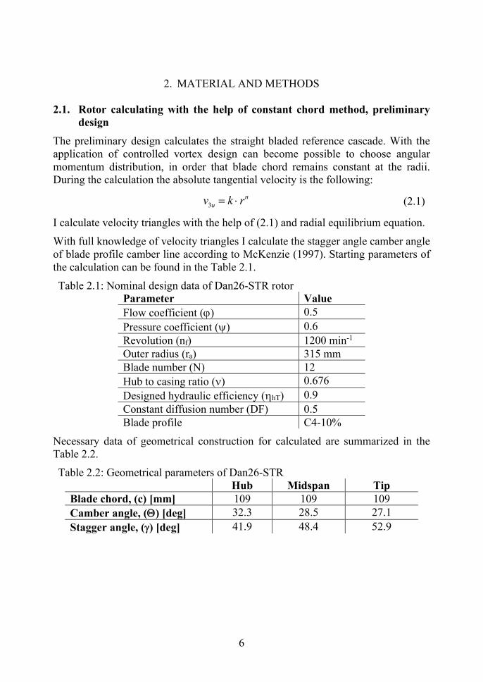
With full knowledge of velocity triangles I calculate the stagger angle camber angle of blade profile camber line according to McKenzie (1997). Starting parameters of the calculation can be found in the Table 2.1.
Table 2.1: Nominal design data of Dan26-STR rotor Parameter Value
Flow coefficient () 0.5
Pressure coefficient () 0.6
Revolution (nf) 1200 min-1 Outer radius (ra) 315 mm Blade number (N) 12
Hub to casing ratio () 0.676
Designed hydraulic efficiency (hT) 0.9
Constant diffusion number (DF) 0.5 Blade profile C4-10%
Necessary data of geometrical construction for calculated are summarized in the Table 2.2.
Table 2.2: Geometrical parameters of Dan26-STR Hub Midspan Tip Blade chord, (c) [mm] 109 109 109
Camber angle, () [deg] 32.3 28.5 27.1
Stagger angle, () [deg] 41.9 48.4 52.9
7
2.2. Swept blade design with prescribed diffusion factor method
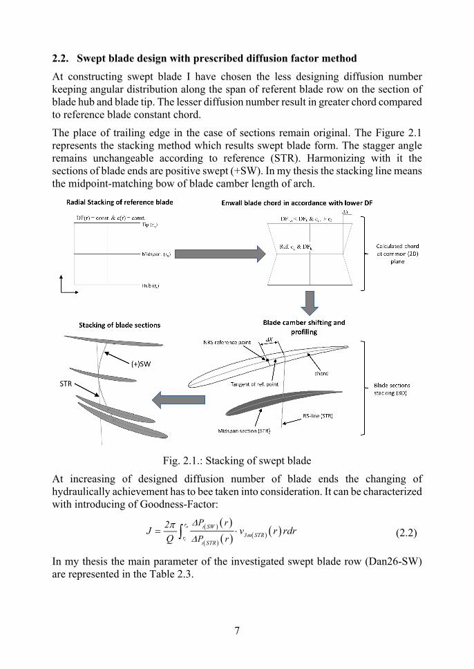
At constructing swept blade I have chosen the less designing diffusion number keeping angular distribution along the span of referent blade row on the section of blade hub and blade tip. The lesser diffusion number result in greater chord compared to reference blade constant chord.
The place of trailing edge in the case of sections remain original. The Figure 2.1 represents the stacking method which results swept blade form. The stagger angle remains unchangeable according to reference (STR). Harmonizing with it the sections of blade ends are positive swept (+SW). In my thesis the stacking line means the midpoint-matching bow of blade camber length of arch.
Fig. 2.1.: Stacking of swept blade
At increasing of designed diffusion number of blade ends the changing of hydraulically achievement has to bee taken into consideration. It can be characterized with introducing of Goodness-Factor:
a
i
t
t
r SW
3m STRrSTR
P r
P r
2J v r rdr
Q
(2.2)
In my thesis the main parameter of the investigated swept blade row (Dan26-SW) are represented in the Table 2.3.

8
Table 2.3: Geometrical parameters of Dan26-SW blade row Hub Midspan Tip Designing diffusion number
(DF) 0.454 0.5 0.438
Chord, (c) [mm] 143.3 109 143.3
Camber angle, () [fok] 27.2 28.5 22.3
Stagger angle, () [fok] 41.9 48.4 52.9
Views of designed Dan26-SW swept blade (Figure 2.2.).
Fig. 2.2.: Views of designed swept blade (Dan26-SW) a) tangential- (PS), b) axial-, c) from above views
2.3. Designing reversible rotor
During designing blades I realized bi-directional flow with the help of flat plate blade. The main aspect was the simple producing, harmonizing with it we haven’t adjusted edge radius and inlet cone on the hub. Rounding the blade ends has happened according to decreased circle bow with tip clearance size on the blade converted to plain. The blades have been fixed by rivets on the bowed plate.
During designing I have chosen the free-vortex design (FV). In my design I have
considered the blades like free-standing wings 2 . At calculating the blade
solidity (Eck, 2003) I have used the frictionless form of force-factor. I have taken the effect of friction into account, that I take values of lift coefficient from the diagram constructed by measuring the free-standing wing-wind tunnel with consideration of glide. The Table 2.4. contains the parameters prescribed in design working point.
9
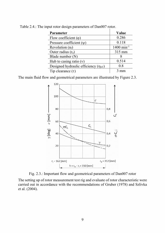
Table 2.4.: The input rotor design parameters of Dan007 rotor.
Parameter Value
Flow coefficient () 0.286
Pressure coefficient () 0.118
Revolution (nf) 1400 min-1 Outer radius (ra) 315 mm Blade number (N) 8
Hub to casing ratio () 0.514
Designed hydraulic efficiency (hT) 0.8
Tip clearance () 3 mm
The main fluid flow and geometrical parameters are illustrated by Figure 2.3.
Fig. 2.3.: Important flow and geometrical parameters of Dan007 rotor
The setting up of rotor measurement test rig and evaluate of rotor characteristic were carried out in accordance with the recommendations of Gruber (1978) and Szlivka et al. (2004).
10
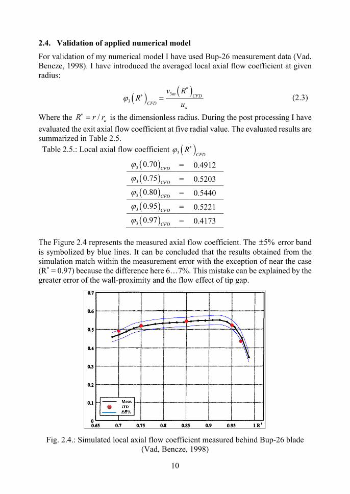
2.4. Validation of applied numerical model
For validation of my numerical model I have used Bup-26 measurement data (Vad, Bencze, 1998). I have introduced the averaged local axial flow coefficient at given radius:
3
3
m CFD
CFDa
v RR
u
(2.3)
Where the / aR r r is the dimensionless radius. During the post processing I have
evaluated the exit axial flow coefficient at five radial value. The evaluated results are summarized in Table 2.5.
Table 2.5.: Local axial flow coefficient 3 CFDR
3 0.70CFD
= 0.4912
3 0.75CFD
= 0.5203
3 0.80CFD
= 0.5440
3 0.95CFD
= 0.5221
3 0.97CFD
= 0.4173
The Figure 2.4 represents the measured axial flow coefficient. The 5% error band is symbolized by blue lines. It can be concluded that the results obtained from the simulation match within the measurement error with the exception of near the case (R* = 0.97) because the difference here 6…7%. This mistake can be explained by the greater error of the wall-proximity and the flow effect of tip gap.
Fig. 2.4.: Simulated local axial flow coefficient measured behind Bup-26 blade (Vad, Bencze, 1998)
11
3. RESULTS
3.1. Rotor tip gap analyzing which designed with constant chord and diffusion number
In my subchapter I analyze the straight bladed fan (STR) with different tip clearances. The investigated tip gap series are nondimensioned by midspan chord. I listed this series of tip gap with percent format: 0.9174ck% (1.0 mm), 1.3761ck% (1.5 mm), 1.8348ck% (2.0 mm), 2.2936ck% (2.5 mm), 2.7523ck% (3.0 mm).
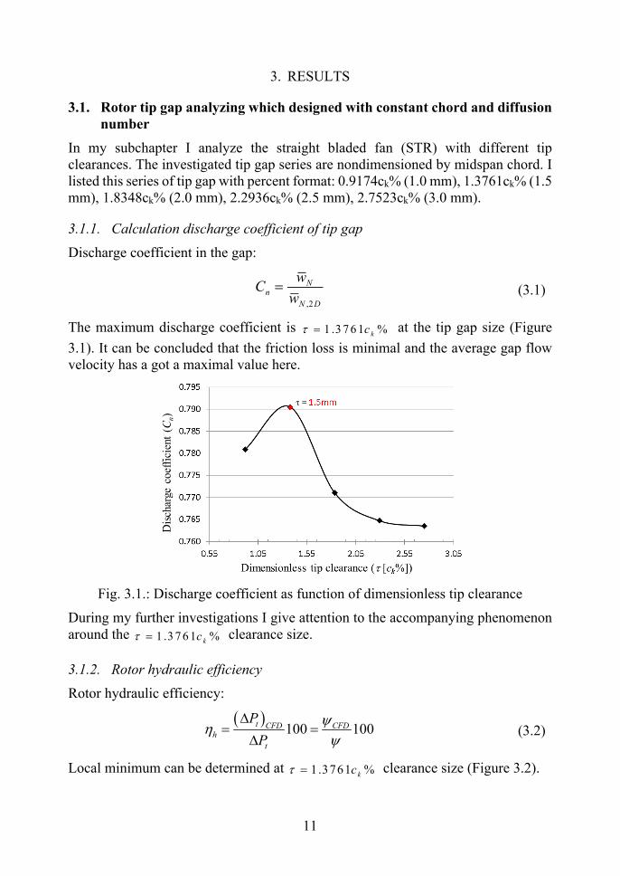
3.1.1. Calculation discharge coefficient of tip gap
Discharge coefficient in the gap:
,2
Nn
N D
wC
w (3.1)
The maximum discharge coefficient is 1 .3 76 1 %kc at the tip gap size (Figure
3.1). It can be concluded that the friction loss is minimal and the average gap flow velocity has a got a maximal value here.
Fig. 3.1.: Discharge coefficient as function of dimensionless tip clearance
During my further investigations I give attention to the accompanying phenomenon around the 1 .3 76 1 %kc clearance size.
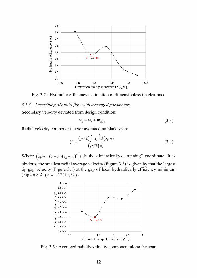
3.1.2. Rotor hydraulic efficiency
Rotor hydraulic efficiency:
100 100t CFDCFD
h
t
P
P
(3.2)
Local minimum can be determined at 1 .3761 %kc clearance size (Figure 3.2).
12
Fig. 3.2.: Hydraulic efficiency as function of dimensionless tip clearance
3.1.3. Describing 3D fluid flow with averaged parameters
Secondary velocity deviated from design condition:
2s r sb b w w w (3.3)
Radial velocity component factor averaged on blade span:
2
2
2
2
r
r
a
w d spnY
u
(3.4)
Where 1
i a ispn r r r r
is the dimensionless „running” coordinate. It is
obvious, the smallest radial average velocity (Figure 3.3) is given by that the largest tip gap velocity (Figure 3.1) at the gap of local hydraulically efficiency minimum (Figure 3.2) .371 61 %kc .
Fig. 3.3.: Averaged radially velocity component along the span
13
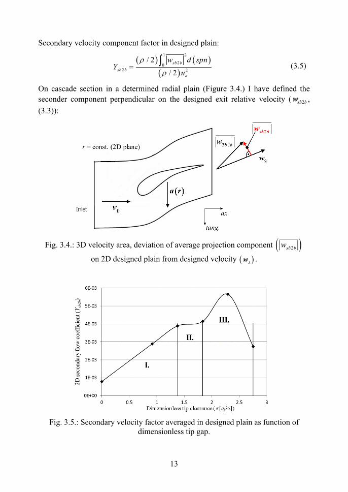
Secondary velocity component factor in designed plain:
21
20
2 2
/ 2
/ 2
sb b
sb b
a
w d spnY
u
(3.5)
On cascade section in a determined radial plain (Figure 3.4.) I have defined the
seconder component perpendicular on the designed exit relative velocity ( 2sb bw ,
(3.3)):
Fig. 3.4.: 3D velocity area, deviation of average projection component 2sb bw
on 2D designed plain from designed velocity 3w .
Fig. 3.5.: Secondary velocity factor averaged in designed plain as function of dimensionless tip gap.
14
The function of a global secondary velocity factor (Ysb2b) can be partitioned into three characteristic ranges (Figure 3.5.): linear, constant and concave stages. The first one (I.) is the linear sector which is 1.3761ck% gap size. The second one (II.) is the constant sector as fa as 1.3761ck% and the last range (III.) is described by a concave function. Tip clearance of 1.3761ck% (1.5mm) which was given as former extrema is located at boundary between linear and constant sectors. At zero gap size the case runs together with rotor during simulation (shrouded rotor).
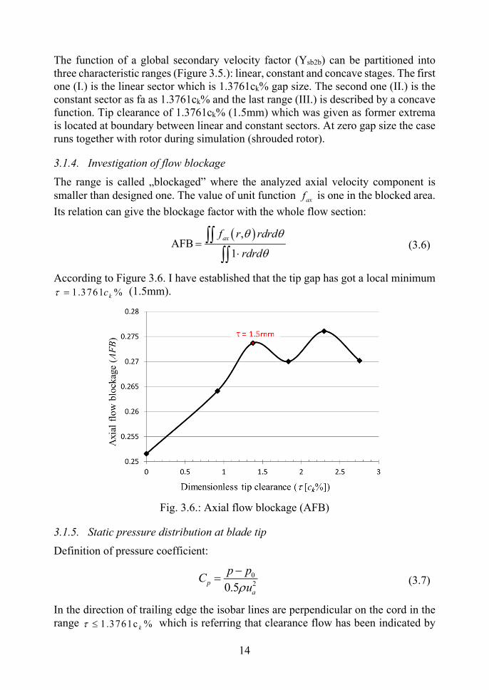
3.1.4. Investigation of flow blockage
The range is called „blockaged” where the analyzed axial velocity component is smaller than designed one. The value of unit function axf is one in the blocked area.
Its relation can give the blockage factor with the whole flow section:
,AFB
1
axf r rdrd
rdrd
(3.6)
According to Figure 3.6. I have established that the tip gap has got a local minimum 1.3761 %kc (1.5mm).
Fig. 3.6.: Axial flow blockage (AFB)
3.1.5. Static pressure distribution at blade tip
Definition of pressure coefficient:
020.5
p
a
p pC
u
(3.7)
In the direction of trailing edge the isobar lines are perpendicular on the cord in the range 1.3761c %k which is referring that clearance flow has been indicated by

15
blade loading here (Yamamoto, 1989). Int he direction of trailing edge at the larger investigated tip clearance 1.3761c %k the isobar lines are kinked, that is the
clearance flow is influenced by viscosity in a higher degree.
In the tip gap range 1.8348c %k the pressure of entering velocity of pressure size
immediately decreases, in consequence of flow section stricture (vena contracta: VC). In the case of tip gap 1.3761c %k (1.5mm) the vena contracta phenomena
has not appeared yet (Figure 3.7.).
0.9174c %k 1.3761c %k 1.8348c %k
2 .2936c %k 2 .7523 %kc
Fig. 3.7.: Static pressure coefficient distribution at the blade tip
3.2. Numerical investigation of swept blade design with prescribed design local diffusion factor method.
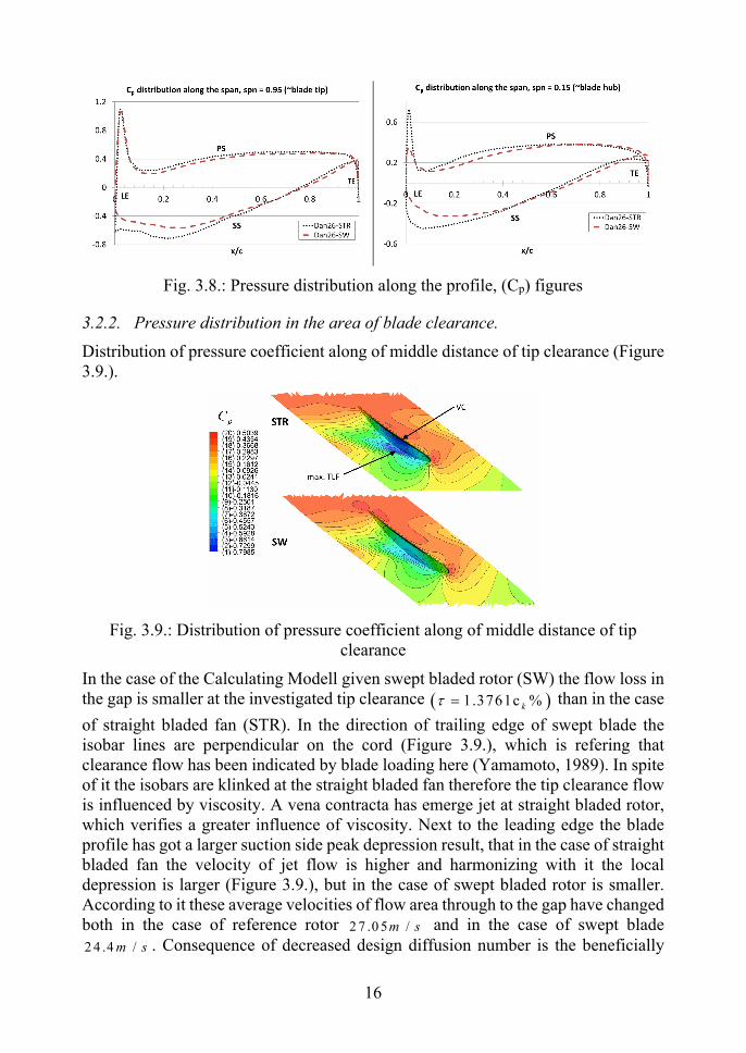
3.2.1. Pressure distribution along blade profile, stagnation pressure loss
At the hub and blade tip peak depression lowering can be noticed (Figure 3.8.). One of the reasons of depression decreasing is (+)SW consequence of blade tips, which results local velocity increasing. The other reason of appearing of decreased suction surface pressure gradient is the result of the smaller design diffusion number (DF):
3max,
max,
~ 1loc free
free
wDF DF DF w
w (3.8)
The smaller diffusion number results a smaller suction surface peak velocity
max, freew :
200 max, max,.
2t free freep p p w áll w p
(3.9)
Where tp is the local stagnation pressure.
16
Fig. 3.8.: Pressure distribution along the profile, (Cp) figures
3.2.2. Pressure distribution in the area of blade clearance.
Distribution of pressure coefficient along of middle distance of tip clearance (Figure 3.9.).
Fig. 3.9.: Distribution of pressure coefficient along of middle distance of tip clearance
In the case of the Calculating Modell given swept bladed rotor (SW) the flow loss in the gap is smaller at the investigated tip clearance 1.3761c %k than in the case
of straight bladed fan (STR). In the direction of trailing edge of swept blade the isobar lines are perpendicular on the cord (Figure 3.9.), which is refering that clearance flow has been indicated by blade loading here (Yamamoto, 1989). In spite of it the isobars are klinked at the straight bladed fan therefore the tip clearance flow is influenced by viscosity. A vena contracta has emerge jet at straight bladed rotor, which verifies a greater influence of viscosity. Next to the leading edge the blade profile has got a larger suction side peak depression result, that in the case of straight bladed fan the velocity of jet flow is higher and harmonizing with it the local depression is larger (Figure 3.9.), but in the case of swept bladed rotor is smaller. According to it these average velocities of flow area through to the gap have changed both in the case of reference rotor 2 7 .0 5 /m s and in the case of swept blade 2 4 .4 /m s . Consequence of decreased design diffusion number is the beneficially
17
smaller gap velocity of swept blade which has got a moderating efficiency on blade loading. The higher discharge coefficient can verify the smaller flow loss of the swept blade in the tip clearance. 0.7884n SW
C is at the swept blade and
0.771n STRC is at straight blade.
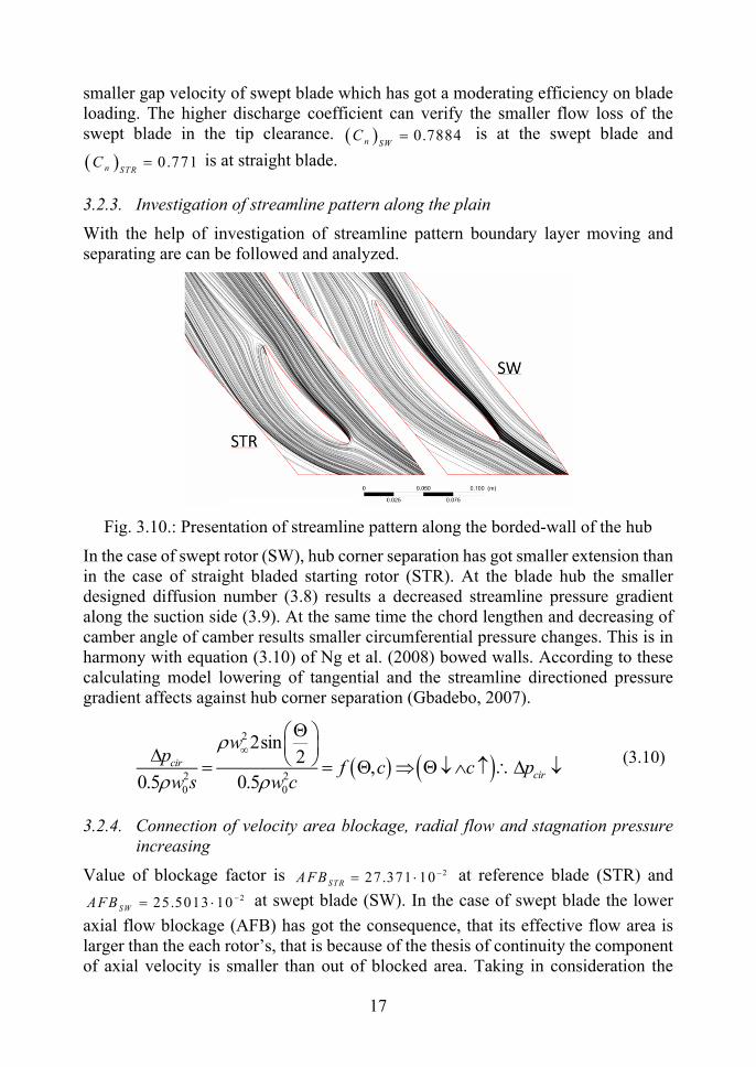
3.2.3. Investigation of streamline pattern along the plain
With the help of investigation of streamline pattern boundary layer moving and separating are can be followed and analyzed.
Fig. 3.10.: Presentation of streamline pattern along the borded-wall of the hub
In the case of swept rotor (SW), hub corner separation has got smaller extension than in the case of straight bladed starting rotor (STR). At the blade hub the smaller designed diffusion number (3.8) results a decreased streamline pressure gradient along the suction side (3.9). At the same time the chord lengthen and decreasing of camber angle of camber results smaller circumferential pressure changes. This is in harmony with equation (3.10) of Ng et al. (2008) bowed walls. According to these calculating model lowering of tangential and the streamline directioned pressure gradient affects against hub corner separation (Gbadebo, 2007).
2
2 20 0
2sin2
,0.5 0.5
circir
wp
f c c pw s w c
(3.10)
3.2.4. Connection of velocity area blockage, radial flow and stagnation pressure increasing
Value of blockage factor is 227.371 10STRAFB at reference blade (STR) and 225.5013 10SWAFB at swept blade (SW). In the case of swept blade the lower
axial flow blockage (AFB) has got the consequence, that its effective flow area is larger than the each rotor’s, that is because of the thesis of continuity the component of axial velocity is smaller than out of blocked area. Taking in consideration the
18
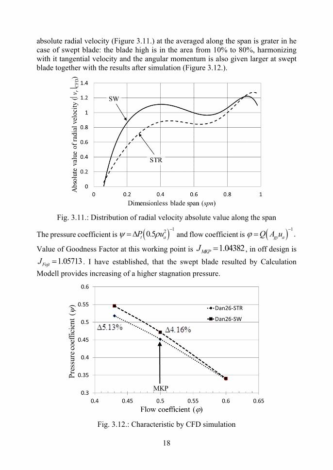
absolute radial velocity (Figure 3.11.) at the averaged along the span is grater in he case of swept blade: the blade high is in the area from 10% to 80%, harmonizing with it tangential velocity and the angular momentum is also given larger at swept blade together with the results after simulation (Figure 3.12.).
Fig. 3.11.: Distribution of radial velocity absolute value along the span
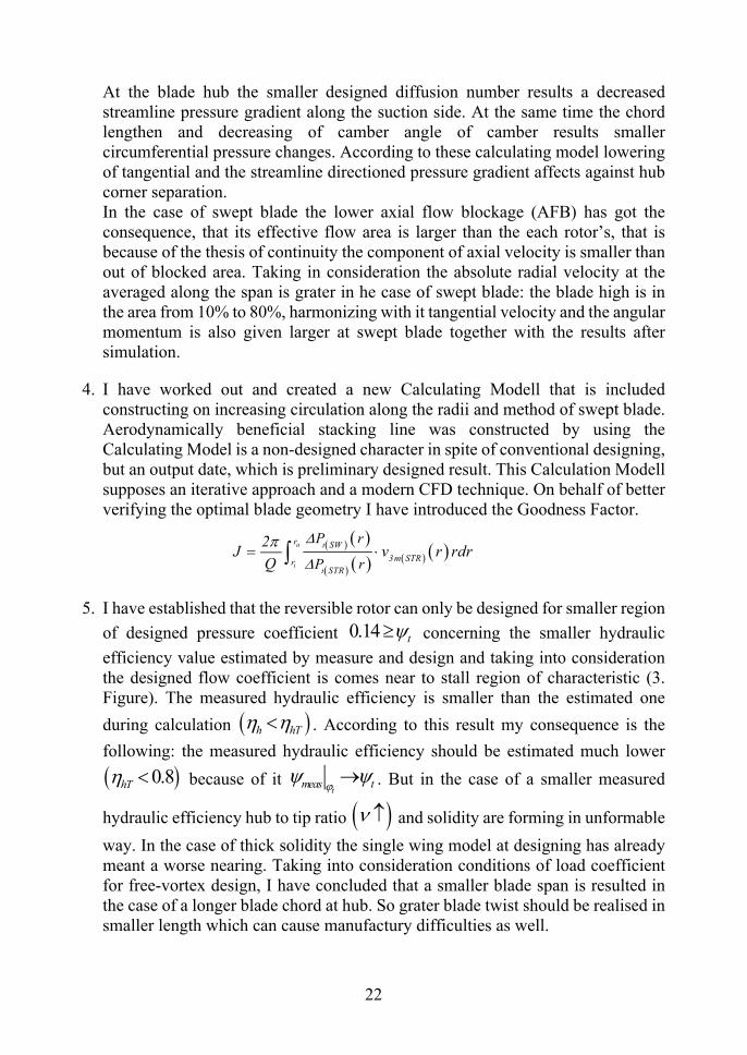
The pressure coefficient is 120.5t aP u
and flow coefficient is 1.gy aQ A u
Value of Goodness Factor at this working point is 1.04382MKPJ , in off design is
1.05713FojtJ . I have established, that the swept blade resulted by Calculation
Modell provides increasing of a higher stagnation pressure.
Fig. 3.12.: Characteristic by CFD simulation

19
3.3. Investigation of reversible rotor
The hydraulic efficiecny of is the following:
0.085100 100 71%
0.12t
meas
h
t
(3.11)
I have established that the reversible rotor can only be designed for smaller region
of designed pressure coefficient 0.14 t concerning the smaller hydraulic
efficiency value estimated by measure and design and taking into consideration the designed flow coefficient is comes near to stall region of characteristic (3.13. Figure). The measured hydrulic efficiency is smaller than the estimated one during
calculation h hT . According to this result my consequence is the following: the
measured hydraulic efficiency should be estimated much lower 0.8hT because
of it t
meas t . But in the case of a smaller measured hydraulic efficiency hub to
tip ratio and solidity are forming in unformable way. In the case of thick
solidity the single wing model at designing has already meant a worse nearing. Taking into consideration conditions of load coefficient for free-vortex design, I have concluded that a smaller blade span is resulted in the case of a longer blade chord at hub. So grater blade twist should be realised in smaller length which can cause manufactory difficulties as well.
Fig. 3.13.: Characteristic of reversible rotor at designed revolution

20
4. NEW SCIENTIFIC RESULTS
The received and represented scientific results of my searching process are the followings:
1. With the help of CFD simulation valided by measure I have demonstrated and manifested that straight bladed fan – onto a constant chord designed by controlled vortex method and and constant diffusion number – has got a local hydraulic efficiency minimum in investigated tip clearance series. I have verified by numerical analysis, that the function of a global secondary velocity factor (Ysb2b) can be partitioned into linear, constant and concave stages (Figure 1.). Besides I have verified that escorting phenomena of tip clearance belongst to local efficiency minimum are the followings: In this case the discharge coefficient was given at the maximum level, that is
the flow loss in the gap is the least and the smallest. The radial velocity factor (Yr) has got a global minimum. The factor of axial velocity blockage (AFB) ha got a local minimum here. A vena contracta in the tip gag has not emerge jet, but in the case of the larger
investigated tip clearance has already been noticed. The global secondary velocity factor (Ysb2b) is located at the boundary of
linear and constant stages. In the direction of trailing edge the isobar lines are perpendicular on the cord,
which is referring that clearance flow has been indicated by blade loading here. In the direction of trailing edge at the larger investigated tip clearance the isobar lines are kinked, that is the clearance flow is influenced by viscosity in a higher degree.
Fig. 1.: Secondary velocity factor averaged in designed plain according to function of dimensionless tip clearance

21
2. With the help of CFD simulation valided by measure the calculating model in the case of the Calculating Modell given by swept bladed rotor (SW) the flow loss in the gap is smaller at the investigated tip clearance 1.3761c %k than in the
case of straight bladed fan (STR). In the direction of trailing edge of swept blade the isobar lines are perpendicular on the cord (Figure 2.), which is referring that clearance flow has been inducated by blade loading here. In spite of it the isobars are klinked at the straight bladed fan therefore the tip clearance flow is influenced by viscosity. A vena contracta has emerge jet at straight bladed rotor, which verifies a greater influence of viscosity. Next to the leading edge the blade profile has got a larger suction side peak depression result, that in the case of straight bladed fan the velocity of jet flow is higher and harmonizing with itt he local depression is larger (Figure 2.), but in the case of swept bladed rotor is smaller. According to the above-mentioned simulation the average velocity of flow area through to the gap is grater in the case of straight bladed fan, but it was given smaller in the case of swept blade. Consequence of decreased design diffusion number is the beneficially smaller gap velocity of swept blade which has got a moderating efficiency on blade loading. The higher discharge coefficient can verify the smaller flow loss of the swept blade in the tip clearance
n nSW STRC C .
Fig. 2.: Distribution of pressure coefficient along of middle distance of tip clearance
3. With the help of CFD simulation valided by measure that the Calculating Modell has resulted the followings in the case of swept rotor, hub corner separation has got smaller extension and the enlargement of stagnation pressure is higher at designed volume flow, than in the case of straight bladed starting rotor.
22
At the blade hub the smaller designed diffusion number results a decreased streamline pressure gradient along the suction side. At the same time the chord lengthen and decreasing of camber angle of camber results smaller circumferential pressure changes. According to these calculating model lowering of tangential and the streamline directioned pressure gradient affects against hub corner separation. In the case of swept blade the lower axial flow blockage (AFB) has got the consequence, that its effective flow area is larger than the each rotor’s, that is because of the thesis of continuity the component of axial velocity is smaller than out of blocked area. Taking in consideration the absolute radial velocity at the averaged along the span is grater in he case of swept blade: the blade high is in the area from 10% to 80%, harmonizing with it tangential velocity and the angular momentum is also given larger at swept blade together with the results after simulation.
4. I have worked out and created a new Calculating Modell that is included constructing on increasing circulation along the radii and method of swept blade. Aerodynamically beneficial stacking line was constructed by using the Calculating Model is a non-designed character in spite of conventional designing, but an output date, which is preliminary designed result. This Calculation Modell supposes an iterative approach and a modern CFD technique. On behalf of better verifying the optimal blade geometry I have introduced the Goodness Factor.
a
i
t
t
r SW
3m STRrSTR
P r
P r
2J v r rdr
Q
5. I have established that the reversible rotor can only be designed for smaller region
of designed pressure coefficient 0.14 t concerning the smaller hydraulic
efficiency value estimated by measure and design and taking into consideration the designed flow coefficient is comes near to stall region of characteristic (3. Figure). The measured hydraulic efficiency is smaller than the estimated one
during calculation h hT . According to this result my consequence is the
following: the measured hydraulic efficiency should be estimated much lower
0.8hT because of it t
meas t . But in the case of a smaller measured
hydraulic efficiency hub to tip ratio and solidity are forming in unformable
way. In the case of thick solidity the single wing model at designing has already meant a worse nearing. Taking into consideration conditions of load coefficient for free-vortex design, I have concluded that a smaller blade span is resulted in the case of a longer blade chord at hub. So grater blade twist should be realised in smaller length which can cause manufactury difficulties as well.

23
Fig. 3.: Characteristic of reversible rotor at designed revolution
24
5. CONCLUSIONS AND SUGGESTIONS
Considering new trends of special field of rotating machinery the aim of my thesis is creating a calculating model and its numerical investigation which takes the 3D effect and the real hydraulical efficiency into consideration during the preliminary design. My calculating model matches the controlled vortex design (CVD) with blade sweep.
The loss swept blade is lower in the blade tip clearance than the loss of preliminary reference rotor. In spite of this fact the blocked area by case behind the trailing edge is nearly the same as because of larger chord. The trailing vortex has gat a longer way for dissipation. We can see that the interaction of several parameters makes influence on goodness of blade flow. That is why I find useful to creating an optimized method of friction interblade flow with considering more multiparameter. This problem is complex because there are more local optimums and their incidental, based on a compromise and their success is not ensured that they contribute to find the global optimum (hydraulically efficiency). Local optimum aim can be eg. lower mixing behind rotor blade row, size of blocked area, streamline path on suction side of blade which is influenced by wall skin friction. The importance of some phenomenon has been balanced, that should be practically determined, in which degree the above mentioned phenomena have influence on changing of goodness factor in my thesis.
We would research some further energetical investigations of effect of higher radial flow behind swept rotor, farther from blade row, mixing loss, or flow interaction in the case of ducted diffusor behind rotor.
I have investigated the effect of different blade clearances referring to fluid for parameters, on behalf of better understanding my calculation I have introduced new parameters as well. I have establish what kind of escorting phenomenon the local hydraulically efficiency minimum has got at decreasing blade clearance. I have worked out numerical model for calculating tip clearance loss referring to analogy of discharge coefficient so I consider useful to involve these received results into the later calculating model.
I have made conclusions according to the investigation of characteristic for designing parameters of reversible flat plate blade. The property of flat plate blade, a simple hub and the blade edges are forms radius-less.

25
6. SUMMARY
On the basis of the technical literature I have reviewed design methods of the axial flow fans, moreover I have collected the sources of losses in turbomachinery cascade and I have analyzed their reasons. According to the technical literature imperfectness the important results of my paper are the following:
With the help of controlled vortex design method (CVD) I have designed a straight blade (STR) rotor. The rotor blades have been designed with constant chord and diffusion number. I have investigated the changing of the cascade flow parameters as a function of different tip leakage sizes. I have determined, what kind of fluid flow parameters belong to the local minimum of the global hydraulic efficiency. I have stated the global secondary speed coefficient can be divided to three specific sections.
The rotor performance and efficiency can be improved by positive sweeping of the blades. The baseline STR rotor is designed with constant chord and diffusion number. I can get the swept blade that I apply the same velocity triangles of the baseline rotor, but with different diffusion numbers (DF) at the hub and the tip of the blade. As a result of DF changing, the blade chord changes rapidly. In a consequence of it with the blade sections at hub and tip DF number we can reach an increased blade chord. The decreased DF number on both of the blade ends has result in better hydraulic efficiency. The hub and casing blade section is in combination with positive swept leading edge and unswept trailing edge. The character of swept rotor is the following, the aerodynamic stall can be reduced at the blade suction surface at the hub. From midsection to case the streamline pattern at suction surface generally overlap the primary flow field. Opposite to the baseline rotor, behind the trailing edge the 3D flow effect is stronger between the hub and the midspan. However, this 3D flow property decreases toward the blade tip in accordance with the orderly suction side streamlines of the blade. The swept rotor has been obtained with a new Computing Model, it is a result of the preliminary design process opposed to the conventional design. Namely, the new Computing Model provides the blade sweep as design output with considering of the hydraulic efficiency and 3D flow effect.
By flat-plate blade I have carried out the reversible axial flow fan. Since reversibility and flow hydraulic efficiency were investigated, the total head coefficient threshold has been given with suitable efficiency.
26
7. MOST IMPORTANT PUBLICATIONS RELATED TO THE THESIS
Refereed papers in foreign languages: 1. Fenyvesi, D., Szlivka, F.: Design of axial flow fan rotor with constant blade
chord method, Hungarian Agricultural Engineering, Gödöllő, Hungary, 2008, No. 21, pp. 23-24.
2. Fenyvesi, D., Szlivka, F.: Investigation and calculation of a reversible axial
flow ducted fan, Acta Polytechnica Hungarica (bírálat alatt) 3. Fenyvesi, L., Fenyvesi, D.: Optimization of a supporting device for mechanical
harvesting, Acta Horticulturae, 2008, Nr. 768, pp. 423-430.
4. Szalay, K., Deákvári, J., Csorba, A., Fenyvesi, D.: Integrated ground and airbone sampling methods for measuring and modelling the change of moisture content value in agricultural lands, The Experiment, 2013, Vol. 9(2), pp. 532-540.
5. Fenyvesi, L., Fenyvesi, D., Csatár, A.: Stress analysis in fruits, Advances in
Mechanical Engineering, 2013, Vol. 2013, pp. 1-6. Refereed papers in Hungarian: 6. Fenyvesi, D.: Axiális átömlésű reverzálható síklemez-lapátos járókerék
számítása és mérési tapasztalatai, GÉP, LVII. évf., 2006, 1. sz., 14-18 o. 7. Fenyvesi, D., Szlivka, F.: Síklemez-lapátos axiál ventilátor tervezése és
vizsgálata, Mezőgazdaság Technika, 2012. január, 2-3 o.