block diagram of processor (harvard)courses.cs.washington.edu/courses/cse466/11au/calendar/02... ·...
TRANSCRIPT

CSE 466 Microcontrollers 1
ControlFSM
16 16
Z
N
OP
16
ACREG
16loadpath
storepath
Data Memory(16-bit words)
16 16
OP
16
PCIR
16
data
addr
rd wr
Inst Memory(8-bit words)
data
addr
Block diagram of processor (Harvard) Register transfer view of Harvard architecture
Separate busses for instruction memory and data memory Example: PIC

CSE 466 Microcontrollers 2
16
Z
N
OP
8
ACREG16
16loadpath
storepath
Data Memory(16-bit words)
16
OP
16
PCIR
16
16
data
addr
rd wr
MARControl
FSM
Block diagram of processor (Princeton) Register transfer view of Princeton / von Neumann architecture
Single unified bus for instructions, data, and I/O Example: MSP430

Microcontrollers 3
MSP 430 Modular Architecture
CSE 466
Microcontrollers 4
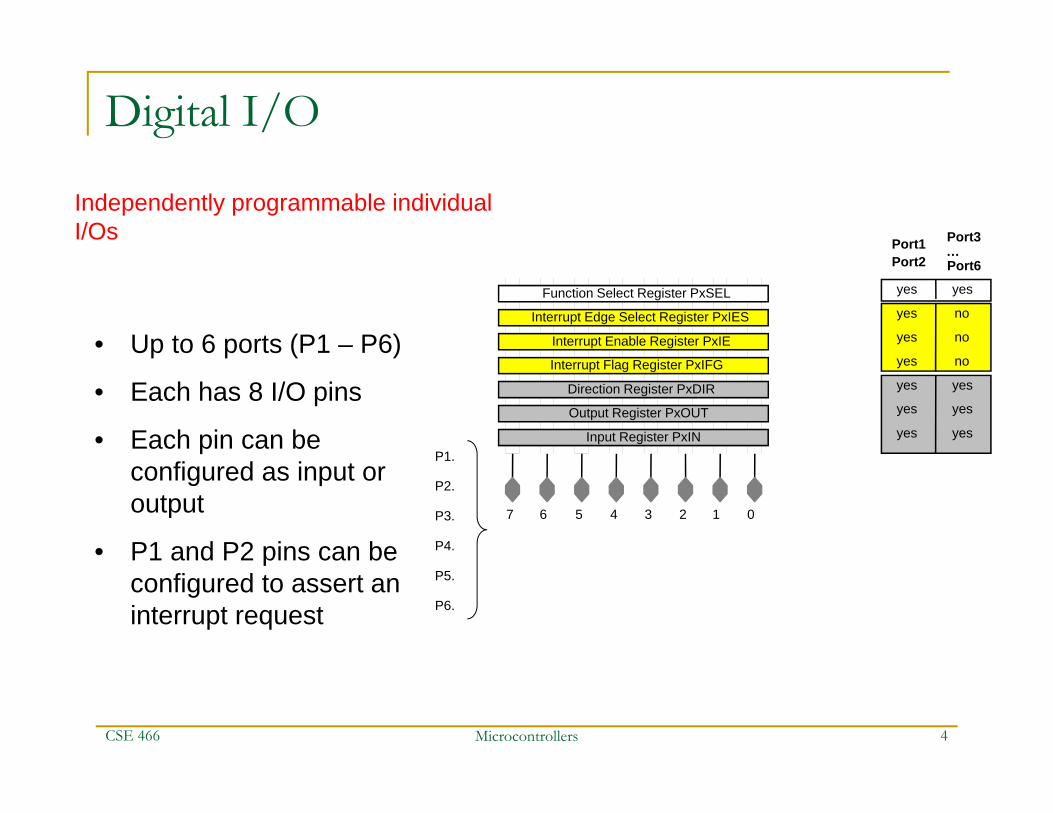
Digital I/O
Independently programmable individual I/Os
• Up to 6 ports (P1 – P6)
• Each has 8 I/O pins
• Each pin can be configured as input or output
• P1 and P2 pins can be configured to assert an interrupt request
01234567
P1.
P6.
P2.
Input Register PxIN
Output Register PxOUT
Direction Register PxDIR
Interrupt Flag Register PxIFG
Interrupt Enable Register PxIE
Interrupt Edge Select Register PxIES
Function Select Register PxSEL
P3.
P5.
Port1Port2
Port3
Port6
yes yes
yes no
yes no
yes no
yesyes
yesyes
yesyes
P4.
…
CSE 466

Microcontrollers 5
Watchdog Timer
WDT module performs a controlled system restart after a software problem occurs
• Can serve as an interval timer (generates interrupts)
• WDT Control register is password protected
• Note: Powers-up active
CSE 466
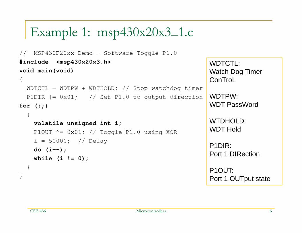
Example 1: msp430x20x3_1.c// MSP430F20xx Demo - Software Toggle P1.0#include <msp430x20x3.h>void main(void){WDTCTL = WDTPW + WDTHOLD; // Stop watchdog timerP1DIR |= 0x01; // Set P1.0 to output direction
for (;;){
volatile unsigned int i;P1OUT ^= 0x01; // Toggle P1.0 using XORi = 50000; // Delaydo (i--);while (i != 0);
}}
CSE 466 Microcontrollers 6
WDTCTL:Watch Dog Timer ConTroL
WDTPW:WDT PassWord
WTDHOLD:WDT Hold
P1DIR:Port 1 DIRection
P1OUT:Port 1 OUTput state

Example 2: msp430x20x3P1_01.c// MSP430F20xx Demo - Software Poll P1.4, Set P1.0 if P1.4 = 1// Desc: Poll P1.4 in a loop, if hi P1.0 is set, if low, P1.0 reset.// ACLK = n/a, MCLK = SMCLK = default DCO#include <msp430x20x3.h>void main(void){WDTCTL = WDTPW + WDTHOLD; // Stop watchdog timerP1DIR |= 0x01; // Set P1.0 to output directionwhile (1) // Test P1.4{
if ((0x10 & P1IN)) P1OUT |= 0x01;// if P1.4 set, set P1.0else P1OUT &= ~0x01; // else reset
}}
CSE 466 Microcontrollers 7

Microcontrollers 8
MSP430 Memory Model
CSE 466
SFR: Special Function Registers
Not presentin F2013
Microcontrollers 9
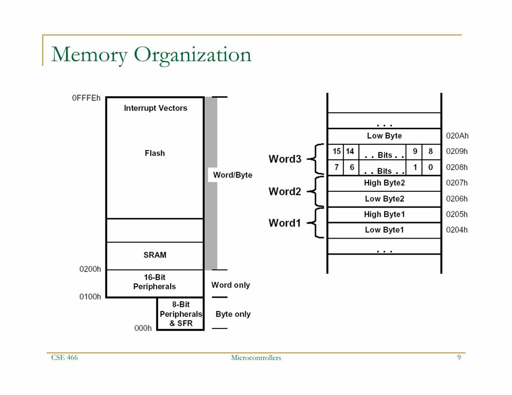
Memory Organization
CSE 466

Microcontrollers 10
MSP 430 Architecture: A Closer Look
CSE 466
Microcontrollers 11
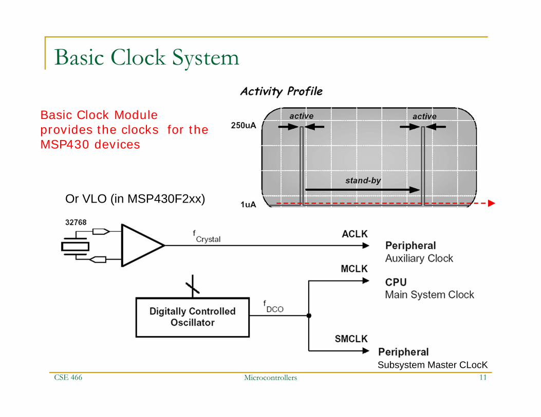
Basic Clock System
Basic Clock Moduleprovides the clocks for the MSP430 devices
CSE 466 Subsystem Master CLocK
Or VLO (in MSP430F2xx)
Microcontrollers 12
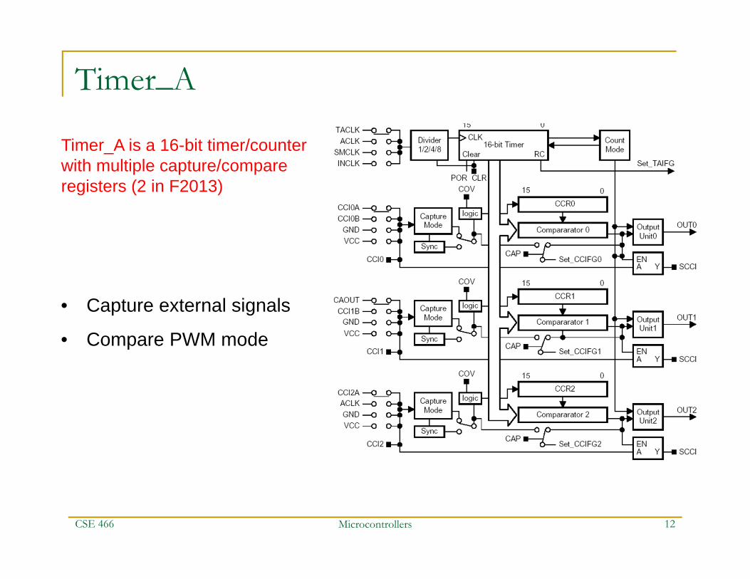
Timer_A
Timer_A is a 16-bit timer/counter with multiple capture/compare registers (2 in F2013)
• Capture external signals
• Compare PWM mode
CSE 466
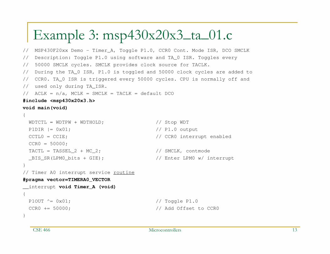
Example 3: msp430x20x3_ta_01.c// MSP430F20xx Demo - Timer_A, Toggle P1.0, CCR0 Cont. Mode ISR, DCO SMCLK// Description: Toggle P1.0 using software and TA_0 ISR. Toggles every// 50000 SMCLK cycles. SMCLK provides clock source for TACLK.// During the TA_0 ISR, P1.0 is toggled and 50000 clock cycles are added to// CCR0. TA_0 ISR is triggered every 50000 cycles. CPU is normally off and// used only during TA_ISR.// ACLK = n/a, MCLK = SMCLK = TACLK = default DCO#include <msp430x20x3.h>void main(void){
WDTCTL = WDTPW + WDTHOLD; // Stop WDTP1DIR |= 0x01; // P1.0 outputCCTL0 = CCIE; // CCR0 interrupt enabledCCR0 = 50000;TACTL = TASSEL_2 + MC_2; // SMCLK, contmode_BIS_SR(LPM0_bits + GIE); // Enter LPM0 w/ interrupt
}// Timer A0 interrupt service routine#pragma vector=TIMERA0_VECTOR__interrupt void Timer_A (void){
P1OUT ^= 0x01; // Toggle P1.0CCR0 += 50000; // Add Offset to CCR0
}
CSE 466 Microcontrollers 13
Microcontrollers 14
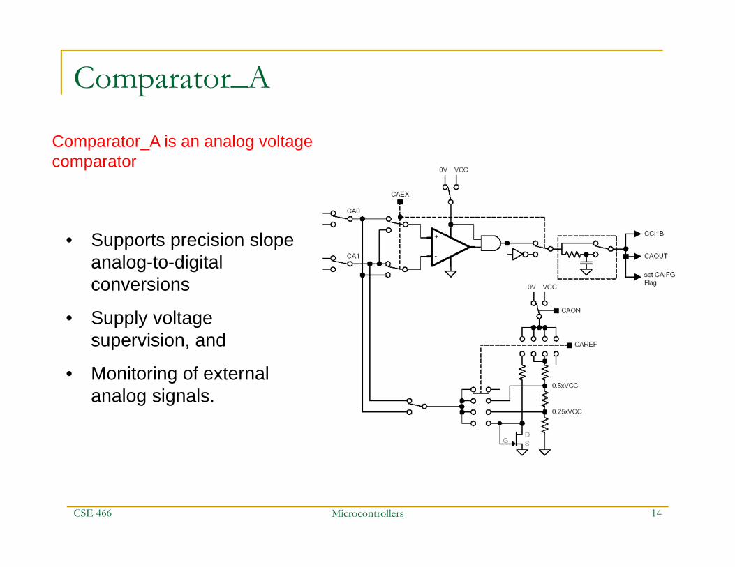
Comparator_A
Comparator_A is an analog voltage comparator
• Supports precision slope analog-to-digital conversions
• Supply voltage supervision, and
• Monitoring of external analog signals.
CSE 466

Microcontrollers 15
ADC12
High-performance 12-bit analog-to-digital converter
• More than 200 Ksamples/sec
• Programmable sample&hold
• 8 external input channels
• Internal storage
CSE 466

Microcontrollers 16
USART Serial Port
The universal synchronous/ asynchronous receive/transmit (USART) peripheral interface supports two serial modes with one hardware module
• UART or SPI (Synchronous Peripheral Interface) modes
• Double-buffered
• Baud-rate generator
CSE 466

End of lecture 2
CSE 466 Microcontrollers 17
Microcontrollers 18
MSP430 CPU Introduction RISC architecture with 27 instructions and 7 addressing modes. Orthogonal architecture with every instruction usable with every
addressing mode. 16-bit address bus allows direct access and branching throughout
entire memory range; no paging 16-bit data bus allows direct manipulation of word-wide arguments. Constant generator provides six most used immediate values and
reduces code size. Direct memory-to-memory transfers without intermediate register
holding. Word and byte addressing and instruction formats. Compact silicon 30% smaller than an ‘8051 saves power and cost
CSE 466
Microcontrollers 19
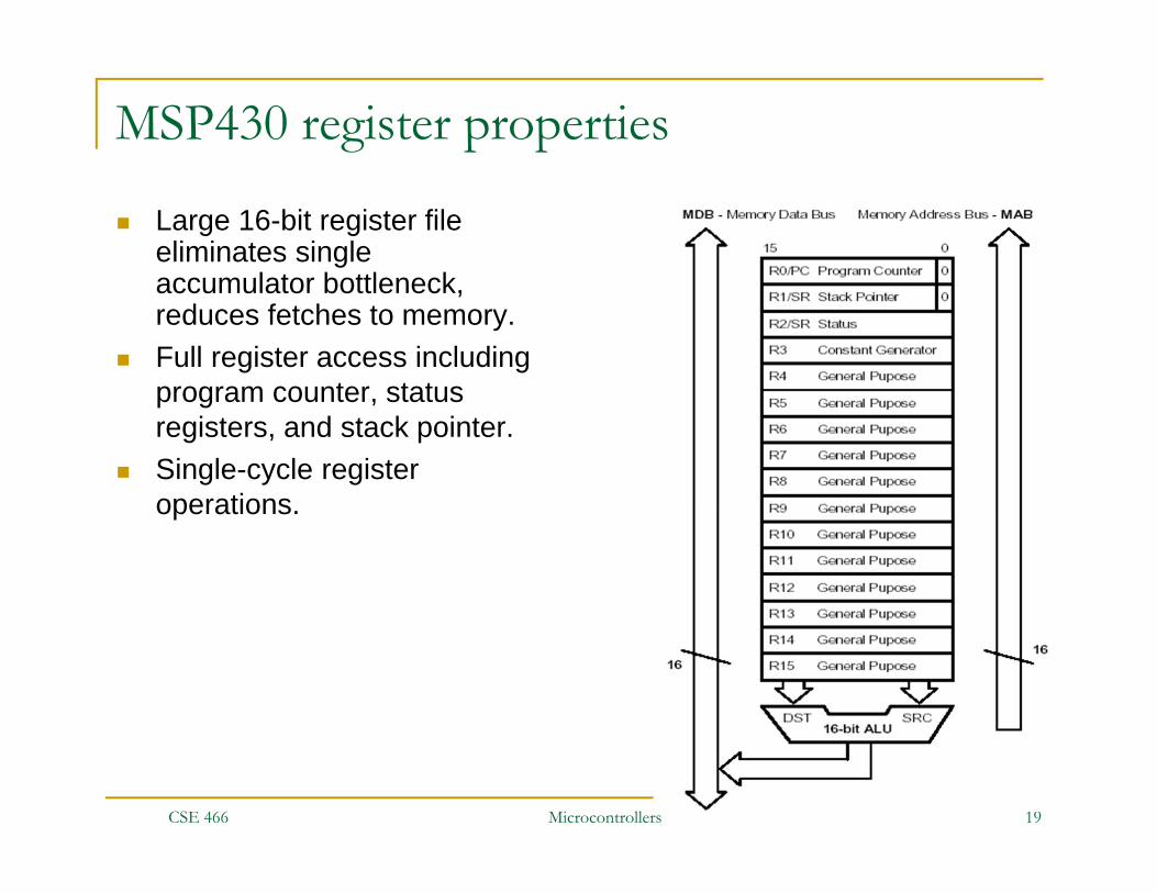
MSP430 register properties
Large 16-bit register file eliminates single accumulator bottleneck, reduces fetches to memory.
Full register access including program counter, status registers, and stack pointer.
Single-cycle register operations.
CSE 466
Microcontrollers 20
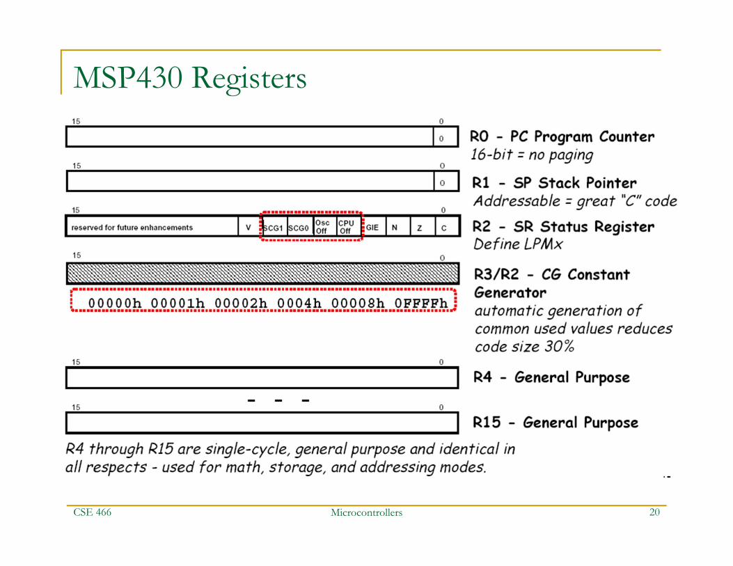
MSP430 Registers
CSE 466

Microcontrollers 21
Registers: PC (R0)
Each instruction uses an even number of bytes (2, 4, or 6)
PC is word aligned (the LSB is 0)
Format:OP SRC, DST ; NB, a lot of processors use “DST,SRC”
MOV #LABEL,PC ; Branch to address LABELMOV LABEL,PC ; Branch to address contained in LABELMOV @R14,PC ; Branch indirect, indirect R14
CSE 466

Microcontrollers 22
Registers: SP (R1) Stack pointer for return addresses of subroutines and interrupts Stack is in general purpose RAM (unlike e.g. PIC) SP is word aligned (the LSB is 0)
Pushing a single byte on the stack wastes a byte…the byte at the “wasted” location is not modified by the push
Contrast with single-byte register operations, which zero the unused byte
SP points to most recently added word (not to next free word) Starts from top of memory (0x0280 in F2013) In assembly, you must initialize the SP yourself!
Don’t try to jump in to an initialization subroutine to set up the SP…if the SP is not set up before the subroutine call, you won’t return properly from the initialization subroutine!
CSE 466

Microcontrollers 23
Registers: SP (R1)
MOV 2(SP),R6 ; Item I2 –> R6MOV R7,0(SP) ; Overwrite TOS with R7PUSH #0123h ; Put 0123h onto TOSPOP R8 ; R8 = 0123h
CSE 466
TOS: “Top Of Stack”TOS is actually the lowest address in the stack!
Highest RAM address is 0x0280 in F2013
2(SP) means 2+SPExample stack manipulations:

Microcontrollers 24
Registers: SR (R2)
C: SR(0) Carry Z: SR(1) Zero N: SR(2) Negative (==msb of result) GIE: SR(3) Global interrupt enable CPUOff: SR(4) LPM control OSCOff: SR(5) LPM control SCG0: SR(6) System Clock Generator 0…LPM control SCG1: SR(7) System Clock Generator 0…LPM control V: SR(8) signed oVerflow
CSE 466
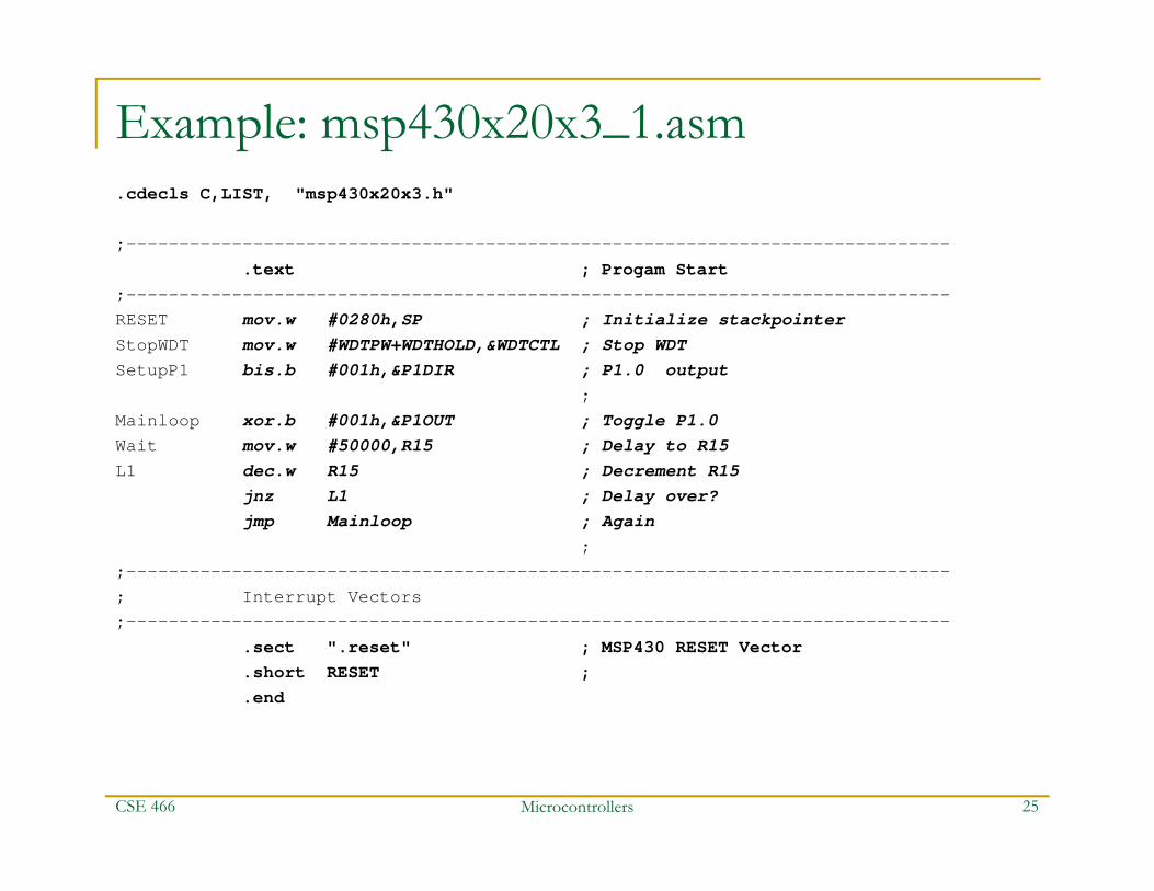
Example: msp430x20x3_1.asm.cdecls C,LIST, "msp430x20x3.h"
;------------------------------------------------------------------------------.text ; Progam Start
;------------------------------------------------------------------------------RESET mov.w #0280h,SP ; Initialize stackpointerStopWDT mov.w #WDTPW+WDTHOLD,&WDTCTL ; Stop WDTSetupP1 bis.b #001h,&P1DIR ; P1.0 output
;Mainloop xor.b #001h,&P1OUT ; Toggle P1.0Wait mov.w #50000,R15 ; Delay to R15L1 dec.w R15 ; Decrement R15
jnz L1 ; Delay over?jmp Mainloop ; Again
;;------------------------------------------------------------------------------; Interrupt Vectors;------------------------------------------------------------------------------
.sect ".reset" ; MSP430 RESET Vector
.short RESET ;
.end
CSE 466 Microcontrollers 25

Microcontrollers 26
Status bits
CSE 466
NB: in MSP430, mov operations do not affect status register
Demo interlude, including debugger!
CSE 466 Microcontrollers 27
CPE/EE 421/521 Microcomputers 28
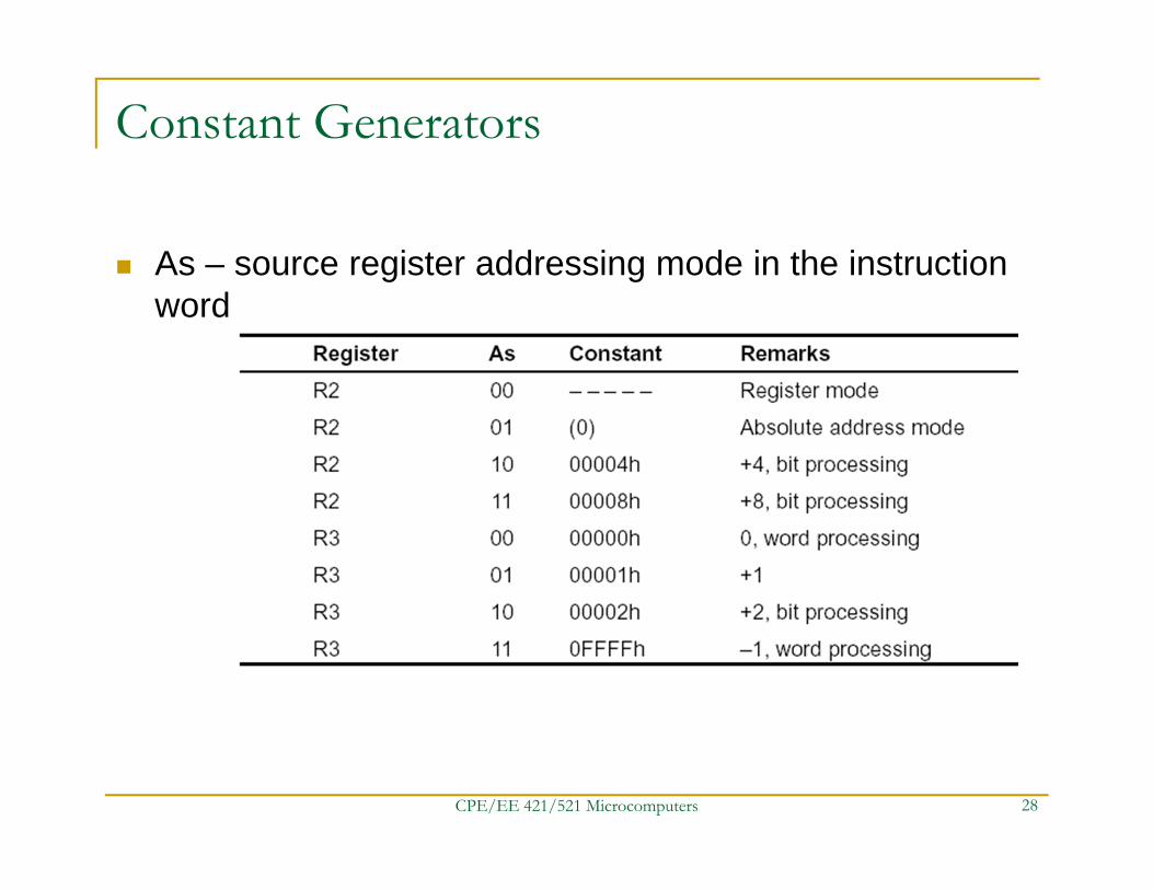
Constant Generators
As – source register addressing mode in the instruction word
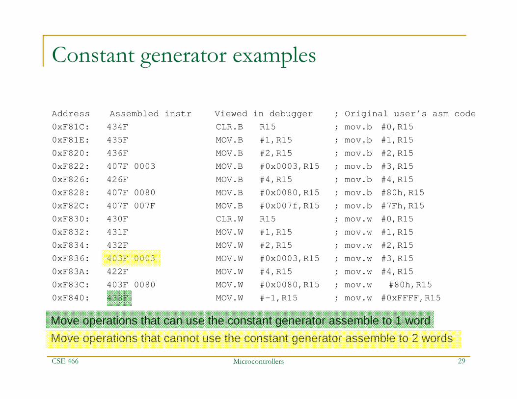
Constant generator examples
Address Assembled instr Viewed in debugger ; Original user’s asm code 0xF81C: 434F CLR.B R15 ; mov.b #0,R150xF81E: 435F MOV.B #1,R15 ; mov.b #1,R150xF820: 436F MOV.B #2,R15 ; mov.b #2,R150xF822: 407F 0003 MOV.B #0x0003,R15 ; mov.b #3,R150xF826: 426F MOV.B #4,R15 ; mov.b #4,R150xF828: 407F 0080 MOV.B #0x0080,R15 ; mov.b #80h,R150xF82C: 407F 007F MOV.B #0x007f,R15 ; mov.b #7Fh,R150xF830: 430F CLR.W R15 ; mov.w #0,R150xF832: 431F MOV.W #1,R15 ; mov.w #1,R150xF834: 432F MOV.W #2,R15 ; mov.w #2,R150xF836: 403F 0003 MOV.W #0x0003,R15 ; mov.w #3,R150xF83A: 422F MOV.W #4,R15 ; mov.w #4,R150xF83C: 403F 0080 MOV.W #0x0080,R15 ; mov.w #80h,R150xF840: 433F MOV.W #-1,R15 ; mov.w #0xFFFF,R15
CSE 466 Microcontrollers 29
Move operations that can use the constant generator assemble to 1 wordMove operations that cannot use the constant generator assemble to 2 words
Microcontrollers 30
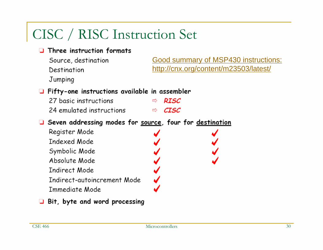
CISC / RISC Instruction Set
CSE 466
Good summary of MSP430 instructions: http://cnx.org/content/m23503/latest/
Microcontrollers 31
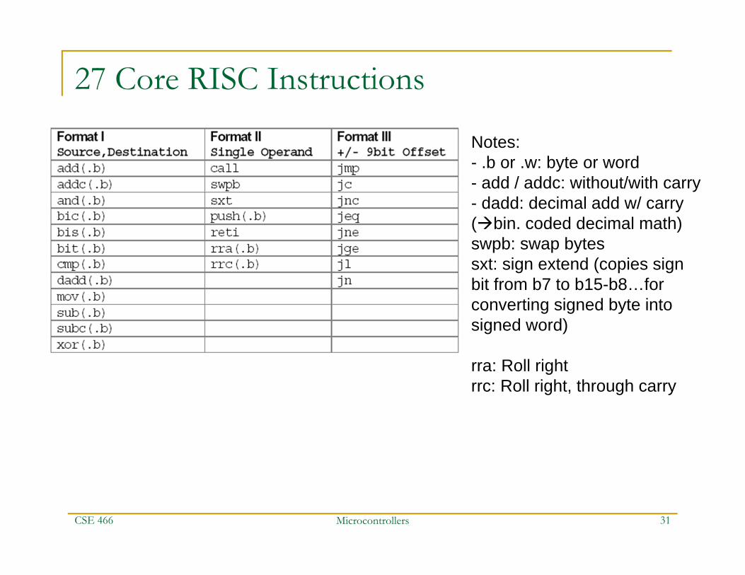
27 Core RISC Instructions
CSE 466
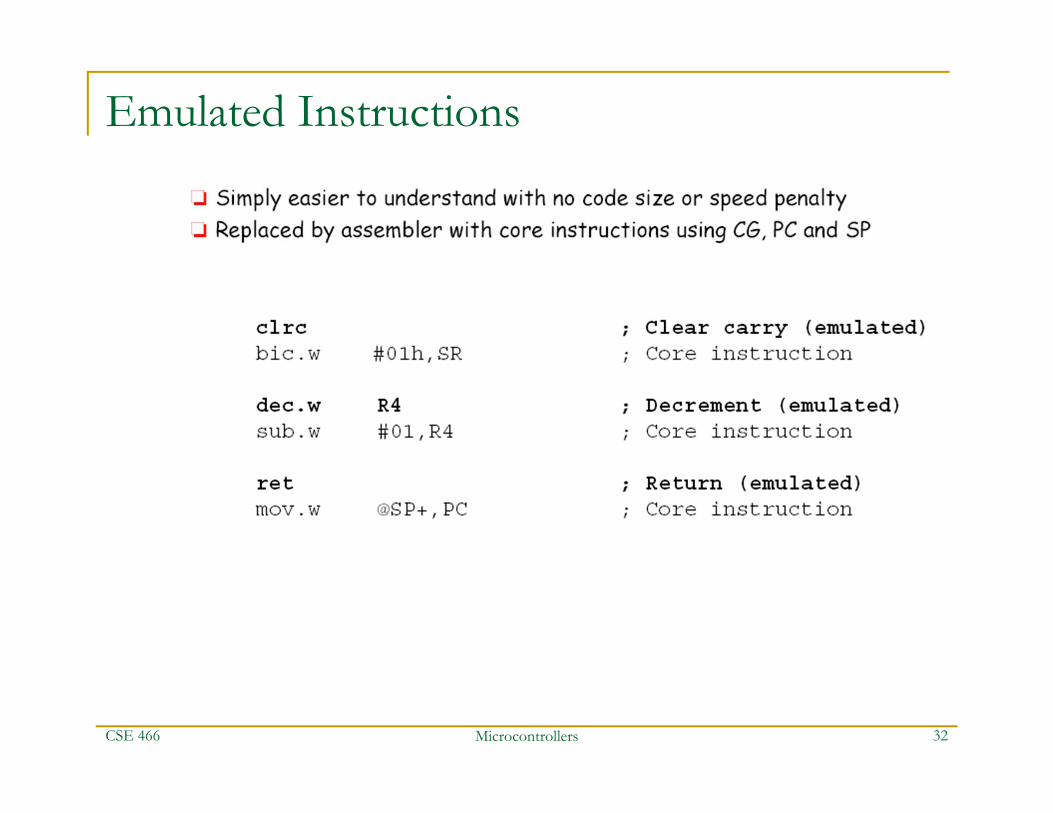
Notes:- .b or .w: byte or word- add / addc: without/with carry- dadd: decimal add w/ carry (bin. coded decimal math)swpb: swap bytessxt: sign extend (copies sign bit from b7 to b15-b8…for converting signed byte into signed word)
rra: Roll rightrrc: Roll right, through carry
Microcontrollers 32
Emulated Instructions
CSE 466
Microcontrollers 33
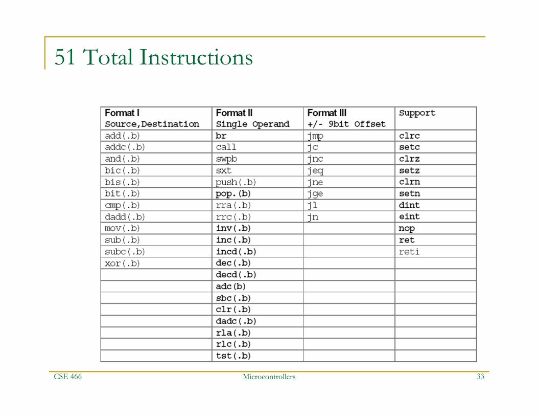
51 Total Instructions
CSE 466

Example 2: msp430x20x3_P1_01.asm;*******************************************************************************.cdecls C,LIST, "msp430x20x3.h"
;------------------------------------------------------------------------------.text ; Program Start
;------------------------------------------------------------------------------RESET mov.w #0280h,SP ; Initialize stackpointerStopWDT mov.w #WDTPW+WDTHOLD,&WDTCTL ; Stop WDTSetupP1 bis.b #001h,&P1DIR ; P1.0 outputMainloop bit.b #010h,&P1IN ; P1.4 hi/low?
jc ON ; jmp--> P1.4 is set;
OFF bic.b #001h,&P1OUT ; P1.0 = 0 / LED OFFjmp Mainloop ;
ON bis.b #001h,&P1OUT ; P1.0 = 1 / LED ONjmp Mainloop ;
;;------------------------------------------------------------------------------; Interrupt Vectors;------------------------------------------------------------------------------
.sect ".reset" ; MSP430 RESET Vector
.short RESET ;
.end
CSE 466 Microcontrollers 34
Microcontrollers 35
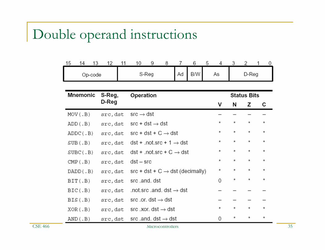
Double operand instructions
CSE 466

Microcontrollers 36
Single Operand Instruction
CSE 466

Microcontrollers 37
Jump Instructions
CSE 466
Microcontrollers 38
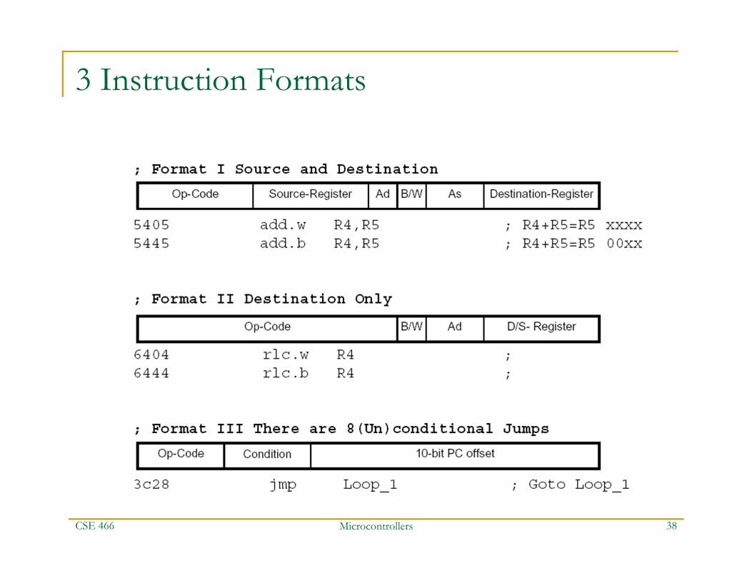
3 Instruction Formats
CSE 466
End of lecture 3
CSE 466 Microcontrollers 39

Microcontrollers 40
Addressing Modes
CSE 466

Microcontrollers 41
Register Addressing Mode
CSE 466

Microcontrollers 42
Register-Indexed Addressing Mode
CSE 466
Useful for implementing arrays…above, 100h is the base address of the source array, and the contents of R4 are the index of the source array.
Difference between C and MSP430 assembly: in assembly bytes are indexed, even if we’re dealing with an array of words of larger…in C, the index counts the items, whatever size they are
Microcontrollers 43
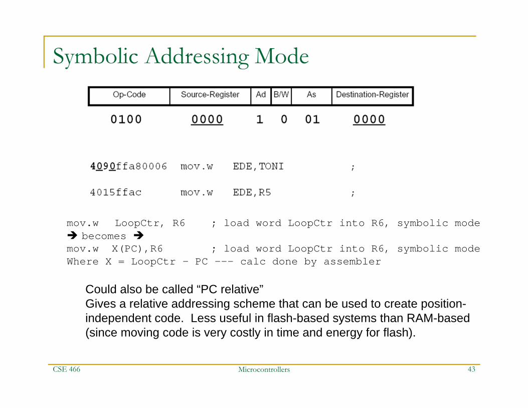
Symbolic Addressing Mode
CSE 466
Could also be called “PC relative”Gives a relative addressing scheme that can be used to create position-independent code. Less useful in flash-based systems than RAM-based(since moving code is very costly in time and energy for flash).
mov.w LoopCtr, R6 ; load word LoopCtr into R6, symbolic mode becomes mov.w X(PC),R6 ; load word LoopCtr into R6, symbolic modeWhere X = LoopCtr – PC --- calc done by assembler

Microcontrollers 44
Absolute Addressing Mode
CSE 466
mov.b &P1IN,R6 ; load byte P1IN into R6, abs mode becomes mov.b P1IN(SR),R6 ; load byte P1IN into R6, abs mode
SR returns 0 in this case…a kind of constant generator fn
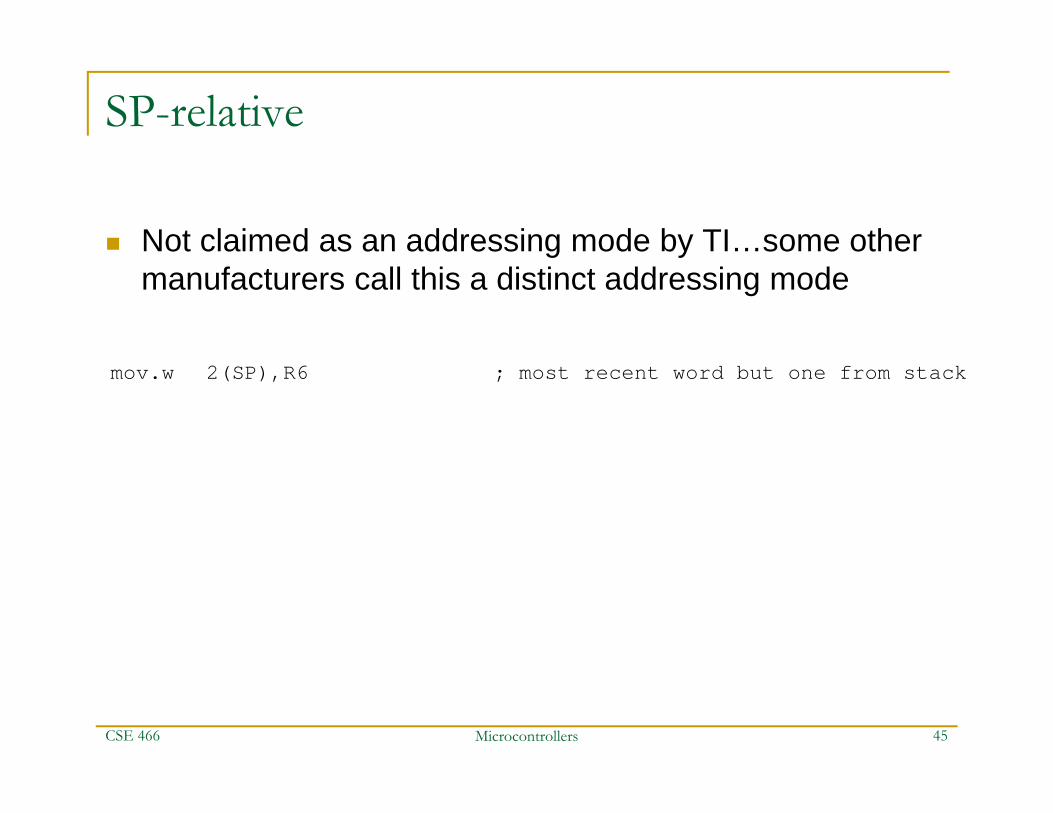
SP-relative
Not claimed as an addressing mode by TI…some other manufacturers call this a distinct addressing mode
CSE 466 Microcontrollers 45
mov.w 2(SP),R6 ; most recent word but one from stack

Microcontrollers 46
Register Indirect Addressing Mode
CSE 466
Memory at addr held inR4 is moved into R5
This mode can’t be used for destination addresses, only sourceInstead, need to use indexed addressing for destination:

Microcontrollers 47
Register Indirect Autoincrement Addressing Mode
CSE 466
Inverse operation:mov.w R6,0(R5) ; store word from R6 into addr 0+(R5)=4incd.w R5 ; R5 += 2

Microcontrollers 48
Immediate Addressing Mode
CSE 466
Equivalent tomov.w @PC+,R6 ; load immediate word 1234h into R6DW 1234h ;