bn series control device units · general data compatibility with ns series switches minimal...
TRANSCRIPT

BN series control device units
1 BN series control device units
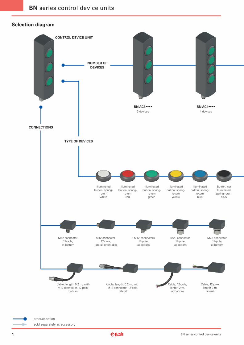
Selection diagram
NUMBER OF DEVICES
CONTROL DEVICE UNIT
CONNECTIONS
TYPE OF DEVICES
product option
sold separately as accessory
BN series control device units
2 M12 connectors, 12-pole,
at bottom
M12 connector, 12-pole,
at bottom
M12 connector, 12-pole,
lateral, orientable
M23 connector, 19-pole,
at bottom
M23 connector, 12-pole,
at bottom
Cable, length: 0.2 m, with M12 connector, 12-pole,
bottom
Cable, length: 0.2 m, with M12 connector, 12-pole,
lateral
Cable, 12-pole, length 2 m, at bottom
Cable, 12-pole, length 2 m,
lateral
Illuminated button, spring-
return white
Illuminated button, spring-
return red
Illuminated button, spring-
return green
Illuminated button, spring-
return yellow
Illuminated button, spring-
return blue
Button, not illuminated, spring-return
black
BN AC3••••3 devices
BN AC4••••4 devices

2
BN AC3ZA01
BN series control device units
Button configuration
A01 A01 configuration
A02 A02 configuration
A03 A03 configuration
... other configurations on request
Code structure Attention! The feasibility of a code number does not mean the effective availability of a product. Please contact our sales office.
Number of devices
3 3 devices
4 4 devices
6 6 devices
7 7 devices
8 8 devices
Indicator light, white
Indicator light, red
Indicator light, green
Selector switch with handle, illuminated
2 or 3 positions
Key selector switch,
2 positions
Closing cap Emergency-stop button
with rotary release
Emergency-stop button
with push-pull release
BN AC7••••7 devices
BN AC8••••8 devices
BN AC6••••6 devices

3
Electrical ratings: 24 Vdc Class 2, 0,1 AInput Supplied by 24 V dc, Class 2 Source or limited voltage limited energy, 0,096 A max. (maximum eight leds).Output 24 Vac/dc Class 2 0,25 A Pilot Duty (maximum eight actuators, with maximum twelve contacts, NO or NC or both) or 0,18 A Pilot Duty (maximum eight actuators, with maximum sixteen contacts, NO or NC or both).
Environmental ratings: Type 1
BN series control device units
Main features•Modular control device unit for 3 to 8 devices.•Can be fixed in various positions.•Flush-mounted control devices.•Compact dimensions, minimal housing width.•Numerous control devices available.
Compliance with the requirements of:Machinery Directive 2006/42/EC, Low Voltage Directive 2014/35/EU, EMC Directive 2014/30/EU, RoHS Directive 2011/65/EU.
Quality marks:
UL approval: E131787
Technical data
BN series control device units
Housing made of glass fibre reinforced technopolymer, self-extinguishing and shock-proof.Versions with integrated cable 12 x 0.14 mm2, length 2 m, other lengths from 0.5 m to 10 m on request.Versions with integrated M23 or M12 stainless steel connector.Versions with 2 integrated M12 stainless steel connectors.Versions with 0.2 m cable and M12 connector, other lengths from 0.1 … 3 m on request.Protection degree: IP65 acc. to EN 60529
General dataAmbient temperature: -25°C … +70°CFixing screws for the housing: 2xM5, tightening torque 3 NmFixing screws for turnable modules: Tightening torque of 0.8 … 1.2 NmMechanical endurance:
Spring-return button: 1 million operating cyclesEmergency stop button: 50,000 operating cyclesSelector switch: 300,000 operating cyclesKey selector switch: 50,000 operating cycles
30,000 operating cycles including removal of the key
Safety parameter B10D: 100,000 (emergency-stop button)Actuating force:
Spring-return button: 4 N min 100 N max.Emergency stop button: 20 N min 100 N max.Selector switch: 0.1 Nm min 1.5 Nm max.Key selector switch: 0.1 Nm min 1.3 Nm max.
Electrical data of the devicesRated operating voltage Ue: 24 Vdc ±10% SELVThermal current Ith: 1 ARated insulation voltage Ui: 32 Vac/dcRated impulse withstand voltage Uimp: 1.5 kVMaterial of the contacts: silver contactsContact type: Self-cleaning contacts with double interruptionUtilization category of the contact block: DC13; Ue = 24 V; Ie = 0.55 ALED supply voltage: 24 Vdc ±15%Single LED supply current: 12 mA
In compliance with standards:IEC 60947-5-1, IEC 60947-5-5, EN ISO 13850, UL 508, CSA 22.2 No.14
Installation for safety applications:Always connect the safety circuit to the NC contacts (normally closed contacts) as stated in standard EN 60947-5-1.
Actuation of the control devices from various directionsThanks to the design with turnable modules, the control device units of the BN series offer the user many different options for fixing to the machine.The orientation of the control devices can be selected inde-pendent of the fastening.With the configurations for 6, 7 and 8 devices, the upper and lower part can be oriented independent of one another. This is especially useful if it should be possible to achieve a command state from two different sides of the machine. In these cases, a single device and single wiring harness can be used, thereby saving time and money.
Features approved by ULM12 connector electrical dataMax. operating voltage: 32 Vac/dcMax. operating current: 1.5 A max.
M23 connector electrical dataMax. operating voltage: 32 Vac/dcMax. operating current: 3 A max.

4
40 mm
BN series control device units
The new modular control device units of the BN series from Pizzato Elettrica can be combined perfectly with the RFID safety switches with lock of the NS series. Machine manufacturers who already use these products thereby have the possibility to attach a control device unit directly next to the safety switch that is identical in shape and dimensions.The control device units of the BN series are available in configurations with 3 to 8 devices.The unique design with individually turnable modules allows the user to select from a number of combinations. He receives a very versatile product that is immediately ready for use.
General data
Compatibility with NS series switches Minimal dimensions
Protection against tamperingTurnable and non-detachable modules
Individually and freely configurable
Each control device unit of the BN series is supplied complete with snap-on protection caps to be applied on the holes of the fixing screws. Not only do the caps pre-vent deposits of dirt from accumu-lating and simplify cleaning, they also prevent access to the fixing screws of the device, thereby offer-ing increased protection against tampering.
During installation, the fixing modules can be turned on the top and bottom of the device to enable variable orientation of the control devices.Operation is very simple: after loosen-ing the fixing screws, the device body can be turned in steps of 90° and fixed in the desired position. Another advantage for the installer is that the fixing mod-ules cannot be detached from the device body. Disassembly of the individual parts is not necessary and there is no risk of losing parts or reassembling incorrectly.
The control device units of the BN series have the same dimensions as the RFID safety switches with lock of the NS series. When mounted directly to the side of the switch, one obtains an integrated safety device whose components are made of the same material and have identical dimensions.
One special feature of the control device units of the BN series is the slim thickness of just 40 mm.The control devices are embedded in the housing of the unit and protrude only slightly out of the front.This protects the control devices from unintended impacts, thereby increasing the service life of the devices and, at the same time, giving the devices an attractive design, making them predestined for use on modern machines in which this aspect is also given special consideration.
The control device unit is available in various configurations: for standard applications there are configurations with 3 or 4 devices, while configurations with 6, 7 or 8 devices are available for more complex applications that allow a larger number of control and signalling devices to be attached at the same location for the user.With all product configurations, a number of devices can be installed that can also be illuminated via LEDs integrated in the device.

5
BN AC3ZA01
BN AC3ZA02
BN AC3ZA03
LED
LED
LED
/
LED
LED
/
LED
LED
/
1 4
2 3
1 5
6 3
1 7
12 3
1 4
2 3
5 6
12 3
8 910 11
1 4
2 3
1 5
6 3
8 910 11
1
4
5
7
8
9
10
11
2
6
12
30 V
1
4
5
6
7
8
9
10
11
12
2
30 V
1
4
5
7
8
9
10
11
2
6
12
30 V
BN series control device units
BN series control device units
Examples of available configurations
For pin assignments of the connectors, see page 9
Description Colour Diagram
Dev
ice
1 Illuminated button, spring-return
1NO white
Dev
ice
2 Illuminated button, spring-return
1NO blue
Dev
ice
3 Illuminated button, spring-return
1NO yellow
Con
nect
or
M12, 12-pole, at bottom /
Connections
Connections
ConnectionsDescription Colour Diagram
Dev
ice
1 Illuminated button, spring-return
1NO white
Dev
ice
2 Illuminated button, spring-return
1NO blue
Dev
ice
3 Emergency-stop button with rotary release
2NC red
Con
nect
or
M12, 12-pole, at bottom /
Description Colour Diagram
Dev
ice
1 Illuminated button, spring-return
1NO white
Dev
ice
2 Illuminated button, spring-return
1NO yellow
Dev
ice
3 Emergency-stop button with rotary release
2NC red
Con
nect
or
M12, 12-pole, at bottom /

6
BN AC4ZA01
BN AC4ZA02
BN AC4ZA03
LED
LED
LED
/
LED
LED
LED
/
LED
LED
/
1 4
2 3
1 5
6 3
1 7
8 3
1 9
1 4
2 3
1 5
6 3
1 7
12 3
8 9
10 11
8 9
10 11
1 4
2 3
1 5
12 3
0 V
1
4
5
7
9
10
11
2
6
8
12
3
0 V
1
4
5
7
8
9
10
11
2
6
12
3
0 V
1
4
5
7
8
9
10
11
2
6
12
3
BN series control device units
For pin assignments of the connectors, see page 9
Description Colour Diagram
Dev
ice
1 Illuminated button, spring-return
1NO green
Dev
ice
2 Illuminated button, spring-return
1NO red
Dev
ice
3 Illuminated button, spring-return
1NO whiteD
evic
e 4 Two-position key
selector switch 1NO black
Con
nect
or
M12, 12-pole, at bottom
Connections
Connections
Connections
Description Colour Diagram
Dev
ice
1 Illuminated button, spring-return
1NO white
Dev
ice
2 Illuminated button, spring-return
1NO blue
Dev
ice
3 Illuminated button, spring-return
1NO yellow
Dev
ice
4 Emergency-stop button with rotary release
2NC red
Con
nect
or
M12, 12-pole, at bottom /
Description Colour Diagram
Dev
ice
1 Illuminated button, spring-return
1NO white
Dev
ice
2
Spring-return button1NO black
Dev
ice
3
Indicator lightgreen
Dev
ice
4 Emergency-stop button with rotary release
2NC red
Con
nect
or
M23, 12-pole, at bottom

7
BN AC6ZA01
BN AC6ZA02
LED
LED
LED
LED
LED
LED
LED
LED
LED
LED
A1 A4
A2 A3
A1 A5
A6 A3
A1 A7
A12 A3
B2 B3
B6 B3
B8 B9B10 B11
10 1113 14
6 4
1 19
6 5
2 19
6 8
7 19
12 19
16 19
0 V
A1
A4
A5
A7
A8
A9
A10
A11
A2
A6
A12
A3
B1
B4
B5
B7
B8
B9
B10
B11
B2
B6
B12
B30 V
6
4
5
8
1
2
7
15
9
3
17
18
10
11
13
14
12
16
190 V
BN series control device units
BN series control device units
For pin assignments of the connectors, see page 9
Description Colour Diagram
Dev
ice
1 Illuminated button, spring-return
1NO white
Dev
ice
2 Illuminated button, spring-return
1NO blue
Dev
ice
3 Illuminated button, spring-return
1NO yellowD
evic
e 4
Indicator lightgreen
Dev
ice
5
Indicator lightwhite
Dev
ice
6 Emergency-stop button with rotary release
2NC red
Con
nect
or
Two M12, 12-pole, at bottom /
Description Colour Diagram
Dev
ice
1 Illuminated button, spring-return
1NO white
Dev
ice
2 Illuminated button, spring-return
1NO blue
Dev
ice
3 Illuminated button, spring-return
1NO yellow
Dev
ice
4
Indicator lightgreen
Dev
ice
5
Indicator lightwhite
Dev
ice
6 Emergency-stop button with rotary release
2NC red
Con
nect
or
M23, 19-pole, at bottom /
Connections
Connections

8
BN AC7ZA01
BN AC8ZA01
LED
LED
LED
LED
LED
LED
LED
LED
LED
LED
LED
A1 A4
A1 A5
A6 A3
A12 A3
B2 B3
B6 B3
B12 B3
B8 B9B10 B11
B1 B5
B1 B7
B1 B4
A8 A3
A1 A9
A12 A3
A1 A4
A2 A3
A6 A3
B8 B9B10 B11
B1 B5
B12 B3
B1 B7
B2 B3
B1 B4
0 V
A1
A4
A5
A7
A8
A9
A10
A11
A2
A6
A12
A3
B1
B4
B5
B7
B8
B9
B10
B11
B2
B6
B12
B30 V
0 V
A1
A4
A5
A7
A9
A10
A11
A2
A6
A8
A12
A3
B1
B4
B5
B7
B8
B9
B10
B11
B2
B6
B12
B30 V
BN series control device units
For pin assignments of the connectors, see page 9
Description Colour Diagram
Dev
ice
1 Two-position key selector switch
1NO black
Dev
ice
2 Illuminated selector switch with handle with
two positions1NO black
Dev
ice
3
Indicator lightgreen
Dev
ice
4 Illuminated button, spring-return
1NO whiteD
evic
e 5 Illuminated button,
spring-return1NO blue
Dev
ice
6 Illuminated button, spring-return
1NO yellow
Dev
ice
7 Emergency-stop button with rotary release
2NC red
Con
nect
or
Two M12, 12-pole, at bottom /
Description Colour Diagram
Dev
ice
1 Illuminated selector switch with handle with
two positions1NO black
Dev
ice
2
Indicator lightred
Dev
ice
3
Indicator lightgreen
Dev
ice
4 Illuminated button, spring-return
1NO yellow
Dev
ice
5 Illuminated button, spring-return
1NO white
Dev
ice
6
Spring-return button1NO black
Dev
ice
7 Illuminated button, spring-return
1NO blue
Dev
ice
8 Emergency-stop button with rotary release
2NC red
Con
nect
or
Two M12, 12-pole, at bottom /
Connections
Connections

9
1
2
3
4 56
7
8910
11
12
12
3
456
78
9
1011 12
13
1415
16
1718
19
A1
A2
A3
A4 A5A6
A7
A8A9A10
A11
A12
B1
B2
B3
B4 B5B6
B7
B8B9B10
B11
B12
A
B
BN series control device units
BN series control device units
Available integrated devices
Electrical connections
Description Colour ArticleCombinable
with contacts
Protrusion (x) mm
Illuminated button, spring-return
White Red Green Yellow Blue
VN NG-AC26005VN NG-AC26001VN NG-AC26003VN NG-AC26002VN NG-AC26004
1NO2NO
1NO+1NC3
Non-illuminated button, spring-return Black VN NG-AC260071NO2NO
1NO+1NC3
Indicator light White Red Green
VN NG-AC26064VN NG-AC26060VN NG-AC26062
/ 2.7
Emergency-stop button acc. to. EN ISO 13850
2NC 26.4Rotary releasePush-pull release
Red Red
VN NG-AC26052VN NG-AC26055
Illuminated selector switch with handle, with transparent lens for LED
1NO2NO
1NO+1NC16.8 Black VN NG-AC26033
Black VN NG-AC26034
Key selector switch, 2 positions1NO2NO
1NO+1NC
39 (a)14 (b) Black VN NG-AC26040
Black VN NG-AC26043
Closing cap Black VN NG-AC26090 / 0
Fixing key Black VN NG-AC26080 / /
Legend: Maintained Spring-return Key extraction position (a) with key (b) without key
M12 connector, 12-pole Two M12 connectors, 12-pole Cable
M23 connector, 12-pole M23 connector, 19-pole
Pin No. Cable colour
1 brown
2 blue
3 white
4 green
5 pink
6 yellow
Pin No. Cable colour
7 black
8 grey
9 red
10 purple
11 grey-pink
12 red-blue

10
40
191
,2
159
,4
25
57,
3 3
8,8
6,8
5,3
47,5
47,5
40
28,6
x
x
40
191
,2
159
,4
25
57,
3 3
8,8
6,8
5,3
31,7
31,7
31,7
40
310
,3
342
,1
25
38,
8 5
7,3
6,8
5,3
55,
8 4
7,5
47,
5 4
7,5
47,
5
40
310
,3
342
,1
25
38,
8 5
7,3
6,8
5,3
55,
8 3
1,7
31,
7 3
1,7
47,
5 4
7,5
40
310
,3
342
,1
25
38,
8 5
7,3
6,8
5,3
55,
8 3
1,7
31,
7 3
1,7
31,
7 3
1,7
31,
7
x
28
,6
x
40
11,
9
M12x1 18
13,8
M12
x1
M12x1
12,
8
M23x1
19,
5
BN AC6•••• BN AC7•••• BN AC8••••
BN AC3•••• BN AC4••••
BN series control device units
The 2D and 3D files are available at www.pizzato.com
Dimensional drawings
All values in the drawings are in mm
M12 connector, at bottom
M12 connector, lateral
Two M12 connectors, at bottom
M23 connector, at bottom
Output type

P A S S I O N F O R Q U A L I T Y
ZE FGL28A20-ENG
Pizzato Elettrica s.r.l. via Torino, 1 - 36063 Marostica (VI) ItalyPhone: +39 0424 470 930E-mail: [email protected]
Website: www.pizzato.com
General Catalogue Detection
General Catalogue HMI
General Catalogue Safety
Lift General Catalogue
Websitewww.pizzato.com
Any information or application example, connection diagrams included, described in this document are to be intended as purely descriptive. The choice and application of the products in conformity with the standards, in order to avoid damage to persons or goods, is the user’s responsibility. The drawings and data contained in this document are not binding and we reserve the right, in order to improve the quality of our products, to modify them at any time without prior notice. All rights to the contents of this publication are reserved in accordance with current legislation on the protection of intellectual property. The reproduction, publication, distribution and modification, total or partial, of all or part of the original material contained therein (including, but not limited to, texts, images, graphics), whether on paper or in electronic form, are expressly prohibited without written permission from Pizzato Elettrica Srl. All rights reserved. © 2020 Copyright Pizzato Elettrica.