boctlklht collection s
TRANSCRIPT

BOCtlKlHT COLLECTION s ~
OAK RIDGE NATIONAL LABORATORYoperated by
UNION CARBIDE CORPORATION
NUCLEAR DIVISION
for the
U.S. ATOMIC ENERGY COMMISSION
ORNL- TM-1906
IN- AND EX-REACTOR STRESS-RUPTURE PROPERTIES
OF HASTELLOY N TUBING
H. E. McCoy, Jr.J. R. Weir, Jr.
OAK RIDGE NATIONAL LABORATORY
CENTRAL RESEARCH LIBRARY
DOCUMENT COLLECTION
LIBRARY LOAN CORYDO NOT TRANSFER TO ANOTHER PERSON
If you wish someone else to see this
document, send in name with documentand the library will arrange a loan.
) C N-796S3 3-67.
NOTICE This document contains information of a preliminary natureand was prepared primarily for internal use at the Oak Ridge NationalLaboratory. It is subject to revision or correction and therefore doesnot represent a final report.

LEGAL NOTICE
This report was prepared as an account of Government sponsored work. Neither the United States,
nor the Commission, nor any person acting on behalf of the Commission;
A. Makes any warranty or representation, expressed or implied, with respect to the accuracy,
completeness, or usefulness of the information contained in this report, or that the use of
any information, apparatus, method, or process disclosed in this report may not infringe
privately owned rights; or
B. Assumes any liabilities with respect to the use of, or for damages resulting from the use of
any information, apparatus, method, or process disclosed in this report.
As used in the above, "person acting on behalf of the Commission" includes ony employee or
contractor of the Commi ssion, or employee of such contractor, to the extent that such employee
or contractor of the Commission, or employee of such contractor prepares, disseminates, or
provides access to, any information pursuant to his employment or contract with the Commission,
or his employment with such contractor.

ORNL-TM-1906
Contract No. W-7405-eng-26
METALS AND CERAMICS DIVISION
IN- AND EX-REACTOR STRESS-RUPTURE PROPERTIES
OF HASTELLOY N TUBING
H. E. McCoy, Jr.. and J. R. Weir, Jr.
SEPTEMBER 1967
OAK RIDGE NATIONAL LABORATORY
Oak Ridge, Tennesseeoperated by
UNION CARBIDE CORPORATION
for the
U.S. ATOMIC ENERGY COMMISSION
LOCKHEED MARTIN ENERGY RESEARCH LIBRARIES
3 ^5b DS13m? 3

*w.MwajwmMm

ill
CONTENTS
Page
Abstract 1
Introduction 1
Experimental Details 3
Test Materials 3
Test Specimens 5
Testing Techniques 5
Experimental Results 10
Discussion of Results 21
Summary and Conclusions 24-
Acknowledgments 24

IN- AND EX-REACTOR STRESS-RUPTURE PROPERTIES
OF RASTELLOY N TUBING
H. E. McCoy, Jr. and J. R. Weir, Jr.
ABSTRACT
The stress-rupture properties of two heats of
Hastelloy N tubing have been determined at 760°C in-and ex-reactor. Irradiation reduced the rupture life
and the rupture strain, but no effects on the creeprate were detectable. Small variations in behavior
of tubular specimens tested during irradiation and
small rod specimens tested after irradiation areexplained on the basis of differences in stress
states and sizes of test sections. The effects of
irradiation are rationalized on the basis of the
behavior of helium which occurs in the metal as a
result of the thermal 10B(n,a) transformation.
INTRODUCTION
Numerous cases have been reported where the high-temperature mechan
ical properties of nickel- and iron-base alloys deteriorated under neutron
irradiation.1-9 This deterioration manifests itself as both a reduction
•'•D. R. Harries, "Neutron Irradiation Embrittlement of AusteniticStainless Steels and Nickel Base Alloys," J. Brit. Nucl. Energy Soc. 5,74 (1966).
2G. H. Broomfield, D. R. Harries, and A. C. Roberts, "Neutron Irradiation Effects in Austenitic Stainless Steels and a Nimonic Alloy,"J. Iron Steel Inst. (London) 203, 502 (1965).
3N. A. Hughes and J. Caley, J. Nucl. Mater. 10, 60 (1963).
4F. C. Robertshaw et al., Am. Soc. Testing Mater. Spec. Tech. Publ.341, 372 (1963).
5N. E. Hinkle, Am. Soc. Testing Mater. Spec. Tech. Publ. 341, 344(1963).
6P.C.L. Pfeil and D. R. Harries, "Effects of Irradiation in AusteniticSteels and Other High-Temperature Alloys," Am. Soc. Testing Mater. Spec.Tech. Publ. 380, 202 (1965).
7W. R. Martin and J. R. Weir, "The Effect of Irradiation Temperature

in the creep-rupture life and in the rupture ductility. This effect has
been correlated with the thermal neutron dose and has been attributed to
the helium produced by the transmutation of 10B to 7Li and ^He.6'9'10
However, the sensitivity of different materials to helium produced by
this process varies greatly1 and our present state of understanding of
this problem necessitates that we study each material individually.
We have studied Hastelloy N, an alloy developed at Oak Ridge National
Laboratory specifically for use with molten fluoride salts.11 It is nickel
base, solid solution strengthened with about 16$ Mo, and contains 7$ Cr
for moderate oxidation resistance. However, this alloy has become a
candidate material for use in several other reactors and we are attempting
to learn as much as possible about this material in nuclear environments.
Recent studies have shown that the mechanical properties of this material
are indeed altered by irradiation.12-'13
In this study we compared the in- and ex-reactor properties of two
vacuum-melted heats of Hastelloy N tubing at 760°C. The testing techniques
used in this program will be described and the resulting test data pre
sented. These data will be compared with those obtained for the same
material in uniaxial postirradiation stress-rupture tests.
on the Post-Irradiation Stress-Strain Behavior of Stainless Steel,"Am. Soc. Testing Mater. Spec. Tech. Publ. 380, 251 (1965).
8J. T. Venard and J. R. Weir, "In-Reactor Stress-Rupture Propertiesof a 20 Cr-25 Ni Columbium-Stabilized Stainless Steel," Am. Soc. TestingMater. Spec. Tech. Publ. 380, 269 (1965).
9P.C.L. Pfeil, P. J. Barton, D. R. Arkell, Trans. Am. Nucl. Soc. 8,120 (1965). =
10P.R.B. Higgins and A. C. Roberts, Nature 206, 1249 (1965).
1:LW. D. Manly et al. , "Metallurgical Problems in Molten FluorideSystems," Progress in Nuclear Energy, 2 (IV), Technology, Engineering, andSafety, pp. 164-79, Pergamon Press (1960).
12W. R. Martin and J. R. Weir, "Effect of Elevated Temperature Irradiation on the Strength and Ductility of the Nickel-Base Alloy,Hastelloy N," Nucl. Appl. 1(2), 160-67 (1965).
13W. R. Martin and J. R. Weir, "Postirradiation Creep and StressRupture of Hastelloy N," Nucl. Appl. 3, 167 (1967).
.^t^^:a^.;:ww^

EXPERIMENTAL DETAILS
Test Materials
The two lots of material used in this study were 10,000 lb vacuum-
melted heats obtained from Allvac Metals Company. This material was con
verted to tubing by Superior Tube and had a nominal inner diameter of
0.540 in. Heat 5911 was initially fabricated with a 0.015 in. wall, but
the same material was redrawn (designated 5911R) to obtain a 0.010 in.
wall. Heat 281-4-0143 was fabricated into tubing with a 0.010 in. wall.
The working schedule used to manufacture the tubing is proprietary and
details are not available. The chemical analysis of the fabricated mate
rial is given in Table 1. A typical cross section of the as-received
tubing (Heat 281-4-0143) is shown in Fig. 1. This tubing was coated for
a specific application. Neither the coating composition nor the technique
for its application to the metal can be made available, but temperatures
as high as 1150°C were encountered in the processing. The microstructure
Table 1. Chemical Analysis of Test Material
Content, wt $
ElementHeat Number Heat Number
281-4-0143 5911
Fe 0.28 0.03
Cr 7.00 6.14
Mo 16.88 17.01
Ni Bal Bal
C 0.05 0.056
Mn 0.50 0.21
B 0.0006 0.0010
S 0.009 0.002
P 0.002 0.002
Si 0.28 0.05
Cu 0.03 <0.01
Co 0.01 0.04
Al 0.20 0.15
Ti 0.04 0.067
W 0.01 0.01
0 0.0006 0.0014
N 0.0025 <0.0005
H 0.0004

PHMHHqpaBw*j^^HM^^^^^^^^^^^^^^^^^^^^^^^^^^^^^^^^
* * • * * - *• * *
, ™( _ % « (j •• « ' /'* •* (,
V I- *x * •• i fc #* " *tv* -. ^m •* * * * : •
*• (fe ••'!. . If ^
> ._ • ..".»• -
J • • • • • , , : ". . '/ •-:' * t.
O" *• * * •* •
• « % • - •N i -' M* * • 5 • ' • • • , .j 44
* . • - •"<•.•»•.. „ '.
* • •.- ., $s • ,» • . - , i "« —„ ^ j; - 5 # # * ?* •**, ! * ° ' ' i • * •
r » w S -' % * . * .* * «• ^ • « i * - # • *%' ; < - \ * ' fc
Ot *^ ^ • * €? * * o * * * . *
* * * Cf ._• . h. « * ; O *, *, *
_,""•*'" .' © *,"'* ' »'' •"*** « '"•,♦- » <*•
' O -- ' *. w *» #*
* ' * : v * t ' 4 . * .*
.
jf" <j a • • » • 4 * • ^ ** . * * » * * • . *
^ . * * •• — *«
»•»*».., •* " ° °" e>" * • - *•* «
, * • * * '• . .' • if- . * '• . '. •. . » 4
* • ' • -* * i ••• % 1?" rf» >
« *' £
Y-73II5 n
•6- ,
Fig. 1. Photomicrographs of As-Received Hastelloy N Tubing-Heat281-4-0143. Etchant: glyceria regia.

of the tubing before it was tested is shown in Fig. 2. Because of the
brittle nature of the coating, it probably exerted little influence on
the properties of the tubing.
Test Specimens
A drawing of the test specimens used in this study is shown in Fig. 3.
The assemblies were prepared by Atomics International(Al) and shipped to
ORNL for testing.
Testing Techniques
The apparatus used in ex-reactor tube burst tests is shown schemat
ically in Fig. 4. Because of the relatively weak welds at both ends of
the tubes, only the center 3 in. section was heated. The furnace con
sisted of three 1 in. zones with a thermocouple located on the specimen
at the center of each zone for monitoring the temperature. A single pro
portioning controller was used with three variable power supplies for
controlling the temperature. The controller received its signal from
the thermocouple on the center zone and the variable power supplies were
adjusted to obtain a uniform temperature over nearly the entire center
3 in. of the specimen. The specimens were pressured with argon and the
external environment was air. After the pressure was adjusted manually,
the specimen was isolated from the gas supply. Failure was detected by
a reduction in the system pressure. This pressure change actuated a
switch that cut off a timer. Thus, failure was detected when the first
crack penetrated the tube wall.
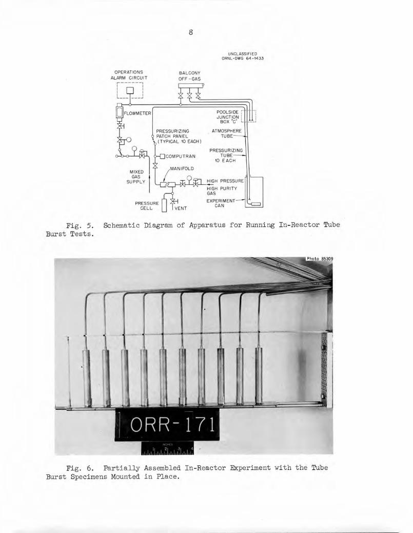
The in-reactor experiments were run in a similar fashion although
the equipment was somewhat more complicated. Figure 5 shows a schematic
diagram of the test equipment. The purge gas in these experiments was
He—1 vol $02- An experiment in two stages of completion is shown in
Figs. 6 and 7. The entire experiment is built on the framework shown
in Fig. 6. The sides of the can are welded on to obtain an integral unit
that can be immersed in the poolside of the ORR. The furnaces on these
specimens are similar to those used ex-reactor, the primary difference

Fig. 2. Photomicrographs of Processed Hastelloy N Tubing-Heat281-4-0143. Etchant: glyceria regia.

0.561-in.
DIAM
-4.500 in.
ORNL-DWG 67-4935
HASTELLOY N
-CHROME LAYER
CERAMIC BARRIER
304 STAINLESS STEEL TUBE
1/8-in. OD xQ.031-in. WALL—^
Fig. 3. Schematic Drawing of Test Specimen.
PRESSURERELEASE
SPECIMEN-
FURNACE
PRESSURESWITCH
TIMER
ORNL-DWG 67-4934
HXhPRESSURE
SOURCE
Fig. 4.Burst Tests.
Schematic Diagram of Apparatus Used for Ex-Reactor Tube
OPERATIONS
ALARM CIRCUIT
8
BALCONY
OFF-GAS
PRESSURIZING
PATCH PANEL
,(TYPICAL 10 EACH)
UNCLASSIFIED
ORNL-DWG 64-1433
POOLSIDE rJUNCTION
BOX "C" <•
ATMOSPHERE
TUBE
PRESSURIZING
TUBE •
10 EACH
HIGH PRESSURE
HIGH PURITY
GAS
EXPERIMENT- 'CAN
Fig. 5. Schematic Diagram of Apparatus for Running In-Reactor TubeBurst Tests.
Photo 85309
ORR-171
Fig. 6. Partially Assembled In-Reactor Experiment with the TubeBurst Specimens Mounted in Place.

Photo 35595
Fig. 7. In-Reactor Tube Burst Experiment Assembled Except forOutside Container.
being that each zone has a separate controller. The heaters are only
sufficient to maintain the test temperature (760°C) while the reactor is
in operation.
The three in-reactor experiments which were run in this series of
tests utilized positions P-5 and P-6 in the ORR poolside. Both positions
have very similar flux levels. Cobalt-doped type 302 stainless steel
monitors were used. The thermal flux was obtained from the 59Co(n,y) Co
reaction and the fast flux (> 4 Mev) was obtained from the 54Fe(n,p)54Mn
transmutation. The average values over the length of the test specimens
were 4 x 10¹³ neutrons cm-2 sec-1 thermal and 3 x 10¹² neutrons cm- sec
> 4 Mev.
The tubes were measured with a profilometer at AI before and after
testing. The ex-reactor specimens were measured at ORNL with a microm
eter and the in-reactor specimens were measured with an optical com
parator. The techniques used by both installations were in reasonably
good agreement, but the ORNL measurements have been used in all graphs.
The tubes were somewhat oval before testing and this made it difficult

10
to obtain accurate measurements of strain at the strains of 1$ or less.
The tangential stresses were calculated from the standard thin-wall
formula
= ?1°Q 2t (1)
where
aQ = tangential stress,
P = internal gas pressure,
d = outside diameter, and
t = wall thickness.
The wall thickness, t, is probably the largest source of error in this
calculation since it varied by up to 0.0002 in. (±2$).
EXPERIMENTAL RESULTS
The test results obtained on the three lots of material are summarized
in Tables 2 and 3. These same data are plotted in Fig. 8 as the logarithm
of the tangential stress (a ) versus the rupture life. Within the accuracy
of the data, there do not seem to be any differences between the lots of
material. Hence, we can consider the data as two sets — irradiated and
unirradiated. The large effects of small doses on the rupture life are
somewhat surprising. For example, in test 5034R where the stress was
26,000 psi there was a reduction in rupture life of about an order of
magnitude although the dose at failure was only 7 X 10¹⁷ neutrons/cm2.
The bulk helium content in specimen 5034R (Table 3) at the time of its
failure was only about 35 ppb. The irradiated and unirradiated curves
are approximately parallel.
The tangential rupture strains are compared in Fig. 9 as a function
of rupture life. Most of the unirradiated specimens have fracture strains
from 7 to 10$ although there are a few with strains as low as 4 to 5$.
The irradiated specimens exhibit tangential strains from a few tenths of
a percent to about 2$. The trend seems to be that of increasing fracture
strain with increasing rupture life (or decreasing stress). There are
two points for irradiated specimens that appear to be anomalous.

cy
n>rY
n>p
^a>
bM
rn
oV
O>
rid
-o
Hc
•>p
.
Hj
r+
413
-.
Phi
(J
r+
P-
PB
hi (DP
Mhi
V-
•O
Q OH
B(1
)
PP
S*
C+
-
H-
<?
3O
nO
(0
o
^O
en
•
r+
fD s
OU
lUiU
lUiU
iVj-
iUiU
lIV
)vD
vO
\DM
Dv
Ov
Ov
Ov
D\O
vO
fV)C
Q.!
V)!
V>
pJv
Orv
>!V
)-<
lCr\
-fS
4S
-U)C
TiC
AC
»
UiU
iUiV
jiV
/iU
lUiU
iUi
HM
HM
OO
OM
M
MJ(»
OO
vD
n3
I?-0
WW
MM
MM
aM
a
PJH
I-Jh
-lP
iHIV
>U
>U
)U
iO
IjJU
vO
vO
OP
O
OOOOOOOOO
OOOOOOOOO
H
MH
WW
C^
^v
OU
iO
OQ
-OU
l-l^
vO
Ui
OC
iCQ
-JN
-
-T^
On
-<1
0n
(XiC
Xi0
3.4
nv
O
^o
;»
^)^
)^
oM
4^
p
Oo
oo
oo
oIV
)O
U)
OO
OO
OH
-^
-O
MO
M^
vD
OM
Ui
.JS-
U>
M4N
-O
iv
D
UiO
nq
n.U
iUiU
iUiU
iv
OH
Mv
Ov
Ov
Ov
Ov
OU
)U
Jv
DU
)I\J
(V
)U
)M
H*
U)U
iV
Jl|-
'UH
O
po
oo
oo
oo
U)H
P,?
Vi!
V>
|-l!
V>
rv>
HM
»O
Ov
O\D
Ui
o
MH
HH
MM
Uv
OH
-iN
-^
^v
Q-JC
Qw
^*
N*
V»
\.^
*V
.V
.V
.
fDO
Nt^
UiJiU
i^
PlV
)m
PO
OO
OO
OO
OO
(Dc+
OO
OO
OO
OO
P
S3
Pt=
1H
,d
cY3
<D
IV)
(Y4
U)
UJH
U)
fDO
UO
^O
U)
MU
i-J^
-N
OU
JH
OU
iO
VU
>.n
MV
n-<
I!V
>U
iIV
>U
>O
vO
vO
MH
toH
J^
nI»
(O
Ov
OU
)0
)
CT
NC
^-f
N-O
Ca-P
^v
DJN
-0
0
OO
OO
OO
Ov
O
OO
OO
OU
)~
0-!^
OW
OM
ViH
HO
)M
bJ
4^-
ON
-^
CA
ffiU
iUiU
iiJiC
TiU
iOiJ
iUi
IV
ivO
vD
vO
vD
P'v
DH
vD
vD
vD
OaU
)ijJ
IV)<
!fV
)-<
l!V
)HH
U>
rv)O
Nrv
)ijj
^!4
N.^
Do
ci
OO
OO
OO
OO
OO
ca
co
fo
^o
g-O
oco
-^
-j^
o
2*
3,
fDcy
enfD
c+
4h
3
CQ
H3
«fD
£fD
3o
ro
ey
P-
fD3
4fD B
Sd
fD cn P
i-3
H
w•C
Q§
Mcn
fDW
d-ffi
OP
en
4fD
OO
c+
p-
fDP
W-
cnd
-P
3cn
H-
Otd
£P
4X
3H
1a*
tdfD
fD4
PP
1
!V>
-^2
oP
1
oa
p*
P-
WO
H4
Hj
C+
4•
-'
fDP
4^
4 fDP3
Oey
HfD
4N-
§
TangenRuptStr
m d-
tialTanureSain
t-3
fD cn c+ P c+
<I
ON
•5.
Wd
-ot)
P^
fDO
o
pj
c+p
BO
4fD
P.
c+
BP
-
P H
MP
PP
WM
ML
OU
i4
^\D
IV>
4^
a>
l-,-
!N-v
DU
lO
vQ
vQ
4N
-vQ
ON
HP
jC0
.vO
4N
-O
UO
OO
OO
OO
OO
OO
OO
OO
OO
O
rv>
MH
<!
H)
MX
»u
ta>
pp
oo
co
U)U
>u
irv
>4
>-!V
)o
OO
UiM
-<
lU
l^
MIV
)P
MM
Mv
DO
MC
OC
Ov
O^
-O
ON
-^
u>
a\p
j!v
>v
ocr\
aN
-<!-
<i!
v>
OO
OO
OO
OH
U)
OO
OO
HO
n^
JC
Q-H
On
4^
.fv
UvO

Table 3. Results of In-Reactor Tube Burst Tests at 760°C
Hoop or Tangential t* + b Thermal Neutron Locat•ion of
Tube Tangential Strai:n, <jo RuptureDose at
Helium StrainFracture from
ExperimentLife produced Rate c Number
Number Stress
(psi) ORNL Al(hr)
Rupture
(neutrons/cm2) (at. fraction) (*/hr)End of Specimen"
(in.)ORR
Heat Number 5911
6002 19,400 0.65 0.35 8.2 1.86 X 10¹³ 9.0 X IO"8 0.079 3 172
6003 15,500 0.51 0.65 22.8 3.28•X 1018 1.6 X 10⁻⁷ 0.022 2 1/8 172
6004 13,550 0.86 0.72 46.0 6.62 x io18 3.2 X IO" I 0.019 2 172
6005 11,600 0.93 1.01 133.1 1.9Z! X 1019 9.0 x io-7 0.0070 1 3/4 172
6006 9,700 1.33 1.41 244.3 3.52! X 1019 1.6 x io-6 0.0055 1 7/8 172
6007 8,730 0.96 1.84 572 8.231x 10¹⁹ 3.4 X IO"6 0.0017 3 172
6008 7,750 1.33 1.54 632 9.1C)x io19
Heat Number
3.7
5911F
X IO"6
1
0.0021 1 1/2 172
5034R 26,200 0.62 0.67 0.7 7.3 x io17 3.5 x IO'8 0.89 2 3/4 171
5036R 20,900 0.21 1.33 4.7 1.3 x io18 6.1 X IO"8 0.045 3 171
5037R 15,700 0.84 1.60 25.5 4.3 x IO18 2.1 X IO"7 0.033 2 1/2 171
5046R ,
5039R,
5040R
13,100 1.90 2.01 83.2 1.3 x IO19 6.2 x IO"7 0.023 1 3/4 171
11,800 0.37 0.31 109.5 1.6 X IO19 7.5 x io-7 0.0034 3 171
10,500 6.3 3.88 145.8 2.2 x IO19 1.0 x IO"6 0.043 2 171
Heat Number 281.-4-0143
•4504- 24,900 0.39 0.68 1.25 8.4 x io17 2.2 x io"8 0.31 2 171
4550 19,900 4.5 2.64 2.25 9.7 X IO17 2.6 x IO"8 2.0 3 171
4588 17,400 0.11 0.52 6.7 1.6 X IO18 4.2 X 10"8 0.017 2 3/4 171
4596 14,900 0.53 0.40 5.7 1.4 x IO18 3.7 X 10⁻⁸ 0.093 2 171
4602 12,400 0.64 0.60 56.3 8.8 X IO18 2.3 X IO"7 0.011 3 172
4616 11,200 0.43 0.69 105.9 1.6 x io19 4.1 X IO"7 0.0041 2 1/2 172
4621 9,790 1.00 0.87 88.3 1.3 x IO19 3.4 x 10⁻⁷ 0.0113 3 172
5071d4639
10,000 2.1 1.95 409.6 5.9 x IO19 1.4 x IO"6 0.0051 1 3/4 178
9,000 2.8 2.1 505.1 7.4 x IO19 1.7 X IO"6 0.0055 1 3/4 178
5090 8,500 1.7 1.37 930 1.3 x IO20 2.8 x 10"6 0.0018 1 3/4 178
5053e 8,000 1.5 1.85 1125 1.6 x IO20 3.1 X IO"6 0.0013 178
5094!; 7,000 0.9 0.48 1125 1.6 X IO20 3.1 X 10"6 0.0008 178
5066 12,000 1.2 0.59 40.6 1.4 X IO20 2.9 x 10"6 0.030 1 3/4 178
<t> = 4 x IO13 neutrons cm-2 sec"1,th
Reactor was at power about 5 hr before the specimens were stressed.
Measured from end where pressurizing tube attached.
dSplit.e
Did not fail during reactor cycle,-p
• Held at temperature for 950 hr before applying stress.
ro

60
20
13
ORNL-DWG 67-35341
IN-PILE
I I
EX- PILE HEAT NO.
Y~ ~T'
• o 5911R T
» a
C• a 281-4-0143
"*•«..^1 T ""
• D ^
IRRAD
4> =
. CONDITIONS
4 x10¹³ nv
•
•A*
A
• -.1
A
A
U • Jl
0.1 10 100
RUPTURE LIFE (hr)
1000 10,000
Fig. 8. Stress-Rupture Properties of Hastelloy N Tubes at 760°C.(The irradiated tubes were exposed for about 5 hrs before the stress wasapplied.)
12
11
(0
9
8
7
6
5
4
3
2
ORNL- DWG 67-4936
IN-
[ 1 M 1 1 1 1PILE EX-PILE HEAT NO.
• o 5911R
C
• D 2
IRRAD. CONDITIONS
81-4 -0143
i
<f> - 4 xII
T= 760°
o
C a
i
A
'
ID Y|
n D
)O
A h
Dj
It 8<?o
•o
;
(?)D
_
L\
f!
i
II
1
•I
A Ik
—*-•
<
•I
1 1
i•
A
A
•
I
0.1 10 100
RUPTURE LIFE (hr)
1000 10,000
Fig. 9. Tangential Strains for Hastelloy N Tubes Tested at 760°C.

14
Another interesting correlation is shown in Fig. 10. If the strain
at fracture is divided by the time to fracture, a creep rate is obtained.
At 760°C Hastelloy N exhibits little, if any, primary creep. For a thin-
walled tube with the test being terminated when the first leak occurs,
there would probably be no tertiary creep. Hence, the creep rate obtained
is very close to the minimum creep rate that would be obtained from a
standard creep curve. The creep rates obtained in this manner are listed
in Tables 2 and 3 and plotted in Fig. 10. The data scatter about a
common line, independent of whether or not the specimens were irradiated.
Hence, the minimum creep rate does not appear to be influenced by
irradiation.
„_ ORNL-DWG 67-3533R
OO 20
10
j
3 ^ n
.^ "" "f
e
'•
•
i \<
•
AA
»
A
^1 II IN -PI
•
A
_E EX -PILE HEAT
o 5911R
A 5911
NO.
s ~i ""• ?
(AD. CONDI
b=4x10¹³
0 281- 4--0143 •-
.>
t 1 nv
~
0.01 0.1 1
MINIMUM CREEP RATE (%/ hr )
Fig. 10. Variation of Minimum Creep Rate with Stress Level forHastelloy N Tubes.
Figure 11 shows the random nature of the failures in the irradiated
specimens. There appear to be no systematic problems with temperature
control nor any marked influence on rupture life due to the range of
dose received by each specimen.
Two specimens were aged prior to testing in an effort to determine
whether thermal treatment produced any deleterious effects on the proper
ties. These specimens were aged for 2300 hr at 760°C in argon and then
tested at 760°C. The data, shown in Table 2, indicate no severe effects.
However, the slight ductility reduction of heat 5911R (Test 6292) may be
!»t»*p*i(#iri>=*»i*>t*M iii \Amm\ium wmwmmMMMm

ORNL-DWG 67-1470
IU/4S.S. TUBE REACTOR FACE
Fig. 11. Schematic Drawing of Experiment ORR-172 Showing the Locations of the Failures.

16
real and should be studied further before using this particular lot of
tubing.
A subject of importance is a comparison of the behavior of the tubular
specimens with that of wrought specimens of the same material. Specimens
of heat 5911 were tested as both tubes and small rod specimens with a gage
section of 1 x l/8 in. diameter. The details of the work on the rod
specimens were reported previously.14 The heat treatments of the rods and
the tubes differed slightly, but probably not enough to be significant.
The small rod specimens were irradiated to a thermal dose of
2.3 x IO20 neutrons/cm2 at 760°C and subjected to postirradiation creeptesting at the same temperature.
The differences in stress state between the tubes and the rods must
be considered. Weil et al.l5 showed that the effects of end restraint
on the properties of tubes are negligible for length to diameter ratios
greater than about two for a material with a strain hardening exponent
of about 0.3. Since our tubes had a length to diameter ratio of about eight
and were very thin walled, they are assumed to have been exposed to a
two-dimensional stress described by:
o" (axial stress) = -rr4i 4t
aQ (tangential stress) = rrr
cr (radial stress) = 0 . (2)
A comprehensive study of stress state was made by Kennedy et al.16
on Inconel at 816°C. This work will be drawn on extensively to predict
14H. E. McCoy and J. R. Weir, An Evaluation of the Effects of Irradiation on the Mechanical Properties of Two Vacuum Melted Heats ofHastelloy W (to be published).
15N. A. Weil, M. A. Salmon, and C. J. Costantino, "Approximate BurstStrength of Thin-Walled Cylinders with Hemispherical Caps," AIAA (Am. Inst.Aeron. Astronaut.) J. 1, 2088 (1963).
16C. R. Kennedy, "The Effect of Stress State on High-TemperatureLow-Cycle Fatigue," pp. 92—107 in Symposium on Fatigue Tests of AircraftStructures: Low-Cycle, Full-Scale, and Helicopters, Am. Soc. TestingMater. Spec. Tech. Publ. 338 (1963).
mmmmmmwwmwmwMmmmmwmmmwmwmmwmm>mmmm

17
the differences in properties under uniaxial tension and the two-dimensional
stress state of a thin-walled tube. Kennedy showed that the time to
failure, t , was predicted under various stress states by the relationship
tr -©"I,
where
B and g = material constants that were obtained from the uniaxial
stress-rupture curve (b = 37,500 psi and 3 = 5 for
Hastelloy N),
ax = maximum principal stress, and
a = effective stress. Based on the von Mises (distortion
energy) criterion,
a=-|[(az-ae)2+ (aQ -aR)2 +(aR-a/]V2 . (4;
For the internally pressurized tube
a„ = ar
az = 1/2 ae (5]
aR = 0 . (5;
With the same maximum principal stress, the ratio of the rupture life ofR rp
the rod, t , to that of the tube, t , is given by
tR-J = 0.56 . (6)t
r
Figure 12 compares the rupture lives of the uniaxially stressed rods and
the biaxially stressed tubes. In the unirradiated condition the rupture

18
40,000ORNL-DWG 67-4937
°- 10,000 -
1000
TIME (hr)
Fig. 12. A Comparison of the Creep-Rupture Properties of Hastelloy NTube and Rods at 760°C.
lives of the rod specimens were greater than those of the tubes. This is
probably due to the different methods used to determine failure. Failure
of the tubes was indicated by a drop in the internal pressure. This would
occur when the first crack penetrated the thin tube wall and tangential
strains of only 7 to 10$ were noted at failure. The rods were strained
until the specimen completely parted and strains of 30 to 4-0$ were noted.
Thus it is probably more accurate to compare the lives of the two test
specimen configurations at similar strains. The curve for the time to
10$ strain for the rods is also shown in Fig. 12. This curve has a
slightly different slope than that for the tube data, but at low stresses
the rods reach a strain of 10$ in about one half the time for the tube
to fail. Thus, with similar fracture criterion for the two types of
specimens, Eq. (3) seems to predict the behavior reasonably well. The
irradiated rods and tubes both failed at low strains. The tubes were
stressed and irradiated simultaneously and about 100 hr were required
to accumulate thermal doses of 1 x IO19 neutrons/cm2. The rods were
tested after they had been irradiated to a dose of 2.3 x IO20 neutrons/cm2.
Thus the longer rupture lives of the tubes at high stresses is probably
due to their lower dose. At low stresses the rupture lives of the tubes
and rods are similar. It is quite likely that the irradiated specimens
are brittle enough that their failure time is governed solely by the
maximum principal stress; hence the tubes and rods would be expected to
fail in equivalent times. Equation (3), which is based primarily on a
* ^--^^iSSSSie^^f^^W^WWal^siewsKfetw

19
shear-stress criterion and depends to a lesser extent on the maximum
principal stress, may not strictly apply to the irradiated specimens.
The variation of creep rate with stress state is given by
• _ i r ctr + CTeiez-c?LCTz —j '. fr ctr + CTziee ~ F LCTe 2 J '
The effective creep rate e" is defined by
(8)
where A, a are material constants determined from uniaxial data. For
Hastelloy I at 760°C the values of cv and A were 5 and 30,000 psi, respec
tively. By substituting the appropriate values into Eq. (7), we can
relate the axial stain rate for the rod e with the tangential strain.T
rate of the tube eQ. For the same maximum principal stress
5=2.4. (9)
Figure 13 shows a plot of the minimum creep rate as a function of the
maximum principal stress. The strain rates appear to be equal for the
two specimen geometries, indicating that the ratio in Eq. (9) is
approximately 1. However, reference to Fig. 10 shows that the scatter
in the minimum creep rate data is greater than a factor of 2.4 at a
given stress.
The parameter of prime importance in this study is the fractureFstrain. In general, the strain at fracture e is given by
eF =etr . (10)
By combining Eqs. (7), (3), and (10) the axial fracture strain for the

40,000
« 20,000
10,000
5000
20
ORNL-DWG 67-4939
I
| I
IRRADIATED AND
UNIRRADIATED TUBES^*'
q,-'
HEAT 5911
O UNIRRADIATED RODS
j
0.0001 0.001 0.01 0.1
MINIMUM CREEP RATE (%/hr)
Fig. 13. Comparison of the Creep Rates of Hastelloy N Tubes andRods at 760°C.
R F T Frod, g ' , and the tangential fracture strain for the tube, e„' , can be
related for the same maximum principal stress.
_R,F
[tTf 1.33 . (ID
Figure 14 compares the fracture strains of rods and tubes. Again, the
scatter in the data is greater than the predicted variation.
One complicating factor that has not been considered in comparing
the behavior of tubes under a biaxial stress and rods under a uniaxial
stress is that the stresses change differently with strain. In both
types of tests the stress is based on the initial dimensions (engineering
stress) and the true stress actually increases during the test. In the
uniaxial case the true stress (up to necking) a' is given by
a(l+e)
In the biaxial case the true stress is given approximately by
Pd , s2CTe = 2t (1+e)
az " 4t <1+6) •
(12)
(13)

30
Q. ?0Ooo
—'
COCOhiirr-
co
_l
<rU-
o•"•
rr 10a.
?)
^
X<
21
ORNL-DWG 67-6640
•
•
•• IRRADIATED TUBES
(TANGENTIAL STRAIN)
•
0 IRRADIATED RODS
(AXIAL STRAIN) -4•
•
•
2 3 4 5
RUPTURE STRAIN (%)
Fig. 14. Comparison of the Fracture Strains for IrradiatedHastelloy N Tubes and Rods at 760°C.
Hence the tangential stress increases more rapidly with strain than does
the axial stress and the stress state changes with strain. This change
in stress state complicates the comparison of the two types of tests.
DISCUSSION OF RESULTS
The data indicate an effect of neutron irradiation characterized by
(a) a reduction in stress-rupture life, (b) a reduction in rupture ductility
with a trend of increasing fracture strain with increasing rupture life
(or decreasing stress), (c) no change in creep rate, and (d) a very low
neutron dose necessary to produce these property changes. These charac
teristics are consistent with our understanding of how helium would
affect the properties of a material once it was introduced by the trans
mutation of 10B. At least two excellent papers have been written which
deal with the behavior of helium in metals and we shall not discuss this

22
subject in detail.17;18 The 10B, because of its size and low solubility,
is initially segregated at the grain boundaries of the metal. As the
10B is transmuted, the recoil range of the helium is about 2 |i (ref. 19)
and, hence, most of the helium will lie in the proximity of the boundaries.
The formation of intergranular voids under creep conditions is a
naturally occurring phenomenon in most metals.20—24 Several mechanisms
have been suggested for their nucleation,25 but they are generally assumed
to grow by the diffusion of vacancies into the voids. The voids are
thermodynamically stable26 when
CT - . 2Y" r (cos 9)"
where:
o = applied stress,
Y = surface tension,
r = radius of the void, and
9 = angle between the applied stress and the normal to the plane
of the boundary in which the void lies.
Thus, the surface tension provides a driving force for the void to collapse.
If a stress is applied that is large enough to balance the surface tension,
17D. R. Harries, "Neutron Irradiation Embrittlement of AusteniticStainless Steels and Nickel Base Alloys," J. Brit. Nucl. Energy Soc. 5,74 (1966). =
18B. Russell, "Inert Gas Bubbles in Irradiated Solids," J. AustralianInst. Metals 11, 10 (1966).
1 H. P. Meyers, Aktiebolaget Atomenergi (Sweden), Report AE-53(May 1961).
20J. N. Greenwood, D. R. Miller, and J. W. Suiter, Acta Met. 2, 250(1954). =
21D. McLean, J. Inst. Metals 85, 468 (1956-57).2 2 ——
G. Shinoda, T. Sano, and T. Sakurai, J. Japan Inst. Metals (Sendai)24, 818 (1950). '
23P. W. Davies and B. Wilshire, Trans. Met. Soc. AIME 221, 1265 (1961)24F. N. Rhines and P. J. Wray, Trans. Am. Soc. Metals 54, 117 (1961).25P. W. Davies, J. Inst. Metals 87, 119 (1958-59).
26R. W. Balluffi and L. L. Seigle, Acta Met. 5, 449 (1957).
Mtf-^.w-^^j^sagia^^

23
the void will be stable. If an even larger stress is applied, the bubble
will grow as the supply of vacancies allows. The presence of helium com
plicates this process in at least two ways. The helium atoms can agglomer
ate and serve as the void nucleus. The helium will also produce some
internal pressure in the void and thus reduce the stress that must be
applied to stabilize the void. In this case the equation above becomes
(a + P) = 2Yr (cos 9)2
Thus, the mechanism of creep fracture is not altered by the presence of
helium. If the stress is low and the temperature high, failure will occur
by the linking up of the intergranular voids. The strain in this case
will be a/d, where a is the void spacing and d is the grain diameter.27
At higher stresses and lower temperatures, bulk deformation predominates
and the intergranular void formation process will become of less impor
tance. The presence of helium will help nucleate and stabilize the voids
so that their growth will be important at higher stresses and lower
temperatures than normal.
The effects of helium content on the somewhat simplified process
just described are not clear. The expected trend would be that increasing
concentrations would help nucleate and stabilize more voids. Since the
growth of voids under creep conditions is a natural phenomenon, it is
difficult to determine the minimum quantity of helium necessary to be
effective and the maximum quantity above which saturation of the effect
should occur. However, the data in the present study showed that large
effects were noted when the helium content was a few parts per billion
(atomic) and that these effects did not seem to increase greatly as the
helium content increased to a few parts per million (atomic).
The observation of increasing fracture ductility with decreasing
strain rate (decreasing stress) is quite interesting and has been obser
ved for several lots of Hastelloy N. This can be rationalized from the
fact that the size of void that will, grow decreases with decreasing
27A. H. Cottrell, "Structural Processes in Creep," J. Iron SteelInst. (London) Special Report 70, 1 (1961).

<»m»%w«miw«»
24
stress. This would probably result in an increase in the spacing of the
voids, a, and the strain, a/d, would become larger. The spacing could
also be decreased by the coalescence of bubbles. Hull and Rimmer28
showed that the creep behavior of copper (in the absence of irradiation)
could be explained on the basis of an increase in the void spacing with
decreasing stress.
SUMMARY AND CONCLUSIONS
We have determined the properties of Hastelloy N tubes in- and ex-
reactor at 760°C. The rupture life was reduced by about a factor of 10,
even under conditions where the integrated thermal neutron dose was only
of the order of 10 neutrons/cm2. The tangential rupture strains decreased
from values of 7 to 10$ for the unirradiated tubes to 0.1 to 2$ for the
irradiated tubes. The fracture strains for the irradiated tubes were a
minimum for those that failed in short times and increased as the rupture
life increased. Although the fracture strains were affected markedly by
irradiation, the creep rates of the tubes were not altered. These obser
vations can be rationalized on the basis of a mechanism of radiation damage
involving helium produced by the thermal 10B (n,cv) reaction.
The results for the tubular specimens are compared with those obtained
for rod specimens on the same heat of material. The results are in reason
ably good agreement. The small strains and the inherent experimental
errors involved with the irradiated samples make it difficult to detect
any effects of the two different stress states on the fracture strains.
ACKNOWLEDGMENTS
The authors gratefully acknowledge the assistance of several other
persons at ORNL in this study.
V. G. Lane — Ex-Reactor Tests
J. W. Woods — Supervised construction and running of in-reactor
experiments
28D. Hull and D. E. Rimmer, Phil. Mag. 4, 673 (1959)
™ i$a*«**<f»ait swsij^&Bjjjii,-

25
Metals and Ceramics Reports Office — Preparation of manuscript
Graphic Arts — Preparation of drawings
H. R. Tinch — Metallography
C. R. Kennedy — Review of manuscript
J. L. Scott — Review of manuscript
We also are pleased to acknowledge the assistance of Atomics
International in supplying the materials used in this program and the
support of the Division of Space Nuclear Systems of the AEC.

*9**»»>~*Mmmmmmimamimmxiimmm>iimwimm

27
ORNL-TM-1906
INTERNAL DISTRIBUTION
1-3. Central Research Library 47. H. Inouye4-5. ORNL - Y-12 Technical Library 48. P. Kasten
Document Reference Section 49. C. R. Kennedy6-25. Laboratory Records 50. R. T. King
26. Laboratory Records, ORNL RC 51. A. P. Litman
27. ORNL Patent Office 52. E. L. Long, Jr.28. G. M. Adamson, Jr. 53. H. G. MacPherson
29. S. E. Beall 54-58. H. E. McCoy, Jr.30. D. Billington 59. C. J. McHargue31. E. E. Bloom 60. A. J. Miller
32. E. G. Bolhmann 61. A. R. Olsen
33. G. E. Boyd 62. P. Patriarca
34. R. B. Briggs 63. M. W. Rosenthal
35. D. Canonico 64. H. C. Savage36. E. L. Compere 65. J. L. Scott
37. J. E. Cunningham 66. C. E. Sessions
38. J. H. DeVan 67. J. Stanley39. J. H Frye, Jr. 68. J. 0. Stiegler40. R. Gelbach 69. G. M. Slaughter41. D. G. Harman 70. D. B. Trauger42. W. 0. Harms 71-75. J. R. Weir
43-45. M. R. Hill 76. J. W. Woods
46. N. E. Hinkle
77.
78.
79.
80.
81.
82.
83.
84.
85.
86.
87.
90.
91.
92.
93.
94-108.
EXTERNAL DISTRIBUTION
G. G. Allaria, Atomics InternationalJ. G. Asquith, Atomics InternationalD. F. Cope, RDT, SSR, AEC, Oak Ridge National LaboratoryH. M. Dieckamp, Atomics InternationalJ. L. Gregg, Bard Hall, Cornell UniversityF. D. Haines, AEC, WashingtonC. E. Johnson, AEC, WashingtonW. L. Kitterman, AEC, WashingtonW. J. Larkin, AEC, Oak Ridge OperationsA. B. Martin, Atomics InternationalD. G. Mason, Atomics InternationalG. W. Meyers, Atomics InternationalD. E. Reardon, AEC, Canoga Park Area OfficeJ. M. Simmons, AEC, WashingtonS. R. Stamp, AEC, Canoga Park Area OfficeR. F. Wilson, Atomics InternationalDivision of Research and Development, AEC, Oak Ridge OperationsDivision of Technical Information Extension