boiler manual • installation • maintenance • startup … · skim steam boiler ... residences...
TRANSCRIPT

This manual must only be used by a qualified heating installer/service technician. BEFORE installing, read all instructions in this manual and all other information shipped with the boiler. Perform steps in the order given. Failure to comply could result in severe personal injury, death or substantial property damage.
• Installation
• Startup
• Maintenance
• PartsBoiler Manual
Part number 550-141-829/0316
Oil-Fired Steam Boilers
Part number 550-141-829/03162
GOLD SGO OIL-FIRED NATURAL DRAFT STEAM BOILER — SERIES 3 — Boiler Manual
HOMEOWNER and SERVICE TECHNICIAN — read and follow completely.
The following defined terms are used throughout this manual to bring attention to the presence of hazards of various risk levels or to important information concerning the life of the product.
Indicates presence of hazards that will cause severe personal injury, death or substantial property damage.
Indicates presence of hazards that can cause severe personal injury, death or substantial property damage.
Indicates presence of hazards that will or can cause minor personal injury or property damage.
Indicates special instructions on installation, operation or maintenance that are important but not related to personal injury or property damage.
When calling or writing about the boiler
Please have boiler model number and series from boiler rating label and CP number(s) from boiler jacket, burner and controls. On page 33 of this manual is space to list CP number(s).
Homeowner —Read and follow all information on pages 1 through 8 ONLY.
Service technician —Read and follow ALL information in the entire manual.
Failure to follow all instructions in proper order can cause severe personal injury, death or substantial property damage.
Using this manual
Hazard definitions
Packaged and non-packaged boilers
Packaged boilers, available only in sizes 2 through 6, are factory assembled, complete with block, jacket and controls. Burner is shipped separately.
Non-packaged boilers, available in all sizes, 2 through 9, are shipped with block assembled, with jacket. Controls, trim and burner shipped separately for field assembly.
Part number 550-141-829/0316 3
GOLD SGO OIL-FIRED NATURAL DRAFT STEAM BOILER — SERIES 3 — Boiler Manual
HOMEOWNER and SERVICE TECHNICIAN — read and follow completely.
ContentsUsing this manual . . . . . . . . . . . . . . . . . . . . .2
When calling or writing about the boiler . . . . . . . .2Packaged and non-packaged boilers. . . . . . . . . .2
Hazard definitions . . . . . . . . . . . . . . . . . . . . .2
Contents . . . . . . . . . . . . . . . . . . . . . . . . . .3
Please read before proceeding . . . . . . . . . . . . . .4
Routine maintenance schedule. . . . . . . . . . . . . .5Beginning each heating season . . . . . . . . . . . .5Daily during heating season . . . . . . . . . . . . . .5Weekly during heating season . . . . . . . . . . . . .5Periodically during heating season. . . . . . . . . . .5End of heating season . . . . . . . . . . . . . . . . .5Boiler shutdown . . . . . . . . . . . . . . . . . . . .5
Operation. . . . . . . . . . . . . . . . . . . . . . . . . .6SGO with float-type low water cutoff . . . . . . . . . .6SGO with probe-type low water cutoff . . . . . . . . .7
Troubleshooting . . . . . . . . . . . . . . . . . . . . . .8
Before installing boiler . . . . . . . . . . . . . . . . . .9Installations must comply with . . . . . . . . . . . . .9Before selecting boiler location. . . . . . . . . . . . .9Provide clearances around boiler (see Figure 3). . . .9Provide air for combustion and ventilation . . . . . . 10Lay a foundation, if needed . . . . . . . . . . . . . 10
Install boiler — packaged boilers only . . . . . . . . . 11Place boiler. . . . . . . . . . . . . . . . . . . . . . 11Perform hydrostatic pressure test . . . . . . . . . . 11
Install boiler — non-packaged boilers only . . . . . . 12Place boiler. . . . . . . . . . . . . . . . . . . . . . 12Tankless heater, if used . . . . . . . . . . . . . . . 12Perform hydrostatic pressure test . . . . . . . . . . 14Install jacket (sizes 7 through 9 only). . . . . . . . . 14Install boiler controls . . . . . . . . . . . . . . . . . 14
Install burner — all boilers . . . . . . . . . . . . . . . 16Install burner (also refer to instructions packed with burner) . . . . . . . . . . . . . . . . . 16General chimney requirements. . . . . . . . . . . . 16
Connect breeching . . . . . . . . . . . . . . . . . . . 17Connect breeching . . . . . . . . . . . . . . . . . . 17
Connect steam piping. . . . . . . . . . . . . . . . . . 18General piping information . . . . . . . . . . . . . . 18Install piping . . . . . . . . . . . . . . . . . . . . . 18To connect SGO boilers to indirect-fired water heaters. . . . . . . . . . . . . . . . . . . . . 18Optional reservoir piping . . . . . . . . . . . . . . . 21
Connect tankless heater piping . . . . . . . . . . . . 22To pipe tankless heater. . . . . . . . . . . . . . . . 22
Connect tankless heater piping . . . . . . . . . . . . 23
Connect wiring — general information . . . . . . . . 24
General wiring requirements . . . . . . . . . . . . . 24
Thermostat wiring . . . . . . . . . . . . . . . . . . 24
Junction box (furnished) . . . . . . . . . . . . . . . 24
Burner wiring . . . . . . . . . . . . . . . . . . . . . 24
High temperature limit . . . . . . . . . . . . . . . . 24
Blocked vent shutoff switch . . . . . . . . . . . . . 25
Connect wiring (Float-type LWCO) . . . . . . . . . . . 26
Blocked vent safety switch (BVSS), when required . 27
Connect wiring (Probe-type LWCO) . . . . . . . . . . 28
Blocked vent safety switch (BVSS), when required . 29
Connect oil piping . . . . . . . . . . . . . . . . . . . . 30
General oil piping requirements . . . . . . . . . . . 30
Oil piping connection at burner. . . . . . . . . . . . 30
Start up. . . . . . . . . . . . . . . . . . . . . . . . . . 31
Fill the system . . . . . . . . . . . . . . . . . . . . 31
Tips for steam systems. . . . . . . . . . . . . . . . 31
Skim steam boiler . . . . . . . . . . . . . . . . . . 31
To place in operation . . . . . . . . . . . . . . . . . 31
Check out procedure . . . . . . . . . . . . . . . . . . 32
Check off steps as completed . . . . . . . . . . . . 32
Installation and service certificate . . . . . . . . . . . 33
Installation and service certificate . . . . . . . . . . 33
Annual service check list . . . . . . . . . . . . . . . . 34
Detailed service procedures . . . . . . . . . . . . . . 35
Cleaning boiler flueways . . . . . . . . . . . . . . . 35
General description of control operation . . . . . . . 36
Burner adjustments for packaged and
non-packaged boilers . . . . . . . . . . . . . . . . 36
Controls requiring annual service . . . . . . . . . . 36
Handling ceramic fiber and fiberglass materials . . . 37
Parts list . . . . . . . . . . . . . . . . . . . . . . . . . 38
Parts drawing . . . . . . . . . . . . . . . . . . . . . . 39
Replacement parts . . . . . . . . . . . . . . . . . . . 40
Dimensions . . . . . . . . . . . . . . . . . . . . . . . 44
Ratings . . . . . . . . . . . . . . . . . . . . . . . . . . 46
Notes . . . . . . . . . . . . . . . . . . . . . . . . . . . 47
Part number 550-141-829/03164
GOLD SGO OIL-FIRED NATURAL DRAFT STEAM BOILER — SERIES 3 — Boiler Manual
HOMEOWNER and SERVICE TECHNICIAN — read and follow completely.
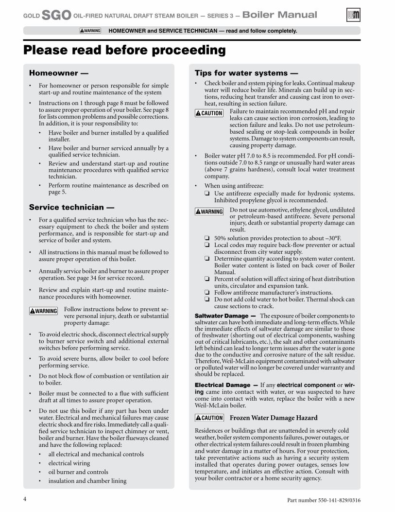
Tips for water systems —• Check boiler and system piping for leaks. Continual makeup
water will reduce boiler life. Minerals can build up in sec-tions, reducing heat transfer and causing cast iron to over-heat, resulting in section failure.
Failure to maintain recommended pH and repair leaks can cause section iron corrosion, leading to section failure and leaks. Do not use petroleum-based sealing or stop-leak compounds in boiler systems. Damage to system components can result, causing property damage.
• Boiler water pH 7.0 to 8.5 is recommended. For pH condi-tions outside 7.0 to 8.5 range or unusually hard water areas (above 7 grains hardness), consult local water treatment company.
• When using antifreeze: ❏ Use antifreeze especially made for hydronic systems.
Inhibited propylene glycol is recommended.
Do not use automotive, ethylene glycol, undiluted or petroleum-based antifreeze. Severe personal injury, death or substantial property damage can result.
❏ 50% solution provides protection to about –30°F. ❏ Local codes may require back-flow preventer or actual
disconnect from city water supply. ❏ Determine quantity according to system water content.
Boiler water content is listed on back cover of Boiler Manual.
❏ Percent of solution will affect sizing of heat distribution units, circulator and expansion tank.
❏ Follow antifreeze manufacturer’s instructions. ❏ Do not add cold water to hot boiler. Thermal shock can
cause sections to crack.
Saltwater Damage — The exposure of boiler components to saltwater can have both immediate and long-term effects. While the immediate effects of saltwater damage are similar to those of freshwater (shorting out of electrical components, washing out of critical lubricants, etc.), the salt and other contaminants left behind can lead to longer term issues after the water is gone due to the conductive and corrosive nature of the salt residue. Therefore, Weil-McLain equipment contaminated with saltwater or polluted water will no longer be covered under warranty and should be replaced.
Electrical Damage — If any electrical component or wir-ing came into contact with water, or was suspected to have come into contact with water, replace the boiler with a new Weil-McLain boiler.
Frozen Water Damage Hazard
Residences or buildings that are unattended in severely cold weather, boiler system components failures, power outages, or other electrical system failures could result in frozen plumbing and water damage in a matter of hours. For your protection, take preventative actions such as having a security system installed that operates during power outages, senses low temperature, and initiates an effective action. Consult with your boiler contractor or a home security agency.
Homeowner —• For homeowner or person responsible for simple
start-up and routine maintenance of the system
• Instructions on 1 through page 8 must be followed to assure proper operation of your boiler. See page 8 for lists common problems and possible corrections. In addition, it is your responsibility to:
• Have boiler and burner installed by a qualified installer.
• Have boiler and burner serviced annually by a qualified service technician.
• Review and understand start-up and routine maintenance procedures with qualified service technician.
• Perform routine maintenance as described on page 5.
Service technician —• For a qualified service technician who has the nec-
essary equipment to check the boiler and system performance, and is responsible for start-up and service of boiler and system.
• All instructions in this manual must be followed to assure proper operation of this boiler.
• Annually service boiler and burner to assure proper operation. See page 34 for service record.
• Review and explain start-up and routine mainte-nance procedures with homeowner.
Follow instructions below to prevent se-vere personal injury, death or substantial property damage:
• To avoid electric shock, disconnect electrical supply to burner service switch and additional external switches before performing service.
• To avoid severe burns, allow boiler to cool before performing service.
• Do not block flow of combustion or ventilation air to boiler.
• Boiler must be connected to a flue with sufficient draft at all times to assure proper operation.
• Do not use this boiler if any part has been under water. Electrical and mechanical failures may cause electric shock and fire risks. Immediately call a quali-fied service technician to inspect chimney or vent, boiler and burner. Have the boiler flueways cleaned and have the following replaced:
• all electrical and mechanical controls
• electrical wiring
• oil burner and controls
• insulation and chamber lining
Please read before proceeding

Part number 550-141-829/0316 5
GOLD SGO OIL-FIRED NATURAL DRAFT STEAM BOILER — SERIES 3 — Boiler Manual
HOMEOWNER and SERVICE TECHNICIAN — read and follow completely.
Routine maintenance schedule
Beginning each heating season
❏ Call a qualified service technician to perform annual service.
Daily during heating season
❏ Check that boiler area is free from combustible materials, gasoline and other flammable vapors and liquids.
Weekly during heating season
❏ Check for and remove any obstructions to flow of combustion or ventilation air to boiler.
❏ Check that breeching is attached between boiler and chimney. If breeching is loose or damaged, immediately turn off switch on boiler and call service technician to repair.
❏ Check for oil leaks in oil piping and around burner. If found, im-mediately call qualified service technician to correct situation.
❏ Check for water leaks in boiler and piping; also check for leaks around tankless heater plate, if installed. If found, immediately call service technician to repair.
❏ Check float-type low water cutoff, when used: Refer to control manufacturer’s instructions.
Scald potential. Do not blow down low water cutoff unless blow-down piping has been installed according to Boiler Manual. If piping is not in place, call qualified service technician to install.
Periodically during heating season
❏ Test probe-type low water cutoff, when used: refer to control manufacturer’s instructions.
End of heating season
❏ If tankless heater is installed, boiler will continue to operate. Check for the following:• All daily and weekly instructions listed on this page must be fol-
lowed.
• Burner motor may have to be oiled. Some motors are permanently lubricated and do not need additional oil. Check for oiling in-structions on burner or motor.
Boiler shutdown
❏ Do not drain boiler unless exposure to freezing temperatures will occur.
❏ Do not use antifreeze in steam systems. ❏ Always keep manual fuel supply shut off if burner is shut down for
an extended period of time.• Turn off switch at boiler and any external switch to boiler.• Close fuel valves. • Turn off water feed valve.• Cover burner to protect from dust and dampness.
Part number 550-141-829/03166
GOLD SGO OIL-FIRED NATURAL DRAFT STEAM BOILER — SERIES 3 — Boiler Manual
HOMEOWNER and SERVICE TECHNICIAN — read and follow completely.
OperationSGO with float-type low water cutoff
1. If burner does not fire, check for:
• Switch on boiler or additional shut-off switches turned off.
• Fuses or breaker switch tripped.
• Thermostat set below room temperature.
• Fuel valves turned off.
• Not enough oil in tank to supply burner.
• No water in gauge glass.
2. Correct problems found in step #1. If burner does not fire, press reset button on burner primary control only once. Repeated presses will deposit oil in combustion chamber.
Burner must never be fired when oil is in combus-tion chamber. Immediately call qualified service technician.
3. If burner still does not fire, call qualified service technician.
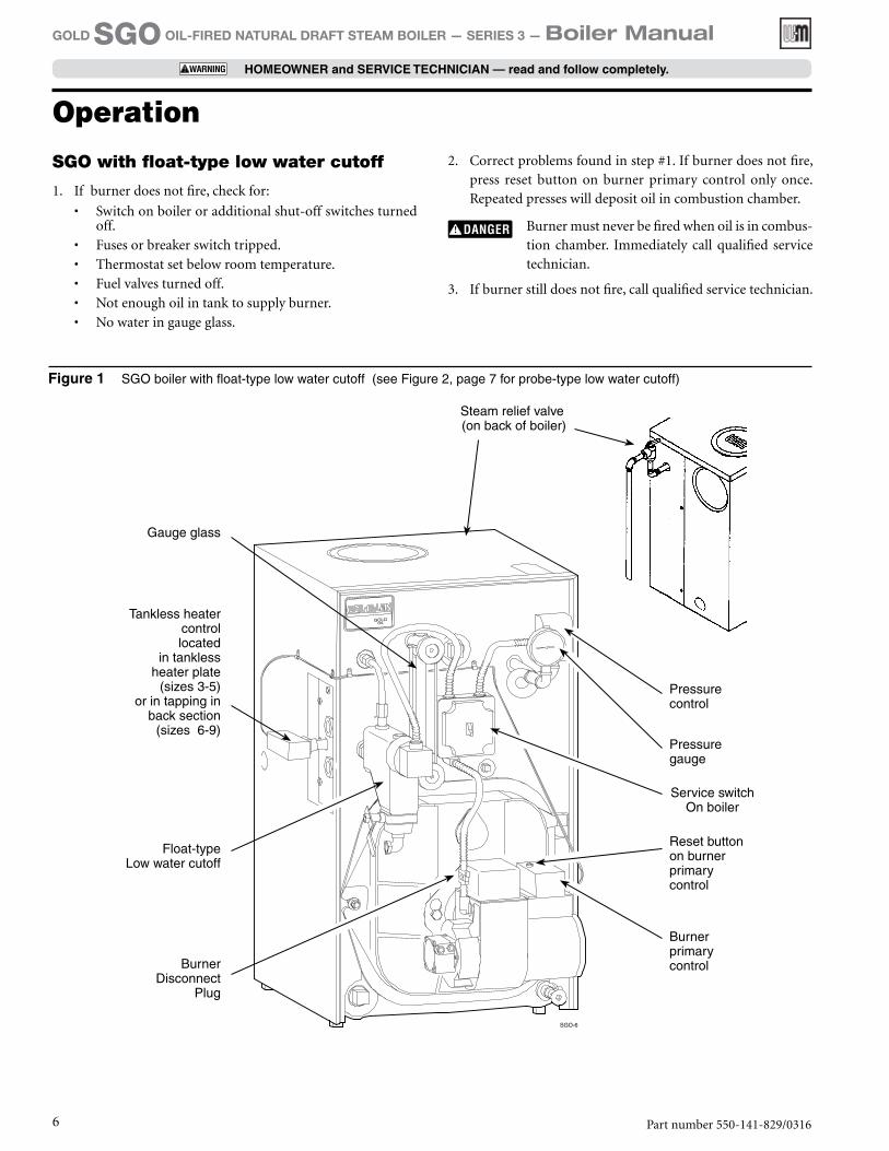
Figure 1 SGO boiler with float-type low water cutoff (see Figure 2, page 7 for probe-type low water cutoff)
Gauge glass
Steam relief valve (on back of boiler)
Tankless heater controllocated
in tankless heater plate
(sizes 3-5) or in tapping in
back section (sizes 6-9)
Float-type Low water cutoff
Pressure control
Pressure gauge
Burner primary control
Service switch On boiler
Reset button on burner primary control
Burner Disconnect
Plug

Part number 550-141-829/0316 7
GOLD SGO OIL-FIRED NATURAL DRAFT STEAM BOILER — SERIES 3 — Boiler Manual
HOMEOWNER and SERVICE TECHNICIAN — read and follow completely.
2. Correct problems found in step #1. If burner does not fire,
press reset button on burner primary control only once.
Repeated presses will deposit oil in combustion chamber.
Burner must never be fired when oil is in combus-
tion chamber. Immediately call qualified service
technician.
3. If burner still does not fire, call qualified service technician.
SGO with probe-type low water cutoff
1. If burner does not fire, check for:
• Service switch on boiler or additional switches turned off.
• Fuses or breaker switch tripped.
• Thermostat set below room temperature.
• Fuel valves turned off.
• Not enough oil in tank to supply burner.
• No water in gauge glass.
Figure 2 SGO boiler with probe-type low water cutoff (see Figure 1, page 6 for float-type low water cutoff)
Steam relief valve (on back of boiler)
Gauge glass
Probe-type low water cutoff
Reset button on burner primary control
Tankless heatercontrol
located in tankless heater plate
(sizes 3-5) or in tapping in
back section (sizes 6-9)
Pressure control
Pressure gauge
Burner primary controlBurner
Disconnect Plug
Service switch on boiler
Operation (continued)

Part number 550-141-829/03168
GOLD SGO OIL-FIRED NATURAL DRAFT STEAM BOILER — SERIES 3 — Boiler Manual
HOMEOWNER and SERVICE TECHNICIAN — read and follow completely.
Troubleshooting
Common problems Common causes Possible corrections
Rapid cycling - burner turns on and off frequently.
Thermostat installed where drafts or heat affect reading.
Locate thermostat on inner wall away from heat sources or cool drafts.
Heat anticipator in thermostat adjusted incorrectly.
Adjust heat anticipator to match current draw. Refer to boiler wiring diagram.
Incorrect limit setting. Have qualified service technician increase limit setting to decrease cycling. Normal operation is usually less than 5 psig.
Need to frequently add makeup water.
Leaks in boiler or piping. Have qualified service technician repair leaks at once to avoid constant use of makeup water.
Popping or percolating noise heard in boiler.
Mineral deposits in sections due to constant use of makeup water. Or incorrect pH.
Have qualified service technician de-lime boiler and repair leaks at once to avoid constant use of makeup water and check ph (7.0-8.5).
Metal flakes found in flueway. Contaminated combustion air supply. Remove sources of hydrocarbons in or near boiler area. (Bleaches, cleaners, chemicals, sprays, fabric softeners, paint remover, etc.)
Condensation of combustion gases. Have qualified service technician check boiler operation.
Isolated radiation does not heat. Air vents or traps inoperative. Have qualified service technician repair, clean or replace air vents or traps.
Water disappearing from gauge glass and back into system through return piping.
Incorrect Hartford loop piping. Have qualified service technician pipe boiler exactly as shown in boiler manual.
Check-valve inoperative. Have qualified service technician clean or replace check-valve.
Vacuum-breaker inoperative. Have qualified service technician clean or replace vacuum breaker.
Violent waterline fluctuations - surging.ORWater passing into steam mains - priming.
Dirt, oil or other impurities in water. Have qualified service technician skim boiler.
Waterline too high. Have qualified service technician adjust waterline to normal height.
Incorrect piping. Have qualified service technician pipe boiler exactly as shown in boiler manual.
Sudden release of boiler steam pressure by action of zone valves.
Have qualified service technician adjust valve operating time or install slow-opening valves.
Domestic water from tankless heater is hot then suddenly turns cold.OrDomestic water from tankless heater is always lukewarm.
Mineral deposits insulate internal waterways of heater.
Have qualified service technician delime or replace coil.
Boiler stop-leak compound has been added to boiler water and is insulating outside of coil.
Have qualified service technician remove and clean coil and drain and flush boiler to remove stop-leak.
Incorrect mixing valve setting for tankless heater.
Have qualified service technician adjust mixing valve setting.
Domestic flow rate too high. Have qualified service technician install flow check valve set to rating of tankless heater.
Incorrect setting on tankless heater control.
Have qualified service technician raise tankless control setting. Adjust differential on tankless control to lower setting.
Homeowners — The problems and corrections below represent common situations that can occur. There may be others not listed below. It is important always to contact a qualified service technician if you have any questions about the operation of your boiler or system.
Top View
Walls
Floor
Ceiling
Wall
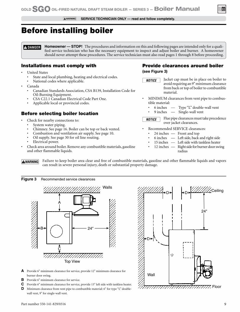
Figure 3 Recommended service clearances
24"
C
A
B
D D
D
24"
A Provide 6" minimum clearance for service, provide 12" minimum clearance for
burner door swing.
B Provide 6" minimum clearance for service.
C Provide 6" minimum clearance for service, provide 15" left side with tankless heater.
D Minimum clearance from vent pipe to combustible material: 6" for type “L” double-
wall vent, 9" for single-wall vent.
Part number 550-141-829/0316 9
GOLD SGO OIL-FIRED NATURAL DRAFT STEAM BOILER — SERIES 3 — Boiler Manual
SERVICE TECHNICIAN ONLY — read and follow completely.
Before installing boiler
Installations must comply with• United States
• State and local plumbing, heating and electrical codes.• National codes where applicable.
• Canada• Canadian Standards Association, CSA B139, Installation Code for
Oil-Burning Equipment.• CSA C22.1 Canadian Electrical Code Part One.• Applicable local or provincial codes.
Before selecting boiler location• Check for nearby connections to:
• System water piping.• Chimney. See page 16. Boiler can be top or back vented.• Combustion and ventilation air supply. See page 10.• Oil supply. See page 30 for oil line routing.• Electrical power.
• Check area around boiler. Remove any combustible materials, gasoline and other flammable liquids.
Provide clearances around boiler (see Figure 3)
Jacket cap must be in place on boiler to avoid requiring an 9" minimum clearance from back or top of boiler to combustible material.
• MINIMUM clearances from vent pipe to combus-tible material:• 6 inches — Type “L” double-wall vent• 9 inches — Single-wall vent
Flue pipe clearances must take precedence over jacket clearances.
• Recommended SERVICE clearances:• 24 inches — Front and top• 6 inches — Left side, back and right side• 15 inches — Left side with tankless heater • 12 inches — Right side for burner door swing
radius
Failure to keep boiler area clear and free of combustible materials, gasoline and other flammable liquids and vapors can result in severe personal injury, death or substantial property damage.
Homeowner — STOP! The procedures and information on this and following pages are intended only for a quali-fied service technician who has the necessary equipment to inspect and adjust boiler and burner. A homeowner should never attempt these procedures. The service technician must also read pages 1 through 8 before proceeding.
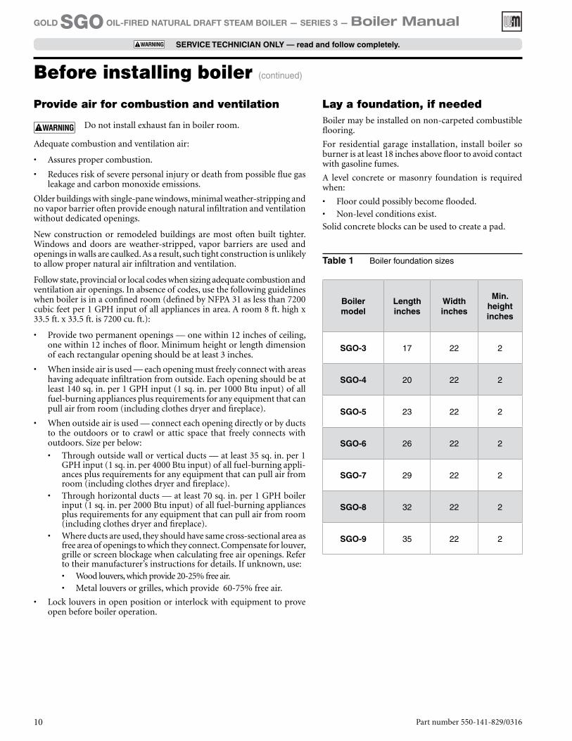
Table 1 Boiler foundation sizes
Part number 550-141-829/031610
GOLD SGO OIL-FIRED NATURAL DRAFT STEAM BOILER — SERIES 3 — Boiler Manual
SERVICE TECHNICIAN ONLY — read and follow completely.
Provide air for combustion and ventilation
Do not install exhaust fan in boiler room.
Adequate combustion and ventilation air:
• Assures proper combustion.
• Reduces risk of severe personal injury or death from possible flue gas leakage and carbon monoxide emissions.
Older buildings with single-pane windows, minimal weather-stripping and no vapor barrier often provide enough natural infiltration and ventilation without dedicated openings.
New construction or remodeled buildings are most often built tighter. Windows and doors are weather-stripped, vapor barriers are used and openings in walls are caulked. As a result, such tight construction is unlikely to allow proper natural air infiltration and ventilation.
Follow state, provincial or local codes when sizing adequate combustion and ventilation air openings. In absence of codes, use the following guidelines when boiler is in a confined room (defined by NFPA 31 as less than 7200 cubic feet per 1 GPH input of all appliances in area. A room 8 ft. high x 33.5 ft. x 33.5 ft. is 7200 cu. ft.):
• Provide two permanent openings — one within 12 inches of ceiling, one within 12 inches of floor. Minimum height or length dimension of each rectangular opening should be at least 3 inches.
• When inside air is used — each opening must freely connect with areas having adequate infiltration from outside. Each opening should be at least 140 sq. in. per 1 GPH input (1 sq. in. per 1000 Btu input) of all fuel-burning appliances plus requirements for any equipment that can pull air from room (including clothes dryer and fireplace).
• When outside air is used — connect each opening directly or by ducts to the outdoors or to crawl or attic space that freely connects with outdoors. Size per below:
• Through outside wall or vertical ducts — at least 35 sq. in. per 1 GPH input (1 sq. in. per 4000 Btu input) of all fuel-burning appli-ances plus requirements for any equipment that can pull air from room (including clothes dryer and fireplace).
• Through horizontal ducts — at least 70 sq. in. per 1 GPH boiler input (1 sq. in. per 2000 Btu input) of all fuel-burning appliances plus requirements for any equipment that can pull air from room (including clothes dryer and fireplace).
• Where ducts are used, they should have same cross-sectional area as free area of openings to which they connect. Compensate for louver, grille or screen blockage when calculating free air openings. Refer to their manufacturer’s instructions for details. If unknown, use:• Wood louvers, which provide 20-25% free air.• Metal louvers or grilles, which provide 60-75% free air.
• Lock louvers in open position or interlock with equipment to prove open before boiler operation.
Lay a foundation, if neededBoiler may be installed on non-carpeted combustible flooring.
For residential garage installation, install boiler so burner is at least 18 inches above floor to avoid contact with gasoline fumes.
A level concrete or masonry foundation is required when:
• Floor could possibly become flooded.
• Non-level conditions exist.
Solid concrete blocks can be used to create a pad.
Boiler model
Length inches
Width inches
Min. height inches
SGO-3 17 22 2
SGO-4 20 22 2
SGO-5 23 22 2
SGO-6 26 22 2
SGO-7 29 22 2
SGO-8 32 22 2
SGO-9 35 22 2
Before installing boiler (continued)
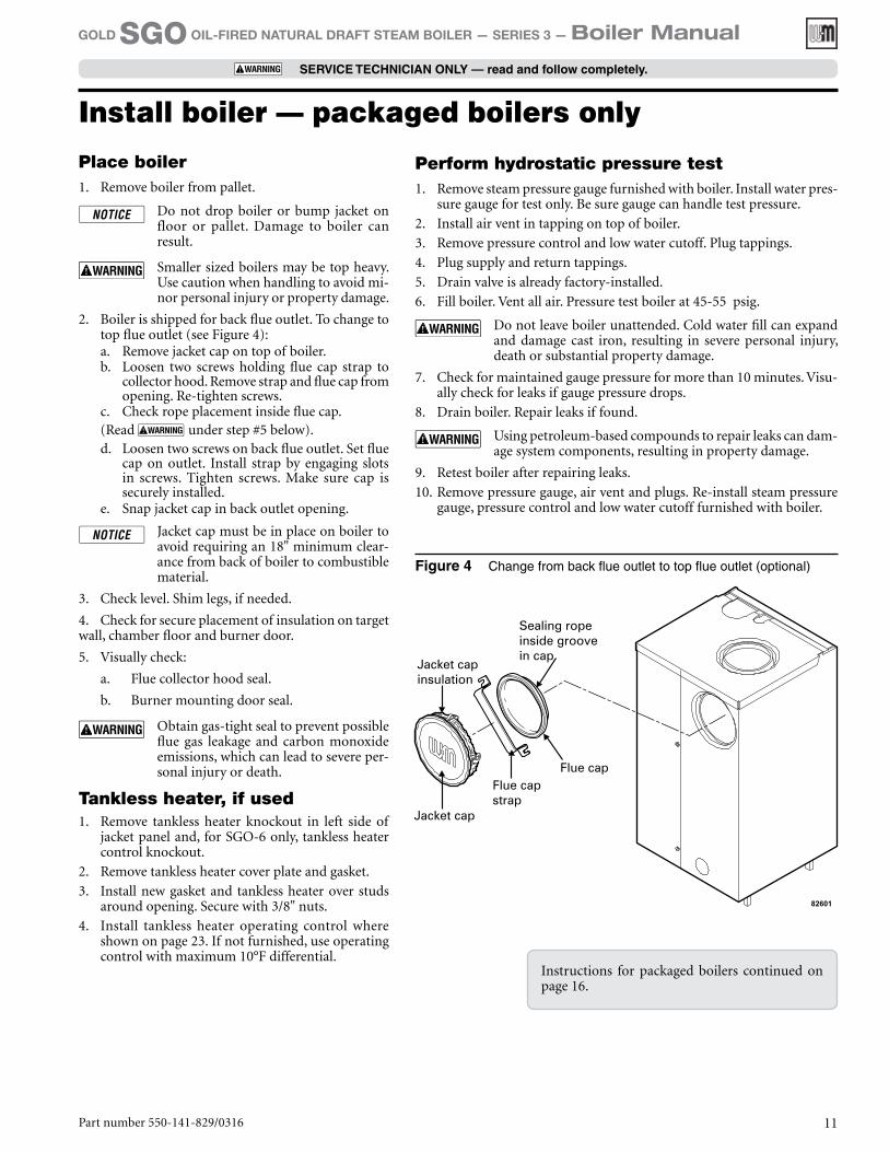
Figure 4 Change from back flue outlet to top flue outlet (optional)
Instructions for packaged boilers continued on page 16.
Install boiler — packaged boilers only
Part number 550-141-829/0316 11
GOLD SGO OIL-FIRED NATURAL DRAFT STEAM BOILER — SERIES 3 — Boiler Manual
SERVICE TECHNICIAN ONLY — read and follow completely.
Place boiler1. Remove boiler from pallet.
Do not drop boiler or bump jacket on floor or pallet. Damage to boiler can result.
Smaller sized boilers may be top heavy. Use caution when handling to avoid mi-nor personal injury or property damage.
2. Boiler is shipped for back flue outlet. To change to top flue outlet (see Figure 4):a. Remove jacket cap on top of boiler.b. Loosen two screws holding flue cap strap to
collector hood. Remove strap and flue cap from opening. Re-tighten screws.
c. Check rope placement inside flue cap. (Read under step #5 below).
d. Loosen two screws on back flue outlet. Set flue cap on outlet. Install strap by engaging slots in screws. Tighten screws. Make sure cap is securely installed.
e. Snap jacket cap in back outlet opening.
Jacket cap must be in place on boiler to avoid requiring an 18" minimum clear-ance from back of boiler to combustible material.
3. Check level. Shim legs, if needed.
4. Check for secure placement of insulation on target wall, chamber floor and burner door.
5. Visually check:
a. Flue collector hood seal.
b. Burner mounting door seal.
Obtain gas-tight seal to prevent possible flue gas leakage and carbon monoxide emissions, which can lead to severe per-sonal injury or death.
Tankless heater, if used1. Remove tankless heater knockout in left side of
jacket panel and, for SGO-6 only, tankless heater control knockout.
2. Remove tankless heater cover plate and gasket.
3. Install new gasket and tankless heater over studs around opening. Secure with 3/8" nuts.
4. Install tankless heater operating control where shown on page 23. If not furnished, use operating control with maximum 10°F differential.
Perform hydrostatic pressure test1. Remove steam pressure gauge furnished with boiler. Install water pres-
sure gauge for test only. Be sure gauge can handle test pressure.
2. Install air vent in tapping on top of boiler.
3. Remove pressure control and low water cutoff. Plug tappings.
4. Plug supply and return tappings.
5. Drain valve is already factory-installed.
6. Fill boiler. Vent all air. Pressure test boiler at 45-55 psig.
Do not leave boiler unattended. Cold water fill can expand and damage cast iron, resulting in severe personal injury, death or substantial property damage.
7. Check for maintained gauge pressure for more than 10 minutes. Visu-ally check for leaks if gauge pressure drops.
8. Drain boiler. Repair leaks if found.
Using petroleum-based compounds to repair leaks can dam-age system components, resulting in property damage.
9. Retest boiler after repairing leaks.
10. Remove pressure gauge, air vent and plugs. Re-install steam pressure gauge, pressure control and low water cutoff furnished with boiler.
Part number 550-141-829/031612
GOLD SGO OIL-FIRED NATURAL DRAFT STEAM BOILER — SERIES 3 — Boiler Manual
SERVICE TECHNICIAN ONLY — read and follow completely.
Fiberglass wool and ceramic fiber materials are possible cancer hazards. See warning on page 37.
Place boiler1. Non-Packaged SGO-3 through 6 — position on site.
Smaller sized boilers may be top heavy. Use caution when handling to avoid minor personal injury or property damage.
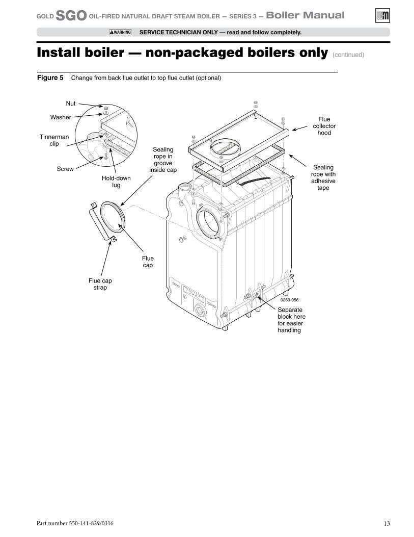
a. Boiler is shipped for back flue outlet. To change to top flue outlet (see Figure 5, page 13):• Loosen two screws holding flue cap strap
to collector hood. Remove strap and flue cap from opening. Re-tighten screws.
• Ch e ck rop e p l a ce m e n t i n s i d e f lu e c a p. (Read under step #3 at right).
• Loosen two screws on back flue outlet. Set flue cap on outlet. Install strap by engaging slots in screws. Tighten screws. Make sure cap is securely installed.
2. Non-Packaged SGO-7, 8 & 9 — split the assembled block for easier handling (see Figure 5):a. Open burner mounting door and using utility knife, slit
floor insulation at joint to be separated.b. Remove 5½" draw rod and the longest draw rod from
each side. Pull block apart. Save draw rods, nuts, washers and sealing rings for reassembly.
c. Move divided block to location.d. Clean port openings with clean rag.
Do not use petroleum-based compounds to clean openings. Damage to system components can result causing property damage.
e. Place rings in port openings. If ring slips out of groove, stretch ring gently for several seconds, then place in groove.
f. Position sections so aligning lugs fit into sockets of next section. Make sure sealing rope is in good condition and in position.
g. Oil threads on draw rods. Install washer and nut on end to be tightened. Use nut only on other end.
h. With w rench at washer/nut end, uni formly tighten nuts starting with 5½" rod at large port, 5½" rod at small port, bottom long rod and finally top long rod.
a. Torque on both 5½" rods and bottom long rod should be 50-60 ft. lbs; long top rod should be 20-25 ft. lbs. Do not back-off nuts.
b. Metal-to-metal contact should be made around port openings. If gap does exist, it should be less than .020". Check with feeler gauge.
c. If gap around port openings exceeds .020", check for dirt on port openings, sockets or misaligned lugs. If corrections are made and gap still exists, contact your Weil-McLain distributor or sales office before continu-ing installation.
3. Non-Packaged SGO-7, 8 & 9 — install flue collector hood (see Figure 5):
Obtain gas-tight seal to prevent possible flue gas leakage and carbon monoxide emissions, leading to severe personal injury or death.
a. Thread Tinnerman clip on screw so that clip fits snugly in notch of hold-down lug. Screw must not turn.
b. Remove paper on sealing rope. Starting at back section near flue collar, position sealing rope around top of block with adhesive side to sections. Do not stretch rope. Make sure rope ends meet. Trim excess rope.
c. Position flue collector hood on top of boiler sections and over screws and clips as shown in Figure 5.
d. Install washers and nuts. Tighten nuts until collector hood makes contact with Tinnerman clip.
e. Position flue cap• Back flue outlet boiler — Position flue cap and strap
over opening in flue collector hood. Make sure rope in cap is in place and in good condition. Tighten strap to hood with screws provided.
• Top flue outlet boiler — Position flue cap and strap over opening in back section. Make sure rope in cap is in place and in good condition. Tighten strap to boiler with screws provided in section. Install remain-ing screws in holes in flue collector hood.
4. Check level. Shim legs, if needed.
Tankless heater, if used1. SGO-3 through 6 — remove knockout in left side jacket
panel, and for SGO-6 only, remove tankless heater control knockout.
2. Remove tankless heater cover plate and gasket.
3. Install new gasket and tankless heater over studs around opening. Secure with 3/8" nuts.
Install boiler — non-packaged boilers only
Part number 550-141-829/0316 13
GOLD SGO OIL-FIRED NATURAL DRAFT STEAM BOILER — SERIES 3 — Boiler Manual
SERVICE TECHNICIAN ONLY — read and follow completely.
Figure 5 Change from back flue outlet to top flue outlet (optional)
Install boiler — non-packaged boilers only (continued)
Sealing rope in groove
inside cap
Flue cap
Flue cap strap
Flue collector
hood
Sealing rope with adhesive
tape
Nut
Washer
Tinnerman clip
Screw
Hold-down lug
Separate block here for easier handling
Install boiler — non-packaged boilers only (continued)
Part number 550-141-829/031614
GOLD SGO OIL-FIRED NATURAL DRAFT STEAM BOILER — SERIES 3 — Boiler Manual
SERVICE TECHNICIAN ONLY — read and follow completely.
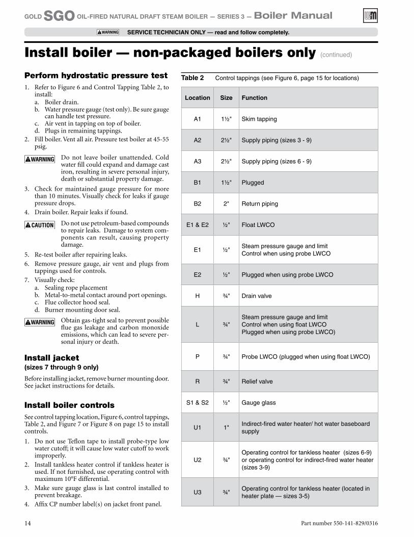
Location Size Function
A1 1½" Skim tapping
A2 2½" Supply piping (sizes 3 - 9)
A3 2½" Supply piping (sizes 6 - 9)
B1 1½" Plugged
B2 2" Return piping
E1 & E2 ½" Float LWCO
E1 ½"Steam pressure gauge and limitControl when using probe LWCO
E2 ½" Plugged when using probe LWCO
H ¾" Drain valve
L ¾"Steam pressure gauge and limitControl when using float LWCOPlugged when using probe LWCO)
P ¾" Probe LWCO (plugged when using float LWCO)
R ¾" Relief valve
S1 & S2 ½" Gauge glass
U1 1"Indirect-fired water heater/ hot water baseboard supply
U2 ¾"Operating control for tankless heater (sizes 6-9) or operating control for indirect-fired water heater (sizes 3-9)
U3 ¾"Operating control for tankless heater (located in heater plate — sizes 3-5)
Perform hydrostatic pressure test1. Refer to Figure 6 and Control Tapping Table 2, to
install:a. Boiler drain.b. Water pressure gauge (test only). Be sure gauge
can handle test pressure.c. Air vent in tapping on top of boiler.d. Plugs in remaining tappings.
2. Fill boiler. Vent all air. Pressure test boiler at 45-55 psig.
Do not leave boiler unattended. Cold water fill could expand and damage cast iron, resulting in severe personal injury, death or substantial property damage.
3. Check for maintained gauge pressure for more than 10 minutes. Visually check for leaks if gauge pressure drops.
4. Drain boiler. Repair leaks if found.
Do not use petroleum-based compounds to repair leaks. Damage to system com-ponents can result, causing property damage.
5. Re-test boiler after repairing leaks.
6. Remove pressure gauge, air vent and plugs from tappings used for controls.
7. Visually check:a. Sealing rope placementb. Metal-to-metal contact around port openings.c. Flue collector hood seal.d. Burner mounting door seal.
Obtain gas-tight seal to prevent possible flue gas leakage and carbon monoxide emissions, which can lead to severe per-sonal injury or death.
Table 2 Control tappings (see Figure 6, page 15 for locations)
Install jacket (sizes 7 through 9 only)
Before installing jacket, remove burner mounting door. See jacket instructions for details.
Install boiler controlsSee control tapping location, Figure 6, control tappings, Table 2, and Figure 7 or Figure 8 on page 15 to install controls.
1. Do not use Teflon tape to install probe-type low water cutoff; it will cause low water cutoff to work improperly.
2. Install tankless heater control if tankless heater is used. If not furnished, use operating control with maximum 10°F differential.
3. Make sure gauge glass is last control installed to prevent breakage.
4. Affix CP number label(s) on jacket front panel.
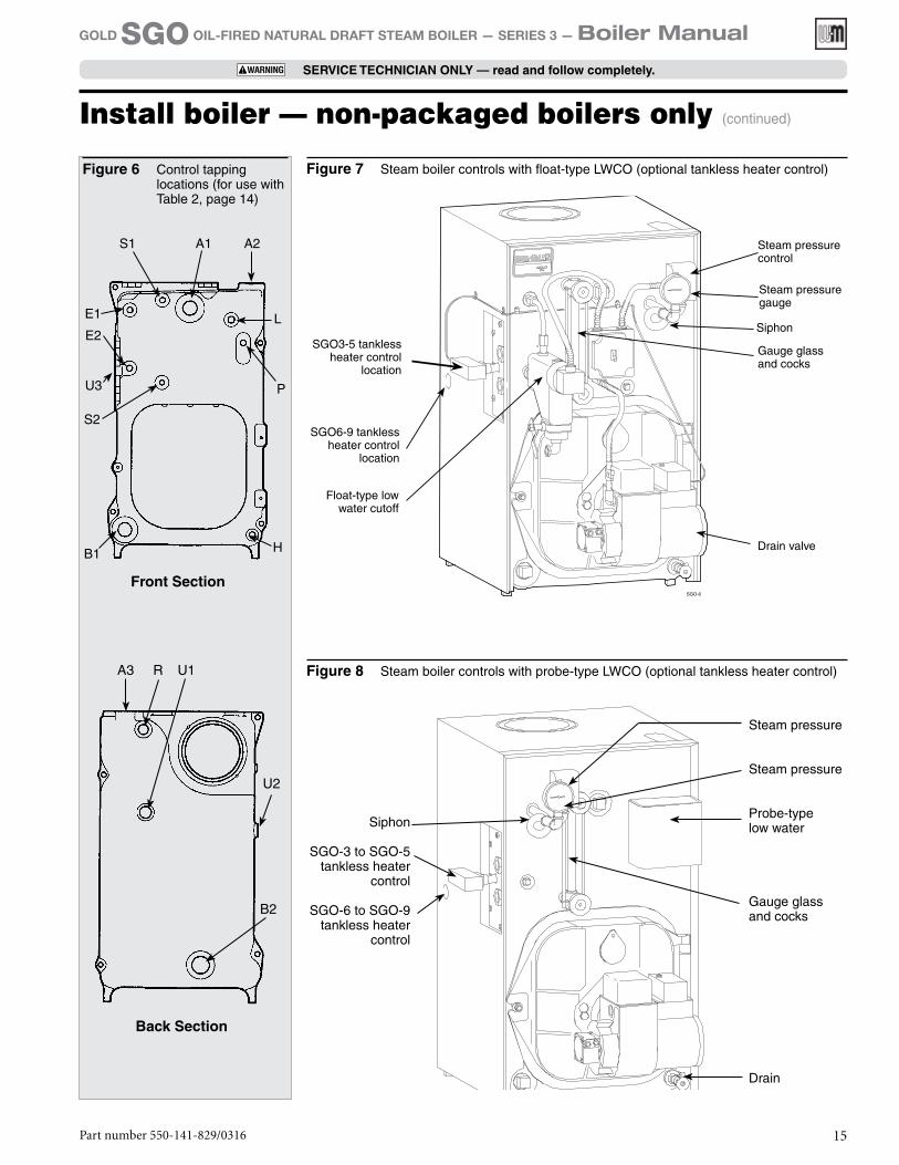
Figure 6 Control tapping locations (for use with Table 2, page 14)
U3
Front Section
A1 A2S1
L
P
HB1
S2
E2
E1
Back Section
R U1
U2
A3
B2
SGO3-5 tankless heater control
location
SGO6-9 tankless heater control
location
Float-type low water cutoff
Steam pressure control
Steam pressure gauge
Gauge glass and cocks
Drain valve
Siphon
Figure 7 Steam boiler controls with float-type LWCO (optional tankless heater control)
Figure 8 Steam boiler controls with probe-type LWCO (optional tankless heater control)
Siphon
SGO-3 to SGO-5tankless heater
control
SGO-6 to SGO-9tankless heater
control
Steam pressure
Steam pressure
Probe-typelow water
Gauge glass and cocks
Drain
Install boiler — non-packaged boilers only (continued)
Part number 550-141-829/0316 15
GOLD SGO OIL-FIRED NATURAL DRAFT STEAM BOILER — SERIES 3 — Boiler Manual
SERVICE TECHNICIAN ONLY — read and follow completely.
Part number 550-141-829/031616
GOLD SGO OIL-FIRED NATURAL DRAFT STEAM BOILER — SERIES 3 — Boiler Manual
SERVICE TECHNICIAN ONLY — read and follow completely.
Install burner (also refer to instructions packed with burner)
Use only burners specified for use on Weil-McLain GOLD oil boilers. DO NOT use burners specified for use on Weil-McLain Model 68 boilers. Contact individual burner manufacturers for proper burner selections.
For P-SGO and A-SGO boiler:1. Secure universal mounting flange and gasket to
burner mounting door. Use three bolts provided.
2. Secure burner on flange with three bolts.
3. Position burner so end of air tube is level to 1½-de-gree tilt down toward chamber. Open door to verify burner position. End of air tube should be flush to ¼" recessed from inside wall of burner door refrac-tory. Check for secure placement of insulation on target wall, chamber floor and burner mounting door. Securely close door.
General chimney requirements• Designed for natural draft firing. Connect boiler
to vertical chimney.
Insufficient draft can cause flue gas leak-age and carbon monoxide emissions, which will lead to severe personal injury or death.
• Use vent material approved by local codes for oil-fired burners. In their absence, refer to:• NFPA 31, Installation of Oil-Burning Equip-
ment.• NFPA 211, Standard for Chimneys, Fireplaces,
Vents and Solid Fuel Burning Appliances.• In Canada, refer to CSA B139, Installation Code
for Oil-Burning Equipment.• NFPA 211 requires chimney to be lined before con-
nected to boiler.
Inspect existing chimney before installing new boiler. Failure to do any of the following will result in severe personal injury or death:
• Clean chimney, including removal of blockage.• Repair or replace damaged pipe or liner.• Repair mortar and joints.
To prevent downdrafts, extend chimney at least 3 feet above highest point where it passes through roof and 2 feet higher than any portion of building within 10 feet. Increase chimney cross-sectional area and height at least 4% per 1,000 feet above sea level.
• Minimum clearances from vent pipe to combustible material:• 6 inches — Type “L” double-wall vent• 9 inches — Single-wall vent
• Minimum chimney sizes should be used.
Oversized chimneys, outside masonry chimneys and/or derated inputs can result in condensation in chimney.
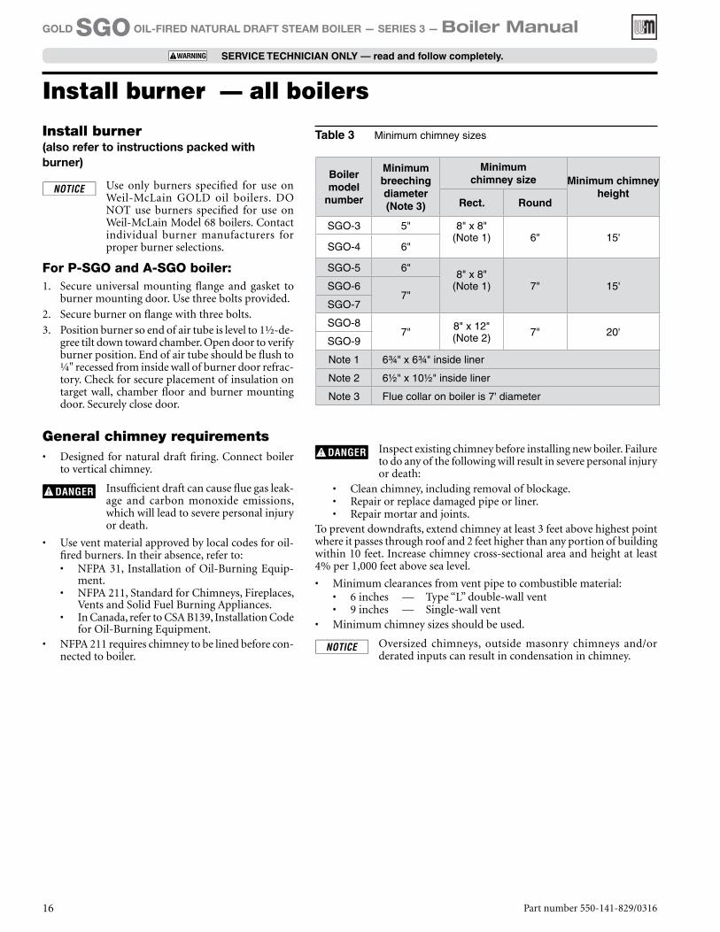
Boiler model
number
Minimum breeching diameter(Note 3)
Minimum chimney size Minimum chimney
heightRect. Round
SGO-3 5" 8" x 8" (Note 1) 6" 15'
SGO-4 6"
SGO-5 6"8" x 8"
(Note 1) 7" 15'SGO-67"
SGO-7
SGO-87" 8" x 12"
(Note 2) 7" 20'SGO-9
Note 1 6¾" x 6¾" inside liner
Note 2 6½" x 10½" inside liner
Note 3 Flue collar on boiler is 7' diameter
Table 3 Minimum chimney sizes
Install burner — all boilers

Part number 550-141-829/0316 17
GOLD SGO OIL-FIRED NATURAL DRAFT STEAM BOILER — SERIES 3 — Boiler Manual
SERVICE TECHNICIAN ONLY — read and follow completely.
Connect breechingConnect breeching
Long horizontal breechings, excessive number of tees and elbows, or other obstructions restricting combustion gas flow can result in possibility of con-densation, flue gas leakage and carbon monoxide emissions, which can lead to severe personal injury or death.
1. Install two (2) flue pipe brackets.
2. Connect full-sized breeching when possible. See Minimum Chimney Size Table.• Back outlet — see Figure 9.• Top outlet — see Figure 10.
3. Connection must be made above bottom of chimney to avoid blockage. Breeching must not enter chimney far enough to cause obstruction. Use thimble or slip joint where breeching enters chimney to allow removal for cleaning.
4. When burner and boiler are properly installed, draft overfire will be approximately -0.01" to -0.02" W.C. Install barometric control in breeching, per control manufacturer’s instructions, when excess draft needs to be relieved or to comply with applicable codes and regulations. Use draft gauge to adjust proper opening.
5. An induced draft fan for the chimney may be necessary if:• Excessive resistance to flow of combustion gases
can be expected.• Cross-sectional area of chimney is smaller than
minimum recommended.• Chimney height is less than recommended.
Seal all vent joints. Interlock burner with fan operation.
Figure 9 Back outlet breeching connection
Figure 10 Top outlet breeching connection
Typical location for barometric control(Also see control manufacturer’s
instructions)
Flue pipe bracket
(One on each side of pipe)
Typical location for barometric control(Also see control manufacturer’s instructions)
Flue pipe bracket(One on each side of pipe)
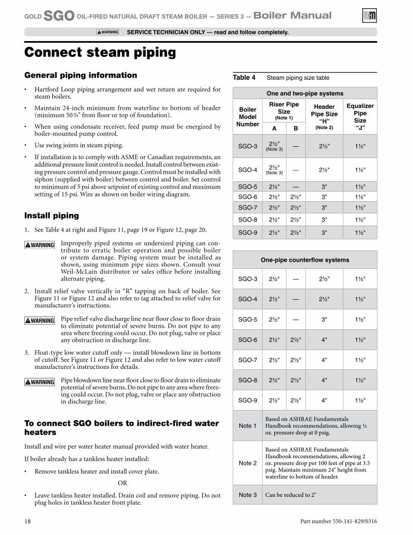
General piping information
• Hartford Loop piping arrangement and wet return are required for steam boilers.
• Maintain 24-inch minimum from waterline to bottom of header (minimum 507/8" from floor or top of foundation).
• When using condensate receiver, feed pump must be energized by boiler-mounted pump control.
• Use swing joints in steam piping.
• If installation is to comply with ASME or Canadian requirements, an additional pressure limit control is needed. Install control between exist-ing pressure control and pressure gauge. Control must be installed with siphon (supplied with boiler) between control and boiler. Set control to minimum of 5 psi above setpoint of existing control and maximum setting of 15 psi. Wire as shown on boiler wiring diagram.
Install piping
1. See Table 4 at right and Figure 11, page 19 or Figure 12, page 20.
Improperly piped systems or undersized piping can con-tribute to erratic boiler operation and possible boiler or system damage. Piping system must be installed as shown, using minimum pipe sizes shown. Consult your Weil-McLain distributor or sales office before installing alternate piping.
2. Install relief valve vertically in “R” tapping on back of boiler. See Figure 11 or Figure 12 and also refer to tag attached to relief valve for manufacturer’s instructions.
Pipe relief valve discharge line near floor close to floor drain to eliminate potential of severe burns. Do not pipe to any area where freezing could occur. Do not plug, valve or place any obstruction in discharge line.
3. Float-type low water cutoff only — install blowdown line in bottom of cutoff. See Figure 11 or Figure 12 and also refer to low water cutoff manufacturer’s instructions for details.
Pipe blowdown line near floor close to floor drain to eliminate potential of severe burns. Do not pipe to any area where freez-ing could occur. Do not plug, valve or place any obstruction in discharge line.
To connect SGO boilers to indirect-fired water heaters
Install and wire per water heater manual provided with water heater.
If boiler already has a tankless heater installed:
• Remove tankless heater and install cover plate.
OR
• Leave tankless heater installed. Drain coil and remove piping. Do not plug holes in tankless heater front plate.
Connect steam piping
Table 4 Steam piping size table
One and two-pipe systems
Boiler Model
Number
Riser Pipe Size
(Note 1)
Header Pipe Size
“H” (Note 2)
Equalizer Pipe Size “J”A B
SGO-3 2½" (Note 3) — 2½” 1½"
SGO-4 2½" (Note 3) — 2½" 1½"
SGO-5 2½" — 3" 1½"
SGO-6 2½" 2½" 3" 1½"
SGO-7 2½" 2½" 3" 1½"
SGO-8 2½" 2½" 3" 1½"
SGO-9 2½" 2½" 3" 1½"
One-pipe counterflow systems
SGO-3 2½" — 2½” 1½"
SGO-4 2½" — 2½" 1½"
SGO-5 2½" — 3" 1½"
SGO-6 2½" 2½" 4" 1½"
SGO-7 2½" 2½" 4" 1½"
SGO-8 2½" 2½" 4" 1½"
SGO-9 2½" 2½" 4" 1½"
Note 1Based on ASHRAE Fundamentals Handbook recommendations, allowing ½ oz. pressure drop at 0 psig.
Note 2
Based on ASHRAE Fundamentals Handbook recommendations, allowing 2 oz. pressure drop per 100 feet of pipe at 3.5 psig. Maintain minimum 24" height from waterline to bottom of header.
Note 3 Can be reduced to 2"
Part number 550-141-829/031618
GOLD SGO OIL-FIRED NATURAL DRAFT STEAM BOILER — SERIES 3 — Boiler Manual
SERVICE TECHNICIAN ONLY — read and follow completely.
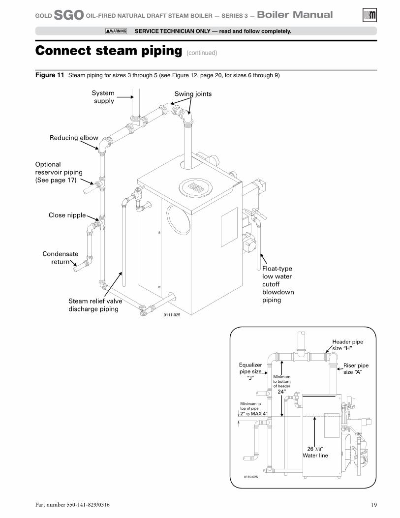
Connect steam piping (continued)
Figure 11 Steam piping for sizes 3 through 5 (see Figure 12, page 20, for sizes 6 through 9)
Part number 550-141-829/0316 19
GOLD SGO OIL-FIRED NATURAL DRAFT STEAM BOILER — SERIES 3 — Boiler Manual
SERVICE TECHNICIAN ONLY — read and follow completely.
Part number 550-141-829/031620
GOLD SGO OIL-FIRED NATURAL DRAFT STEAM BOILER — SERIES 3 — Boiler Manual
SERVICE TECHNICIAN ONLY — read and follow completely.
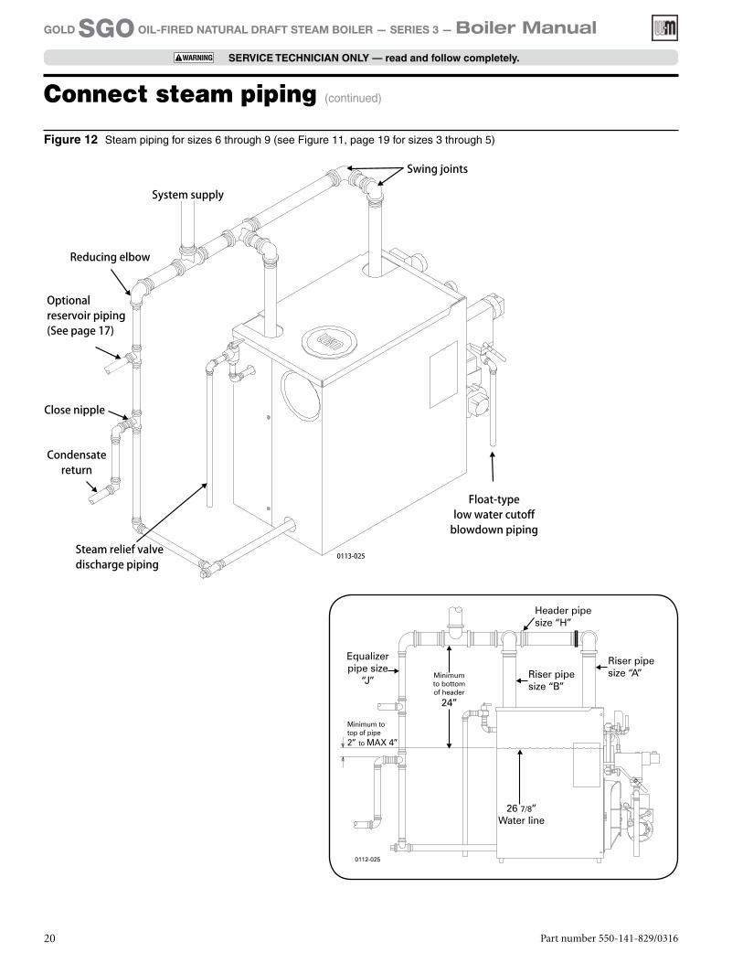
Figure 12 Steam piping for sizes 6 through 9 (see Figure 11, page 19 for sizes 3 through 5)
Connect steam piping (continued)
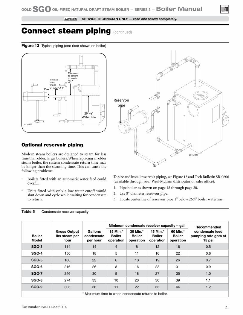
Figure 13 Typical piping (one riser shown on boiler)
Part number 550-141-829/0316 21
GOLD SGO OIL-FIRED NATURAL DRAFT STEAM BOILER — SERIES 3 — Boiler Manual
SERVICE TECHNICIAN ONLY — read and follow completely.
Table 5 Condensate receiver capacity
BoilerModel
Gross Output lbs steam per
hour
Gallons condensate
per hour
Minimum condensate receiver capacity – gal. Recommended condensate feed
pumping rate gpm at 15 psi
15 Min.* Boiler
operation
30 Min.* Boiler
operation
45 Min.* Boiler
operation
60 Min.* Boiler
operation
SGO-3 114 14 4 8 12 16 0.5
SGO-4 150 18 5 11 16 22 0.6
SGO-5 180 22 6 13 19 26 0.7
SGO-6 216 26 8 16 23 31 0.9
SGO-7 246 30 9 18 27 35 1.0
SGO-8 274 33 10 20 30 39 1.1
SGO-9 303 36 11 22 33 44 1.2
* Maximum time to when condensate returns to boiler.
Optional reservoir piping
Modern steam boilers are designed to steam for less time than older, larger boilers. When replacing an older steam boiler, the system condensate return time may be longer than the steaming time. This can cause the following problems:
• Boilers fitted with an automatic water feed could overfill.
• Units fitted with only a low water cutoff would shut down and cycle while waiting for condensate to return.
To size and install reservoir piping, see Figure 13 and Tech Bulletin SB-0606 (available through your Weil-McLain distributor or sales office):
1. Pipe boiler as shown on page 18 through page 20.
2. Use 8" diameter reservoir pipe.
3. Locate centerline of reservoir pipe 1" below 267/8" boiler waterline.
Connect steam piping (continued)
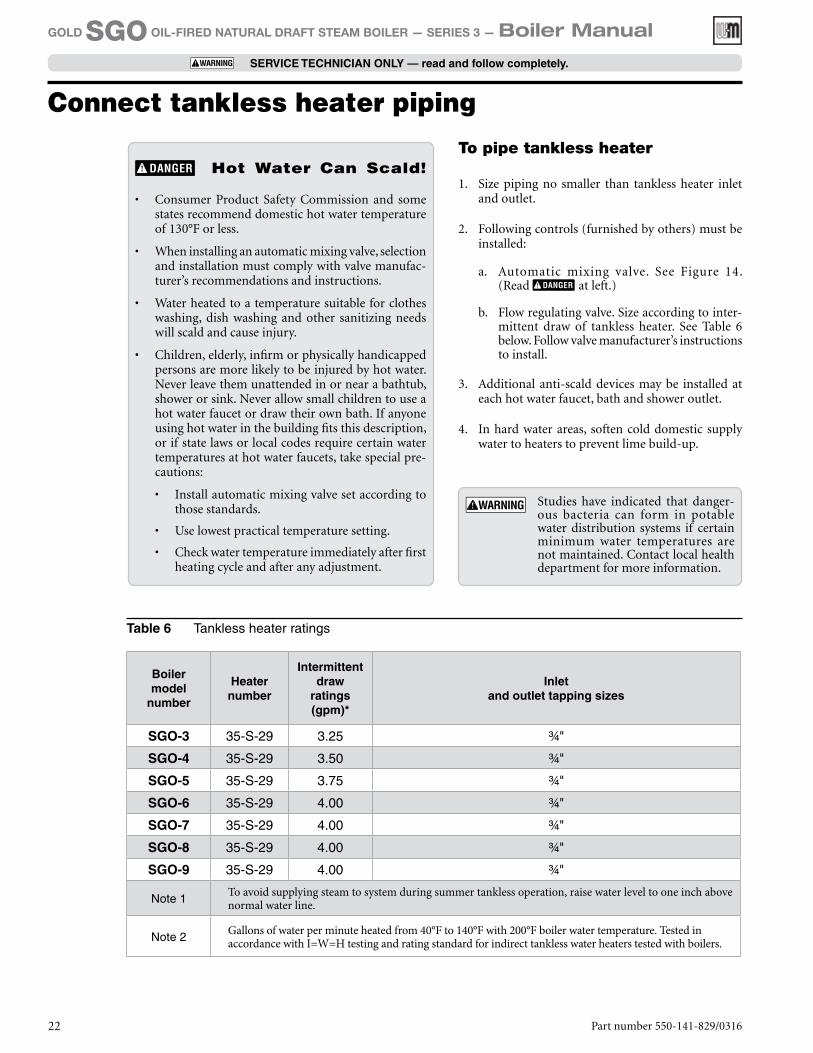
Table 6 Tankless heater ratings
Boiler model
number
Heater number
Intermittent draw
ratings (gpm)*
Inlet and outlet tapping sizes
SGO-3 35-S-29 3.25 ¾"
SGO-4 35-S-29 3.50 ¾"
SGO-5 35-S-29 3.75 ¾"
SGO-6 35-S-29 4.00 ¾"
SGO-7 35-S-29 4.00 ¾"
SGO-8 35-S-29 4.00 ¾"
SGO-9 35-S-29 4.00 ¾"
Note 1To avoid supplying steam to system during summer tankless operation, raise water level to one inch above normal water line.
Note 2Gallons of water per minute heated from 40°F to 140°F with 200°F boiler water temperature. Tested in accordance with I=W=H testing and rating standard for indirect tankless water heaters tested with boilers.
To pipe tankless heater
1. Size piping no smaller than tankless heater inlet and outlet.
2. Following controls (furnished by others) must be installed:
a. Automatic mixing valve. See Figure 14. (Read at left.)
b. Flow regulating valve. Size according to inter-mittent draw of tankless heater. See Table 6 below. Follow valve manufacturer’s instructions to install.
3. Additional anti-scald devices may be installed at each hot water faucet, bath and shower outlet.
4. In hard water areas, soften cold domestic supply water to heaters to prevent lime build-up.
Connect tankless heater piping
Hot Water Can Scald!
• Consumer Product Safety Commission and some states recommend domestic hot water temperature of 130°F or less.
• When installing an automatic mixing valve, selection and installation must comply with valve manufac-turer’s recommendations and instructions.
• Water heated to a temperature suitable for clothes washing, dish washing and other sanitizing needs will scald and cause injury.
• Children, elderly, infirm or physically handicapped persons are more likely to be injured by hot water. Never leave them unattended in or near a bathtub, shower or sink. Never allow small children to use a hot water faucet or draw their own bath. If anyone using hot water in the building fits this description, or if state laws or local codes require certain water temperatures at hot water faucets, take special pre-cautions:
• Install automatic mixing valve set according to those standards.
• Use lowest practical temperature setting.
• Check water temperature immediately after first heating cycle and after any adjustment.
Studies have indicated that danger-ous bacteria can form in potable water distribution systems if certain minimum water temperatures are not maintained. Contact local health department for more information.
Part number 550-141-829/031622
GOLD SGO OIL-FIRED NATURAL DRAFT STEAM BOILER — SERIES 3 — Boiler Manual
SERVICE TECHNICIAN ONLY — read and follow completely.
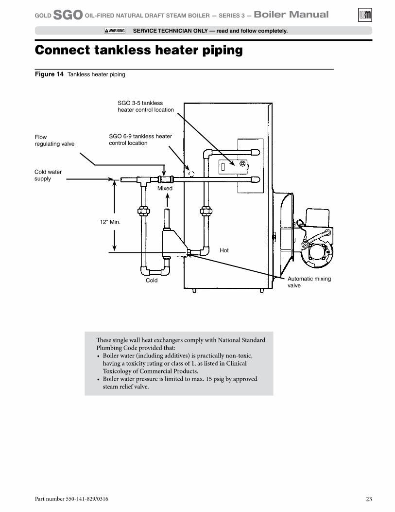
These single wall heat exchangers comply with National Standard Plumbing Code provided that:• Boiler water (including additives) is practically non-toxic,
having a toxicity rating or class of 1, as listed in Clinical Toxicology of Commercial Products.
• Boiler water pressure is limited to max. 15 psig by approved steam relief valve.
Figure 14 Tankless heater piping
SGO 3-5 tankless heater control location
SGO 6-9 tankless heater control location
Flow regulating valve
Automatic mixing valve
Mixed
Hot
Cold
Cold water supply
12" Min.
Connect tankless heater piping
Part number 550-141-829/0316 23
GOLD SGO OIL-FIRED NATURAL DRAFT STEAM BOILER — SERIES 3 — Boiler Manual
SERVICE TECHNICIAN ONLY — read and follow completely.
Connect wiring — general informationGeneral wiring requirements
Electric shock hazard. Can cause severe personal injury or death if power source, including service switch on boiler, is not disconnected before installing or servic-ing.
• Installations must follow these codes:• National Electrical Code, ANSI/NFPA 70, lat-
est edition and any additional national, state or local codes.
• In Canada, CSA C22.1 Canadian Electrical Code Part One and any local codes.
• Wiring must be N.E.C. Class 1. If original wire as supplied with boiler must be replaced, type 105°C wire or equivalent must be used. Supply wiring to boiler and additional control wiring must be 14 ga. or heavier.
• Provide electrical ground at boiler as required by codes.
Thermostat wiring• Install thermostat on inside wall away from influ-
ences of drafts, hot or cold water pipes, lighting fixtures, television, sun rays or fireplaces.
• Follow instructions with thermostat. If it has a heat anticipator, set heat anticipator in thermostat to match power requirements of equipment con-nected to it. Boiler wiring diagrams give setting for standard equipment.
Junction box (furnished)• Junction box houses electrical connections for all
boiler components.
• “P” boilers have harnesses furnished.
• “A” boilers are furnished with burner and limit harnesses.
• All field-provided high voltage wiring must be sheathed in flexible metal conduit.
• Connect incoming line voltage “HOT” wire to service switch, and neutral wire to white wire. Field-install equipment ground wire to green wire with wire nut.
• Service switch (15 amp) is provided with boiler. “A” boilers — install switch as shown.
• Some local codes may require an emergency shut-off switch installed at a location away from boiler. Follow local codes.
Burner wiring• Burner harness incorporates a disconnect plug,
providing a convenient way to disconnect wiring when burner mounting door is opened.
• All “P” boilers have a power disconnect plug in-stalled on burner.
• On “A” boilers, mount the plug (provided in steam trim carton) on the burner housing as shown in Figure 18, page 27, or Figure 20, page 29. For Carlin burners, screw burner plug into threaded conduit coupling, then mount this assembly to the burner housing using the chase nipple. Route wires through housing and make connections in burner junction box as shown in boiler wiring diagram.
High temperature limit• To comply with ASME, UL 726 or Canadian re-
quirements, an additional high temperature limit is needed.
• Install the secondary control in the supply piping between boiler and isolation valve.
• Set the control to a minimum of 20˚F above the set point of the combination control.
• The maximum allowable set point is 220˚F.
• Wire the control as shown on page 26 (float-type LWCO) or page 28 (probe-type LWCO).
Part number 550-141-829/031624
GOLD SGO OIL-FIRED NATURAL DRAFT STEAM BOILER — SERIES 3 — Boiler Manual
SERVICE TECHNICIAN ONLY — read and follow completely.
Connect wiring — general information (continued)
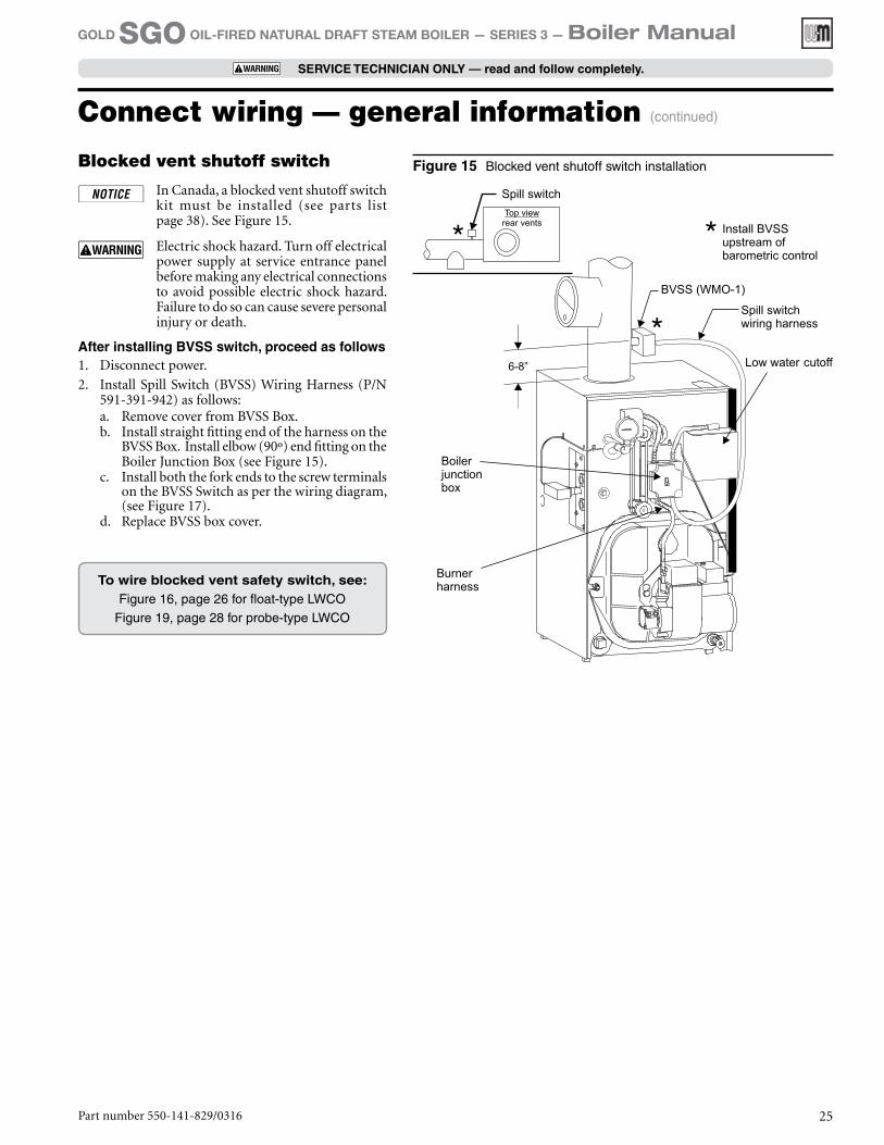
Figure 15 Blocked vent shutoff switch installationBlocked vent shutoff switch
In Canada, a blocked vent shutoff switch kit must be installed (see parts list page 38). See Figure 15.
Electric shock hazard. Turn off electrical power supply at service entrance panel before making any electrical connections to avoid possible electric shock hazard. Failure to do so can cause severe personal injury or death.
After installing BVSS switch, proceed as follows1. Disconnect power.
2. Install Spill Switch (BVSS) Wiring Harness (P/N 591-391-942) as follows:a. Remove cover from BVSS Box.b. Install straight fitting end of the harness on the
BVSS Box. Install elbow (90º) end fitting on the Boiler Junction Box (see Figure 15).
c. Install both the fork ends to the screw terminals on the BVSS Switch as per the wiring diagram, (see Figure 17).
d. Replace BVSS box cover.
To wire blocked vent safety switch, see:Figure 16, page 26 for float-type LWCO
Figure 19, page 28 for probe-type LWCO
Part number 550-141-829/0316 25
GOLD SGO OIL-FIRED NATURAL DRAFT STEAM BOILER — SERIES 3 — Boiler Manual
SERVICE TECHNICIAN ONLY — read and follow completely.
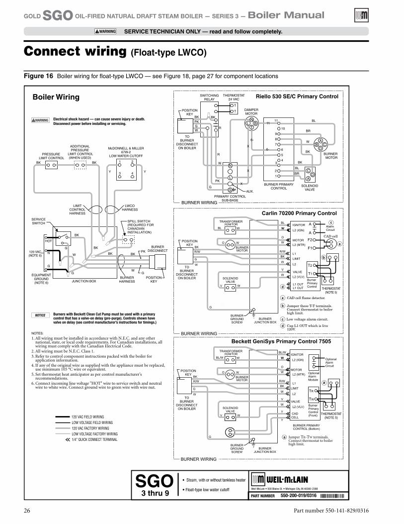
Connect wiring (Float-type LWCO)
Figure 16 Boiler wiring for float-type LWCO — see Figure 18, page 27 for component locations
Part number 550-141-829/031626
GOLD SGO OIL-FIRED NATURAL DRAFT STEAM BOILER — SERIES 3 — Boiler Manual
SERVICE TECHNICIAN ONLY — read and follow completely.
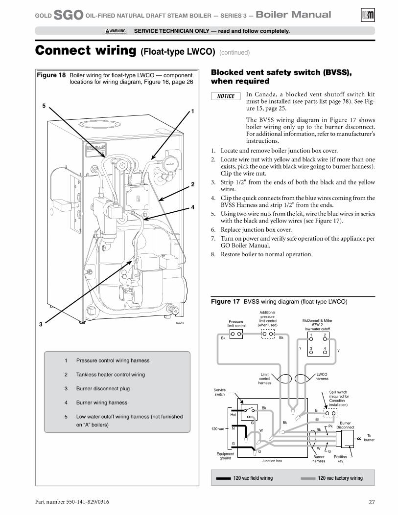
Figure 18 Boiler wiring for float-type LWCO — component locations for wiring diagram, Figure 16, page 26
Blocked vent safety switch (BVSS), when required
In Canada, a blocked vent shutoff switch kit must be installed (see parts list page 38). See Fig-ure 15, page 25.
The BVSS wiring diagram in Figure 17 shows boiler wiring only up to the burner disconnect. For additional information, refer to manufacturer’s instructions.
1. Locate and remove boiler junction box cover.
2. Locate wire nut with yellow and black wire (if more than one exists, pick the one with black wire going to burner harness). Clip the wire nut.
3. Strip 1/2" from the ends of both the black and the yellow wires.
4. Clip the quick connects from the blue wires coming from the BVSS Harness and strip 1/2" from the ends.
5. Using two wire nuts from the kit, wire the blue wires in series with the black and yellow wires (see Figure 17).
6. Replace junction box cover.
7. Turn on power and verify safe operation of the appliance per GO Boiler Manual.
8. Restore boiler to normal operation.
Connect wiring (Float-type LWCO) (continued)
Figure 17 BVSS wiring diagram (float-type LWCO)
120 vac field wiring 120 vac factory wiring
1
3
4
2
5
1 Pressure control wiring harness
2 Tankless heater control wiring
3 Burner disconnect plug
4 Burner wiring harness
5 Low water cutoff wiring harness (not furnished
on “A” boilers)
Part number 550-141-829/0316 27
GOLD SGO OIL-FIRED NATURAL DRAFT STEAM BOILER — SERIES 3 — Boiler Manual
SERVICE TECHNICIAN ONLY — read and follow completely.
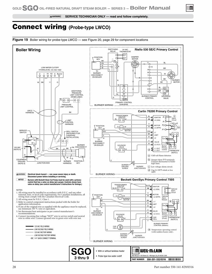
Connect wiring (Probe-type LWCO)
Figure 19 Boiler wiring for probe-type LWCO — see Figure 20, page 29 for component locations
Part number 550-141-829/031628
GOLD SGO OIL-FIRED NATURAL DRAFT STEAM BOILER — SERIES 3 — Boiler Manual
SERVICE TECHNICIAN ONLY — read and follow completely.
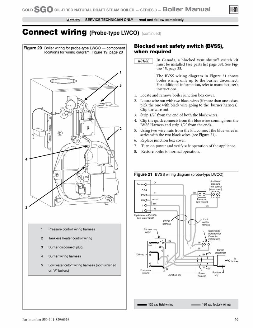
Figure 20 Boiler wiring for probe-type LWCO — component locations for wiring diagram, Figure 19, page 28
Connect wiring (Probe-type LWCO) (continued)
1
3
4
5
2
1 Pressure control wiring harness
2 Tankless heater control wiring
3 Burner disconnect plug
4 Burner wiring harness
5 Low water cutoff wiring harness (not furnished
on “A” boilers)
120 vac field wiring 120 vac factory wiring
Figure 21 BVSS wiring diagram (probe-type LWCO)
Part number 550-141-829/0316 29
GOLD SGO OIL-FIRED NATURAL DRAFT STEAM BOILER — SERIES 3 — Boiler Manual
SERVICE TECHNICIAN ONLY — read and follow completely.
Blocked vent safety switch (BVSS), when required
In Canada, a blocked vent shutoff switch kit must be installed (see parts list page 38). See Fig-ure 15, page 25.
The BVSS wiring diagram in Figure 21 shows boiler wiring only up to the burner disconnect. For additional information, refer to manufacturer’s instructions.
1. Locate and remove boiler junction box cover.
2. Locate wire nut with two black wires (if more than one exists, pick the one with black wire going to the burner harness). Clip the wire nut.
3. Strip 1/2" from the end of both the black wires.
4. Clip the quick connects from the blue wires coming from the BVSS Harness and strip 1/2" from the ends.
5. Using two wire nuts from the kit, connect the blue wires in series with the two black wires (see Figure 21).
6. Replace junction box cover.
7. Turn on power and verify safe operation of the appliance.
8. Restore boiler to normal operation.
General oil piping requirements• Location and installation of oil tanks, oil piping
and burners must follow:• NFPA 31, Standard for the Installation of Oil-
Burning Equipment.• In Canada, CSA B139, Installation of Oil-
Burning Equipment.• Local codes and regulations.• Information provided with burner and
fuel pump.• If any part of fuel oil tank is above level of burner,
installation of an anti-siphon device is highly recommended to prevent flow of oil in case of oil line break.
• Support oil lines as required by codes.
• Make tank connections with swing joints or copper tubing to prevent breaking in case the tank settles. Make swing joints so they will tighten as tank settles. Non-hardening pipe joint compounds should be used on all threads.
Do not use Teflon tape as an oil pipe sealant. It can cause valves to fail, creating hazards. Do not use compression fittings, only flare fittings.
• Underground pipe must be run in a casing to pre-vent oil leaking into ground or under floor. Check local codes for information.
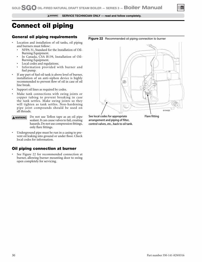
Oil piping connection at burner• See Figure 22 for recommended connection at
burner, allowing burner mounting door to swing open completely for servicing.
Figure 22 Recommended oil piping connection to burner
Part number 550-141-829/031630
GOLD SGO OIL-FIRED NATURAL DRAFT STEAM BOILER — SERIES 3 — Boiler Manual
SERVICE TECHNICIAN ONLY — read and follow completely.
Connect oil piping

Part number 550-141-829/0316 31
GOLD SGO OIL-FIRED NATURAL DRAFT STEAM BOILER — SERIES 3 — Boiler Manual
SERVICE TECHNICIAN ONLY — read and follow completely.
Fill the system1. Do not fill (except for leakage tests) until boiler is
ready to be fired.
2. Fill to normal water line as indicated on jacket front panel.
3. Boiler water pH 7.0 to 8.5 is recommended.
Failure to maintain recommended pH level can cause section failure and leaks.
4. Follow “Skim steam boiler” to assure proper op-eration.
Tips for steam systems• Check boiler and system piping for leaks. Continual
makeup water will reduce boiler life. Minerals can build up in sections, reducing heat transfer and caus-ing cast iron to overheat, resulting in section failure.
Failure to maintain recommended pH and repair leaks can cause section iron corrosion, leading to section failure and leaks. Do not use petroleum-based seal-ing or stop-leak compounds in boiler system. Damage to system components can result.
• For pH conditions outside 7.0 to 8.5 range or un-usually hard water areas (above 7 grains hardness), consult local water treatment company.
Skim steam boiler
Clean new steam boilers to remove any impurities. Failure to properly clean can result in violent water level fluctuations, water passing into steam mains, or high maintenance costs on strainers, traps or vents. Skim boiler only. Do not clean old piping or leaks can occur.
Do not use petroleum-based compounds in boiler system. Damage to system components can result, causing property damage.
1. Provide 1½" skim piping from skim tapping to floor drain. Add a tee in piping to observe skim water level. Raise waterline to midpoint of skim tapping.
2. Fire burner to maintain water temperature below steaming temperature during skimming process.
3. Feed in water to maintain water level. Cycle burner to prevent rise in steam pressure. Continue skim-ming until discharge is clear.
4. While boiler is warm, but not hot, drain boiler through drain valve.
5. Remove skim piping. Close drain valve. Fill with fresh water to normal waterline. Start burner and steam for 15 minutes to remove dissolved gases. Stop burner.
6. Check traps and air vents for proper operation.
7. Process may need to be repeated after several weeks of operation.
To place in operation1. Verify boiler is filled with water to normal waterline
as indicated on jacket front panel.
2. Open burner door and verify rear target wall, floor and burner door insulations are in proper position and condition.
3. Verify burner mounting door is closed tightly and burner wiring harness is connected to junction box.
4. Factory burner adjustment and settings may not be suitable for specific job conditions. See “Burner adjustments for packaged and non-packaged boil-ers” on page 36.
Make final burner adjustments using combustion test equipment to assure proper operation. Do not fire boiler without water. Sections will overheat, damaging boiler and resulting in sub-stantial property damage.
5. Check boiler and system piping for leaks. See “Tips for steam systems.”
6. Inspect breeching and venting for proper operation.
Start up
Part number 550-141-829/031632
GOLD SGO OIL-FIRED NATURAL DRAFT STEAM BOILER — SERIES 3 — Boiler Manual
SERVICE TECHNICIAN ONLY — read and follow completely.
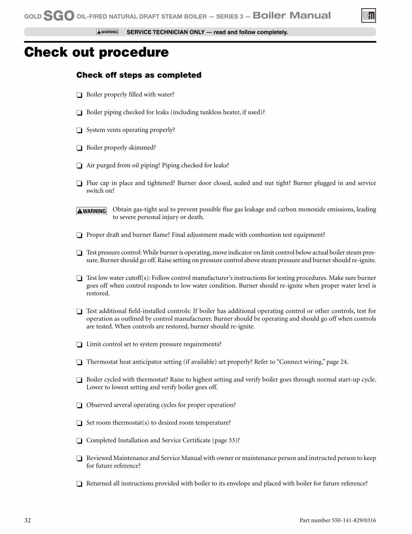
Check off steps as completed
❏❏ Boiler properly filled with water?
❏❏ Boiler piping checked for leaks (including tankless heater, if used)?
❏❏ System vents operating properly?
❏❏ Boiler properly skimmed?
❏❏ Air purged from oil piping? Piping checked for leaks?
❏❏ Flue cap in place and tightened? Burner door closed, sealed and nut tight? Burner plugged in and service switch on?
Obtain gas-tight seal to prevent possible flue gas leakage and carbon monoxide emissions, leading to severe personal injury or death.
❏❏ Proper draft and burner flame? Final adjustment made with combustion test equipment?
❏❏ Test pressure control: While burner is operating, move indicator on limit control below actual boiler steam pres-sure. Burner should go off. Raise setting on pressure control above steam pressure and burner should re-ignite.
❏❏ Test low water cutoff(s): Follow control manufacturer’s instructions for testing procedures. Make sure burner goes off when control responds to low water condition. Burner should re-ignite when proper water level is restored.
❏❏ Test additional field-installed controls: If boiler has additional operating control or other controls, test for operation as outlined by control manufacturer. Burner should be operating and should go off when controls are tested. When controls are restored, burner should re-ignite.
❏❏ Limit control set to system pressure requirements?
❏❏ Thermostat heat anticipator setting (if available) set properly? Refer to “Connect wiring,” page 24.
❏❏ Boiler cycled with thermostat? Raise to highest setting and verify boiler goes through normal start-up cycle. Lower to lowest setting and verify boiler goes off.
❏❏ Observed several operating cycles for proper operation?
❏❏ Set room thermostat(s) to desired room temperature?
❏❏ Completed Installation and Service Certificate (page 33)?
❏❏ Reviewed Maintenance and Service Manual with owner or maintenance person and instructed person to keep for future reference?
❏❏ Returned all instructions provided with boiler to its envelope and placed with boiler for future reference?
Check out procedure
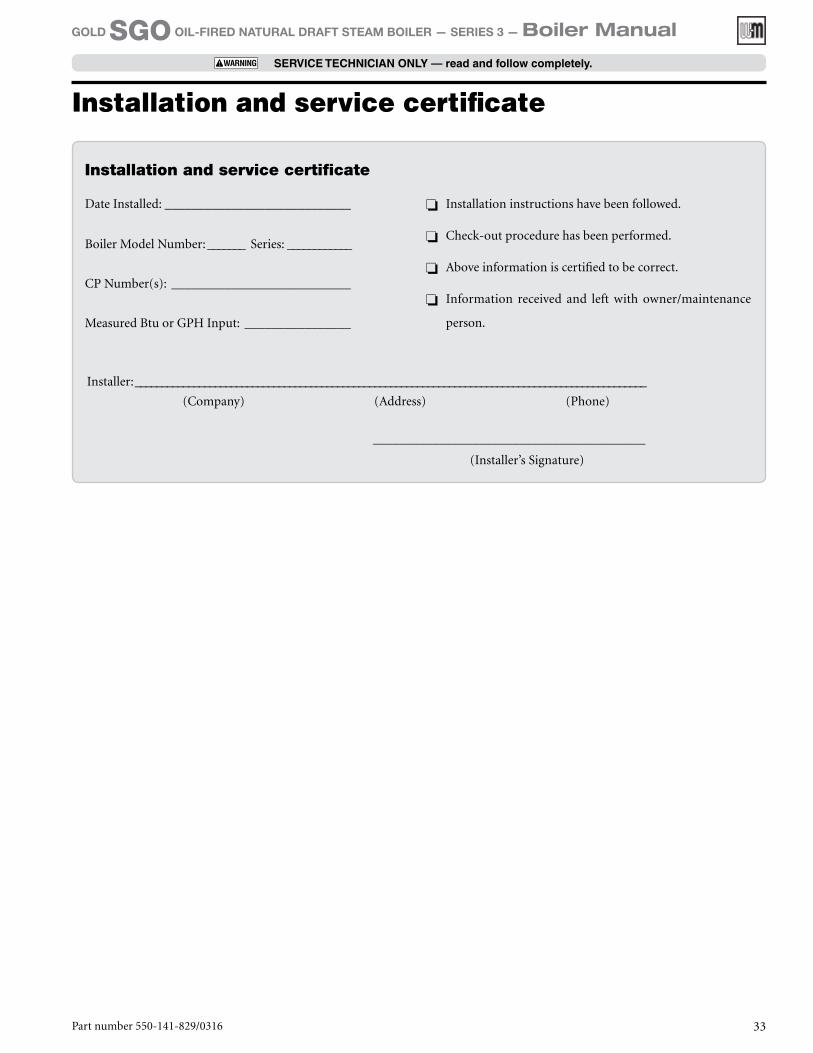
Date Installed: ____________________________
Boiler Model Number: _______ Series: ____________
CP Number(s): ___________________________
Measured Btu or GPH Input: ________________
❏❏ Installation instructions have been followed.
❏❏ Check-out procedure has been performed.
❏❏ Above information is certified to be correct.
❏❏ Information received and left with owner/maintenance
person.
Installation and service certificate
Installer: ________________________________________________________________________________________________
(Company) (Address) (Phone)
_________________________________________
(Installer’s Signature)
Part number 550-141-829/0316 33
GOLD SGO OIL-FIRED NATURAL DRAFT STEAM BOILER — SERIES 3 — Boiler Manual
SERVICE TECHNICIAN ONLY — read and follow completely.
Installation and service certificate
Part number 550-141-829/031634
GOLD SGO OIL-FIRED NATURAL DRAFT STEAM BOILER — SERIES 3 — Boiler Manual
SERVICE TECHNICIAN ONLY — read and follow completely.
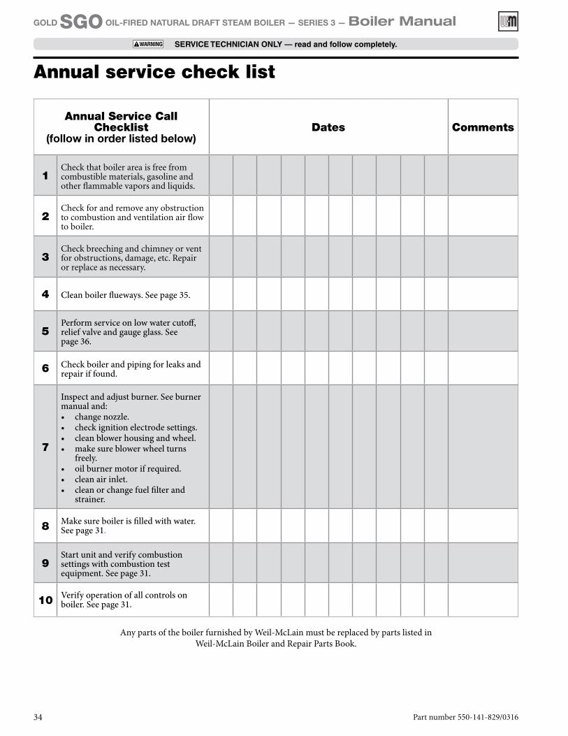
Annual service check list
Annual Service Call Checklist
(follow in order listed below)Dates Comments
1Check that boiler area is free from combustible materials, gasoline and other flammable vapors and liquids.
2Check for and remove any obstruction to combustion and ventilation air flow to boiler.
3Check breeching and chimney or vent for obstructions, damage, etc. Repair or replace as necessary.
4 Clean boiler flueways. See page 35.
5Perform service on low water cutoff, relief valve and gauge glass. See page 36.
6 Check boiler and piping for leaks and repair if found.
7
Inspect and adjust burner. See burner manual and:• change nozzle.• check ignition electrode settings.• clean blower housing and wheel.• make sure blower wheel turns
freely.• oil burner motor if required.• clean air inlet.• clean or change fuel filter and
strainer.
8 Make sure boiler is filled with water. See page 31.
9Start unit and verify combustion settings with combustion test equipment. See page 31.
10 Verify operation of all controls on boiler. See page 31.
Any parts of the boiler furnished by Weil-McLain must be replaced by parts listed in Weil-McLain Boiler and Repair Parts Book.
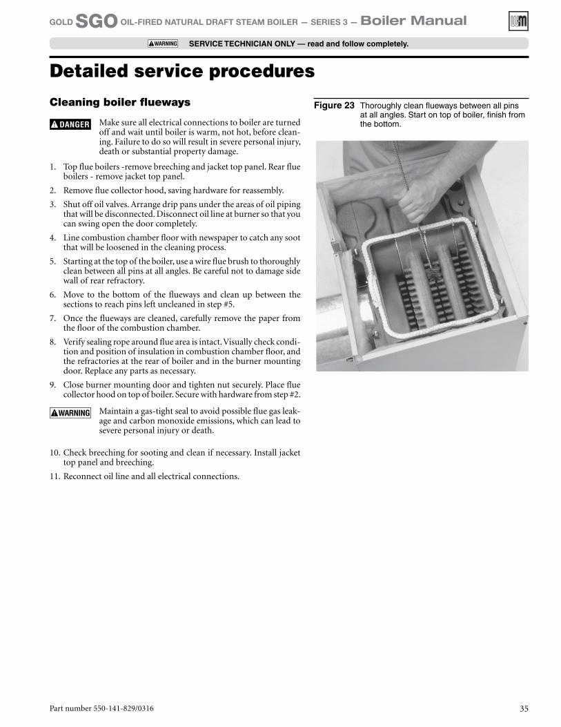
Figure 23 Thoroughly clean flueways between all pins at all angles. Start on top of boiler, finish from the bottom.
Part number 550-141-829/0316 35
GOLD SGO OIL-FIRED NATURAL DRAFT STEAM BOILER — SERIES 3 — Boiler Manual
SERVICE TECHNICIAN ONLY — read and follow completely.
Cleaning boiler flueways
Make sure all electrical connections to boiler are turned off and wait until boiler is warm, not hot, before clean-ing. Failure to do so will result in severe personal injury, death or substantial property damage.
1. Top flue boilers -remove breeching and jacket top panel. Rear flue boilers - remove jacket top panel.
2. Remove flue collector hood, saving hardware for reassembly.
3. Shut off oil valves. Arrange drip pans under the areas of oil piping that will be disconnected. Disconnect oil line at burner so that you can swing open the door completely.
4. Line combustion chamber floor with newspaper to catch any soot that will be loosened in the cleaning process.
5. Starting at the top of the boiler, use a wire flue brush to thoroughly clean between all pins at all angles. Be careful not to damage side wall of rear refractory.
6. Move to the bottom of the flueways and clean up between the sections to reach pins left uncleaned in step #5.
7. Once the flueways are cleaned, carefully remove the paper from the floor of the combustion chamber.
8. Verify sealing rope around flue area is intact. Visually check condi-tion and position of insulation in combustion chamber floor, and the refractories at the rear of boiler and in the burner mounting door. Replace any parts as necessary.
9. Close burner mounting door and tighten nut securely. Place flue collector hood on top of boiler. Secure with hardware from step #2.
Maintain a gas-tight seal to avoid possible flue gas leak-age and carbon monoxide emissions, which can lead to severe personal injury or death.
10. Check breeching for sooting and clean if necessary. Install jacket top panel and breeching.
11. Reconnect oil line and all electrical connections.
Detailed service procedures

Part number 550-141-829/031636
GOLD SGO OIL-FIRED NATURAL DRAFT STEAM BOILER — SERIES 3 — Boiler Manual
SERVICE TECHNICIAN ONLY — read and follow completely.
General description of control operation
Low water cutoff
Shuts down boiler if there is a low water condition.
Steam relief valve
Provides discharge if boiler pressure exceeds 15 psig.
Pressure limit control
If high steam pressure occurs, control shuts down burners until pressure drops. Limit should be set higher than design pressure of system. Operating control can be set at 5 psig and adjusted to comfort level. Normal operation is usually less than 5 psig. At certain times the system may operate under vacuum conditions.
Gauge glass
Indicates boiler water level. Cold fill water level should corre-spond to line stamped on boiler jacket. When boiler operates, water level will fluctuate.
Pressure gauge
Provides reading of boiler pressure. Maximum boiler pressure is 15 psig.
Tankless water heater
Weil-McLain tankless heater ratings are based on 200°F boiler water temperature. To get rated output, set tankless heater con-trol to 200°F. Control can be adjusted to meet system hot water requirements.
Burner adjustments for packaged and non-packaged boilers
Final burner adjustments must be made using combustion test equipment to assure proper opera-tion. Do not fire boiler without water or sections will overheat.
1. Refer to burner manual for start-up.
2. Allow boiler to heat to design condition.
3. Burner should be adjusted to 13% CO2 or less with a smoke
level of zero and over-fire of -0.01” to -0.02”. Re-adjust burner combustion to account for environmental conditions. Actual CO
2 value will vary and should be adjusted for clean and safe
combustion operation. Seasonal variations as well as suf-ficient combustion air supply can affect proper combustion and boiler performance. The burner should only be adjusted by a service professional with appropriate instrumentation.
Controls requiring annual service
Float-type low water cutoff
Follow instructions to blowdown cutoff on page 4. Also refer to instructions from cutoff manufacturer in envelope assembly provided with boiler.
Probe-type low water cutoff
Cutoff must be removed and inspected and cleaned annually. Refer to cutoff manufacturer’s instructions in envelope assembly provided with boiler.
Steam relief valve
Check operation of steam relief valve. Follow instructions on label fastened to relief valve.
Scald potential. Do not check operation of relief valve unless discharge piping has been installed ac-cording to Boiler Manual. If piping is not in place, a qualified service technician must properly install piping.
Gauge Glass
To clean glass:
1. Close lower gauge glass cock and carefully open petcock below glass to blow water and sediment out of glass by steam pressure.
2. Slowly open lower gauge glass cock and allow a small amount of water to flush out through the open petcock.
3. Close petcock and fully open lower gauge cock. The water level should immediately rise to its proper level.
4. If gauge glass breaks, close off both gauge cocks and loosen glass retaining nuts to remove gauge glass. Do not use thin glass tubing as a replacement.
Detailed service procedures (continued)

Part number 550-141-829/0316 37
GOLD SGO OIL-FIRED NATURAL DRAFT STEAM BOILER — SERIES 3 — Boiler Manual
SERVICE TECHNICIAN ONLY — read and follow completely.
REMOVAL OF COMBUSTION CHAMBER LINING OR BASE PANELS
The combustion chamber lining or base insu-lation panels in this product contain ceramic fiber materials that have been identified as car-cinogenic, or possibly carcinogenic, to humans. Ceramic fibers can be converted to cristobalite in very high temperature applications. The International Agency for Research on Cancer (IARC) has concluded, “Crystalline silica inhaled in the form of quartz or cristobalite from occupational sources is carcinogenic to humans (Group 1).”:
Precautionary measures ❏ Avoid breathing fiberglass dust and contact with
skin or eyes.• Use NIOSH certified dust respirator (N95).
This type of respirator is based on the OSHA requirements for fiberglass wool at the time this document was written. Other types of respirators may be needed depending on the job site conditions. Current NIOSH recom-mendations can be found on the NIOSH web site at http://www.cdc.gov/niosh/homepage.html. NIOSH approved respirators, manufac-turers, and phone numbers are also listed on this web site.
• Wear long-sleeved, loose fitting clothing, gloves, and eye protection.
❏ Apply enough water to the combustion chamber lining or base insulation to prevent airborne dust.
❏ Remove combustion chamber lining or base insula-tion from the boiler and place it in a plastic bag for disposal.
❏ Wash potentially contaminated clothes separately from other clothing. Rinse clothes washer thor-oughly.
NIOSH stated First Aid ❏ Eye: Irrigate immediately ❏ Breathing: Fresh air
REMOVAL OF FIBERGLASS WOOL
or
INSTALLATION OF FIBERGLASS WOOL
OR BASE PANELS:
This product contains fiberglass jacket insula-tion and ceramic fiber materials in combus-tion chamber lining or base panels in gas fired products. Airborne fibers from these materials have been listed by the State of California as a possible cause of cancer through inhalation.
Precautionary measures ❏ Avoid breathing fiberglass dust and contact with
skin or eyes.• Use NIOSH certified dust respirator (N95).
This type of respirator is based on the OSHA requirements for fiberglass wool at the time this document was written. Other types of respirators may be needed depending on the job site conditions. Current NIOSH recom-mendations can be found on the NIOSH web site at http://www.cdc.gov/niosh/homepage.html. NIOSH approved respirators, manu-facturers, and phone numbers are also listed on this web site.
• Wear long-sleeved, loose fitting clothing, gloves, and eye protection.
❏ Operations such as sawing, blowing, tear out, and spraying may generate airborne fiber concentration requiring additional protection.
❏ Wash potentially contaminated clothes separately from other clothing. Rinse clothes washer thor-oughly.
NIOSH stated First Aid ❏ Eye: Irrigate immediately ❏ Breathing: Fresh air
Handling ceramic fiber and fiberglass materials
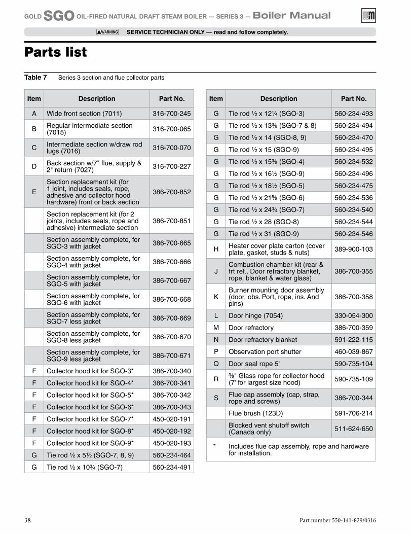
Parts list
Item Description Part No.
A Wide front section (7011) 316-700-245
B Regular intermediate section (7015) 316-700-065
C Intermediate section w/draw rod lugs (7016) 316-700-070
D Back section w/7" flue, supply & 2" return (7027) 316-700-227
E
Section replacement kit (for 1 joint, includes seals, rope, adhesive and collector hood hardware) front or back section
386-700-852
Section replacement kit (for 2 joints, includes seals, rope and adhesive) intermediate section
386-700-851
Section assembly complete, for SGO-3 with jacket 386-700-665
Section assembly complete, for SGO-4 with jacket 386-700-666
Section assembly complete, for SGO-5 with jacket 386-700-667
Section assembly complete, for SGO-6 with jacket 386-700-668
Section assembly complete, for SGO-7 less jacket 386-700-669
Section assembly complete, for SGO-8 less jacket 386-700-670
Section assembly complete, for SGO-9 less jacket 386-700-671
F Collector hood kit for SGO-3* 386-700-340
F Collector hood kit for SGO-4* 386-700-341
F Collector hood kit for SGO-5* 386-700-342
F Collector hood kit for SGO-6* 386-700-343
F Collector hood kit for SGO-7* 450-020-191
F Collector hood kit for SGO-8* 450-020-192
F Collector hood kit for SGO-9* 450-020-193
G Tie rod 1/2 x 51/2 (SGO-7, 8, 9) 560-234-464
G Tie rod 1/2 x 103/4 (SGO-7) 560-234-491
Item Description Part No.
G Tie rod 1/2 x 121/4 (SGO-3) 560-234-493
G Tie rod 1/2 x 133/8 (SGO-7 & 8) 560-234-494
G Tie rod 1/2 x 14 (SGO-8, 9) 560-234-470
G Tie rod 1/2 x 15 (SGO-9) 560-234-495
G Tie rod 1/2 x 153/8 (SGO-4) 560-234-532
G Tie rod 1/2 x 161/2 (SGO-9) 560-234-496
G Tie rod 1/2 x 181/2 (SGO-5) 560-234-475
G Tie rod 1/2 x 215/8 (SGO-6) 560-234-536
G Tie rod 1/2 x 243/4 (SGO-7) 560-234-540
G Tie rod 1/2 x 28 (SGO-8) 560-234-544
G Tie rod 1/2 x 31 (SGO-9) 560-234-546
H Heater cover plate carton (cover plate, gasket, studs & nuts) 389-900-103
JCombustion chamber kit (rear & frt ref., Door refractory blanket, rope, blanket & water glass)
386-700-355
KBurner mounting door assembly (door, obs. Port, rope, ins. And pins)
386-700-358
L Door hinge (7054) 330-054-300
M Door refractory 386-700-359
N Door refractory blanket 591-222-115
P Observation port shutter 460-039-867
Q Door seal rope 5' 590-735-104
R 3/8" Glass rope for collector hood (7' for largest size hood) 590-735-109
S Flue cap assembly (cap, strap, rope and screws) 386-700-344
Flue brush (123D) 591-706-214
Blocked vent shutoff switch (Canada only) 511-624-650
* Includes flue cap assembly, rope and hardware for installation.
Table 7 Series 3 section and flue collector parts
Part number 550-141-829/031638
GOLD SGO OIL-FIRED NATURAL DRAFT STEAM BOILER — SERIES 3 — Boiler Manual
SERVICE TECHNICIAN ONLY — read and follow completely.
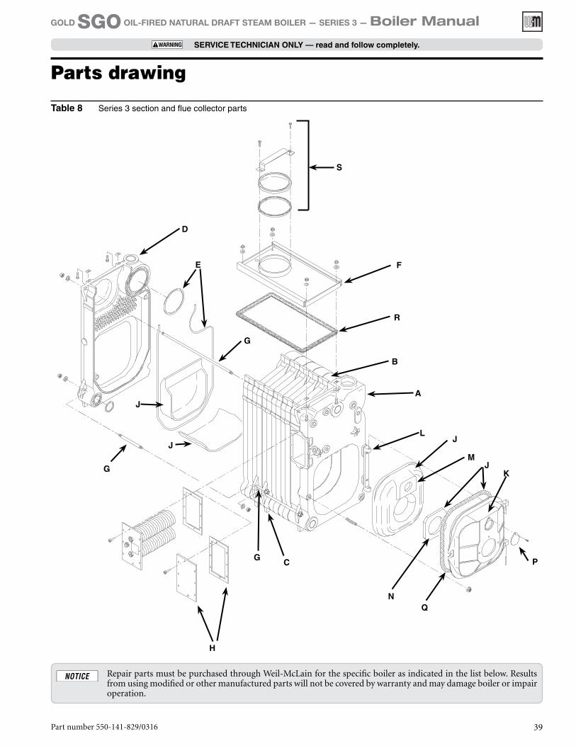
Repair parts must be purchased through Weil-McLain for the specific boiler as indicated in the list below. Results from using modified or other manufactured parts will not be covered by warranty and may damage boiler or impair operation.
D
JK
J
J
CG
G
NQ
E
G
F
R
B
A
P
LJ
M
H
S
Parts drawing
Table 8 Series 3 section and flue collector parts
Part number 550-141-829/0316 39
GOLD SGO OIL-FIRED NATURAL DRAFT STEAM BOILER — SERIES 3 — Boiler Manual
SERVICE TECHNICIAN ONLY — read and follow completely.
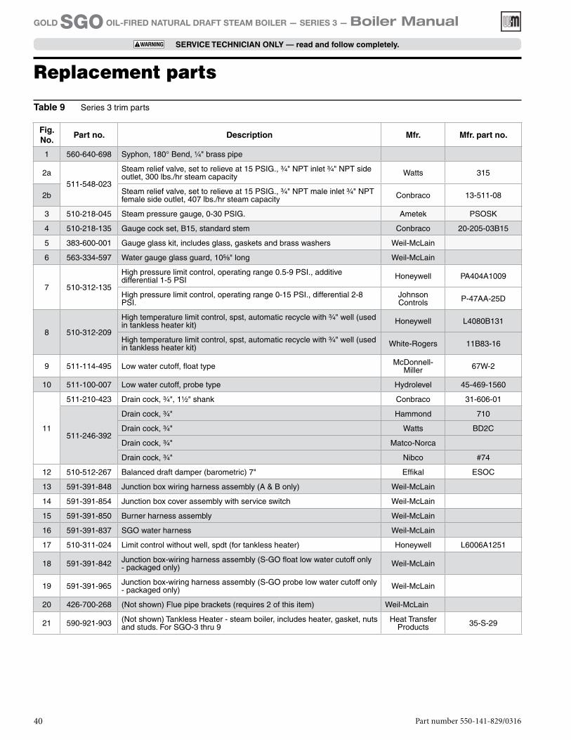
Fig. No.
Part no. Description Mfr. Mfr. part no.
1 560-640-698 Syphon, 180° Bend, 1/4" brass pipe
2a511-548-023
Steam relief valve, set to relieve at 15 PSIG., 3/4" NPT inlet 3/4" NPT side outlet, 300 lbs./hr steam capacity Watts 315
2b Steam relief valve, set to relieve at 15 PSIG., 3/4" NPT male inlet 3/4" NPT female side outlet, 407 lbs./hr steam capacity Conbraco 13-511-08
3 510-218-045 Steam pressure gauge, 0-30 PSIG. Ametek PSOSK
4 510-218-135 Gauge cock set, B15, standard stem Conbraco 20-205-03B15
5 383-600-001 Gauge glass kit, includes glass, gaskets and brass washers Weil-McLain
6 563-334-597 Water gauge glass guard, 105/8" long Weil-McLain
7 510-312-135
High pressure limit control, operating range 0.5-9 PSI., additive differential 1-5 PSI Honeywell PA404A1009
High pressure limit control, operating range 0-15 PSI., differential 2-8 PSI.
Johnson Controls P-47AA-25D
8 510-312-209
High temperature limit control, spst, automatic recycle with 3/4" well (used in tankless heater kit) Honeywell L4080B131
High temperature limit control, spst, automatic recycle with 3/4" well (used in tankless heater kit) White-Rogers 11B83-16
9 511-114-495 Low water cutoff, float type McDonnell-Miller 67W-2
10 511-100-007 Low water cutoff, probe type Hydrolevel 45-469-1560
11
511-210-423 Drain cock, 3/4", 11/2" shank Conbraco 31-606-01
511-246-392
Drain cock, 3/4" Hammond 710
Drain cock, 3/4" Watts BD2C
Drain cock, 3/4" Matco-Norca
Drain cock, 3/4" Nibco #74
12 510-512-267 Balanced draft damper (barometric) 7" Effikal ESOC
13 591-391-848 Junction box wiring harness assembly (A & B only) Weil-McLain
14 591-391-854 Junction box cover assembly with service switch Weil-McLain
15 591-391-850 Burner harness assembly Weil-McLain
16 591-391-837 SGO water harness Weil-McLain
17 510-311-024 Limit control without well, spdt (for tankless heater) Honeywell L6006A1251
18 591-391-842 Junction box-wiring harness assembly (S-GO float low water cutoff only - packaged only) Weil-McLain
19 591-391-965 Junction box-wiring harness assembly (S-GO probe low water cutoff only - packaged only) Weil-McLain
20 426-700-268 (Not shown) Flue pipe brackets (requires 2 of this item) Weil-McLain
21 590-921-903 (Not shown) Tankless Heater - steam boiler, includes heater, gasket, nuts and studs. For SGO-3 thru 9
Heat Transfer Products 35-S-29
Table 9 Series 3 trim parts
Part number 550-141-829/031640
GOLD SGO OIL-FIRED NATURAL DRAFT STEAM BOILER — SERIES 3 — Boiler Manual
SERVICE TECHNICIAN ONLY — read and follow completely.
Replacement parts
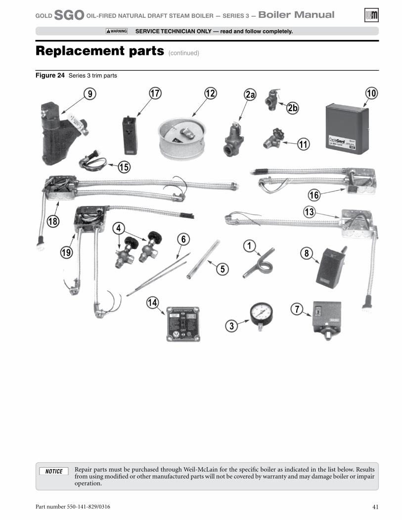
Figure 24 Series 3 trim parts
Repair parts must be purchased through Weil-McLain for the specific boiler as indicated in the list below. Results from using modified or other manufactured parts will not be covered by warranty and may damage boiler or impair operation.
Part number 550-141-829/0316 41
GOLD SGO OIL-FIRED NATURAL DRAFT STEAM BOILER — SERIES 3 — Boiler Manual
SERVICE TECHNICIAN ONLY — read and follow completely.
Replacement parts (continued)
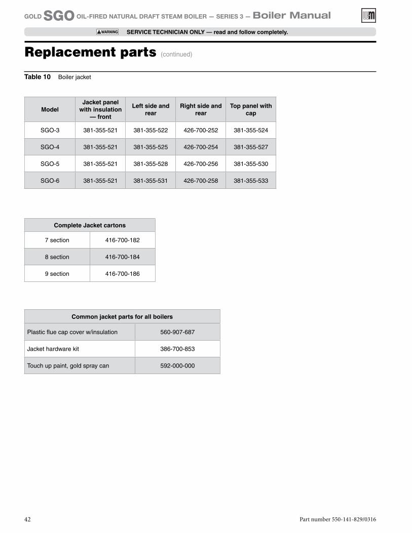
Part number 550-141-829/031642
GOLD SGO OIL-FIRED NATURAL DRAFT STEAM BOILER — SERIES 3 — Boiler Manual
SERVICE TECHNICIAN ONLY — read and follow completely.
ModelJacket panel
with insulation — front
Left side and rear
Right side and rear
Top panel with cap
SGO-3 381-355-521 381-355-522 426-700-252 381-355-524
SGO-4 381-355-521 381-355-525 426-700-254 381-355-527
SGO-5 381-355-521 381-355-528 426-700-256 381-355-530
SGO-6 381-355-521 381-355-531 426-700-258 381-355-533
Complete Jacket cartons
7 section 416-700-182
8 section 416-700-184
9 section 416-700-186
Common jacket parts for all boilers
Plastic flue cap cover w/insulation 560-907-687
Jacket hardware kit 386-700-853
Touch up paint, gold spray can 592-000-000
Table 10 Boiler jacket
Replacement parts (continued)
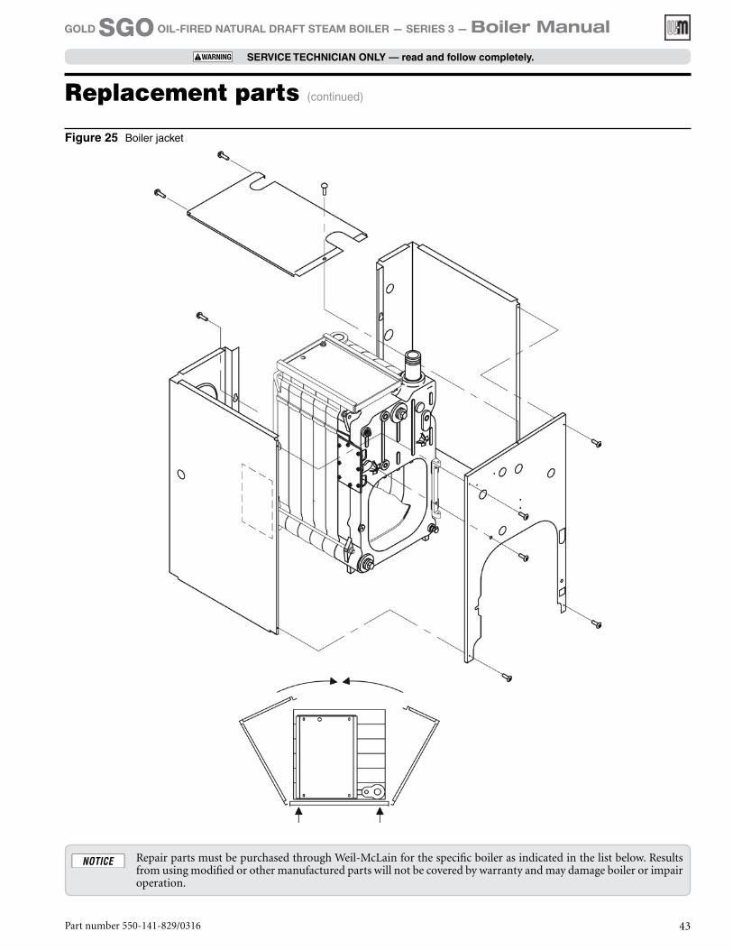
Figure 25 Boiler jacket
Repair parts must be purchased through Weil-McLain for the specific boiler as indicated in the list below. Results from using modified or other manufactured parts will not be covered by warranty and may damage boiler or impair operation.
Part number 550-141-829/0316 43
GOLD SGO OIL-FIRED NATURAL DRAFT STEAM BOILER — SERIES 3 — Boiler Manual
SERVICE TECHNICIAN ONLY — read and follow completely.
Replacement parts (continued)
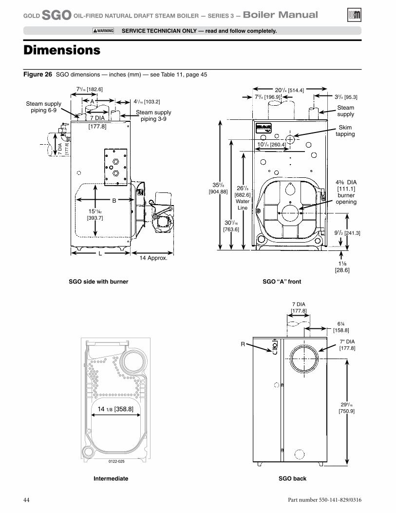
Steam supply
Skim tapping
73/4 [196.9]
101/4 [260.4]
11/8 [28.6]
33/4 [95.3]
43/8 DIA [111.1] burner
opening
SGO “A” front
201/4 [514.4]
91/2 [241.3]
355/8
[904.88]267/8
[682.6]Water Line
301/16
[763.6]
SGO back
6¼
[158.8]
7" DIA
[177.8]R
7 DIA
[177.8]
299/16
[750.9]
Intermediate
SGO side with burner
Steam supplypiping 3-9
Steam supplypiping 6-9
73/16 [182.6]
41/16 [103.2]
14 Approx.
7 D
IA
[177
.8]
A
7 DIA [177.8]
151¼2
[393.7]
L
B
Figure 26 SGO dimensions — inches (mm) — see Table 11, page 45
Dimensions
Part number 550-141-829/031644
GOLD SGO OIL-FIRED NATURAL DRAFT STEAM BOILER — SERIES 3 — Boiler Manual
SERVICE TECHNICIAN ONLY — read and follow completely.
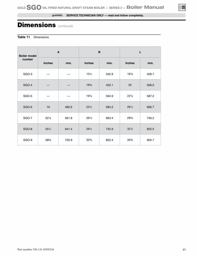
Table 11 Dimensions
Part number 550-141-829/0316 45
GOLD SGO OIL-FIRED NATURAL DRAFT STEAM BOILER — SERIES 3 — Boiler Manual
SERVICE TECHNICIAN ONLY — read and follow completely.
Boiler model number
A B L
Inches mm. Inches mm. Inches mm.
SGO-3 — — 131/2 342.9 167/8 428.7
SGO-4 — — 165/8 422.1 20 508.0
SGO-5 — — 197/8 504.9 221/8 587.2
SGO-6 19 482.6 231/2 584.2 261/4 666.7
SGO-7 221/8 561.8 261/8 663.4 293/8 746.2
SGO-8 251/4 641.4 291/4 742.9 321/2 825.5
SGO-9 283/8 720.9 323/8 822.4 355/8 904.7
Dimensions (continued)

Part number 550-141-829/031646
GOLD SGO OIL-FIRED NATURAL DRAFT STEAM BOILER — SERIES 3 — Boiler Manual
SERVICE TECHNICIAN ONLY — read and follow completely.
AHRI Certified Rating
BoilerModel
Number
BurnerCapacityGPH (3)
HeatingCapacity MBH (2, 4)
NetRatings (5)
Seasonal Efficiency
% AFUE
Minimum Chimney
Dimensions
Round Flue
OutletSize In (1, 7)
SteamBoilerWater
Content Gal (8)
DraftLossThru
Boiler In
W.C.(9)Steamsq. ft.
Steam MBH
RectIn
RoundIn
Height Ft
*-SGO-3 0.95 114 354 85 84.0 8x8 6 15 7 10.7 .020
*-SGO-4 1.20 144 450 108 84.0 8x8 6 15 7 12.5 .010
*-SGO-5 1.45 174 546 131 83.9 8x8 7 15 7 14.2 .015
*-SGO-6 1.75 210 658 158 83.7 8x8 7 15 7 16 .015
**-SGO-7 2.00 240 750 180 83.6 8x8 8 15 7 17.7 .015
**-SGO-8 2.30 266 (6) 833 200 — 8x12 8 20 7 19.4 .025
**-SGO-9 2.55 295 (6) 921 221 — 8x12 8 20 7 21.2 .030
* Substitute “P” for completely assembled packaged steam boiler without burner (SGO-3 through SGO-6 only). Substitute “A” for boiler only for use with approved burners as listed with AHRI.** Available only as an “A” unit.
(1) SGO boiler designed with convertible vertical and horizontal flue outlet.(2) MBH refers to thousands of Btu per hour.(3) Based on 140,000 Btu/gal.(4) Based on standard test procedures prescribed by the United States Department of Energy at combustion condition of 13.5% CO2
and -0.02” W.C. draft overfire .(5) Net ratings are based on net installed radiation of sufficient quantity for the requirements of the building and nothing need
be added for normal piping and pick-up. Steam ratings are based on a piping and pick-up allowance of 1.33. An additional allowance should be made for unusual piping and pick-up loads. Consult local Weil-McLain Sales Office.
(6) Gross output(7) See page 12 for minimum breeching diameter.(8) To water line.(9) Listed draft losses are for factory-shipped settings.
Ratings
Table 12 SGO GOLD Oil steam boiler ratings
DOE®
Notes
Part number 550-141-829/0316 47
GOLD SGO OIL-FIRED NATURAL DRAFT STEAM BOILER — SERIES 3 — Boiler Manual
SERVICE TECHNICIAN ONLY — read and follow completely.

Part number 550-141-829/0316
GOLD SGO OIL-FIRED NATURAL DRAFT STEAM BOILER — SERIES 3 — Boiler Manual