book 2- energy efficiency in thermal utilities...
TRANSCRIPT

Table of ContentsChapter
1 FUELS AND COMBUSTION
1.1 Introduction to Fuels 01
1.2 Properties of Liquid Fuels 01
1.3 Properties of Coal 06
1.4 Properties of Gaseous Fuels 12
1.5 Properties of Agro Residues 14
1.6 Combustion 15
1.7 Combustion of Oil 16
1.8 Combustion of Coal 22
1.9 Combustion of Gas 22
1.10 Draft System 24
1.11 Combustion Controls 25
2 BOILERS
2.1 Introduction 27
2.2 Boiler Systems 28
2.3 Boiler Types and Classifications 29
2.4 Performance Evaluation of Boilers 33
2.5 Boiler Blowdown 39
2.6 Boiler Water Treatment 41
2.7 Energy Conservation Opportunities 47
2.8 Case Study 52
BOOK 2- ENERGY EFFICIENCY IN THERMAL UTILITIES
FM.qxd 2/23/2005 11:15 AM Page 11

3 STEAM SYSTEM
3.1 Introduction 55
3.2 Properties of Steam 55
3.3 Steam Distribution 58
3.4 Steam Pipe Sizing and Design 59
3.5 Proper Selection, Operation and Maintenance of Steam Traps 62
3.6 Performance Assessment Methods for Steam Traps 73
3.7 Energy Saving Opportunities 75
4 FURNACES
4.1 Types and Classification of Different Furnaces 89
4.2 Performance Evaluation of a Typical Furnace 96
4.3 General Fuel Economy Measures in Furnaces 105
4.4 Case Study 117
5 INSULATION AND REFRACTORIES
5.1 Purpose of Insulation 120
5.2 Types and Application 120
5.3 Calculation of Insulation Thickness 122
5.4 Economic Thickness of Insulation(ETI) 124
5.5 Simplified Formula for Heat Loss Calculation 127
5.6 Refractories 128
5.7 Properties of Refractories 129
5.8 Classification of Refractories 131
5.9 Typical Refractories in Industrial Use 132
5.10 Selection of Refractories 139
5.11 Heat Losses from Furnace Walls 139
FM.qxd 2/23/2005 11:15 AM Page 12

6 FBC BOILERS
6.1 Introduction 143
6.2 Mechanism of Fluidised Bed Combustion 143
6.3 Types of Fluidised Bed Combustion Boilers 145
6.4 Retrofitting of FBC Systems to Conventional Boilers 151
6.5 Advantages of Fluidised Bed Combustion Boilers 152
7 COGENERATION
7.1 Need for Cogeneration 155
7.2 Principle of Cogeneration 155
7.3 Technical Options for Cogeneration 156
7.4 Classification of Cogeneration Systems 159
7.5 Factors Influencing Cogeneration Choice 160
7.6 Important Technical Parameters for Cogeneration 161
7.7 Prime Movers for Cogeneration 164
7.8 Typical Cogeneration Performance Parameters 168
7.9 Relative Merits of Cogeneration Systems 168
7.10 Case Study 169
8 WASTE HEAT RECOVERY
8.1 Introduction 173
8.2 Classification and Application 174
8.3 Benefits of Waste Heat Recovery 176
8.4 Development of a Waste Heat Recovery System 177
8.5 Commercial Waste Heat Recovery Devices 177
ANNEXURE
Checklists & Tips for Energy Efficiency in Thermal Utilities 190
FM.qxd 2/23/2005 11:15 AM Page 13

1. FUELS AND COMBUSTION
1Bureau of Energy Efficiency
Syllabus Introduction to Fuels, Properties of Fuel oil, Coal and Gas, Storage, handling andpreparation of fuels, Principles of Combustion, Combustion of Oil, Coal, and Gas
This chapter is a prelude to boilers and furnaces
1.1 Introduction to Fuels
The various types of fuels like liquid, solid and gaseous fuels are available for firing in boilers, furnaces and other combustion equipments. The selection of right type of fuel dependson various factors such as availability, storage, handling, pollution and landed cost of fuel.
The knowledge of the fuel properties helps in selecting the right fuel for the right purposeand efficient use of the fuel. The following characteristics, determined by laboratory tests, aregenerally used for assessing the nature and quality of fuels.
1.2 Properties of Liquid Fuels
Liquid fuels like furnace oil and LSHS are predominantly used in industrial application. The various properties of liquid fuels are given below.
Density
This is defined as the ratio of the mass of the fuel to the volume of the fuel at a reference tem-perature of 15°C. Density is measured by an instrument called hydrometer. The knowledge ofdensity is useful for quantity calculations and assessing ignition quality. The unit of density iskg/m3.
Specific gravity
This is defined as the ratio of the weight of a given volume of oil to the weight of the same volume of water at a given temperature. The density of fuel, relative to water, is called specific gravity. The specific gravity of water is defined as 1. Since specific gravity is a ratio,it has no units. The measurement of specific gravity is generally made by a hydrometer.
Specific gravity is used in calculations involving weights and volumes. The specific gravity of various fuel oils are given in Table 1.1
TABLE 1.1 SPECIFIC GRAVITY OF VARIOUS FUEL OILS
Fuel Oil L.D.O Furnace oil L.S.H.SLight Diesel Oil Low Sulphur
Heavy Stock
Specific Gravity 0.85-0.87 0.89-0.95 0.88-0.98
Ch-01.qxd 2/23/2005 11:18 AM Page 1
Viscosity
The viscosity of a fluid is a measure of its internal resistance to flow. Viscosity depends on temperature and decreases as the temperature increases. Any numerical value for viscosity hasno meaning unless the temperature is also specified. Viscosity is measured in Stokes /Centistokes. Sometimes viscosity is also quoted in Engler, Saybolt or Redwood. Each type ofoil has its own temperature - viscosity relationship. The measurement of viscosity is made withan instrument called Viscometer.
Viscosity is the most important characteristic in the storage and use of fuel oil. It influencesthe degree of pre-heat required for handling, storage and satisfactory atomization. If the oil istoo viscous, it may become difficult to pump, hard to light the burner, and tough to operate.Poor atomization may result in the formation of carbon deposits on the burner tips or on thewalls. Therefore pre-heating is necessary for proper atomization.
Flash Point
The flash point of a fuel is the lowest temperature at which the fuel can be heated so that thevapour gives off flashes momentarily when an open flame is passed over it. Flash point for furnace oil is 66°C.
Pour Point
The pour point of a fuel is the lowest temperature at which it will pour or flow when cooledunder prescribed conditions. It is a very rough indication of the lowest temperature at whichfuel oil is readily pumpable.
Specific Heat
Specific heat is the amount of kCals needed to raise the temperature of 1 kg of oil by 1°C. The unit of specific heat is kCal/kg°C. It varies from 0.22 to 0.28 depending on the oil specif-ic gravity. The specific heat determines how much steam or electrical energy it takes to heat oilto a desired temperature. Light oils have a low specific heat, whereas heavier oils have a high-er specific heat.
Calorific Value
The calorific value is the measurement of heat or energy produced, and is measured either asgross calorific value or net calorific value. The difference being the latent heat of condensationof the water vapour produced during the combustion process. Gross calorific value (GCV)assumes all vapour produced during the combustion process is fully condensed. Net calorificvalue (NCV) assumes the water leaves with the combustion products without fully being condensed. Fuels should be compared based on the net calorific value.
The calorific value of coal varies considerably depending on the ash, moisture content andthe type of coal while calorific value of fuel oils are much more consistent. The typical GrossCalorific Values of some of the commonly used liquid fuels are given below:
1. Fuels and Combustion
2Bureau of Energy Efficiency
Ch-01.qxd 2/23/2005 11:18 AM Page 2

Fuel Oil Gross Calorific Value (kCal/kg)Kerosene - 11,100 Diesel Oil - 10,800 L.D.O - 10,700 Furnace Oil - 10,500 LSHS - 10,600
Sulphur
The amount of sulphur in the fuel oil depends mainly on the source of the crude oil and to alesser extent on the refining process. The normal sulfur content for the residual fuel oil (furnaceoil) is in the order of 2-4 %.
Typical figures are:
Fuel oil Percentage of Sulphur
Kerosene 0.05 – 0.2Diesel Oil 0.05 – 0.25L.D.O 0.5 – 1.8Furnace Oil 2.0 – 4.0LSHS < 0.5
The main disadvantage of sulphur is the risk of corrosion by sulphuric acid formed during andafter combustion, and condensing in cool parts of the chimney or stack, air pre heater andeconomiser.
Ash Content
The ash value is related to the inorganic material in the fuel oil. The ash levels of distillate fuelsare negligible. Residual fuels have more of the ash-forming constituents. These salts may becompounds of sodium, vanadium, calcium, magnesium, silicon, iron, aluminum, nickel, etc.
Typically, the ash value is in the range 0.03–0.07%. Excessive ash in liquid fuels can causefouling deposits in the combustion equipment. Ash has erosive effect on the burner tips, causes damage to the refractories at high temperatures and gives rise to high temperature corrosion and fouling of equipments.
Carbon Residue
Carbon residue indicates the tendency of oil to deposit a carbonaceous solid residue on a hotsurface, such as a burner or injection nozzle, when its vaporisable constituents evaporate.Residual oil contain carbon residue ranging from 1 percent or more.
Water Content
Water content of furnace oil when supplied is normally very low as the product at refinery siteis handled hot and maximum limit of 1% is specified in the standard.
Water may be present in free or emulsified form and can cause damage to the inside furnacesurfaces during combustion especially if it contains dissolved salts. It can also cause splutter-ing of the flame at the burner tip, possibly extinguishing the flame and reducing the flame temperature or lengthening the flame.
1. Fuels and Combustion
3Bureau of Energy Efficiency
Ch-01.qxd 2/23/2005 11:18 AM Page 3

Typical specification of fuel oil is summarised in the Table 1.2.
1. Fuels and Combustion
4Bureau of Energy Efficiency
TABLE 1.2 TYPICAL SPECIFICATION OF FUEL OILS
PropertiesFurnace Oil LS.H.S. L.D.O.
Density (Approx. g/cc at 15°C) 0.89–0.95 0.88–0.98 0.85–0.87
Flash Point (°C) 66 93 66
Pour Point (°C) 20 72 18
G.C.V. (kCal/kg) 10,500 10,600 10,700
Sediment, % Wt. Max. 0.25 0.25 0.1
Sulphur Total, % Wt. Max. Upto 4.0 Upto 0.5 Upto 1.8
Water Content, % Vol. Max. 1.0 1.0 0.25
Ash % Wt. Max. 0.1 0.1 0.02
Storage of Fuel oil
It can be potentially hazardous to store furnace oil in barrels. A better practice is to store it incylindrical tanks, either above or below the ground. Furnace oil, that is delivered, may containdust, water and other contaminants.
The sizing of storage tank facility is very important. A recommended storage estimate is toprovide for at least 10 days of normal consumption. Industrial heating fuel storage tanks aregenerally vertical mild steel tanks mounted above ground. It is prudent for safety and environ-mental reasons to build bund walls around tanks to contain accidental spillages.
As a certain amount of settlement of solids and sludge will occur in tanks over time, cleaningshould be carried out at regular intervals-annually for heavy fuels and every two years for lightfuels. A little care should be taken when oil is decanted from the tanker to storage tank. All leaksfrom joints, flanges and pipelines must be attended at the earliest. Fuel oil should be free frompossible contaminants such as dirt, sludge and water before it is fed to the combustion system.
LOSS OF EVEN ONE DROP OF OIL EVERY SECOND CANCOST YOU OVER 4000 LITRES A YEAR
Removal of Contaminants
Furnace oil arrives at the factory site either in tank lorries by road or by rail. Oil is then decantedinto the main storage tank. To prevent contaminants such as rags, cotton waste, loose nuts orbolts or screws entering the system and damaging the pump, coarse strainer of 10 mesh size (notmore than 3 holes per linear inch) is positioned on the entry pipe to the storage tanks.
Progressively finer strainers should be provided at various points in the oil supply systemto filter away finer contaminants such as external dust and dirt, sludge or free carbon. It is advis-able to provide these filters in duplicate to enable one filter to be cleaned while oil supply ismaintained through the other.
Fuel Oils
Ch-01.qxd 2/23/2005 11:18 AM Page 4
1. Fuels and Combustion
5Bureau of Energy Efficiency
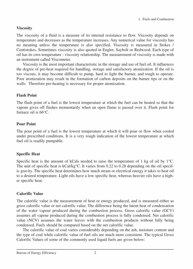
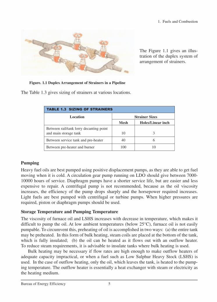
The Figure 1.1 gives an illus-tration of the duplex system ofarrangement of strainers.
The Table 1.3 gives sizing of strainers at various locations.
Pumping
Heavy fuel oils are best pumped using positive displacement pumps, as they are able to get fuelmoving when it is cold. A circulation gear pump running on LDO should give between 7000-10000 hours of service. Diaphragm pumps have a shorter service life, but are easier and lessexpensive to repair. A centrifugal pump is not recommended, because as the oil viscosityincreases, the efficiency of the pump drops sharply and the horsepower required increases.Light fuels are best pumped with centrifugal or turbine pumps. When higher pressures arerequired, piston or diaphragm pumps should be used.
Storage Temperature and Pumping Temperature
The viscosity of furnace oil and LSHS increases with decrease in temperature, which makes itdifficult to pump the oil. At low ambient temperatures (below 25°C), furnace oil is not easilypumpable. To circumvent this, preheating of oil is accomplished in two ways: (a) the entire tankmay be preheated. In this form of bulk heating, steam coils are placed at the bottom of the tank,which is fully insulated; (b) the oil can be heated as it flows out with an outflow heater. To reduce steam requirements, it is advisable to insulate tanks where bulk heating is used.
Bulk heating may be necessary if flow rates are high enough to make outflow heaters ofadequate capacity impractical, or when a fuel such as Low Sulphur Heavy Stock (LSHS) isused. In the case of outflow heating, only the oil, which leaves the tank, is heated to the pump-ing temperature. The outflow heater is essentially a heat exchanger with steam or electricity asthe heating medium.
TABLE 1.3 SIZING OF STRAINERS
Location Strainer Sizes
Mesh Holes/Linear inch
Between rail/tank lorry decanting point and main storage tank 10 3
Between service tank and pre-heater 40 6
Between pre-heater and burner 100 10
Figure. 1.1 Duplex Arrangement of Strainers in a Pipeline
Ch-01.qxd 2/23/2005 11:18 AM Page 5
Temperature Control
Thermostatic temperature control of the oil is necessary to prevent overheating, especiallywhen oil flow is reduced or stopped. This is particularly important for electric heaters,since oil may get carbonized when there is no flow and the heater is on. Thermostats shouldbe provided at a region where the oil flows freely into the suction pipe. The temperature atwhich oil can readily be pumped depends on the grade of oil being handled. Oil shouldnever be stored at a temperature above that necessary for pumping as this leads to higherenergy consumption.
1.3 Properties of Coal
Coal Classification
Coal is classified into three major types namely anthracite, bituminous, and lignite. Howeverthere is no clear demarcation between them and coal is also further classified as semi-anthracite, semi-bituminous, and sub-bituminous. Anthracite is the oldest coal from geologicalperspective. It is a hard coal composed mainly of carbon with little volatile content and practi-cally no moisture. Lignite is the youngest coal from geological perspective. It is a soft coal composed mainly of volatile matter and moisture content with low fixed carbon. Fixed carbonrefers to carbon in its free state, not combined with other elements. Volatile matter refers tothose combustible constituents of coal that vaporize when coal is heated.
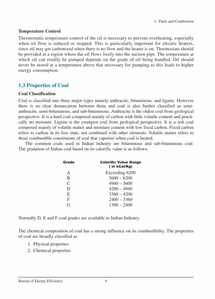
The common coals used in Indian industry are bituminous and sub-bituminous coal. The gradation of Indian coal based on its calorific value is as follows:
Grade Calorific Value Range
( in kCal/Kg)
A Exceeding 6200B 5600 – 6200C 4940 – 5600D 4200 – 4940E 3360 – 4200F 2400 – 3360G 1300 – 2400
Normally D, E and F coal grades are available to Indian Industry.
The chemical composition of coal has a strong influence on its combustibility. The propertiesof coal are broadly classified as
1. Physical properties
2. Chemical properties
1. Fuels and Combustion
6Bureau of Energy Efficiency
Ch-01.qxd 2/23/2005 11:18 AM Page 6

Physical Properties
Heating Value:
The heating value of coal varies from coal field to coal field. The typical GCVs for variouscoals are given in the Table 1.4.
Analysis of Coal
There are two methods: ultimate analysis and proximate analysis. The ultimate analysisdetermines all coal component elements, solid or gaseous and the proximate analysis deter-mines only the fixed carbon, volatile matter, moisture and ash percentages. The ultimateanalysis is determined in a properly equipped laboratory by a skilled chemist, while proxi-mate analysis can be determined with a simple apparatus. It may be noted that proximate hasno connection with the word “approximate”.
Measurement of Moisture
Determination of moisture is carried out by placing a sample of powdered raw coal of size 200-micron size in an uncovered crucible and it is placed in the oven kept at 108±2°C along withthe lid. Then the sample is cooled to room temperature and weighed again. The loss in weightrepresents moisture.
Measurement of Volatile Matter
Fresh sample of crushed coal is weighed, placed in a covered crucible, and heated in a furnaceat 900 ± 15°C. For the methodologies including that for carbon and ash, refer to IS 1350 partI:1984, part III, IV. The sample is cooled and weighed. Loss of weight represents moisture andvolatile matter. The remainder is coke (fixed carbon and ash).
Measurement of Carbon and Ash
The cover from the crucible used in the last test is removed and the crucible is heated over theBunsen burner until all the carbon is burned. The residue is weighed, which is the incombustibleash. The difference in weight from the previous weighing is the fixed carbon. In actual prac-tice Fixed Carbon or FC derived by subtracting from 100 the value of moisture, volatile matterand ash.
Proximate Analysis
Proximate analysis indicates the percentage by weight of the Fixed Carbon, Volatiles, Ash, andMoisture Content in coal. The amounts of fixed carbon and volatile combustible matter directly
1. Fuels and Combustion
7Bureau of Energy Efficiency
TABLE 1.4 GCV FOR VARIOUS COALS
Parameter Lignite Indian Coal Indonesian Coal South African Coal(Dry Basis)
GCV (kCal/kg) 4,500* 4,000 5,500 6,000
*GCV of lignite on ‘as received basis’ is 2500 – 3000
Ch-01.qxd 2/23/2005 11:18 AM Page 7
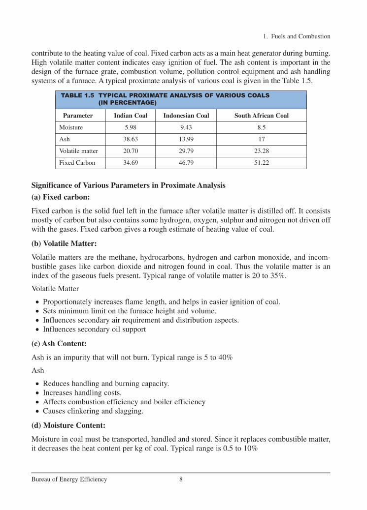
contribute to the heating value of coal. Fixed carbon acts as a main heat generator during burning.High volatile matter content indicates easy ignition of fuel. The ash content is important in thedesign of the furnace grate, combustion volume, pollution control equipment and ash handlingsystems of a furnace. A typical proximate analysis of various coal is given in the Table 1.5.
Significance of Various Parameters in Proximate Analysis
(a) Fixed carbon:
Fixed carbon is the solid fuel left in the furnace after volatile matter is distilled off. It consistsmostly of carbon but also contains some hydrogen, oxygen, sulphur and nitrogen not driven offwith the gases. Fixed carbon gives a rough estimate of heating value of coal.
(b) Volatile Matter:
Volatile matters are the methane, hydrocarbons, hydrogen and carbon monoxide, and incom-bustible gases like carbon dioxide and nitrogen found in coal. Thus the volatile matter is anindex of the gaseous fuels present. Typical range of volatile matter is 20 to 35%.
Volatile Matter
• Proportionately increases flame length, and helps in easier ignition of coal.• Sets minimum limit on the furnace height and volume.• Influences secondary air requirement and distribution aspects.• Influences secondary oil support
(c) Ash Content:
Ash is an impurity that will not burn. Typical range is 5 to 40%
Ash
• Reduces handling and burning capacity.• Increases handling costs.• Affects combustion efficiency and boiler efficiency• Causes clinkering and slagging.
(d) Moisture Content:
Moisture in coal must be transported, handled and stored. Since it replaces combustible matter,it decreases the heat content per kg of coal. Typical range is 0.5 to 10%
1. Fuels and Combustion
8Bureau of Energy Efficiency
Parameter Indian Coal Indonesian Coal South African Coal
Moisture 5.98 9.43 8.5
Ash 38.63 13.99 17
Volatile matter 20.70 29.79 23.28
Fixed Carbon 34.69 46.79 51.22
TABLE 1.5 TYPICAL PROXIMATE ANALYSIS OF VARIOUS COALS
(IN PERCENTAGE)
Ch-01.qxd 2/23/2005 11:18 AM Page 8

Moisture
• Increases heat loss, due to evaporation and superheating of vapour• Helps, to a limit, in binding fines.• Aids radiation heat transfer.
(e) Sulphur Content:
Typical range is 0.5 to 0.8% normally.
Sulphur
• Affects clinkering and slagging tendencies• Corrodes chimney and other equipment such as air heaters and economisers• Limits exit flue gas temperature.
Chemical Properties
Ultimate Analysis:
The ultimate analysis indicates the various elemental chemical constituents such as Carbon,Hydrogen, Oxygen, Sulphur, etc. It is useful in determining the quantity of air required for com-bustion and the volume and composition of the combustion gases. This information is requiredfor the calculation of flame temperature and the flue duct design etc. Typical ultimate analysesof various coals are given in the Table 1.6.
1. Fuels and Combustion
9Bureau of Energy Efficiency
TABLE 1.6 TYPICAL ULTIMATE ANALYSIS OF COALS
Parameter Indian Coal, % Indonesian Coal, %
Moisture 5.98 9.43
Mineral Matter (1.1 × Ash) 38.63 13.99
Carbon 41.11 58.96
Hydrogen 2.76 4.16
Nitrogen 1.22 1.02
Sulphur 0.41 0.56
Oxygen 9.89 11.88
TABLE 1.7 RELATIONSHIP BETWEEN ULTIMATE
ANALYSIS AND PROXIMATE ANALYSIS
%C = 0.97C+ 0.7(VM - 0.1A) – M(0.6–0.01M)
%H = 0.036C + 0.086 (VM–0.1xA) - 0.0035M2 (1–0.02M)
%N2 = 2.10 – 0.020 VM
where C = % of fixed carbon
A = % of ash
VM = % of volatile matter
M = % of moisture
Note: The above equation is valid for coal containing greater than 15% Moisture content.
Ch-01.qxd 2/23/2005 11:18 AM Page 9

Storage, Handling and Preparation of Coal
Uncertainty in the availability and transportation of fuel necessitates storage and subsequenthandling. Stocking of coal has its own disadvantages like build-up of inventory, space constraints, deterioration in quality and potential fire hazards. Other minor losses associatedwith the storage of coal include oxidation, wind and carpet loss. A 1% oxidation of coal has thesame effect as 1% ash in coal, wind losses may account for nearly 0.5 – 1.0% of the total loss.
The main goal of good coal storage is to minimise carpet loss and the loss due to sponta-neous combustion. Formation of a soft carpet, comprising of coal, dust, and soil causes carpetloss. On the other hand, gradual temperature builds up in a coal heap, on account of oxidationmay lead to spontaneous combustion of coal in storage.
The measures that would help in reducing the carpet losses are as follows:
1. Preparing a hard ground for coal to be stacked upon.
2. Preparing standard storage bays out of concrete and brick.
In process Industry, modes of coal handling range from manual to conveyor systems. It would be advisable to minimise the handling of coal so that further generation of fines andsegregation effects are reduced.
Preparation of Coal
Preparation of coal prior to feeding into the boiler is an important step for achieving good combustion. Large and irregular lumps of coal may cause the following problems:
1. Poor combustion conditions and inadequate furnace temperature.
2. Higher excess air resulting in higher stack loss.
3. Increase of unburnts in the ash.
4. Low thermal efficiency.
(a) Sizing of Coal
Proper coal sizing is one of the key measures to ensure efficient combustion. Proper coal sizing, with specific relevance to the type of firing system, helps towards even burning, reducedash losses and better combustion efficiency.
Coal is reduced in size by crushing and pulverizing. Pre-crushed coal can be economical forsmaller units, especially those which are stoker fired. In a coal handling system, crushing islimited to a top size of 6 or 4 mm. The devices most commonly used for crushing are the rotarybreaker, the roll crusher and the hammer mill.
It is necessary to screen the coal before crushing, so that only oversized coal is fed to the crusher.This helps to reduce power consumption in the crusher. Recommended practices in coal crushing are:
1. Incorporation of a screen to separate fines and small particles to avoid extra fine generationin crushing.
2. Incorporation of a magnetic separator to separate iron pieces in coal, which may damage thecrusher.
1. Fuels and Combustion
10Bureau of Energy Efficiency
Ch-01.qxd 2/23/2005 11:18 AM Page 10

The Table 1.8 gives the proper size of coal for various types of firing systems
(b) Conditioning of Coal
The fines in coal present problems in combustion on account of segregation effects.Segregation of fines from larger coal pieces can be reduced to a great extent by conditioningcoal with water. Water helps fine particles to stick to the bigger lumps due to surface tensionof the moisture, thus stopping fines from falling through grate bars or being carried away by thefurnace draft. While tempering the coal, care should be taken to ensure that moisture additionis uniform and preferably done in a moving or falling stream of coal.
If the percentage of fines in the coal is very high, wetting of coal can decrease the percentageof unburnt carbon and the excess air level required to be supplied for combustion. Table 1.9 shows the extent of wetting, depending on the percentage of fines in coal.
(c) Blending of Coal
In case of coal lots having excessive fines, it is advisable to blend the predominantly lumpedcoal with lots containing excessive fines. Coal blending may thus help to limit the extent offines in coal being fired to not more than 25%. Blending of different qualities of coal may alsohelp to supply a uniform coal feed to the boiler.
1. Fuels and Combustion
11Bureau of Energy Efficiency
TABLE 1.8 PROPER SIZE OF COAL FOR VARIOUS TYPES
OF FIRING SYSTEM
S. No. Types of Firing System Size (in mm)
1. Hand Firing(a) Natural draft 25–75(b) Forced draft 25–40
2. Stoker Firing(a) Chain grate
i) Natural draft 25–40ii) Forced draft 15–25
(b) Spreader Stoker 15–25
3. Pulverized Fuel Fired 75% below 75 micron*
4. Fluidized bed boiler < 10 mm
*1 Micron = 1/1000 mm
TABLE 1.9 EXTENT OF WETTING: FINES VS SURFACE
MOISTURE IN COAL
Fines (%) Surface Moisture (%)
10 – 15 4 – 5
15 – 20 5 – 6
20 – 25 6 – 7
25 – 30 7 – 8
Ch-01.qxd 2/23/2005 11:18 AM Page 11

The proximate and ultimate analysis of various coals are given in Table 1.10 and 1.11.
1. Fuels and Combustion
12Bureau of Energy Efficiency
TABLE 1.11 ULTIMATE ANALYSIS OF VARIOUS COALS
Bituminous Bituminous Indonesian CoalCoal (Sample I) Coal (Sample II)
Moisture (%) 5.98 4.39 9.43
Mineral matter (%) 38.63 47.86 13.99
Carbon (%) 42.11 36.22 58.96
Hydrogen (%) 2.76 2.64 4.16
Nitrogen (%) 1.22 1.09 1.02
Sulphur (%) 0.41 0.55 0.56
Oxygen (%) 9.89 7.25 11.88
GCV (kCal/kg) 4000 3500 5500
1.4 Properties of Gaseous Fuels
Gaseous fuels in common use are liquefied petroleum gases (LPG), Natural gas, producer gas,blast furnace gas, coke oven gas etc. The calorific value of gaseous fuel is expressed inKilocalories per normal cubic meter (kCal/Nm3) i.e. at normal temperature (20°C) and pressure(760 mm Hg).
Calorific Value
Since most gas combustion appliances cannot utlilize the heat content of the water vapour, grosscalorific value is of little interest. Fuel should be compared based on the net calorific value. Thisis especially true for natural gas, since increased hydrogen content results in high water forma-tion during combustion.
Lignite Bituminous Bituminous Coal Indonesian Coalcoal (Sample I) (Sample II)
Moisture (%) 50 5.98 4.39 9.43
Ash (%) 10.41* 38.65 47.86 13.99
Volatile matter (%) 47.76* 20.70 17.97 29.79
Fixed carbon (%) 41.83* 34.69 29.78 46.79
TABLE 1.10 PROXIMATE ANALYSIS OF TYPICAL COAL
*Dry Basis
Ch-01.qxd 2/23/2005 11:18 AM Page 12

Typical physical and chemical properties of various gaseous fuels are given in Table 1.12.
1. Fuels and Combustion
13Bureau of Energy Efficiency
TABLE 1.12 TYPICAL PHYSICAL AND CHEMICAL PROPERTIES OF
VARIOUS GASEOUS FUELS.
Fuel Gas Relative Higher Heating Air/Fuel ratio- Flame Temp. Flame Density Value kCal/Nm3 m3 of air to °C Speed m/s
m3 of Fuel
Natural Gas 0.6 9350 10 1954 0.290
Propane 1.52 22200 25 1967 0.460
Butane 1.96 28500 32 1973 0.870
LPG
LPG is a predominant mixture of propane and Butane with a small percentage of unsaturates(Propylene and Butylene) and some lighter C2 as well as heavier C5 fractions. Included in the LPGrange are propane (C3H8), Propylene(C3H6), normal and iso-butane (C4H10) and Butylene(C4H8).
LPG may be defined as those hydrocarbons, which are gaseous at normal atmospheric pressure, but may be condensed to the liquid state at normal temperature, by the application ofmoderate pressures. Although they are normally used as gases, they are stored and transportedas liquids under pressure for convenience and ease of handling. Liquid LPG evaporates to produce about 250 times volume of gas.
LPG vapour is denser than air: butane is about twice as heavy as air and propane about oneand a half times as heavy as air. Consequently, the vapour may flow along the ground and intodrains sinking to the lowest level of the surroundings and be ignited at a considerable distancefrom the source of leakage. In still air vapour will disperse slowly. Escape of even small quan-tities of the liquefied gas can give rise to large volumes of vapour / air mixture and thus causeconsiderable hazard. To aid in the detection of atmospheric leaks, all LPG’s are required to beodorized. There should be adequate ground level ventilation where LPG is stored. For this veryreason LPG cylinders should not be stored in cellars or basements, which have no ventilationat ground level.
Natural Gas
Methane is the main constituent of Natural gas and accounting for about 95% of the total vol-ume. Other components are: Ethane, Propane, Butane, Pentane, Nitrogen, Carbon Dioxide, andtraces of other gases. Very small amounts of sulphur compounds are also present. Sincemethane is the largest component of natural gas, generally properties of methane are used whencomparing the properties of natural gas to other fuels.
Natural gas is a high calorific value fuel requiring no storage facilities. It mixes with airreadily and does not produce smoke or soot. It has no sulphur content. It is lighter than air anddisperses into air easily in case of leak. A typical comparison of carbon contents in oil, coal andgas is given in the table 1.13.
Ch-01.qxd 2/23/2005 11:18 AM Page 13

1.5 Properties of Agro Residues
The use of locally available agro residues is on the rise. This includes rice husk, coconut shells,groundnut shells, Coffee husk, Wheat stalk etc. The properties of a few of them are given in thetable 1.14 and 1.15.
1. Fuels and Combustion
14Bureau of Energy Efficiency
TABLE 1.14 PROXIMATE ANALYSIS OF TYPICAL AGRO RESIDUES
Deoiled Bran Paddy Husk Saw Dust Coconut Shell
Moisture 7.11 10.79 37.98 13.95
Ash 18.46 16.73 1.63 3.52
Volatile Matter 59.81 56.46 81.22 61.91
Fixed Carbon 14.62 16.02 17.15 20.62
TABLE 1.15 ULTIMATE ANALYSIS OF TYPICAL AGRO RESIDUES
Deoiled Bran Paddy Husk Saw Dust Coconut Shell
Moisture 7.11 10.79 37.98 13.95
Mineral Matter 19.77 16.73 1.63 3.52
Carbon 36.59 33.95 48.55 44.95
Hydrogen 4.15 5.01 6.99 4.99
Nitrogen 0.82 0.91 0.80 0.56
Sulphur 0.54 0.09 0.10 0.08
Oxygen 31.02 32.52 41.93 31.94
GCV (kCal/kg) 3151 3568 4801 4565
Fuel Oil Coal Natural Gas
Carbon 84 41.11 74
Hydrogen 12 2.76 25
Sulphur 3 0.41 -
Oxygen 1 9.89 Trace
Nitrogen Trace 1.22 0.75
Ash Trace 38.63 -
Water Trace 5.98 -
TABLE 1.13 COMPARISON OF CHEMICAL
COMPOSITION OF VARIOUS FUELS
Ch-01.qxd 2/23/2005 11:18 AM Page 14

1.6 Combustion
Principle of Combustion
Combustion refers to the rapid oxidation of fuel accompanied by the production of heat, or heatand light. Complete combustion of a fuel is possible only in the presence of an adequate supply of oxygen.
Oxygen (O2) is one of the most common elements on earth making up 20.9% of our air.Rapid fuel oxidation results in large amounts of heat. Solid or liquid fuels must be changed toa gas before they will burn. Usually heat is required to change liquids or solids into gases. Fuelgases will burn in their normal state if enough air is present.
Most of the 79% of air (that is not oxygen) is nitrogen, with traces of other elements.Nitrogen is considered to be a temperature reducing dilutant that must be present to obtain theoxygen required for combustion.
Nitrogen reduces combustion efficiency by absorbing heat from the combustion of fuels anddiluting the flue gases. This reduces the heat available for transfer through the heat exchangesurfaces. It also increases the volume of combustion by-products, which then have to travelthrough the heat exchanger and up the stack faster to allow the introduction of additional fuelair mixture.
This nitrogen also can combine with oxygen (particularly at high flame temperatures) toproduce oxides of nitrogen (NOx), which are toxic pollutants.
Carbon, hydrogen and sulphur in the fuel combine with oxygen in the air to form carbondioxide, water vapour and sulphur dioxide, releasing 8084 kCals, 28922 kCals & 2224 kCals ofheat respectively. Under certain conditions, Carbon may also combine with Oxygen to formCarbon Monoxide, which results in the release of a smaller quantity of heat (2430 kCals/kg ofcarbon) Carbon burned to CO2 will produce more heat per pound of fuel than when CO orsmoke are produced.
1. Fuels and Combustion
15Bureau of Energy Efficiency
C + O2 → CO2 + 8084 kCals/kg of Carbon2C + O2 → 2 CO + 2430 kCals/kg of Carbon2H2 + O2 → 2H2O + 28,922 kCals/kg of HydrogenS + O2 → SO2 + 2,224 kCals/kg of Sulphur
Each kilogram of CO formed means a loss of 5654 kCal of heat.(8084-2430).
3 T’s of Combustion
The objective of good combustion is to release all of the heat in the fuel. This is accomplishedby controlling the “three T’s” of combustion which are (1) Temperature high enough to igniteand maintain ignition of the fuel, (2) Turbulence or intimate mixing of the fuel and oxygen, and(3) Time sufficient for complete combustion.
Commonly used fuels like natural gas and propane generally consist of carbon and hydrogen.Water vapor is a by-product of burning hydrogen. This robs heat from the flue gases, whichwould otherwise be available for more heat transfer.
Natural gas contains more hydrogen and less carbon per kg than fuel oils and as such produces more water vapor. Consequently, more heat will be carried away by exhaust while firing natural gas.
Ch-01.qxd 2/23/2005 11:18 AM Page 15

Too much, or too little fuel with the available combustion air may potentially result inunburned fuel and carbon monoxide generation. A very specific amount of O2 is needed for perfect combustion and some additional (excess) air is required for ensuring complete combus-tion. However, too much excess air will result in heat and efficiency losses.
1. Fuels and Combustion
16Bureau of Energy Efficiency
Not all of the heat in the fuel are converted to heat and absorbed by the steam generation equip-ment. Usually all of the hydrogen in the fuel is burned and most boiler fuels, allowable withtoday’s air pollution standards, contain little or no sulfur. So the main challenge in combustionefficiency is directed toward unburned carbon (in the ash or incompletely burned gas), whichforms CO instead of CO2.
1.7 Combustion of Oil
Heating Oil to Correct Viscosity
When atomizing oil, it is necessary to heat it enough to get the desired viscosity. This temper-ature varies slightly for each grade of oil. The lighter oils do not usually require pre-heating.Typical viscosity at the burner tip ( for LAP, MAP & HAP burners) for furnace oil should be100 Redwood seconds-1 which would require heating the oil to about 105°C.
Stoichiometric Combustion
The efficiency of a boiler or furnace depends on efficiency of thecombustion system. The amount of air required for completecombustion of the fuel depends on the elemental constituents ofthe fuel that is Carbon, Hydrogen, and Sulphur etc. This amountof air is called stoichiometric air. For ideal combustion processfor burning one kg of a typical fuel oil containing 86% Carbon,12% Hydrogen, 2% Sulphur, theoretically required quantity of airis 14.1 kg. This is the minimum air that would be required if mix-ing of fuel and air by the burner and combustion is perfect. Thecombustion products are primarily Carbon Dioxide (CO2), watervapor (H2O) and Sulphur Dioxide (SO2), which pass through thechimney along with the Nitrogen (N2) in the air,.
After surrendering useful heat in the heat absorption area of a furnace or boiler, the combustion products or fuel gases leave the system through the chimney, carrying away a significant quantity of heat with them.
Rules for combustion of oil
1. Atomize the oil completelyto produce a fine uniformspray
2. Mix the air and fuel thoroughly
3. Introduce enough air forcombustion, but limit theexcess air to a maximum of15%
4. Keep the burners in goodcondition
Ch-01.qxd 2/23/2005 11:18 AM Page 16
1. Fuels and Combustion
17Bureau of Energy Efficiency
Constituents % By weightCarbon 85.9
Hydrogen 12
Oxygen 0.7
Nitrogen 0.5
Sulphur 0.5
H2O` 0.35
Ash 0.05
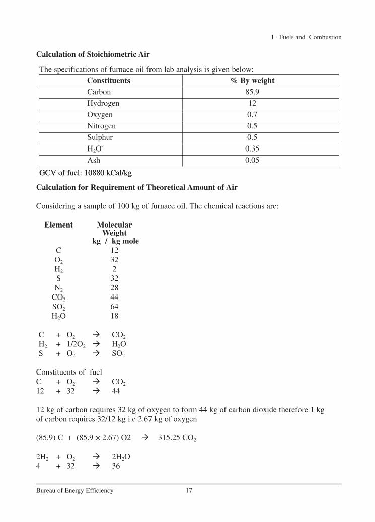
GCV of fuel: 10880 kCal/kgGCV of fuel: 10880 kCal/kg
The specifications of furnace oil from lab analysis is given below:
Calculation of Stoichiometric Air
Calculation for Requirement of Theoretical Amount of Air
Considering a sample of 100 kg of furnace oil. The chemical reactions are:
Element MolecularWeight
kg / kg moleC 12O2 32H2 2S 32N2 28
CO2 44SO2 64H2O 18
C + O2 � CO2
H2 + 1/2O2 � H2OS + O2 � SO2
Constituents of fuelC + O2 � CO2
12 + 32 � 44
12 kg of carbon requires 32 kg of oxygen to form 44 kg of carbon dioxide therefore 1 kg of carbon requires 32/12 kg i.e 2.67 kg of oxygen
(85.9) C + (85.9 × 2.67) O2 � 315.25 CO2
2H2 + O2 � 2H2O4 + 32 � 36
Ch-01.qxd 2/23/2005 11:18 AM Page 17
1. Fuels and Combustion
18Bureau of Energy Efficiency
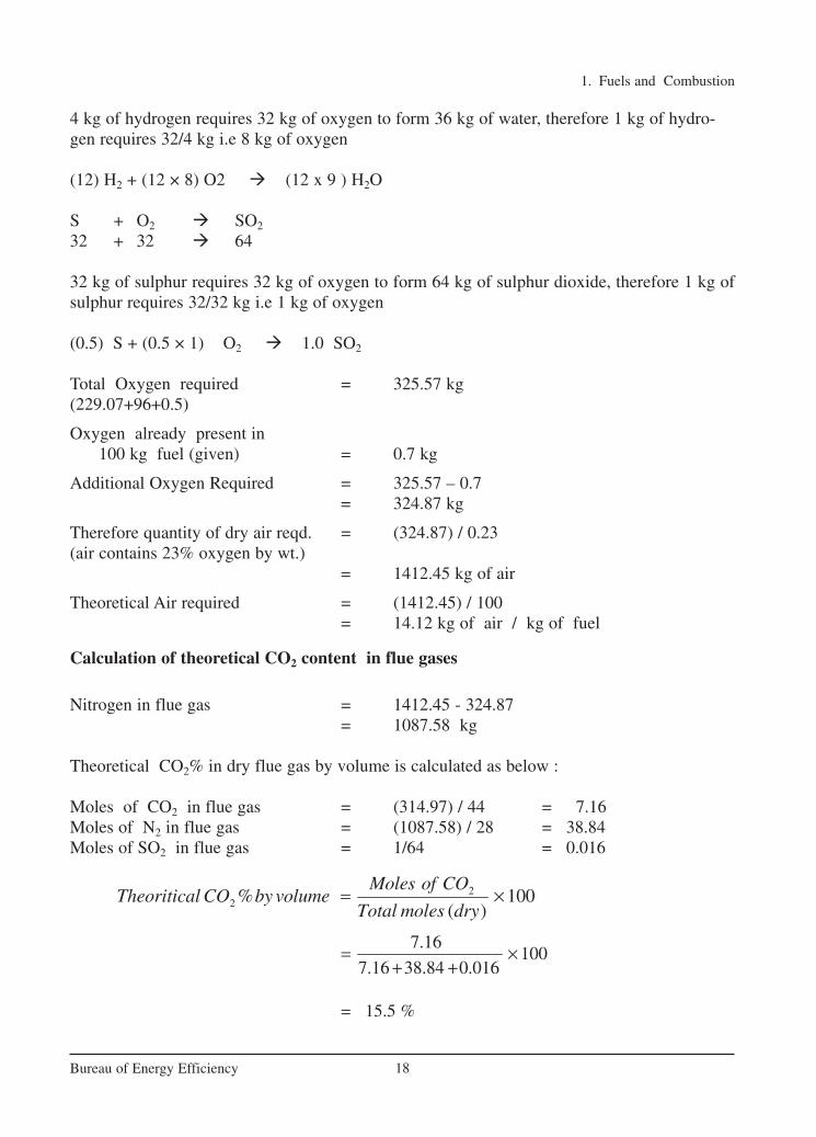
4 kg of hydrogen requires 32 kg of oxygen to form 36 kg of water, therefore 1 kg of hydro-gen requires 32/4 kg i.e 8 kg of oxygen
(12) H2 + (12 × 8) O2 � (12 x 9 ) H2O
S + O2 � SO2
32 + 32 � 64
32 kg of sulphur requires 32 kg of oxygen to form 64 kg of sulphur dioxide, therefore 1 kg ofsulphur requires 32/32 kg i.e 1 kg of oxygen
(0.5) S + (0.5 × 1) O2 � 1.0 SO2
Total Oxygen required = 325.57 kg(229.07+96+0.5)
Oxygen already present in 100 kg fuel (given) = 0.7 kg
Additional Oxygen Required = 325.57 – 0.7= 324.87 kg
Therefore quantity of dry air reqd. = (324.87) / 0.23(air contains 23% oxygen by wt.)
= 1412.45 kg of air
Theoretical Air required = (1412.45) / 100= 14.12 kg of air / kg of fuel
Calculation of theoretical CO2 content in flue gases
Nitrogen in flue gas = 1412.45 - 324.87= 1087.58 kg
Theoretical CO2% in dry flue gas by volume is calculated as below :
Moles of CO2 in flue gas = (314.97) / 44 = 7.16Moles of N2 in flue gas = (1087.58) / 28 = 38.84Moles of SO2 in flue gas = 1/64 = 0.016
= 15.5 %
22 % 100
( )
Moles of COTheoritical CO by volume
Total moles dry= ×
7.16100
7.16 38.84 0.016= ×
+ +
Ch-01.qxd 2/23/2005 11:18 AM Page 18

1. Fuels and Combustion
19Bureau of Energy Efficiency
Calculation of constituents of flue gas with excess air
% CO2 measured in flue gas = 10% (measured)
= 55%
Theoretical air required for 100 kg of fuel burnt = 1412.45 kgTotal quantity. of air supply required with 55% excess air = 1412.45 X 1.55
= 2189.30 kgExcess air quantity = 2189.30 – 1412.45
= 776.85 kg.
O2 = 776.85 X 0.23= 178.68
N2 = 776.85 – 178.68= 598.17 kg
The final constitution of flue gas with 55% excess air for every 100 kg fuel.
CO2 = 314.97 kgH2O = 108.00 kgSO2 = 1 kgO2 = 178.68 kgN2 = 1087.58 + 598.17
= 1685.75 kg
Calculation of Theoretical CO2% in Dry Flue Gas By Volume
Moles of CO2 in flue gas = 314.97/44 = 7.16
Moles of SO2 in flue gas = 1/64 = 0.016
Moles of O2 in flue gas = 178.68 / 32 = 5.58
Moles of N2 in flue gas = 1685.75 / 28 = 60.20
2
2
%% 1 100
%
Theoritical COExcess air
Actual CO
= − ×
22 % 100
( )
Moles of COTheoritical CO by volume
Total moles dry= ×
15.5% 1 100
10Excess air
= − ×
7.16100
7.16 0.016 5.58 60.20= ×
+ + +
Ch-01.qxd 2/23/2005 11:18 AM Page 19

= 10%
Theoretical O2% by volume
1. Fuels and Combustion
Optimizing Excess Air and Combustion
For complete combustion of every one kg of fuel oil 14.1 kg of air is needed. In practice, mixing is never perfect, a certain amount of excess air is needed to complete combustion andensure that release of the entire heat contained in fuel oil. If too much air than what is requiredfor completing combustion were allowed to enter, additional heat would be lost in heating thesurplus air to the chimney temperature. This would result in increased stack losses. Less airwould lead to the incomplete combustion and smoke. Hence, there is an optimum excess airlevel for each type of fuel.
Control of Air and Analysis of Flue Gas
Thus in actual practice, the amount of combustion air required will be much higher than optimally needed. Therefore some of the air gets heated in the furnace boiler and leaves throughthe stack without participating in the combustion
Chemical analysis of the gases is an objective method that helps in achieving finer air control.By measuring carbon dioxide (CO2) or oxygen (O2) in flue gases by continuous recordinginstruments or Orsat apparatus or portable fyrite, the excess air level as well as stack losses canbe estimated with the graph as shown in Figure 1.2 and Figure 1.3. The excess air to be supplied depends on the type of fuel and the firing system. For optimum combustion of fuel oil,the CO2 or O2 in flue gases should be maintained at 14 -15% in case of CO2 and 2-3% in caseof O2.
20Bureau of Energy Efficiency
Figure 1.2 Relation Between CO2 and Excess Air for Fuel Oil
7.16100
72.956= ×
5.58 100100 7.5%
72.956
x= × =
Ch-01.qxd 2/23/2005 11:18 AM Page 20

1. Fuels and Combustion
21Bureau of Energy Efficiency
Oil Firing Burners
The burner is the principal device for the firing of fuel. The primary function of burner is toatomise fuel to millions of small droplets so that the surface area of the fuel is increasedenabling intimate contact with oxygen in air. The finer the fuel droplets are atomised, morereadily will the particles come in contact with the oxygen in the air and burn.
Normally, atomisation is carried out by primary air and completion of combustion isensured by secondary air. Burners for fuel oil can be classified on the basis of the technique toprepare the fuel for burning i.e. atomisation.
Figure 1.4 shows a simplified burner head. The air is brought into the head by means of aforced draft blower or fan. The fuel is metered into the head through a series of valves. In orderto get proper combustion, the air molecules must be thoroughly mixed with the fuel moleculesbefore they actually burn. The air in the center is the primary air used for atomization and theone surrounding is the secondary air which ensures complete combustion.
The mixing is achieved by burner parts designed to create high turbulence. If insufficient tur-bulence is produced by the burner, the combustion will be incomplete and samples taken at thestack will reveal carbon monoxide as evidence.
Since the velocity of air affects the turbulence, it becomes harder and harder to get good fueland air mixing at higher turndown ratios since the air amount is reduced. Towards the highestturndown ratios of any burner, it becomes necessary to increase the excess air amounts to obtain
Figure 1.3: Relation Between Residual Oxygen and Excess Air
Figure 1.4 Burner Head
FUEL
AIR
AIR
AIR
Ch-01.qxd 2/23/2005 11:18 AM Page 21
1. Fuels and Combustion
22Bureau of Energy Efficiency
enough turbulence to get proper mixing. The better burner design will be one that is able toproperly mix the air and fuel at the lowest possible air flow or excess air.
An important aspect to be considered in selection of burner is turndown ratio. Turndownratio is the relationship between the maximum and minimum fuel input without affecting theexcess air level. For example, a burner whose maximum input is 250,000 kCals and minimumrate is 50,000 kCals, has a ‘Turn-Down Ratio’ of 5 to 1.
1.8 Combustion of Coal
Features of coal combustion
1 kg of coal will typically require 7–8 kg of airdepending upon the carbon, hydrogen, nitrogen,oxygen and sulphur content for complete combus-tion. This air is also known as theoretical or stoi-chiometric air.
If for any reason the air supplied is inadequate,the combustion will be incomplete. The result ispoor generation of heat with some portions of car-bon remaining unburnt (black smoke) and formingcarbon monoxide instead of carbon dioxides.
As in the case of oil, coal cannot be burnt withstoichiometric quantity of air. Complete combustion is not achieved unless an excess of air issupplied.
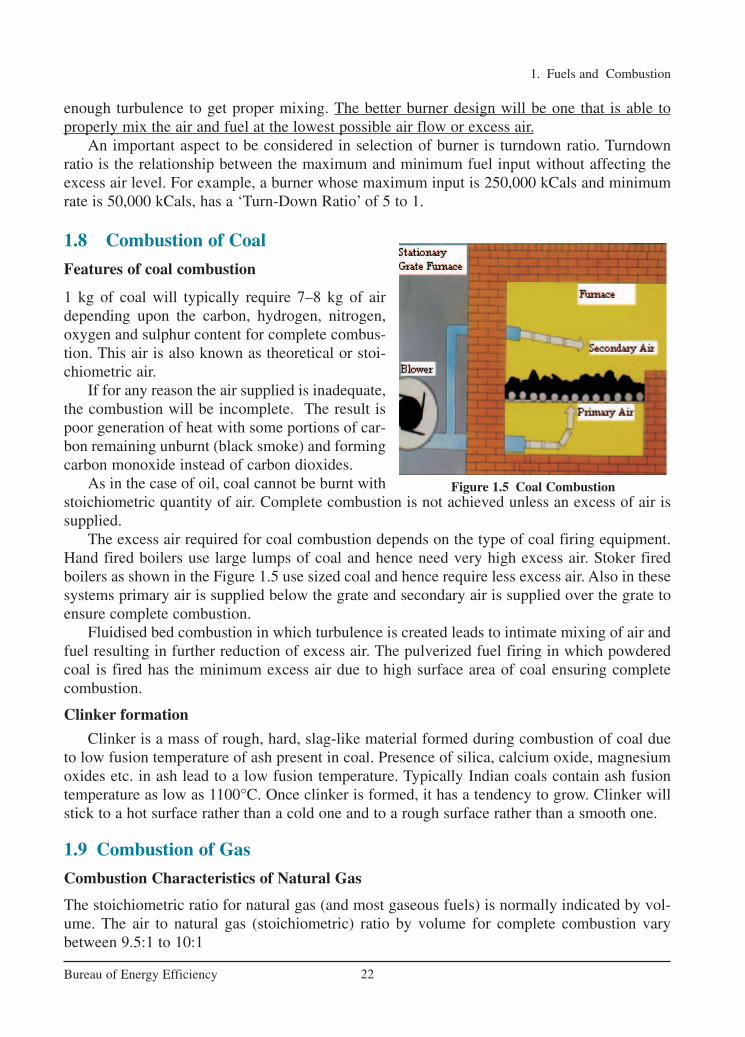
The excess air required for coal combustion depends on the type of coal firing equipment.Hand fired boilers use large lumps of coal and hence need very high excess air. Stoker firedboilers as shown in the Figure 1.5 use sized coal and hence require less excess air. Also in thesesystems primary air is supplied below the grate and secondary air is supplied over the grate toensure complete combustion.
Fluidised bed combustion in which turbulence is created leads to intimate mixing of air andfuel resulting in further reduction of excess air. The pulverized fuel firing in which powderedcoal is fired has the minimum excess air due to high surface area of coal ensuring completecombustion.
Clinker formation
Clinker is a mass of rough, hard, slag-like material formed during combustion of coal dueto low fusion temperature of ash present in coal. Presence of silica, calcium oxide, magnesiumoxides etc. in ash lead to a low fusion temperature. Typically Indian coals contain ash fusiontemperature as low as 1100°C. Once clinker is formed, it has a tendency to grow. Clinker willstick to a hot surface rather than a cold one and to a rough surface rather than a smooth one.
1.9 Combustion of Gas
Combustion Characteristics of Natural Gas
The stoichiometric ratio for natural gas (and most gaseous fuels) is normally indicated by vol-ume. The air to natural gas (stoichiometric) ratio by volume for complete combustion varybetween 9.5:1 to 10:1
Figure 1.5 Coal Combustion
Ch-01.qxd 2/23/2005 11:18 AM Page 22
1. Fuels and Combustion
23Bureau of Energy Efficiency
Natural gas is essentially pure methane, CH4. Its combustion can be represented as follows:
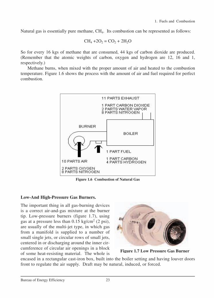
CH4 +2O2 = CO2 + 2H2O
So for every 16 kgs of methane that are consumed, 44 kgs of carbon dioxide are produced.(Remember that the atomic weights of carbon, oxygen and hydrogen are 12, 16 and 1, respectively.)
Methane burns, when mixed with the proper amount of air and heated to the combustiontemperature. Figure 1.6 shows the process with the amount of air and fuel required for perfectcombustion.
Figure 1.6 Combustion of Natural Gas
Low-And High-Pressure Gas Burners.
The important thing in all gas-burning devicesis a correct air-and-gas mixture at the burnertip. Low-pressure burners (figure 1.7), usinggas at a pressure less than 0.15 kg/cm2 (2 psi),are usually of the multi-jet type, in which gasfrom a manifold is supplied to a number ofsmall single jets, or circular rows of small jets,centered in or discharging around the inner cir-cumference of circular air openings in a blockof some heat-resisting material. The whole isencased in a rectangular cast-iron box, built into the boiler setting and having louver doorsfront to regulate the air supply. Draft may be natural, induced, or forced.
Figure 1.7 Low Pressure Gas Burner
Ch-01.qxd 2/23/2005 11:18 AM Page 23

1. Fuels and Combustion
24Bureau of Energy Efficiency
In a high-pressure gas mixer (figure 1.8),the energy of the gas jet draws air into themixing chamber and delivers a correctly proportioned mixture to the burner. When theregulating valve is opened, gas flows througha small nozzle into a venturi tube (a tube witha contracted section). Entrainment of air withhigh-velocity gas in the narrow venturi section draws air in through large openings inthe end. The gas-air mixture is piped to aburner. The gas-burner tip may be in a variety of forms. In a sealed-in tip type, theproper gas-air mixture is piped to the burner,and no additional air is drawn in around the burner tip. Size of the air openings in the venturitube end is increased or decreased by turning a revolving shutter, which can be locked in anydesired position. Excess air levels in natural gas burner is in the order of 5%.
1.10 Draft System
The function of draft in a combustion system is to exhaust the products of combustion into theatmosphere. The draft can be classified into two types namely Natural and Mechanical Draft.
Natural Draft
It is the draft produced by a chimney alone. It is caused by the difference in weight between thecolumn of hot gas inside the chimney and column of outside air of the same height and crosssection. Being much lighter than outside air, chimney flue gas tends to rise, and the heavier out-side air flows in through the ash pit to take its place. It is usually controlled by hand-operateddampers in the chimney and breeching connecting the boiler to the chimney. Here no fans orblowers are used. The products of combustion are discharged at such a height that it will not bea nuisance to the surrounding community.
Mechanical Draft
It is draft artificially produced by fans. Three basic types of drafts that are applied are :
Balanced Draft: Forced-draft (F-D) fan (blower) pushes air into the furnace and an induced-draft (I-D) fan draws gases into the chimney thereby providing draft to remove the gases fromthe boiler. Here the pressure is maintained between 0.05 to 0.10 in. of water gauge below atmos-pheric pressure in the case of boilers and slightly positive for reheating and heat treatment fur-naces.
Induced Draft: An induced-draft fan draws enough draft for flow into the furnace, causing theproducts of combustion to discharge to atmosphere. Here the furnace is kept at a slight nega-tive pressure below the atmospheric pressure so that combustion air flows through the system.
Forced Draft: The Forced draft system uses a fan to deliver the air to the furnace, forcing com-bustion products to flow through the unit and up the stack.
Figure 1.8 High Pressure Gas Mixer
Ch-01.qxd 2/23/2005 11:18 AM Page 24
1. Fuels and Combustion
25Bureau of Energy Efficiency
1.11 Combustion Controls
Combustion controls assist the burner in regulation of fuel supply, air supply, (fuel to air ratio),and removal of gases of combustion to achieve optimum boiler efficiency. The amount of fuelsupplied to the burner must be in proportion to the steam pressure and the quantity of steamrequired. The combustion controls are also necessary as safety device to ensure that the boileroperates safely.
Various types of combustion controls in use are:
On/Off Control
The simplest control, ON/OFF control means that either the burner is firing at full rate or it isOFF. This type of control is limited to small boilers.
High/Low/Off Control
Slightly more complex is HIGH/LOW/OFF system where the burner has two firing rates. The burner operates at slower firing rate and then switches to full firing as needed. Burner canalso revert to low firing position at reduced load. This control is fitted to medium sized boilers.
Modulating Control
The modulating control operates on the principle of matching the steam pressure demand byaltering the firing rate over the entire operating range of the boiler. Modulating motors use conventional mechanical linkage or electric valves to regulate the primary air, secondary air,and fuel supplied to the burner. Full modulation means that boiler keeps firing, and fuel and airare carefully matched over the whole firing range to maximize thermal efficiency.
Ch-01.qxd 2/23/2005 11:18 AM Page 25

1. Fuels and Combustion
26Bureau of Energy Efficiency
REFERENCES 1. Combustion Engineering and Fuel Technology, Oxford & IBH Publishing Company
A.K.Shaha
W.W.W. pcra.org.
1) Name two liquid fuels, solid fuels and gaseous fuels used in boilers.
2) Which parameter influences the Viscosity of liquid fuel?
3) Which element in fuel oil influences corrosion?
4) What is the significance of pre-heating furnace oil before burning?
5) What are the effects of contaminants in liquid fuels?
6) Explain the difference between gross calorific value and net calorific value.
7) What is the difference between proximate analysis and ultimate analysis of coal?
8) What are the uses of proximate and ultimate analysis?
9) Explain why natural gas requires least amount of excess air?
10) What is the effect of fines on coal combustion and how to overcome them?
11) What are the major constituent of LPG and Natural gas?
12) Why excess air is required for complete combustion?
13) What is the typical stoichiometric air fuel ratio for furnace oil?
14) The measured CO2 is 8% in an oil fired boiler flue gas. Theoretical CO2 content forthe fuel fired is 16%. Estimate the % excess air level?
QUESTIONS
Ch-01.qxd 2/23/2005 11:18 AM Page 26

2. BOILERS
27Bureau of Energy Efficiency
SyllabusBoilers: Types, Combustion in boilers, Performances evaluation, Analysis of losses, Feedwater treatment, Blow down, Energy conservation opportunities.
2.1 Introduction
A boiler is an enclosed vessel that provides a means for combustion heat to be transferred intowater until it becomes heated water or steam. The hot water or steam under pressure is thenusable for transferring the heat to a process. Water is a useful and cheap medium fortransferring heat to a process. When water is boiled into steam its volume increases about 1,600times, producing a force that is almost as explosive as gunpowder. This causes the boiler to beextremely dangerous equipment that must be treated with utmost care.
The process of heating a liquid until it reaches its gaseous state is called evaporation. Heatis transferred from one body to another by means of (1) radiation, which is the transfer of heatfrom a hot body to a cold body without a conveying medium, (2) convection, the transfer ofheat by a conveying medium, such as air or water and (3) conduction, transfer of heat by actualphysical contact, molecule to molecule.
Boiler Specification
The heating surface is anypart of the boiler metalthat has hot gases of com-bustion on one side andwater on the other. Anypart of the boiler metalthat actually contributesto making steam is heat-ing surface. The amountof heating surface of aboiler is expressed in square meters. The larger the heating surface a boiler has, the moreefficient it becomes. The quantity of the steam produced is indicated in tons of water evap-orated to steam per hour. Maximum continuous rating is the hourly evaporation that can bemaintained for 24 hours. F & A means the amount of steam generated from water at 100 °Cto saturated steam at 100 °C.
Indian Boiler RegulationThe Indian Boilers Act was enacted to consolidate and amend the law relating to steam boilers.Indian Boilers Regulation (IBR) was created in exercise of the powers conferred by section 28& 29 of the Indian Boilers Act.
Typical Boiler Specification
Boiler Make & Year : XYZ & 2003
MCR(Maximum Continuous Rating) : 10TPH (F & A 100°C)
Rated Working Pressure : 10.54 kg/cm2(g)
Type of Boiler : 3 Pass Fire tube
Fuel Fired : Fuel Oil
Ch-02.qxd 2/23/2005 11:21 AM Page 27

IBR Steam Boilers means any closed vessel exceeding 22.75 liters in capacity and which isused expressively for generating steam under pressure and includes any mounting or otherfitting attached to such vessel, which is wholly, or partly under pressure when the steam is shutoff.
IBR Steam Pipe means any pipe through which steam passes from a boiler to a prime moveror other user or both, if pressure at which steam passes through such pipes exceeds 3.5 kg/cm2
above atmospheric pressure or such pipe exceeds 254 mm in internal diameter and includes ineither case any connected fitting of a steam pipe.
2.2 Boiler Systems
The boiler system comprises of: feed water system, steam system and fuel system. The feedwater system provides water to the boiler and regulates it automatically to meet the steamdemand. Various valves provide access for maintenance and repair. The steam system collectsand controls the steam produced in the boiler. Steam is directed through a piping system to thepoint of use. Throughout the system, steam pressure is regulated using valves and checked withsteam pressure gauges. The fuel system includes all equipment used to provide fuel to gener-ate the necessary heat. The equipment required in the fuel system depends on the type of fuelused in the system. A typical boiler room schematic is shown in Figure 2.1.
2. Boilers
28Bureau of Energy Efficiency
Figure 2.1 Boiler Room Schematic
The water supplied to the boiler that is converted into steam is called feed water. The twosources of feed water are: (1) Condensate or condensed steam returned from the processes and(2) Makeup water (treated raw water) which must come from outside the boiler room and plantprocesses. For higher boiler efficiencies, the feed water is preheated by economizer, using thewaste heat in the flue gas.
Ch-02.qxd 2/23/2005 11:21 AM Page 28

2. Boilers
29Bureau of Energy Efficiency
2.3 Boiler Types and Classifications
There are virtually infinite numbers of boiler designs but generally they fit into one of two cat-egories:
Fire tube or “fire in tube” boilers;contain long steel tubes throughwhich the hot gasses from afurnace pass and around which thewater to be converted to steam cir-culates. (Refer Figure 2.2). Firetube boilers, typically have a lowerinitial cost, are more fuel efficientand easier to operate, but they arelimited generally to capacities of25 tons/hr and pressures of 17.5 kg/cm2.
Water tube or “water in tube” boilers in whichthe conditions are reversed with the water passingthrough the tubes and the hot gasses passing outsidethe tubes (see figure 2.3). These boilers can be ofsingle- or multiple-drum type. These boilers can bebuilt to any steam capacities and pressures, and havehigher efficiencies than fire tube boilers.
Packaged Boiler: The packaged boiler is socalled because it comes as a complete package.Once delivered to site, it requires only the steam,water pipe work, fuel supply and electricalconnections to be made for it to becomeoperational. Package boilers are generally ofshell type with fire tube design so as to achievehigh heat transfer rates by both radiation andconvection (Refer Figure 2.4).
Figure 2.2 Fire Tube Boiler
Figure 2.3 Water Tube Boiler
Figure 2.4 Packaged Boiler
Ch-02.qxd 2/23/2005 11:21 AM Page 29

The features of package boilers are:
� Small combustion space and high heat release rate resulting in faster evaporation.� Large number of small diameter tubes leading to good convective heat transfer.� Forced or induced draft systems resulting in good combustion efficiency.� Number of passes resulting in better overall heat transfer.� Higher thermal efficiency levels compared with other boilers.
These boilers are classified based on the number of passes – the number of times the hotcombustion gases pass through the boiler. The combustion chamber is taken, as the first passafter which there may be one, two or three sets of fire-tubes. The most common boiler of thisclass is a three-pass unit with two sets of fire-tubes and with the exhaust gases exiting throughthe rear of the boiler.
Stoker Fired Boiler:
Stokers are classified according to the method of feeding fuel to the furnace and by the type ofgrate. The main classifications are:
1. Chain-grate or traveling-grate stoker
2. Spreader stoker
Chain-Grate or Traveling-Grate Stoker Boiler
Coal is fed onto one end of a moving steel chain grate. As grate moves along the length of thefurnace, the coal burns before dropping off at the end as ash. Some degree of skill is required,particularly when setting up the grate, air dampers and baffles, to ensure clean combustion leaving minimum of unburnt carbon in the ash.
2. Boilers
30Bureau of Energy Efficiency
Figure 2.5 Chain Grate Stoker
Ch-02.qxd 2/23/2005 11:21 AM Page 30

2. Boilers
31Bureau of Energy Efficiency
The coal-feed hopper runs along the entire coal-feed end of the furnace. A coal grate is usedto control the rate at which coal is fed into the furnace, and to control the thickness of the coalbed and speed of the grate. Coal must be uniform in size, as large lumps will not burn out com-pletely by the time they reach the end of the grate. As the bed thickness decreases from coal-feed end to rear end, different amounts of air are required- more quantity at coal-feed end andless at rear end (see Figure 2.5).
Spreader Stoker Boiler
Spreader stokers (see figure 2.6) utilize a combination of suspension burning and grate burning.The coal is continually fed into the furnace above a burning bed of coal. The coal fines areburned in suspension; the larger particles fall to the grate, where they are burned in a thin, fast-burning coal bed. This method of firing provides good flexibility to meet load fluctuations,since ignition is almost instantaneous when firing rate is increased. Hence, the spreader stokeris favored over other types of stokers in many industrial applications.
Figure 2.6 Spreader Stoker
Pulverized Fuel Boiler
Most coal-fired power station boilers use pulverized coal, and many of the larger industrialwater-tube boilers also use this pulverized fuel. This technology is well developed, and thereare thousands of units around the world, accounting for well over 90% of coal-fired capacity.
The coal is ground (pulverised) to a fine powder, so that less than 2% is +300 micro metre(µm) and 70-75% is below 75 microns, for a bituminous coal. It should be noted that too finea powder is wasteful of grinding mill power. On the other hand, too coarse a powder does notburn completely in the combustion chamber and results in higher unburnt losses.
The pulverised coal is blown with part of the combustion air into the boiler plant through aseries of burner nozzles. Secondary and tertiary air may also be added. Combustion takes place
Ch-02.qxd 2/23/2005 11:21 AM Page 31
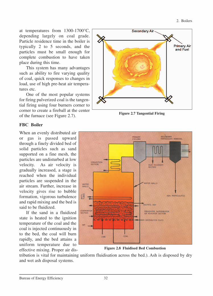
at temperatures from 1300-1700°C,depending largely on coal grade.Particle residence time in the boiler istypically 2 to 5 seconds, and the particles must be small enough forcomplete combustion to have takenplace during this time.
This system has many advantagessuch as ability to fire varying qualityof coal, quick responses to changes inload, use of high pre-heat air tempera-tures etc.
One of the most popular systemsfor firing pulverized coal is the tangen-tial firing using four burners corner tocorner to create a fireball at the centerof the furnace (see Figure 2.7).
FBC Boiler
When an evenly distributed airor gas is passed upwardthrough a finely divided bed ofsolid particles such as sandsupported on a fine mesh, theparticles are undisturbed at lowvelocity. As air velocity isgradually increased, a stage isreached when the individualparticles are suspended in theair stream. Further, increase invelocity gives rise to bubbleformation, vigorous turbulenceand rapid mixing and the bed issaid to be fluidized.
If the sand in a fluidizedstate is heated to the ignitiontemperature of the coal and thecoal is injected continuously into the bed, the coal will burnrapidly, and the bed attains auniform temperature due toeffective mixing. Proper air dis-tribution is vital for maintaining uniform fluidisation across the bed.). Ash is disposed by dryand wet ash disposal systems.
2. Boilers
32Bureau of Energy Efficiency
Figure 2.8 Fluidised Bed Combustion
Figure 2.7 Tangential Firing
Ch-02.qxd 2/23/2005 11:21 AM Page 32

Fluidised bed combustion has significant advantages over conventional firing systems andoffers multiple benefits namely fuel flexibility, reduced emission of noxious pollutants such asSOx and NOx, compact boiler design and higher combustion efficiency. More details aboutFBC boilers are given in Chapter 6 on Fluidized Bed Boiler.
2.4 Performance Evaluation of Boilers
The performance parameters of boiler, like efficiency and evaporation ratio reduces with timedue to poor combustion, heat transfer surface fouling and poor operation and maintenance.Even for a new boiler, reasons such as deteriorating fuel quality, water quality etc. can result inpoor boiler performance. Boiler efficiency tests help us to find out the deviation of boiler efficiency from the best efficiency and target problem area for corrective action.
Boiler Efficiency
Thermal efficiency of boiler is defined as the percentage of heat input that is effectively utilisedto generate steam. There are two methods of assessing boiler efficiency.
1) The Direct Method: Where the energy gain of the working fluid (water and steam) iscompared with the energy content of the boiler fuel.
2) The Indirect Method: Where the efficiency is the difference between the losses and theenergy input.
a. Direct Method
This is also known as ‘input-output method’ due to the fact that it needs only the useful output(steam) and the heat input (i.e. fuel) for evaluating the efficiency. This efficiency can be evalu-ated using the formula
Parameters to be monitored for the calculation of boiler efficiency by direct method are :
• Quantity of steam generated per hour (Q) in kg/hr.• Quantity of fuel used per hour (q) in kg/hr.• The working pressure (in kg/cm2(g)) and superheat temperature (°C), if any• The temperature of feed water (°C)• Type of fuel and gross calorific value of the fuel (GCV) in kCal/kg of fuel
100Heat Output
Boiler EfficiencyHeat Input
= ×
Boiler Efficiency Evaluation
Direct Method Indirect Method
2. Boilers
33Bureau of Energy Efficiency
Ch-02.qxd 2/23/2005 11:21 AM Page 33
Where, hg – Enthalpy of saturated steam in kCal/kg of steam
hf – Enthalpy of feed water in kCal/kg of water
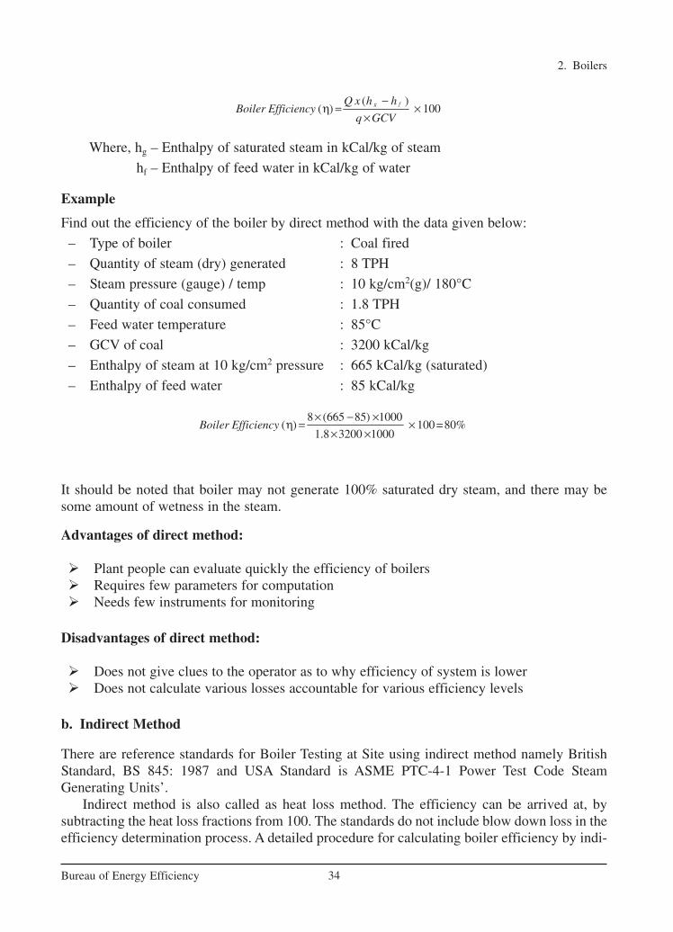
Example
Find out the efficiency of the boiler by direct method with the data given below:
– Type of boiler : Coal fired
– Quantity of steam (dry) generated : 8 TPH
– Steam pressure (gauge) / temp : 10 kg/cm2(g)/ 180°C
– Quantity of coal consumed : 1.8 TPH
– Feed water temperature : 85°C
– GCV of coal : 3200 kCal/kg
– Enthalpy of steam at 10 kg/cm2 pressure : 665 kCal/kg (saturated)
– Enthalpy of feed water : 85 kCal/kg
It should be noted that boiler may not generate 100% saturated dry steam, and there may besome amount of wetness in the steam.
Advantages of direct method:
� Plant people can evaluate quickly the efficiency of boilers� Requires few parameters for computation� Needs few instruments for monitoring
Disadvantages of direct method:
� Does not give clues to the operator as to why efficiency of system is lower� Does not calculate various losses accountable for various efficiency levels
b. Indirect Method
There are reference standards for Boiler Testing at Site using indirect method namely BritishStandard, BS 845: 1987 and USA Standard is ASME PTC-4-1 Power Test Code SteamGenerating Units’.
Indirect method is also called as heat loss method. The efficiency can be arrived at, bysubtracting the heat loss fractions from 100. The standards do not include blow down loss in theefficiency determination process. A detailed procedure for calculating boiler efficiency by indi-
8 (665 85) 1000( ) 100 =80%
1.8 3200 1000Boiler Efficiency
× − ×η = ×
× ×
( )( ) 100g fQ x h h
Boiler Efficiencyq GCV
−η = ×
×
2. Boilers
34Bureau of Energy Efficiency
Ch-02.qxd 2/23/2005 11:21 AM Page 34

rect method is given below. However, it may be noted that the practicing energy mangers inindustries prefer simpler calculation procedures.
The principle losses that occur in a boiler are:
• Loss of heat due to dry fluegas • Loss of heat due to moisture in fuel and combustion air• Loss of heat due to combustion of hydrogen • Loss of heat due to radiation • Loss of heat due to unburnt
In the above, loss due to moisture in fuel and the loss due to combustion of hydrogen aredependent on the fuel, and cannot be controlled by design.
The data required for calculation of boiler efficiency using indirect method are:
• Ultimate analysis of fuel (H2, O2, S, C, moisture content, ash content)• Percentage of Oxygen or CO2 in the flue gas• Flue gas temperature in °C (Tf)• Ambient temperature in °C (Ta) & humidity of air in kg/kg of dry air • GCV of fuel in kCal/kg• Percentage combustible in ash (in case of solid fuels)• GCV of ash in kCal/kg (in case of solid fuels)
Solution :
Theoretical air requirement
=[(11.6 × C) + {34.8 × (H2 – O2/8)} + (4.35 × S)]/100 kg/kg of fuel
Excess Air supplied (EA) =
Actual mass of air supplied/ kg of fuel (AAS) = {1 + EA/100} × theoretical air
m × Cp × (Tf – Ta ) × 100i. Percentage heat loss due to dry flue gas =
GCV of fuel
m = mass of dry flue gas in kg/kg of fuel
m = Combustion products from fuel: CO2 + SO2 + Nitrogen in fuel + Nitrogen in the actualmass of air supplied + O2 in flue gas. (H2O/Water vapour in the flue gas should not beconsidered)
Cp = Specific heat of flue gas (0.23 kCal/kg °C)
ii. Percentage heat loss due to evaporation of water formed due to H2 in fuel
2 p f a9 H {584 C (T -T )} 100
GCV of fuel
× × += ×
2
2
%100
21 %
O
O×
−
2. Boilers
35Bureau of Energy Efficiency
Ch-02.qxd 2/23/2005 11:21 AM Page 35

Where, H2 - kg of H2 in 1 kg of fuelCp - Specific heat of superheated steam (0.45 kCal/kg °C)
iii. Percentage heat loss due to evaporation of moisture present in fuel
Where, M – kg of moisture in 1kg of fuel
Cp – Specific heat of superheated steam (0.45 kCal/kg)°C
584 is the latent heat corresponding to the partial pressure of water vapour.
iv. Percentage heat loss due to moisture present in air
Cp – Specific heat of superheated steam (0.45 kCal/kg °C)
v. Percentage heat loss due to unburnt in fly ash
vi. Percentage heat loss due to unburnt in bottom ash
vii. Percentage heat loss due to radiation and other unaccounted loss
The actual radiation and convection losses are difficult to assess because of particularemissivity of various surfaces, its inclination, air flow pattern etc. In a relatively small boiler,with a capacity of 10 MW, the radiation and unaccounted losses could amount to between 1%and 2% of the gross calorific value of the fuel, while in a 500 MW boiler, values between 0.2%to 1% are typical. The loss may be assumed appropriately depending on the surface condition.
Example: The following are the data collected for a typical oil fired boiler. Find out the effi-ciency of the boiler by indirect method and Boiler Evaporation ratio.
• Type of boiler : Oil fired
Efficiency of boiler (η) = 100 - (i + ii + iii + iv + v + vi + vii)
Total ash collected / kg of fuel burnt G.C.V of bottom ash100
GCV of fuel
×= ×
Total ash collected / kg of fuel burnt G.C.V of fly ash100
GCV of fuel
×= ×
p f a C x (T -T ) 100
GCV of fuel
AAS humidity factor× ×= ×
p f aM x {584 C (T -T )} 100
GCV of fuelx
+=
2. Boilers
36Bureau of Energy Efficiency
Ch-02.qxd 2/23/2005 11:21 AM Page 36

• Ultimate analysis of Oil C : 84.0 % H2 : 12.0 %S : 3.0 % O2 : 1.0 %
• GCV of Oil : 10200 kCal/kg• Steam Generation Pressure : 7kg/cm2(g)-saturated• Enthalpy of steam : 660 kCal/kg• Feed water temperature : 60 °C• Percentage of Oxygen in flue gas : 7• Percentage of CO2 in flue gas : 11• Flue gas temperature (Tf) : 220 °C• Ambient temperature (Ta) : 27 °C • Humidity of air : 0.018 kg/kg of dry air
Solution
Step-1: Find the theoretical air requirement
kg/kg of oil
kg/kg of oil
=14 kg of air/kg of oil
Step-2: Find the %Excess air supplied
Excess air supplied (EA) = (O2 × 100)/(21-O2)
= (7 × 100)/(21-7)
= 50%
Step-3: Find the Actual mass of air supplied
Actual mass of air supplied /kg of fuel = [ 1 + EA/100] x Theoritical Air
(AAS)
= [1 + 50/100] x 14
= 1.5 x 14
= 21 kg of air/kg of oil
Step-4: Estimation of all losses
i. Dry flue gas lossm × Cp × (Tf – Ta ) × 100
Percentage heat loss due to dry flue gas =GCV of fuel
m= mass of CO2 + mass of SO2 + mass of N2 + mass of O2
=[(11.6 × 84) + [{34.8 × (12 – 1/8)} + (4.35 × 3)]/100
2 2[(11.6 ) {34.8 ( /8)} (4.35 )] /100C H O S= × + × − + ×
2. Boilers
37Bureau of Energy Efficiency
Ch-02.qxd 2/23/2005 11:21 AM Page 37

m = 21 kg / kg of oil
Percentage heat loss due to dry flue gas = = 9.14 %
Alternatively a simple method can be used for determining the dry flue gas loss asgiven below.
m × Cp × (Tf – Ta ) × 100a) Percentage heat loss due to dry flue gas =
GCV of fuel
Total mass of flue gas (m) = mass of actual air supplied + mass of fuel supplied
= 21 + 1 = 22
%Dry flue gas loss =
ii. Heat loss due to evaporation of water formed due to H2 in fuel
9 × H2 {584 + Cp (Tf – Ta)}× 100=
GCV of fuel
0.84 44 0.03 64 21 77 23m (21 14)
12 32 100 100
× × × = + + + − ×
2. Boilers
38Bureau of Energy Efficiency
Where, H2 - percentage of H2 in fuel
9 × 12 {584 + 0.45 (220 – 27)}× 100=
10200
= 7.10%
iii. Heat loss due to moisture present in air
AAS × humidity × Cp × (Tf – Ta) × 100=
GCV of fuel
= = 0.322%
iv. Heat loss due to radiation and other unaccounted losses
For a small boiler it is estimated to be 2%
Boiler Efficiency
i. Heat loss due to dry flue gas : 9.14%
ii. Heat loss due to evaporation of water formed due to H2 in fuel : 7.10 %
iii. Heat loss due to moisture present in air : 0.322 %
21 0.23 (220 27)100
10200
x xx
−
22 0.23 (220 27)100 9.57%
10200
x xx
− =
21 0.018 0.45 (220 27)100
10200
x x xx
−
Ch-02.qxd 2/23/2005 11:21 AM Page 38

iv. Heat loss due to radiation and other unaccounted loss : 2%
Boiler Efficiency = 100- [9.14 + 7.10 + 0.322 + 2]
= 100 – 18.56 = 81 %(app)
Evaporation Ratio = Heat utilised for steam generation/Heat addition to the steam
= 10200 × 0.83/ (660-60)
= 14.11
Boiler Evaporation Ratio
Evaporation ratio means kilogram of steam generated per kilogram of fuel consumed.
Typical Examples: Coal fired boiler: 6
Oil fired boiler: 13
i.e 1 kg of coal can generate 6 kg of steam
1 kg of oil can generate 13 kg of steam
However, this figure will depend upon type of boiler, calorific value of the fuel andassociated efficiencies.
2.5 Boiler BlowdownWhen water is boiled and steam is generated, any dissolved solids contained in the water remainin the boiler. If more solids are put in with the feed water, they will concentrate and may even-tually reach a level where their solubility in the water is exceeded and they deposit from thesolution. Above a certain level of concentration, these solids encourage foaming and cause car-ryover of water into the steam. The deposits also lead to scale formation inside the boiler, result-ing in localized overheating and finally causing boiler tube failure.
It is, therefore, necessary to control the level of concentration of the solids and this isachieved by the process of ‘blowing down’, where a certain volume of water is blown off andis automatically replaced by feed water – thus maintaining the optimum level of total dissolvedsolids (TDS) in the boiler water. Blow down is necessary to protect the surfaces of the heatexchanger in the boiler. However, blow down can be a significant source of heat loss, if improperly carried out. The maximum amount of total dissolved solids (TDS) concentrationpermissible in various types of boilers is given in Table 2.1.
TABLE 2.1 RECOMMENDED TDS LEVELS FOR VARIOUS BOILERS
Boiler Type Maximum TDS (ppm)*
1. Lancashire 10,000 ppm
2. Smoke and water tube boilers (12 kg/cm2) 5,000 ppm
3. Low pressure Water tube boiler 2000–3000
4. High Pressure Water tube boiler with superheater etc. 3,000–3,500 ppm
5. Package and economic boilers 3,000 ppm
6. Coil boilers and steam generators 2000 (in the feed water
Note: Refer guidelines specified by manufacturer for more details*parts per million
2. Boilers
39Bureau of Energy Efficiency
Ch-02.qxd 2/23/2005 11:21 AM Page 39

purity at given steam load. Once blow down valve is set for a given conditions, there is no needfor regular operator intervention.
Conductivity as Indicator of Boiler Water Quality
Since it is tedious and time consuming to measure total dissolved solids (TDS) in boiler watersystem, conductivity measurement is used for monitoring the overall TDS present in the boiler.A rise in conductivity indicates a rise in the “contamination” of the boiler water.
Conventional methods for blowing down the boiler depend on two kinds of blowdown –intermittent and continuous
Intermittent Blowdown
The intermittent blown down is given by manually operating a valve fitted to discharge pipe atthe lowest point of boiler shell to reduce parameters (TDS or conductivity, pH, Silica andPhosphates concentration) within prescribed limits so that steam quality is not likely to beaffected. In intermittent blowdown, a large diameter line is opened for a short period of time,the time being based on a thumb rule such as “once in a shift for 2 minutes”.
Intermittent blowdown requires large short-term increases in the amount of feed water putinto the boiler, and hence may necessitate larger feed water pumps than if continuous blowdown is used. Also, TDS level will be varying, thereby causing fluctuations of the water levelin the boiler due to changes in steam bubble size and distribution which accompany changes inconcentration of solids. Also substantial amount of heat energy is lost with intermittentblowdown.
Continuous Blowdown
There is a steady and constant dispatch of small stream of concentrated boiler water, andreplacement by steady and constant inflow of feed water. This ensures constant TDS and steam
2. Boilers
40Bureau of Energy Efficiency
Figure 2.9 Blowdown Heat Recovery System
Ch-02.qxd 2/23/2005 11:21 AM Page 40
2. Boilers
41Bureau of Energy Efficiency
Even though large quantities of heat are wasted, opportunity exists for recovering this heatby blowing into a flash tank and generating flash steam. This flash steam can be used for pre-heating boiler feed water or for any other purpose (see Figure 2.9 for blow down heat recoverysystem). This type of blow down is common in high-pressure boilers.
Blowdown calculations
The quantity of blowdown required to control boiler water solids concentration is calculated byusing the following formula:
Blow down (%) = Feed water TDS × % Make up water
Maximum Permissible TDS in Boiler water
If maximum permissible limit of TDS as in a package boiler is 3000 ppm, percentage makeup water is 10% and TDS in feed water is 300 ppm, then the percentage blow down is given as:
= 300 x 10/ 3000
= 1%
If boiler evaporation rate is 3000 kg/hr then required blow down rate is:3000 x 1
100
= 30 kg/hr
Benefits of Blowdown
Good boiler blow down control can significantly reduce treatment and operational costs thatinclude:
– Lower pretreatment costs– Less make-up water consumption– Reduced maintenance downtime– Increased boiler life– Lower consumption of treatment chemicals
2.6 Boiler Water Treatment
Producing quality steam on demand depends on properly managed water treatment to controlsteam purity, deposits and corrosion. A boiler is the sump of the boiler system. It ultimatelyreceives all of the pre-boiler contaminants. Boiler performance, efficiency, and service life aredirect products of selecting and controlling feed water used in the boiler.
When feed water enters the boiler, the elevated temperatures and pressures cause the components of water to behave differently. Most of the components in the feed water are soluble. However, under heat and pressure most of the soluble components come out of
Ch-02.qxd 2/23/2005 11:21 AM Page 41

solution as particulate solids, sometimes in crystallized forms and other times as amorphousparticles. When solubility of a specific component in water is exceeded, scale or depositsdevelop. The boiler water must be sufficiently free of deposit forming solids to allow rapid andefficient heat transfer and it must not be corrosive to the boiler metal.
Deposit Control
Deposits in boilers may result from hardness contamination of feed water and corrosion products from the condensate and feed water system. Hardness contamination of the feed watermay arise due to deficient softener system.
Deposits and corrosion result in efficiency losses and may result in boiler tube failures andinability to produce steam. Deposits act as insulators and slows heat transfer. Large amounts ofdeposits throughout the boiler could reduce the heat transfer enough to reduce the boiler effi-ciency significantly. Different type of deposits affects the boiler efficiency differently. Thus itmay be useful to analyse the deposits for its characteristics. The insulating effect of depositscauses the boiler metal temperature to rise and may lead to tube-failure by overheating.
Impurities Causing Deposits
The most important chemicals contained in water that influences the formation of deposits inthe boilers are the salts of calcium and magnesium, which are known as hardness salts.
Calcium and magnesium bicarbonate dissolve in water to form an alkaline solution andthese salts are known as alkaline hardness. They decompose upon heating, releasing carbondioxide and forming a soft sludge, which settles out. These are called temporary hardness-hard-ness that can be removed by boiling.
Calcium and magnesium sulphates, chlorides and nitrates, etc. when dissolved in water arechemically neutral and are known as non-alkaline hardness. These are called permanent hard-ness and form hard scales on boiler surfaces, which are difficult to remove. Non-alkalinity hard-ness chemicals fall out the solution due to reduction in solubility as the temperature rises, byconcentration due to evaporation which takes place within the boiler, or by chemical change toa less soluble compound.
Silica
The presence of silica in boiler water can rise to formation of hard silicate scales. It can alsoassociate with calcium and magnesium salts, forming calcium and magnesium silicates of verylow thermal conductivity. Silica can give rise to deposits on steam turbine blades, after beencarried over either in droplets of water in steam, or in volatile form in steam at higher pressures.
Two major types of boiler water treatment are: Internal water treatment and External watertreatment.
Internal Water Treatment
Internal treatment is carried out by adding chemicals to boiler to prevent the formation of scaleby converting the scale-forming compounds to free-flowing sludges, which can be removed byblowdown. This method is limited to boilers, where feed water is low in hardness salts, to lowpressures- high TDS content in boiler water is tolerated, and when only small quantity of wateris required to be treated. If these conditions are not applied, then high rates of blowdown are
2. Boilers
42Bureau of Energy Efficiency
Ch-02.qxd 2/23/2005 11:21 AM Page 42

2. Boilers
43Bureau of Energy Efficiency
required to dispose off the sludge. They become uneconomical from heat and water loss con-sideration.
Different waters require different chemicals. Sodium carbonate, sodium aluminate, sodiumphosphate, sodium sulphite and compounds of vegetable or inorganic origin are all used for thispurpose. Proprietary chemicals are available to suit various water conditions. The specialistmust be consulted to determine the most suitable chemicals to use in each case. Internal treat-ment alone is not recommended.
External Water Treatment
External treatment is used to remove suspended solids, dissolved solids (particularly thecalcium and magnesium ions which are a major cause of scale formation) and dissolved gases(oxygen and carbon dioxide).
The external treatment processes available are: ion exchange; demineralization; reverseosmosis and de-aeration. Before any of these are used, it is necessary to remove suspendedsolids and colour from the raw water, because these may foul the resins used in the subsequenttreatment sections.
Methods of pre-treatment include simple sedimentation in settling tanks or settling inclarifiers with aid of coagulants and flocculants. Pressure sand filters, with spray aeration toremove carbon dioxide and iron, may be used to remove metal salts from bore well water.
The first stage of treatment is to remove hardness salt and possibly non-hardness salts.Removal of only hardness salts is called softening, while total removal of salts from solution iscalled demineralization.
The processes are:
Ion-exchange process (Softener Plant)
In ion-exchange process, the hardness isremoved as the water passes through bed ofnatural zeolite or synthetic resin and withoutthe formation of any precipitate. The simplesttype is ‘base exchange’ in which calcium andmagnesium ions are exchanged for sodiumions. After saturation regeneration is done withsodium chloride. The sodium salts being soluble, do not form scales in boilers. Since baseexchanger only replaces the calcium and magnesium with sodium, it does not reduce the TDScontent, and blowdown quantity. It also does not reduce the alkalinity.
Demineralization is the complete removal of all salts. This is achieved by using a “cation”resin, which exchanges the cations in the raw water with hydrogen ions, producinghydrochloric, sulphuric and carbonic acid. Carbonic acid is removed in degassing tower inwhich air is blown through the acid water. Following this, the water passes through an “anion”resin which exchanges anions with the mineral acid (e.g. sulphuric acid) and forms water.Regeneration of cations and anions is necessary at intervals using, typically, mineral acid andcaustic soda respectively. The complete removal of silica can be achieved by correct choice ofanion resin.
Softening reaction:Na2R + Ca(HCO3)2 « CaR + 2 Na(HCO3)
Regeneration reactionCaR + 2 NaCl « Na2R + CaCl2
Ch-02.qxd 2/23/2005 11:21 AM Page 43

2. Boilers
44Bureau of Energy Efficiency
Ion exchange processes can be used for almost total demineralization if required, as is thecase in large electric power plant boilers
De-aeration
In de-aeration, dissolved gases, such as oxygenand carbon dioxide, are expelled by preheatingthe feed water before it enters the boiler.
All natural waters contain dissolved gases insolution. Certain gases, such as carbon dioxideand oxygen, greatly increase corrosion. Whenheated in boiler systems, carbon dioxide (CO2)and oxygen (O2) are released as gases and com-bine with water (H2O) to form carbonic acid,(H2CO3).
Removal of oxygen, carbon dioxide andother non-condensable gases from boiler feed-water is vital to boiler equipment longevity aswell as safety of operation. Carbonic acid cor-rodes metal reducing the life of equipment andpiping. It also dissolves iron (Fe) which when returned to the boiler precipitates and causesscaling on the boiler and tubes. This scale not only contributes to reducing the life of the equip-ment but also increases the amount of energy needed to achieve heat transfer.
De-aeration can be done by mechanical de-aeration, by chemical de-deration or by bothtogether.
Mechanical de-aeration
Mechanical de-aeration for the removal of these dissolved gases is typically utilized prior to theaddition of chemical oxygen scavengers. Mechanical de-aeration is based on Charles’ andHenry’s laws of physics. Simplified, these laws state that removal of oxygen and carbon dioxidecan be accomplished by heating the boiler feed water, which reduces the concentration of oxy-gen and carbon dioxide in the atmosphere surrounding the feed water. Mechanical de-aerationcan be the most economical. They operate at the boiling point of water at the pressure in the de-aerator. They can be of vacuum or pressure type.
The vacuum type of de-aerator operates below atmospheric pressure, at about 82 °C, canreduce the oxygen content in water to less than 0.02 mg/litre. Vacuum pumps or steam ejectorsare required to maintain the vacuum.
The pressure-type de-aerators operates by allowing steam into the feed water through apressure control valve to maintain the desired operating pressure, and hence temperature at aminimum of 105 °C. The steam raises the water temperature causing the release of O2 and CO2 gases thatare then vented from the system. This type can reduce the oxygen content to 0.005 mg/litre.
Where excess low-pressure steam is available, the operating pressure can be selected tomake use of this steam and hence improve fuel economy. In boiler systems, steam is preferred
Figure 2.10 Deaerator
Ch-02.qxd 2/23/2005 11:21 AM Page 44

2. Boilers
45Bureau of Energy Efficiency
for de-aeration because:
– Steam is essentially free from O2 and CO2,– Steam is readily available – Steam adds the heat required to complete the reaction.
Chemical de-Aeration
While the most efficient mechanical deaerators reduce oxygen to very low levels (0.005 mg/litre), even trace amounts of oxygen may cause corrosion damage to a system.Consequently, good operating practice requires removal of that trace oxygen with a chemicaloxygen scavenger such as sodium sulfite or hydrazine. Sodium sulphite reacts with oxygen toform sodium sulphate, which increases the TDS in the boiler water and hence increases theblowdown requirements and make-up water quality. Hydrazine reacts with oxygen to formnitrogen and water. It is invariably used in high pressures boilers when low boiler water solidsare necessary, as it does not increase the TDS of the boiler water.
Reverse Osmosis
Reverse osmosis uses the fact that when solutions of differing concentrations are separated by asemi-permeable membrane, water from less concentrated solution passes through the membraneto dilute the liquid of high concentration. If the solution of high concentration is pressurized, theprocess is reversed and the water from the solution of high concentration flows to the weaker solu-tion. This is known as reverse osmosis. The quality of water produced depends upon the concen-tration of the solution on the high-pressure side and pressure differential ascross the membrane.This process is suitable for waters with very high TDS, such as sea water.
The semipermeable nature of the membrane allows thewater to pass much more readi-ly than the dissolved minerals.Since the water in the less con-centrated solution seeks todilute the more concentratedsolution, the water passagethrough the membranegenerates a noticeable headdifference between the twosolutions. This head differenceis a measure of the concentra-tion difference of the two solu-tions and is referred to as theosmotic pressure difference.
Ch-02.qxd 2/23/2005 11:21 AM Page 45

2. Boilers
46Bureau of Energy Efficiency
When a pressure is applied tothe concentrated solutionwhich is great that the osmoticpressure difference, thedirection of water passagethrough the membrane isreversed and the process thatwe refer to as reverse osmosisis established. That is, themembrane's ability toselectively pass water isunchanged, only the directionof the water flow is changed.
The feed water and concentrate(reject stream) ports illustratesa continuously operating ROsystem.
Figure 2.11 Reverse Osmosis
Recommended boiler and feed water quality
The impurities found in boiler water depend on the untreated feed water quality, the treatmentprocess used and the boiler operating procedures. As a general rule, the higher the boiler oper-ating pressure, the greater will be the sensitivity to impurities. Recommended feed water andboiler water limits are shown in Table 2.2 and Table 2.3.
Ch-02.qxd 2/23/2005 11:21 AM Page 46
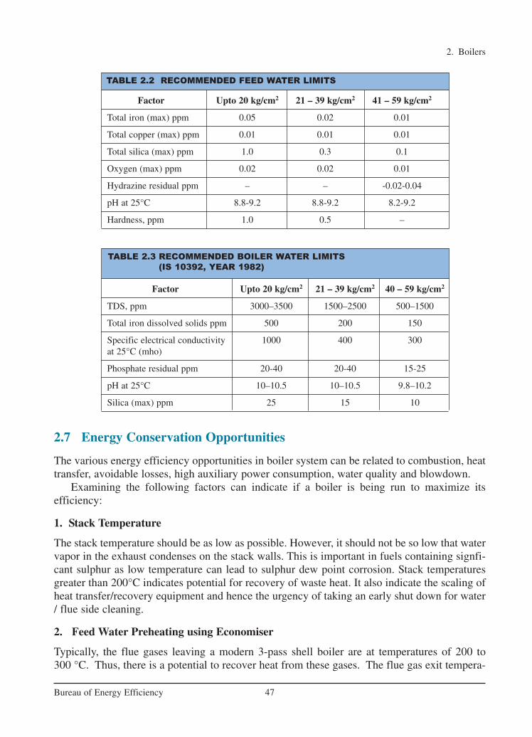
2. Boilers
47Bureau of Energy Efficiency
Factor Upto 20 kg/cm2 21 – 39 kg/cm2 41 – 59 kg/cm2
Total iron (max) ppm 0.05 0.02 0.01
Total copper (max) ppm 0.01 0.01 0.01
Total silica (max) ppm 1.0 0.3 0.1
Oxygen (max) ppm 0.02 0.02 0.01
Hydrazine residual ppm – – -0.02-0.04
pH at 25°C 8.8-9.2 8.8-9.2 8.2-9.2
Hardness, ppm 1.0 0.5 –
TABLE 2.3 RECOMMENDED BOILER WATER LIMITS
(IS 10392, YEAR 1982)
Factor Upto 20 kg/cm2 21 – 39 kg/cm2 40 – 59 kg/cm2
TDS, ppm 3000–3500 1500–2500 500–1500
Total iron dissolved solids ppm 500 200 150
Specific electrical conductivity 1000 400 300at 25°C (mho)
Phosphate residual ppm 20-40 20-40 15-25
pH at 25°C 10–10.5 10–10.5 9.8–10.2
Silica (max) ppm 25 15 10
TABLE 2.2 RECOMMENDED FEED WATER LIMITS
2.7 Energy Conservation Opportunities
The various energy efficiency opportunities in boiler system can be related to combustion, heattransfer, avoidable losses, high auxiliary power consumption, water quality and blowdown.
Examining the following factors can indicate if a boiler is being run to maximize itsefficiency:
1. Stack Temperature
The stack temperature should be as low as possible. However, it should not be so low that watervapor in the exhaust condenses on the stack walls. This is important in fuels containing signfi-cant sulphur as low temperature can lead to sulphur dew point corrosion. Stack temperaturesgreater than 200°C indicates potential for recovery of waste heat. It also indicate the scaling ofheat transfer/recovery equipment and hence the urgency of taking an early shut down for water/ flue side cleaning.
2. Feed Water Preheating using Economiser
Typically, the flue gases leaving a modern 3-pass shell boiler are at temperatures of 200 to 300 °C. Thus, there is a potential to recover heat from these gases. The flue gas exit tempera-
Ch-02.qxd 2/23/2005 11:21 AM Page 47

2. Boilers
48Bureau of Energy Efficiency
ture from a boiler is usually maintained at a minimum of 200 °C, so that the sulphur oxides inthe flue gas do not condense and cause corrosion in heat transfer surfaces. When a clean fuelsuch as natural gas, LPG or gas oil is used, the economy of heat recovery must be worked out,as the flue gas temperature may be well below 200 °C.
The potential for energy saving depends on the type of boiler installed and the fuel used.For a typically older model shell boiler, with a flue gas exit temperature of 260 °C, aneconomizer could be used to reduce it to 200 °C, increasing the feed water temperature by 15 °C. Increase in overall thermal efficiency would be in the order of 3%. For a modern 3-passshell boiler firing natural gas with a flue gas exit temperature of 140 °C a condensingeconomizer would reduce the exit temperature to 65 °C increasing thermal efficiency by 5%.
3. Combustion Air Preheat
Combustion air preheating is an alternative to feedwater heating. In order to improve thermalefficiency by 1%, the combustion air temperature must be raised by 20 °C. Most gas and oilburners used in a boiler plant are not designed for high air preheat temperatures.
Modern burners can withstand much higher combustion air preheat, so it is possible to con-sider such units as heat exchangers in the exit flue as an alternative to an economizer, wheneither space or a high feed water return temperature make it viable.
4. Incomplete Combustion
Incomplete combustion can arise from a shortage of air or surplus of fuel or poordistribution of fuel. It is usually obvious from the colour or smoke, and must be correctedimmediately.
In the case of oil and gas fired systems, CO or smoke (for oil fired systems only) withnormal or high excess air indicates burner system problems. A more frequent cause of incom-plete combustion is the poor mixing of fuel and air at the burner. Poor oil fires can result fromimproper viscosity, worn tips, carbonization on tips and deterioration of diffusers or spinnerplates.
With coal firing, unburned carbon can comprise a big loss. It occurs as grit carry-over orcarbon-in-ash and may amount to more than 2% of the heat supplied to the boiler. Non uniformfuel size could be one of the reasons for incomplete combustion. In chain grate stokers, largelumps will not burn out completely, while small pieces and fines may block the air passage, thuscausing poor air distribution. In sprinkler stokers, stoker grate condition, fuel distributors, windbox air regulation and over-fire systems can affect carbon loss. Increase in the fines inpulverized coal also increases carbon loss.
5. Excess Air Control
The Table 2.4 gives the theoretical amount of air required for combustion of various types of fuel.Excess air is required in all practical cases to ensure complete combustion, to allow for the
normal variations in combustion and to ensure satisfactory stack conditions for some fuels. The optimum excess air level for maximum boiler efficiency occurs when the sum of the loss-es due to incomplete combustion and loss due to heat in flue gases is minimum. This levelvaries with furnace design, type of burner, fuel and process variables. It can be determined byconducting tests with different air fuel ratios.
Ch-02.qxd 2/23/2005 11:21 AM Page 48

2. Boilers
49Bureau of Energy Efficiency
Typical values of excess air supplied for various fuels are given in Table – 2.5.
TABLE 2.5 EXCESS AIR LEVELS FOR DIFFERENT FUELS
Fuel Type of Furnace or Burners Excess Air (% by wt)
Pulverised coal Completely water-cooled furnace for slag-tap or dry-ash removal 15–20
Partially water-cooled furnace for dry-ash removal 15–40
Coal Spreader stoker 30–60
Water-cooler vibrating-grate stokers 30–60
Chain-grate and traveling-gate stokers 15–50
Underfeed stoker 20–50
Fuel oil Oil burners, register type 15–20
Multi-fuel burners and flat-flame 20–30
Natural gas High pressure burner 5–7
Wood Dutch over (10–23% through grates) and Hofft type 20–25
Bagasse All furnaces 25–35
Black liquor Recovery furnaces for draft and soda-pulping processes 30–40
Fuel kg of air kg of flue m3 of Theoretical CO2% in fluereq./kg of gas/kg flue/kg CO2% in gas achieved
fuel of fuel of fuel dry flue gas in practice
Solid Fuels
Bagasse 3.2 3.43 2.61 20.65 10–12
Coal (bituminous) 10.8 11.7 9.40 18.70 10–13
Lignite 8.4 9.10 6.97 19.40 9–13
Paddy Husk 4.6 5.63 4.58 19.8 14–15
Wood 5.8 6.4 4.79 20.3 11.13
Liquid Fuels
Furnace Oil 13.90 14.30 11.50 15.0 9–14
LSHS 14.04 14.63 10.79 15.5 9–14
TABLE 2.4 THEORETICAL COMBUSTION DATA – COMMON BOILER FUELS
Controlling excess air to an optimum level always results in reduction in flue gas losses; forevery 1% reduction in excess air there is approximately 0.6% rise in efficiency.
Various methods are available to control the excess air:
• Portable oxygen analysers and draft gauges can be used to make periodic readings to guidethe operator to manually adjust the flow of air for optimum operation. Excess air reductionup to 20% is feasible.
Ch-02.qxd 2/23/2005 11:21 AM Page 49

• The most common method is the continuous oxygen analyzer with a local readout mounteddraft gauge, by which the operator can adjust air flow. A further reduction of 10–15% canbe achieved over the previous system.
• The same continuous oxygen analyzer can have a remote controlled pneumatic damperpositioner, by which the readouts are available in a control room. This enables an operatorto remotely control a number of firing systems simultaneously.
The most sophisticated system is the automatic stack damper control, whose cost is reallyjustified only for large systems.
6. Radiation and Convection Heat Loss
The external surfaces of a shell boiler are hotter than the surroundings. The surfaces thus loseheat to the surroundings depending on the surface area and the difference in temperaturebetween the surface and the surroundings.
The heat loss from the boiler shell is normally a fixed energy loss, irrespective of the boil-er output. With modern boiler designs, this may represent only 1.5% on the gross calorificvalue at full rating, but will increase to around 6%, if the boiler operates at only 25 percentoutput.
Repairing or augmenting insulation can reduce heat loss through boiler walls and piping.
7. Automatic Blowdown Control
Uncontrolled continuous blowdown is very wasteful. Automatic blowdown controls can beinstalled that sense and respond to boiler water conductivity and pH. A 10% blow down in a 15kg/cm2 boiler results in 3% efficiency loss.
8. Reduction of Scaling and Soot Losses
In oil and coal-fired boilers, soot buildup on tubes acts as an insulator against heat transfer. Anysuch deposits should be removed on a regular basis. Elevated stack temperatures may indicateexcessive soot buildup. Also same result will occur due to scaling on the water side.
High exit gas temperatures at normal excess air indicate poor heat transfer performance.This condition can result from a gradual build-up of gas-side or waterside deposits. Watersidedeposits require a review of water treatment procedures and tube cleaning to remove deposits.An estimated 1% efficiency loss occurs with every 22 °C increase in stack temperature.
Stack temperature should be checked and recorded regularly as an indicator of sootdeposits. When the flue gas temperature rises about 20 °C above the temperature for a newlycleaned boiler, it is time to remove the soot deposits. It is, therefore, recommended to install adial type thermometer at the base of the stack to monitor the exhaust flue gas temperature.
It is estimated that 3 mm of soot can cause an increase in fuel consumption by 2.5% due toincreased flue gas temperatures. Periodic off-line cleaning of radiant furnace surfaces, boilertube banks, economizers and air heaters may be necessary to remove stubborn deposits.
9. Reduction of Boiler Steam Pressure
This is an effective means of reducing fuel consumption, if permissible, by as much as 1 to 2%.Lower steam pressure gives a lower saturated steam temperature and without stack heatrecovery, a similar reduction in the temperature of the flue gas temperature results.
2. Boilers
50Bureau of Energy Efficiency
Ch-02.qxd 2/23/2005 11:21 AM Page 50

Steam is generated at pressures normally dictated by the highest pressure / temperaturerequirements for a particular process. In some cases, the process does not operate all the time, andthere are periods when the boiler pressure could be reduced. The energy manager should considerpressure reduction carefully, before recommending it. Adverse effects, such as an increase in watercarryover from the boiler owing to pressure reduction, may negate any potential saving. Pressureshould be reduced in stages, and no more than a 20 percent reduction should be considered.
10. Variable Speed Control for Fans, Blowers and Pumps
Variable speed control is an important means of achieving energy savings. Generally, combus-tion air control is effected by throttling dampers fitted at forced and induced draft fans. Thoughdampers are simple means of control, they lack accuracy, giving poor control characteristics atthe top and bottom of the operating range. In general, if the load characteristic of the boiler isvariable, the possibility of replacing the dampers by a VSD should be evaluated.
11. Effect of Boiler Loading on Efficiency
The maximum efficiency of the boiler does not occur at full load, but at about two-thirds of thefull load. If the load on the boiler decreases further, efficiency also tends to decrease. At zerooutput, the efficiency of the boiler is zero, and any fuel fired is used only to supply the losses.The factors affecting boiler efficiency are:
• As the load falls, so does the value of the mass flow rate of the flue gases through the tubes.This reduction in flow rate for the same heat transfer area, reduced the exit flue gas tem-peratures by a small extent, reducing the sensible heat loss.
• Below half load, most combustion appliances need more excess air to burn the fuelcompletely. This increases the sensible heat loss
In general, efficiency of the boiler reduces significantly below 25% of the rated load and asfar as possible, operation of boilers below this level should be avoided
12. Proper Boiler Scheduling
Since, the optimum efficiency of boilers occurs at 65–85% of full load, it is usually moreefficient, on the whole, to operate a fewer number of boilers at higher loads, than to operate alarge number at low loads.
13. Boiler Replacement
The potential savings from replacing a boiler depend on the anticipated change in overallefficiency. A change in a boiler can be financially attractive if the existing boiler is :
� old and inefficient� not capable of firing cheaper substitution fuel� over or under-sized for present requirements� not designed for ideal loading conditions
The feasibility study should examine all implications of long-term fuel availability andcompany growth plans. All financial and engineering factors should be considered. Since boilerplants traditionally have a useful life of well over 25 years, replacement must be carefully studied.
2. Boilers
51Bureau of Energy Efficiency
Ch-02.qxd 2/23/2005 11:21 AM Page 51

2.8 Case Study
Installing Boiler Economiser
A paper mill retrofitted an economiser to existing boiler. The general specification of the boileris given below:
The thermal efficiency of the boiler was measured and calculated by the indirect methodusing flue gases analyser and data logger. The result is summarised below:
Thermal efficiency : 81%
Flue gas temperature : 315°C
CO2% : 13
CO (ppm) : 167
The temperature in the flue gas is in the range of 315 to 320 °C. The waste heat in the flue gasis recovered by installing an economizer, which transfers waste heat from the flue gases to theboiler feed water. This resulted in a rise in feed water temperature by about 26 °C.
Basic Data
• Average quantity of steam generated ..... : 5 T/hr
• Average flue gas temperature ................ : 315 °C
• Average steam generation / kg of fuel oil : 14 kg
• Feed water inlet temperature ................. : 110 °C
• Fuel oil supply rate................................ : 314 kg/hr
• Flue gas quantity ................................... : 17.4 kg/kg of fuel
Cost Economics
• Quantity of flue gases ............................. : 314 × 17.4 = 5463.6 kg/h
• Quantity of heat available in the : 5463.6 × 0.23 × (315-200) = 144512 kCal/hflue gases
• Rise in the feed water temperature ........... : 26 °C.
• Heat required for pre-heating the : 5000 × 1 × 26 = 130000 kCal/hfeed water
• Saving in terms of furnace oil .....................: 130000/10000 = 13 kg/h
• Annual operating hours ........................... : 8600
• Annual savings of fuel oil ......................... : 8600 × 13 = 111800 kg
Boiler Capacity (T/h) Feed Water Temp (°C) Steam Pressure (bar) Fuel oil
8 110 18 Furnace oil
2. Boilers
52Bureau of Energy Efficiency
Ch-02.qxd 2/23/2005 11:21 AM Page 52

Conclusion
Through recovery of waste heat by installation of an economizer, the paper mill was able tosave 13 kg/hr. of furnace oil, which amounts to about 1,11,800 kg of furnace oil per annum.
2. Boilers
53Bureau of Energy Efficiency
QUESTIONS
1. What is the importance of draft in boilers?
2. What is a balanced draft system?
3. Which is the single major heat loss in boiler?
4. Explain the principle of modulating control in a boiler?
5. Explain the principle of fire tube and water tube boilers?
6. Explain the principles of fluidized bed combustion and pulverized fuel combustion?
7. Name three factors affecting the boiler efficiency and explain briefly?
8. Discuss the various types of draft in boiler system?
9. What do you understand by terminology fire tube and water tube in boiler?
10. Discuss the various types of heat losses in a boiler?
11. How do you measure boiler efficiency using direct method?
12. What do you understand by term evaporation ratio? What are the typical values forcoal and oil-fired boiler?
13. What do you understand by the term ‘Turn Down Ratio’ ?
14. What are the methods available for assessing the boiler efficiency and explainbriefly?
15. How do you assess boiler blow down requirement?
16. Discuss automatic blow down control system?
17. Why blow down is given in boiler?
18. What is the function of de-aerator in boiler?
19. What is the difference between an economizer and an air pre heater?
20. List the 5 energy conservation measures in improving the boiler efficiency withoutinvestment.
21. What is intermittent and continuous blow down?
22. Why is sulphur in coal undesirable?
23. Is moisture in coal wasteful?
24. What is atomisation of fuel oil in combustion?
25. What are the causes for heavy black smoke in a boiler?
Ch-02.qxd 2/23/2005 11:21 AM Page 53

26. 1 kg of water at 25°C is converted in to steam at atmospheric condition. What is thevalue of sensible heat and latent heat added to the steam?
27. For boiler at 8 kg/cm2 (g) steam pressure. The following details are given
Saturation temperature of steam = 170°C
Sensible heat of water = 171 kCal/kg
Latent heat of evaporation = 490 kCal/kg
Moisture content in the steam = 4%
What is the total heat content of the steam?
28. The following are the ultimate analysis for coal: Calculate the stoichiometric airrequirement.
Carbon-38%, Ash-35%, Hydrogen-5% , Sulphur-2%.
For the same data, calculate the theoretical CO2.
If the actual measured CO2 is 8%, find out the excess air levels?
29. A packaged boiler is operating at 5% O2. Find out the excess air level?
30. In a furnace oil fired boiler, the evaporation ratio (kg of steam generated / kg of fur-nace oil) was found to be 20 against a best possible limit of 13. (a) in your opinionwhat could be the reasons for the same? (b) would you like to recommend the userto maintain the same practice and conditions as the evaporation ratio is more than thefeasible limit?
2. Boilers
54Bureau of Energy Efficiency
REFERENCES1. Steam Boiler Room Questions & Answers, Third Edition by Stephen M.Elonka and
Alex Higgins2. Steam Boiler Operation by James J.Jackson, Prentice-Hall Inc, New Jersey, 1980.3. Boilers by Carl D. Shields, McGraw Hill Book Company, U.S, 1961.4. Industrial Heat Generation and Distribution -NIFES Training Manual Issued For CEC –
India Energy Bus Project5. Practical Boiler Water Treatment by Leo.I.Pincus, McGraw Hill Inc, New York, 1962.6. Technical Papers, Boiler Congress-2000 Seminar, 11 & 12 January 20007. Industrial Boilers by David Gunn and Robert Horton, Longman Scientific & Technical,
New York8. Steam Generation, Distribution and Utilisation by TERI, GTZ and EMC9. Efficient Operation of Boilers by National Productivity Council
www.eren.doe.govwww.oit.doe.gov/bestpracticeswww.pcra.orgwww.energy-efficiency.gov.ukwww.actionenergy.org.ukwww.cia.org.ukwww.altenergy.com
Ch-02.qxd 2/23/2005 11:21 AM Page 54

3. STEAM SYSTEM
55Bureau of Energy Efficiency
Syllabus
Steam System: Properties of steam, Assessment of steam distribution losses, Steam leak-ages, Steam trapping, Condensate and flash steam recovery system, Identifying opportu-nities for energy savings.
3.1 Introduction
Steam has been a popular mode of conveying energy since the industrial revolution. Steam isused for generating power and also used in process industries such as sugar, paper, fertilizer,refineries, petrochemicals, chemical, food, synthetic fibre and textiles The following character-istics of steam make it so popular and useful to the industry:
• Highest specific heat and latent heat • Highest heat transfer coefficient • Easy to control and distribute • Cheap and inert
3.2 Properties of SteamWater can exist in the form of solid, liquid and gas as ice, water and steam respectively. If heatenergy is added to water, its temperature rises until a value is reached at which the water can nolonger exist as a liquid. We call this the "saturation" point and with any further addition of energy, some of the water will boil off as steam. This evaporation requires relatively largeamounts of energy, and while it is being added, the water and the steam released are both at thesame temperature. Equally, if steam is made to release the energy that was added to evaporateit, then the steam will condense and water at same temperature will be formed.
Liquid Enthalpy
Liquid enthalpy is the "Enthalpy" (heat energy) in thewater when it has been raised to its boiling point toproduce steam, and is measured in kCal/kg, its symbol is hf. (also known as "Sensible Heat")
Enthalpy of Evaporation (Heat Content of Steam)
The Enthalpy of evaporation is the heat energy to beadded to the water (when it has been raised to its boiling point) in order to change it into steam. Thereis no change in temperature, the steam produced is atthe same temperature as the water from which it isproduced, but the heat energy added to the water changes its state from water into steam at thesame temperature.
The heat required to change the tempera-ture of a substance is called its sensible heat.
If 1 kg of water in a vessel at 25oC i.e. containing heat value of 25 kCals is heatedby adding 75 kCals, the water is brought toboiling point of 100oC.
To change the water to steam an additional 540 kCal would be required. This quantity of heat required to change achemical from the liquid to the gaseous stateis called latent heat.
Ch-03.qxd 2/23/2005 11:22 AM Page 55

3. Steam System
56Bureau of Energy Efficiency
When the steam condenses back into water, itgives up its enthalpy of evaporation, which it hadacquired on changing from water to steam. Theenthalpy of evaporation is measured in kCal/kg. Itssymbol is hfg. Enthalpy of evaporation is also knownas latent heat.
The temperature at which water boils, alsocalled as boiling point or saturation tempera-ture increases as the pressure increases. When water under pressure is heated its saturation temperature rises above 100 °C. Fromthis it is evident that as the steam pressure increases, the usable heat energy in the steam(enthalpy of evaporation), which is given up when the steam condenses, actually decreas-es. The total heat of dry saturated steam or enthalpy of saturated steam is given by sumof the two enthalpies hf +hfg (Refer Table 3.1 and figure 3.1). When the steam containsmoisture the total heat of steam will be hg = hf + χ hfg where χ is the dryness fraction.
The temperature of saturated steam is the same as the water from which it is generated,and corresponds to a fixed and known pressure. Superheat is the addition of heat to dry saturated steam without increase in pressure. The temperature of superheated steam,expressed as degrees above saturation corresponding to the pressure, is referred to as thedegrees of superheat.
The Steam Phase Diagram
The data provided in the steam tables can also be expressed in a graphical form. Figure 3.1illustrates the relationship between the enthalpy and the temperature at various different pressures, and is known as a phase diagram.
Figure 3.1 Steam Phase Diagram
For a boiler is operating at a pressure of 8 kg/cm2, steam saturation temperature is170 oC, and steam enthalpy or total heat ofdry saturated steam is given by:hf +hfg = 171.35 +489.46 = 660.81 kCal/kg.
If the same steam contains 4% moisture, thetotal heat of steam is given by:171.35+ 0.96 x 489.46 = 641.23 kCal/kg
Ch-03.qxd 2/23/2005 11:22 AM Page 56
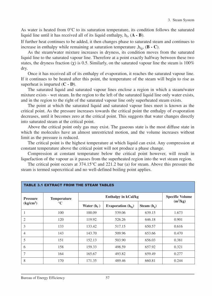
3. Steam System
57Bureau of Energy Efficiency
As water is heated from 0°C to its saturation temperature, its condition follows the saturated liquid line until it has received all of its liquid enthalpy, hf, (A - B).
If further heat continues to be added, it then changes phase to saturated steam and continues toincrease in enthalpy while remaining at saturation temperature ,hfg, (B - C).
As the steam/water mixture increases in dryness, its condition moves from the saturated liquid line to the saturated vapour line. Therefore at a point exactly halfway between these twostates, the dryness fraction (χ) is 0.5. Similarly, on the saturated vapour line the steam is 100%dry.
Once it has received all of its enthalpy of evaporation, it reaches the saturated vapour line.If it continues to be heated after this point, the temperature of the steam will begin to rise assuperheat is imparted (C - D).
The saturated liquid and saturated vapour lines enclose a region in which a steam/watermixture exists - wet steam. In the region to the left of the saturated liquid line only water exists,and in the region to the right of the saturated vapour line only superheated steam exists.
The point at which the saturated liquid and saturated vapour lines meet is known as the critical point. As the pressure increases towards the critical point the enthalpy of evaporationdecreases, until it becomes zero at the critical point. This suggests that water changes directlyinto saturated steam at the critical point.
Above the critical point only gas may exist. The gaseous state is the most diffuse state inwhich the molecules have an almost unrestricted motion, and the volume increases withoutlimit as the pressure is reduced.
The critical point is the highest temperature at which liquid can exist. Any compression atconstant temperature above the critical point will not produce a phase change.
Compression at constant temperature below the critical point however, will result in liquefaction of the vapour as it passes from the superheated region into the wet steam region.
The critical point occurs at 374.15°C and 221.2 bar (a) for steam. Above this pressure thesteam is termed supercritical and no well-defined boiling point applies.
TABLE 3.1 EXTRACT FROM THE STEAM TABLES
Pressure Temperature Enthalpy in kCal/kg Specific Volume
(kg/cm2) °C (m3/kg)Water (hf ) Evaporation (hfg) Steam (hg)
1 100 100.09 539.06 639.15 1.673
2 120 119.92 526.26 646.18 0.901
3 133 133.42 517.15 650.57 0.616
4 143 143.70 509.96 653.66 0.470
5 151 152.13 503.90 656.03 0.381
6 158 159.33 498.59 657.92 0.321
7 164 165.67 493.82 659.49 0.277
8 170 171.35 489.46 660.81 0.244
Ch-03.qxd 2/23/2005 11:22 AM Page 57

3. Steam System
58Bureau of Energy Efficiency
3.3 Steam Distribution
The steam distribution system is the essential link between the steam generator and the steamuser. Whatever the source, an efficient steam distribution system is essential if steam of the rightquality and pressure is to be supplied, in the right quantity, to the steam using equipment.Installation and maintenance of the steam system are important issues, and must be consideredat the design stage.
Figure 3.2 Steam Distribution System
As steam condenses in a process, flow is induced in the supply pipe. Condensate has a verysmall volume compared to the steam, and this causes a pressure drop, which causes the steamto flow through the pipes. The steam generated in the boiler must be conveyed throughpipework to the point where its heat energy is required. Initially there will be one or more mainpipes, or 'steam mains', which carry steam from the boiler in the general direction of the steamusing plant. Smaller branch pipes can then carry the steam to the individual pieces of equip-ment. A typical steam distribution system is shown in Figure 3.2.
The working pressure
The distribution pressure of steam is influenced by a number of factors, but is limited by:
• The maximum safe working pressure of the boiler
• The minimum pressure required at the plant
As steam passes through the distribution pipework, it will inevitably lose pressure due to:
• Frictional resistance within the pipework
• Condensation within the pipework as heat is transferred to the environment.
Therefore allowance should be made for this pressure loss when deciding upon the initial distribution pressure.
Ch-03.qxd 2/23/2005 11:22 AM Page 58

3. Steam System
59Bureau of Energy Efficiency
Features of Steam Piping
General layout and location of steam consuming equipment is of great importance in efficientdistribution of steam. Steam pipes should be laid by the shortest possible distance rather thanto follow a building layout or road etc. However, this may come in the way of aesthetic designand architect's plans and a compromise may be necessary while laying new pipes.
Apart from proper sizing of pipe lines, provision must be made for proper draining of condensate which is bound to form as steam travels along the pipe.
For example, a 100 mm well lagged pipe of 30-meter length carrying steam at 7 kg/cm2
pressure can condense nearly 10 kg. of water in the pipe in one hour unless it is removed fromthe pipe through traps.
The pipes should run with a fall of not less than 12.5 mm in 3 meter in the direction of flow.There should also be large pockets in the pipes to enable water to collect otherwise water willbe carried along with steam. These drain pockets should be provided at every 30 to 50 metersand at any low point in the pipe network. The pocket should be fitted with a trap to dischargethe condensate. Necessary expansion loops are required to take care of the expansion of pipeswhen they get heated up. Automatic air vents should be fixed at the dead end of steam mains,which will allow removal of air which will tend to accumulate.
3.4 Steam Pipe Sizing and Design
Any modification and alteration in the existing steam piping, for supplying higher quality steamat right pressure and quantity must consider the following points:
Pipe Sizing
The objective of the steam distribution system is to supply steam at the correct pressure to thepoint of use. It follows, therefore, that pressure drop through the distribution system is animportant feature.
Proper sizing of steam pipelines help in minimizing pressure drop. The velocities for various types of steam are:
Superheated 50–70 m/sec
Saturated 30–40 m/sec
Wet or Exhaust 20–30 m/sec
Figure 3.3 Draining Condensate from Mains
Ch-03.qxd 2/23/2005 11:22 AM Page 59

3. Steam System
60Bureau of Energy Efficiency
For fluid flow to occur, there must be more energy at Point 1 than Point 2 (see Figure 3.4 ). Thedifference in energy is used to overcome frictional resistance between the pipe and the flowingfluid.
This is illustrated by the equation
Where:
hf = Head loss to friction (m)
f = Friction factor (dimensionless)
L = Length (m)
u = Flow velocity (m/s)
g = Gravitational constant (9.81 m/s²)
D = Pipe diameter (m)
It is useful to remember that:
• Head loss to friction (hf) is proportional to the velocity squared (u²).
• The friction factor (f) is an experimental coefficient which is affected by factors including:
• The Reynolds Number (which is affected by velocity).
• The reciprocal of velocity².
Figure 3.4 Pressure Drop in Steam Pipes
Ch-03.qxd 2/23/2005 11:22 AM Page 60

3. Steam System
61Bureau of Energy Efficiency
Because the values for 'f' are quite complex, they are usually obtained from charts.
Example - Water pipe
Determine the difference in pressure between two points 1 km apart in a 150 mm bore hori-zontal pipework system. The water flowrate is 45 m³/h at 15°C and the friction factor for thispipe is taken as 0.005.
3
2
3
2
2
f
2
f
f
Volumeflowrate ( m s)Velocity ( m s) =
Crosssectionalarea (m )
45m h 4Velocity =
3600s h 0.15
Velocity = 0.71m s
4f Luh
2gD
4 0.005 1000m 0.71h
2 9.81 0.15h 3.43m 0.34bar
π×
× ×
=
× × ×=× ×
= ≈
Guide for proper drainage and layout of steam lines:
1. The steam mains should be run with a falling slope of not less that 125 mm for every 30metres length in the direction of the steam flow.
2. Drain points should be provided at intervals of 30–45 metres along the main.3. Drain points should also be provided at low points in the mains and where the steam
main rises. Ideal locations are the bottom of expansion joints and before reduction andstop valves.
4. Drain points in the main lines should be through an equal tee connection only.5. It is preferable to choose open bucket or TD traps on account of their resilience.6. The branch lines from the mains should always be connected at the top. Otherwise,
the branch line itself will act as a drain for the condensate.7. Insecure supports as well as an alteration in level can lead to formation of water
pockets in steam, leading to wet steam delivery. Providing proper vertical and supporthangers helps overcome such eventualities.
8. Expansion loops are required to accommodate the expansion of steam lines while starting from cold.
9. To ensure dry steam in the process equipment and in branch lines, steam separators canbe installed as required.
Ch-03.qxd 2/23/2005 11:22 AM Page 61

3. Steam System
62Bureau of Energy Efficiency
In practice whether for water pipes or steam pipes, a balance is drawn between pipe size andpressure loss. The steam piping should be sized, based on permissible velocity and the available pressure drop in the line. Selecting a higher pipe size will reduce the pressure dropand thus the energy cost. However, higher pipe size will increase the initial installation cost. Byuse of smaller pipe size, even though the installation cost can be reduced, the energy cost willincrease due to higher-pressure drop. It is to be noted that the pressure drop change will beinversely proportional to the 5th power of diameter change. Hence, care should be taken inselecting the optimum pipe size.
Pipe Redundancy
All redundant (piping which are no longer needed) pipelines must be eliminated, which couldbe, at times, upto 10–15 % of total length. This could reduce steam distribution losses significantly. The pipe routing shall be made for transmission of steam in the shortest possibleway, so as to reduce the pressure drop in the system, thus saving the energy. However, careshould be taken that, the pipe routing shall be flexible enough to take thermal expansion and tokeep the terminal point loads, within the allowable limit.
3.5 Proper Selection, Operation and Maintenance of Steam Traps
The purpose of installing the steam traps is to obtain fast heating of the product and equipmentby keeping the steam lines and equipment free of condensate, air and non-condensable gases.A steam trap is a valve device that discharges condensate and air from the line or piece of equip-ment without discharging the steam.
Functions of Steam Traps
The three important functions of steam traps are:
• To discharge condensate as soon as it is formed.
• Not to allow steam to escape.
• To be capable of discharging air and other incondensible gases.
Types of Steam Traps
There are three basic types of steam trap into which all variations fall, all three are classified byInternational Standard ISO 6704:1982.
Thermostatic (operated by changes in fluid temperature) - The temperature of saturatedsteam is determined by its pressure. In the steam space, steam gives up its enthalpy of evaporation (heat), producing condensate at steam temperature. As a result of any further heatloss, the temperature of the condensate will fall. A thermostatic trap will pass condensate whenthis lower temperature is sensed. As steam reaches the trap, the temperature increases and thetrap closes.
Mechanical (operated by changes in fluid density) - This range of steam traps operates bysensing the difference in density between steam and condensate. These steam traps include 'ballfloat traps' and 'inverted bucket traps'. In the 'ball float trap', the ball rises in the presence of condensate, opening a valve which passes the denser condensate. With the 'inverted bucket
Ch-03.qxd 2/23/2005 11:22 AM Page 62
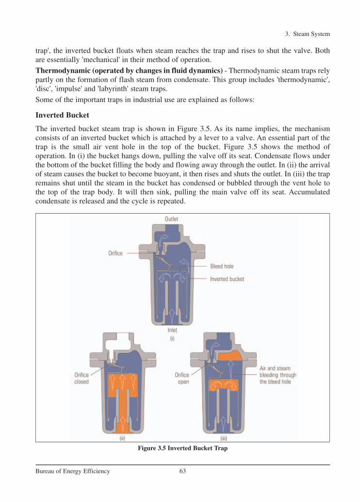
3. Steam System
63Bureau of Energy Efficiency
trap', the inverted bucket floats when steam reaches the trap and rises to shut the valve. Bothare essentially 'mechanical' in their method of operation.
Thermodynamic (operated by changes in fluid dynamics) - Thermodynamic steam traps relypartly on the formation of flash steam from condensate. This group includes 'thermodynamic','disc', 'impulse' and 'labyrinth' steam traps.
Some of the important traps in industrial use are explained as follows:
Inverted Bucket
The inverted bucket steam trap is shown in Figure 3.5. As its name implies, the mechanism consists of an inverted bucket which is attached by a lever to a valve. An essential part of thetrap is the small air vent hole in the top of the bucket. Figure 3.5 shows the method of operation. In (i) the bucket hangs down, pulling the valve off its seat. Condensate flows underthe bottom of the bucket filling the body and flowing away through the outlet. In (ii) the arrivalof steam causes the bucket to become buoyant, it then rises and shuts the outlet. In (iii) the trapremains shut until the steam in the bucket has condensed or bubbled through the vent hole tothe top of the trap body. It will then sink, pulling the main valve off its seat. Accumulated condensate is released and the cycle is repeated.
Figure 3.5 Inverted Bucket Trap
Ch-03.qxd 2/23/2005 11:22 AM Page 63

3. Steam System
64Bureau of Energy Efficiency
In (ii), air reaching the trap at start-up will also give the bucket buoyancy and close thevalve. The bucket vent hole is essential to allow air to escape into the top of the trap foreventual discharge through the main valve seat. The hole, and the pressure differential, aresmall so the trap is relatively slow at venting air. At the same time it must pass (and therefore waste) a certain amount of steam for the trap to operate once the air has cleared.A parallel air vent fitted outside the trap will reduce start-up times.
Advantages of the inverted bucket steam trap
• The inverted bucket steam trap can be made to withstand high pressures.
• Like a float-thermostatic steam trap, it has a good tolerance to waterhammer conditions.
• Can be used on superheated steam lines with the addition of a check valve on the inlet.
• Failure mode is usually open, so it's safer on those applications that require this feature, for example turbine drains.
Disadvantages of the inverted bucket steam trap
• The small size of the hole in the top of the bucket means that this type of trap canonly discharge air very slowly. The hole cannot be enlarged, as steam would passthrough too quickly during normal operation.
• There should always be enough water in the trap body to act as a seal around the lipof the bucket. If the trap loses this water seal, steam can be wasted through the out-let valve. This can often happen on applications where there is a sudden drop insteam pressure, causing some of the condensate in the trap body to 'flash' into steam.The bucket loses its buoyancy and sinks, allowing live steam to pass through the traporifice. Only if sufficient condensate reaches the trap will the water seal form again,and prevent steam wastage.
Float and Thermostatic
The ball float type trap operates by sensing the difference in density between steam and con-densate. In the case of the trap shown in Figure 3.6A, condensate reaching the trap will causethe ball float to rise, lifting the valve off its seat and releasing condensate. As can be seen, thevalve is always flooded and neither steam nor air will pass through it, so early traps of this kindwere vented using a manually operated cock at the top of the body. Modern traps use a ther-mostatic air vent, as shown in Figure 3.6B. This allows the initial air to pass whilst the trap isalso handling condensate.
The automatic air vent uses the same balanced pressure capsule element as a thermostatic steamtrap, and is located in the steam space above the condensate level. After releasing the initial air,it remains closed until air or other non-condensable gases accumulate during normal running and cause it to open by reducing the temperature of the air/steam mixture. The thermostatic air vent offers the added benefit of significantly increasing condensate capacity oncold start-up.
Ch-03.qxd 2/23/2005 11:22 AM Page 64
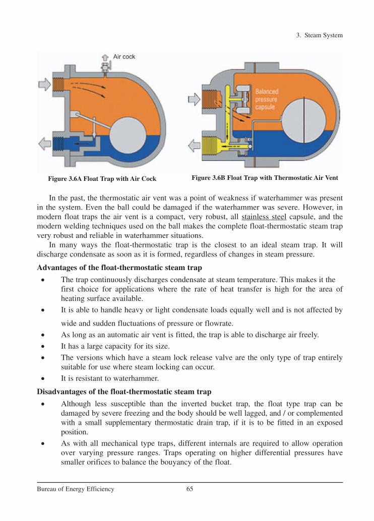
3. Steam System
65Bureau of Energy Efficiency
In the past, the thermostatic air vent was a point of weakness if waterhammer was presentin the system. Even the ball could be damaged if the waterhammer was severe. However, inmodern float traps the air vent is a compact, very robust, all stainless steel capsule, and the modern welding techniques used on the ball makes the complete float-thermostatic steam trapvery robust and reliable in waterhammer situations.
In many ways the float-thermostatic trap is the closest to an ideal steam trap. It will discharge condensate as soon as it is formed, regardless of changes in steam pressure.
Advantages of the float-thermostatic steam trap
• The trap continuously discharges condensate at steam temperature. This makes it the first choice for applications where the rate of heat transfer is high for the area of heating surface available.
• It is able to handle heavy or light condensate loads equally well and is not affected by
wide and sudden fluctuations of pressure or flowrate.
• As long as an automatic air vent is fitted, the trap is able to discharge air freely.
• It has a large capacity for its size.
• The versions which have a steam lock release valve are the only type of trap entirely suitable for use where steam locking can occur.
• It is resistant to waterhammer.
Disadvantages of the float-thermostatic steam trap
• Although less susceptible than the inverted bucket trap, the float type trap can be damaged by severe freezing and the body should be well lagged, and / or complementedwith a small supplementary thermostatic drain trap, if it is to be fitted in an exposed position.
• As with all mechanical type traps, different internals are required to allow operationover varying pressure ranges. Traps operating on higher differential pressures have smaller orifices to balance the bouyancy of the float.
Figure 3.6A Float Trap with Air Cock Figure 3.6B Float Trap with Thermostatic Air Vent
Ch-03.qxd 2/23/2005 11:22 AM Page 65

3. Steam System
66Bureau of Energy Efficiency
Thermodynamic
The thermodynamic trap is an extremely robust steam trap with a simple mode of operation.
The trap operates by means of the dynamic effect of flash steam as it passes through the trap,as depicted in Figure 3.7. The only moving part is the disc above the flat face inside the controlchamber or cap.
On start-up, incoming pressure raises the disc, and cool condensate plus air is immediatelydischarged from the inner ring, under the disc, and out through three peripheral outlets (only 2 shown, Figure 3.7, i)
Hot condensate flowing through the inlet passage into the chamber under the disc drops inpressure and releases flash steam moving at high velocity. This high velocity creates a low pressure area under the disc, drawing it towards its seat (Figure 3.7, ii).
At the same time, the flash steam pressure builds up inside the chamber above the disc, forcing it down against the incoming condensate until it seats on the inner and outer rings. Atthis point, the flash steam is trapped in the upper chamber, and the pressure above the discequals the pressure being applied to the underside of the disc from the inner ring. However, thetop of the disc is subject to a greater force than the underside, as it has a greater surface area.
Eventually the trapped pressure in the upper chamber falls as the flash steam condenses. Thedisc is raised by the now higher condensate pressure and the cycle repeats (Figure 3.7, iv).
Thermostatic
Thermal-element thermostatic traps are temperature actuated. On startup the thermal element isin a contracted position with the valve wide-open, purging condensate, air, and other noncondensable gases. As the system warms up, heat generates pressure in the thermal element,causing it to expand and throttle the flow of hot condensate through the discharge valve.
Figure 3.7 Thermodynamic Trap
Ch-03.qxd 2/23/2005 11:22 AM Page 66
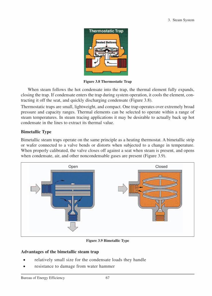
3. Steam System
67Bureau of Energy Efficiency
When steam follows the hot condensate into the trap, the thermal element fully expands,closing the trap. If condensate enters the trap during system operation, it cools the element, con-tracting it off the seat, and quickly discharging condensate (Figure 3.8).
Thermostatic traps are small, lightweight, and compact. One trap operates over extremely broadpressure and capacity ranges. Thermal elements can be selected to operate within a range ofsteam temperatures. In steam tracing applications it may be desirable to actually back up hotcondensate in the lines to extract its thermal value.
Bimetallic Type
Bimetallic steam traps operate on the same principle as a heating thermostat. A bimetallic stripor wafer connected to a valve bends or distorts when subjected to a change in temperature.When properly calibrated, the valve closes off against a seat when steam is present, and openswhen condensate, air, and other noncondensable gases are present (Figure 3.9).
Advantages of the bimetallic steam trap
• relatively small size for the condensate loads they handle
• resistance to damage from water hammer
Figure 3.9 Bimetallic Type
Figure 3.8 Thermostatic Trap
Ch-03.qxd 2/23/2005 11:22 AM Page 67
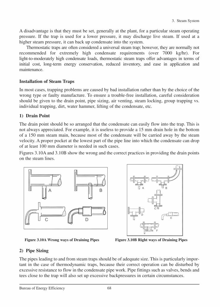
3. Steam System
68Bureau of Energy Efficiency
A disadvantage is that they must be set, generally at the plant, for a particular steam operatingpressure. If the trap is used for a lower pressure, it may discharge live steam. If used at a higher steam pressure, it can back up condensate into the system.
Thermostatic traps are often considered a universal steam trap; however, they are normally notrecommended for extremely high condensate requirements (over 7000 kg/hr). For light-to-moderately high condensate loads, thermostatic steam traps offer advantages in terms of initial cost, long-term energy conservation, reduced inventory, and ease in application and maintenance.
Installation of Steam Traps
In most cases, trapping problems are caused by bad installation rather than by the choice of thewrong type or faulty manufacture. To ensure a trouble-free installation, careful considerationshould be given to the drain point, pipe sizing, air venting, steam locking, group trapping vs.individual trapping, dirt, water hammer, lifting of the condensate, etc.
1) Drain Point
The drain point should be so arranged that the condensate can easily flow into the trap. This isnot always appreciated. For example, it is useless to provide a 15 mm drain hole in the bottomof a 150 mm steam main, because most of the condensate will be carried away by the steamvelocity. A proper pocket at the lowest part of the pipe line into which the condensate can dropof at least 100 mm diameter is needed in such cases.
Figures 3.10A and 3.10B show the wrong and the correct practices in providing the drain pointson the steam lines.
Figure 3.10A Wrong ways of Draining Pipes Figure 3.10B Right ways of Draining Pipes
2) Pipe Sizing
The pipes leading to and from steam traps should be of adequate size. This is particularly impor-tant in the case of thermodynamic traps, because their correct operation can be disturbed byexcessive resistance to flow in the condensate pipe work. Pipe fittings such as valves, bends andtees close to the trap will also set up excessive backpressures in certain circumstances.
Ch-03.qxd 2/23/2005 11:22 AM Page 68

3. Steam System
69Bureau of Energy Efficiency
3) Air Binding
When air is pumped into the trap space by the steam, the trap function ceases. Unless adequateprovision is made for removing air either by way of the steam trap or a separate air vent, theplant may take a long time in warming up and may never give its full output.
4) Steam Locking
This is similar to air binding except that the trap is locked shut by steam instead of air. The typ-ical example is a drying cylinder. It is always advisable to use a float trap provided with a steamlock release arrangement.
5) Group Trapping vs. Individual Trapping
It is tempting to try and save money by connecting several units to a common steam trap asshown in Figure 3.11A. This is known as group trapping. However, it is rarely successful, sinceit normally causes water-logging and loss of output.
The steam consumption of a number of units is never the same at a moment of time andtherefore, the pressure in the various steam spaces will also be different. It follows that the pres-sure at the drain outlet of a heavily loaded unit will be less than in the case of one that is light-ly or properly loaded. Now, if all these units are connected to a common steam trap, the con-densate from the heavily loaded and therefore lower pressure steam space finds it difficult toreach the trap as against the higher pressure condensate produced by lightly or partly loadedunit. The only satisfactory arrangement, thus would be to drain each steam space with own trapand then connect the outlets of the various traps to the common condensate return main asshown in above Figure 3.11B.
6) Dirt
Dirt is the common enemy of steam traps and the causes of many failures. New steam sys-tems contain scale, castings, weld metal, piece of packing and jointing materials, etc. Whenthe system has been in use for a while, the inside of the pipe work and fittings, which isexposed to corrosive condensate can get rusted. Thus, rust in the form of a fine brown powder is also likely to be present. All this dirt will be carried through the system by thesteam and condensate until it reaches the steam trap. Some of it may pass through the trapinto the condensate system without doing any harm, but some dirt will eventually jam the trapmechanism. It is advisable to use a strainer positioned before the steam trap to prevent dirtfrom passing into the system.
Figure 3.11A Group Trapping Figure 3.11B Individual Trapping
Ch-03.qxd 2/23/2005 11:22 AM Page 69

3. Steam System
70Bureau of Energy Efficiency
7) Water Hammer
A water hammer (Figure 3.12) in a steam system is caused by condensate collection in the plantor pipe work picked up by the fast moving steam and carried along with it. When this collection hits obstructions such as bends, valves, steam traps or some other pipe fittings, it islikely to cause severe damage to fittings and equipment and result in leaking pipe joints.
The problem of water hammer can be eliminated by positioning the pipes so that there is a continuous slope in the direction of flow. A slope of at least 12 mm in every 3 metres is necessary, as also an adequate number of drain points every 30 to 50 metres.
8) Lifting the Condensate
It is sometimes necessary to lift condensate from a steam trap to a higher level condensatereturn line (Figure 3.13). The condensate will rise up the lifting pipework when the steam pressure upstream of the trap is higher than the pressure downstream of the trap.
The pressure downstream of the trap is generally called backpressure, and is made up of anypressure existing in the condensate line plus the static lift caused by condensate in the risingpipework. The upstream pressure will vary between start-up conditions, when it is at its lowest,and running conditions, when it is at its highest.
Backpressure is related to lift by using the following approximate conversion: 1 metre liftin pipework = 1m head static pressure or 0.1 bar backpressure.
If a head of 5 m produces a backpressure of 0.5 bar, then this reduces the differential pressure available to push condensate through the trap; although under running conditions the reduction in trap capacity is likely to be significant only where low upstream pressures are used.
In steam mains at start-up, the steam pressure is likely to be very low, and it is common forwater to back-up before the trap, which can lead to waterhammer in the space being drained. To alleviate this problem at start-up, a liquid expansion trap, fitted as shown in Figure 3.13, willdischarge any cold condensate formed at this time to waste.
As the steam main is warmed, the condensate temperature rises, causing the liquid expansion trap to close. At the same time, the steam pressure rises, forcing the hot condensate
Figure 3.12 Water Hammer
Ch-03.qxd 2/23/2005 11:22 AM Page 70
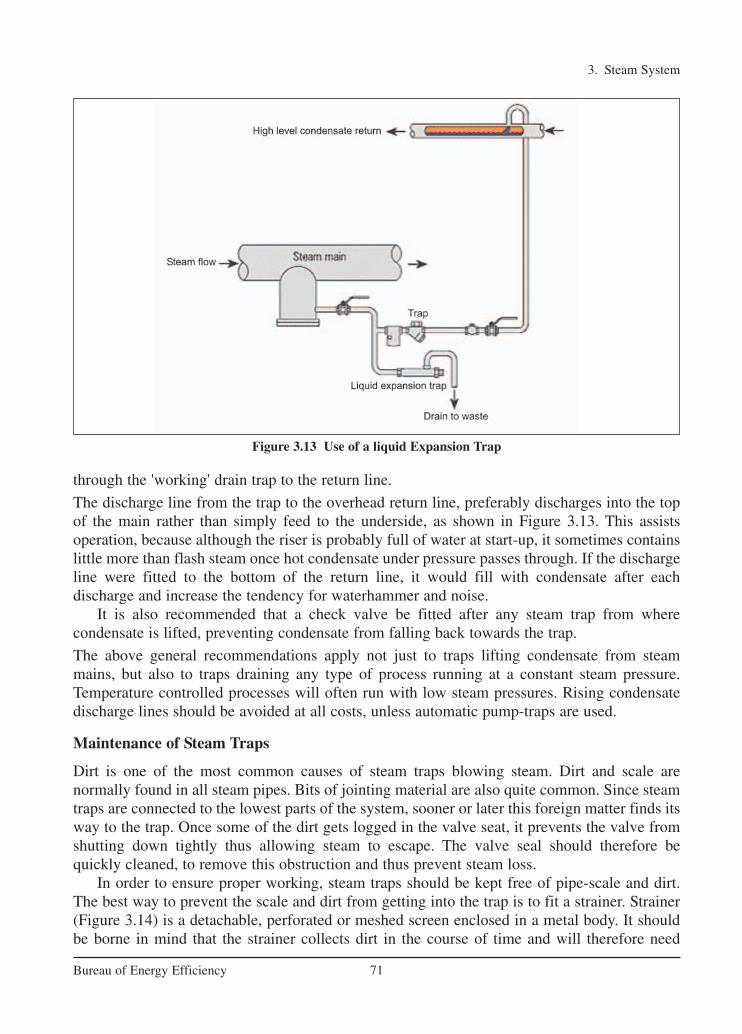
3. Steam System
71Bureau of Energy Efficiency
through the 'working' drain trap to the return line.
The discharge line from the trap to the overhead return line, preferably discharges into the topof the main rather than simply feed to the underside, as shown in Figure 3.13. This assists operation, because although the riser is probably full of water at start-up, it sometimes containslittle more than flash steam once hot condensate under pressure passes through. If the dischargeline were fitted to the bottom of the return line, it would fill with condensate after each discharge and increase the tendency for waterhammer and noise.
It is also recommended that a check valve be fitted after any steam trap from where condensate is lifted, preventing condensate from falling back towards the trap.
The above general recommendations apply not just to traps lifting condensate from steammains, but also to traps draining any type of process running at a constant steam pressure.Temperature controlled processes will often run with low steam pressures. Rising condensatedischarge lines should be avoided at all costs, unless automatic pump-traps are used.
Maintenance of Steam Traps
Dirt is one of the most common causes of steam traps blowing steam. Dirt and scale are normally found in all steam pipes. Bits of jointing material are also quite common. Since steamtraps are connected to the lowest parts of the system, sooner or later this foreign matter finds itsway to the trap. Once some of the dirt gets logged in the valve seat, it prevents the valve fromshutting down tightly thus allowing steam to escape. The valve seal should therefore be quickly cleaned, to remove this obstruction and thus prevent steam loss.
In order to ensure proper working, steam traps should be kept free of pipe-scale and dirt.The best way to prevent the scale and dirt from getting into the trap is to fit a strainer. Strainer(Figure 3.14) is a detachable, perforated or meshed screen enclosed in a metal body. It shouldbe borne in mind that the strainer collects dirt in the course of time and will therefore need
Figure 3.13 Use of a liquid Expansion Trap
Ch-03.qxd 2/23/2005 11:22 AM Page 71

3. Steam System
72Bureau of Energy Efficiency
periodic cleaning. It is of course, much easier to clean a strainer than to overhaul a steam trap.
At this point, we might mention the usefulness of a sight glass fitted just after a steam trap.Sight glasses are useful in ascertaining the proper functioning of traps and in detecting leakingsteam traps. In particular, they are of considerable advantage when a number of steam traps aredischarging into a common return line. If it is suspected that one of the traps is blowing steam,it can be quickly identified by looking through the sight glass.
In most industries, maintenance of steam traps is not a routine job and is neglected unless itleads to some definite trouble in the plant. In view of their importance as steam savers and to monitor plant efficiency, the steam traps require considerably more care than is given.
One may consider a periodic maintenance schedule to repair and replace defective traps in theshortest possible time, preferable during regular maintenance shut downs in preference to breakdown repairs.
Guide to Steam Trap Selection
Actual energy efficiency can be achieved only when
a. Selectionb. Installation andc. Maintenance of steam traps meet the requirements for the purpose it is installed.
Figure 3.14 Strainers
Ch-03.qxd 2/23/2005 11:22 AM Page 72
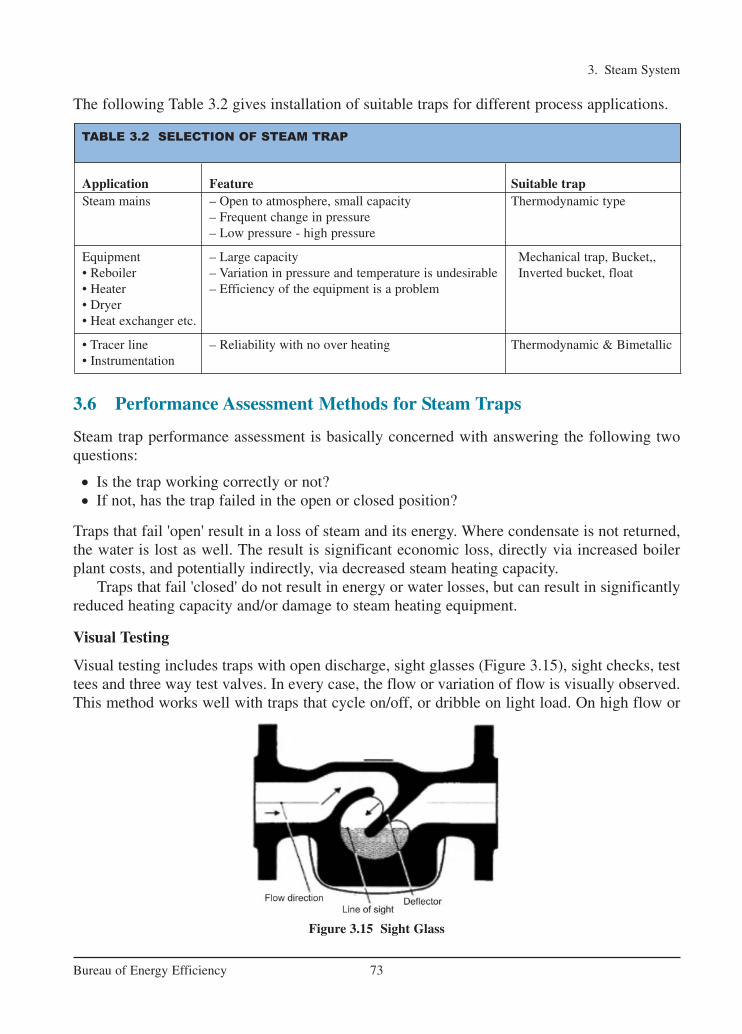
3. Steam System
73Bureau of Energy Efficiency
The following Table 3.2 gives installation of suitable traps for different process applications.
3.6 Performance Assessment Methods for Steam Traps
Steam trap performance assessment is basically concerned with answering the following twoquestions:
• Is the trap working correctly or not? • If not, has the trap failed in the open or closed position?
Traps that fail 'open' result in a loss of steam and its energy. Where condensate is not returned,the water is lost as well. The result is significant economic loss, directly via increased boilerplant costs, and potentially indirectly, via decreased steam heating capacity.
Traps that fail 'closed' do not result in energy or water losses, but can result in significantlyreduced heating capacity and/or damage to steam heating equipment.
Visual Testing
Visual testing includes traps with open discharge, sight glasses (Figure 3.15), sight checks, testtees and three way test valves. In every case, the flow or variation of flow is visually observed.This method works well with traps that cycle on/off, or dribble on light load. On high flow or
Figure 3.15 Sight Glass
TABLE 3.2 SELECTION OF STEAM TRAP
Application Feature Suitable trapSteam mains – Open to atmosphere, small capacity Thermodynamic type
– Frequent change in pressure– Low pressure - high pressure
Equipment – Large capacity Mechanical trap, Bucket,, • Reboiler – Variation in pressure and temperature is undesirable Inverted bucket, float• Heater – Efficiency of the equipment is a problem• Dryer• Heat exchanger etc.
• Tracer line – Reliability with no over heating Thermodynamic & Bimetallic• Instrumentation
Ch-03.qxd 2/23/2005 11:22 AM Page 73
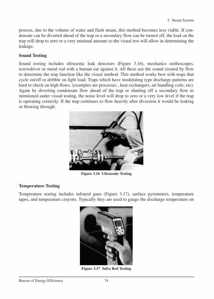
3. Steam System
74Bureau of Energy Efficiency
process, due to the volume of water and flash steam, this method becomes less viable. If con-densate can be diverted ahead of the trap or a secondary flow can be turned off, the load on thetrap will drop to zero or a very minimal amount so the visual test will allow in determining theleakage.
Sound Testing
Sound testing includes ultrasonic leak detectors (Figure 3.16), mechanics stethoscopes, screwdriver or metal rod with a human ear against it. All these use the sound created by flowto determine the trap function like the visual method. This method works best with traps thatcycle on/off or dribble on light load. Traps which have modulating type discharge patterns arehard to check on high flows. (examples are processes , heat exchangers, air handling coils, etc).Again by diverting condensate flow ahead of the trap or shutting off a secondary flow as mentioned under visual testing, the noise level will drop to zero or a very low level if the trapis operating correctly. If the trap continues to flow heavily after diversion it would be leakingor blowing through.
Temperature Testing
Temperature testing includes infrared guns (Figure 3.17), surface pyrometers, temperaturetapes, and temperature crayons. Typically they are used to gauge the discharge temperature on
Figure 3.16 Ultrasonic Testing
Figure 3.17 Infra Red Testing
Ch-03.qxd 2/23/2005 11:22 AM Page 74

3. Steam System
75Bureau of Energy Efficiency
the outlet side of the trap. In the case of temperature tapes or crayon, they are set for a predetermined temperature and they indicate when temperature exceeds that level. Infraredguns and surface pyrometer can detect temperatures on both sides of the trap. Both the infraredand surface pyrometers require bare pipe and a clean surface to achieve a reasonable reading.The temperature reading will typically be lower than actual internal pipe temperature due to thefact that steel does have some heat flow resistance. Scale on the inside of the pipe can also effectthe heat transfer. Some of the more expensive infrared guns can compensate for wall thicknessand material differences. Blocked or turned off traps can easily be detected by infrared guns andsurface pyrometers, as they will show low or cold temperatures. They could also pick up trapswhich may be undersized or backing up large amounts of condensate by detecting low temper-ature readings.
3.7 Energy Saving Opportunities
1. Monitoring Steam Traps
For testing a steam trap, there should be an isolating valve provided in the downstream of thetrap and a test valve shall be provided in the trap discharge. When the test valve is opened, thefollowing points have to be observed:
Condensate discharge––Inverted bucket and thermodynamic disc traps should have intermittent condensate discharge. Float and thermostatic traps should have a continuous condensate discharge. Thermostatic traps can have either continuous or intermittent dischargedepending upon the load. If inverted bucket traps are used for extremely small load, it will havea continuous condensate discharge.
Flash steam––This shall not be mistaken for a steam leak through the trap. The users sometimes get confused between a flash steam and leaking steam. The flash steam and the leaking steam can be approximately identified as follows:• If steam blows out continuously in a blue stream, it is a leaking steam.• If a steam floats out intermittently in a whitish cloud, it is a flash steam.
2. Continuous steam blow and no flow indicate, there is a problem in the trap
Whenever a trap fails to operate and the reasons are not readily apparent, the discharge fromthe trap should be observed. A step-by-step analysis has to be carried out mainly with reference to lack of discharge from the trap, steam loss, continuous flow, sluggish heating,to find out whether it is a system problem or the mechanical problem in the steam trap.
3. Avoiding Steam Leakages
Steam leakage is a visible indicator of waste and must be avoided. It has been estimated that a3 mm diameter hole on a pipeline carrying 7 kg/cm2 steam would waste 33 KL of fuel oil peryear. Steam leaks on high-pressure mains are prohibitively costlier than on low pressure mains.Any steam leakage must be quickly attended to. In fact, the plant should consider a regular surveillance programme for identifying leaks at pipelines, valves, flanges and joints. Indeed, byplugging all leakages, one may be surprised at the extent of fuel savings, which may reach up
Ch-03.qxd 2/23/2005 11:22 AM Page 75

to 5% of the steam consumption in a small or medium scale industry or even higher in installations having several process departments.
To avoid leaks it may be worthwhile considering replacement of the flanged joints which arerarely opened in old plants by welded joints. Figure 3.18 provides a quick estimate for steamleakage based on plume length.
Example• Plume Length = 700 mm• Steam loss = 10 kg/h
4. Providing Dry Steam for Process
The best steam for industrial process heating is the dry saturated steam. Wet steam reduces totalheat in the steam. Also water forms a wet film on heat transfer and overloads traps and condensate equipment. Super heated steam is not desirable for process heating because it givesup heat at a rate slower than the condensation heat transfer of saturated steam.
It must be remembered that a boiler without a superheater cannot deliver perfectly dry saturated steam. At best, it can deliver only 95% dry steam. The dryness fraction of steamdepends on various factors, such as the level of water to be a part of the steam. Indeed, even assimple a thing as improper boiler water treatment can become a cause for wet steam.
As steam flows through the pipelines, it undergoes progressive condensation due to the loss of heat to the colder surroundings, The extent of the condensation depends on the effectiveness of the lagging. For example, with poor lagging, the steam can become excessively wet.
Since dry saturated steam is required for process equipment, due attention must be paid tothe boiler operation and lagging of the pipelines.
Wet steam can reduce plant productivity and product quality, and can cause damage to mostitems of plant and equipment. Whilst careful drainage and trapping can remove most of thewater, it will not deal with the water droplets suspended in the steam. To remove these suspended water droplets, separators are installed in steam pipelines.
3. Steam System
76Bureau of Energy Efficiency
Figure 3.18 Steam Loss vs. Plume Length
Ch-03.qxd 2/23/2005 11:22 AM Page 76
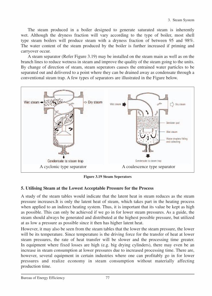
The steam produced in a boiler designed to generate saturated steam is inherently wet. Although the dryness fraction will vary according to the type of boiler, most shell type steam boilers will produce steam with a dryness fraction of between 95 and 98%. The water content of the steam produced by the boiler is further increased if priming and carryover occur.
A steam separator (Refer Figure 3.19) may be installed on the steam main as well as on thebranch lines to reduce wetness in steam and improve the quality of the steam going to the units.By change of direction of steam, steam seperators causes the entrained water particles to be separated out and delivered to a point where they can be drained away as condensate through aconventional steam trap. A few types of separators are illustrated in the Figure below.
5. Utilising Steam at the Lowest Acceptable Pressure for the Process
A study of the steam tables would indicate that the latent heat in steam reduces as the steampressure increases.It is only the latent heat of steam, which takes part in the heating processwhen applied to an indirect heating system. Thus, it is important that its value be kept as highas possible. This can only be achieved if we go in for lower steam pressures. As a guide, thesteam should always be generated and distributed at the highest possible pressure, but utilizedat as low a pressure as possible since it then has higher latent heat.However, it may also be seen from the steam tables that the lower the steam pressure, the lowerwill be its temperature. Since temperature is the driving force for the transfer of heat at lowersteam pressures, the rate of heat transfer will be slower and the processing time greater. In equipment where fixed losses are high (e.g. big drying cylinders), there may even be anincrease in steam consumption at lower pressures due to increased processing time. There are,however, several equipment in certain industries where one can profitably go in for lower pressures and realize economy in steam consumption without materially affecting production time.
3. Steam System
77Bureau of Energy Efficiency
Figure 3.19 Steam Seperators
A cyclonic type separator A coalescence type separator
Ch-03.qxd 2/23/2005 11:22 AM Page 77

Therefore, there is a limit to the reduction of steam pressure. Depending on the equipmentdesign, the lowest possible steam pressure with which the equipment can work should be selected without sacrificing either on production time or on steam consumption.
6. Proper Utilization of Directly Injected Steam
The heating of a liquid by direct injection of steam is often desirable. The equipment requiredis relatively simple, cheap and easy to maintain. No condensate recovery system is necessary.The heating is quick, and the sensible heat of the steam is also used up along with the latentheat, making the process thermally efficient. In processes where dilution is not a problem, heating is done by blowing steam into the liquid (i.e.) direct steam injection is applied. If thedilution of the tank contents and agitation are not acceptable in the process (i.e.)direct steamagitation are not acceptable, indirect steam heating is the only answer.
Ideally, the injected steam should be condensed completely as the bubbles rise through the liquid. This is possible only if the inlet steam pressures are kept very low-around 0.5 kg/cm2
-and certainly not exceeding 1kg/cm2. If pressures are high, the velocity of the steam bubbles will also be high and they will not get sufficient time to condense before they reach thesurface. Figure 3.20 shows a recommended arrangement for direct injection of steam.
A large number of small diameter holes (2 to 5 mm), facing downwards, should be drilled onthe separate pipe. This will help in dissipating the velocity of bubbles in the liquid. A thermo-static control of steam admitted is highly desirable.
7. Minimising Heat Transfer Barriers
The metal wall may not be the only barrier in a heat transfer process. There is likely to be a filmof air, condensate and scale on the steam side. On the product side there may also be baked-onproduct or scale, and a stagnant film of product.
Agitation of the product may eliminate the effect of the stagnant film, whilst regular cleaningon the product side should reduce the scale.
3. Steam System
78Bureau of Energy Efficiency
Figure 3.20 Recommended Arrangement for Directly Injected Steam
Ch-03.qxd 2/23/2005 11:22 AM Page 78
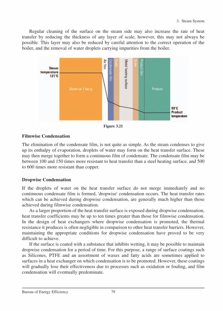
Regular cleaning of the surface on the steam side may also increase the rate of heat transfer by reducing the thickness of any layer of scale, however, this may not always be possible. This layer may also be reduced by careful attention to the correct operation of the boiler, and the removal of water droplets carrying impurities from the boiler.
Filmwise Condensation
The elimination of the condensate film, is not quite as simple. As the steam condenses to giveup its enthalpy of evaporation, droplets of water may form on the heat transfer surface. Thesemay then merge together to form a continuous film of condensate. The condensate film may bebetween 100 and 150 times more resistant to heat transfer than a steel heating surface, and 500to 600 times more resistant than copper.
Dropwise Condensation
If the droplets of water on the heat transfer surface do not merge immediately and no continuous condensate film is formed, 'dropwise' condensation occurs. The heat transfer rateswhich can be achieved during dropwise condensation, are generally much higher than thoseachieved during filmwise condensation.
As a larger proportion of the heat transfer surface is exposed during dropwise condensation,heat transfer coefficients may be up to ten times greater than those for filmwise condensation.In the design of heat exchangers where dropwise condensation is promoted, the thermal resistance it produces is often negligible in comparison to other heat transfer barriers. However,maintaining the appropriate conditions for dropwise condensation have proved to be very difficult to achieve.
If the surface is coated with a substance that inhibits wetting, it may be possible to maintaindropwise condensation for a period of time. For this purpose, a range of surface coatings suchas Silicones, PTFE and an assortment of waxes and fatty acids are sometimes applied to surfaces in a heat exchanger on which condensation is to be promoted. However, these coatingswill gradually lose their effectiveness due to processes such as oxidation or fouling, and filmcondensation will eventually predominate.
3. Steam System
79Bureau of Energy Efficiency
Figure 3.21
Ch-03.qxd 2/23/2005 11:22 AM Page 79

As air is such a good insulator, it provides even more resistance to heat transfer. Air may bebetween 1500 and 3000 times more resistant to heat flow than steel, and 8000 to 16000 moreresistant than copper. This means that a film of air only 0.025 mm thick may resist as much heattransfer as a wall of copper 400 mm thick! Of course all of these comparative relationshipsdepend on the temperature profiles across each layer.
Figure 3.21 illustrates the effect this combination of layers has on the heat transfer process.These barriers to heat transfer not only increase the thickness of the entire conductive layer, butalso greatly reduce the mean thermal conductivity of the layer.
The more resistant the layer to heat flow, the larger the temperature gradient is likely to be.This means that to achieve the same desired product temperature, the steam pressure may needto be significantly higher.
The presence of air and water films on the heat transfer surfaces of either process or space heating applications is not unusual. It occurs in all steam heated process units to somedegree.
To achieve the desired product output and minimise the cost of process steam operations, a high heating performance may be maintained by reducing the thickness of the films on the condensing surface. In practice, air will usually have the most significant effect on heat transfer efficiency, and its removal from the supply steam will increase heating performance.
8. Proper Air Venting
When steam is first admitted to a pipe after a period of shutdown, the pipe is full of air. Furtheramounts of air and other non-condensable gases will enter with the steam, although the proportions of these gases are normally very small compared with the steam. When the steamcondenses, these gases will accumulate in pipes and heat exchangers. Precautions should betaken to discharge them. The consequence of not removing air is a lengthy warming up period,and a reduction in plant efficiency and process performance.
Air in a steam system will also affect the system temperature. Air will exert its own pressure within the system, and will be added to the pressure of the steam to give a total pres-sure. Therefore, the actual steam pressure and temperature of the steam/air mixture will belower than that suggested by a pressure gauge.
Of more importance is the effect air has upon heat transfer. A layer of air only 1 mm thickcan offer the same resistance to heat as a layer of water 25 µm thick, a layer of iron 2 mm thickor a layer of copper 15 mm thick. It is very important therefore to remove air from any steamsystem.
Automatic air vents for steam systems (which operate on the same principle as thermostaticsteam traps) should be fitted above the condensate level so that only air or steam/air mixtures canreach them. The best location for them is at the end of the steam mains as shown in Figure 3.22.
The discharge from an air vent must be piped to a safe place. In practice, a condensate linefalling towards a vented receiver can accept the discharge from an air vent.
In addition to air venting at the end of a main, air vents should also be fitted:
• In parallel with an inverted bucket trap or, in some instances, a thermodynamic trap. These traps are sometimes slow to vent air on start-up.
3. Steam System
80Bureau of Energy Efficiency
Ch-03.qxd 2/23/2005 11:22 AM Page 80

• In awkward steam spaces (such as at the opposite side to where steam enters a jacketed pan).
• Where there is a large steam space (such as an autoclave), and a steam/air mixture could affect the process quality.
9. Condensate Recovery
The steam condenses after giving off its latent heat in the heating coil or the jacket of theprocess equipment. A sizable portion (about 25%) of the total heat in the steam leaves theprocess equipment as hot water. Figure 3.23 compares the amount of energy in a kilogram ofsteam and condensate at the same pressure. The percentage of energy in condensate to that in
3. Steam System
81Bureau of Energy Efficiency
Figure 3.22 Draining and Venting at the End of a Steam Main
Figure 3.23 Heat Content of Steam and Condensate at the Same Pressure
Ch-03.qxd 2/23/2005 11:22 AM Page 81

steam can vary from 18% at 1 bar g to 30% at 14 bar g; clearly the liquid condensate is worthreclaiming.
If this water is returned to the boiler house, it will reduce the fuel requirements of the boiler.For every 60°C rise in the feed water temperature, there will be approximately 1% saving offuel in the boiler.
Benefits of Condensate Recovery
Financial reasonsCondensate is a valuable resource and even the recovery of small quantities is often economi-cally justifiable. The discharge from a single steam trap is often worth recovering.
Un-recovered condensate must be replaced in the boiler house by cold make-up water withadditional costs of water treatment and fuel to heat the water from a lower temperature.
Water chargesAny condensate not returned needs to be replaced by make-up water, incurring further watercharges from the local water supplier.
Effluent restrictionsHigh temperature of effluent is detrimental to the environment and may damage to pipes.Condensate above this temperature must be cooled before it is discharged, which may incurextra energy costs.
Maximising boiler outputColder boiler feedwater will reduce the steaming rate of the boiler. The lower the feedwatertemperature, the more heat, and thus fuel needed to heat the water.
Boiler feedwater qualityCondensate is distilled water, which contains almost no total dissolved solids (TDS). Boilersneed to be blown down to reduce their concentration of dissolved solids in the boiler water.Returning more condensate to the feedtank reduces the need for blowdown and thus reduces theenergy lost from the boiler.
Summary of reasons for condensate recovery:
• Water charges are reduced.
• Effluent charges and possible cooling costs are reduced.
• Fuel costs are reduced.
• More steam can be produced from the boiler.
• Boiler blowdown is reduced - less energy is lost from the boiler.
• Chemical treatment of raw make-up water is reduced.
3. Steam System
82Bureau of Energy Efficiency
Ch-03.qxd 2/23/2005 11:22 AM Page 82

10. Insulation of Steam Pipelines and Hot Process Equipments
Heat can be lost due to radiation from steam pipes. As an example while lagging steam pipes,it is common to see leaving flanges uncovered. An uncovered flange is equivalent to leaving 0.6metre of pipe line unlagged. If a 0.15 m steam pipe diameter has 5 uncovered flanges, therewould be a loss of heat equivalent to wasting 5 tons of coal or 3000 litres of oil a year. This isusually done to facilitate checking the condition of flange but at the cost of considerable heatloss. The remedy is to provide easily detachable insulation covers, which can be easily removedwhen necessary. The various insulating materials used are cork, Glass wool, Rock wool andAsbestos.
The following table 3.3 indicates the heat loss from a hot uninsulated surface to the environment:
This is based on 35°C ambient temperature, 0.9 emissivity factor and still wind conditions. The effective insulation of a steam system can bring down the heat losses to less than 75kCal/m2/h
Note: Calculation procedure to find out the economic thickness of insulation is given in chapter-5: Insulation and Refractories.
Case Study to elaborate the effect of insulation of flanges: 100 ft of 6 Inch pipe 12 Flanges of6 Inch = 5 ft of pipe length Heat loss in following 2 cases:
Case (I) - Bare pipe Case (II) - Pipe with 2 inch insulation aluminum cladding
3. Steam System
83Bureau of Energy Efficiency
TABLE 3.3 QUANTITY OF HEAT LOST AT
DIFFERENT TEMPERATURES
Difference in temperature Heat lossbetween ambient & surface
(oC) (kCal/m2 /h)
50 500
100 1350
200 3790
400 13640
Parameter Unit Case (I) Case (II)
Heat Loss kCal/year 36,300 4,100
Steam Loss kg/Year/100ft 68 3.2
Fuel Loss kg/Year/100ft 55 0.26
Energy Saving Potential Rs. Per Year/100 ft 60 2.8
Ch-03.qxd 2/23/2005 11:22 AM Page 83

11. Flash Steam Recovery
Flash steam is produced when condensate at a high pressure is released to a lower pressure andcan be used for low pressure heating.
The higher the steam pressure and lower the flash steam pressure the greater the quantity offlash steam that can be generated. In many cases, flash steam from high pressure equipments ismade use of directly on the low pressure equipments to reduce use of steam through pressurereducing valves.
The flash steam quantity can be calculated by the following formula with the help of a steam table:
Where: S1 is the sensible heat of higher pressure condensate.
S2 is the sensible heat of the steam at lower pressure (at which it has been flashed).
L2 is the latent heat of flash steam (at lower pressure).
Example: Calculating the amount of flash steam from condensate
Hot condensate at 7 bar g has a heat content of about 721 kJ/kg. When it is released to atmospheric pressure (0 bar g), each kilogram of water can only retain about 419 kJ of heat. Theexcess energy in each kilogram of the condensate is therefore 721 – 419 = 302 kJ. This excessenergy is available to evaporate some of the condensate into steam, the amount evaporatedbeing determined by the proportion of excess heat to the amount of heat required to evaporatewater at the lower pressure, which in this example, is the enthalpy of evaporation at atmosphericpressure, 2258 kJ/kg.
Example: Proportion of flash steam using Figure 3.24:
Pressure on the trap = 4 bar g
Flash steam pressure = 0 bar g
% Flash steam = 10%
The amount of flash steam in the pipe is the most important factor when sizing trap dischargelines.
3. Steam System
84Bureau of Energy Efficiency
1 2
2
S –SFlash steam available % =
L
Ch-03.qxd 2/23/2005 11:22 AM Page 84

Flash steam can be used on low pressure applications like direct injection and can replace anequal quantity of live steam that would be otherwise required. The demand for flash steamshould exceed its supply, so that there is no build up of pressure in the flash vessel and the consequent loss of steam through the safety valve. Generally, the simplest method of using flashsteam is to flash from a machine/equipment at a higher pressure to a machine/equipment at alower pressure, thereby augmenting steam supply to the low pressure equipment.
In general, a flash system should run at the lowest possible pressure so that the maximumamount of flash is available and the backpressure on the high pressure systems is kept as lowas possible.
Flash steam from the condensate can be separated in an equipment called the 'flash vessel'.This is a vertical vessel as shown in the Figure 3.25. The diameter of the vessel is such that aconsiderable drop in velocity allows the condensate to fall to the bottom of the vessel fromwhere it is drained out by a steam trap preferably a float trap. Flash steam itself rises to leave
3. Steam System
85Bureau of Energy Efficiency
Figure 3.24 Quantity of Flash Steam Graph
Figure 3.25 Flash Steam Recovery
Ch-03.qxd 2/23/2005 11:22 AM Page 85

the vessel at the top. The height of the vessel should be sufficient enough to avoid water beingcarried over in the flash steam.
The condensate from the traps (A) along with some flash steam generated passes throughvessel (B). The flash steam is let out through (C) and the residual condensate from (B) goes outthrough the steam trap (D). The flash vessel is usually fitted with a 'pressure gauge' to know thequality of flash steam leaving the vessel. A 'safety valve' is also provided to vent out the steamin case of high pressure build up in the vessel.
12. Reducing the Work to be done by Steam
The equipments should be supplied with steam as dry as possible. The plant should be madeefficient. For example, if any product is to be dried such as in a laundry, a press could be usedto squeeze as much water as possible before being heated up in a dryer using steam.
Therefore, to take care of the above factors, automatic draining is essential and can beachieved by steam traps. The trap must drain condensate, to avoid water hammer, thermal shockand reduction in heat transfer area. The trap should also evacuate air and other non-condensablegases, as they reduce the heat transfer efficiency and also corrode the equipment. Thus, a steamtrap is an automatic valve that permits passage of condensate, air and other non-condensablegases from steam mains and steam using equipment, while preventing the loss of steam in thedistribution system or equipment.
The energy saving is affected by following measures:
• Reduction in operating hours
• Reduction in steam quantity required per hour
• Use of more efficient technology
• Minimizing wastage.
When the steam reaches the place where its heat is required, it must be ensured that the steamhas no more work to do than is absolutely necessary. Air-heater batteries, for example, whichprovide hot air for drying, will use the same amount of steam whether the plant is fully or partly loaded. So, if the plant is running only at 50 percent load, it is wasting twice as muchsteam (or twice as much fuel) than necessary.
3. Steam System
86Bureau of Energy Efficiency
Figure 3.26 Steam Wastage Due to Insufficient Mechanical Drying
Ch-03.qxd 2/23/2005 11:22 AM Page 86

Always use the most economical way to removing the bulk of water from the wet material.Steam can then be used to complete the process. For this reason, hydro-extractors, spin dryers,squeeze or calendar rolls, presses, etc. are initially used in many drying processes to remove themass of water. The efficiency with which this operation is carried out is most important. Forexample, in a laundry for finishing sheets (100 kg/hr. dry weight), the normal moisture contentof the sheets as they leave the hydroextractor, is 48% by weight.
Thus, the steam heated iron has to evaporate nearly 48 kg of water. This requires 62 kg ofsteam. If, due to inefficient drying in the hydro-extractor, the steam arrive at the iron with 52%moisture content i.e. 52 kg of water has to be evaporated, requiring about 67 kg of steam. So,for the same quantity of finished product, the steam consumption increases by 8 per cent. Thisis illustrated in Figure 3.26.
3. Steam System
87Bureau of Energy Efficiency
QUESTIONS
1. Latent heat of steam at lower pressure is lower - True / False?
2. Name two reasons why steam is used as a heat transfer medium?
3. The heat which is required to change the phase from water at 100°C to saturatedsteam is called a) Latent Heat b) Sensible Heat c) Super Heat d) Specific Heat
4. The slope for steam piping should bea) 12mm in 3 metres b) 12 inches in 3 feet c) 12m in 3 km d) 3m in 12km
5. The normal velocities encountered in pipes for superheated steam isa) 50–70 m/s b) 30–40 m/s c) 20–25 m/s d) 15–20 m/s
6. Name two functions of a steam trap?
7. The major cause for steam trap blowing steam isa) dirt b) too much condensate c) too much steam d) too much air
8. Ideal trap for steam mains isa) thermodynamic b) float c) inverted bucket d) bimetallic
9. Name two cases when steam trap can fail?
10. Name a few methods for testing of steam traps?
11. How do you distinguish between flash steam and live steam?
12. The best quality of steam for industrial process heating isa) Dry saturated b) Super heated c) Wet Steam d) High pressure steam
13. Explain why low-pressure steam is more efficient?
14. What are the precautions to be taken while steam pressure is reduced for a process?
15. Discuss the advantages of direct injection versus indirect injection using steam?
16. List a few barriers to heat transfer in heat exchangers using steam?
17. 1% fuel can be saved in the boiler fuel consumption, if feed water temperature isincreased by a) 6°C b) 10°C c)12°C d) 22°C
Ch-03.qxd 2/23/2005 11:22 AM Page 87

3. Steam System
88Bureau of Energy Efficiency
REFERENCES
1. Efficient Utilisation of Steam – Energy Efficiency Office, U.K.2. Efficient Use of Steam – Spirax Sarco3. Fundamentals of Steam Boilers & Pressure Vessel Inspection Techniques by Homi P.
Seervai, Macmillan Company of India Ltd, New Delhi, 1974.4. Industrial Energy Conservation by Melvin H.Chiogioji, Marcel Dekker Inc, 1979, New
York. 5. Industrial Heat Generation and Distribution -NIFES Training Manual Issued For
CEC - India Energy Bus Project6. The Efficient Use of Steam by Oliver Lyle, Her Majesty Stationery Office, London, 1947.7. Steam Generation by J.N.Williams, George Allen And Unwin Ltd, London, 1969.8. Improving Steam System Performance a source book for industry by Office of Industrial
Technologies, Energy Efficiency and Renewable Energy, US Department of Energy
www.iclei.org
www.pcra.org
www.armstrong-intl.com
www.energy-efficiency.gov.uk
www.actionenergy.org.uk
www.engineeringtoolbox.com
18. Lagging of steam pipes is done to preventa) Heat loss b) Steam leaks c) High pressures d) Pipe damages
19. Give an example of: Energy savings by reducing the work done by steam
Ch-03.qxd 2/23/2005 11:22 AM Page 88

4 FURNACES
89Bureau of Energy Efficiency
Syllabus
Furnaces: Classification, General fuel economy measures in furnaces, Excess air, Heat
distribution, Temperature control, Draft control, Waste heat recovery.
A furnace is an equipment to melt metals for casting or heat materials for change of shape
(rolling, forging etc) or change of properties (heat treatment).
4.1 Types and Classification of Different Furnaces
Based on the method of generating heat, furnaces are broadly classified into two types namely
combustion type (using fuels) and electric type. In case of combustion type furnace, depending
upon the kind of combustion, it can be broadly classified as oil fired, coal fired or gas fired.
• Based on the mode of charging of material furnaces can be classified as (i) Intermittent or
Batch type furnace or Periodical furnace and (ii) Continuous furnace.
• Based on mode of waste heat recovery as recuperative and regenerative furnaces.
• Another type of furnace classification is made based on mode of heat transfer, mode of
charging and mode of heat recovery as shown in the Figure 4.1 below.
Characteristics of an Efficient Furnace
Furnace should be designed so that in a given time, as much of material as possible can be
heated to an uniform temperature as possible with the least possible fuel and labour. To achieve
Furnace
classification
According to
mode of heat
transfer
According to
mode of
charging
According to
mode of heat
recovery
Open fire place furnace
Heated through Medium
Batch
Forging
Re-rolling (Batch /
continuous pusher)
Pot Continuous
Glass tank
melting
(regenerative /
recuperative)
Recuperative
Regenerative
Figure 4.1: Furnace Classification
Ch-04.qxd 2/23/2005 5:22 PM Page 89
this end, the following parameters can be considered.
• Determination of the quantity of heat to be imparted to the material or charge.
• Liberation of sufficient heat within the furnace to heat the stock and overcome all heat
losses.
• Transfer of available part of that heat from the furnace gases to the surface of the heating
stock.
• Equalisation of the temperature within the stock.
• Reduction of heat losses from the furnace to the minimum possible extent.
Furnace Energy Supply
Since the products of flue gases directly contact the stock, type of fuel chosen is of importance.
For example, some materials will not tolerate sulphur in the fuel. Also use of solid fuels will
generate particulate matter, which will interfere the stock place inside the furnace. Hence, vast
majority of the furnaces use liquid fuel, gaseous fuel or electricity as energy input.
Melting furnaces for steel, cast iron use electricity in induction and arc furnaces.
Non-ferrous melting utilizes oil as fuel.
Oil Fired Furnace
Furnace oil is the major fuel used in oil fired furnaces, especially for reheating and heat
treatment of materials. LDO is used in furnaces where presence of sulphur is undesirable. The
key to efficient furnace operation lies in complete combustion of fuel with minimum excess air.
Furnaces operate with efficiencies as low as 7% as against upto 90% achievable in other
combustion equipment such as boiler. This is because of the high temperature at which the furnaces
have to operate to meet the required demand. For example, a furnace heating the stock to 1200°C
will have its exhaust gases leaving atleast at 1200°C resulting in a huge heat loss through the stack.
However, improvements in efficiencies have been brought about by methods such as preheating of
stock, preheating of combustion air and other waste heat recovery systems.
Typical Furnace System
i) Forging Furnaces
The forging furnace is used for preheating billets and ingots to attain a ‘forge’ temperature.
The furnace temperature is maintained at around 1200 to 1250°C. Forging furnaces, use an open
fireplace system and most of the heat is transmitted by radiation. The typical loading in a
forging furnace is 5 to 6 tonnes with the furnace operating for 16 to 18 hours daily. The total
operating cycle can be divided into (i) heat-up time (ii) soaking time and (iii) forging time.
Specific fuel consumption depends upon the type of material and number of ‘reheats’ required.
Rerolling Mill Furnace
a) Batch type
A box type furnace is employed for batch type rerolling mill. The furnace is basically used for
heating up scrap, small ingots and billets weighing 2 to 20 kg. for rerolling. The charging and
discharging of the ‘material’ is done manually and the final product is in the form of rods, strips
etc. The operating temperature is about 1200 oC. The total cycle time can be further
categorized into heat-up time and rerolling time. During heat-up time the material gets heated
4. Furnaces
90Bureau of Energy Efficiency
Ch-04.qxd 2/23/2005 5:22 PM Page 90

upto the required temperature and is removed manually for rerolling. The average output from
these furnaces varies from 10 to 15 tonnes / day and the specific fuel consumption varies from
180 to 280 kg. of coal / tonne of heated material.
b) Continuous Pusher Type:
The process flow and operating cycles of a continuous pusher type is the same as that of the batch
furnace. The operating temperature is about 1250 °C. Generally, these furnaces operate 8 to 10
hours with an output of 20 to 25 tonnes per day. The material or stock recovers a part of the heat in
flue gases as it moves down the length of the furnace. Heat absorption by the material in the
furnace is slow, steady and uniform throughout the cross-section compared with batch type.
iii) Continuous Steel Reheating Furnaces
The main function of a reheating furnace is to raise the temperature of a piece of steel, typically to
between 900°C and 1250oC, until it is plastic enough to be pressed or rolled to the desired section,
size or shape. The furnace must also meet specific requirements and objectives in terms of stock
heating rates for metallurgical and productivity reasons. In continuous reheating, the steel stock
forms a continuous flow of material and is heated to the desired temperature as it travels through
the furnace.
All furnaces possess the features shown in Figure 4.2
• A refractory chamber constructed of insulating materials for retaining heat at the high
operating temperatures.
• A hearth to support or carry the steel. This can consist of refractory materials or an arrange-
ment of metallic supports that may be water-cooled.
• Burners that use liquid or gaseous fuels to raise and maintain the temperature in the cham-
ber. Coal or electricity can be used for reheating. A method of removing the combustion
exhaust gases from the chamber
4. Furnaces
Bureau of Energy Efficiency
Figure 4.2: Furnace Feature
Ch-04.qxd 2/23/2005 5:22 PM Page 91

4. Furnaces
92Bureau of Energy Efficiency
• A method of introducing and removing the steel from the chamber.
• These facilities depend on the size and type of furnace, the shape and size of the steel being
processed, and the general layout of the rolling mill.
• Common systems include roller tables, conveyors, charging machines and furnace
pushers.
Heat Transfer in Furnaces
The main ways in which heat is transferred to the steel in a reheating furnace are shown in
Figure 4.3. In simple terms, heat is transferred to the stock by:
• Radiation from the flame, hot combustion products and the furnace walls and roof.
• Convection due to the movement of hot gases over the stock surface
At the high temperatures employed in reheating furnaces, the dominant mode of heat t
ransfer is wall radiation. Heat transfer by gas radiation is dependent on the gas composition
(mainly the carbon dioxide and water vapour concentrations), the temperature and the
geometry of the furnace.
Types of Continuous Reheating Furnace
Continuous reheating furnaces are primarily categorised by the method by which stock is
transported through the furnace. There are two basic methods:
· Stock is butted together to form a stream of material that is pushed through the furnace. Such
furnaces are called pusher type furnaces.
· Stock is placed on a moving hearth or supporting structure which transports the steel through the
furnace. Such types include walking beam, walking hearth, rotary hearth and continuous
recirculating bogie furnaces.
Figure 4.3 Heat Transfer in Furnace
Ch-04.qxd 2/23/2005 5:22 PM Page 92

The major consideration with respect to furnace energy use is that the inlet and outlet apertures
should be minimal in size and designed to avoid air infiltration.
i) Pusher Type Furnaces
The pusher type furnace is popular in steel industry. It has relatively low installation and
maintenance costs compared to moving hearth furnaces. The furnace may have a solid hearth,
but it is also possible to push the stock along skids with water-cooled supports that allow both
the top and bottom faces of the stock to he heated. The design of a typical pusher furnace design
is shown schematically in Figure 4.4.
Pusher type furnaces, however, do have some disadvantages, including:
• Frequent damage of refractory hearth and skid marks on material
• Water cooling energy losses from the skids and stock supporting structure in top and
• bottom fired furnaces have a detrimental effect on energy use;
• Discharge must be accompanied by charge:
• Stock sizes and weights and furnace length are limited by friction and the possibility of
stock pile-ups.
• All round heating of the stock is not possible.
ii) Walking Hearth Furnaces
The walking hearth furnace (Figure.4.5) allows the stock to be transported through the
furnace in discrete steps. Such furnaces have several attractive features, including: simplicity of
design, ease of construction, ability to cater for different stock sizes (within limits), negligible
water cooling energy losses and minimal physical marking of the stock.
The main disadvantage of walking hearth furnaces is that the bottom face of the stock
cannot be heated. This can he alleviated to some extent by maintaining large spaces between
pieces of stock. Small spaces between the individual stock pieces limits the heating of the side
4. Furnaces
93Bureau of Energy Efficiency
Figure 4.4 Pusher Type Furnaces
Ch-04.qxd 2/23/2005 5:22 PM Page 93

faces and increases the potential for unacceptable temperature differences within the stock at
discharge. Consequently, the stock residence time may be long, possibly several hours; this may
have an adverse effect on furnace flexibility and the yield may be affected by scaling.
iii) Rotary Hearth Furnace
The rotary hearth furnace (Figure 4.6) has tended to supersede the recirculating bogie type.
The heating and cooling effects introduced by the bogies are eliminated, so heat storage losses are
4. Furnaces
94Bureau of Energy Efficiency
Figure 4.5 Walking Hearth Type Furnace
Figure 4.6 Rotary Hearth Type Furnace
Ch-04.qxd 2/23/2005 5:22 PM Page 94

less. The rotary hearth has, however a more complex design with an annular shape and revolving
hearth.
iv) Continuous Recirculating Bogie type Furnaces
These types of moving hearth type furnaces tend to be used for compact stock of variable size
and geometry. In bogie furnaces (Figure 4.7), the stock is placed on a bogie with a refractory
hearth, which travels through the furnace with others in the form of a train. The entire furnace
length is always occupied by bogies. Bogie furnaces tend to be long and narrow and to suffer
from problems arising from inadequate sealing of the gap between the bogies and furnace shell,
difficulties in removing scale, and difficulties in firing across a narrow hearth width.
v) Walking Beam Furnaces:
The walking beam furnace (Figure 4.8 overcomes many of the problems of pusher furnaces and
permits heating of the bottom face of the stock. This allows shorter stock heating times and
furnace lengths and thus better control of heating rates, uniform stock discharge temperatures
and operational flexibility. In common with top and bottom fired pusher furnaces, however,
much of the furnace is below the level of the mill; this may be a constraint in some applications.
4. Furnaces
95Bureau of Energy Efficiency
Figure 4.7 Continuous circulating bogie type furnace
Ch-04.qxd 2/23/2005 5:22 PM Page 95
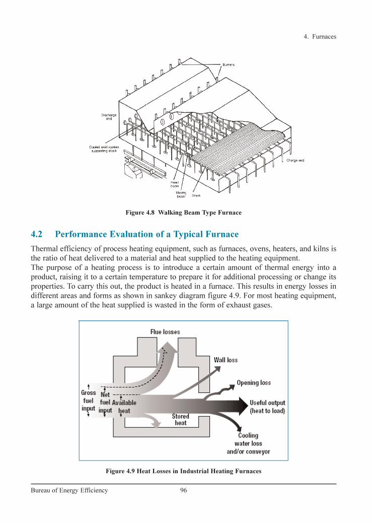
4. Furnaces
96Bureau of Energy Efficiency
Figure 4.8 Walking Beam Type Furnace
Figure 4.9 Heat Losses in Industrial Heating Furnaces
4.2 Performance Evaluation of a Typical Furnace
Thermal efficiency of process heating equipment, such as furnaces, ovens, heaters, and kilns is
the ratio of heat delivered to a material and heat supplied to the heating equipment.
The purpose of a heating process is to introduce a certain amount of thermal energy into a
product, raising it to a certain temperature to prepare it for additional processing or change its
properties. To carry this out, the product is heated in a furnace. This results in energy losses in
different areas and forms as shown in sankey diagram figure 4.9. For most heating equipment,
a large amount of the heat supplied is wasted in the form of exhaust gases.
Ch-04.qxd 2/23/2005 5:22 PM Page 96

4. Furnaces
Material Handling Losses
Many furnaces use equipment to convey the work into and
out of the heating chamber, and this can also lead to heat
losses. Conveyor belts or product hangers that enter the
heating chamber cold and leave it at higher temperatures
drain energy from the combustion gases. In car bottom furnaces, the hot car structure gives off
heat to the room each time it rolls out of the furnace to load or remove work. This lost energy
must be replaced when the car is returned to the furnace.
Cooling Media Losses
Water or air cooling protects rolls, bearings, and doors in hot furnace environments, but at the
cost of lost energy. These components and their cooling media (water, air, etc.) become the con-
duit for additional heat losses from the furnace. Maintaining an adequate flow of cooling media
is essential, but it might be possible to insulate the furnace and load from some of these losses.
These furnace losses include:
• Heat storage in the furnace structure
• Losses from the furnace outside walls or structure
• Heat transported out of the furnace by the load conveyors, fixtures, trays, etc.
• Radiation losses from openings, hot exposed parts, etc.
• Heat carried by the cold air infiltration into the furnace
• Heat carried by the excess air used in the burners.
Stored Heat Loss:
First, the metal structure and insulation of the furnace must be heated so their interior surfaces
are about the same temperature as the product they contain. This stored heat is held in the
structure until the furnace shuts down, then it leaks out into the surrounding area. The more
frequently the furnace is cycled from cold to hot and back to cold again, the more frequently
this stored heat must be replaced. Fuel is consumed with no useful output.
Wall losses:
Additional heat losses take place while the furnace is in
production. Wall or transmission losses are caused by the
conduction of heat through the walls, roof, and floor of the
heating device, as shown in Figure 4.10. Once that heat
reaches the outer skin of the furnace and radiates to the
surrounding area or is carried away by air currents, it must
be replaced by an equal amount taken from the combus-
tion gases. This process continues as long as the furnace is
at an elevated temperature.
97Bureau of Energy Efficiency
Figure 4.10 Wall Losses
Ch-04.qxd 2/23/2005 5:22 PM Page 97
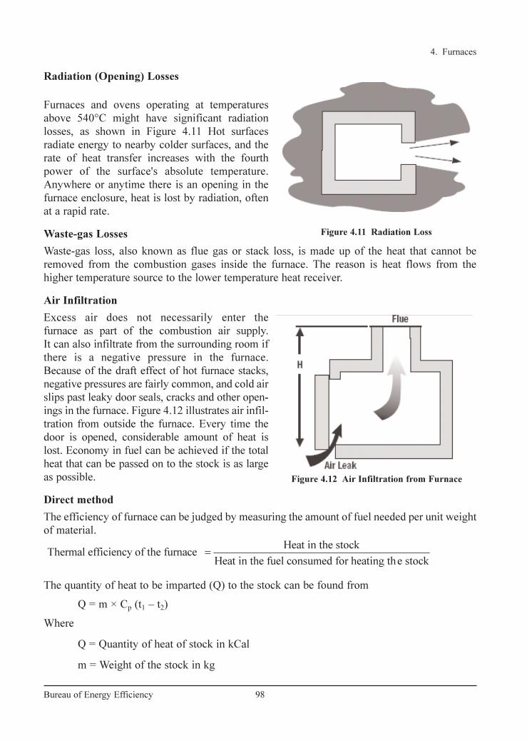
4. Furnaces
98Bureau of Energy Efficiency
Radiation (Opening) Losses
Furnaces and ovens operating at temperatures
above 540°C might have significant radiation
losses, as shown in Figure 4.11 Hot surfaces
radiate energy to nearby colder surfaces, and the
rate of heat transfer increases with the fourth
power of the surface's absolute temperature.
Anywhere or anytime there is an opening in the
furnace enclosure, heat is lost by radiation, often
at a rapid rate.
Waste-gas Losses
Waste-gas loss, also known as flue gas or stack loss, is made up of the heat that cannot be
removed from the combustion gases inside the furnace. The reason is heat flows from the
higher temperature source to the lower temperature heat receiver.
Air Infiltration
Excess air does not necessarily enter the
furnace as part of the combustion air supply.
It can also infiltrate from the surrounding room if
there is a negative pressure in the furnace.
Because of the draft effect of hot furnace stacks,
negative pressures are fairly common, and cold air
slips past leaky door seals, cracks and other open-
ings in the furnace. Figure 4.12 illustrates air infil-
tration from outside the furnace. Every time the
door is opened, considerable amount of heat is
lost. Economy in fuel can be achieved if the total
heat that can be passed on to the stock is as large
as possible.
Direct method
The efficiency of furnace can be judged by measuring the amount of fuel needed per unit weight
of material.
The quantity of heat to be imparted (Q) to the stock can be found from
Q = m × Cp (t1 – t2)
Where
Q = Quantity of heat of stock in kCal
m = Weight of the stock in kg
Heat in the stockThermal efficiency of the furnace
Heat in the fuel consumed for heating the stock=
Figure 4.11 Radiation Loss
Figure 4.12 Air Infiltration from Furnace
Ch-04.qxd 2/23/2005 5:22 PM Page 98

Cp = Mean specific heat of stock in kCal/kg°C
t1 = Final temperature of stock desired, °C
t2 = Initial temperature of the stock before it enters the furnace, °C
Indirect Method
Similar to the method of evaluating boiler efficiency by direct method, furnace efficiency can also be
calculated by indirect methods. Furnace efficiency is calculated after subtracting sensible heat loss in
flue gas, loss due to moisture in flue gas, heat loss due to openings in furnace, heat loss through
furnace skin and other unaccounted losses.
In order to find out furnace efficiency using indirect method, various parameters that are required
are hourly furnace oil consumption, material output, excess air quantity, temperature of flue gas,
temperature of furnace at various zones, skin temperature and hot combustion air temperature.
Instruments like infrared thermometer, fuel efficiency monitor, surface thermocouple and other
measuring devices are required to measure the above parameters.
Typical thermal efficiencies for common industrial furnaces are given in Table: 4.1
Example: Furnace Efficiency Calculation for a Typical Reheating Furnace
An oil-fired reheating furnace has an operating temperature of around 1340°C. Average fuel
consumption is 400 litres/hour. The flue gas exit temperature is 750 °C after air preheater.
Air is preheated from ambient temperature of 40 °C to 190 °C through an air pre-heater.
4. Furnaces
99Bureau of Energy Efficiency
Furnace Type Typical thermal efficiencies (%)
1) Low Temperature furnaces
a. 540–980 oC (Batch type) 20–30
b. 540–980 oC (Continous type) 15–25
c. Coil Anneal (Bell) radiant type 5–7
d. Strip Anneal Muffle 7–12
2) High temperature furnaces
a. Pusher, Rotary 7–15
b. Batch forge 5–10
3) Continuous Kiln
a. Hoffman 25–90
b. Tunnel 20–80
4) Ovens
a. Indirect fired ovens (20°C–370°C) 35–40
b. Direct fired ovens (20°C–370°C) 35–40
TABLE 4.1 THERMAL EFFICIENCIES FOR COMMON INDUSTRIAL
FURNACES
Ch-04.qxd 2/23/2005 5:22 PM Page 99
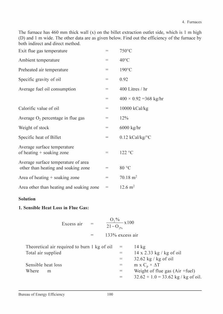
The furnace has 460 mm thick wall (x) on the billet extraction outlet side, which is 1 m high
(D) and 1 m wide. The other data are as given below. Find out the efficiency of the furnace by
both indirect and direct method.
Exit flue gas temperature = 750°C
Ambient temperature = 40°C
Preheated air temperature = 190°C
Specific gravity of oil = 0.92
Average fuel oil consumption = 400 Litres / hr
= 400 × 0.92 =368 kg/hr
Calorific value of oil = 10000 kCal/kg
Average O2 percentage in flue gas = 12%
Weight of stock = 6000 kg/hr
Specific heat of Billet = 0.12 kCal/kg/°C
Average surface temperature
of heating + soaking zone = 122 °C
Average surface temperature of area
other than heating and soaking zone = 80 °C
Area of heating + soaking zone = 70.18 m2
Area other than heating and soaking zone = 12.6 m2
Solution
1. Sensible Heat Loss in Flue Gas:
Excess air =
= 133% excess air
Theoretical air required to burn 1 kg of oil = 14 kg
Total air supplied = 14 x 2.33 kg / kg of oil
= 32.62 kg / kg of oil
Sensible heat loss = m x Cp × ∆T
Where m = Weight of flue gas (Air +fuel)
= 32.62 + 1.0 = 33.62 kg / kg of oil.
2
2%
O %x100
21 O−
4. Furnaces
100Bureau of Energy Efficiency
Ch-04.qxd 2/23/2005 5:22 PM Page 100
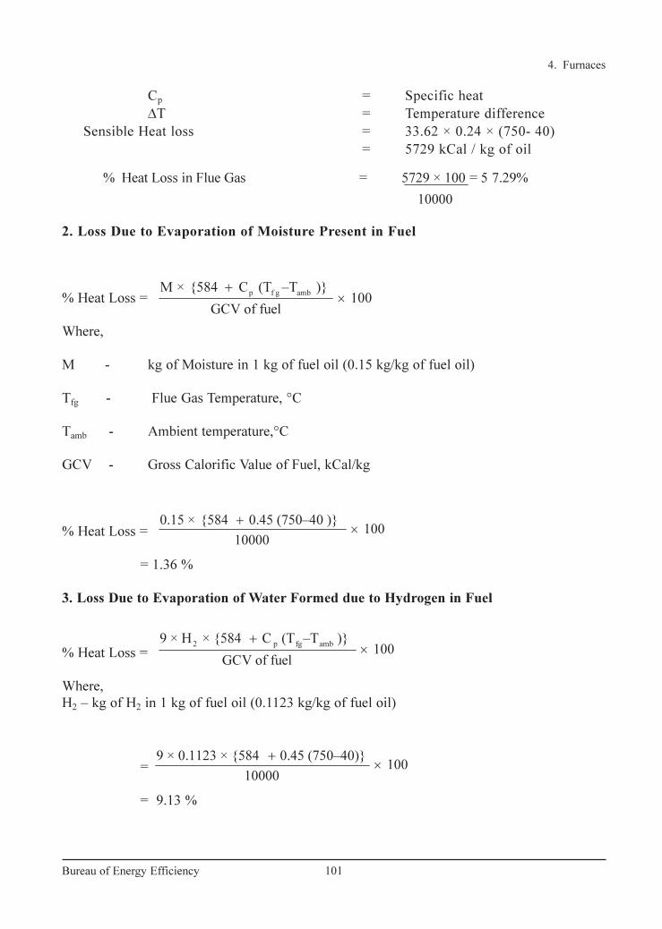
4. Furnaces
101Bureau of Energy Efficiency
Cp = Specific heat
∆T = Temperature difference
Sensible Heat loss = 33.62 × 0.24 × (750- 40)
= 5729 kCal / kg of oil
2. Loss Due to Evaporation of Moisture Present in Fuel
% Heat Loss =
Where,
M - kg of Moisture in 1 kg of fuel oil (0.15 kg/kg of fuel oil)
Tfg - Flue Gas Temperature, °C
Tamb - Ambient temperature,°C
GCV - Gross Calorific Value of Fuel, kCal/kg
% Heat Loss =
= 1.36 %
3. Loss Due to Evaporation of Water Formed due to Hydrogen in Fuel
% Heat Loss =
Where,
H2 – kg of H2 in 1 kg of fuel oil (0.1123 kg/kg of fuel oil)
=
= 9.13 %
9 × 0.1123 × {584 0.45 (750–40)}100
10000
+×
2 p fg amb9 × H × {584 C (T –T )}
100GCV of fuel
+×
0.15 × {584 0.45 (750–40 )} 100
10000
+×
p f g ambM × {584 C (T –T )}
100GCV of fuel
+×
% Heat Loss in Flue Gas = 5729 × 100 = 5 7.29%
10000
Ch-04.qxd 2/23/2005 5:22 PM Page 101

4. Heat Loss due to Openings:
If a furnace body has an opening on it, the heat in the furnace escapes to the outside as
radiant heat. Heat loss due to openings can be calculated by computing black body radiation at
furnace temperature, and multiplying these values with emissivity (usually 0.8 for furnace brick
work), and the factor of radiation through openings. Factor for radiation through openings can
be determined with the help of graph as shown in figure 4.13. The black body radiation losses
can be directly computed from the curves as given in the figure 4.14 below.
The reheating furnace in example has 460 mm thick wall (X) on the billet extraction outlet
side, which is 1m high (D) and 1m wide. With furnace temperature of 1340°C, the quantity (Q)
of radiation heat loss from the opening is calculated as follows:
The shape of the opening is square and D/X = 1/0.46 = 2.17
The factor of radiation (Refer Figure 4.13) = 0.71
Black body radiation corresponding to 1340°C = 36.00 kCal/cm2/hr
(Refer Figure 4.14 on Black body radiation)
Area of opening = 100 cm x 100 cm = 10000 cm2
Emissivity = 0.8
Total heat loss = 36 x 10000 x 0.71 x 0.8
= 204480 kCal/hr
Equivalent fuel oil loss = 20.45 kg/hr
% of heat loss through openings = 20.45 /368 x 100 = 5.56 %
4. Furnaces
102Bureau of Energy Efficiency
Figure 4.13 Factor for Determining the Equivalent of Heat Release from
Openings to the Quality of Heat Release from Perfect Black Body
Ch-04.qxd 2/23/2005 5:22 PM Page 102

5. Heat Loss through Furnace Skin:
a. Heat loss through roof and sidewalls:
Total average surface temperature = 122°C
Heat loss at 122 °C (Refer Fig 4.26) = 1252 kCal / m2 / hr
Total area of heating + soaking zone = 70.18 m2
Total heat loss = 1252 kCal / m2 / hr x 70.18 m2
= 87865 kCal/hr
Equivalent oil loss (a) = 8.78 kg / hr
b.Total average surface temperature of
area other than heating and soaking zone = 80°C
Heat loss at 80°C = 740 kCal / m2 / hr
Total area = 12.6 m2
Total heat loss = 740 kCal / m2 / hr x 12.6 m2
= 9324 kCal/hr
Equivalent oil loss (b) = 0.93 kg / hr
Total loss of fuel oil = a + b = 9.71 kg/hr
Total percentage loss = 9.71 x 100 / 368
= 2.64%
6. Unaccounted Loss
These losses comprises of heat storage loss, loss of furnace gases around charging door and
opening, heat loss by incomplete combustion, loss of heat by conduction through hearth, loss
due to formation of scales.
4. Furnaces
103Bureau of Energy Efficiency
Figure 4.14 Graph for Determining Black Body Radiation at a Particular Temperature
Ch-04.qxd 2/23/2005 5:22 PM Page 103

Furnace Efficiency (Direct Method)
Heat input = 400 litres / hr
= 368 kg/hr
Heat output = m × Cp × ∆T
= 6000 kg × 0.12 × (1340 – 40)
= 936000 kCal
Efficiency = 936000 × 100 / (368 × 10000)
= 25.43 %
= 25% (app)
Losses = 75% (app)
Furnace Efficiency (Indirect Method)
1. Sensible Heat Loss in flue gas = 57.29%
2. Loss due to evaporation of moisture in fuel = 1.36 %
3. Loss due to evaporation of water
formed from H2 in fuel = 9.13 %
4. Heat loss due to openings = 5.56 %
5. Heat loss through skin = 2.64%
Total losses = 75.98%
Furnace Efficiency = 100 – 75.98
= 24.02 %
The instruments required for carrying out performance evaluation in a furnace is given in the
Table 4.2.
4. Furnaces
104Bureau of Energy Efficiency
TABLE 4.2 FURNACE INSTRUMENTATION
Sl. Parameters Location of Instrument Required
No. to be measured Measurement Required Value
1. Furnace soaking Soaking zone side wall Pt/Pt-Rh thermocouple 1200–1300°C
zone temperature with indicator and recorder
(reheating furnaces)
2. Flue gas Flue gas exit from Chromel Alummel 700°C
furnace and entry to Thermocouple with max
re-cuperator indicator
3. Flue gas After recuperator Hg in steel thermometer 300°C (max)
4. Furnace hearth pressure Near charging end side Low pressure +0.1 mm. of Wg
in the heating zone wall over hearth level ring gauge
5. Flue gas analyser Near charging end side Fuel efficiency monitor 02% = 5
wall end side for oxygen & temperature t = 700°C (max)
6. Billet temperature Portable Infrared Pyrometer or ----
optical pyrometer
Ch-04.qxd 2/23/2005 5:22 PM Page 104

4.3 General Fuel Economy Measures in Furnaces
Typical energy efficiency measures for an industry with furnace are:
1) Complete combustion with minimum excess air
2) Correct heat distribution
3) Operating at the desired temperature
4) Reducing heat losses from furnace openings
5) Maintaining correct amount of furnace draught
6) Optimum capacity utilization
7) Waste heat recovery from the flue gases
8) Minimum refractory losses
9) Use of Ceramic Coatings
1. Complete Combustion with Minimum Excess Air:
The amount of heat lost in the flue gases (stack losses) depends upon amount of excess air.
In the case of a furnace carrying away flue gases at 900°C, % heat lost is shown in table 4.3:
4. Furnaces
105Bureau of Energy Efficiency
To obtain complete combustion of fuel with the
minimum amount of air, it is necessary to control
air infiltration, maintain pressure of combustion
air, fuel quality and excess air monitoring
Higher excess air will reduce flame tempera-
ture, furnace temperature and heating rate. On the
other hand, if the excess air is less, then unburnt
components in flue gases will increase and would
be carried away in the flue gases through stack.
The figure 4.15 also indicates relation between air
ratio and exhaust gas loss.
The optimization of combustion air is the most
attractive and economical measure for energy
conservation. The impact of this measure is higher
when the temperature of furnace is high. Air ratio
is the value that is given by dividing the actual air
amount by the theoretical combustion air amount,
and it represents the extent of excess of air. Figure 4.15 Relation Between Air Ratio
and Exhaust Gas Loss
Excess Air % of total heat in the fuel carried away by waste gases
(flue gas temp. 900°C)
25 48
50 55
75 63
100 71
TABLE 4.3 HEAT LOSS IN FLUE GAS BASED ON EXCESS
AIR LEVEL
Ch-04.qxd 2/23/2005 5:22 PM Page 105

4. Furnaces
106Bureau of Energy Efficiency
If a reheating furnace is not equipped with an automatic air/fuel ratio controller, it is
necessary to periodically sample gas in the furnace and measure its oxygen contents by a gas
analyzer. The Figure 4.16 shows a typical example of a reheating furnace equipped with an
automatic air/fuel ratio controller.
More excess air also means more scale losses, which is equally a big loss in terms of money.
2. Proper Heat Distribution:
Furnace design should be such that in a given time, as much of the stock could be heated
uniformly to a desired temperature with minimum fuel firing rate.
Following care should be taken when using burners, for proper heat distribution:
i) The flame should not touch any solid object and should propagate clear of any solid
object. Any obstruction will deatomise the fuel particles thus affecting combustion
and create black smoke. If flame impinges on the stock, there would be increase in
scale losses (Refer Figures 4.17 and 4.18).
ii) If the flames impinge on refractories, the incomplete combustion products can settle
and react with the refractory constituents at high flame temperatures.
iii) The flames of different burners in the furnace should stay clear of each other.
Figure 4.16 Air/Fuel Ratio Control System with Flow Rate Controller
Figure 4.17 Heat Distribution in Furnace
Ch-04.qxd 2/23/2005 5:22 PM Page 106

If they intersect, inefficient combustion would occur. It is desirable to stagger the
burners on the opposite sides.
iv) The burner flame has a tendency to travel freely in the combustion space just above
the material. In small furnaces, the axis of the burner is never placed parallel to the
hearth but always at an upward angle. Flame should not hit the roof.
v) The larger burners produce a long flame, which may be difficult to contain within the
furnace walls. More burners of less capacity give better heat distribution in the
furnace and also increase furnace life.
vi) For small furnaces, it is desirable to have a long flame with golden yellow colour
while firing furnace oil for uniform heating. The flame should not be too long that it
enters the chimney or comes out through the furnace top or through doors. In such
cases, major portion of additional fuel is carried away from the furnace.
3. Maintaining Optimum Operating Temperature of Furnace :
It is important to operate the furnace at optimum temperature. The operating temperatures of
various furnaces are given in Table 4.4.
Operating at too high temperatures than optimum causes heat loss, excessive oxidation, de-
carbonization as well as over-stressing of the refractories. These controls are normally left to
operator judgment, which is not desirable. To avoid human error, on/off controls should be
provided.
4. Prevention of Heat Loss through Openings
Heat loss through openings consists of the heat loss by direct radiation through openings and
the heat loss caused by combustion gas that leaks through openings. The heat loss from an
opening can also be calculated using the following formula:
4. Furnaces
107Bureau of Energy Efficiency
Figure 4.18 Alignment of Burners in Furnace
Slab Reheating furnaces 1200°C
Rolling Mill furnaces 1200°C
Bar furnace for Sheet Mill 800°C
Bogey type annealing furnaces 650°C–750°C
TABLE 4.4 OPERATING TEMPERATURE OF VARIOUS
FURNACES
Ch-04.qxd 2/23/2005 5:22 PM Page 107

where
T: absolute temperature (K)
a: factor for total radiation
A: area of opening, m2
H: time (Hr)
This is explained by an example as follows.
A reheating furnace with walls 460 mm thick (X) has a billet extraction outlet, which is
1 m high (D) and 1 m wide. When the furnace temperature is 1,340°C the quantity (Q) of
radiation heat loss from this opening is evaluated as follows.
The shape of opening is square, and D/X = l/0.46 = 2.17. Thus, the factor for total
radiation is 0.71 (refer Figure 4.13) and we get
If the furnace pressure is slightly higher than outside air pressure (as in case of reheating
furnace) during its operation, the combustion gas inside may blow off through openings and
heat is lost with that. But damage is more, if outside air intrudes into the furnace, making
temperature distribution uneven and oxidizing billets. This heat loss is about 1% of the total
quantity of heat generated in the furnace, if furnace pressure is controlled properly.
5. Control of furnace draft:
If negative pressures exist in the furnace, air infiltration is liable to occur through the cracks and
openings thereby affecting air-fuel ratio control. Tests conducted on apparently airtight furnaces
have shown air infiltration up to the extent of 40%. Neglecting furnaces pressure could mean
problems of cold metal and non-uniform metal temperatures, which could affect subsequent
operations like forging and rolling and result in increased fuel consumption. For optimum fuel
consumption, slight positive pressure should be maintained in the furnace as shown in
Figure 4.19.Ex-filtration is less serious than infiltration. Some of the associated problems with
ex filtration are leaping out of flames, overheating of the furnace refractories leading to reduced
brick life, increased furnace maintenance, burning out of ducts and equipments attached to the
furnace, etc.
In addition to the proper control on furnace pressure, it is important to keep the openings as
small as possible and to seal them in order to prevent the release of high temperature gas and
intrusion of outside air through openings such as the charging inlet, extracting outlet and peep-
hole on furnace walls or the ceiling.
41340 273
4.88 0.71 1 2,34,500kCal/hr100
+ = × × × =
Q
4
4.88100
= × × × ×
TQ a A H
4. Furnaces
108Bureau of Energy Efficiency
Ch-04.qxd 2/23/2005 5:22 PM Page 108

4. Furnaces
109Bureau of Energy Efficiency
6. Optimum Capacity Utilization:
One of the most vital factors affecting efficiency is loading. There is a particular loading at
which the furnace will operate at maximum thermal efficiency. If the furnace is under loaded
a smaller fraction of the available heat in the working chamber will be taken up by the load and
therefore efficiency will be low.
The best method of loading is generally obtained by trial-noting the weight of material put
in at each charge, the time it takes to reach temperature and the amount of fuel used. Every
endeavour should be made to load a furnace at the rate associated with optimum efficiency
although it must be realised that limitations to achieving this are sometimes imposed by work
availability or other factors beyond control.
The loading of the charge on the furnace hearth should be arranged so that
• It receives the maximum amount of radiation from the hot surfaces of the heating chambers
and the flames produced.
• The hot gases are efficiently circulated around the heat receiving surfaces
Stock should not be placed in the following position
• In the direct path of the burners or where flame impingement is likely to occur.
• In an area which is likely to cause a blockage or restriction of the flue system of the furnace.
• Close to any door openings where cold spots are likely to develop.
The other reason for not operating the furnace at optimum loading is the mismatching of
furnace dimension with respect to charge and production schedule.
In the interests of economy and work quality the materials comprising the load should only
remain in the furnace for the minimum time to obtain the required physical and metallurgical
requirements. When the materials attain these properties they should be removed from the
Figure 4.19 Effect of Pressure on the Location of Zero Level and Infiltration of Air
Ch-04.qxd 2/23/2005 5:22 PM Page 109
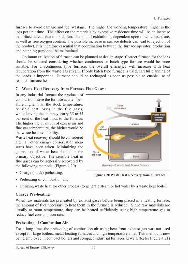
furnace to avoid damage and fuel wastage. The higher the working temperature, higher is the
loss per unit time. The effect on the materials by excessive residence time will be an increase
in surface defects due to oxidation. The rate of oxidation is dependent upon time, temperature,
as well as free oxygen content. The possible increase in surface defects can lead to rejection of
the product. It is therefore essential that coordination between the furnace operator, production
and planning personnel be maintained.
Optimum utilization of furnace can be planned at design stage. Correct furnace for the jobs
should be selected considering whether continuous or batch type furnace would be more
suitable. For a continuous type furnace, the overall efficiency will increase with heat
recuperation from the waste gas stream. If only batch type furnace is used, careful planning of
the loads is important. Furnace should be recharged as soon as possible to enable use of
residual furnace heat.
7. Waste Heat Recovery from Furnace Flue Gases:
In any industrial furnace the products of
combustion leave the furnace at a temper-
ature higher than the stock temperature.
Sensible heat losses in the flue gases,
while leaving the chimney, carry 35 to 55
per cent of the heat input to the furnace.
The higher the quantum of excess air and
flue gas temperature, the higher would be
the waste heat availability.
Waste heat recovery should be considered
after all other energy conservation mea-
sures have been taken. Minimizing the
generation of waste heat should be the
primary objective. The sensible heat in
flue gases can be generally recovered by
the following methods. (Figure 4.20)
• Charge (stock) preheating,
• Preheating of combustion air,
• Utilizing waste heat for other process (to generate steam or hot water by a waste heat boiler)
Charge Pre-heating
When raw materials are preheated by exhaust gases before being placed in a heating furnace,
the amount of fuel necessary to heat them in the furnace is reduced. Since raw materials are
usually at room temperature, they can be heated sufficiently using high-temperature gas to
reduce fuel consumption rate.
Preheating of Combustion Air
For a long time, the preheating of combustion air using heat from exhaust gas was not used
except for large boilers, metal-heating furnaces and high-temperature kilns. This method is now
being employed in compact boilers and compact industrial furnaces as well. (Refer Figure 4.21)
4. Furnaces
110Bureau of Energy Efficiency
Figure 4.20 Waste Heat Recovery from a Furnace
Ch-04.qxd 2/23/2005 5:22 PM Page 110
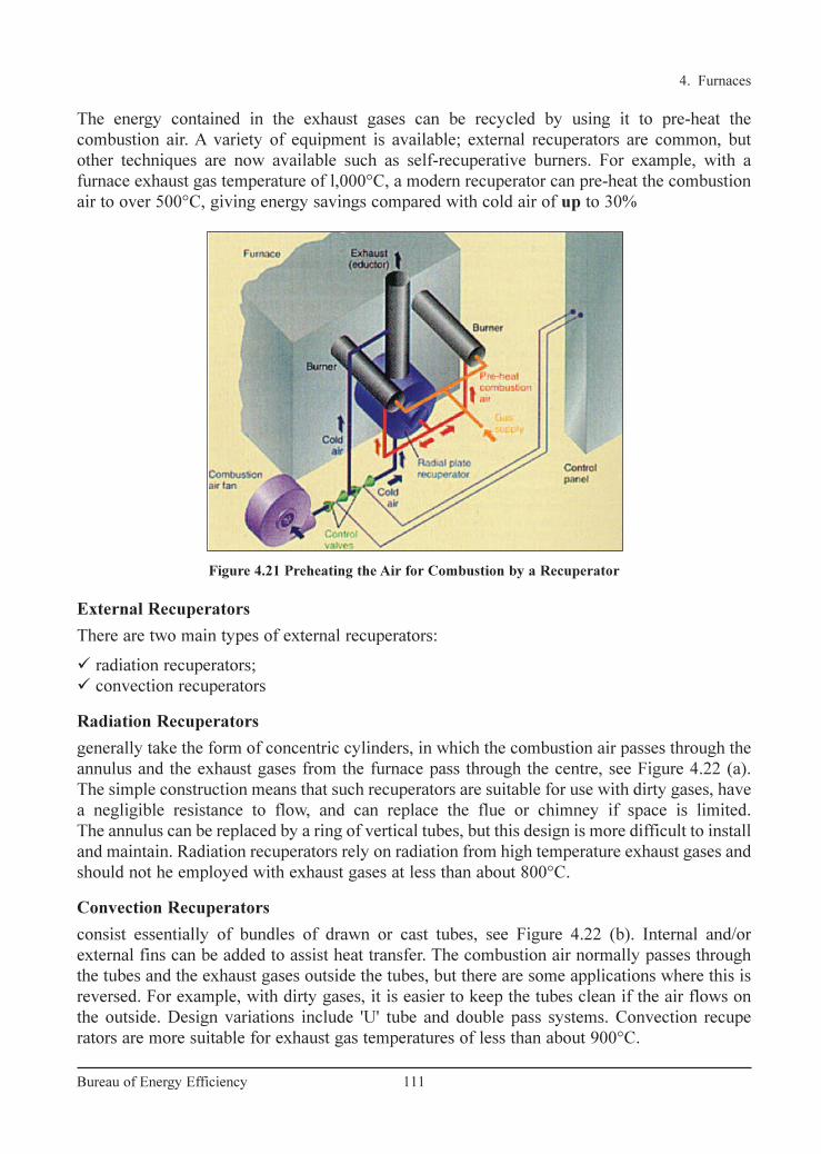
External Recuperators
There are two main types of external recuperators:
� radiation recuperators;
� convection recuperators
Radiation Recuperators
generally take the form of concentric cylinders, in which the combustion air passes through the
annulus and the exhaust gases from the furnace pass through the centre, see Figure 4.22 (a).
The simple construction means that such recuperators are suitable for use with dirty gases, have
a negligible resistance to flow, and can replace the flue or chimney if space is limited.
The annulus can be replaced by a ring of vertical tubes, but this design is more difficult to install
and maintain. Radiation recuperators rely on radiation from high temperature exhaust gases and
should not he employed with exhaust gases at less than about 800°C.
Convection Recuperators
consist essentially of bundles of drawn or cast tubes, see Figure 4.22 (b). Internal and/or
external fins can be added to assist heat transfer. The combustion air normally passes through
the tubes and the exhaust gases outside the tubes, but there are some applications where this is
reversed. For example, with dirty gases, it is easier to keep the tubes clean if the air flows on
the outside. Design variations include 'U' tube and double pass systems. Convection recupe
rators are more suitable for exhaust gas temperatures of less than about 900°C.
4. Furnaces
111Bureau of Energy Efficiency
Figure 4.21 Preheating the Air for Combustion by a Recuperator
The energy contained in the exhaust gases can be recycled by using it to pre-heat the
combustion air. A variety of equipment is available; external recuperators are common, but
other techniques are now available such as self-recuperative burners. For example, with a
furnace exhaust gas temperature of l,000°C, a modern recuperator can pre-heat the combustion
air to over 500°C, giving energy savings compared with cold air of up to 30%
Ch-04.qxd 2/23/2005 5:22 PM Page 111

Self-Recuperative Burners
Self-recuperative burners (SRBs) are based on traditional heat recovery techniques in that the
products of combustion are drawn through a concentric tube recuperator around the burner body
and used to pre-heat the combustion air (Figure 4.23.)
A major advantage of this type of system is that it can be retro-fitted to an existing furnace
structure to increase production capability without having to alter the existing exhaust gas
ducting arrangements. SRBs are generally more suited to heat treatment furnaces where
exhaust gas temperatures are lower and there are no stock recuperation facilities.
4. Furnaces
112Bureau of Energy Efficiency
Figure 4.22 Metallic Recuperators
Figure 4.23 Self-Recuperative Burners
Ch-04.qxd 2/23/2005 5:22 PM Page 112
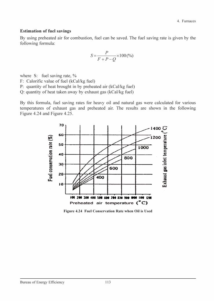
Estimation of fuel savings
By using preheated air for combustion, fuel can be saved. The fuel saving rate is given by the
following formula:
where S: fuel saving rate, %
F: Calorific value of fuel (kCal/kg fuel)
P: quantity of heat brought in by preheated air (kCal/kg fuel)
Q: quantity of heat taken away by exhaust gas (kCal/kg fuel)
By this formula, fuel saving rates for heavy oil and natural gas were calculated for various
temperatures of exhaust gas and preheated air. The results are shown in the following
Figure 4.24 and Figure 4.25.
100(%)= ×+ −
PSF P Q
4. Furnaces
113Bureau of Energy Efficiency
Figure 4.24 Fuel Conservation Rate when Oil is Used
Ch-04.qxd 2/23/2005 5:22 PM Page 113

For example, when combustion air for heavy oil is preheated to 400°C by a heat
exchanger with an inlet temperature of 800 °C, the fuel conservation rate is estimated to be
about 20 percent. When installing a recuperator in a continuous steel reheating furnace, it is
important to choose a preheated air temperature that will balance the fuel saving effect and the
invested cost for the equipment.
Also, the following points should be checked:
• Draft of exhaust gas: When exhaust gas goes through a recuperator, its draft resistance
usually causes a pressure loss of 5–10 mm H2O. Thus, the draft of stack should be checked.
• Air blower for combustion air: While the air for combustion goes through a recuperator,
usually 100–200 mm H2O pressure is lost. Thus, the discharge pressure of air blower should
be checked, and the necessary pressure should be provided by burners.
Since the volume of air is increased owing to its preheating, it is necessary to be careful about
the modification of air-duct diameters and blowers. As for the use of combustion gases
resulting from high-density oils with a high sulphur content, care must be taken to avoid
problems such as clogging with dust or sulphides, corrosion or increases in nitrogen oxides.
Utilizing Waste Heat as a Heat Source for Other Processes
The temperature of heating-furnace exhaust gas can be as high as 400–600 °C, even after heat
has been recovered from it.
When a large amount of steam or hot water is needed in a plant, installing a waste heat boiler
to produce the steam or hot water using the exhaust gas heat is preferred. If the exhaust gas heat
is suitable for equipment in terms of heat quantity, temperature range, operation time etc., the
fuel consumption can be greatly reduced. In one case, exhaust gas from a quenching furnace
was used as a heat source in a tempering furnace so as to obviate the need to use fuel for the
tempering furnace itself.
4. Furnaces
114Bureau of Energy Efficiency
Figure 4.25 Fuel Conservation Rate when Natural Gas is Used
Ch-04.qxd 2/23/2005 5:22 PM Page 114
8. Minimising Wall Losses:
About 30–40% of the fuel input to the furnace generally goes to make up for heat losses in
intermittent or continuous furnaces. The appropriate choice of refractory and insulation
materials goes a long way in achieving fairly high fuel savings in industrial furnaces.
The heat losses from furnace walls affect the fuel economy considerably. The extent of wall
losses depend on:
• Emissivity of wall
• Thermal conductivity of refractories
• Wall thickness
• Whether furnace is operated continuously or intermittently
Heat losses can be reduced by increasing the wall thickness, or through the application of
insulating bricks. Outside wall temperatures and heat losses of a composite wall of a certain
thickness of firebrick and insulation brick are much lower, due to lesser conductivity of
insulating brick as compared to a refractory brick of similar thickness. In the actual operation
in most of the small furnaces the operating periods alternate with the idle periods. During the
off period, the heat stored in the refractories during the on period is gradually dissipated,
mainly through radiation and convection from the cold face. In addition, some heat is
abstracted by air flowing through the furnace. Dissipation of stored heat is a loss, because the
lost heat is again imparted to the refractories during the heat "on" period, thus consuming extra
fuel to generate that heat. If a furnace is operated 24 hours, every third day, practically all the
heat stored in the refractories is lost. But if the furnace is operated 8 hours per day all the heat
stored in the refractories is not dissipated. For a furnace with a firebrick wall of 350 mm
thickness, it is estimated that 55 percent of the heat stored in the refractories is dissipated from
the cold surface during the 16 hours idle period. Furnace walls built of insulating refractories
and cased in a shell reduce the flow of heat to the surroundings.
Prevention of Radiation Heat Loss from Surface of Furnace
The quantity of heat release from surface of furnace body is the sum of natural convection and
thermal radiation. This quantity can be calculated from surface temperatures of furnace. The
temperatures on furnace surface should be measured at as many points as possible, and their
average should be used. If the number of measuring points is too small, the error becomes large.
The quantity (Q) of heat release from a reheating furnace is calculated with the following
formula:
where Q: Quantity of heat released (kCal/hr)
a : factor regarding direction of the surface of natural convection ceiling = 2.8,
side walls = 2.2, hearth = 1.5
tl : temperature of external wall surface of the furnace (°C)
t2 : temperature of air around the furnace (°C)
E: emissivity of external wall surface of the furnace
4 4
5 / 4 1 2
1 2
273 273( ) 4.88
100 100
+ + = × − + × −
t tQ a t t E
4. Furnaces
115Bureau of Energy Efficiency
Ch-04.qxd 2/23/2005 5:22 PM Page 115

The first term of the formula above represents the quantity of heat release by natural
convection, and the second term represents the quantity of heat release by radiation. The
following Figure 4.26 shows the relation between the temperature of external wall surface and
the quantity of heat release calculated with this formula.
This is explained with an example as follows:
There is a reheating furnace
whose ceiling; side walls and
hearth have 20 m2, 50 m2 and 20
m2 of surface area respectively.
Their surface temperatures are
measured, and the averages are
80°C, 90°C and 100°C respec-
tively. Evaluate the quantity of
heat release from the whole
surface of this furnace.
From the Figure 4.26, the
quantities of heat release from
ceiling, side walls and hearth per
unit area are respectively 650
kCal/m2h, 720 kCal/m2h and
730 kCal/m2h.
Therefore, the total quantity of heat release is
Q = 650×20+720×50+730×20
= 13000 + 36000 +14600= 63,600 kCal/hr
Use of Ceramic Fibre
Ceramic fibre is a low thermal mass refractory used in the hot face of the furnace and fastened
to the refractory walls. Due to its low thermal mass the storage losses are minimized. This
results in faster heating up of furnace and also faster cooling. Energy
savings by this application is possible only in intermittent furnaces. More details about
ceramic fibre are given in the chapter on insulation and refractories.
9. Use of Ceramic Coatings
Ceramic coatings in furnace chamber promote rapid and efficient transfer of heat, uniform
heating and extended life of refractories. The emissivity of conventional refractories decreases
4. Furnaces
116Bureau of Energy Efficiency
Figure 4.26 Quantity of Heat Release at Various Temperatures
Ch-04.qxd 2/23/2005 5:22 PM Page 116

4.4 Case Study
In a rerolling mill, following energy conservation measure was implemented and savings
achieved are explained below:
Saving by Installing a Recuperator
This plant had a continuous pusher type billet-reheating furnace. The furnace consists of two
burners at the heating zone. The furnace is having a length of 40 ft. Annual furnace oil
consumption is 620 kL. The furnace did not have any waste heat recovery device. The flue gas
temperature is found to be 650°C. To tap this potential heat the unit has installed a recuperator
device. It was possible to preheat the combustion air to 325°C. By resorting to this measure,
there was 15% fuel saving which is 93 kL of oil per annum.
4. Furnaces
117Bureau of Energy Efficiency
with increase in temperature whereas for ceramic coatings it increases. This outstanding
property has been exploited for use in hot face insulation.
Ceramic coatings are high emissivity coatings which when applied has a long life at
temperatures up to 1350°C. The coatings fall into two general categories-those used for
coating metal substrates, and those used for coating refractory substrates. The coatings are
non-toxic, non-flammable and water based. Applied at room temperatures, they are sprayed and
air dried in less than five minutes. The coatings allow the substrate to maintain its designed
metallurgical properties and mechanical strength. Installation is quick and can be completed
during shut down. Energy savings of the order of 8–20% have been reported depending on the
type of furnace and operating conditions.
10. Fish Bone Diagram for Energy Conservation Analysis in Furnaces
All the possible measures discussed can be incorporated in furnace design and operation.
The figure 4.27 shows characteristics diagram of energy conservation for a fuel-fired furnace.
Figure 4.27 Characteristic Diagram of Energy Conservation for Reheating Furnace
Ch-04.qxd 2/23/2005 5:22 PM Page 117
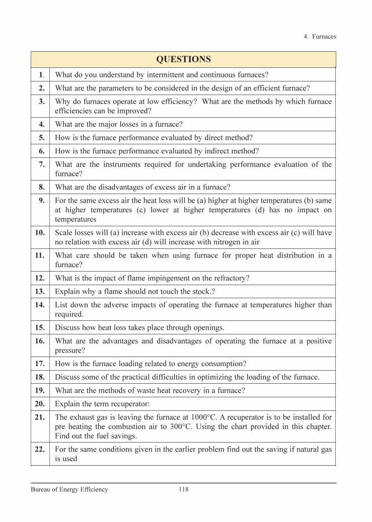
QUESTIONS
1. What do you understand by intermittent and continuous furnaces?
2. What are the parameters to be considered in the design of an efficient furnace?
3. Why do furnaces operate at low efficiency? What are the methods by which furnace
efficiencies can be improved?
4. What are the major losses in a furnace?
5. How is the furnace performance evaluated by direct method?
6. How is the furnace performance evaluated by indirect method?
7. What are the instruments required for undertaking performance evaluation of the
furnace?
8. What are the disadvantages of excess air in a furnace?
9. For the same excess air the heat loss will be (a) higher at higher temperatures (b) same
at higher temperatures (c) lower at higher temperatures (d) has no impact on
temperatures
10. Scale losses will (a) increase with excess air (b) decrease with excess air (c) will have
no relation with excess air (d) will increase with nitrogen in air
11. What care should be taken when using furnace for proper heat distribution in a
furnace?
12. What is the impact of flame impingement on the refractory?
13. Explain why a flame should not touch the stock.?
14. List down the adverse impacts of operating the furnace at temperatures higher than
required.
15. Discuss how heat loss takes place through openings.
16. What are the advantages and disadvantages of operating the furnace at a positive
pressure?
17. How is the furnace loading related to energy consumption?
18. Discuss some of the practical difficulties in optimizing the loading of the furnace.
19. What are the methods of waste heat recovery in a furnace?
20. Explain the term recuperator:
21. The exhaust gas is leaving the furnace at 1000°C. A recuperator is to be installed for
pre heating the combustion air to 300°C. Using the chart provided in this chapter.
Find out the fuel savings.
22. For the same conditions given in the earlier problem find out the saving if natural gas
is used
4. Furnaces
118Bureau of Energy Efficiency
Ch-04.qxd 2/23/2005 5:22 PM Page 118

4. Furnaces
119Bureau of Energy Efficiency
REFERENCES
1. Coal and Industrial Furnaces – Department of Coal Publications, Government of India
2. Fuel Economy in furnaces and Waste heat recovery-PCRA
3. Industrial Furnaces (Vol-2) by W.Trinks, John Wiley and Sons Inc, Newyork, 1925.
4. Output of seminar on energy conservation in iron and steel industry - Sponsored by
United Nations Industrial Development Organization (UNIDO) and Ministry of
International Trade and Industry (MITI), Japan
www.pcra.org
23. What are the precautions to be taken when retrofitting the recuperator in the existing
furnace.
24. Give two examples of utilizing furnace waste heat for other processes.
25. What are the parameters on which the wall losses depends?
26. What are the methods by which wall losses can be reduced?
27. How does ceramic fibre save energy in the furnace?
28. Ceramic fibre gives the maximum savings when used in (a) continuous furnace (b)
batch furnace (c) arc furnace (d) induction furnace
29. How does ceramic coatings help in reducing energy consumption?
30. Explain how you would undertake an energy audit of a batch type heat treatment
furnace.
31. Find out the efficiency of reheating furnaces by direct method from the following data:
a) Dimension of hearth of reheating furnace = 2m × 4m
b) Rate of heating of stock = 125 kg/m2 /hr.
c) Temperature of heated stock = 1030°C
d) Ambient air temperature = 30°C
e) Calorific value of fuel oil = 10200 kCal/kg
f) Specific gravity of fuel oil = 95
g) Fuel consumption during 8 hrs. of shift = 1980 liters.
h) Mean specific heat of stock = 0.6 kCal/kg/K
32. Calculate the radiation heat loss through a opening in the furnace for a period of eight
hours from the data given below
a) a reheating furnace with walls 460 mm thick (X) has a billet extraction outlet which
is 1m high and 1m wide. Furnace operating temperature is 1350°C. The factor total
radiation for the opening is 0.71.
Ch-04.qxd 2/23/2005 5:22 PM Page 119

5. INSULATION AND REFRACTORIES
120Bureau of Energy Efficiency
Syllabus Insulation and Refractories: Insulation-types and application, Economic thickness of insulation, Heat savings and application criteria, Refractory-types, selection and application of refractories, Heat loss.
5.1 Purpose of Insulation
A thermal insulator is a poor conductor of heat and has a low thermal conductivity. Insulationis used in buildings and in manufacturing processes to prevent heat loss or heat gain. Althoughits primary purpose is an economic one, it also provides more accurate control of processtemperatures and protection of personnel. It prevents condensation on cold surfaces and theresulting corrosion. Such materials are porous, containing large number of dormant air cells.Thermal insulation delivers the following benefits:• Reduces over-all energy consumption• Offers better process control by maintaining process temperature.• Prevents corrosion by keeping the exposed surface of a refrigerated system above dew
point• Provides fire protection to equipment• Absorbs vibration
5.2 Types and Application
The Insulation can be classified into three groups according to the temperature ranges for whichthey are used.
Low Temperature Insulations (up to 90 °C)
This range covers insulating materials for refrigerators, cold and hot water systems, storagetanks, etc. The commonly used materials are Cork, Wood, 85% magnesia, Mineral Fibers,Polyurethane and expanded Polystyrene, etc.
Medium Temperature Insulations (90 – 325 °C)
Insulators in this range are used in low temperature, heating and steam raising equipment, steamlines, flue ducts etc. The types of materials used in this temperatures range include 85%Magnesia, Asbestos, Calcium Silicate and Mineral Fibers etc.
High Temperature Insulations (325 °C – above )
Typical uses of such materials are super heated steam system, oven dryer and furnaces etc. Themost extensively used materials in this range are Asbestos, Calcium Silicate, Mineral Fibre,Mica and Vermiculite based insulation, Fireclay or Silica based insulation and Ceramic Fibre.
Ch-05.qxd 2/23/2005 10:45 AM Page 121

5. Insulation & Refractories
121Bureau of Energy Efficiency
Insulation material
Insulation materials can also be classified into organic and inorganic types. Organic insulationsare based on hydrocarbon polymers, which can be expanded to obtain high void structures
Example: Thermocol (Expanded Polystyrene) and Poly Urethane Form(PUF).
Inorganic insulation is based on Siliceous/Aluminous/Calcium materials in fibrous, granular orpowder forms.
Example: Mineral wool, Calcium silicate etc.
Properties of common insulating materials are as under:
Calcium Silicate: Used in industrial process plant piping where high service temperature andcompressive strength are needed. Temperature ranges varies from 40 °C to 950 °C.
Glass mineral wool: These are available in flexible forms, rigid slabs and preformed pipe worksections. Good for thermal and acoustic insulation for heating and chilling system pipelines.Temperature range of application is –10 to 500 °C.
Thermocol: These are mainly used as cold insulation for piping and cold storage construction.
Expanded nitrile rubber: This is a flexible material that forms a closed cell integral vapour barrier. Originally developed for condensation control in refrigeration pipe work and chilled waterlines; now-a-days also used for ducting insulation for air conditioning.
Rock mineral wool: This is available in a range of forms from light weight rolled products to heavy rigid slabs including preformed pipe sections. In addition to good thermal insulation properties, it can also provide acoustic insulation and is fire retardant.
Use of Moulded Insulation
Lagging materials can be obtained in bulk, in the form of moulded sections; semi - cylindrical forpipes, slabs for vessels, flanges, valves etc. The main advantage of the moulded sections is the easeof application and replacement when undertaking repairs for damaged lagging.
The thermal conductivity of a material is the heat loss per unit area per unit insulation thicknessper unit temperature difference. The unit of measurement is W-m2/m°C or W-m/ °C. The thermalconductivity of materials increases with temperature. So thermal conductivity is always specifiedat the mean temperature (mean of hot and cold face temperatures) of the insulation material.
Calcium silicate sections Glass Mineral wool
Figure 5.1
Ch-05.qxd 2/23/2005 10:45 AM Page 122

5. Insulation & Refractories
122Bureau of Energy Efficiency
Thermal conductivities of typical hot and cold insulation materials are given in Table 5.1 andTable 5.2.
5.3 Calculation of Insulation Thickness
The most basic model for insulation on a pipe is shownin Figure 5.2. r1 show the outside radius of the pipe r2shows the radius of the Pipe+ insulation.
Heat loss from a surface is expressed asH = h X A x (Th–Ta)Where
h = Heat transfer coefficient, W/m2–KH = Heat loss, Watts
Figure 5.2 Pipe Insulation
TABLE 5.1 THERMAL CONDUCTIVITY OF HOTINSULATION
TABLE 5.2 THERMAL CONDUCTIVITY OF COLDINSULATION
Ch-05.qxd 2/23/2005 10:45 AM Page 123
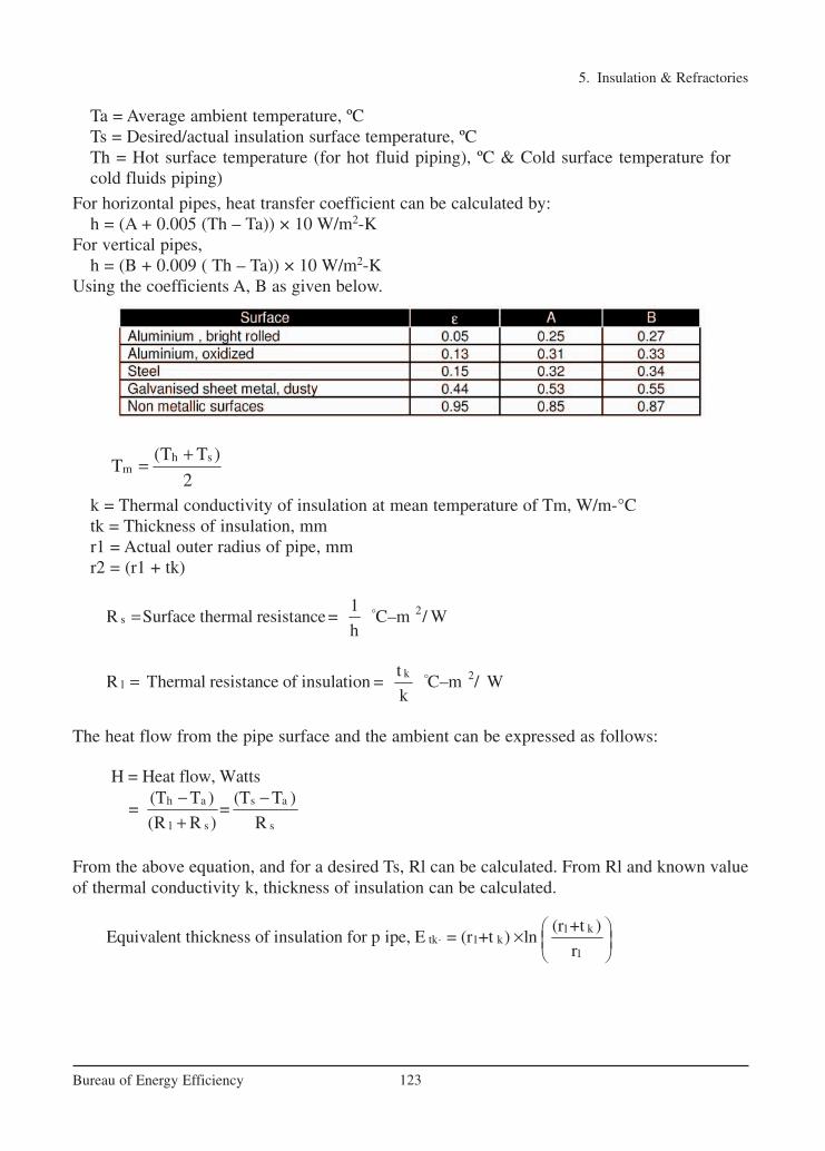
5. Insulation & Refractories
123Bureau of Energy Efficiency
Ta = Average ambient temperature, ºCTs = Desired/actual insulation surface temperature, ºCTh = Hot surface temperature (for hot fluid piping), ºC & Cold surface temperature forcold fluids piping)
For horizontal pipes, heat transfer coefficient can be calculated by:h = (A + 0.005 (Th – Ta)) × 10 W/m2-K
For vertical pipes,h = (B + 0.009 ( Th – Ta)) × 10 W/m2-K
Using the coefficients A, B as given below.
k = Thermal conductivity of insulation at mean temperature of Tm, W/m-°Ctk = Thickness of insulation, mmr1 = Actual outer radius of pipe, mmr2 = (r1 + tk)
The heat flow from the pipe surface and the ambient can be expressed as follows:
From the above equation, and for a desired Ts, Rl can be calculated. From Rl and known valueof thermal conductivity k, thickness of insulation can be calculated.
1 ktk 1 k
1
(r +t )Equivalent thickness of insulation for p ipe, E = (r +t ) ln
r⋅
×
h a s a
l s s
H = Heat flow, Watts(T T ) (T T )
= =(R R ) R
− −+
k 2l
tR Thermal resistance of insulation = C–m / W
k= o
2s
1R Surface thermal resistance = C–m / W
h= o
h sm
(T T )T
2
+=
Ch-05.qxd 2/23/2005 10:45 AM Page 124

5. Insulation & Refractories
124Bureau of Energy Efficiency
5.4 Economic Thickness of Insulation (ETI)
Insulation of any system means capital expenditure. Hence the most important factor in anyinsulation system is to analyse the thermal insulation with respect to cost. The effectiveness ofinsulation follows the law of decreasing returns. Hence, there is a definite economic limit to theamount of insulation, which isjustified. An increased thicknessis uneconomical and cannot berecovered through small heat savings. This limiting value istermed as economic thickness ofinsulation. An illustrative case isgiven in Figure 5.3. Each industryhas different fuel cost and boilerefficiency. These values can beused for calculating economicthickness of insulation. Thisshows that thickness for a givenset of circumstances results in thelowest overall cost of insulationand heat loss combined over a given period of time. The following Figure 5.4 illustrates the principle of economic thickness of insulation.
The simplest method of analysing whether you should use 1" or 2" or 3" insulation is by comparing the cost of energy losses with the cost of insulating the pipe. The insulation thickness for which the total cost is minimum is termed as economic thickness. Refer Figure 5.4 The curve representing the total cost reduces initially and after reaching the economic thickness corresponding to the minimum cost, it increases.
Figure 5.3 Illustration of Optimal Insulation
Figure 5.4 Determination of Economic Thickness of Insulation
Ch-05.qxd 2/23/2005 10:45 AM Page 125

The determination of economic thickness requires the attention to the following factors.i. Cost of fuelii. Annual hours of operationiii. Heat content of fueliv. Boiler efficiencyv. Operating surface temperaturevi. Pipe diameter/thickness of surfacevii. Estimated cost of insulation.viii. Average exposure ambient still air temperature
Procedure for Calculating Economic Thickness of Insulation
To explain the concept of economic thickness of insulation, we will use an example. (Refer Table 5.3) Consider an 8 bar steam pipeline of 6" dia having 50-meter length. We willevaluate the cost of energy losses when we use 1", 2" and 3" insulation to find out the most economic thickness.A step-by-step procedure is given below.
1. Establish the bare pipe surface temperature, by measurement.2. Note the dimensions such as diameter, length & surface area of the pipe section under
consideration.3. Assume an average ambient temperature. Here, we have taken 30 °C.4. Since we are doing the calculations for commercially available insulation thickness,
some trial and error calculations will be required for deciding the surface temperatureafter putting insulation. To begin with assume a value between 55 & 65 °C, which isa safe, touch temperature.
5. Select an insulation material, with known thermal conductivity values in the mean insulation temperature range. Here the mean temperature is 111 °C. and the value of k = 0.044 W/m2 °C for mineral wool.
6. Calculate surface heat transfer coefficients of bare and insulated surfaces, using equations discussed previously. Calculate the thermal resistance and thickness ofinsulation.
7. Select r2 such that the equivalent thickness of insulation of pipe equals to the insulation thickness estimated in step 6. From this value, calculate the radial thickness of pipe insulation = r2-r1
8. Adjust the desired surface temperature values so that the thickness of insulation isclose to the standard value of 1" ( 25.4 mm).
9. Estimate the surface area of the pipe with different insulation thickness and calculatethe total heat loss from the surfaces using heat transfer coefficient, temperature difference between pipe surface and ambient.
10. Estimate the cost of energy losses in the 3 scenarios. Calculate the Net Present Valueof the future energy costs during an insulation life of typically 5 years.
11. Find out the total cost of putting insulation on the pipe ( material + labor cost)12. Calculate the total cost of energy costs and insulation for 3 situations.13. Insulation thickness corresponding to the lowest total cost will be the economic
thickness of insulation.
5. Insulation & Refractories
125Bureau of Energy Efficiency
Ch-05.qxd 2/23/2005 10:45 AM Page 126

5. Insulation & Refractories
126Bureau of Energy Efficiency
Note that the total cost is lower when using 2" insulation, hence is the economic insulationthickness.
TABLE 5.3 EXAMPLE FOR ECONOMIC INSULATION THICKNESS
Ch-05.qxd 2/23/2005 10:45 AM Page 127
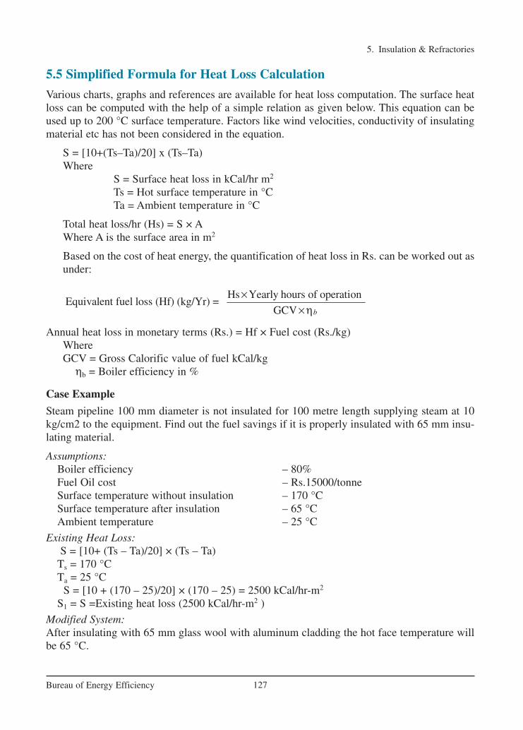
5. Insulation & Refractories
127Bureau of Energy Efficiency
5.5 Simplified Formula for Heat Loss Calculation
Various charts, graphs and references are available for heat loss computation. The surface heatloss can be computed with the help of a simple relation as given below. This equation can beused up to 200 °C surface temperature. Factors like wind velocities, conductivity of insulatingmaterial etc has not been considered in the equation.
S = [10+(Ts–Ta)/20] x (Ts–Ta)Where
S = Surface heat loss in kCal/hr m2
Ts = Hot surface temperature in °CTa = Ambient temperature in °C
Total heat loss/hr (Hs) = S × AWhere A is the surface area in m2
Based on the cost of heat energy, the quantification of heat loss in Rs. can be worked out asunder:
Annual heat loss in monetary terms (Rs.) = Hf × Fuel cost (Rs./kg)Where GCV = Gross Calorific value of fuel kCal/kg
ηb = Boiler efficiency in %
Case Example
Steam pipeline 100 mm diameter is not insulated for 100 metre length supplying steam at 10kg/cm2 to the equipment. Find out the fuel savings if it is properly insulated with 65 mm insu-lating material.
Assumptions:Boiler efficiency – 80%Fuel Oil cost – Rs.15000/tonneSurface temperature without insulation – 170 °CSurface temperature after insulation – 65 °CAmbient temperature – 25 °C
Existing Heat Loss:S = [10+ (Ts – Ta)/20] × (Ts – Ta)
Ts = 170 °CTa = 25 °C
S = [10 + (170 – 25)/20] × (170 – 25) = 2500 kCal/hr-m2
S1 = S =Existing heat loss (2500 kCal/hr-m2 )
Modified System:After insulating with 65 mm glass wool with aluminum cladding the hot face temperature willbe 65 °C.
Hs Yearly hours of operationEquivalent fuel loss (Hf) (kg/Yr) =
GCV b
××η
Ch-05.qxd 2/23/2005 10:45 AM Page 128
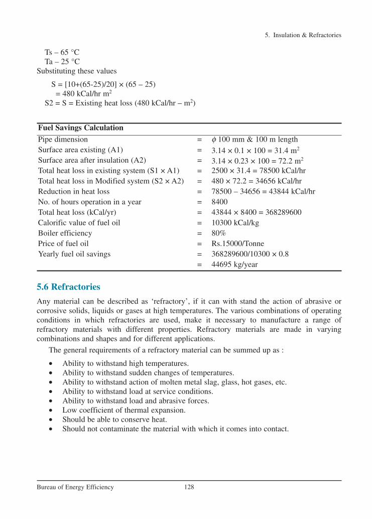
5. Insulation & Refractories
128Bureau of Energy Efficiency
Ts – 65 °CTa – 25 °C
Substituting these values
S = [10+(65-25)/20] × (65 – 25)= 480 kCal/hr m2
S2 = S = Existing heat loss (480 kCal/hr – m2)
5.6 Refractories
Any material can be described as ‘refractory’, if it can with stand the action of abrasive or corrosive solids, liquids or gases at high temperatures. The various combinations of operatingconditions in which refractories are used, make it necessary to manufacture a range of refractory materials with different properties. Refractory materials are made in varying combinations and shapes and for different applications.
The general requirements of a refractory material can be summed up as :
• Ability to withstand high temperatures.• Ability to withstand sudden changes of temperatures.• Ability to withstand action of molten metal slag, glass, hot gases, etc.• Ability to withstand load at service conditions.• Ability to withstand load and abrasive forces.• Low coefficient of thermal expansion.• Should be able to conserve heat.• Should not contaminate the material with which it comes into contact.
Fuel Savings Calculation
Pipe dimension = φ 100 mm & 100 m lengthSurface area existing (A1) = 3.14 × 0.1 × 100 = 31.4 m2
Surface area after insulation (A2) = 3.14 × 0.23 × 100 = 72.2 m2
Total heat loss in existing system (S1 × A1) = 2500 × 31.4 = 78500 kCal/hrTotal heat loss in Modified system (S2 × A2) = 480 × 72.2 = 34656 kCal/hrReduction in heat loss = 78500 – 34656 = 43844 kCal/hrNo. of hours operation in a year = 8400 Total heat loss (kCal/yr) = 43844 × 8400 = 368289600Calorific value of fuel oil = 10300 kCal/kgBoiler efficiency = 80%Price of fuel oil = Rs.15000/TonneYearly fuel oil savings = 368289600/10300 × 0.8
= 44695 kg/year
Ch-05.qxd 2/23/2005 10:45 AM Page 129

5.7 Properties of Refractories
Some of the important properties of refractories are:
Melting point: Pure substances melt sharply at a definite temperature. Most refractory materials consist of high melting particles bonded together. At high temperature, glass fuses andas the temperature rises, the resulting slag increases in quantity by partial solution of the refractory particles. The temperature at which this action results in failure of a test pyramid(cone) to support its own weight is called, for convenience, the melting point of the refractory.Table 5.4 shows the melting point of some pure compounds used as refractories.Size: The size and shape of the refractories is a part of the design feature. It is an important feature in design since it affects the stability of any structure. Accuracy and size is extremelyimportant to enable proper fitting of the refractory shape and to minimize the thickness andjoints in construction.
Bulk density: A useful property of refractories is bulk density, which defines the material present in a given volume. An increase in bulk density of a given refractory increases its volume stability, its heat capacity, as well as resistance to slag penetration.
Porosity: The apparent porosity is a measure of the volume of the open pores, into which a liquid can penetrate, as a percentage of the total volume. This is an important property in caseswhere the refractory is in contact with molten charge and slags. A low apparent porosity is desir-able since it would prevent easy penetration of the refractory size and continuity of pores willhave important influences on refractory behaviour. A large number of small pores is generally preferable to an equivalent number of large pores.
Cold crushing strength: The cold crushing strength, which is considered by some to be ofdoubtful relevance as a useful property, other than that it reveals little more than the ability towithstand the rigors of transport, can be used as a useful indicator to the adequacy of firing andabrasion resistance in consonance with other properties such as bulk density and porosity.
Pyrometric cone equivalent (PCE): Temperature at which a refractory will deform under itsown weight is known as its softening temperature which is indicated by PCE. Refractories, due to their chemical complexity, melt progressively over a range of temperature. Hence refractoriness or fusion point is ideally assessed by the cone fusion method. The equivalent
5. Insulation & Refractories
129Bureau of Energy Efficiency
Pure Compound Formula Melting Temperature °C
Alumina A2O3 2050Lime CaO 2570
Chromite FeOCr2O3 2180
Chromium Oxide Cr2O2 2275
Megnesia MgO 2800
Silica SiO2 1715
Titania TiO2 1850
TABLE 5.4 MELTING POINTS OF PURE COMPOUNDS
Ch-05.qxd 2/23/2005 10:45 AM Page 130
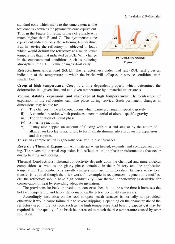
5. Insulation & Refractories
130Bureau of Energy Efficiency
standard cone which melts to the same extent as thetest cone is known as the pyrometric cone equivalent. Thus in the Figure 5.5 refractoriness of Sample A ismuch higher than B and C. The pyrometric coneequivalent indicates only the softening temperature.But, in service the refractory is subjected to loadswhich would deform the refractory at a much lowertemperature than that indicated by PCE. With changein the environmental conditions, such as reducingatmosphere, the P.C.E. value changes drastically.
Refractoriness under load (RUL): The refractoriness under load test (RUL test) gives an indication of the temperature at which the bricks will collapse, in service conditions with similar load.
Creep at high temperature: Creep is a time dependent property which determines the deformation in a given time and at a given temperature by a material under stress.
Volume stability, expansion, and shrinkage at high temperatures: The contraction or expansion of the refractories can take place during service. Such permanent changes in dimensions may be due to:
i) The changes in the allotropic forms which cause a change in specific gravity.ii) A chemical reaction which produces a new material of altered specific gravity.iii) The formation of liquid phase.iv) Sintering reactions.v) It may also happen on account of fluxing with dust and stag or by the action of
alkalies on fireclay refractories, to form alkali-alumina silicates, causing expansionand disruption.
This is an example which is generally observed in blast furnaces.
Reversible Thermal Expansion: Any material when heated, expands, and contracts on cool-ing. The reversible thermal expansion is a reflection on the phase transformations that occurduring heating and cooling.
Thermal Conductivity: Thermal conductivity depends upon the chemical and mineralogicalcompositions as well as the glassy phase contained in the refractory and the application temperature. The conductivity usually changes with rise in temperature. In cases where heattransfer is required though the brick work, for example in recuperators, regenerators, muffles,etc. the refractory should have high conductivity. Low thermal conductivity is desirable for conservation of heat by providing adequate insulation.
The provisions for back-up insulation, conserves heat but at the same time it increases thehot face temperature and hence the demand on the refractory quality increases.
Accordingly, insulation on the roof in open hearth furnaces is normally not provided, otherwise it would cause failure due to severe dripping. Depending on the characteristic of therefractory used in the hot face, such as the high temperature load bearing capacity, it may berequired that the quality of the brick be increased to match the rise temperature caused by overinsulation.
Figure 5.5
Ch-05.qxd 2/23/2005 10:45 AM Page 131

Light weight refractories of low thermal conductivity find wider applications in the moderately low temperature heat treatment furnaces, where its primary function is usually conservation of energy. It is more so in case of batch type furnaces where the low heat capacity of the refractory structure would minimize the heat storage during the intermittentheating and cooling cycles.
5.8 Classification of Refractories
Refractories can be classified on the basis of chemical composition and use and methods ofmanufacture as shown below:
Mineral-based refractories are classified according to their chemical composition:i. Acid bricks contain at least 92%~ silicon oxide (SiO2);ii. Semi-basic bricks contain at least 65% silicon oxide. but less than 30% alumina
(A12O3);iii. Neutral bricks contain at least 30% alumina;iv. Basic bricks contain at least 60% magnesium oxide (MgO).v. Synthetic refractories e.g. silicon carbide are produced by melting and casting
processes.
The structure of the furnace consists mainly of refractory bricks and cement, which must be ableto withstand the high furnace temperatures and must be carefully selected and constructed. Thefurnace structure may contain monolithic refractories, which can be shaped in situ, e.g. thoseused for burner quarls. There are three basic types of monolithic refractories:• Castables;• Mouldables;• Ramming mixtures
Different furnace zones normally operate at different temperatures. The correct selection
5. Insulation & Refractories
131Bureau of Energy Efficiency
Classification based on Chemical composition Examples
ACID which readily combines with bases. Silica, Semisilica, Aluminosilicate.
BASIC which consists mainly of metallic oxides which
resist the action of bases.
Magnesite, chromemagnesite, Dolomite.
NEUTRAL which doesn't combine; neither with acids nor
bases.
Chrome, Pure. Alumina
Special Carbon, Silicon Carbide, Zirconia.
Classification based on end use Blast furnace Casting Pit
Classification based on method of manufacture • Dry Press Process• Fused Cast• Hand Moulded• Formed Normal, fired or Chemically
bonded.)• Unformed (Monolithics – plastics,
Ramming Mass, Gunning Castable,Spraying.)
Ch-05.qxd 2/23/2005 10:45 AM Page 132

5. Insulation & Refractories
132Bureau of Energy Efficiency
of refractory materials for the various parts of the furnace and for various components e.g.hearths, walls, etc, is important. This process is governed not only by properties like thermalconductivity, expansion, etc, but also by the experience of the furnace designer or builder.
The hearth is the most important and the most severely treated region of a furnace. It shouldbe able to bear the required load and withstand chemical attack and mechanical wear. The selection of hearth refractories is less critical for top and bottom fired furnaces, than for topfired only pusher types.
For optimum strength and thermal insulation, the walls, roof and hearth of most furnacesare constructed using layers of refractory materials. Thermal insulation is determined bythe thermal properties of the refractory, and these properties are important in minimising transmission and storage heat losses. Table 5.5 compares the thermal properties of typical high density and low density refractory materials. Structural heat losses can be reduced by using lowthermal mass refractory materials in the construction of the furnace.
5.9 Typical Refractories in Industrial Use
Depending on the area of application such as boilers, furnaces, kilns, ovens etc, temperaturesand atmospheres encountered different types of refractories are used. Typical installations ofrefractories are shown in Figure 5.6
Fireclay Refractories
Fireclay refractories, such as firebricks, siliceous fireclays and aluminous clay refractories consist of aluminium silicates with various amounts of silica ranging from SiO2 content of lessthan 78% and containing less than 44% of Al2O3.
Table 5.6 shows that as the quantity of impurities increases and the amount of Al2O3
Property High Thermal Mass(HighDensity Refractories)
Low Thermal Mass (Ceramic Fibre)
Thermal Conductivity, W/m K 1.2 0.3Specific Heat, J/kg K 1000 1000
Density ,kg/m3 2300 130
TABLE 5.5 TYPICAL REFRACTORY PROPERTIES
Refractory lining of a furnace arch Refractory walls of a furnace interior with burner
blocks
Figure 5.6
Ch-05.qxd 2/23/2005 10:45 AM Page 133

5. Insulation & Refractories
133Bureau of Energy Efficiency
decreases, the melting point of fireclay brick decreases. Owing to its relative cheapness andwidespread location of the raw materials used to manufacture firebricks, this material finds usein most furnaces, kilns, stoves, etc.
Firebrick is the most common form of refractory material. It is used extensively in the ironand steel industry, nonferrous metallurgy, glass industry, pottery kilns, cement industry, and bymany others.
High Alumina Refractories
Alumino silicate refractories containing more than 45% alumina are generally termed as highalumina materials. The alumina concentration ranges from 45 to 100%. The refractoriness ofhigh alumina refractories increases with increase in alumina percentage. The applications ofhigh alumina refractories includes the hearth and shaft of blast furnaces, ceramic kilns, cementkilns, glass tanks and crucibles for melting a wide range of metals.
Silica Brick
Silica brick (or Dinas) is a refractory material containing at least 93% SiO2. The raw materialis quality rocks. Various grades of silica brick have found extensive use in the iron and steelmelting furnaces. In addition to high fusion point multi-type refractories, the other importantproperties are their high resistance to thermal shock (spalling) and their high refractoriness. Itfinds typical use in glass making and steel industry.
The outstanding property of silica brick is that it does not begin to soften under high loadsuntil its fusion point is approached. This behaviour contrasts with that of many other refracto-ries, for example alumino silicate materials, which begin to fuse and creep at temperatures con-siderably lower than their fusion points. Other advantages are flux and stag resistance, volumestability and high spalling resistance.
Magnesite
Magnesite refractories are chemically basic materials, containing at least 85% magnesiumoxide. They are made from naturally occurring magnesite (MgCO3). The properties of magne-site refractories depend on the concentration of silicate bond at the operating temperatures.Good quality magnesite usually results from a CaO-SiO2 ratio of less than 2 with a minimumferrite concentration, particularly if the furnaces lined with the refractory operate in oxidizingand reducing conditions. The slag resistance is very high particularly to lime and iron rich slags.
Brick Percent SiO2 Percent Al2O3 Other Constituents PCE °C
Super Duty 49-53 40−44 5-7 1745-1760
High Duty 50-80 35-40 5-9 1690-1745
Intermediate 60-70 26-36 5-9 1640-1680
HighDuty (Siliceous) 65-80 18-30 3-8 1620-1680
Low Duty 60-70 23-33 6-10 1520-1595
TABLE 5.6 PROPERTIES OF TYPICAL FIRECLAY BRICKS
Ch-05.qxd 2/23/2005 10:45 AM Page 134

Chromite Refractories
Here, a distinction must be made between chrome-magnesite refractories and magnesite-chromite-refractories. Chromemagnesite material usually contain 15-35% Cr2O3 and 42-50%MgO whereas magnesite-chromite refractories contain at least 60% MgO and 8-18% Cr2O3.
Chrome-magnesite refractories are made in a wide range of qualities and are used for build-ing the critical parts of high temperature furnaces. These materials can withstand corrosiveslags and gases and have high refractoriness. The magnesite-chromite products are suitable forservice at the highest temperatures and in contact with the most basic slags used in steel melt-ing. Magnesite-chromite usually ahs a better spalling resistance than chrome-magnesite.
Zirconia Refractories
Zirconium dioxide (ZrO2) is a polymorphic, material. There are certain difficulties in its usageand fabrication as a refractory material. It is essential to stabilize it before application as arefractory. This is achieved by incorporating small quantities of calcium, magnesium and ceri-um oxide, etc. Its properties depend mainly on the degree of stabilization and quantity of stabi-lizer as well as the quality of the original raw material. Zirconia refractories have a very highstrength at room temperature which is maintained upto temperatures as high as 1500 °C. Theyare, therefore, useful as high temperature constructional materials for furnaces and kilns. Thethermal conductivity, of zirconium dioxide is found to be much lower than that of most otherrefractories and the material is therefore used as a high temperature insulating refractory.
Since Zirconia exhibits very low thermal losses and does not react readily with liquid metals, it is particularly useful for making refractory crucibles and other vessels for metallurgical purposes. Zirconia is a useful refractory material for glass furnaces primarilysince it is not easily wetted by molten glasses and because of its low reaction with them.
Oxide Refractories (Alumina)
Alumina refractory materials which consist of aluminium oxide with little traces of impuritiesare often known as pure alumina. Alumina is one of the most chemically stable oxides known.It is mechanically very strong, insoluble in water and super heated steam, and in most inorgan-ic acids and alkalies. Its properties make it suitable for the shaping of crucibles for fusing sodi-um carbonate, sodium hydroxide and sodium peroxide. It has a high resistance in oxidizing andreducing atmosphere. Alumina is extensively used in heat processing industries. Highly porousalumina is used for lining furnaces operating up to 1850 °C.
Monolithics
Monolithic refractories (single piece cast in the shape of equipment such as one for a ladle shown in Figure 5.7) arereplacing the conventional type fired refractories at a muchfaster rate in many applications including those of industrialfurnaces. The main advantages being: • It eliminates joints which is an inherent weakness• Method of application is faster and skilled measures in
large number are not required• Transportation and handling are simple• Offers better scope to reduce downtime for repairs
5. Insulation & Refractories
134Bureau of Energy Efficiency
Figure 5.7 Monolithic Lining for a Ladle
Ch-05.qxd 2/23/2005 10:45 AM Page 135

• Offers considerable scope to reduce inventory and eliminate special shapes• It is a heat saver• Has better spalling resistance• Has greater volume stability
Various means are employed in the placement of monolithics like ramming, casting, gunniting,spraying, sand slinging, etc. Ramming masses are used mostly in cold applications where proper consolidation of the material is important. The same practice can be adopted with bothair setting and heat setting materials. Proper ramming tools need to be selected.
Castables by name implies a material of hydraulic setting in nature. Calcium aluminatecement being the binder, it will have to be stored properly to prevent moisture absorption.Further its strength starts deteriorating after a period of 6 to 12 months.
Insulating Materials
Insulating materials greatly reduce the heat losses through walls. Insulation is effected by providing a layer of material having a low heat conductivity between the internal hot surface ofa furnace and the external surface, thus causing the temperature of the external surface reduced.
The insulating materials may be classified into the following groups:• Insulating bricks• Insulating Castables• Ceramic fibre• Calcium silicate• Ceramic coating
Insulating materials owe their low conductivity to their pores while their heat capacity dependson the bulk density and specific heat. Structure of air insulating material consists of minutepores filled with air which have in themselves very low thermal conductivity, excessive heataffects all insulation material adversely, but the temperatures to which the various materials canbe heated before this adverse effect occurs differ widely. Clearly, therefore, the choice of aninsulating material must depend upon its effectiveness to resist heat conductivity and upon thetemperature that it will withstand.
One of the most widely used insulating materials is diatomite, also known as kiesel guhrwhich is made up of a mass of skeletons of minute aquatic plants deposited thousands of yearsago on the beds of seas and lakes. Chemically this consists of silica contaminated with clay andorganic matter. A wide range of insulating refractories with wide combinations of properties arenow available.
The important physical properties of some insulating refractories are shown in the Table 5.7.
5. Insulation & Refractories
135Bureau of Energy Efficiency
Type Thermal conductivity at 400 °C
Max. safe temperature °C
Cold CrushingStrength Kg/cm2
Porosity%
Bulk densityKg/m3
Diatomite Solid Grade 0.025 1000 270 52 1090
Diatomite Porous Grade 0.014 800 110 77 540
Clay 0.030 1500 260 68 560
High Aluminia 0.028 1500–1600 300 66 910Silica 0.040 1400 400 65 830
TABLE 5.7 PHYSICAL PROPERTIES OF INSULATING REFRACTORIES
Ch-05.qxd 2/23/2005 10:45 AM Page 136

Castables and Concretes
Monolithic linings and furnace sections can be built up by casting refractory insulating concretes, and by stamping into place certain light weight aggregates suitably bonded. Otherapplications include the formation of the bases of tunnel kiln cars used in the ceramic industry.The ingredients are similar to those used for making piece refractories, except that concretescontain some kind of cement, either Portland or a high-alumina cement.
Ceramic Fibre
Ceramic fibre is a low thermal mass insulation material, which has revolutionalised the furnace designlining systems.
Ceramic fibre is an alumino silicate material manufactured by blending and melting alumina and silica at temperature of 1800 - 2000 °C and breakingthe molten stream by blowing compressed air or drop-ping the melt on spinning disc to form loose or bulkceramic fibre. The bulk fibre is converted to various products including blanket, strips, veneeringand anchored modules, paper, vacuum formed boardsand shapes, rope, wet felt, mastic cement etc. for insulation applications.
Fibres are usually produced in two temperature grades based on Al2O3 content. A recentaddition is ZrO2 added alumino silicate fibre, which helps to reduce shrinkage levels therebyrating the fibre for higher temperatures. Continuous recommended operating temperature forfibres are given in the following Table 5.8:
These fibres are generally produced in bulk wool form and needled into blanket mass of various densities ranging from 64 to 190 kg/m3. Converted products and over 40 different formsare made from blankets to suit various requirements.
Important Properties of Ceramic Fibre
The characteristics of ceramic fibres are a remarkable combination of the properties of refrac-tories and traditional insulation material.
1. Lower Thermal ConductivityThe low thermal conductivity - 0.1 kCal/m hour deg C at 600 °C for 128 kg/m3 density blanket- allows construction of thinner linings with the same thermal efficiency as that of conventional refractories. Hence, for the same outer envelope dimension the furnace volume is much
5. Insulation & Refractories
136Bureau of Energy Efficiency
A12O3 SiO2 ZrO2
1150 °C 43 – 47% 53 – 57% –
1250 °C 52 – 56% 44 – 48% –
1325 °C 33 – 35% 47 – 50% 17 – 20%
TABLE 5.8 CONTINUOUS RECOMMENDED OPERATING TEMPERATURE FOR FIBRES
Figure 5.8 Ceramic Fibre Insulation
Ch-05.qxd 2/23/2005 10:45 AM Page 137

higher. It is 40 % more effective than good quality insulation brick and 2.5 times better thanasbestos product. Insulating property of ceramic fibre is better than calcium silicate product.
2. Light WeightAverage density of ceramic fibre is 96 kg/m3. It is one tenth of the weight of insulating brickand one third that of asbestos / calcium silicate boards. For new furnaces structural supports canbe reduced by 40%.
3. Lower Heat StorageCeramic fibre linings absorb less heat because of lower density. Furnace can be heated andcooled at faster rates. Typically the heat stored in a ceramic fibre lining system is in the rangeof 2700 - 4050 kCal/m2 (1000 - 1500 Btu/Ft2) as compared to 54200-493900 kCal/m2
(20000 - 250000 Btu/Ft2) for conventionally lined system.
4. Thermal Shock ResistantCeramic fibre lining resist thermal shock due to their resilient matrix. Also faster heat up andcool down cycles are possible thereby improving furnace availability and productivity.
5. Chemical ResistanceCeramic fibre resist most of the chemical attack and is unaffected by hydrocarbons, water andsteam present in flue gases.
6. Mechanical ResilienceThis property permits fibre lined furnaces to be shop fabricated and shipped to site in assembled form without fear of damage.
7. Low Installation CostNo special skills are required as application practices are standardised. Fibre linings require nodry out or curing times and can be heated to the capacity of the burners after installation is completed without concern for cracking or spalling.
8. Simple MaintenanceIn case of physical damage the defective section can be quickly removed and a replacementpiece added. Whole panel sections can be prefabricated for fast installation with minimal downtime.
9. Ease of HandlingAll product forms are easily handled and most can be quickly cut with a knife or scissors.Vacuum formed products may require cutting with a band saw.
10. Thermal EfficiencyThe low thermal conductivity of ceramic fibre can be advantageously made use of by the lesser lining thickness and reduced furnace volume. The fast response of ceramic fibre lined fur-nace also allows for more accurate control and uniform temperature distribution within the fur-nace.The other advantages offered by ceramic fibre are summarized below:• Light weight furnace• Simple steel fabrication work
5. Insulation & Refractories
137Bureau of Energy Efficiency
Ch-05.qxd 2/23/2005 10:45 AM Page 138
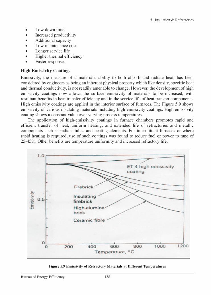
• Low down time• Increased productivity• Additional capacity• Low maintenance cost• Longer service life• Higher thermal efficiency• Faster response.
High Emissivity Coatings
Emissivity, the measure of a material's ability to both absorb and radiate heat, has been considered by engineers as being an inherent physical property which like density, specific heatand thermal conductivity, is not readily amenable to change. However, the development of highemissivity coatings now allows the surface emissivity of materials to be increased, with resultant benefits in heat transfer efficiency and in the service life of heat transfer components.High emissivity coatings are applied in the interior surface of furnaces. The Figure 5.9 showsemissivity of various insulating materials including high emissivity coatings. High emissivitycoating shows a constant value over varying process temperatures.
The application of high-emissivity coatings in furnace chambers promotes rapid and efficient transfer of heat, uniform heating, and extended life of refractories and metallic components such as radiant tubes and heating elements. For intermittent furnaces or whererapid heating is required, use of such coatings was found to reduce fuel or power to tune of 25-45%. Other benefits are temperature uniformity and increased refractory life.
5. Insulation & Refractories
138Bureau of Energy Efficiency
Figure 5.9 Emissivity of Refractory Materials at Different Temperatures
Ch-05.qxd 2/23/2005 10:45 AM Page 139
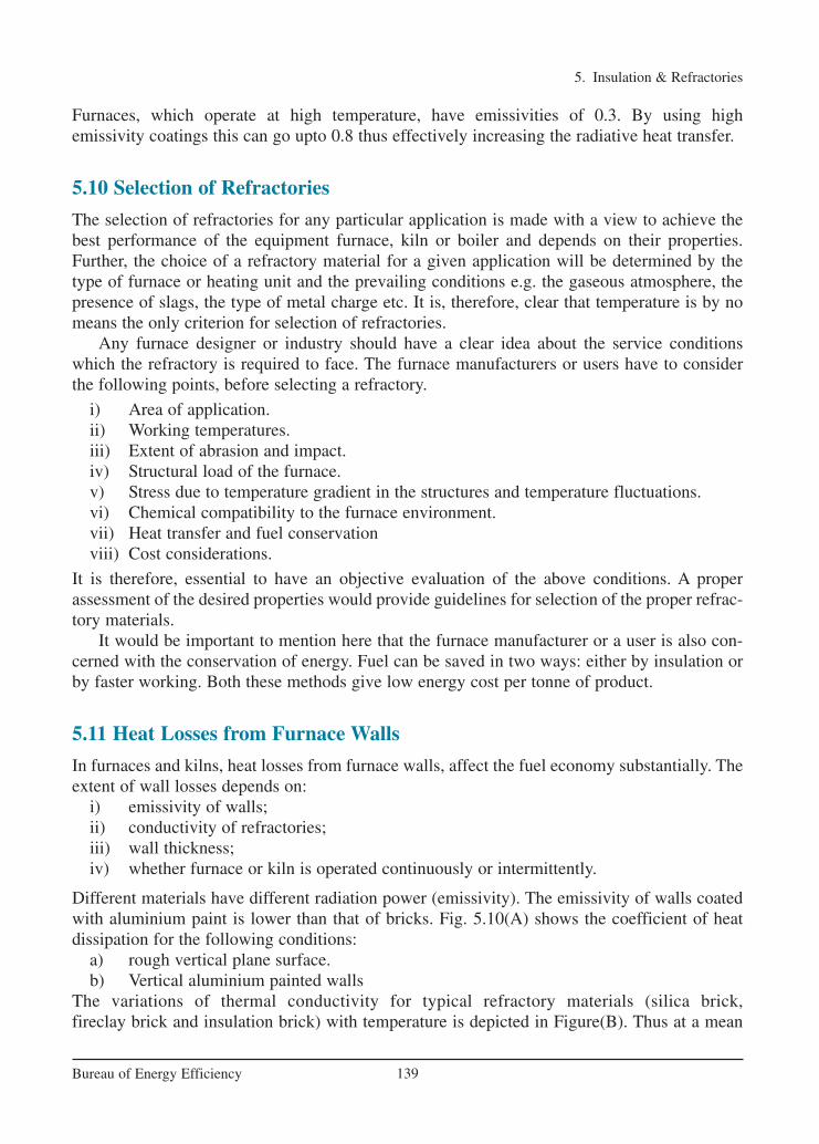
Furnaces, which operate at high temperature, have emissivities of 0.3. By using high emissivity coatings this can go upto 0.8 thus effectively increasing the radiative heat transfer.
5.10 Selection of Refractories
The selection of refractories for any particular application is made with a view to achieve thebest performance of the equipment furnace, kiln or boiler and depends on their properties.Further, the choice of a refractory material for a given application will be determined by thetype of furnace or heating unit and the prevailing conditions e.g. the gaseous atmosphere, thepresence of slags, the type of metal charge etc. It is, therefore, clear that temperature is by nomeans the only criterion for selection of refractories.
Any furnace designer or industry should have a clear idea about the service conditionswhich the refractory is required to face. The furnace manufacturers or users have to considerthe following points, before selecting a refractory.
i) Area of application.ii) Working temperatures.iii) Extent of abrasion and impact.iv) Structural load of the furnace.v) Stress due to temperature gradient in the structures and temperature fluctuations.vi) Chemical compatibility to the furnace environment.vii) Heat transfer and fuel conservationviii) Cost considerations.
It is therefore, essential to have an objective evaluation of the above conditions. A properassessment of the desired properties would provide guidelines for selection of the proper refrac-tory materials.
It would be important to mention here that the furnace manufacturer or a user is also con-cerned with the conservation of energy. Fuel can be saved in two ways: either by insulation orby faster working. Both these methods give low energy cost per tonne of product.
5.11 Heat Losses from Furnace Walls
In furnaces and kilns, heat losses from furnace walls, affect the fuel economy substantially. Theextent of wall losses depends on:
i) emissivity of walls;ii) conductivity of refractories;iii) wall thickness;iv) whether furnace or kiln is operated continuously or intermittently.
Different materials have different radiation power (emissivity). The emissivity of walls coatedwith aluminium paint is lower than that of bricks. Fig. 5.10(A) shows the coefficient of heat dissipation for the following conditions:
a) rough vertical plane surface.b) Vertical aluminium painted walls
The variations of thermal conductivity for typical refractory materials (silica brick, fireclay brick and insulation brick) with temperature is depicted in Figure(B). Thus at a mean
5. Insulation & Refractories
139Bureau of Energy Efficiency
Ch-05.qxd 2/23/2005 10:45 AM Page 140
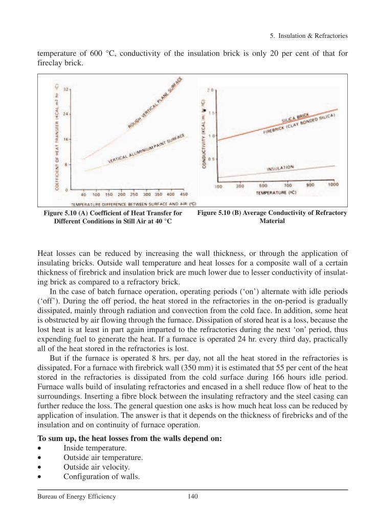
temperature of 600 °C, conductivity of the insulation brick is only 20 per cent of that for fireclay brick.
Heat losses can be reduced by increasing the wall thickness, or through the application of insulating bricks. Outside wall temperature and heat losses for a composite wall of a certainthickness of firebrick and insulation brick are much lower due to lesser conductivity of insulat-ing brick as compared to a refractory brick.
In the case of batch furnace operation, operating periods (‘on’) alternate with idle periods(‘off’). During the off period, the heat stored in the refractories in the on-period is gradually dissipated, mainly through radiation and convection from the cold face. In addition, some heatis obstructed by air flowing through the furnace. Dissipation of stored heat is a loss, because thelost heat is at least in part again imparted to the refractories during the next ‘on’ period, thusexpending fuel to generate the heat. If a furnace is operated 24 hr. every third day, practicallyall of the heat stored in the refractories is lost.
But if the furnace is operated 8 hrs. per day, not all the heat stored in the refractories is dissipated. For a furnace with firebrick wall (350 mm) it is estimated that 55 per cent of the heatstored in the refractories is dissipated from the cold surface during 166 hours idle period.Furnace walls build of insulating refractories and encased in a shell reduce flow of heat to thesurroundings. Inserting a fibre block between the insulating refractory and the steel casing canfurther reduce the loss. The general question one asks is how much heat loss can be reduced byapplication of insulation. The answer is that it depends on the thickness of firebricks and of theinsulation and on continuity of furnace operation.
To sum up, the heat losses from the walls depend on:• Inside temperature.• Outside air temperature.• Outside air velocity.• Configuration of walls.
5. Insulation & Refractories
140Bureau of Energy Efficiency
Figure 5.10 (A) Coefficient of Heat Transfer forDifferent Conditions in Still Air at 40 °C
Figure 5.10 (B) Average Conductivity of RefractoryMaterial
Ch-05.qxd 2/23/2005 10:45 AM Page 141

• Emissivity of walls.• Thickness of walls.• Conductivity of walls.
The following conclusions can be drawn: • Thickness of walls and Conductivity of walls can be easily controlled by the furnace
fabricator.• As the wall thickness increases, the heat losses reduce.• As thickness of insulation is increased, heat losses reduce.• The effect of insulation in reducing heat losses is more pronounced than the increase
of wall thickness. Roughly 1 cm of insulation brick is equivalent to 5 to 8 cm of refractory (firebrick).
• In intermittent furnaces, thin walls of insulating refractories are preferable to thickwalls of a normal refractory for intermittent operation since less heat is stored in them.
• One approach to achieve less heat storage capacity would be to utilise insulating material itself to form the inner refractory lining. Robust refractories with fairly goodstrength and spalling resistance can be used for temperatures in the range of 1300 °C.They are termed as hot face insulation.
• Hot face insulating bricks are lighter than normal refractories, weighing only one-thirdto one-half as much. Therefore, heat storage in the hot face insulation is very muchreduced.
5. Insulation & Refractories
141Bureau of Energy Efficiency
Ch-05.qxd 2/23/2005 10:45 AM Page 142
5. Insulation & Refractories
142Bureau of Energy Efficiency
QUESTIONS
1.
A thermal insulator has(a) low thermal conductivity (b) high thermal conductivity(c) high convection co-efficient (d) low convection co-efficient
2. What are the benefits of insulation other than heat loss / heat gain?
3. Give examples of materials for medium temperature insulations.
4. Give examples of materials for high temperature insulations.
5. State the advantages of moulded insulations.
6. Explain the term economic thickness of insulation.
7. Of the following which are the property is most important for an insulating brick(a) Porosity (b) Mechanical strength (c) Chemical property (d) Compact strength
8. What are castables ?
9. Explain briefly how ceramic fibre is made.
10. Which of the following when added to alumino silicate helps to reduce the shrinkagelevel of ceramic fibre(a) Zr O2 (b) SiO2 (c) Al2O3 (d) CaSO4
11. The term blanket refers to(a) Ceramic fibre (b) Refractory brick(c) Insulating brick (d) Castables
12. Explain the advantages of ceramic fibre with respective properties.
13. Find out from the figure given in this chapter, the emissivity at 1000 °C for the following:(a) fire brick (b) high alumina brick(c) ceramic fibre (d) high emissivity coatings
14. Name the three classifications of refractories on the basis of chemical composition.
15. The most common refractory used in furnaces is(a) fire brick (b) zirconia brick (c) magnesite brick (d) silica brick
16. State briefly the criteria of selection of refractories.
REFERENCES
1. Handbook on Refractories by D.N.Nandi, Tata McGraw, New Delhi, 1987.2. Thermal Insulation and Refractories -PCRA.3. Insulation and Refractories - British Energy Efficiency Office.4. Handbook on Refractories by D N Nandi, Tata McGraw-Hill Publishing Company
Limited, New Delhi.www.seav.vic.gov.au/ftp/advice/business/info_sheets/EnergySaving-Insulatio_0_a.pdfwww.pcra.org
Ch-05.qxd 2/23/2005 10:45 AM Page 143

6. FBC BOILERS
143Bureau of Energy Efficiency
Syllabus
FBC boilers: Introduction, Mechanism of fluidised bed combustion, Advantages, Typesof FBC boilers, Operational features, Retrofitting FBC system to conventional boilers,Saving potential.
6.1 Introduction
The major portion of the coal available in India is of low quality, high ash content and lowcalorific value. The traditional grate fuel firing systems have got limitations and are techno-eco-nomically unviable to meet the challenges of future. Fluidised bed combustion has emerged asa viable alternative and has significant advantages over conventional firing system and offersmultiple benefits – compact boiler design, fuel flexibility, higher combustion efficiency andreduced emission of noxious pollutants such as SOx and NOx. The fuels burnt in these boilersinclude coal, washery rejects, rice husk, bagasse and other agricultural wastes. The fluidizedbed boilers have a wide capacity range- 0.5 T/hr to over 100 T/hr.
6.2 Mechanism of Fluidised Bed Combustion
When an evenly distributed air or gas is passed upward through a finely divided bed of solidparticles such as sand supported on a fine mesh, the particles are undisturbed at low velocity.As air velocity is gradually increased, a stage is reached when the individual particles aresuspended in the air stream – the bed is called “fluidised”.
With further increase in air velocity, there is bubble formation, vigorous turbulence, rapidmixing and formation of dense defined bed surface. The bed of solid particles exhibits theproperties of a boiling liquid and assumes the appearance of a fluid – “bubbling fluidized bed”.
At higher velocities, bubbles disappear, and particles are blown out of the bed. Therefore, someamounts of particles have to be recirculated to maintain a stable system - "circulating fluidised bed".
This principle of fluidisation is illustrated in Figure 6.1.Fluidization depends largely on the particle size and the air velocity. The mean solids velocity
increases at a slower rate than does the gas velocity, as illustrated in Figure 6.2. The differencebetween the mean solid velocity and mean gas velocity is called as slip velocity. Maximum slipvelocity between the solids and the gas is desirable for good heat transfer and intimate contact.
If sand particles in a fluidised state is heated to the ignition temperatures of coal, and coal isinjected continuously into the bed, the coal will burn rapidly and bed attains a uniform temperature.The fluidised bed combustion (FBC) takes place at about 840°C to 950°C. Since this temperatureis much below the ash fusion temperature, melting of ash and associated problems are avoided.
The lower combustion temperature is achieved because of high coefficient of heat transferdue to rapid mixing in the fluidised bed and effective extraction of heat from the bed throughin-bed heat transfer tubes and walls of the bed. The gas velocity is maintained between mini-mum fluidisation velocity and particle entrainment velocity. This ensures stable operation of the
Ch-06.qxd 2/23/2005 11:24 AM Page 143

bed and avoids particle entrainment in the gas stream.Combustion process requires the three “T”s that is Time, Temperature and Turbulence.
In FBC, turbulence is promoted by fluidisation. Improved mixing generates evenly
6. FBC Boilers
144Bureau of Energy Efficiency
Figure 6.1 Principle of Fluidisation
Figure 6.2 Relation between Gas Velocity and Solid Velocity
Fixing, bubbling andfast fluidized beds
As the velocity of agas flowing through abed of particlesincreases, a value is reaches whenthe bed fluidises andbubbles form as in aboiling liquid. At higher velocities thebubbles disappear; andthe solids are rapidlyblown out of the bedand must be recycled tomaintain a stable system.
Ch-06.qxd 2/23/2005 11:24 AM Page 144

distributed heat at lower temperature. Residence time is many times greater thanconventional grate firing. Thus an FBC system releases heat more efficiently at lowertemperatures.
Since limestone is used as particle bed, control of sulfur dioxide and nitrogen oxideemissions in the combustion chamber is achieved without any additional control equipment.This is one of the major advantages over conventional boilers.
6.3 Types of Fluidised Bed Combustion Boilers
There are three basic types of fluidised bed combustion boilers:
1. Atmospheric classic Fluidised Bed Combustion System (AFBC) 2. Atmospheric circulating (fast) Fluidised Bed Combustion system(CFBC)3. Pressurised Fluidised Bed Combustion System (PFBC).
6.3.1 AFBC / Bubbling Bed
In AFBC, coal is crushed to a size of 1 – 10 mm depending on the rank of coal, type of fuel feedand fed into the combustion chamber. The atmospheric air, which acts as both the fluidization airand combustion air, is delivered at a pressure and flows through the bed after being preheated bythe exhaust flue gases. The velocity of fluidising air is in the range of 1.2 to 3.7 m /sec. The rateat which air is blown through the bed determines the amount of fuel that can be reacted.
Almost all AFBC/ bubbling bed boilers use in-bed evaporator tubes in the bed of limestone,sand and fuel for extracting the heat from the bed to maintain the bed temperature. The bed depthis usually 0.9 m to 1.5 m deep and the pressure drop averages about 1 inch of water per inch of beddepth. Very little material leaves the bubbling bed – only about 2 to 4 kg of solids are recycled per
6. FBC Boilers
145Bureau of Energy Efficiency
Figure 6.3 Bubbling Bed Boiler-1
Features of bubbling bed boiler
Fluidised bed boiler can operate at near atmospheric or elevated pressure and have theseessential features:• Distribution plate through which air is blown
for fluidizing.• Immersed steam-raising or water heating
tubes which extract heat directly from the bed.• Tubes above the bed which extract heat from
hot combustion gas before it enters the flueduct.
Ch-06.qxd 2/23/2005 11:24 AM Page 145
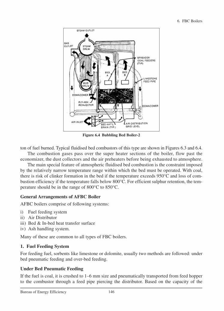
ton of fuel burned. Typical fluidised bed combustors of this type are shown in Figures 6.3 and 6.4.The combustion gases pass over the super heater sections of the boiler, flow past the
economizer, the dust collectors and the air preheaters before being exhausted to atmosphere.The main special feature of atmospheric fluidised bed combustion is the constraint imposed
by the relatively narrow temperature range within which the bed must be operated. With coal,there is risk of clinker formation in the bed if the temperature exceeds 950°C and loss of com-bustion efficiency if the temperature falls below 800°C. For efficient sulphur retention, the tem-perature should be in the range of 800°C to 850°C.
General Arrangements of AFBC Boiler
AFBC boilers comprise of following systems:
i) Fuel feeding systemii) Air Distributoriii) Bed & In-bed heat transfer surfaceiv) Ash handling system.
Many of these are common to all types of FBC boilers.
1. Fuel Feeding System
For feeding fuel, sorbents like limestone or dolomite, usually two methods are followed: underbed pneumatic feeding and over-bed feeding.
Under Bed Pneumatic Feeding
If the fuel is coal, it is crushed to 1–6 mm size and pneumatically transported from feed hopperto the combustor through a feed pipe piercing the distributor. Based on the capacity of the
6. FBC Boilers
146Bureau of Energy Efficiency
Figure 6.4 Bubbling Bed Boiler-2
Ch-06.qxd 2/23/2005 11:24 AM Page 146

boiler, the number of feed points is increased, as it is necessary to distribute the fuel into thebed uniformly.
Over-Bed Feeding
The crushed coal, 6–10 mm size is conveyed from coal bunker to a spreader by a screwconveyor. The spreader distributes the coal over the surface of the bed uniformly. This type offuel feeding system accepts over size fuel also and eliminates transport lines, when comparedto under-bed feeding system.
2. Air Distributor
The purpose of the distributor is to introduce the fluidizing air evenly through the bed crosssection thereby keeping the solid particles in constant motion, and preventing the formation ofdefluidization zones within the bed. The distributor, which forms the furnace floor, is normallyconstructed from metal plate with a number of perforations in a definite geometric pattern. Theperforations may be located in simple nozzles or nozzles with bubble caps, which serve toprevent solid particles from flowing back into the space below the distributor.
The distributor plate is protected from high temperature of the furnace by:
i) Refractory Liningii) A Static Layer of the Bed Material or iii) Water Cooled Tubes.
3. Bed & In-Bed Heat Transfer Surface:
a) Bed
The bed material can be sand, ash, crushed refractory or limestone, with an average size ofabout 1 mm. Depending on the bed height these are of two types: shallow bed and deep bed.
At the same fluidizing velocity, the two ends fluidise differently, thus affecting the heattransfer to an immersed heat transfer surfaces. A shallow bed offers a lower bed resistance andhence a lower pressure drop and lower fan power consumption. In the case of deep bed, thepressure drop is more and this increases the effective gas velocity and also the fan power.
b) In-Bed Heat Transfer Surface
In a fluidised in-bed heat transfer process, it is necessary to transfer heat between the bedmaterial and an immersed surface, which could be that of a tube bundle, or a coil. The heatexchanger orientation can be horizontal, vertical or inclined. From a pressure drop point ofview, a horizontal bundle in a shallow bed is more attractive than a vertical bundle in a deepbed. Also, the heat transfer in the bed depends on number of parameters like (i) bed pressure(ii) bed temperature (iii) superficial gas velocity (iv) particle size (v) Heat exchanger designand (vi) gas distributor plate design.
4. Ash Handling System
a) Bottom Ash Removal
In the FBC boilers, the bottom ash constitutes roughly 30 – 40 % of the total ash, the restbeing the fly ash. The bed ash is removed by continuous over flow to maintain bed height
6. FBC Boilers
147Bureau of Energy Efficiency
Ch-06.qxd 2/23/2005 11:24 AM Page 147

and also by intermittent flow from the bottom to remove over size particles, avoid accumu-lation and consequent defluidization. While firing high ash coal such as washery rejects, thebed ash overflow drain quantity is considerable so special care has to be taken.
b) Fly Ash Removal
The amount of fly ash to be handled in FBC boiler is relatively very high, when compared toconventional boilers. This is due to elutriation of particles at high velocities. Fly ash carriedaway by the flue gas is removed in number of stages; firstly in convection section, then fromthe bottom of air preheater/economizer and finally a major portion is removed in dustcollectors.
The types of dust collectors used are cyclone, bagfilters, electrostatic precipitators (ESP’s)or some combination of all of these. To increase the combustion efficiency, recycling of fly ashis practiced in some of the units.
6.3.2 Circulating Fluidised Bed Combustion (CFBC)
Circulating Fluidised Bed Combustion (CFBC) technology has evolved from conventionalbubbling bed combustion as a means to overcome some of the drawbacks associated withconventional bubbling bed combustion (see Figure 6.5).
This CFBC technology utilizes the fluidised bed principle in which crushed (6 –12 mmsize) fuel and limestone are injected into the furnace or combustor. The particles are suspendedin a stream of upwardly flowing air (60-70% of the total air), which enters the bottom of thefurnace through air distribution nozzles. The fluidising velocity in circulating beds ranges from3.7 to 9 m/sec. The balance of combustion air is admitted above the bottom of the furnace assecondary air. The combustion takes place at 840-900 °C, and the fine particles (<450 microns)are elutriated out of the furnace with flue gas velocity of 4–6 m/s. The particles are thencollected by the solids separators and circulated back into the furnace. Solid recycle is about 50to 100 kg per kg of fuel burnt.
There are no steam generation tubes immersed in the bed. The circulating bed is designedto move a lot more solids out of the furnace area and to achieve most of the heat transfer out-side the combustion zone – convection section, water walls, and at the exit of the riser. Somecirculating bed units even have external heat exchanges.
The particles circulation provides efficient heat transfer to the furnace walls and longer res-idence time for carbon and limestone utilisation. Similar to Pulverized Coal (PC) firing, thecontrolling parameters in the CFB combustion process are temperature, residence time andturbulence.
For large units, the taller furnace characteristics of CFBC boiler offers better spaceutilisation, greater fuel particle and sorbent residence time for efficient combustion and SO2
capture, and easier application of staged combustion techniques for NOx control than AFBCgenerators. CFBC boilers are said to achieve better calcium to sulphur utilisation – 1.5 to 1 vs.3.2 to 1 for the AFBC boilers, although the furnace temperatures are almost the same.
CFBC boilers are generally claimed to be more economical than AFBC boilers for industrialapplication requiring more than 75 - 100 T/hr of steam.
CFBC requires huge mechanical cyclones to capture and recycle the large amount of bedmaterial, which requires a tall boiler.
6. FBC Boilers
148Bureau of Energy Efficiency
Ch-06.qxd 2/23/2005 11:24 AM Page 148
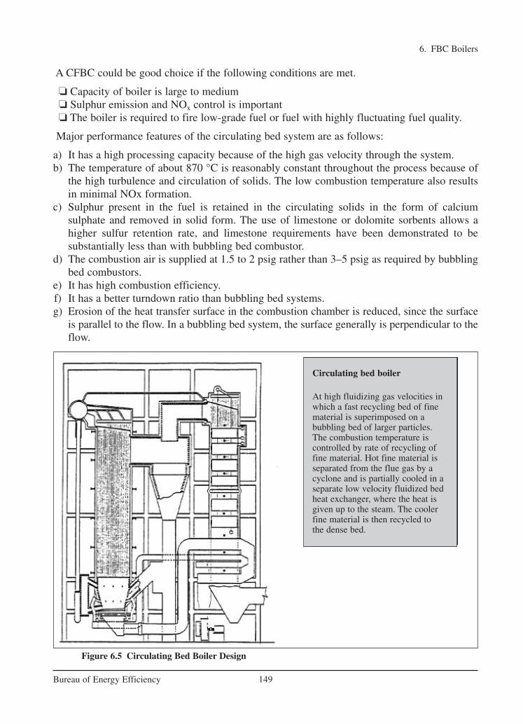
A CFBC could be good choice if the following conditions are met.
� Capacity of boiler is large to medium� Sulphur emission and NOx control is important� The boiler is required to fire low-grade fuel or fuel with highly fluctuating fuel quality.
Major performance features of the circulating bed system are as follows:
a) It has a high processing capacity because of the high gas velocity through the system. b) The temperature of about 870 °C is reasonably constant throughout the process because of
the high turbulence and circulation of solids. The low combustion temperature also resultsin minimal NOx formation.
c) Sulphur present in the fuel is retained in the circulating solids in the form of calciumsulphate and removed in solid form. The use of limestone or dolomite sorbents allows ahigher sulfur retention rate, and limestone requirements have been demonstrated to be substantially less than with bubbling bed combustor.
d) The combustion air is supplied at 1.5 to 2 psig rather than 3–5 psig as required by bubblingbed combustors.
e) It has high combustion efficiency.f) It has a better turndown ratio than bubbling bed systems.g) Erosion of the heat transfer surface in the combustion chamber is reduced, since the surface
is parallel to the flow. In a bubbling bed system, the surface generally is perpendicular to theflow.
6. FBC Boilers
149Bureau of Energy Efficiency
Figure 6.5 Circulating Bed Boiler Design
Circulating bed boiler
At high fluidizing gas velocities inwhich a fast recycling bed of finematerial is superimposed on a bubbling bed of larger particles.The combustion temperature is controlled by rate of recycling offine material. Hot fine material isseparated from the flue gas by acyclone and is partially cooled in aseparate low velocity fluidized bedheat exchanger, where the heat isgiven up to the steam. The coolerfine material is then recycled to the dense bed.
Ch-06.qxd 2/23/2005 11:24 AM Page 149

At elevated pressure, the potential reduction in boiler size is considerable due to increasedamount of combustion in pressurized mode and high heat flux through in-bed tubes. Acomparison of size of a typical 250 MW PFBC boiler versus conventional pulverized fuel-firedboiler is shown in the Figure 6.7.
6.3.3 Pressurised Fluid Bed Combustion
Pressurised Fluidised Bed Combustion (PFBC) is a variation of fluid bed technology that ismeant for large-scale coal burning applications. In PFBC, the bed vessel is operated at pressureupto 16 ata ( 16 kg/cm2).
The off-gas from the fluidised bed combustor drives the gas turbine. The steam turbine isdriven by steam raised in tubes immersed in the fluidised bed. The condensate from the steamturbine is pre-heated using waste heat from gas turbine exhaust and is then taken as feed waterfor steam generation.
The PFBC system can be used for cogeneration or combined cycle power generation. Bycombining the gas and steam turbines in this way, electricity is generated more efficientlythan in conventional system. The overall conversion efficiency is higher by 5% to 8%. .
(Refer Figure 6.6).
6. FBC Boilers
150Bureau of Energy Efficiency
Figure 6.6 PFBC Boiler for Cogeneration
Ch-06.qxd 2/23/2005 11:24 AM Page 150
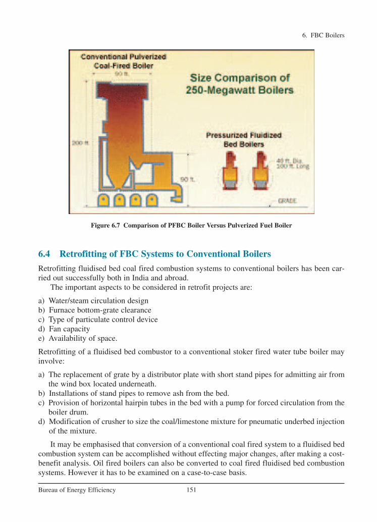
6. FBC Boilers
151Bureau of Energy Efficiency
Figure 6.7 Comparison of PFBC Boiler Versus Pulverized Fuel Boiler
6.4 Retrofitting of FBC Systems to Conventional Boilers
Retrofitting fluidised bed coal fired combustion systems to conventional boilers has been car-ried out successfully both in India and abroad.
The important aspects to be considered in retrofit projects are:
a) Water/steam circulation designb) Furnace bottom-grate clearancec) Type of particulate control deviced) Fan capacitye) Availability of space.
Retrofitting of a fluidised bed combustor to a conventional stoker fired water tube boiler mayinvolve:
a) The replacement of grate by a distributor plate with short stand pipes for admitting air fromthe wind box located underneath.
b) Installations of stand pipes to remove ash from the bed.c) Provision of horizontal hairpin tubes in the bed with a pump for forced circulation from the
boiler drum.d) Modification of crusher to size the coal/limestone mixture for pneumatic underbed injection
of the mixture.
It may be emphasised that conversion of a conventional coal fired system to a fluidised bedcombustion system can be accomplished without effecting major changes, after making a cost-benefit analysis. Oil fired boilers can also be converted to coal fired fluidised bed combustionsystems. However it has to be examined on a case-to-case basis.
Ch-06.qxd 2/23/2005 11:24 AM Page 151

6.5 Advantages of Fluidised Bed Combustion Boilers
1. High Efficiency
FBC boilers can burn fuel with a combustion efficiency of over 95% irrespective of ash con-tent. FBC boilers can operate with overall efficiency of 84% (plus or minus 2%).
2. Reduction in Boiler Size
High heat transfer rate over a small heat transfer area immersed in the bed result in overallsize reduction of the boiler.
3. Fuel Flexibility
FBC boilers can be operated efficiently with a variety of fuels. Even fuels like flotationslimes, washer rejects, agro waste can be burnt efficiently. These can be fed either inde-pendently or in combination with coal into the same furnace.
4. Ability to Burn Low Grade Fuel
FBC boilers would give the rated output even with inferior quality fuel. The boilers can firecoals with ash content as high as 62% and having calorific value as low as 2,500 kCal/kg.Even carbon content of only 1% by weight can sustain the fluidised bed combustion.
5. Ability to Burn Fines
Coal containing fines below 6 mm can be burnt efficiently in FBC boiler, which is very difficult to achieve in conventional firing system.
6. Pollution Control
SO2 formation can be greatly minimised by addition of limestone or dolomite for high sul-phur coals. 3% limestone is required for every 1% sulphur in the coal feed. Low combus-tion temperature eliminates NOx formation.
7. Low Corrosion and Erosion
The corrosion and erosion effects are less due to lower combustion temperature, softness ofash and low particle velocity (of the order of 1 m/sec).
8. Easier Ash Removal – No Clinker Formation
Since the temperature of the furnace is in the range of 750 – 900 °C in FBC boilers, evencoal of low ash fusion temperature can be burnt without clinker formation. Ash removal iseasier as the ash flows like liquid from the combustion chamber. Hence less manpower isrequired for ash handling.
9. Less Excess Air – Higher CO2 in Flue Gas
The CO2 in the flue gases will be of the order of 14 – 15% at full load. Hence, the FBC -boiler can operate at low excess air - only 20 - 25%.
10. Simple Operation, Quick Start-Up
High turbulence of the bed facilitates quick start up and shut down. Full automation of startup and operation using reliable equipment is possible.
6. FBC Boilers
152Bureau of Energy Efficiency
Ch-06.qxd 2/23/2005 11:24 AM Page 152

11. Fast Response to Load Fluctuations
Inherent high thermal storage characteristics can easily absorb fluctuation in fuel feed rates.Response to changing load is comparable to that of oil fired boilers.
12. No Slagging in the Furnace–No Soot Blowing
In FBC boilers, volatilisation of alkali components in ash does not take place and the ash isnon sticky. This means that there is no slagging or soot blowing.
13 Provisions of Automatic Coal and Ash Handling System
Automatic systems for coal and ash handling can be incorporated, making the plant easy tooperate comparable to oil or gas fired installation.
14 Provision of Automatic Ignition System
Control systems using micro-processors and automatic ignition equipment give excellentcontrol with minimum manual supervision.
15 High Reliability
The absence of moving parts in the combustion zone results in a high degree of reliabilityand low maintenance costs.
16 Reduced Maintenance
Routine overhauls are infrequent and high efficiency is maintained for long periods.
17 Quick Responses to Changing Demand
A fluidised bed combustor can respond to changing heat demands more easily than stokerfired systems. This makes it very suitable for applications such as thermal fluid heaters,which require rapid responses.
18 High Efficiency of Power Generation
By operating the fluidised bed at elevated pressure, it can be used to generate hot pressur-ized gases to power a gas turbine. This can be combined with a conventional steam turbineto improve the efficiency of electricity generation and give a potential fuel savings of atleast 4%.
6. FBC Boilers
153Bureau of Energy Efficiency
Ch-06.qxd 2/23/2005 11:24 AM Page 153
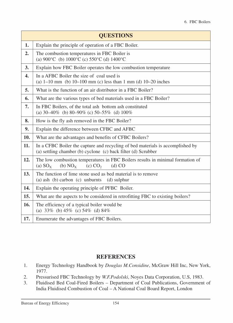
6. FBC Boilers
154Bureau of Energy Efficiency
QUESTIONS
1. Explain the principle of operation of a FBC Boiler.
2. The combustion temperatures in FBC Boiler is(a) 900°C (b) 1000°C (c) 550°C (d) 1400°C
3. Explain how FBC Boiler operates the low combustion temperature
4. In a AFBC Boiler the size of coal used is (a) 1–10 mm (b) 10–100 mm (c) less than 1 mm (d) 10–20 inches
5. What is the function of an air distributor in a FBC Boiler?
6. What are the various types of bed materials used in a FBC Boiler?
7. In FBC Boilers, of the total ash bottom ash constituted (a) 30–40% (b) 80–90% (c) 50–55% (d) 100%
8. How is the fly ash removed in the FBC Boiler?
9. Explain the difference between CFBC and AFBC
10. What are the advantages and benefits of CFBC Boilers?
11. In a CFBC Boiler the capture and recycling of bed materials is accomplished by (a) settling chamber (b) cyclone (c) back filter (d) Scrubber
12. The low combustion temperatures in FBC Boilers results in minimal formation of (a) SOX (b) NOX (c) CO2 (d) CO
13. The function of lime stone used as bed material is to remove (a) ash (b) carbon (c) unburnts (d) sulphur
14. Explain the operating principle of PFBC Boiler.
15. What are the aspects to be considered in retrofitting FBC to existing boilers?
16. The efficiency of a typical boiler would be (a) 33% (b) 45% (c) 54% (d) 84%
17. Enumerate the advantages of FBC Boilers.
REFERENCES1. Energy Technology Handbook by Douglas M.Considine, McGraw Hill Inc, New York,
1977.2. Pressurised FBC Technology by W.F.Podolski, Noyes Data Corporation, U.S, 1983.3. Fluidised Bed Coal-Fired Boilers – Department of Coal Publications, Government of
India Fluidised Combustion of Coal – A National Coal Board Report, London
Ch-06.qxd 2/23/2005 11:24 AM Page 154

7. COGENERATION
155Bureau of Energy Efficiency
Syllabus
Cogeneration: Definition, Need, Application, Advantages, Classification, Saving potentials
7.1 Need for Cogeneration
Thermal power plants are a major source of electricity supply in India. The conventionalmethod of power generation and supply to the customer is wasteful in the sense that only abouta third of the primary energy fed into the power plant is actually made available to the user inthe form of electricity (Figure 7.1). In conventional power plant, efficiency is only 35% andremaining 65% of energy is lost. The major source of loss in the conversion process is the heatrejected to the surrounding water or air due to the inherent constraints of the different thermodynamic cycles employed in power generation. Also further losses of around 10–15%are associated with the transmission and distribution of electricity in the electrical grid.
7.2 Principle of Cogeneration
Cogeneration or Combined Heat and Power (CHP) is defined as the sequential generation oftwo different forms of useful energy from a single primary energy source, typically mechanicalenergy and thermal energy. Mechanical energy may be used either to drive an alternator for pro-ducing electricity, or rotating equipment such as motor, compressor, pump or fan for delivering
Figure 7.1 BALANCE IN TYPICAL COAL FIRED POWER STATION For an Input Energy of 100 Giga Joules (GJ)
Ch-07.qxd 2/23/2005 11:24 AM Page 155
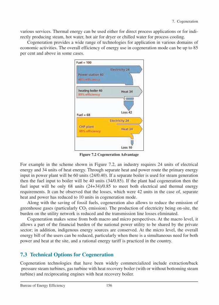
various services. Thermal energy can be used either for direct process applications or for indi-rectly producing steam, hot water, hot air for dryer or chilled water for process cooling.
Cogeneration provides a wide range of technologies for application in various domains ofeconomic activities. The overall efficiency of energy use in cogeneration mode can be up to 85per cent and above in some cases.
For example in the scheme shown in Figure 7.2, an industry requires 24 units of electricalenergy and 34 units of heat energy. Through separate heat and power route the primary energyinput in power plant will be 60 units (24/0.40). If a separate boiler is used for steam generationthen the fuel input to boiler will be 40 units (34/0.85). If the plant had cogeneration then thefuel input will be only 68 units (24+34)/0.85 to meet both electrical and thermal energy requirements. It can be observed that the losses, which were 42 units in the case of, separateheat and power has reduced to 10 units in cogeneration mode.
Along with the saving of fossil fuels, cogeneration also allows to reduce the emission ofgreenhouse gases (particularly CO2 emission). The production of electricity being on-site, theburden on the utility network is reduced and the transmission line losses eliminated.
Cogeneration makes sense from both macro and micro perspectives. At the macro level, itallows a part of the financial burden of the national power utility to be shared by the private sector; in addition, indigenous energy sources are conserved. At the micro level, the overallenergy bill of the users can be reduced, particularly when there is a simultaneous need for bothpower and heat at the site, and a rational energy tariff is practiced in the country.
7.3 Technical Options for Cogeneration
Cogeneration technologies that have been widely commercialized include extraction/backpressure steam turbines, gas turbine with heat recovery boiler (with or without bottoming steamturbine) and reciprocating engines with heat recovery boiler.
7. Cogeneration
156Bureau of Energy Efficiency
Figure 7.2 Cogeneration Advantage
Ch-07.qxd 2/23/2005 11:24 AM Page 156

7.3.1 Steam Turbine Cogeneration systems
The two types of steam turbines most widely used are the backpressure and the extraction-Another variation of the steam turbine topping cycle cogeneration system is the extraction-backpressure turbine that can be employed where the end-user needs thermal energy at two different temperature levels. The full-condensing steam turbines are usually incorporated atsites where heat rejected from the process is used to generate power.
The specific advantage of using steam turbines in comparison with the other prime moversis the option for using a wide variety of conventional as well as alternative fuels such as coal,natural gas, fuel oil and biomass. The power generation efficiency of the emand for electricityis greater than one MW up to a few hundreds of MW. Due to the system inertia, their operationis not suitable for sites with intermittent energy demand.
7.3.2 Gasturbine Cogeneration Systems
Gas turbine cogeneration systems can produce all or a part of the energy requirement of the site,and the energy released at high temperature in the exhaust stack can be recovered for variousheating and cooling applications (see Figure 7.4). Though natural gas is most commonly used,other fuels such as light fuel oil or diesel can also be employed. The typical range of gas turbines varies from a fraction of a MW to around 100 MW.
Gas turbine cogeneration has probably experienced the most rapid development in therecent years due to the greater availability of natural gas, rapid progress in the technology, significant reduction in installation costs, and better environmental performance. Furthermore,the gestation period for developing a project is shorter and the equipment can be delivered in amodular manner. Gas turbine has a short start-up time and provides the flexibility of intermit-tent operation. Though it has a low heat to power conversion efficiency, more heat can be recovered at higher temperatures. If the heat output is less than that required by the user, it ispossible to have supplementary natural gas firing by mixing additional fuel to the oxygen-richexhaust gas to boost the thermal output more efficiently.
7. Cogeneration
157Bureau of Energy Efficiency
Figure 7.3 Schematic Diagrams of Steam Turbine Cogeneration Systems
Ch-07.qxd 2/23/2005 11:24 AM Page 157

On the other hand, if more power is required at the site, it is possible to adopt a combined cyclethat is a combination of gas turbine and steam turbine cogeneration. Steam generated from theexhaust gas of the gas turbine is passed through a backpressure or extraction-condensing steamturbine to generate additional power. The exhaust or the extracted steam from the steam turbineprovides the required thermal energy.
7.3.3 Reciprocating Engine Cogeneration Systems
Also known as internal combustion (I. C.) engines, these cogeneration systems have high powergeneration efficiencies in comparison with other prime movers. There are two sources of heatfor recovery: exhaust gas at high temperature and engine jacket cooling water system at lowtemperature (see Figure 7.5). As heat recovery can be quite efficient for smaller systems, thesesystems are more popular with smaller energy consuming facilities, particularly those having agreater need for electricity than thermal energy and where the quality of heat required is nothigh, e.g. low pressure steam or hot water.
7. Cogeneration
158Bureau of Energy Efficiency
Figure 7.4 Schematic Diagram of Gas Turbine Cogeneration
Figure 7.5 Schematic Diagram of Reciprocating Engine Cogeneration
FlueGases
(–500°C)
ExhaustHeat(–150°C)
Water
Boiler
Fuel Air
Gas Turbine
Generator
Electricity
Steam
Ch-07.qxd 2/23/2005 11:24 AM Page 158

A gas turbine or diesel engineproducing electrical or mechanicalpower followed by a heat recoveryboiler to create steam to drive a secondary steam turbine. This is calleda combined-cycle topping system.
The second type of system burns fuel(any type) to produce high-pressuresteam that then passes through a steamturbine to produce power with theexhaust provides low-pressure processsteam. This is a steam-turbine toppingsystem.
A third type employs heat recoveryfrom an engine exhaust and/or jacketcooling system flowing to a heatrecovery boiler, where it is convertedto process steam / hot water for furtheruse.
TABLE 7.1 TYPES OF TOPPING CYCLES
Though diesel has been the most common fuel in the past, the prime movers can also operate with heavy fuel oil or natural gas. These machines are ideal for intermittent operationand their performance is not as sensitive to the changes in ambient temperatures as the gas tur-bines. Though the initial investment on these machines is low, their operating and maintenancecosts are high due to high wear and tear.
7.4 Classification of Cogeneration Systems
Cogeneration systems are normally classified according to the sequence of energy use and theoperating schemes adopted.
A cogeneration system can be classified as either a topping or a bottoming cycle on the basisof the sequence of energy use. In a topping cycle, the fuel supplied is used to first producepower and then thermal energy, which is the by-product of the cycle and is used to satisfyprocess heat or other thermal requirements. Topping cycle cogeneration is widely used and isthe most popular method of cogeneration.
Topping Cycle
The four types of topping cycle cogeneration systems are briefly explained in Table 7.1.
7. Cogeneration
159Bureau of Energy Efficiency
Ch-07.qxd 2/23/2005 11:24 AM Page 159
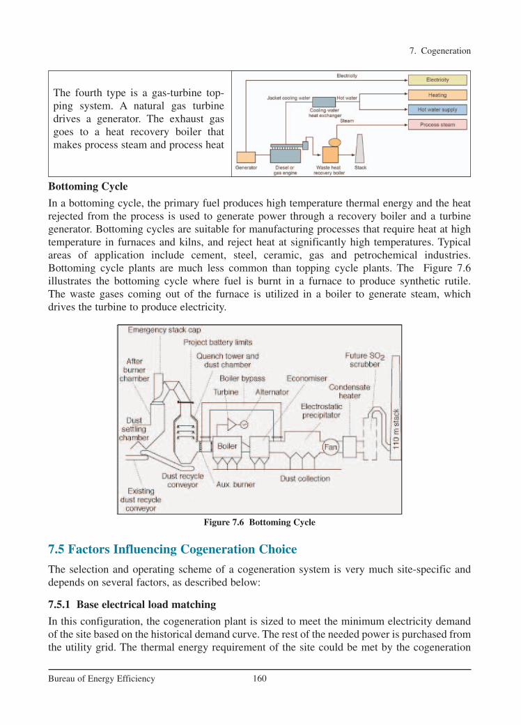
The fourth type is a gas-turbine top-ping system. A natural gas turbine drives a generator. The exhaust gasgoes to a heat recovery boiler thatmakes process steam and process heat
Bottoming Cycle
In a bottoming cycle, the primary fuel produces high temperature thermal energy and the heatrejected from the process is used to generate power through a recovery boiler and a turbine generator. Bottoming cycles are suitable for manufacturing processes that require heat at hightemperature in furnaces and kilns, and reject heat at significantly high temperatures. Typicalareas of application include cement, steel, ceramic, gas and petrochemical industries.Bottoming cycle plants are much less common than topping cycle plants. The Figure 7.6 illustrates the bottoming cycle where fuel is burnt in a furnace to produce synthetic rutile. The waste gases coming out of the furnace is utilized in a boiler to generate steam, which drives the turbine to produce electricity.
7.5 Factors Influencing Cogeneration Choice
The selection and operating scheme of a cogeneration system is very much site-specific anddepends on several factors, as described below:
7.5.1 Base electrical load matching
In this configuration, the cogeneration plant is sized to meet the minimum electricity demandof the site based on the historical demand curve. The rest of the needed power is purchased fromthe utility grid. The thermal energy requirement of the site could be met by the cogeneration
7. Cogeneration
160Bureau of Energy Efficiency
Figure 7.6 Bottoming Cycle
Ch-07.qxd 2/23/2005 11:24 AM Page 160

system alone or by additional boilers. If the thermal energy generated with the base electricalload exceeds the plant’s demand and if the situation permits, excess thermal energy can beexported to neighbouring customers.
7.5.2 Base Thermal Load Matching
Here, the cogeneration system is sized to supply the minimum thermal energy requirement ofthe site. Stand-by boilers or burners are operated during periods when the demand for heat ishigher. The prime mover installed operates at full load at all times. If the electricity demand ofthe site exceeds that which can be provided by the prime mover, then the remaining amount canbe purchased from the grid. Likewise, if local laws permit, the excess electricity can be sold tothe power utility.
7.5.3 Electrical Load Matching
In this operating scheme, the facility is totally independent of the power utility grid. All thepower requirements of the site, including the reserves needed during scheduled and unsched-uled maintenance, are to be taken into account while sizing the system. This is also referred to as a “stand-alone” system. If the thermal energy demand of the site is higher than that generated by the cogeneration system, auxiliary boilers are used. On the other hand, when thethermal energy demand is low, some thermal energy is wasted. If there is a possibility, excessthermal energy can be exported to neighbouring facilities.
7.5.4 Thermal Load Matching
The cogeneration system is designed to meet the thermal energy requirement of the site at anytime. The prime movers are operated following the thermal demand. During the period whenthe electricity demand exceeds the generation capacity, the deficit can be compensated bypower purchased from the grid. Similarly, if the local legislation permits, electricity producedin excess at any time may be sold to the utility.
7.6 Important Technical Parameters for Cogeneration
While selecting cogeneration systems, one should consider some important technical parameters that assist in defining the type and operating scheme of different alternative cogeneration systems to be selected.
7.6.1 Heat-to-Power Ratio
Heat-to-power ratio is one of the most important technical parameters influencing the selectionof the type of cogeneration system. The heat-to-power ratio of a facility should match with thecharacteristics of the cogeneration system to be installed.
It is defined as the ratio of thermal energy to electricity required by the energy consumingfacility. Though it can be expressed in different units such as Btu/kWh, kCal/kWh, lb./hr/kW,etc., here it is presented on the basis of the same energy unit (kW).
Basic heat-to-power ratios of the different cogeneration systems are shown in Table 7.2along with some technical parameters. The steam turbine cogeneration system can offer a largerange of heat-to-power ratios.
7. Cogeneration
161Bureau of Energy Efficiency
Ch-07.qxd 2/23/2005 11:24 AM Page 161

Cogeneration uses a single process to generate both electricity and usable heat or cooling. The proportions of heat and power needed (heat: power ratio) vary from site to site, so the typeof plant must be selected carefully and appropriate operating schemes must be established tomatch demands as closely as possible. The plant may therefore be set up to supply part or allof the site heat and electricity loads, or an excess of either may be exported if a suitable customer is available. The following Table 7.3 shows typical heat: power ratios for certain energy intensive industries:
Cogeneration is likely to be most attractive under the following circumstances:
(a) The demand for both steam and power is balanced i.e. consistent with the range of steam: power output ratios that can be obtained from a suitable cogeneration plant.
(b) A single plant or group of plants has sufficient demand for steam and power to permit economies of scale to be achieved.
(c) Peaks and troughs in demand can be managed or, in the case of electricity, adequate backup supplies can be obtained from the utility company.
The ratio of heat to power required by a site may vary during different times of the day and seasons of the year. Importing power from the grid can make up a shortfall in electrical outputfrom the cogeneration unit and firing standby boilers can satisfy additional heat demand.
7. Cogeneration
162Bureau of Energy Efficiency
TABLE 7.2 HEAT-TO-POWER RATIOS AND OTHER PARAMETERS OF
COGENERATION SYSTEMS
Cogeneration System Heat-to-power Power output Overall ratio (as percent of efficiency
(kWth/kWe) fuel input) per centBack-pressure steam turbine 4.0-14.3 14-28 84-92
Extraction-condensing steam turbine 2.0-10.0 22-40 60-80
Gas turbine 1.3-2.0 24-35 70-85
Combined cycle 1.0-1.7 34-40 69-83
Reciprocating engine 1.1-2.5 33-53 75-85
TABLE 7.3 TYPICAL HEAT: POWER RATIOS FOR CERTAIN
ENERGY INTENSIVE INDUSTRIES
Industry Minimum Maximum AverageBreweries 1.1 4.5 3.1
Pharmaceuticals 1.5 2.5 2.0
Fertilizer 0.8 3.0 2.0
Food 0.8 2.5 1.2
Paper 1.5 2.5 1.9
Ch-07.qxd 2/23/2005 11:24 AM Page 162

Many large cogeneration units utilize supplementary or boost firing of the exhaust gases inorder to modify the heat: power ratio of the system to match site loads.
7.6.2 Quality of Thermal Energy Needed
The quality of thermal energy required (temperature and pressure) also determines the type ofcogeneration system. For a sugar mill needing thermal energy at about 120°C, a topping cyclecogeneration system can meet the heat demand. On the other hand, for a cement plant requiring thermal energy at about 1450°C, a bottoming cycle cogeneration system can meetboth high quality thermal energy and electricity demands of the plant.
7.6.3 Load Patterns
The heat and power demand patterns of the user affect the selection (type and size) of the cogeneration system. For instance, the load patterns of two energy consuming facilities shownin Figure 7.7 would lead to two different sizes, possibly types also, of cogeneration systems.
7. Cogeneration
163Bureau of Energy Efficiency
7.6.4 Fuels Available
Depending on the availability of fuels, some potential cogeneration systems may have to berejected. The availability of cheap fuels or waste products that can be used as fuels at a site isone of the major factors in the technical consideration because it determines the competitive-ness of the cogeneration system.
A rice mill needs mechanical power for milling and heat for paddy drying. If a cogenerationsystem were considered, the steam turbine system would be the first priority because it can usethe rice husk as the fuel, which is available as waste product from the mill.
7.6.5 System Reliability
Some energy consuming facilities require very reliable power and/or heat; for instance, a pulpand paper industry cannot operate with a prolonged unavailability of process steam. In suchinstances, the cogeneration system to be installed must be modular, i.e. it should consist of morethan one unit so that shut down of a specific unit cannot seriously affect the energy supply.
Figure 7.7 Different Heat and Power Demand Patterns in two Factories
Ch-07.qxd 2/23/2005 11:24 AM Page 163
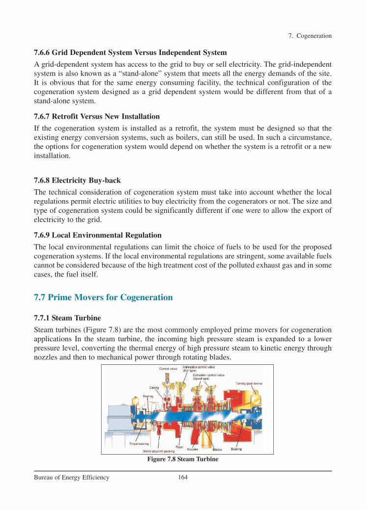
7.6.6 Grid Dependent System Versus Independent System
A grid-dependent system has access to the grid to buy or sell electricity. The grid-independentsystem is also known as a “stand-alone” system that meets all the energy demands of the site.It is obvious that for the same energy consuming facility, the technical configuration of thecogeneration system designed as a grid dependent system would be different from that of astand-alone system.
7.6.7 Retrofit Versus New Installation
If the cogeneration system is installed as a retrofit, the system must be designed so that theexisting energy conversion systems, such as boilers, can still be used. In such a circumstance,the options for cogeneration system would depend on whether the system is a retrofit or a newinstallation.
7.6.8 Electricity Buy-back
The technical consideration of cogeneration system must take into account whether the localregulations permit electric utilities to buy electricity from the cogenerators or not. The size andtype of cogeneration system could be significantly different if one were to allow the export ofelectricity to the grid.
7.6.9 Local Environmental Regulation
The local environmental regulations can limit the choice of fuels to be used for the proposedcogeneration systems. If the local environmental regulations are stringent, some available fuelscannot be considered because of the high treatment cost of the polluted exhaust gas and in somecases, the fuel itself.
7.7 Prime Movers for Cogeneration
7.7.1 Steam Turbine
Steam turbines (Figure 7.8) are the most commonly employed prime movers for cogenerationapplications In the steam turbine, the incoming high pressure steam is expanded to a lower pressure level, converting the thermal energy of high pressure steam to kinetic energy through nozzles and then to mechanical power through rotating blades.
7. Cogeneration
164Bureau of Energy Efficiency
Figure 7.8 Steam Turbine
Ch-07.qxd 2/23/2005 11:24 AM Page 164

7. Cogeneration
165Bureau of Energy Efficiency
Back Pressure turbine: In this type steam enters the turbine chamber at High Pressure andexpands to Low or Medium Pressure. Enthalpy difference is used for generating power / work.
Depending on the pressure (or temperature) levels at which process steam is required, backpressure steam turbines can have different configurations as shown in Figure 7.9.
In extraction and double extraction backpressure turbines, some amount of steam is extract-ed from the turbine after being expanded to a certain pressure level. The extracted steam meetsthe heat demands at pressure levels higher than the exhaust pressure of the steam turbine.
The efficiency of a backpressure steam turbine cogeneration system is the highest. In caseswhere 100 per cent backpressure exhaust steam is used, the only inefficiencies are gear driveand electric generator losses, and the inefficiency of steam generation. Therefore, with an efficient boiler, the overall thermal efficiency of the system could reach as much as 90 per cent.
Extraction Condensing turbine: In this type, steam entering at High / Medium Pressure isextracted at an intermediate pressure in the turbine for process use while the remaining steamcontinues to expand and condenses in a surface condenser and work is done till itreaches the Condensing pressure.(vacuum).
In Extraction cum Condensing steam turbine as shown in Figure 7.10, highPressure steam enters the turbine and passesout from the turbine chamber in stages. In atwo stage extraction cum condensing turbineMP steam and LP steam pass out to meet theprocess needs. Balance quantity condensesin the surface condenser. The Energy differ-ence is used for generating Power. This con-figuration meets the heat-power requirement
Figure 7.9 Different Configurations for Back Pressure Steam Turbines
Figure 7.10 Extraction Condensing Turbine
Ch-07.qxd 2/23/2005 11:24 AM Page 165

of the process.
The extraction condensing turbines have higher power to heat ratio in comparison with back-pressure turbines. Although condensing systems need more auxiliary equipment such as thecondenser and cooling towers, better matching of electrical power and heat demand can beobtained where electricity demand is much higher than the steam demand and the load patternsare highly fluctuating.
The overall thermal efficiency of an extraction condensing turbine cogeneration system islower than that of back pressure turbine system, basically because the exhaust heat cannot beutilized (it is normally lost in the cooling water circuit). However, extraction condensing cogen-eration systems have higher electricity generation efficiencies
7.7.2 Gas Turbine
The fuel is burnt in a pressurizedcombustion chamber using combus-tion air supplied by a compressorthat is integral with the gas turbine.In conventional Gas turbine (Figure 7.11), gases enter the turbineat a temperature range of 900 to1000°C and leave at 400 to 500°C.The very hot pressurized gases areused to turn a series of turbineblades, and the shaft on which theyare mounted, to produce mechanicalenergy. Residual energy in the formof a high flow of hot exhaust gasescan be used to meet, wholly or partly,the thermal (steam) demand of the site. Waste gases are exhausted from the turbine at 450°C to550°C, making the gas turbine particularly suitable for high-grade heat supply.
The available mechanical energy can be applied in the following ways:
• to produce electricity with a generator (most applications);
• to drive pumps, compressors, blowers, etc.
A gas turbine operates under exacting conditions of high speed and high temperature. The hotgases supplied to it must therefore be clean (i.e. free of particulates which would erode theblades) and must contain not more than minimal amounts of contaminants, which would causecorrosion under operating conditions. High-premium fuels are therefore most often used, particularly natural gas. Distillate oils such as gas oil are also suitable, and sets capable of usingboth are often installed to take advantage of cheaper interruptible gas tariffs. LPGs and Naphthaare also suitable, LPG being a possible fuel in either gaseous or liquid form.
Gas Turbine Efficiency
Turbine Efficiency is the ratio of actual work output of the turbine to the net input energy supplied in the form of fuel. For stand alone Gas Turbines, without any heat recovery system
7. Cogeneration
166Bureau of Energy Efficiency
Figure 7.11 Gas Turbine
Ch-07.qxd 2/23/2005 11:24 AM Page 166

the efficiency will be as low as 35 to 40%. This is attributed to the blade efficiency of the rotor,leakage through clearance spaces, friction, irreversible turbulence etc.
Since Exhaust gas from the Gas Turbine is high, it is possible to recover energy from thehot gas by a Heat Recovery Steam Generator and use the steam for process.
Net Turbine Efficiency
Above efficiency figures did not include the energy consumed by air compressors, fuel pumpand other auxiliaries. Air compressor alone consumes about 50 to 60% of energy generated bythe turbine. Hence net turbine efficiency, which is the actual energy output available will be lessthan what has been calculated. In most Gas Turbine plants, air compressor is an integral part ofTurbine plant.
7.7.3 Reciprocating Engine Systems
This system provides process heat or steam from engine exhaust. The engine jacket coolingwater heat exchanger and lube oil cooler may also be used to provide hot water or hot air. Thereare, however, limited applications for this.
As these engines can use only fuels like HSD, distillate, residual oils, natural gas, LPG etc.and as they are not economically better than steam/gas turbine, their use is not widespread forco-generation. One more reason for this is the engine maintenance requirement.
7. Cogeneration
167Bureau of Energy Efficiency
Figure 7.12
Ch-07.qxd 2/23/2005 11:24 AM Page 167

7.8 Typical Cogeneration Performance Parameters
The following Table 7.4 gives typical Cogeneration Performance Parameters for differentCogeneration Packages giving heat rate, overall efficiencies etc.
7.9 Relative Merits of Cogeneration Systems
The following Table 7.5 gives the advantages and disadvantages of various co-generation systems:
7. Cogeneration
168Bureau of Energy Efficiency
TABLE7.5 ADVANTAGES AND DISADVANTAGES OF VARIOUS COGENERATION SYSTEMS
Variant Advantages Disadvantages
Back pressure – High fuel efficiency rating – Little flexibility in design and operation
Steam turbine & fuel – Simple plant – More capital investmentfiring in boiler – Well-suited to low quality fuels – Low fuel efficiency
rating– High cooling water demand– More impact on environmentHigh civil const. cost due to complicated foundations
Gas turbine with – Good fuel efficiency – Moderate part load efficiencywaste heat recovery – Simple plant – Limited suitability for lowboiler – Low civil const. Cost quality fuels
– Less delivery period
TABLE 7.4 TYPICAL COGENERATION PERFORMANCE PARAMETERS
Prime Mover in Nominal Electrical Generation Efficiencies, % Cogen. Range Heat Rate Electrical Thermal Overall Package (Electrical) (kCal / kWh Conversion Recovery CogenerationSmaller 10–500 kW 2650–6300 20–32 50 74–82Reciprocating Engines
Larger 500–3000 kW 2400–3275 26–36 50 76–86Reciprocating Engines
Diesel Engines 10–3000 kW 2770–3775 23–38 50 73–88
Smaller Gas 800–10000 kW 2770–3525 24–31 50 74–81Turbines
Larger Gas 10–20 MW 2770–3275 26–31 50 78–81Turbines
Steam Turbines 10–100 MW 2520–5040 17–34 – –
Note: Adapted from Cogeneration Handbook California Energy Commission, 1982
Ch-07.qxd 2/23/2005 11:24 AM Page 168

7.10 Case Study
Economics of a Gas Turbine based co-generation System
Alternative I – Gas Turbine Based Co-generationGas turbine Parameters Capacity of gas turbine generator : 4000 kWPlant operating hours per annum : 8000 hrs.Plant load factor : 90 %Heat rate as per standard given by gas.turbine supplier : 3049.77 kCal / kWhWaste heat boiler parameters – unfired steam output : 10 TPHSteam temperature : 200 °CSteam pressure : 8.5 kg /cm2.Steam enthalpy : 676.44 kCal / Kg.Fuel used : Natural gasCalorific value – LCV : 9500 kCal/ sm3
Price of gas : Rs 3000 /1000 sm3
Capital investment for total co-generation plant : Rs. 1300 Lakhs
Cost Estimation of Power & Steam From Cogeneration Plant
1. Estimated power generation from Cogeneration : PLF × Plant Capacity × no. plant at 90% Plant Load Factor (PLF) of operation hours
(90/100)×4000×8000 288.00 × 10⁵ kWh per annum
2. Heat input to generate above units : Units (kWh) × heat rate 288 x 105 × 3049.77878333.76 × 105 kCal
3. Natural gas quantity required per annum : Heat input / Calorific value(LCV ) of natural gas
: 878333.76 x 105 / 9500
7. Cogeneration
169Bureau of Energy Efficiency
– Less impact on environment– High flexibility in operation
Combined gas & steam – Optimum fuel efficiency rating – Average to moderate turbine with waste – Low relative capital cost part-load efficiencyheat recovery boiler – Less gestation period – Limited suitability for
– Quick start up & stoppage low quality fuels– Less impact on environment– High flexibility in operation
Diesel Engine & waste – Low civil const. Cost due to block – Low overall efficiencyheat recovery foundations & least no. of auxiliaries – Limited suitability for Boiler & cooling – High Power efficiency low quality fuelswater heat exchanger – Better suitability as stand by – Availability of low
power source temperature steam– Highly maintenance prone.
Ch-07.qxd 2/23/2005 11:24 AM Page 169

92.46 × 10⁵ sm3
4. Cost of fuel per annum : Annual gas consumption.× Price92.46 × 105× Rs.3000./1000 sm3
Rs. 277.37 lakhs5. Cost of capital and operation charges/annum : Rs. 298.63. lakhs
6. Overall cost of power from cogeneration Plant : Rs. 576.00.lakhs per annum
7. Cost of power : Rs. 2.00 /kWh
Alternative-II: Electric Power from State Grid & Steam from Natural Gas Fired Boiler
Boiler Installed in Plant:Cost of electric power from state grid – average electricity : Rs. 3.00/kWhcost with demand & energy charges
Capital investment for 10 TPH, 8.5 kg/sq.cm.200)°C : Rs. 80.00 lakhNatural gas fired fire tube boiler & all auxiliaries
Estimation of cost for electric power from grid & steam from direct conventional firedboiler:
1. Cost of Power from state grid for 288 lakh kWh : Rs. 864.00 lakh per annum
2. Fuel cost for steam by separate boiler(i) Heat output in form of 10 TPH steam per annum : Steam quantity ×
Enthalphy × Operations/annum10 × 1000 × 676.44 ×
8000
=541152 × 105 kCals
(ii) Heat Input required to generate 10 TPH steam : Heat output/boilerper annum @ 90% efficiency efficiency
541152 × 105/0.90Heat Input : 601280 × 105 kCal
per annum
(iii) Natural Gas Quantity : Heat Input/Calorific
7. Cogeneration
170Bureau of Energy Efficiency
Ch-07.qxd 2/23/2005 11:24 AM Page 170

value (LCV) of natural gas601280 × 105/950063.29 × 105 sm3 per annum
(iv) Cost of fuel per annum : Annual gas consumption × price63.29 × 105× 3000 /1000 sm3
Rs. 189.88.lakhper annum
(v) Total cost for Alternative-II : Cost of grid power + fuel cost for steamRs. 864+ Rs.189.88 (lakh)Rs.1053.88 lakh per annum
Alternative I - Total cost : Rs. 576.00 lakhAlternative II - Total cost : Rs. 1053.88 lakhDifferential cost : Rs. 477.88 lakh
(Note: In case of alternative-II, there will be some additional impact on cost of steam due tocapital cost required for a separate boiler).
In the above case, Alternative 1 gas turbine based cogeneration system is economical com-pared to Alternative 2 i.e. electricity from State Grid and Steam from Natural Gas fired boiler.
7. Cogeneration
171Bureau of Energy Efficiency
Ch-07.qxd 2/23/2005 11:24 AM Page 171

7. Cogeneration
172Bureau of Energy Efficiency
QUESTIONS
1. Explain what do you mean by cogeneration.
2. Explain how cogeneration is advantageous over conventional power plant.
3. What is meant by wheeling?
4. What is meant by combined cycle cogeneration?
5. Explain the term topping cycles with examples.
6. Explain the term bottoming cycles with examples.
7. Explain the term heat-to-power ratio.
8. Explain with diagrams cogeneration systems using the back pressure turbine, extraction-condensing turbine and double extraction back pressure turbine.
9. The efficiency of which of the following is the highest (a) condensing (b) back pressure (c) extraction condensing (d) double extraction condensing
10. Explain the principle of operation of a steam turbine.
11. Explain the principle of operation of a gas turbine.
12. What are the common fuels used in gas turbines?
13. Clean fuels are used in gas turbines because (a) the operate at high speed and high temperature (b) pollution act requires it (c) combustion would be affected (d) they are inexpensive
14. The system efficiencies of gas turbine units are (a) 35 to 40% (b) 85 to 90% (c) 75 to 80% (d) 55 to 60%
15. A heat recovery steam generator is used with (a) gas turbines (b) stem turbines (c) back pressure turbines (d) condensing turbines
16. List the circumstances under which cogeneration will become attractive.
17. What are the sources of waste heat in a diesel engine?
18. Explain how you will go about an energy audit of a steam turbine based fully back pressure cogeneration system.
REFERENCES
1. Cogeneration – Training Material by NIFES, UK.2. Energy Cogeneration handbook Criteria for Central Plant Desing by George
Polimeros, Industrial Press Inc, N.Y.
www.cogen.orgwww.unescap.org/enrd/energy/co-gen/http://www.cogen.org/Downloadables/Projects/EDUCOGEN_Cogen_Guide.pdf.
Ch-07.qxd 2/23/2005 11:24 AM Page 172

8. WASTE HEAT RECOVERY
173Bureau of Energy Efficiency
SyllabusWaste Heat Recovery: Classification, Advantages and applications, Commercially viablewaste heat recovery devices, Saving potential.
8.1 Introduction
Waste heat is heat, which is generated in a process by way of fuel combustion or chemical reaction, and then “dumped” into the environment even though it could still be reused for someuseful and economic purpose. The essential quality of heat is not the amount but rather its“value”. The strategy of how to recover this heat depends in part on the temperature of the wasteheat gases and the economics involved.
Large quantity of hot flue gases is generated from Boilers, Kilns, Ovens and Furnaces.If some of this waste heat could be recovered, a considerable amount of primary fuel couldbe saved. The energy lost in waste gases cannot be fully recovered. However, much of theheat could be recovered and loss minimized by adopting following measures as outlined inthis chapter.
Heat Losses – Quality
Depending upon the type of process, waste heat can be rejected at virtually any temperaturefrom that of chilled cooling water to high temperature waste gases from an industrial fur-nace or kiln. Usually higher the temperature, higher the quality and more cost effective isthe heat recovery. In any study of waste heat recovery, it is absolutely necessary that thereshould be some use for the recovered heat. Typical examples of use would be preheating ofcombustion air, space heating, or pre-heating boiler feed water or process water. With hightemperature heat recovery, a cascade system of waste heat recovery may be practiced toensure that the maximum amount of heat is recovered at the highest potential. An exampleof this technique of waste heat recovery would be where the high temperature stage wasused for air pre-heating and the low temperature stage used for process feed water heatingor steam raising.
Heat Losses – Quantity
In any heat recovery situation it is essential to know the amount of heat recoverable and alsohow it can be used. An example of the availability of waste heat is given below:
• Heat recovery from heat treatment furnace
In a heat treatment furnace, the exhaust gases are leaving the furnace at 900 °C at the rate of2100 m3/hour. The total heat recoverable at 180oC final exhaust can be calculated as
Q = V × ρ × Cp × ∆T
Q is the heat content in kCalV is the flowrate of the substance in m3/hr
Ch-08.qxd 2/23/2005 11:25 AM Page 173

8. Waste Heat Recovery
174Bureau of Energy Efficiency
TABLE 8.1 WASTE SOURCE AND QUALITY
S.No. Source Quality
1. Heat in flue gases. The higher the temperature, the greater the potential value for heatrecovery
2. Heat in vapour streams. As above but when condensed, latent heat also recoverable.
3. Convective and radiant heat Low grade – if collected may be used for space heating or airlost from exterior of preheats.equipment
4. Heat losses in cooling water. Low grade – useful gains if heat is exchanged with incoming freshwater
5. Heat losses in providing a) High grade if it can be utilized to reduce demand for refrigeration.chilled water or in the b) Low grade if refrigeration unit used as a form of heat pump.disposal of chilled water
6. Heat stored in products Quality depends upon temperature.leaving the process
7. Heat in gaseous and liquid Poor if heavily contaminated and thus requiring alloy heat exchanger.effluents leaving process.
ρ is density of the flue gas in kg/m3
Cp is the specific heat of the substance in kCal/kg °C∆T is the temperature difference in °CCp (Specific heat of flue gas) = 0.24 kCal/kg/°C
Heat available (Q) = 2100 × 1.19 × 0.24 × ((900-180) = 4,31,827 kCal/hr
By installing a recuperator, this heat can be recovered to pre-heat the combustion air. The fuel savings would be 33% (@ 1% fuel reduction for every 22 °C reduction in temper-ature of flue gas.
8.2 Classification and Application
In considering the potential for heat recovery, it is useful to note all the possibilities, andgrade the waste heat in terms of potential value as shown in the following Table 8.1:
High Temperature Heat Recovery
The following Table 8.2 gives temperatures of waste gases from industrial process equipmentin the high temperature range. All of these results from direct fuel fired processes.
Medium Temperature Heat Recovery
The following Table 8.3 gives the temperatures of waste gases from process equipment in themedium temperature range. Most of the waste heat in this temperature range comes from theexhaust of directly fired process units.
Ch-08.qxd 2/23/2005 11:25 AM Page 174

8. Waste Heat Recovery
175Bureau of Energy Efficiency
Low Temperature Heat Recovery
The following Table 8.4 lists some heat sources in the low temperature range. In this range itis usually not practical to extract work from the source, though steam production may not becompletely excluded if there is a need for low-pressure steam. Low temperature waste heat maybe useful in a supplementary way for preheating purposes.
Types of Device Temperature, °C
Nickel refining furnace 1370 –1650
Aluminium refining furnace 650–760
Zinc refining furnace 760–1100
Copper refining furnace 760– 815
Steel heating furnaces 925–1050
Copper reverberatory furnace 900–1100
Open hearth furnace 650–700
Cement kiln (Dry process) 620– 730
Glass melting furnace 1000–1550
Hydrogen plants 650–1000
Solid waste incinerators 650–1000
Fume incinerators 650–1450
TABLE 8.2 TYPICAL WASTE HEAT TEMPERATURE AT HIGH
TEMPERATURE RANGE FROM VARIOUS SOURCES
Type of Device Temperature, °C
Steam boiler exhausts 230–480
Gas turbine exhausts 370–540
Reciprocating engine exhausts 315–600
Reciprocating engine exhausts (turbo charged) 230–370
Heat treating furnaces 425–650
Drying and baking ovens 230–600
Catalytic crackers 425–650
Annealing furnace cooling systems 425–650
TABLE 8.3 TYPICAL WASTE HEAT TEMPERATURE AT MEDIUM
TEMPERATURE RANGE FROM VARIOUS SOURCES
Ch-08.qxd 2/23/2005 11:25 AM Page 175

8.3 Benefits of Waste Heat Recovery
Benefits of 'waste heat recovery' can be broadly classified in two categories:
Direct Benefits:
Recovery of waste heat has a direct effect on the efficiency of the process. This is reflected byreduction in the utility consumption & costs, and process cost.
Indirect Benefits:
a) Reduction in pollution: A number of toxic combustible wastes such as carbon monoxidegas, sour gas, carbon black off gases, oil sludge, Acrylonitrile and other plastic chemicalsetc, releasing to atmosphere if/when burnt in the incinerators serves dual purpose i.e. recovers heat and reduces the environmental pollution levels.
b) Reduction in equipment sizes: Waste heat recovery reduces the fuel consumption, whichleads to reduction in the flue gas produced. This results in reduction in equipment sizes ofall flue gas handling equipments such as fans, stacks, ducts, burners, etc.
c) Reduction in auxiliary energy consumption: Reduction in equipment sizes gives additional benefits in the form of reduction in auxiliary energy consumption like electricityfor fans, pumps etc..
8. Waste Heat Recovery
176Bureau of Energy Efficiency
Source Temperature, °C
Process steam condensate 55–88
Cooling water from:Furnace doors 32–55
Bearings 32–88
Welding machines 32–88
Injection molding machines 32–88
Annealing furnaces 66–230
Forming dies 27–88
Air compressors 27–50
Pumps 27–88
Internal combustion engines 66–120
Air conditioning and refrigeration condensers 32–43
Liquid still condensers 32–88
Drying, baking and curing ovens 93–230
Hot processed liquids 32–232
Hot processed solids 93–232
TABLE 8.4 TYPICAL WASTE HEAT TEMPERATURE AT LOW
TEMPERATURE RANGE FROM VARIOUS SOURCES
Ch-08.qxd 2/23/2005 11:25 AM Page 176
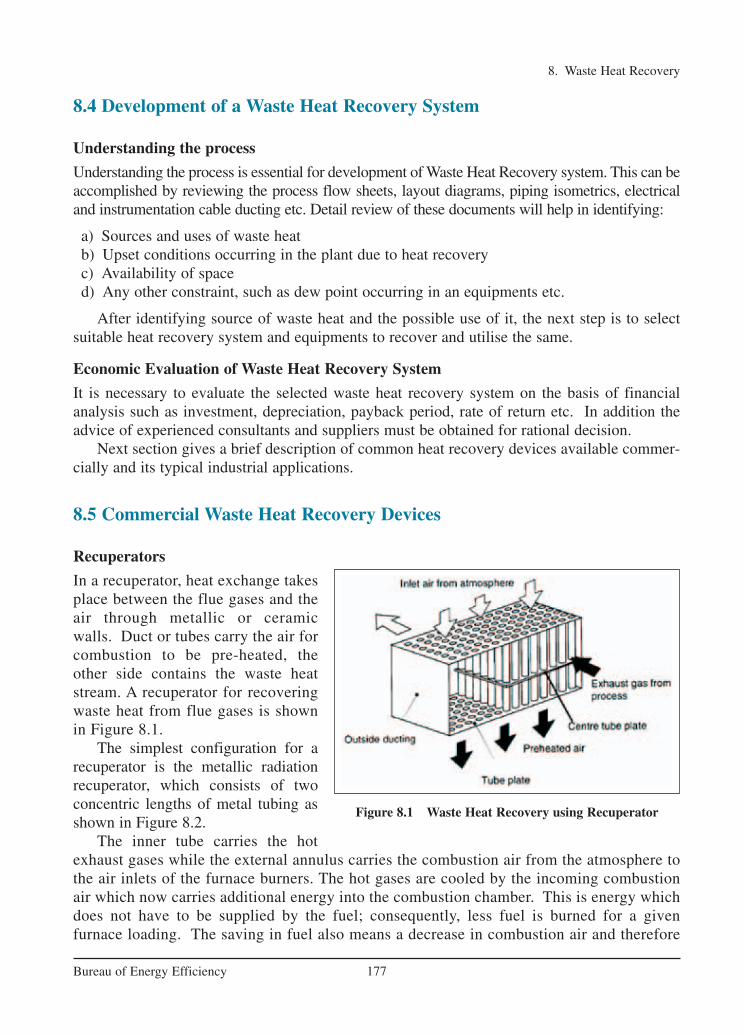
8. Waste Heat Recovery
177Bureau of Energy Efficiency
8.4 Development of a Waste Heat Recovery System
Understanding the process
Understanding the process is essential for development of Waste Heat Recovery system. This can beaccomplished by reviewing the process flow sheets, layout diagrams, piping isometrics, electricaland instrumentation cable ducting etc. Detail review of these documents will help in identifying:
a) Sources and uses of waste heatb) Upset conditions occurring in the plant due to heat recoveryc) Availability of spaced) Any other constraint, such as dew point occurring in an equipments etc.
After identifying source of waste heat and the possible use of it, the next step is to selectsuitable heat recovery system and equipments to recover and utilise the same.
Economic Evaluation of Waste Heat Recovery System
It is necessary to evaluate the selected waste heat recovery system on the basis of financialanalysis such as investment, depreciation, payback period, rate of return etc. In addition theadvice of experienced consultants and suppliers must be obtained for rational decision.
Next section gives a brief description of common heat recovery devices available commer-cially and its typical industrial applications.
8.5 Commercial Waste Heat Recovery Devices
Recuperators
In a recuperator, heat exchange takesplace between the flue gases and theair through metallic or ceramicwalls. Duct or tubes carry the air forcombustion to be pre-heated, theother side contains the waste heatstream. A recuperator for recoveringwaste heat from flue gases is shownin Figure 8.1.
The simplest configuration for arecuperator is the metallic radiationrecuperator, which consists of twoconcentric lengths of metal tubing asshown in Figure 8.2.
The inner tube carries the hotexhaust gases while the external annulus carries the combustion air from the atmosphere tothe air inlets of the furnace burners. The hot gases are cooled by the incoming combustionair which now carries additional energy into the combustion chamber. This is energy whichdoes not have to be supplied by the fuel; consequently, less fuel is burned for a given furnace loading. The saving in fuel also means a decrease in combustion air and therefore
Figure 8.1 Waste Heat Recovery using Recuperator
Ch-08.qxd 2/23/2005 11:25 AM Page 177
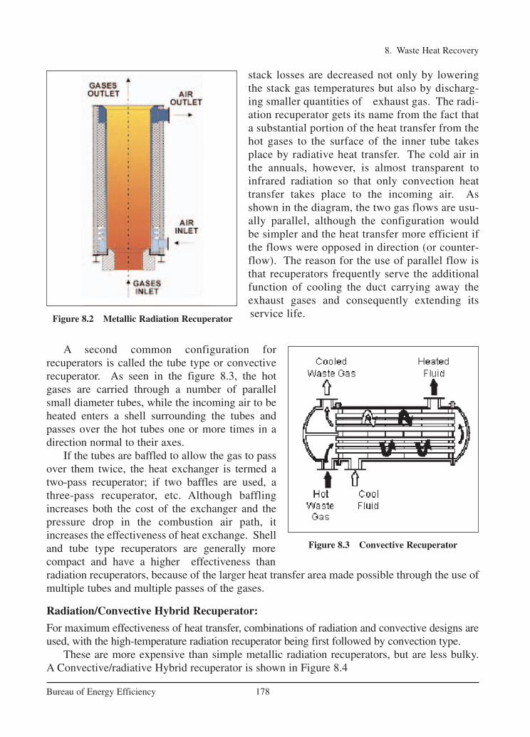
8. Waste Heat Recovery
178Bureau of Energy Efficiency
stack losses are decreased not only by loweringthe stack gas temperatures but also by discharg-ing smaller quantities of exhaust gas. The radi-ation recuperator gets its name from the fact thata substantial portion of the heat transfer from thehot gases to the surface of the inner tube takesplace by radiative heat transfer. The cold air inthe annuals, however, is almost transparent toinfrared radiation so that only convection heattransfer takes place to the incoming air. Asshown in the diagram, the two gas flows are usu-ally parallel, although the configuration wouldbe simpler and the heat transfer more efficient ifthe flows were opposed in direction (or counter-flow). The reason for the use of parallel flow isthat recuperators frequently serve the additionalfunction of cooling the duct carrying away theexhaust gases and consequently extending itsservice life.
A second common configuration for recuperators is called the tube type or convectiverecuperator. As seen in the figure 8.3, the hotgases are carried through a number of parallelsmall diameter tubes, while the incoming air to beheated enters a shell surrounding the tubes andpasses over the hot tubes one or more times in adirection normal to their axes.
If the tubes are baffled to allow the gas to passover them twice, the heat exchanger is termed atwo-pass recuperator; if two baffles are used, athree-pass recuperator, etc. Although bafflingincreases both the cost of the exchanger and thepressure drop in the combustion air path, itincreases the effectiveness of heat exchange. Shelland tube type recuperators are generally morecompact and have a higher effectiveness thanradiation recuperators, because of the larger heat transfer area made possible through the use ofmultiple tubes and multiple passes of the gases.
Radiation/Convective Hybrid Recuperator:
For maximum effectiveness of heat transfer, combinations of radiation and convective designs areused, with the high-temperature radiation recuperator being first followed by convection type.
These are more expensive than simple metallic radiation recuperators, but are less bulky. A Convective/radiative Hybrid recuperator is shown in Figure 8.4
Figure 8.2 Metallic Radiation Recuperator
Figure 8.3 Convective Recuperator
Ch-08.qxd 2/23/2005 11:25 AM Page 178

8. Waste Heat Recovery
179Bureau of Energy Efficiency
Ceramic Recuperator
The principal limitation on the heat recovery of metal recuperators is the reduced life of the linerat inlet temperatures exceeding 1100°C. In order to overcome the temperature limitations of metalrecuperators, ceramic tube recuperators have been developed whose materials allow operation on thegas side to 1550°C and on the preheated air side to 815°C on a more or less practical basis. Earlyceramic recuperators were built of tile and joined with furnace cement, and thermal cycling causedcracking of joints and rapid deterioration of the tubes. Later developments introduced various kindsof short silicon carbide tubes which can be joined by flexible seals located in the air headers.
Earlier designs had experienced leakage rates from 8 to 60 percent. The new designs are report-ed to last two years with air preheat temperatures as high as 700°C, with much lower leakage rates.
Regenerator
The Regeneration which is preferable forlarge capacities has been very widely used inglass and steel melting furnaces. Importantrelations exist between the size of the regener-ator, time between reversals, thickness ofbrick, conductivity of brick and heat storageratio of the brick.
In a regenerator, the time between thereversals is an important aspect. Long periods would mean higher thermal storageand hence higher cost. Also long periods ofreversal result in lower average temperatureof preheat and consequently reduce fueleconomy. (Refer Figure 8.5).
Accumulation of dust and slagging onthe surfaces reduce efficiency of the heattransfer as the furnace becomes old.
Figure 8.4 Convective Radiative Recuperator
Figure 8.5 Regenerator
Ch-08.qxd 2/23/2005 11:25 AM Page 179

Heat losses from the walls of the regenerator and air in leaks during the gas period and out-leaks during air period also reduces the heat transfer.
Heat Wheels
A heat wheel is finding increasing applications in low to medium temperature waste heat recov-ery systems. Figure 8.6 is a sketch illustrating the application of a heat wheel.
It is a sizable porous disk, fabricated with material having a fairly high heat capacity, whichrotates between two side-by-side ducts: one a cold gas duct, the other a hot gas duct. The axisof the disk is located parallel to, and on the partition between, the two ducts. As the disk slow-ly rotates, sensible heat (moisture that contains latent heat) is transferred to the disk by the hotair and, as the disk rotates, from the disk to the cold air. The overall efficiency of sensible heattransfer for this kind of regenerator can be as high as 85 percent. Heat wheels have been builtas large as 21 metres in diameter with air capacities up to 1130 m3 / min.
A variation of the Heat Wheel is the rotary regenerator where the matrix is in a cylinderrotating across the waste gas and air streams. The heat or energy recovery wheel is a rotary gasheat regenerator, which can transfer heat from exhaust to incoming gases.
Its main area of application is where heat exchange between large masses of air havingsmall temperature differences is required. Heating and ventilation systems and recovery of heatfrom dryer exhaust air are typical applications.
Case Example
A rotary heat regenerator was installed on a two colour printing press to recover some of theheat, which had been previously dissipated to the atmosphere, and used for drying stage of theprocess. The outlet exhaust temperature before heat recovery was often in excess of 100°C.After heat recovery the temperature was 35°C. Percentage heat recovery was 55% and paybackon the investment was estimated to be about 18 months. Cross contamination of the fresh airfrom the solvent in the exhaust gases was at a very acceptable level.
8. Waste Heat Recovery
180Bureau of Energy Efficiency
Figure 8.6 Heat Wheel
Ch-08.qxd 2/23/2005 11:25 AM Page 180

8. Waste Heat Recovery
181Bureau of Energy Efficiency
Case Example
A ceramic firm installed a heat wheel on the preheating zone of a tunnel kiln where 7500m3/hour of hot gas at 300°C was being rejected to the atmosphere. The result was that the fluegas temperature was reduced to 150°C and the fresh air drawn from the top of the kiln was pre-heated to 155°C. The burner previously used for providing the preheated air was no longerrequired. The capital cost of the equipment was recovered in less than 12 months.
Heat Pipe
A heat pipe can transfer up to 100 times more thermal energy than copper, the best known con-ductor. In other words, heat pipe is a thermal energy absorbing and transferring system and haveno moving parts and hence require minimum maintenance.
Figure 8.7 Heat Pipe
The Heat Pipe comprises of three elements - a sealed container, a capillary wick structureand a working fluid. The capillary wick structure is integrally fabricated into the interior sur-face of the container tube and sealed under vacuum. Thermal energy applied to the externalsurface of the heat pipe is in equilibrium with its own vapour as the container tube is sealedunder vacuum. Thermal energy applied to the external surface of the heat pipe causes the work-ing fluid near the surface to evaporate instantaneously. Vapour thus formed absorbs the latentheat of vapourisation and this part of the heat pipe becomes an evaporator region. The vapourthen travels to the other end the pipe where the thermal energy is removed causing the vapourto condense into liquid again, thereby giving up the latent heat of the condensation. This partof the heat pipe works as the condenser region. The condensed liquid then flows back to theevaporated region. A figure of Heat pipe is shown in Figure 8.7
Performance and Advantage
The heat pipe exchanger (HPHE) is a lightweight compact heat recovery system. It virtuallydoes not need mechanical maintenance, as there are no moving parts to wear out. It does notneed input power for its operation and is free from cooling water and lubrication systems. Italso lowers the fan horsepower requirement and increases the overall thermal efficiency of thesystem. The heat pipe heat recovery systems are capable of operating at 315°C. with 60% to80% heat recovery capability.
Ch-08.qxd 2/23/2005 11:25 AM Page 181

8. Waste Heat Recovery
182Bureau of Energy Efficiency
Typical Application
The heat pipes are used in following industrial applications:
a. Process to Space Heating: The heat pipe heat exchanger transfers the thermal energyfrom process exhaust for building heating. The preheated air can be blended if required.The requirement of additional heating equipment to deliver heated make up air is dras-tically reduced or eliminated.
b. Process to Process: The heat pipe heat exchangers recover waste thermal energy fromthe process exhaust and transfer this energy to the incoming process air. The incomingair thus become warm and can be used for the same process/other processes and reducesprocess energy consumption.
c. HVAC Applications:
Cooling: Heat pipe heat exchangers precools the building make up air in summer andthus reduces the total tons of refrigeration, apart from the operational saving of the cool-ing system. Thermal energy is supply recovered from the cool exhaust and transferredto the hot supply make up air.
Heating: The above process is reversed during winter to preheat the make up air.
The other applications in industries are:
• Preheating of boiler combustion air• Recovery of Waste heat from furnaces• Reheating of fresh air for hot air driers• Recovery of waste heat from catalytic deodorizing equipment• Reuse of Furnace waste heat as heat source for other oven• Cooling of closed rooms with outside air • Preheating of boiler feed water with waste heat recovery from flue gases in the heat pipe
economizers.• Drying, curing and baking ovens• Waste steam reclamation • Brick kilns (secondary recovery)• Reverberatory furnaces (secondary recovery)• Heating, ventilating and air-conditioning systems
Case Example
Savings in Hospital Cooling Systems
Volume 140 m3/min ExhaustRecovered heat 28225 kCal/hrPlant capacity reduction 9.33 Tons of RefrigerationElectricity cost (operation) Rs. 268/Million kCal (based on 0.8 kW/TR)Plant capacity reduction cost (Capital) Rs.12,000/TRCapital cost savings Rs. 1,12,000/-Payback period 16570 hours
Ch-08.qxd 2/23/2005 11:25 AM Page 182

Economiser
In case of boiler system, economizer can beprovided to utilize the flue gas heat for pre-heating the boiler feed water. On the otherhand, in an air pre-heater, the waste heat isused to heat combustion air. In both thecases, there is a corresponding reduction inthe fuel requirements of the boiler. An economizer is shown in Figure 8.8.
For every 22°C reduction in flue gastemperature by passing through aneconomiser or a pre-heater, there is 1%saving of fuel in the boiler. In otherwords, for every 6°C rise in feed watertemperature through an economiser, or20°C rise in combustion air temperature through an air pre-heater, there is 1% saving of fuel inthe boiler.
Shell and Tube Heat Exchanger:
When the medium containing waste heat is a liquid or a vapor which heats another liquid, thenthe shell and tube heat exchanger must be used since both paths must be sealed to contain thepressures of their respective fluids. The shell contains the tube bundle, and usually internal baffles, to direct the fluid in the shell over the tubes in multiple passes. The shell is inherentlyweaker than the tubes so that the higher-pressure fluid is circulated in the tubes while the lowerpressure fluid flows through the shell. When a vapor contains the waste heat, it usually condenses, giving up its latent heat to the liquid being heated. In this application, the vapor isalmost invariably contained within the shell. If the reverse is attempted, the condensation ofvapors within small diameter parallel tubes causes flow instabilities. Tube and shell heatexchangers are available in a wide range of standard sizes with many combinations of materials for the tubes and shells. A shell and tube heat exchanger is illustrated in Figure 8.9.
8. Waste Heat Recovery
183Bureau of Energy Efficiency
Figure 8.8 Economiser
Figure 8.9 Shell & Tube Heat Exchanger
Typical applications of shell and tube heat exchangers include heating liquids with the heatcontained by condensates from refrigeration and air-conditioning systems; condensate fromprocess steam; coolants from furnace doors, grates, and pipe supports; coolants from engines,air compressors, bearings, and lubricants; and the condensates from distillation processes.
Ch-08.qxd 2/23/2005 11:25 AM Page 183

Plate heat exchanger
The cost of heat exchange surfaces is amajor cost factor when the tempera-ture differences are not large. One wayof meeting this problem is the platetype heat exchanger, which consists ofa series of separate parallel platesforming thin flow pass. Each plate isseparated from the next by gaskets andthe hot stream passes in parallelthrough alternative plates whilst the liq-uid to be heated passes in parallel between the hot plates. To improve heat transfer the platesare corrugated.
Hot liquid passing through a bottom port in the head is permitted to pass upwards betweenevery second plate while cold liquid at the top of the head is permitted to pass downwardsbetween the odd plates. When the directions of hot & cold fluids are opposite, the arrangement is described as counter current. A plate heat exchanger is shown in Figure 8.10.
Typical industrial applications are:
– Pasteurisation section in milk packaging plant.
– Evaporation plants in food industry.
Run Around Coil Exchanger
It is quite similar in principle to the heat pipe exchanger. The heat from hot fluid is transferredto the colder fluid via an intermediate fluid known as the Heat Transfer Fluid. One coil of thisclosed loop is installed in the hot stream while the other is in the cold stream. Circulation of thisfluid is maintained by means of circulating pump.
It is more useful when the hot land cold fluids are located far away from each other and arenot easily accessible.
Typical industrial applications are heat recovery from ventilation, air conditioning and lowtemperature heat recovery.
Waste Heat Boilers
Waste heat boilers are ordinarily water tube boilers in which the hot exhaust gases from gas turbines, incinerators, etc., pass over a number of parallel tubes containing water. The water isvaporized in the tubes and collected in a steam drum from which it is drawn off for use as heating or processing steam.
Because the exhaust gases are usually in the medium temperature range and in order to conserve space, a more compact boiler can be produced if the water tubes are finned in order toincrease the effective heat transfer area on the gas side. The Figure 8.11 shows a mud drum, aset of tubes over which the hot gases make a double pass, and a steam drum which collects thesteam generated above the water surface. The pressure at which the steam is generated and therate of steam production depends on the temperature of waste heat. The pressure of a pure vaporin the presence of its liquid is a function of the temperature of the liquid from which it is evap-orated. The steam tables tabulate this relationship between saturation pressure and temperature.
8. Waste Heat Recovery
184Bureau of Energy Efficiency
Figure 8.10 Plate Heat Exchanger
Ch-08.qxd 2/23/2005 11:25 AM Page 184

8. Waste Heat Recovery
185Bureau of Energy Efficiency
If the waste heat in the exhaust gases is insufficient for generating the required amount ofprocess steam, auxiliary burners which burn fuel in the waste heat boiler or an after-burner inthe exhaust gases flue are added. Waste heat boilers are built in capacities from 25 m3 almost30,000 m3 / min. of exhaust gas.
Figure 8.11 Two-Pass Water Tube Waste Heat Recovery Boiler
Typical applications of waste heat boilers are to recover energy from the exhausts of gas tur-bines, reciprocating engines, incinerators, and furnaces.
Case Example
Gases leaving a carbon black plant rich in carbon monoxide which are vented to the atmosphere.
Equipment Suggested Carbon monoxide incinerator along with waste heatboiler and steam turbine
Estimated equipment cost Rs.350 LakhsNew boiler efficiency 80%Savings by way of power generated ~Rs.160 Lakhs /annumIndirect benefits Reduction in pollution levels
Heat Pumps:
In the various commercial options previously discussed, we find waste heat being transferredfrom a hot fluid to a fluid at a lower temperature. Heat must flow spontaneously "downhill",
Ch-08.qxd 2/23/2005 11:25 AM Page 185

that is from a system at high temperature to one at a lower temperature. When energy is repeat-edly transferred or transformed, it becomes less and less available for use. Eventually that energy has such low intensity (resides in a medium at such low temperature) that it is no longeravailable at all to perform a useful function. It has been taken as a general rule of thumb inindustrial operations that fluids with temperatures less than 120°C (or, better, 150°C to providea safe margin), as limit for waste heat recovery because of the risk of condensation of corrosiveliquids. However, as fuel costs continue to rise, even such waste heat can be used economical-ly for space heating and other low temperature applications. It is possible to reverse the direction of spontaneous energy flow by the use of a thermodynamic system known as a heatpump.
The majority of heat pumps work on the principle of the vapour compression cycle. In thiscycle, the circulating substance is physically separated from the source (waste heat, with a temperature of Tin) and user (heat to be used in the process, Tout) streams, and is re-used in acyclical fashion, therefore called 'closed cycle'. In the heat pump, the following processes takeplace:1. In the evaporator the heat is extracted from the heat source to boil the circulating substance; 2. The circulating substance is compressed by the compressor, raising its pressure and tem-
perature; The low temperature vapor is compressed by a compressor, which requires exter-nal work. The work done on the vapor raises its pressure and temperature to a level whereits energy becomes available for use
3. The heat is delivered to the condenser; 4. The pressure of the circulating substance (working fluid) is reduced back to the evaporator
condition in the throttling valve, where the cycle repeats.The heat pump was developed as a space heating system where low temperature energy
from the ambient air, water, or earth is raised to heating system temperatures by doing com-pression work with an electric motor-driven compressor. The arrangement of a heat pump isshown in figure 8.12.
8. Waste Heat Recovery
186Bureau of Energy Efficiency
Figure 8.12 Heat Pump Arrangement
Ch-08.qxd 2/23/2005 11:25 AM Page 186

The heat pumps have the ability to upgrade heat to a value more than twice that of the energyconsumed by the device. The potential for application of heat pump is growing and number ofindustries have been benefited by recovering low grade waste heat by upgrading it and using itin the main process stream.
Heat pump applications are most promising when both the heating and cooling capabilitiescan be used in combination. One such example of this is a plastics factory where chilled waterfrom a heat is used to cool injection-moulding machines whilst the heat output from the heatpump is used to provide factory or office heating. Other examples of heat pump installationinclude product drying, maintaining dry atmosphere for storage and drying compressed air.
Thermocompressor :
In many cases, very low pressure steam are reused as water after condensation for lack of any betteroption of reuse. In many cases it becomes feasible to compress this low pressure steam by very highpressure steam and reuse it as a medium pressure steam. The major energy in steam, is in its latentheat value and thus thermocompressing would give a large improvement in waste heat recovery.
The thermocompressor is a simple equipment with a nozzle where HP steam is accelerated intoa high velocity fluid. This entrains the LP steam by momentum transfer and then recompresses in adivergent venturi. A figure of thermocompressor is shown in Figure 8.13.
It is typically used in evaporators where the boiling steam is recompressed and used as heatingsteam.
8. Waste Heat Recovery
187Bureau of Energy Efficiency
MOTIVE STEAM H.P.
DISCHARGE STEAM M.P.
SUCTION STEAM L.P.
Figure 8.13 Thermocompressor
Case ExampleExhaust steam from evaporator in a fruit juice concentrator plant was condensed in a precon-denser operation on cooling water upstream of a steam jet vaccum ejector
Equipment Suggested Alt-1 ThermocompressorAlt-2 shell &tube exchanger
Cost of thermocompressor Rs.1.5 LakhsSavings of jacket steam due to recompression of vapour Rs.5.0 Lakhs per annumCost of shell &tube exchanger to preheat boiler feed water Rs.75,000/-Savings in fuel cost ~Rs.4.5 Lakhs per annum
Ch-08.qxd 2/23/2005 11:25 AM Page 187

Direct Contact Heat Exchanger :
Low pressure steam may also be used to preheat the feed water or some other fluid where mis-cibility is acceptable. This principle is used in Direct Contact Heat Exchanger and finds wideuse in a steam generating station. They essentially consists of a number of trays mounted oneover the other or packed beds. Steam is supplied below the packing while the cold water issprayed at the top. The steam is completely condensed in the incoming water thereby heatingit. A figure of direct contact heat exchanger is shown in Figure 8.14. Typical application is inthe deaerator of a steam generation station.
8. Waste Heat Recovery
188Bureau of Energy Efficiency
COLD WATER IN
VEN
L.P.
HOT
Figure 8.14 Direct Contact Condenser
Ch-08.qxd 2/23/2005 11:25 AM Page 188

8. Waste Heat Recovery
189Bureau of Energy Efficiency
REFERENCES1. Fuel Economy in furnaces and Waste heat recovery-PCRA2. Heat Recovery Systems by D.A.Reay, E & F.N.Span, London, 1979.
www.bhes.com/frbbohome.htm
www.portalenergy.com
www.pcra.org
www.seav.vic.gov.au/ftp/advice/business/ info_sheets/HeatRecoveryInfo_0_a.pdf
QUESTIONS
1. What do you understand by the term waste heat?
2. The heat recovery equipment will be the cheapest when the temperature of flue gasesare(a) 200°C (b) 400°C (c) 600°C (d) 800°C
3. Give two examples of waste heat recovery.4. What are the direct and indirect benefits of waste heat recovery?
5. How will you go about developing a waste heat recovery system?
6. Explain the various types of recuperators.
7. The ceramic recuperators can withstand temperatures upto(a) 400°C (b) 1700°C (c) 1300°C (d) 1400°C
8. Explain the operating principle of a regenerator.
9. What are heat wheels? Explain with sketch.
10. Explain the principle of operation of a heat pipe.
11. What are the typical applications of a heat pipe in heat exchangers ?
12. Explain the operation of an economizer.
13. How does a shell and tube heat exchanger work? Give typical examples.
14. How does a plate heat exchanger work? Give typical examples.
15. Explain the operating principle of a run around coil exchanger
16. Explain the operating principle of a waste heat recovery boiler with examples.
17. Explain the operating principle of a heat pump with examples.
Ch-08.qxd 2/23/2005 11:25 AM Page 189

ANNEXURE
190Bureau of Energy Efficiency
CHECKLISTS & TIPS FOR ENERGY EFFICIENCYIN THERMAL UTILITIES
Boilers
• Preheat combustion air with waste heat. (22°C reduction in flue gas temperature increases boiler efficiency by 1%)
• Use variable speed drives on large boiler combustion air fans with variable flows.
• Burn wastes if permitted.
• Insulate exposed heated oil tanks.
• Clean burners, nozzles, strainers, etc.
• Inspect oil heaters for proper oil temperature.
• Close burner air and/or stack dampers when the burner is off to minimize heat loss up thestack.
• Improve oxygen trim control (e.g. -- limit excess air to less than 10% on clean fuels). (5% reduction in excess air increases boiler efficiency by 1% or: 1% reduction of residualoxygen in stack gas increases boiler efficiency by 1%)
• Automate/optimize boiler blowdown. Recover boiler blowdown heat.
• Use boiler blowdown to help warm the back-up boiler.
• Optimize deaerator venting.
• Inspect door gaskets.
• Inspect for scale and sediment on the water side.(A 1 mm thick scale (deposit) on the water side could increase fuel consumption by 5 to 8%.)
• Inspect for soot, flyash, and slag on the fire side.(A 3 mm thick soot deposition on the heat transfer surface can cause an increase in fuelconsumption to the tune of 2.5%)
• Optimize boiler water treatment.
• Add an economizer to preheat boiler feedwater using exhaust heat.
• Recycle steam condensate.
• Study part-load characteristics and cycling costs to determine the most-efficient mode foroperating multiple boilers.
• Consider multiple or modular boiler units instead of one or two large boilers.
• Establish a boiler efficiency-maintenance program. Start with an energy audit and follow-up, then make a boiler efficiency-maintenance program a part of your continuous energymanagement program.
Steam System
• Fix steam leaks and condensate leaks. (A 3 mm diameter hole on a pipe line carrying 7 Kg/cm2 steam would waste 33 Kilo litresof fuel oil per year)
Annexure.qxd 2/23/2005 11:26 AM Page 157

• Accumulate work orders for repair of steam leaks that can't be fixed during the heating sea-son due to system shutdown requirements. Tag each such leak with a durable tag with agood description.
• Use back pressure steam turbines to produce lower steam pressures.
• Use more-efficient steam desuperheating methods.
• Ensure process temperatures are correctly controlled.
• Maintain lowest acceptable process steam pressures.
• Reduce hot water wastage to drain.
• Remove or blank off all redundant steam piping.
• Ensure condensate is returned or re-used in the process.(6°C raise in feed water temperature by economiser/condensate recovery corresponds to a1% saving in fuel consumption, in boiler)
• Preheat boiler feed-water.
• Recover boiler blowdown.
• Check operation of steam traps.
• Remove air from indirect steam using equipment(0.25 mm thick air film offers the same resistance to heat transfer as a 330 mm thick cop-per wall)
• Inspect steam traps regularly and repair malfunctioning traps promptly.
• Consider recovery of vent steam (e.g. -- on large flash tanks).
• Use waste steam for water heating.
• Use an absorption chiller to condense exhaust steam before returning the condensate to theboiler.
• Use electric pumps instead of steam ejectors when cost benefits permit
• Establish a steam efficiency-maintenance program. Start with an energy audit and follow-up, then make a steam efficiency-maintenance program a part of your continuous energymanagement program.
Furnaces
• Check against infiltration of air: Use doors or air curtains
• Monitor O2 /CO2/CO and control excess air to the optimum level
• Improve burner design, combustion control and instrumentation.
• Ensure that the furnace combustion chamber is under slight positive pressure
• Use ceramic fibres in the case of batch operations
• Match the load to the furnace capacity
• Retrofit with heat recovery device
• Investigate cycle times and reduce
• Provide temperature controllers
• Ensure that flame does not touch the stock
Checklists & Tips for Energy Efficiency in Thermal Utilities
191Bureau of Energy Efficiency
Annexure.qxd 2/23/2005 11:26 AM Page 158

Insulation
• Repair damaged insulation. (A bare steam pipe of 150 mm diameter and 100 m length, carrying saturated steam at 8kg/cm2 would waste 25,000 litres furnace oil in a year)
• Insulate any hot or cold metal or insulation.
• Replace wet insulation.
• Use an infrared gun to check for cold wall areas during cold weather or hot wall areas dur-ing hot weather.
• Ensure that all insulated surfaces are cladded with aluminum
• Insulate all flanges, valves and couplings
• Insulate open tanks (70% heat losses can be reduced by floating a layer of 45 mm diameter polypropylene(plastic) balls on the surface of 90°C hot liquid/condensate)
Waste heat recovery
• Recover heat from flue gas, engine cooling water, engine exhaust, low pressure wastesteam, drying oven exhaust, boiler blowdown, etc.
• Recover heat from incinerator off-gas.
• Use waste heat for fuel oil heating, boiler feedwater heating, outside air heating, etc.
• Use chiller waste heat to preheat hot water.
• Use heat pumps.
• Use absorption refrigeration.
• Use thermal wheels, run-around systems, heat pipe systems, and air-to-air exchangers.
Checklists & Tips for Energy Efficiency in Thermal Utilities
192Bureau of Energy Efficiency
Annexure.qxd 2/23/2005 11:26 AM Page 159