boro business objectsborosolutions.net/sites/default/files/business objects - re-engineerin… ·...
TRANSCRIPT


BOROBORO
Business Objects:Re-Engineering for Re-Use
Chris Partridge

First Edition published 1996 by Butterworth-Heinemann.Second Edition published 2005 by BORO Engineering.
Third Electronic Edition published 2011 by BORO Engineering.
© Copyright Chris Partridge 1996, 2005 & 2011All rights reserved.
This document contains proprietary information of the author. It is his exclusive property. It may not be reproduced or transmitted, in whole or in part, without a written agreement from the author. No patent or other license is granted to this information.
Information in this document is subject to change without notice. Information concerning products is provided without warranty or representation of any kind, and the author will not be liable for any damage resulting from the use of such information.
The author, Chris Partridge, can be contacted at:[email protected]
The right of Chris Partridge to be identified as author of this work has been asserted in accordance with the Copyright Designs and Patents Act 1988 (UK).
Trademarks/registered trademarks
BORO™ and BORO Methodology™ are registered trademarks of BORO Engi-neering Ltd.
All other trademarks referred to are acknowledged to be the property of their respective owners.
Figures produced by Nathaniel Sombu
First Edition ISBN 0-75-06208-2 XSecond Edition ISBN 0-9550603-0-3Third Edition eISBN X-XXXXXXX-X-X

Contents iii
Contents
1 A core issue for business objects 22
2 Why we need business objects’ revisionary approach 24
3 What do we re-engineer—paradigms 26
4 What are the benefits of re-engineering business paradigms? 27
5 Summary 29
Part AOur Strategy for Re-Engineering Entities into Objects 1
Chapter 1 What and How We Re-Engineer 3
1 Introduction 4
2 What do we re-engineer? 4
3 How do we re-engineer? With thought experiments 14
4 The benefits re-engineering brings 17
5 Re-engineering entities into objects 22
Chapter 2 Focusing on the Things in the Business 23
1 Introduction 24
2 Focusing the re-engineering on things in the business 24
3 Problems identifying ‘things in the business’ 25
4 Ignoring ‘things in the business’ 27
5 What types of things (in the business) do we re-engineer? 31
6 Our starting point—the entity paradigm 34
7 Arriving at an object semantics for ‘things in the business’ 35

iv Contents
8 Re-engineering the ‘things in the business’ 36
9 The next part 36
Part BOur Starting Point—The Entity Paradigm 37
Chapter 3 What Is the Entity Paradigm? 39
1 Introduction 40
2 The entity paradigm’s fundamental particles 40
3 The entity framework and its (re-)use of patterns 43
4 The entity paradigm and the file-record paradigm 45
5 Mapping entities and attributes onto files and records 46
6 The substance paradigm’s secondary hierarchy 49
7 Simplifying the substance paradigm’s treatment of relationships 56
8 Our current way of seeing stored information 61
9 The next chapter 62
Chapter 4 The Substance Paradigm’s Semantics 63
1 Introduction 64
2 The fundamental substance and attribute particles 64
3 Changes—a key type of thing 66
4 Generalising re-usable substance and attribute patterns 72
5 Our current way of seeing 80
6 The four key types of things 82
7 What’s next 83
Part CShifting Towards Objects—The Logical Paradigm 85
Chapter 5 The Emergence of the Logical Paradigm 87
1 Introduction 88
2 Origins of the logical paradigm 88
3 Shifting from substance to extension 91
4 Re-engineering primary substance 95
5 Re-engineering secondary substance 100
6 Re-engineering secondary attributes 101

Contents v
7 Re-engineering relational attributes 103
8 Simplifying and generalising the information framework 108
9 Summary 109
Chapter 6 The Logical Paradigm’s Framework 111
1 Introduction 112
2 A sense framework for logical objects 112
3 An environment that encourages compacting 122
4 The problem with logical changes 127
5 The four key types of things 130
6 A new, conceptually more accurate, logical way of seeing things 131
7 Summary 133
Part DShifting to the Object Paradigm 135
Chapter 7 Physical Bodies as Four-Dimensional Objects 137
1 Introduction 138
2 The logical semantics for physical bodies 138
3 The shift to object semantics 143
4 Physical stuff objects 149
5 Classes of four-dimensional objects 151
6 Tuples of four-dimensional objects 153
7 A new way of seeing bodies—a key type of thing 153
8 Summary 154
Chapter 8 Changes as Three-Dimensional Objects 155
1 Introduction 156
2 States as physical body objects 156
3 Events – a new kind of physical object 169
4 The time-based ‘consciousness’ of information systems 179
5 A new way of seeing changes—a key type of thing 181
6 What’s next 182
Part EConstructing Signs for Business Objects 183

vi Contents
Chapter 9 Constructing Signs for Business Objects 185
1 Introduction 186
2 Constructing signs for individual objects 187
3 Constructing signs for classes of objects 189
4 Constructing signs for tuples 206
5 Constructing signs for whole–part tuples 210
6 Constructing signs for dynamic objects 214
7 Signs as objects—modelling the model 216
8 What’s next 217
Chapter 10 Constructing Signs for Business Objects’ Patterns 219
1 Introduction 220
2 Patterns for the connections between extensions 220
3 State hierarchy patterns 236
4 Time ordered temporal patterns 239
5 Cardinality patterns for tuples classes 243
6 A pattern for compacting classes 248
7 Where we are 250
Part FApplying Business Objects 251
Chapter 11 BORO: An Approach to Applying Business Objects 253
1 Introduction 254
2 The BORO approach 254
3 The worked examples 255
4 A systematic approach to re-engineering 256
5 A framework for the model 260
6 Generalisation and compacting 264
7 What’s next 266
Chapter 12 Re-Engineering Country’s Entity Format 267
1 Introduction 268
2 The systematic re-engineering process 268
3 The context for re-engineering 269
4 Re-engineering country entity type sign 271

Contents vii
5 Re-engineering attribute type signs 277
6 Basic elements of the re-engineering completed 291
Chapter 13 Generalising Country’s Re-Used Patterns 293
1 Introduction 294
2 Generalising re-used patterns 294
3 First stage of the re-engineering completed 297
Chapter 14 Re-Engineering Our Conceptual Patterns for Country 299
1 Introduction 300
2 Finding conceptual patterns 301
3 Character strings patterns 303
4 Nested countries pattern 308
5 More accurate nested countries patterns 312
6 Current countries 316
7 Summary 317
Chapter 15 Re-Engineering Region 319
1 Introduction 320
2 Re-engineering the region entity formats of the existing system 320
3 Re-engineering our conceptual patterns for region 332
4 Summary 339
Chapter 16 Re-Engineering Bank Address 341
1 Introduction 342
2 Familiarising ourselves with bank address entity formats 342
3 Re-Engineering bank 343
4 Re-Engineering address 344
5 Nested address lines 349
6 Address joining events 354
7 Generalising name 354
8 An aspect of a pattern 355
9 Summary 356
Chapter 17 Re-Engineering Time 359
1 Introduction 360
2 Re-engineering an existing system’s bank holiday entity format 360

viii Contents
3 Re-engineering day 362
4 Re-engineering bank holiday 365
5 Re-engineering an existing system’s weekend entity formats 367
6 Re-engineering our conceptual patterns for bank holiday and weekend 370
7 The object model for temporal patterns 373
8 Summary 373
Chapter 18 Starting a Re-Engineering Project 375
1 Introduction 376
2 Take a re-engineering approach 376
3 Establish priorities for the construction of fruitful, general, and so re-usable patterns 377
4 Taking care to manage large projects in a generalisation-friendly way 385
5 Produce a validated understanding of the business 392
6 Object model the migration of business patterns 393
7 Summary 396
1 Introduction 398
2 The accounting paradigm’s debit and credit pattern 399
3 Accounting’s ledger hierarchy 409
4 Developing a new object-oriented accounting paradigm 410
5 Industrialising information 410
6 21st century information industries 412
Index 417

Contents iii
Acknowledgements 1
Second Edition 3
First Edition 5
Preface 7
Third Edition 9
Second Edition 11
First Edition 13Introduction 13
Background 13
The approach 14
What are business objects? 16
Explaining business objects 17
Brief overview of the contents of the book 18
Reading the book 20
Prologue 21
Using Objects to Reflect the Business Accurately 21
1 A core issue for business objects 22
2 Why we need business objects’ revisionary approach 24
3 What do we re-engineer—paradigms 26
4 What are the benefits of re-engineering business paradigms? 27
5 Summary 29
A Our Strategy for Re-Engineering Entities into Objects 1
1 What and How We Re-Engineer 31 Introduction 4

iv Contents
2 What do we re-engineer? 4
3 How do we re-engineer? With thought experiments 14
4 The benefits re-engineering brings 17
5 Re-engineering entities into objects 22
2 Focusing on the Things in the Business 231 Introduction 24
2 Focusing the re-engineering on things in the business 24
3 Problems identifying ‘things in the business’ 25
4 Ignoring ‘things in the business’ 27
5 What types of things (in the business) do we re-engineer? 31
6 Our starting point—the entity paradigm 34
7 Arriving at an object semantics for ‘things in the business’ 35
8 Re-engineering the ‘things in the business’ 36
9 The next part 36
B Our Starting Point—The Entity Paradigm 37
3 What Is the Entity Paradigm? 391 Introduction 40
2 The entity paradigm’s fundamental particles 40
3 The entity framework and its (re-)use of patterns 43
4 The entity paradigm and the file-record paradigm 45
5 Mapping entities and attributes onto files and records 46
6 The substance paradigm’s secondary hierarchy 49
7 Simplifying the substance paradigm’s treatment of relationships 56
8 Our current way of seeing stored information 61
9 The next chapter 62
4 The Substance Paradigm’s Semantics 631 Introduction 64
2 The fundamental substance and attribute particles 64
3 Changes—a key type of thing 66
4 Generalising re-usable substance and attribute patterns 72
5 Our current way of seeing 80

Contents v
6 The four key types of things 82
7 What’s next 83
C Shifting Towards Objects—The Logical Paradigm 85
5 The Emergence of the Logical Paradigm 871 Introduction 88
2 Origins of the logical paradigm 88
3 Shifting from substance to extension 91
4 Re-engineering primary substance 95
5 Re-engineering secondary substance 100
6 Re-engineering secondary attributes 101
7 Re-engineering relational attributes 103
8 Simplifying and generalising the information framework 108
9 Summary 109
6 The Logical Paradigm’s Framework 1111 Introduction 112
2 A sense framework for logical objects 112
3 An environment that encourages compacting 122
4 The problem with logical changes 127
5 The four key types of things 130
6 A new, conceptually more accurate, logical way of seeing things 131
7 Summary 133
E Shifting to the Object Paradigm 135
7 Physical Bodies as Four-Dimensional Objects 1371 Introduction 138
2 The logical semantics for physical bodies 138
3 The shift to object semantics 143
4 Physical stuff objects 149
5 Classes of four-dimensional objects 151
6 Tuples of four-dimensional objects 153
7 A new way of seeing bodies—a key type of thing 153

vi Contents
8 Summary 154
8 Changes as Three-Dimensional Objects 1551 Introduction 156
2 States as physical body objects 156
3 Events – a new kind of physical object 169
4 The time-based ‘consciousness’ of information systems 179
5 A new way of seeing changes—a key type of thing 181
6 What’s next 182
F Constructing Signs for Business Objects 183
9 Constructing Signs for Business Objects 1851 Introduction 186
2 Constructing signs for individual objects 187
3 Constructing signs for classes of objects 189
4 Constructing signs for tuples 206
5 Constructing signs for whole–part tuples 210
6 Constructing signs for dynamic objects 214
7 Signs as objects—modelling the model 216
8 What’s next 217
10 Constructing Signs for Business Objects’ Patterns 2191 Introduction 220
2 Patterns for the connections between extensions 220
3 State hierarchy patterns 236
4 Time ordered temporal patterns 239
5 Cardinality patterns for tuples classes 243
6 A pattern for compacting classes 248
7 Where we are 250
G Applying Business Objects 251
11 BORO: An Approach to Applying Business Objects 2531 Introduction 254

Contents vii
2 The BORO approach 254
3 The worked examples 255
4 A systematic approach to re-engineering 256
5 A framework for the model 260
6 Generalisation and compacting 264
7 What’s next 266
12 Re-Engineering Country’s Entity Format 2671 Introduction 268
2 The systematic re-engineering process 268
3 The context for re-engineering 269
4 Re-engineering country entity type sign 271
5 Re-engineering attribute type signs 277
6 Basic elements of the re-engineering completed 291
13 Generalising Country’s Re-Used Patterns 2931 Introduction 294
2 Generalising re-used patterns 294
3 First stage of the re-engineering completed 297
14 Re-Engineering Our Conceptual Patterns for Country 2991 Introduction 300
2 Finding conceptual patterns 301
3 Character strings patterns 303
4 Nested countries pattern 308
5 More accurate nested countries patterns 312
6 Current countries 316
7 Summary 317
15 Re-Engineering Region 3191 Introduction 320
2 Re-engineering the region entity formats of the existing system 320
3 Re-engineering our conceptual patterns for region 332
4 Summary 339

viii Contents
16 Re-Engineering Bank Address 3411 Introduction 342
2 Familiarising ourselves with bank address entity formats 342
3 Re-Engineering bank 343
4 Re-Engineering address 344
5 Nested address lines 349
6 Address joining events 354
7 Generalising name 354
8 An aspect of a pattern 355
9 Summary 356
17 Re-Engineering Time 3591 Introduction 360
2 Re-engineering an existing system’s bank holiday entity format 360
3 Re-engineering day 362
4 Re-engineering bank holiday 365
5 Re-engineering an existing system’s weekend entity formats 367
6 Re-engineering our conceptual patterns for bank holiday and weekend 370
7 The object model for temporal patterns 373
8 Summary 373
18 Starting a Re-Engineering Project 3751 Introduction 376
2 Take a re-engineering approach 376
3 Establish priorities for the construction of fruitful, general, and so re-usable patterns 377
4 Taking care to manage large projects in a generalisation-friendly way 385
5 Produce a validated understanding of the business 392
6 Object model the migration of business patterns 393
7 Summary 396
Epilogue 397
Using Objects to Re-Engineer the Business 397
1 Introduction 398

Contents ix
2 The accounting paradigm’s debit and credit pattern 399
3 Accounting’s ledger hierarchy 409
4 Developing a new object-oriented accounting paradigm 410
5 Industrialising information 410
6 21st century information industries 412
Bibliography 413
Preface and Prologue 413
Part A—Re-Engineering the Computing Entity Paradigm’s Semantics 414
Parts B and C—Shifting From the Entity Paradigm to the Logical Paradigm 414
Parts D and E—Object Semantics and Syntax 414

x Contents

BOROBORO
Acknowledgements
Acknowledgements Second Edition
Acknowledgements First Edition


BOROBORO
AcknowledgementsSecond Edition
There are a number of people who have helped to both keep the interest alive in theapproach described in the book and develop it further. First in temporal order is Mat-thew West of Shell who introduced much of the work in the book to the EPISTLE (Euro-pean Process Industry STEP Technical Liaison Executive) community and various ISOstandards, in particular the lifecycle integration schema of ISO 15926. Then there isNicola Guarino and the Laboratory for Applied Ontology at CNR in Padova - now situ-ated in Trento (www.loa-cnr.it) where I spent a couple of years continuing my researchinto ontology. Barry Smith (Buffalo Center for Ontological Research at Buffalo Universityand Institute for Formal Ontology and Medical Information Science at Saarland Univer-sity) has freely given advice and encouragement over the years. Then the team atBrunel University who worked on legacy system re-engineering at the Fluidity researchcentre and its SITE project - in particular Mark Lycett, but also Sergio de Cesare andAseem Daga and Dirk Siebert. Then there is the team at 42 Objects Ltd. (www.42Ob-jects.com), John Allen (for his commitment to using the methodology commercially),Barie Brown, Rob Payne, Phil Lewis and Jeremy Wood. Finally there is the team (ofwhich I am a member) working to develop Shell's Downstream Data Model; MatthewWest, Jan Sullivan, David Leal, Mark Lycett, Jenny Meader, David Price and Ken Self.
I would also like to thank Kyoko Hayashi for her work in designing this second edition fora re-printing.


BOROBORO
AcknowledgementsFirst Edition
I owe an intellectual debt to Willard van Orman Quine and John Edwards; without theirinfluence I would not have been able to ‘see’ the world of business objects described inthis book. Quine has had a big influence on my way of thinking since I studied him atuniversity, though I had no conception then that his ideas could be of any commercialuse. I recently found this passage in Quine’s essay, Applications of Modern Logic,(1960) which indicates he appreciated their commercial potential;
In the programming of problems for genuine machines [computers] there is bound to be vast scope for the application of logical techniques . . . For program-ming demands utter explicitness and formality in the analysis of concepts; fur-thermore it thrives on conceptual economy; and it rewards novel lines of analysis, with never a backward glance at traditional lines of thought. It is a remarkable fact that programming provides a strictly monetary motive for very much the sort of rigour, imagination, and conceptual economy that have hitherto been cultivated by theoretical logicians for purely philosophical or aesthetic rea-sons. The extremes of abstract theory and practical application are seen converg-ing here.
I first met John Edwards in 1987 (at the suggestion of James Odell). The presentationsof his Ptech™ method and our many discussions afterwards acted as a catalyst for mythoughts on objects. He helped me realise that information engineers had not yet comeup with a suitable paradigm for the way we see things, and that non-computing work oninformation, such as Quine’s, had a lot to contribute in this area. He gave me the intel-lectual push I needed to recognise that the ideas of Quine and other (apparently non-

computing) thinkers could be applied fruitfully to the business modelling stage of build-ing information systems.
I am also indebted to a number of researchers whose work helped me to understandmore about business objects. In particular, to Bill Kent and John F. Sowa for highlightingthe important modelling issues. Descriptions of their work are contained in the booksmentioned in the bibliography at the back of this book.
The approach described in the book has evolved over a number of years and contribu-tions have been made by a number of people. I would like to mention the following peo-ple who contributed in various ways in the critical early stages; Zarna Bannerjee, JulianBennett, Mike Briggs, Mark Bullock, Gary Constable, Cathy Hansford, Alec Hoffman,Cormac Kelly, Mei Liu, Ian Macleod, Victor Peters, Kay Preddy, Neil Prior, Tracy Riddle,Paul Sheldrick, Mark Slater, Kevin Slaughter, Dave Thomas, Sue Wilcock and AnneWilliams. In addition a number of people gave indispensable support to the projects thathelped to develop the approach. These included the late Trevor Ball, David Betts, PeterGellatly and, particularly, Brian Finlayson.
Several people have helped in the writing of this book; it is much better as a result oftheir constructive comments and criticisms. I am particularly grateful to Julian Bennett,Sue Buzzacott, Peter Gellatly, Cecily Partridge and Mark Slater, who have reviewed anumber of versions of it. I would also like to thank Steve Chambers, Richard Meakin andFrancis Travis who looked at sections of the book. I am greatly indebted to NathanielSombu for his comments on and patient, painstaking production of the figures in thebook.
I also think it is worth mentioning that without my word-processing software (Microsoft’sWord for Windows) and Nathaniel’s graphics software (Corel’s CorelDRAW) I wouldhave found this book impossible to produce.

BOROBORO
Preface
Preface Third Edition
Preface Second Edition
Preface First Edition


BOROBORO
PrefaceThird Edition
There has been a consistent demand for electronic versions of the book. Until now Ihave tried to meet this the use of a draft pdf copy of the second edition. However, thepdf format was not really suitable for reading on an eBook and so I have evolved thebook into a format more suitable for electronic distribution and published it in a variety ofelectronic formats. This involved among other changes, amending the formatting tomake it more suitable for an eBook.
I have also taken this opportunity to make a number of cosmetic improvements. Thesehave included removing typos and consistently naming the methodology ‘BORO’.

10 Preface

BOROBORO
PrefaceSecond Edition
The first edition of Business Objects went out of print in 1998, a year or so after it waspublished. Since then I have received a steady stream of requests for copies. I havemet this to some extent through the provision of electronic copies - but this has not beenwholly satisfactory. Hence my decision to produce a second print edition.
This decision raised the question of what needed to be revised. After some deliberation,I realised firstly that the content of the book still stands and secondly that to incorporatethe new work would result in such a change in structure, that it would become effec-tively a new book. So I decided that, apart from typographical errors, there should be nochanges.
When writing the book in 1994-5, I listened to advice that using the ‘O’ word - ontology -would put off many business readers, who were a key target audience. Accordinglyinstead of talking about ‘ontological paradigms’ or ‘ontologies’, I used the less conten-tious term ‘paradigm’. The world has moved on since then, and the term ‘ontology’ is notseen as inaccessible as it did then. One important reason for this is that Computer Sci-ence has started using the term - and the business community is becoming aware andinterested in this. Hence, I considered inserting (in many cases, re-inserting) the ‘O’word into the original text.
However, the implicit use of ontology in the book is based upon its long established usein philosophy (“the set of things whose existence is acknowledged by a particular theoryor system of thought” - E. J. Lowe, The Oxford Companion to Philosophy). ComputerScience’s use of the term (“the formal specification of a conceptualisation”) is, in impor-tant ways, different from this.

12 Preface
To avoid confusion, I decided not to explicitly introduce the term in this edition. However,I believe that the philosophical sense is going to acquire more importance over the nextdecade. As well as the work I am doing, there are a number of other researchers doingwork taking account of the philosophical tradition (for example, Barry Smith and NicolaGuarino). I believe that this work will help to make the philosophical notion of an ontol-ogy more generally known and understood.
Substantial progress has been made since the publication of the book. I have set up twoorganisations to handle the two aspects of the work: BORO Engineering to deal withresearch and development and the BORO Solutions (www.BOROSolutions.co.uk) tohandle client facing work.
Under the BORO banner, I have worked with Matthew West (of Shell) to help him incor-porated many of the insights of the book into his work on EPISTLE and a variety of ISOstandards.
Also under the BORO banner, I spent two fruitful years (2000-2002) at CNR in Padovaat the Laboratory for Applied Ontology (www.loa-cnr.it) continuing my research intoontology. On returning to England, I have been continuing my research into ontologyand legacy system re-engineering with the Fluidity research centre at Brunel University,initially on the SITE project. Some of this BORO research has been published in papers- copies of which are available from the BORO website. I plan to publish the rest, initiallyas papers and then subsequently as a book.
Under the BORO banner, there are two important developments. One is the work donein collaboration with Forty Two Objects Ltd. (www.42Objects.com). They are a venturecapital company (backed by 3i) that have based the development of their service ori-ented business applications upon an ontology developed using the methodologydescribed in this book. The other is the work being done developing Shell's Down-stream Data Model.
The methodology described in the book was referred to as the REV-ENG Methodology.In the work done with the BORO Engineering, to mark its evolution into something morepowerful, it has been re-named the BORO Methodology.

BOROBORO
PrefaceFirst Edition
Introduction
The aim of this book is to show you how to use business objects to re-engineer yourexisting information systems into models—and so systems—that are not only function-ally richer but also structurally much simpler. It is a practical guide to re-engineeringyour systems; when you finish reading it, you will be ready to start. (Business objectscan also help you to re-engineer the underlying business that is processed by thesesystems; we discuss the implications of this in the Epilogue.)
Background
The approach to business objects described in this book was sparked off by a need anddesire to build systems more effectively. In many ways, it was a lucky accident. In 1985–86, after a number of years away from the sharp end of systems building, I becameinvolved in the development of a management information system. This used the latestversion of a traditional development methodology. I expected it to be a significantimprovement upon the ones I had used some time before. However, the ‘improvements’seemed to have made the methodology more cumbersome and bureaucratic, addinglayers of complexity rather than understanding. I soon found that this was a generaltrend; other established methodologies were also becoming more unwieldy.

14
It seemed to me that there must be a better way. I could not believe that someonesomewhere had not developed something better. So a group of us began looking. Wesoon discovered object-orientation (O-O) and started finding out all we could about it.Though most people were using it for programming, we quickly realised that it had a lotto offer at the analysis and, more interestingly, the business modelling stages.
Then, as luck would have it, in 1987 I became involved in a project to re-develop a largeinvestment management system. After much discussion, the controlling committeedecided that we would re-develop the system with a small team using these new andrelatively untried O-O techniques. We believed—rightly so, as it turned out—that theywould enable us to get high levels of re-use, reducing the effort (and therefore the cost)needed to re-develop the system.
There was one decision that shaped our whole approach. We decided to start by re-engineering the existing system into an O-O business model. This was a markedly dif-ferent approach from almost every other O-O project at the time; they mostly used O-Oto design and code systems. Two requirements motivated our approach:
• First, we needed to document the existing system.
• Second, we felt that we could salvage a substantial amount of the time andmoney invested in the existing system. We believed that we could capturethe understanding of the business embedded in the system and re-use it inthe new system.
The approach
Our approach, as with any new approach, evolved and changed. However, it was clearto us from early on that we had stumbled on something very different from traditionalinformation modelling and that it had enormous potential.
The two stages
We soon found that modelling the existing system was not a straightforward case ofbuilding an O-O model, but that it fell into two stages:
• Reverse engineering, and
• Forward engineering.
In the first stage, we translated the existing system’s business entities into businessobjects. In most cases, this involved translating the system’s computer code straightinto a business model. This reversal of the normal system building process is oftencalled reverse engineering. (Strictly speaking, what we were doing was not ‘reverseengineering’ as we were not re-building the—implicit—entity model from which the sys-tem was built.) The ‘reverse-engineering’ approach met our two original requirements. Itnot only documented the existing system but salvaged some of the investment made init for re-use in the new system.
In the second stage, the process of modelling with business objects naturally led us intore-engineering our more sophisticated conceptual patterns for the business. To contrast

15
this with reverse engineering, we called this stage forward engineering. We called thetwo stages together, re-engineering.
When forward engineering, we found that we naturally identified inaccuracies and artifi-cial constraints in the way the existing system reflected the business. Typically, thesewere because of the simplified view of the business that entities force on modellersrather than any errors in modelling. Business objects’ superior powers encouraged us totranslate our unsimplified conceptual patterns—without the inaccuracies and con-straints—into the model. The result was more general and so more re-usable businessobjects.
The benefits
This had two big benefits. First, we found that many of the business objects we con-structed when re-engineering one part of the system were sufficiently general to be (re-)used many times in other parts. This meant that each business object was re-used todo jobs originally done by a number of entities (or attributes). This had a remarkableeffect; as the scope of the re-engineering grew, the model became much simpler with-out losing any power. We called this process compacting. We monitored the compact-ing, using rough and ready measures, and found the business model used substantiallyfewer objects than the computer system had entities and attributes.
Second, it was plain that the business objects were general enough to be (re-)used,with no extra effort, to do things that the current system could not. They had become notonly simpler, but functionally richer.
It is often claimed that O-O is able to reflect the business more directly. We discoveredearly on that not only is this true but, when we modelled the business more accurately,the objects we constructed tended to be more general and so more re-usable. Thismade the model even simpler and more compact.
The re-engineering also had a profound effect on the way we saw the business. As webecame familiar with the object-view of the business, the old entity-view began to seemhopelessly inaccurate. In many cases, we wondered how we had managed to use theold entities for so long. This was just one indication among many that our business par-adigms were changing radically and that we were developing a more accurate vision ofthe business.
The BORO™ approach
The original modelling team nick-named the approach REV-ENG—a shortening ofREVerse-ENGineering, our name for the first part of the process. This name was usedfor a number of years. When BORO Engineering was set up, the name was changed tothe BORO Methodology.
Over a number of projects, we systematised the approach, streamlining the process ofre-engineering. Over time, we have added further refinements and enhancements tomake it even more effective. Under this new approach, a number of the old system

16
building rules no longer seemed to apply. For instance, with a small team it would seemsensible to restrict the scope and, in particular, avoid difficult requirements. However,our small team found that seeking out and modelling difficult cases often made thingseasier. Modelling these produced business objects that both made the model simplerand had much more potential for re-use.
The budget-holders and users benefited from the approach as well. The budget holderswere happy because systems were cheaper to build. This was mainly because themodels were much simpler than their entity counterparts. But it also helped that the sys-tems people using the models were less likely to misunderstand the business.
The users were happy because they got functionally much richer systems—ones thateven included some of their most difficult requirements. This would not have been cost-effective with an entity oriented approach. They were particularly happy because thesystems were not only functionally richer than their existing systems, but also all theothers they had looked at.
Furthermore, as the users became more familiar with their systems, something remark-able begins to happen. The systems seem to have captured the essence of the busi-ness. We realised this when we found them being used to handle areas that had notbeen envisaged when we built the business model. For instance, on one project theusers found that their re-engineered securities back-office system could already handlenew financial instruments and situations that no-one had thought of when the systemwas built.
What are business objects?
By now you are probably asking yourself, what business objects are and how they areused to build models. Business objects are different, very different. Most of you willneed to work your way through the first half of the book to get a genuine understanding.However, it helps to start off with some idea (even a vague one) of what they are, so Iwill try to give you that now.
Business objects are a new way of seeing things. Most people (although they oftendon’t realise it) currently see things as entities and attributes. They see individual things,such as an individual warehouse or customer, as entities. They group these individualentities into types—for example, warehouses and customers in general—called entitytypes. Both entities and entity types have attributes—also sometimes called propertiesor qualities. For instance, warehouses in general have the attribute of size, and an indi-vidual warehouse may have the size attribute, small. In addition, things change—typi-cally by changing attributes. For example, someone may build an extension on anindividual small warehouse, making its size attribute change from small to large.
Currently, when we business model, we construct what we assume is a description ofthe business. What we are actually doing is describing the business entities we see.This is often called our business paradigm. We then embed these entities deep in ourcomputer systems.

17
When we shift to an object way of seeing, everything becomes an object. All the ‘things’we used to see as entities or entity types, along with their attributes, are now seen asobjects. Even changes of attribute are objects. As you read through the book, you willbegin to appreciate the implications of this. But for the moment, just think of businessobjects as a very general type of thing.
Business objects’ new way of seeing leads to a very different approach to modelling thebusiness. Instead of just describing our business paradigm, we actively revise it. Wetransform its entities into business objects. This is a revisionary rather than a descriptiveapproach—what is sometimes called business re-engineering. The re-engineeringtransforms the way we see things so that we end up with a fundamentally new, radicallydifferent and better vision of the business. This gives us a new, structurally simpler andmore powerful business paradigm, and so computer systems.
Explaining business objects
As this brief outline makes clear, business objects need some explaining. We did nothave to think too hard about this during our first few projects. The team wanted to tellother people what we were doing, but tight deadlines meant we could not spare thetime. It was a number of years before we actually sat down and properly talked aboutbusiness objects with people outside the team. Only then did we realise that peoplefound it very difficult to get their heads around what they are.
We had, until then, been documenting the approach for ourselves as a method or pro-cedure. We explained what we were doing, not why. We soon found that this was, unfor-tunately, not much use to the people trying to understand what business objects are.Someone needed to do something. So I decided to work out how to help people under-stand.
I started off with the assumption that this subject would be well covered; after all it isimportant. I soon found that it was not. For instance, I could not find any computingbooks that explained what business objects are. When I looked outside computing, Ihad more success. There were a number of useful books covering different relevantareas, but nothing that directly addressed re-engineering with business objects.
I set myself the task of co-ordinating what I had found into a single, reasonably coher-ent, framework. As I began doing this, I discovered that many aspects of businessobjects were really much more fundamental than we had suspected. I found that Ineeded to do a substantial amount of analysis of the nature and history of information,particularly computer information, to develop a reasonable understanding of what wasgoing on. It is unfortunate that this topic is not well covered in works on business model-ling. I hope that future work in this area will continue to develop the start made here inthis book.
Once I had a reasonably clear picture in my mind, I realised that the best way for peopleto understand business objects was to focus on how they were re-engineered frombusiness entities. From this perspective, people could see the business object para-

18
digm (the conceptual framework surrounding business objects) as a natural response tothe problems inherent in business entities.
Object-orientation is new and different, so mastering it involves acquiring new knowl-edge and new skills. IT managers have found that when their programmers move fromtraditional to O-O programming, they need a large amount of training and hand-holding.The move from traditional to business object modelling is much more fundamental. So itwill be no surprise to hear that you need to go through some substantial re-learning toget to grips with the new ideas. That is the bad news, the good news is that once youunderstand them, the ideas, like all good ideas, are simple. This does not mean you willfind them easy to pick up—after all the whole point is that they are new and radically dif-ferent. But it does mean that, once you are familiar with them, you will find them easy toapply.
Understanding these fundamentally new ideas
Developing these new ideas to the stage that they are at now took me and the rest ofthe team many years of hard work. A large part of the task was demolishing our oldideas to clear the decks for the new ones. These enable us to take a radically differentview of the business—to see it in terms of business entities rather than businessobjects.
Although you will have the benefit of following in our footsteps, seeing things as busi-ness objects may turn out to be a bigger task than you now envisage. When you startreading the book, you will realise that the only way for you to learn how to see such dif-ferent things is to re-build the way you see from the foundations up.
Initially, I found it odd to be dealing with such fundamentally new ideas about informa-tion when working within information technology. All my training (in computing) had ledme to expect the tasks to get more technical and detailed not less—more about com-puter systems not less. When I became used to dealing with new general ideas, I foundit refreshing, and it made my job more, not less, enjoyable. I hope you all have the sameexperience.
Brief overview of the contents of the book
By now you will be getting an impression that business objects are very different fromtraditional business entities. Most of you will begin to realise that you need some helpdeveloping an authentic understanding of what business objects are. And that withoutthis understanding, you have little or no chance of starting to acquire the skills neededto re-engineer business entities into objects.
This book gives you the help you need. Its first half helps you understand what businessobjects are and how to model them. Its second half shows you how to re-engineer busi-ness entities into business objects. When you finish these two halves, you will haveacquired the skills needed to re-engineer the entity oriented business paradigmsembedded in your existing systems.

19
Understanding business objects
The first half of the book is divided into the following five parts.
• Part A - Our Strategy for Re-Engineering Entities into Objects
• Part B - Our Starting Point—The Entity Paradigm
• Part C - Shifting Towards Objects—The Logical Paradigm
• Part D - Shifting to the Object Paradigm
• Part E - Constructing Signs for Business Objects
Re-engineering the entity paradigm into the object paradigm is not a straightforwardtask. So, in Part A we define our strategy. We examine the approach we will take, look-ing at what and how we will re-engineer (in particular, the key types of things we need tore-engineer).
In Part B we clarify where we are now. We look at the nature of the entity paradigm,seeing why it is a simplified version of another more sophisticated paradigm, called thesubstance paradigm. We also examine both paradigms’ potential for re-use.
We then re-engineer the more sophisticated substance paradigm into the object para-digm. Because this involves a considerable mental effort, it is easier to digest in twochunks. So, in Part C, we re-engineer to the logical paradigm, a kind of halfway house.Then, in Part D, we re-engineer to the object paradigm. At each stage, we examine theproblems that prompt the re-engineering and how the new paradigm resolves them. Wealso examine how the re-engineering increases the potential for re-use.
The re-engineering enables us to see business objects and so see the business in anew way. Part E shows us how to describe what we see and how to construct the signsin a model that map directly to these business objects.
As you read through the first half of the book, you will be re-engineering your currententity oriented way of seeing the business into a very different object-oriented way.When you have finished, you will understand what business objects are and how tomodel them.
Applying business objects
The second half of the book (Part F) shows you how to re-engineer the business entitiesembedded in your current systems into re-usable business objects. It uses workedexamples to give you a feel for how this works. These have been selected, not just toillustrate how to re-engineer, but also to provide you with objects that you can re-use infuture re-engineerings. As the examples contain business entities that can be found inmost business systems, you will be able to (re-)use their re-engineered businessobjects in your projects.

20
Reading the book
This book has been structured to help you build an understanding of the new object-ori-ented way of seeing things; the later chapters increase the understanding created bythe earlier chapters. You should try and work your way from the beginning right throughto the end. Those of you who are familiar with topics covered in a section may choose toskip it. But you should be careful. If you miss an earlier point, you may find later pointsdifficult to understand.
Explaining concepts
I thought it sensible to assume that some of you would be unfamiliar with the general(apparently non-computing) ideas; so, I have been careful to explain them. Because theobjective of the book is to help you understand business objects, I have kept, as far aspossible, the explanation of the ideas simple.
I hope those of you who are familiar with the ideas will bear with me while I do thisexplaining. I also hope you will recognise that where I have simplified explanations ofsome complex subjects, this is appropriate given the overall objective.
Finding out more about the ideas
None of the individual ideas presented here are original. However the way in which theyhave been brought together and applied is sometimes novel. I found that one of themost enjoyable aspects of researching this book was finding that the new ideas not onlyexplained to me my experience of the workings of business objects but fitted into acoherent whole.
I hope you will have a similar experience. This may inspire you to find out more aboutthe topics covered in the book. I have compiled a bibliography (which is at the end of thebook) that will tell you where to start looking.
Comments, suggestions and/or criticisms
This book is, in many ways, a report of work in progress. I know that there are someparts of it that, with even more work, I could improve. I am also sure that other peoplehave useful ideas to contribute. For this reason, I would genuinely appreciate any com-ments, suggestions and/or criticisms. You can send them to me directly by electronicmail ([email protected]).

BOROBORO
PrologueUsing Objects to Reflect the Business
Accurately
1 A core issue for business objects
2 Why we need business objects’ revisionary approach
3 What do we re-engineer—paradigms
4 What are the benefits of re-engineering business paradigms?
5 Summary

22
1 A core issue for business objects
Underlying the approach taken in this book is a core issue for objects and businessmodelling—how can we accurately reflect the business in a model and thus in a com-puter system as well? This “Prologue” provides a context to the way in which we aim toexplore and resolve this issue. It outlines our approach and will assist you as you workyour way through the book.
1.1 O-O’s original claim
In the late 1980s, object-oriented (O-O) system building became popular. At that time,one of the common claims of the experts was that the objects in their models directlyreflected reality. For instance, Ivar Jacobson (in Object Oriented Software Engineering,Addison Wesley, 1994) wrote:
A model which is designed using an object-oriented technology is often easier to understand, as it can be directly related to reality . . . Since objects from reality are directly mapped into objects in the model, the semantic gap is minimised.
Peter Coad and Ed Yourdon (in Object-Oriented Analysis, Yourdon Press, 1991) gavethe same message:
OOA directly maps problem domain and system responsibility directly into a model. Instead of an indirect mapping . . . the mapping is direct, from the prob-lem domain to the model.
It was then generally accepted that the objects in O-O models map directly onto objectsin the business. This appeared to neatly resolve the core reflection issue that directmapping would ensure the business is reflected accurately.
1.2 Questioning the original claim
More recently, this direct mapping claim has been questioned, at least for the objects inobject-oriented programming languages (OOPL). As people gain more experience withthese languages, they realise that even though its objects may be better at reflectingreality, they do not do so directly. For example, Steve Cook and John Daniels (in an arti-cle entitled “Object-Oriented Methods and the Great Object Myth”) wrote:
Many authors . . . propose, as though it were obviously the case, that the real world consists of encapsulated resources and predefined access procedures. So we find it stated that a real aircraft has take-off and fly operations, a real cup pro-vides a drink operation, and so on.
This view of the world—which we shall call the object myth—is nonsense. If you drink a cup of tea, you do not invoke the drink operation on the cup anymore than the cup invokes the drink operation on your lips, or, indeed, anything invokes an operation on anything else.

23
Clearly, the OOPL (and the analysis and design methods based upon them) that lead tothings such as cup objects that invoke drink operations do not directly reflect reality.However, this does not mean that the experts’ original insight was misguided. We canstill use objects to help us reflect reality directly. To do this, the whole approach to theissue must be changed. We need to examine what objects in the business are insteadof dabbling with the ‘objects’ in models and programming languages.
1.3 Overturning a business object myth
A popular misconception has bedevilled the understanding of what objects in the busi-ness are. It has been assumed, even by the experts, that people tend to see the worldin terms of objects. For example, Ivar Jacobson wrote:
People regard their environment in terms of objects. Therefore it is simple to think in the same way when it comes to designing a model.
This is profoundly wrong. It is a myth that people see or think in terms of objects. Thismyth has seriously hindered the development of business objects.
People naturally see the world in terms of attributes belonging to entities (though theymight not call them that). When most people see a red car, they think they see a carwith the property (attribute) of redness. They are not seeing objects because neither thecar nor its red attribute are objects. We examine what they do see in more detail in PartB.
If we want to persuade people that objects are easy to use, then it might seem a goodidea to suggest that O-O is based on the way people see the world. If we want our sys-tem building point to be successful, then it is a terrible idea. It leads us in the completelywrong direction. It stops us from recognising that we need to shift from our current entity(and attribute) way of seeing things to an object way.
1.4 The nature of business modelling
A fundamental reason for these misconceptions about what people see has not beenclearly examined. In terms of the traditional stages of system building, we examine thebusiness at the initial ‘business modelling’ stage (shown in Figure P.1). This is the stageat which we should map business objects directly into a model. This is where we shouldshift to an object way of seeing the business.
The misconceptions persist because system builders typically think of the businessmodelling stage in the same terms as the other stages in system building rather thanthinking of business modelling in its own terms.
Figure P.1 shows that this involves looking outward at the business rather than, as theother stages do, looking inwards at the final system. We also need to recognise that:
• Business models explain what the business does, and
• System models explain how the system will operate.

24
In other words, the business model works at an understanding level and the systemmodel at an operational level. This is reflected in their objectives. Business modelling’sobjective is, or should be, to capture an understanding of the business. The later stagesuse this understanding, but their objectives are aligned with the successful operation ofthe implemented system. As we work through the book, we shall see how importantmaking the distinction between understanding and operation is for business modelling.
Figure P.1:Traditional stages of system develop-ment
2 Why we need business objects’ revisionary approach
If business objects change the way we see things, then it seems reasonable to ask whywe should go through with this change. Because it involves a substantial upheaval,there should be a pretty good reason to justify it.
2.1 Why entities and attributes are problematic
To appreciate the fundamental reason for a revisionary approach to business objects,we need to understand why entities and attributes are not suited to computer technol-ogy. This involves understanding why they developed in the first place.
The entity way of seeing the world (the entity paradigm) is practically prehistoric. It isbased on the substance paradigm. This was first formalised by the Ancient Greek Aris-totle in the 4th century BC (in other words, over two thousand years ago). We will look inmore detail at these two paradigms in Part B. What is of interest to us here is how penand paper technology influenced the entity paradigm’s development.
The entity way of seeing things is designed to make it easier to store information, usingpen and paper technology. Information about a world seen as entities and attributes ismuch easier to divide into rows and columns. This division makes it much easier tostore on two-dimensional paper. (The ease of use more than offsets the distortions thatarise from imposing an entity-view—as we shall see in Chapter 3.)
By contrast, computer technology is not constrained in the same way as two-dimen-sional paper. It is possible to store computer information in many more ways than justrows and columns. So, when using computer technology, imposing a view based onentities and attributes creates unnecessary constraints.
SYSTEMDESIGN
AND BUILD
modify refers to
SYSTEMSANALYSIS
refers to
OUTWARD(BUSINESS)
LOOKING
INWARD(SYSTEM)LOOKING
refers to
BUSINESSMODELLING
BUSINESS SYSTEM
translate

2 Why we need business objects’ revisionary approach 25
In these circumstances, we might expect computer information to have thrown off theseconstraints. However, a moment’s consideration reveals that most computer informationis still steeped in an entity-view based on paper and ink technology. This is not reallysurprising because we inherit most of our ways of thinking about information from anage dominated by this old technology.
That is why most computer information fits neatly onto paper forms, such as statementsof account, sales invoices and deal slips; examples of which are shown in Figure P.2.The paper-bound entity way these forms handle information has been imported whole-sale into our computer systems.
Figure P.2: Forms—products of paper and ink technology
System builders recognise that it is a mistake to use the old manual paper-bound way ofhandling things when automating a process. Although they recognise this, it is ironicthat they are still enchained to a paper-bound entity way of viewing the business.
2.2 Computing technology bringing radical changes
The technology leap from paper and ink to computers is enormous. Yet, the underlyingentity paradigm with its rows and columns structure has not yet really changed. As wehave just seen, forms such as sales invoices and deal slips have not been transformedinto something radically different; i.e., something that looks as if it were based on com-puting—not paper and ink—technology.
Changes have occurred, but if we look closely, little change has taken place in the basicinformation structure. The big change is in the efficiency with which they are processed.Automated computer systems process more deal slips (and more sales invoices) fasterand more accurately than the old manual paper systems.
Although this is a welcome improvement, it is still disappointing that we have not yethad the kind of radical change (and the benefits it would bring) one might expect fromcomputer technology. Business objects are now bringing this radical change—we willsee the results in Part F’s worked examples.
MANUAL
BANK
LTDINK
FX DEAL SLIP
NATLAND BANK
PURCHASEPURCHASE
Currency:
Currency:
SALE
Amount:
Amount:
10234NUMBERNUMBER
COUNTERPARTYCOUNTERPARTY
7 Million
10 Million$
£
MANUAL
BANK
LTDINK
MANUAL INDUSTRIES PLC1 NOWHERE ROADPARKERS GREENLONDONNW0 0WN
STATEMENT OF ACCOUNT
BUSINESS ACCOUNT01234567
DETAILS DETAILS
BALANCE FORWARD
MANUAL ENTITIES INC. 12,000
20,000
50,000
10,000
20,000
30JAN
01FEB
01FEB
03FEB
03FEB
06FEB
09FEB
15,000
150,000
153,000
143,000
93,000
113,000
AUTOMATED ENTITIES LTD.
ACME OBJECTS
OBJECT DELIVERIES PLC
PARADIGM SHIFTERS & CO
SUBSTANCE & SONS
PAYMENTS RECEIPTSRECEIPTS DATE
1994
BALANCEBALANCE
DATE SALESPERSON
SubtotalVAT
Total
SALES INVOICE
ACME INDUSTRIES
P.O BOX 123
LONDONENGLAND
ACME DISTRIBUTION1 POULTRY STREETLONDON EC2
ENGLAND
1 1
22
3
44
3
Round Busine ss Obj e ct s
Square Bus in e ss Obj e c t s
Round Sys tem Obj ec ts
Square Sys t em Obj ec t s
19th Sept Joe Smith
£400 £400
£300 £600
£200 £600
£100 £400
5432112345
£2,000
£2,350
£350
MANUAL
INDUSTRIES
PLCINK
ORDEREDORDERED SHIPPEDSHIPPED DESCRIPTIONDESCRIPTION PRICEPRICE TOTALTOTAL

26
2.3 O-O programming’s halfway house
Most O-O system developments are being carried out using an entity view of the busi-ness. Without an understanding of business objects, the developers have no choice.This situation is reflected in the many O-O textbooks that suggest using entity modellingfor the early stages of system development.
This explains, to some extent, why O-O is currently having more success with objectswhose task is to make systems work rather than reflect reality—such as the objects inscreen interfaces. For example, O-O has been used to develop impressive graphicaluser interfaces (GUIs). However these systems have less impressive, more traditional,innards.
Figure P.3 explains why. Their innards contain objects that reflect business entitiesrather than business objects. The result is a kind of halfway house—built from O-O busi-ness entities rather than business objects. The figure also illustrates how we need toconstruct business objects—by re-engineering the business entities.
Figure P.3: O-O’s halfway house
3 What do we re-engineer—paradigms
Figure P.3 implies that we need to re-engineer the business entities into businessobjects. However, this is only part of what must happen. The way we see the businessis supported by a whole framework of ideas—a paradigm. It is this that we actually re-engineer.
For our purposes, it makes sense to divide this framework into two levels; a businessparadigm and an information paradigm level. The specific objects we are interested in atthe business paradigm level will vary from business to business. For example, the secu-rities industry has one group of business level things, such as securities trades; whilethe oil industry has different business level things, such as oil barrels. Things at the
BUSINESS OBJECT-ORIENTEDSYSTEM BUILDING
TRADITIONAL SYSTEM BUILDING
BUSINESSENTITIES
translate refers to
refers to
refers to
translate
etalsnart
O-O'SHALFWAY
HOUSE
O-OBUSINESSENTITIES
BUSINESSENTITIES
BUSINESSOBJECTS
BUSINESSENTITYMODEL
BUSINESSOBJECTMODEL
BUSINESSOBJECTS
O-OSYSTEMENTITYMODEL
SYSTEMOBJECTMODEL
describe
describe
re
eg
nig
ne-
er
SYSTEMENTITYMODEL

4 What are the benefits of re-engineering business paradigms? 27
information paradigm level are more fundamental and do not vary from business tobusiness. For example, within the entity paradigm, both securities trades and oil barrelsare business entities. This division into two levels makes the re-engineering morestraightforward. It falls neatly into two corresponding steps as shown in Figure P.4.
First, we re-engineer the entity paradigm into the object paradigm (the first half of thisbook describes how this is done). It is worth noting that this first step does not, by itself,change the way we see the business. At the end of step one (shown in Figure P.4), theentity business paradigms no longer have a foundation. So, in step two, we re-engineerthem into object-oriented business paradigms. These are built upon the new object par-adigm that we re-engineered in step one. It is at this stage that we start seeing the busi-ness in a radically different way. Part F contains worked examples showing how this isdone.
Figure P.4: Two re-engineer-ing steps
The advantage of this division into two levels is that it separates the information founda-tions, which only need to be re-engineered once, from the business paradigms, whichneed to be re-engineered for each business (because they vary from business to busi-ness). This means we can re-engineer the information foundations once and for all inthis book. With the new foundations in place, you only need to consider their business
paradigm levels when you start to re-engineer your existing systems.
4 What are the benefits of re-engineering business para-digms?
Once you understand what business objects are, it is relatively easy to re-engineer thebusiness paradigm level of existing systems. But what are the benefits of doing this?When people start re-engineering their business paradigms, the superiority of the objectfoundations soon becomes apparent. The final business model is not only functionallyricher than the original system, but it is significantly simpler and more compact.
4.1 Greater explicitness, increased accuracy and more re-usable
When we started to re-engineer business paradigms, we found that we were construct-ing a model whose business patterns were both more explicit and more accurate. Oneimportant result of capturing more of a pattern explicitly and capturing it more accuratelyis that it becomes more re-usable. This turns out to be part of a general trend towardsgreater accuracy in most engineering disciplines. In Chapter 1 we look at how similar
EntityParadigm
ObjectParadigm
ObjectParadigm
#2 EntityBusinessParadigm
#1 EntityBusinessParadigm
#2 EntityBusinessParadigm
#1 EntityBusinessParadigm
#2 ObjectBusinessParadigm
#1 ObjectBusinessParadigm
STEP ONE STEP TWO
SHIFTING TO THEOBJECT PARADIGM
SHIFTING THEBUSINESS PARADIGMS

28
increases in accuracy in manufacturing engineering enabled the development of inter-changeable (in other words, re-usable) parts.
4.2 A substantially more compact business model
As we continued to re-engineer, we began to realise that not only does the object para-digm enable substantially more compact models, but the larger the scope of the re-engi-neering the greater the compacting. This is very different from traditional entitymodelling (and computer system building). There, when the scope is increased, theoverall complexity of the system increases. Each new pattern has to be harmonisedwith the existing patterns. Each time the scope increases, the task of harmonisationgets more onerous. The traditional rule of thumb is that the more patterns the modelcontains, the greater the cost of harmonising each new pattern (because there are morepatterns to harmonise with).
Figure P.5: Increases in scope
Business objects handle increases in scope in a very different way. Each new pattern,instead of adding to complexity, provides an opportunity for compacting a number ofpatterns into a single, more general, pattern and so creating a simpler model. Addingadditional new patterns creates further opportunities to compact, generalise and sim-plify the model.
The more effective way in which the object paradigm deals with increases in scope isillustrated in Figure P.5. Part F provides examples.
Narrower
TraditionalEntityModelling
ObjectModelling
Wider
Lower
Higher
CO
MP
LEX
ITY
/ S
IZE
SCOPE / FUNCTIONALITY

5 Summary 29
5 Summary
To briefly summarise this Prologue:
• Underlying the approach taken in this book is a core issue—how can we accurately reflect the business in a model and so in a computer system? This book explains how business objects can tackle and resolve this issue by changing the way we see things.
• We currently see things in terms of entities and attributes. These were developed for use with paper and ink technology and are unsuited for com-puting technology. Business objects, by contrast, can take full advantage of computing technology’s potential.
• We need to re-engineer our business entities into objects. This is done in two steps; a re-engineering of the current entity information foundations to object foundations and then a re-engineering of the business paradigms from entity to object foundations.
• We undertake the first step here in this book. When you re-engineer your existing systems, you only need to undertake the second step—re-engi-neering the business paradigms.
• The re-engineering brings enormous benefits. It enables better business models—and so computer systems—to be built. These are simpler, more compact, more explicit, more accurate and more re-usable.
To build these models, you need to understand what business objects are and learnhow to apply them. The second half of this book helps you acquire the skills in applyingbusiness objects by taking you through a number of worked examples.
We now move on to the first half of the book, which gives you the understanding of busi-ness objects you require by re-engineering the current entity paradigm into the objectparadigm.

30

BOROBORO
Part AOur Strategy for Re-Engineering
Entities into Objects
Chapter 1 What and How We Re-Engineer
Chapter 2 Focusing on the Things in the Business


BOROBORO
Chapter 1What and How We Re-Engineer
1 Introduction
2 What do we re-engineer?
3 How do we re-engineer? With thought experiments
4 The benefits re-engineering brings
5 Re-engineering entities into objects

4 Chapter 1 What and How We Re-Engineer
1 Introduction
In the Prologue, we divided the re-engineering of our business paradigm’s entities intotwo steps— as illustrated in Figure 1.1. Step one is a re-engineering of the entity foun-dations (in other words, the entity paradigm). Here, in Part A, we start by looking at ourstrategy for this re-engineering. Then, in Parts B through E, we implement it. Finally, inPart F, we move onto step two and look at how we re-engineer our business paradigms.
Figure 1.1:Re-engineering the entity paradigm
Part A covers the strategy for the re-engineering of the entity paradigm in two chapters.In this, the first, we look at our approach, addressing three questions:
• What do we re-engineer?
• How do we re-engineer?
• What benefits does it bring?
In the next chapter, we focus in on exactly what we will re-engineer—the things in thebusiness.
2 What do we re-engineer?
What do we re-engineer? We ask the question at two levels, so, we get two answers—paradigms, and fundamental particles.
At the top level, we re-engineer paradigms. Seeing what this involves helps us to under-stand what is going on. At a lower level, we re-engineer the fundamental particles fromwhich the paradigm is built. We look at these two levels in the following sections.
2.1 Paradigms
Seeing what happens when we shift from one paradigm to another is the best way tounderstand what a paradigm is. In the Prologue, we made the point that this involvesfundamental changes to the way we see things. But until you have actually beenthrough the experience, it is difficult to appreciate that just seeing something differentlycan have a fundamental impact. However, we can use an analogy between ambiguouspictures and paradigm shifts to get a feel for what is going on.
EntityParadigm
ObjectParadigm
ObjectParadigm
#2 EntityBusinessParadigm
#1 EntityBusinessParadigm
#2 EntityBusinessParadigm
#1 EntityBusinessParadigm
#2 ObjectBusinessParadigm
#1 ObjectBusinessParadigm
STEP ONE STEP TWO
SHIFTING TO THEOBJECT PARADIGM
SHIFTING THEBUSINESS PARADIGMS

2 What do we re-engineer? 5
2.1.1 A re-engineering analogy
We use the well-known ambiguous picture in Figure 1.2, not just to give us a feel forwhat is going on, but also to counter two common misconceptions. Most people tend toassume that:1. Different views of the same thing must somehow be basically similar, and 2. Seeing something differently involves changing the thing.
Neither of these is true for the ambiguous picture. Its two views are not at all similar and,despite this, nothing in the underlying picture has changed. What changes when weshift from one view to another is how we see the underlying picture. The picture itselfremains the same.
Figure 1.2: Two views of the same underlying picture
Let us look at what is going on in more detail. Assume I start by seeing two faces andthen I switch to seeing a vase. When I switch, I have to dismantle my image of twofaces and then construct an image of the vase. When I do this, the picture does notchange. Nevertheless, I start to see the same picture in a radically different way.
We can get some idea of how different each perception is by looking at the way the twoviews classify the parts of the picture—at their semantic structure. This is mapped inFigure 1.3. The two structures are so different that the only elements with similarnames (‘lip’ and ‘lips’) refer to different parts of the picture.
Figure 1.3: Map of the seman-tic structure of the two views
FACE
BROW
NOSELIPS
CHIN
VASE
LIP
STEM
BASE
FACE 2
LIPS 2
NOSE 2
CHIN 2
BROW 2
FACE 1
LIPS 1
NOSE 1
CHIN 1
BROW 1
VASE
BASE
STEM
LIP
TWO FACES VIEW VASE VIEW

6 Chapter 1 What and How We Re-Engineer
Fundamental paradigm shifts work in a way analogous to this ambiguous picture. Ourcurrent paradigm imposes one view on the world. The shift to a new paradigm leads to aradically different way of seeing exactly the same world. Like the picture, we can onlysee the world through one paradigm at a time. But unlike the picture, where we can shiftback and forth between the two views at will, a paradigm shift is normally one way—from the old to the new. This is because when we see the new paradigm’s world view,we recognise the faults of the old one. The new paradigm then appears obviously bet-ter: we are not tempted to shift back.
The analogy holds in another important way. Like the picture, a paradigm shift involvesa substantial discontinuity. Intuitively we tend to assume that two views of the sameunderlying thing must be similar, but the opposite is true of both the picture and para-digm shifts—they are completely different. This explains why they have the potential fordelivering enormous leaps in performance.
2.1.2 Radical changes lead to radically different questions—an example
When we start seeing something in a different way, we ask different questions about it.For example, we would naturally ask different questions about the vase and two faces inthe ambiguous picture. Many historical examples of paradigm shifts significantly changethe questions people ask and so the way they think and behave. The following examplefrom chemistry illustrates how this happens.
In the 19th century, chemists assumed that things were made out of indivisible billiardball-like atoms. They assumed that the atoms of each particular element were indistin-guishable and that the atoms of different elements had different weights. In this scheme,it made sense for chemists to devote a lot of effort into trying to calculate precisely howmuch the standard billiard ball atom of a particular element weighed. For example, theycalculated chlorine had an atomic weight of 35.453.
When the paradigm for atoms shifted in the 1920s, under the new scheme of things,atoms were seen as miniature solar systems—so they had divisible parts (see the twoviews illustrated in Figure 1.4). Chemists then began to look at elements in a new light.Instead of indistinguishable atoms, they began to see that some elements had a num-ber of different types of atoms; each with different weights that they called isotopes.
Figure 1.4: Two views of an atom
BILLIARD BALL VIEW SOLAR SYSTEM VIEW

2 What do we re-engineer? 7
This, they realised, meant that their cherished atomic weights were not a fundamentalproperty of the element’s atoms but a fortuitous mixing of different isotopes. Chlorine’s,for instance, was the result of a natural mixture of two isotopes, 35 and 37, in the ratios75.33 percent and 24.47 percent. It was not a real property of the chlorine atom at all.Chemists then lost all interest in atomic weights and stopped trying to calculate them.They regarded all their previous efforts as irrelevant. The new way of seeing atoms hadchanged the questions they asked and so the way they thought and behaved.
2.1.3 Paradigms as holistic frameworks
One of the reasons that paradigms have such an influence on our thinking and behav-iour is because they provide holistic frameworks for our knowledge. In other words, theyoffer consistent and coherent systems for seeing the world.
2.1.3.1 Unambiguous views of the world
A key function of these holistic frameworks is to give us an unambiguous view of theworld. The fact that we can view a picture in a number of ways (at different times)implies that the picture in itself cannot determine what we see. However, we can dealwith a picture much more efficiently if we have an unambiguous view of what it is. Thatis why our brain naturally imposes such a view and why we only see one view at a time.
The same principle operates with paradigms. Our knowledge of the world is ambiguous.So our brain uses a paradigm to give us a particular unambiguous view. The paradigmmakes us feel that this is the only natural view of a situation. Most of the time, it is sosuccessful that we find it difficult to accept that our view is only one of many possibleinterpretations.
2.1.3.2 Needing the whole holistic picture—an analogy
In a holistic framework, the whole is more than the sum of its parts. For a paradigm, thismeans that we do not see its parts until we have seen the whole. In other words, we canonly see the elements that make up a paradigm as its parts in the context of the wholeparadigm. This sounds odd, but we can illustrate what it means with another pictureanalogy. Consider the picture of two faces in Figure 1.5. This is unambiguous. It doesnot look like two vases, or indeed anything other than two faces.
Figure 1.5: Another two faces

8 Chapter 1 What and How We Re-Engineer
Now look at the picture in Figure 1.6. It is ambiguous; we can see it as either amosque’s minaret or two faces. You may have noticed that Figure 1.5 is the same pic-ture as Figure 1.6, with the top section removed. This means Figure 1.5 must containmost of the elements that make up Figure 1.6’s minaret view. When we first saw it, how-ever, we did not see two-thirds of a minaret. This is because we need to see the wholeminaret pattern before we can recognise a part of it. Figure 1.5 does not have enoughof the pattern to make up a whole minaret, so we do not see one. This means we alsodid not see the elements of Figure 1.5 as parts of the minaret.
Figure 1.6: Two faces or a mosque’s minaret
We need to see the whole pattern before we can see the parts. Now that we have seenthe whole minaret pattern, we can look at Figure 1.5 and see its elements as parts ofthe minaret.
2.1.4 Difficulties in seeing a new paradigm
The ease with which we can shift from one view of an ambiguous picture to another mayseem to imply that shifting paradigms is just as easy. Unfortunately, this is not so. Whenwe start re-engineering, we shall find all sorts of difficulties.
Paradigms, by their nature, do not encourage re-seeing, re-thinking and re-inventing.Their task is, as we said earlier, to make us see one unambiguous view of things. Thismakes them difficult to re-engineer. The features of a paradigm that are strengths whendealing with everyday tasks tend to become barriers to a successful re-engineering.
In everyday use, a paradigm’s strength comes from enabling us to accommodate thenew patterns we meet into its framework. This becomes a problem when we startre-engineering. Then we often need to recognise when a new pattern does not properlyfit in with our current paradigm. This is what starts the re-engineering process rolling.
However, our current paradigm tends to make it difficult for us to recognise this. It trainsus to see the world in a particular way. It also, by default, trains us not to see the worldin the way we need to for the new paradigm. Instead, we see the new patterns thatshould provoke a re-engineering in the existing paradigm’s terms.

2 What do we re-engineer? 9
We use another picture analogy to illustrate how this works. Figure 1.7 has three boxesbased upon those used in a common psychology experiment. These are shown to peo-ple one box at a time, and they are asked to say what they see.
The experiment reveals that what people see in the first box affects what they do and donot see in the later boxes. When people are shown the box on the left first, they see thesequence of numbers 12–13–14. If they then look at the middle box, they still see themiddle character as ‘13’. Surprisingly, a number of people, when looking at the box onthe right, still see the middle character as ‘13’. Recognising the 12–13–14 pattern in thefirst box has stopped them seeing the A–B–C pattern in the second and, in some cases,the third box.
Figure 1.7: How what we see first affects what we see later
This is not because people find it easier to see numbers than characters. This wasproved by repeating the experiment in the reverse order, showing the box on the rightfirst. People then start off seeing the sequence of letters A–B–C. This sets the pattern.So when they then look at the box in the middle, they see the middle character as ‘B’.And again when they look at the box on the left, some people still see the middle char-acter as ‘B’, in other words, a sequence 12–B–14.
In both cases once people grasp the first pattern, they have some initial difficulty in see-ing an alternative pattern even when the original one is incomplete (as in the last box).This gives us some idea of how difficult it is to see a new pattern that is ruled out by thecurrent pattern. It also gives us an idea of how difficult it can be to re-engineer when theold paradigm trains us not to see the pattern we need to recognise for the new para-digm.
2.1.4.1 Germ paradigm—Pasteur example
This picture example is not just an academic psychological trick. In such practical disci-plines as medicine, paradigms have trained doctors to see new patterns of disease aspart of an old pattern, sometimes with deadly results. Consider, for example, what weshall call the germ paradigm.
In the 19th century, the French scientist Louis Pasteur (1822–1895) developed anunderstanding of germs (micro-organisms) and a recognition that these played animportant role in disease. He used this knowledge to help the French beer, wine, andsilk industries. He also used it to improve people’s health, developing vaccinationsagainst anthrax and rabies. His and other scientists’ successes with the ‘germ para-digm’ led to a belief in the medical profession that, if a disease was not caused by a par-

10 Chapter 1 What and How We Re-Engineer
asite, it must be caused by a germ. They assumed that the answer to the question—‘What is causing this disease?’—involved either parasites or germs.
This acceptance of the germ paradigm eventually led to problems. We now know thatsome diseases are caused by a deficiency in diet (and not germs or parasites). One ofthese diseases is beriberi. In the early years of this century, there was an epidemic ofberiberi in Asia that killed millions of Chinese and Indonesians. The germ paradigm wasso deeply embedded in the medical establishment’s thinking that they unconsciouslyand unthinkingly assumed that the beriberi epidemic was caused by germs and carriedout their research accordingly.
Eventually, dietary experiments by the Japanese navy challenged this assumption.These helped to prove that it was not the presence of germs that caused the disease,but the absence of something in the rice people were eating. It was then discovered thatthe new processes of steam-polishing rice, imported from Europe to Asia, destroyed thevitamin B1 in the hull of the rice. It was the lack of this vitamin B1 that was causing theberiberi epidemic.
Intriguingly, a leading professor of tropical disease at that time, Patrick Manson, did notaccept the new paradigm, despite all the evidence. He insisted on interpreting the Japa-nese navy findings in a way consistent with the old germ paradigm. He claimed that thegerms that caused the disease can and do live in the polished rice but cannot live in theunpolished rice. His training in the old paradigm was so strong that he was seeing thenew patterns in its terms. At that stage the ‘new pattern’ (in other words, the results ofthe Japanese navy’s experiments) could be interpreted to support either theory. Onlylater on did it become clear that the germ paradigm was not a helpful way of looking atberiberi.
In a more modern medical context, some ‘rogue’ scientists are suggesting that AIDSresearchers might be thinking and behaving in a similar way. They think that AIDSresearchers might be stuck with a ‘virus paradigm’ that directs them to only look for avirus as the cause for AIDS. Their concern is that this may be making them ignore alter-native patterns that might turn out to be more fruitful.
In a computing context, we can see something similar happening in O-O programming.When an O-O programming language (OOPL) is introduced into a traditional program-ming environment, programmers trained in traditional programming often still use thetraditional patterns to program in the new language. They have been taught to see andignore other patterns. These other patterns include those they need to see to makeeffective use of the new OOPL. As a result, they have some difficulty learning how towork with it.
2.2 What do we re-engineer? The fundamental particles of paradigms
We have seen that the answer to the question—‘What do we re-engineer?’—at the toplevel is paradigms. We now ask this question at a lower level. The answer this time isfundamental particles. Paradigms are often built around one or more central patterns orparticles. When this happens, a fundamental re-engineering usually involves changingthose particles.

2 What do we re-engineer? 11
2.2.1 Re-engineering information’s fundamental particles
There is a close analogy between the way physical matter paradigms, such as the atomparadigm in the earlier chlorine example, work and the way information paradigmswork. We now pursue that analogy.
2.2.1.1 The physical matter paradigm analogy
Physics explains the world in terms of its physical matter paradigm. The most funda-mental patterns in this paradigm are physical particles. These are the building blocksfrom which physicists construct their world. They started the 20th century with a para-digm in which the atom was the fundamental physical particle. While they subscribed tothis paradigm, they believed everything—from aardvarks to zebras—was made of indi-visible atoms.
Since then, physicists have re-engineered the physical matter paradigm a number oftimes—each re-engineering is characterised by a complete change of fundamental par-ticles (shown in Figure 1.8). When physicists divided the atom, they introduced a wholenew family of fundamental particles: electrons, neutrons and protons. When they putthese into their enormous particle accelerators, they found (and so shifted to) a profu-sion of new types of particle—things such as leptons and fermions. Their latest para-digm is less prolific; it has a single type of fundamental particle—superstrings.
Figure 1.8: Shifts of funda-mental physical matter particles
2.2.1.2 The information paradigm’s particles
Information paradigms work in a similar way. Just as physical matter paradigms havefundamental physical particles, so they have fundamental information particles. Whenwe use the paradigm, we use these particles to build up our picture of the world. Forinstance, the entity paradigm has four explicit fundamental particles: entity types, enti-ties, attribute types, and attributes. When we use the entity paradigm, we build up ourpicture of the world using these four particles.
Re-engineering our entity paradigms, like re-engineering physical matter paradigms,involves a radical shift of fundamental particles. When, in Parts C and D, we re-engineerto the object paradigm, we shall see these fundamental particles change. We will start
SUPERSTRINGS
ATOMS
LEPTONS FERMIONS
ELECTRONS PROTONSNEUTRONS
ETC.

12 Chapter 1 What and How We Re-Engineer
with the entity paradigm’s four particles and end up with the object paradigm’s singleparticle (shown in Figure 1.9). This is a similar pattern of changing particles to the re-engineering of the physical matter paradigm illustrated in Figure 1.8
Figure 1.9: Shifting funda-mental informa-tion particles
2.2.2 Recognising that business models have fundamental particles
Some people initially find it difficult to think about fundamental particles and how we usethem to see the world (or business). It gets too close to the foundations of how we seethe world. Sometimes, people in the computer industry also succumb to the feeling thatsomehow the notion of fundamental particles does not apply to business models.
For example, most people working with computers would accept that one must be con-ceptually accurate when talking about computer code (computer software system’s fun-damental particles). However, some of them are less happy about being accurate whentalking about the business’s particles. They are not sure whether the things in the busi-ness are objects or entities; for example, is a car a car object or a car entity. They prob-ably feel that this is not particularly relevant to them. They certainly do not think thattheir talk about business things commits them to any particular type of thing and cer-tainly not any type of fundamental particle. For example, if they were to put a sign for acar entity in their business model, they would not feel that this commits them to classify-ing the car as an entity. Or, that it commits them to having entities as their fundamentalparticles.
This attitude may be appropriate for casual conversation, but is quite harmful whendoing something formal, such as business modelling. If we unconsciously use an entityapproach to business modelling then, whether we like it or not, we are seeing the busi-ness in terms of entities and attributes. Ontology, the branch of knowledge that studiesfundamental information particles, calls this ‘ontic commitment’. Until we realise howcrucial this ‘ontic commitment’ is, we will not be able to start the re-engineering process.
We might not be conscious of making this ontic commitment when we build systemsbecause we are focusing on technical problems. But it is still there, happening at a sub-conscious level. The problem with leaving these kinds of decisions to the whims of oursubconscious mind is that our ontology (in other words, our scheme of fundamental par-ticles) tends to end up as a confused hotchpotch. People may be able to muddlethrough system building with a confused ontology, but they are missing out on an enor-mous opportunity. To take advantage of it, they need to make accurate ‘ontological’decisions about types of business things during business modelling.
Some people might think we can avoid this ‘ontic commitment’ by leaving out the busi-ness modelling stage altogether. But they are fooling themselves. As soon as we start
ENTITY-TYPES ENTITIES
ATTRIBUTE-TYPES ATTRIBUTES
OBJECTS

2 What do we re-engineer? 13
talking about business things—which we have to do at some stage—we have commit-ted ourselves. So even if we start our system building by coding, we still make an onticcommitment. A system whose computer code refers to things in the business—evenapparently innocuous things like ‘company’, ‘date’, or ‘amount’—is clearly committed tothose things’ existence. And they are of a certain type: entities, objects, or somethingelse. There is no way of avoiding this.
2.2.3 Fundamental particles versus complex business objects
We may now accept that, when we model, we commit ourselves to some kind of funda-mental particle of business information. But people often succumb to another feeling—one that says thinking about these fundamental particles is a waste of time. They feelmore benefit is to be gained from coming to grips with complex business objects. (In thefinancial sector a complex object would be something specialised, such as a ‘reverserepo’—a complex deal with a number of elements.)
What they (and we) need to recognise is that the only way to transform apparently com-plex business objects, such as reverse repos, into simple ones is to start with their fun-damental particles. For most people, the problem is getting our ideas about complexobjects into shape seems to have an obvious benefit. Whereas, the benefit of gettingtheir fundamental particles right is not so obvious.
2.2.3.1 Building construction analogy
Another analogy, this time an engineering one, should help us see more clearly whystarting with fundamental particles rather than complex business objects brings muchbigger benefits. If we look at the history of building construction, we can see that, ateach stage of its development, the nature of its fundamental particles placed a limit onwhat could be built. (These particles are relatively easy to spot because they are literallyphysical building blocks.) History shows that shifting to new and better particles has ledto big improvements.
A long time ago when most buildings were made out of mud and straw, we could saythe builders had a mud paradigm. While the buildings were attractive, and in hot drycountries practical, it was technically difficult, often impossible, to construct a buildingmuch higher than two stories. Mud (the fundamental particle) just did not have thestrength for it.
Then builders discovered that once mud is baked in a kiln to produce a brick its strengthincreases substantially. Buildings with ten stories became feasible using this new,stronger, brick particle. But bricks have their limit. They cannot support the skyscraperswe see in most major city centres. These use a different, stronger, building block—re-enforced steel and concrete. With this new ‘particle’, buildings reaching up to the cloudscan and have been built.
It is plain that the stronger the particle, the taller the building can be constructed. Ifsomeone had not worked at improving the fundamental particle, we would not be able toconstruct the tall structures we have today.

14 Chapter 1 What and How We Re-Engineer
A similar analogy can be made with the way in which we talk of early human civilisa-tions. We talk of a Stone Age followed by the Bronze and then the Iron Age. Thesenames refer to the material (the fundamental particles) used to make tools. The natureof the ‘particles’ clearly had an enormous influence on the overall nature of the civilisa-tion. Advances in material (particles) led to substantial advances in technology.
The fundamental particles used in the information paradigm work in the same way. Wecan only build strong powerful computer systems if we use strong powerful particles.These are not physical, like building materials. The physical problems of building com-puter hardware are reasonably well understood. Engineers are having enormous suc-cess developing better hardware without a fundamentally new physical particle.
The fundamental particles of an information paradigm are more like ideas than physicalbuilding materials. Most system builders are now using entity and attribute particles(ideas). However, they are finding that these particles do not match up to the task ofbuilding very complex business systems—just as house builders found their mud ‘parti-cles’ were not strong enough for tall houses. When they try to build complex businesssystems, they have to put in a substantial effort and, even then, often fail.
They need stronger and more powerful particles than entities and attributes. With a bet-ter information particle, such as business objects, they will have more success buildingthese very complex systems. When we look at the problem in this way, spending timeimproving the fundamental particle, by re-engineering entities to objects, is not a wasteof time. In fact, it is probably the only practical and sensible way to deal with the situa-tion.
3 How do we re-engineer? With thought experiments
How do we re-see and re-think the entity paradigm’s fundamental particles? What toolsdo we have to help us? If we were scientists trying to find new facts about the world, wecould conduct physical experiments with test tubes or pulleys or whatever in our labora-tory. But here we do not want to find new facts; we want to re-see and re-think existingones. We do this using thought experiments—a kind of mental analogue of the physicalexperiments scientists do.
3.1 How to do a thought experiment
Physical experiments involve carefully observing something happening, often in a labo-ratory. Typically, the experimenter predicts what he expects to happen and seeswhether it actually does. Thought experiments are similar but they involve no physicalobservation whatsoever, merely thinking or mental observation. This means that they donot need a laboratory. These are the kind of experiments that can be performed in aneasy chair.

3 How do we re-engineer? With thought experiments 15
3.2 Principles of a thought experiment
A thought experiment works by first making an inconsistency in a paradigm explicit.Highlighting the inconsistency engenders a distrust of the paradigm. Then, the thoughtexperiment demonstrates how the new paradigm neatly gets around the inconsist-ency—clearly showing its superiority.
A typical experiment works like this. We are asked to think about what we would nor-mally expect to happen in a situation. This is chosen to highlight the superior coherenceof the new paradigm. We are often also shown how our current paradigm leads us toexpect two contradictory things to happen—as in the example below. At no stage do weactually have to do anything.
3.3 An example of a thought experiment
Here is a simple thought experiment. It has been used by psychologists to show howmisleading our intuitions can be. Consider Figure 1.10, which shows the apparatus forthe experiment—an imagined piece of coiled-up tube and a marble.
Figure 1.10: Shooting a marble into a coiled tube
Now imagine what would happen if the coiled tube was laid flat on a table and a marblewas shot at great speed into the inner end of the tube. We all agree that it would speedaround the coils of the tube and come out fast at the outer end of the tube. The questionis:
What direction does it go in once it has left the tube?
Is it one of the directions marked in the figure or a different direction? Psychologists,who have done this test under controlled conditions, find most people (around 70 per-cent) chose direction 1. This includes physics graduates who have been taught the lawsof motion and have a good understanding of what would happen.
1
2
3

16 Chapter 1 What and How We Re-Engineer
Figure 1.11: Water spurting out of a garden hose
To get our inconsistency, we do another similar thought experiment. This time, theexperiment is conducted with a garden hose and water. We imagine water beingpushed down a similarly coiled garden hose laid flat on the lawn. What direction do wesee it emerging from the end? Everyone knows it gushes straight out—as shown in Fig-ure 1.11.
The two experiments have a similar pattern. They both involve something going througha coil and coming out the end at speed. Most people, when they recognise this, realisethat there is a common general pattern and that direction 2 is the correct answer to thefirst thought experiment. When the thought experiment involves something as familiaras a garden hose then we can predict the results properly; the water goes straight out ofthe hose—not up or down. We then use the familiar pattern from the garden hoseexperiment to clear up our pattern for what happens in the marble experiment.
Interestingly, this example clearly shows how we still have some false ancient intuitionsdeeply rooted in our minds. Ancient and medieval physics predicted the marble in thefirst experiment would travel in direction 1, the common choice for 70 percent of peopletoday. By coincidence, this physics is based on the work of the Ancient Greek Aristotle.(The substance paradigm, as we will see in Chapter 3, is also based on his work.)
Yet, Aristotle’s way of thinking has been scientifically out of date since the 17th centurywhen Newton discovered his laws of motion. The hose and the marble experiments areactually both direct applications of his first law of motion:
A body continues in its state of rest, or uniform motion, unless acted upon by someexternal force.
When the water (or the marble) leaves the nozzle, it is moving straight forward. Theother external forces acting upon it (gravity and friction) are too small to be relevant forthe first few inches of movement and so can be ignored. Because there is effectively noexternal force, the water (and marble) should move with a uniform motion—in otherwords, in a straight line.
Since the 17th century, physics has predicted correctly that the marble would go indirection 2. It is just that these laws have not fully worked their way into everyone’sminds. We shall see a similar situation in Part B with Aristotle’s ancient substance para-

4 The benefits re-engineering brings 17
digm. Most people still use it because later developments have not worked themselvesinto their minds.
3.4 Einstein’s thought experiment
The thought experiment is a powerful tool for re-engineering paradigms. That’s why sci-entists often use it to explain their major shifts. Even sophisticated modern paradigmshifts are often explained using simple thought experiments. Albert Einstein’s theory ofrelativity is a good example. This is an extremely sophisticated theory (paradigm). It isso sophisticated that when Einstein published his results, most of his contemporarieshad great difficulty in understanding them. Yet, he explained his theory of relativity usinga simple thought experiment with such everyday objects as a moving train, bolts of light-ning, and a couple of people to observe what was going on.
Thought experiments like these have been, and will continue to be, a natural and usefultool when re-engineering. They help us re-see, re-think and re-invent. You will comeacross a number of them in our re-engineering.
4 The benefits re-engineering brings
Re-engineering to objects creates a foundation for the re-engineering of business para-digms. I have found that together these bring two main benefits. They enable:1. More accurate patterns, and so functionally richer systems, and2. More compact patterns, and so simpler systems.
4.1 More accurate patterns, functionally richer systems
Re-engineering business paradigms enables us to construct more accurate, functionallyricher business models. Working with business objects is like working with a powerfulmicroscope. It enables us to see the real world more accurately. This, in turn, enablesus to spot functionally richer, re-usable business objects.
In general, the more accurately a model reflects the world, the more powerful it is. Thisis true of most models, not just business models. Engineers testing a new car or aircraftdesign in a wind tunnel make the model accurate enough to reflect how the real car oraircraft would behave.
The less accurate a model, the less powerful it is. Imagine the model of a battle drawnup on a dinner table by a Colonel Blimp. The salt cellar is the advancing enemy armyand the butter dish is a hill. This model has its uses, but these are limited by its inaccu-racy. For example, we would not even think of saying that because the salt cellar cannotstand on top of the sloped butter dish, the enemy army would not be able to take the hillit represents. We know the model is not an accurate enough representation of the situa-tion.

18 Chapter 1 What and How We Re-Engineer
If we wanted to know what the enemy army could or could not do, we would need amore accurate model. The models built using our current entity paradigm are like Colo-nel Blimp’s model in that they are not accurate enough for any heavy duty work.Whereas, business object models with their increased accuracy are.
4.1.1 The cost and benefits of accuracy
The traditional attitude in system building, based on the current entity paradigm, is thatincreasing accuracy leads to spiralling increases in costs. This is not the case withobjects. I have found (and we shall see in the worked examples of Part F) that the moreaccurately we model the business, the simpler, more general and so re-usable theobjects are. As the accuracy of the model increases so does the potential for generali-sation and re-use of its objects. These more accurate objects can then be compactedinto less space than their less accurate predecessors.
This means that, within the object paradigm, the traditional rule that increased accuracyleads to increased cost is turned on its head. The new rule is increased accuracy leadsto increases in re-use and so reductions in cost.
There are parallel situations of accuracy assisting re-use in a number of engineeringdisciplines. It may help us to appreciate the part accuracy plays in information engineer-ing if we look outside computing at the broader picture. Information engineering forcomputers is a new discipline. It does not have enough of a history to give a feel for howaccuracy works. If we look at accuracy in an older, more mature, engineering discipline,we can get a better idea. Manufacturing is a good example because it has a kind ofphysical analogue to information re-use—interchangeable parts.
4.1.2 Manufacturing accuracy and re-use
Physical accuracy played an important part in the industrial revolution of the 18th cen-tury. This is particularly clear in the introduction of interchangeable parts, a kind of re-use that revolutionised manufacturing. We are nowadays so used to interchangeableparts that we find it difficult to imagine what a world without them would be like. Weexpect a new wheel to fit onto a car; we expect a new plug to fit into a socket. Thisseems to us the natural order of things. Before the industrial revolution, things werevery different. Parts were not interchangeable; they were individually hand crafted. Anaxle was made to size for the specific pair of wheels on a specific cart. It could not bere-used, without further work, in another cart.
With physical things, such as axles and wheels, it is clear that they are only inter-changeable if they are made to a certain level of accuracy. This level just could not besystematically achieved in manufacturing until the 19th century. Before then, the levelsof inaccuracy that were tolerated seem astonishing to us. For example, in James Watt’ssteam engine (built in the 18th century) a sixpenny coin could easily fit between the pis-ton and the cylinder.
The American inventor Eli Whitney (1765–1825) developed the first working system formanufacturing interchangeable parts. He was motivated by the potential benefits ofmass production. If he could make interchangeable parts then he could make the parts

4 The benefits re-engineering brings 19
en masse separately and assemble the whole product quickly and easily later on. Hesold the American Congress on his idea that guns could be mass produced this way. Heexplained to them that he was going to machine his gun parts so accurately that hisworkers could assemble a gun from the first parts that came to hand. They would nolonger have to tailor them to the individual gun. Congress gave him a government con-tract in 1798 to produce 10,000 army muskets, all with interchangeable parts. (This canbe seen as an early example of military spending encouraging research and develop-ment.)
Whitney found the task more difficult than he had anticipated and took longer thanplanned; but, in the end, he was successful. He is said to have demonstrated his suc-cess dramatically. The story goes that he threw a box of the interchangeable parts at thefeet of a government inspector and told him to make a musket from parts picked at ran-dom.
A colleague told me of a similar public demonstration arranged by his grandfather Fred-erick S. Bennett. Bennett was the British agent for the American car manufacturerCadillac. In 1908, he arranged for Royal Automobile Club engineers to demonstrate thatall the parts of a Cadillac car were interchangeable. They selected three new cars fromtheir crates and took them completely apart—nut from bolt, piston from rings. Thepieces were then put in a heap and thoroughly jumbled up. When the cars were reas-sembled, they started up the first time. Then, this was seen as a great feat.
This was an American achievement. Even as late as the Second World War, the partsfor British Army vehicles and equipment, unlike their American counterparts, were notproperly interchangeable. Soldiers had to adjust them with hacksaw and file to makethem fit. Nowadays, when cars are routinely assembled from parts bought in from differ-ent factories all over the world, this seems remarkably primitive.
One interesting feature of Whitney’s achievement is that it was accomplished withoutplans or sizes for the component parts. When he first introduced mass production, herelied on manual labourers using what were called filing jigs. These were used as tem-plates to hand-file parts for his muskets to approximately matching dimensions. Boththe filing jigs and the manufactured parts were the product of manual labour anddepended for their accuracy upon the skill of the workers. Furthermore, not one personcould measure the accuracy of a part using a standard unit of measurement. All theycould do was look and feel whether the part matched the particular jig being used;measuring accuracy was limited to unaided human perception. As a result, manufactur-ing interchangeable parts was not easy.
Joseph Whitworth (1803–1887) helped to resolve this problem by establishing commonstandards for accuracy that enabled plans and sizes to be specified for components. Hedid this by developing precision instruments that measured accuracy far beyond the lim-its of the unaided human eye. He gave engineers not only a common standard for ‘see-ing’ how accurate a part was, but a standard way of describing, in advance, itsaccuracy. This gave manufacturing the framework it needed to effectively and efficientlymake interchangeable parts.
Whitworth developed measuring instruments that were far more accurate than any ear-lier instrument. Some were even accurate to a millionth of an inch. To some of his con-
20 Chapter 1 What and How We Re-Engineer
temporaries, this level of accuracy seemed academic—only suitable for use in thelaboratory. Yet, nowadays it is commonplace. Indeed, in some industries, such as sili-con chip manufacturing, it is insufficient.
With these standards of accuracy in place, the practical benefits of Whitney's system ofinterchangeable parts became apparent. And his idea soon spread from the arms busi-ness to farm machinery and then to almost all mechanical production. It became knownas the ‘American system’ of manufacturing. As time went by, the system was improved.More and more accurate machine tools and measuring devices were developed. Thiseventually led to the staggering success of 20th century mass production. A system thatFord used, during the Second World War, to deliver a B-17 bomber (the Flying Fortress)off their American production line every sixty-three minutes.
4.1.3 Accuracy’s role in the shift to business objects
Business objects are leading to an industrialisation of information in which accuracyplays an important part. Just as physical accuracy was needed to make interchangea-ble parts, so referential accuracy is needed to construct general and so really re-usableobjects. For example, general objects are constructed from the patterns of lower levelobjects. We need to be sure that we have captured the patterns for these lower levelobjects accurately. If we have not, then the generalisation magnifies the lower levelinaccuracies and does not work.
Our current entity computing paradigm, like the old individually tailored methods of man-ufacturing, cannot deliver the required levels of accuracy. Business objects (like Whit-ney and Whitworth’s approaches) can. As it brings greater and greater accuracy, itdelivers an increasing potential for generalisation and re-use. This helps to drive theindustrialisation of information.
4.2 More compact patterns, simpler systems
Most people find it counterintuitive that a system can be made both simpler and func-tionally richer—especially just by using more accurate patterns. When working within aparadigm (such as the entity paradigm), it is reasonable to assume that a piece of infor-mation has a natural complexity. If it is made simpler, it contains less information. Whenre-engineering to business objects, we cannot make this assumption. The purpose ofthe re-engineering is to transform complex patterns into simpler more compact ones.
4.2.1 A simple example of compacting
We can clarify how this counterintuitive purpose works with a simple example of how acomplex pattern can be re-engineered into a simpler, functionally richer pattern. Con-sider the nodes and arcs in Figure 1.12. We can describe the figure as follows:
A is a node.B is a node.C is a node.D is a node.

4 The benefits re-engineering brings 21
Node A is connected by an arc to node B.Node A is connected by an arc to node C.Node A is connected by an arc to node D.Node B is connected by an arc to node C.Node B is connected by an arc to node D.Node C is connected by an arc to node D.
This description has two basic patterns:1. X is a node.2. Node X is connected by an arc to node Y.
Pattern (1) occurs four times and pattern (2) occurs six times.
Figure 1.12: Nodes and arcs
Most of you, when you look at Figure 1.12, will ‘discover’ a regularity not highlighted bythe description above. You will notice that arcs connect every node to every other node.We can capture this regularity in a pattern. We will call this the fully connected node pat-tern. A node is fully connected if it has arcs connecting it to all the other nodes in the fig-ure.
If we shift to this new pattern, we can construct a more compact (more compressed)and structurally simpler description of the figure:
A is a fully connected node.B is a fully connected node.C is a fully connected node.D is a fully connected node.
This description is much more compact; it has four lines instead of ten. It is also muchsimpler in that it only involves one basic pattern:1. X is a fully connected node.
It is also richer than the first description. It explicitly recognises the fully connectednodes regularity.
4.2.2 A classic example of compacting
Because the previous example has been kept simple, it may seem contrived. But mostparadigm shifts exhibit the same kind of compacting. Take, for instance, this classicexample from the history of science. In the early 17th century, Johannes Kepler discov-ered that the planets moved in an elliptical pattern. Before Kepler, astronomers
A B
CD

22 Chapter 1 What and How We Re-Engineer
assumed that they followed an epicyclical motion where one or more circles move onanother. The elliptical pattern is structurally simpler than the epicyclic (shown in Figure1.13). It also gives a much simpler and more accurate overall theory of planetary move-ment. It has the same compacting characteristics as our simple example.
Figure 1.13: Epicyclical and elliptical patterns of planetary motion
5 Re-engineering entities into objects
The benefits of compacting and accuracy brought by the object paradigm make it a sub-stantial improvement on its predecessor—the entity paradigm. The object paradigm isjust beginning to change business modelling. As the change follows its course, busi-ness models will become substantially simpler, more compact, and more accurate.
In our journey from the entity to the object paradigm, we are going to follow theapproach described here. We will use thought experiments to help us find the new pat-terns that undermine the old paradigm and start the re-engineering rolling. We will seehow each re-engineering changes the paradigm’s fundamental particles. We, no doubt,will find the entity paradigm hindering us from appreciating new patterns. We will alsosee how this new paradigm enables us to build simpler, more compact and more accu-rate models—and so, computer systems. In the next chapter, we sharpen the focus ofour re-engineering.
eref ne tDyc ci lp eE
EPICYCLE PATTERN
lipsl eE
KEPLER'S ELLIPSE PATTERN

BOROBORO
Chapter 2Focusing on the Things in the
Business
1 Introduction
2 Focusing the re-engineering on things in the business
3 Problems identifying ‘things in the business’
4 Ignoring ‘things in the business’
5 What types of things (in the business) do we re-engineer?
6 Our starting point—the entity paradigm
7 Arriving at an object semantics for ‘things in the business’
8 Re-engineering the ‘things in the business’
9 The next part

24 Chapter 2 Focusing on the Things in the Business
1 Introduction
In the previous chapter we looked at how we are going to re-engineer entities intoobjects. In this chapter we focus on the specific areas we need to re-engineer.
2 Focusing the re-engineering on things in the business
We focus the re-engineering on one area of the entity paradigm—the ‘things in the busi-ness’.
2.1 The major elements of an information paradigm
Information paradigms, such as the entity paradigm, are typically divided into the follow-ing three elements:
• Technology (or method and materials of construction),
• Syntax (or, structure), and
• Semantics (or, meaning).
Computer people naturally focus on the technology element. It seems indubitable thatthere is a fundamental change going on in information because of the new informationtechnology—computing. And this technology is innovative and exciting. So it is not sur-prising that some people overlook the two non-technological elements.
2.2 Focusing on ‘things in the business’
Figure 2.1:Focusing on ‘things in the busi-ness’
However, it is in one of these non-technological elements, semantics, that we find thekey to business objects—‘things in the business’. Look at Figure 2.1, which illustratesthe semantic ‘signifying relation’ between the sign and the signified. It is an obvioustruth that we cannot construct signs that reflect a business accurately unless we can
SIGN SIGNIFYING SIGNIFIED
refers to
yb ot derref er si
THINGS IN THE BUSINESSBUSINESS MODEL
BANK

3 Problems identifying ‘things in the business’ 25
see the things in the business clearly. Our re-engineering focuses on developing amuch clearer, more accurate, view of these.
3 Problems identifying ‘things in the business’
Most computer people currently assume it is easy to identify the ‘things in the business’(the signified) and make sure that the model refers (maps directly) to them. However, ifwe actually try and identify the things in the business, we come across a problem.Astounding as it may seem, most people cannot clearly and explicitly articulate exactlywhat these entity ‘things in the business’ are.
3.1 The problem with our entity paradigm
Many people in the computer industry have lots of experience in constructing businessentity models. They must know what a business entity is. One might think that if weasked them, they would tell us what one is. But when we actually ask them, they comeup with examples not explanations. They say something like ‘an entity is a thing like acar’, or ‘a company’ or ‘a foreign exchange deal’. They cannot provide an explanationbecause their understanding of entities is so deeply ingrained that it is unconscious.And their acceptance of it so complete that asking what an entity is seems to have nopractical use.
Most people adopt a similar attitude. They instinctively assume that they and everyoneelse know what a business entity is. For instance, IT managers expect even the mostlowly trainee programmers to come fully equipped with the knowledge of what a busi-ness entity is—though not necessarily what the particular entities are for their business.They expect this, despite the fact that the programmers are not consciously aware ofwhat one is nor are they likely to be formally taught this.
Figure 2.2: Magical and mys-terious semantics
Nevertheless, the managers’ expectations are justified because it is plain from thetrainee programmers’ behaviour that they do know. It is as if something magical andmysterious is linking the model to the business entities—as shown in Figure 2.2. Itseems odd to me (and by the end of the book, it will seem odd to you) that companies
SYSTEMSANALYSIS
BUSINESSMODELLING
refers to
SOMETHINGHAPPENS
ABUSINESSENTITY
translate

26 Chapter 2 Focusing on the Things in the Business
regularly spend millions of pounds building computer systems that depend on suchmysterious semantics.
3.2 Problems finding ‘things in the business’ – a simple example
We can appreciate how mysterious our current entity semantics is by looking at thissimple example. Consider what a simple entity model of the sentence, ‘my car is red’would look like. It would have a ‘my car’ entity with a ‘redness’ attribute—as shown inFigure 2.3. The entity ‘my car’ clearly refers to my car, as shown in the diagram.
My car’s redness is more of a problem. It cannot point to my car; that is an entity not anattribute. Apparently, the sign for my car’s redness does not refer to anything. If this isthe case, then the model does not directly map onto things in the real world. In Parts Cand D, we will see how resolving fundamental problems, such as these, leads us to theobject paradigm.
Figure 2.3: ‘My car is red’
3.3 Why this semantics problem exists
In everyday life, we quite often come across mysterious unexplained ideas. We find anunconscious awareness of something coupled with an inability to discuss it. In the caseof business modelling, this is a sure sign of a paradigm. It is a sign of a way of seeingthings that is, by its very nature, so deeply embedded in our minds that we are not con-scious of it. And we believe so firmly in it that we cannot question it.
Unconscious control is normally an extremely sensible way of dealing with fundamentalsituations like this. Situations that we are so sure of that they rarely need consciousreview. If all our actions had to be under our conscious control, it would take ages tomake even the most simple decision. It would be as if the board of directors of a largecompany insisted on being involved in every decision, from appointing a new chairmanto buying a box of rubber bands. The only practical way out is to delegate the control ofthose situations we are sure of into our unconscious.
The circumstances change when a paradigm needs shifting. The advantages of uncon-scious control now turn into disadvantages. We can see that here. If we are going to re-engineer the entity paradigm, we need to know what it is. However, whenever we startasking about entities, our unconscious kicks into operation and interrupts the question.
MY CAR IS RED
?
LANGUAGE'MODEL'
ENTITYMODEL
REALWORLD
MY CAR
RED

4 Ignoring ‘things in the business’ 27
It tries to stop the question being consciously considered, often by insinuating that it isirrelevant or obvious. (The Chairman of the Board might use similar tactics to dismiss aquestion about buying a box of rubber bands.) This makes it difficult to start the re-engi-neering.
4 Ignoring ‘things in the business’
This unconscious use of the entity paradigm has led to a tendency to ignore the ‘thingsin the business’ and focus on the signs that refer to them. For example, people workingin the computing industry tend to focus on the world of computer information, especiallywhen they are dealing with computers. As a result, they end up imposing the computerworld’s framework onto the ‘things in the business’.
4.1 Imposing the data–process distinction onto ‘things in the business’
A good example of this is the way they impose its data–process distinction. Computertechnology, unlike paper technology, can both store and process information. So, in thecomputer world, the distinction between information that is stored—data—and process-ing information—process—is an important one. But it is only important in the computersystem. It is irrelevant to the things in the business that the data and process refer to.
Nevertheless, business modellers impose the data–process distinction onto ‘things inthe business’ with disastrous results. We can illustrate this with a simple example. Mostaccounting systems have an account movements file. They also have a program thatprocesses the movement records on that file and posts them to the accounts file, updat-ing the balance with the movement. In computing terminology, the account movementsand accounts are both data and the accounts movements update program is process. Amodel of this part of the system would look something like Figure 2.4.
Figure 2.4: Account move-ments system model
You will find that business models for accounting systems often have a similar shape tothe model in Figure 2.4. Account movements are represented as data and the accountmovements update of the accounts as a process. This seems a natural way of model-ling the business to anyone living in a computer world. It is also the wrong way.
To see this, we need to look at the data–process distinction again. It is a fundamentaldistinction in a computer system. Data and process are quite different. In an informationsystem, data persists over time; whereas, processes do not. They happen. There is asimilar distinction in the real, non-information, world. Things persist over time andchanges do not. When people who live in a computer world model the real world, theyrepresent it as data and process. They either ignore the real world’s distinction between
AccountMovements
File
AccountsFile
AccountMovements
UpdateProgram

28 Chapter 2 Focusing on the Things in the Business
things and changes or assume that data maps directly onto things and process ontochanges—as shown in Figure 2.5.
Figure 2.5: Data - process spuriously reflect-ing things - changes
This is a mistake. The business model, and not the information system, is meant to maponto the things in the business (the real world). The problem arises because data doesnot necessarily map onto things (or process onto changes). To see how this causes aproblem consider the account movements again. Ask yourself whether the individualaccount movement records represent a thing or a change in the business? The correctanswer is they represent changes. For example, if I pay £100 into my bank account, mypaying in is not a thing but a change. And the change is recorded (represented) by datain the form of an account movement record. Once we understand this, we no longerdraw the account movement in our business models as data, but as a change. This isillustrated in Figure 2.6.
Figure 2.6: Account move-ments business model
This example clearly shows that the distinction between data and process in a computersystem is not based on differences between things and changes in the real world. It isbased on whether things in the computer system persist or not. The data - process dis-tinction and the things - changes distinction have the same underlying basis. But this inno way implies that data represents things and process represents changes—as sug-gested incorrectly by Figure 2.5. It turns out that the representing relationship is muchmore flexible. As illustrated in Figure 2.7, both data and process can represent eitherthings or changes.
This provides a simple test of whether a model is representing the business or an infor-mation system. If the model’s notation classifies changes in the real world as data (as,for instance, the example in Figure 2.4 classifies accounting movements as things ordata), then it is describing the computer system and not the business. Therefore, it is
Things
INFORMATION SYSTEM REAL WORLD
Process
Data
Changes
BUSINESS MODELINFORMATION SYSTEM REAL WORLD
AccountMovements
AccountMovements
AccountMovements

4 Ignoring ‘things in the business’ 29
not a business model. Unfortunately, many so-called business models fall into this cate-gory.
Figure 2.7: Data - process cor-rectly representing things - changes
These distinctions also highlight one difference between system and business objects.System objects encapsulate data and process into one object. Business objects, on theother hand, deal with the things - changes distinction. As we shall see in Part D, busi-ness objects equivalent of encapsulating data and process are patterns that generaliseacross the things - changes distinction.
4.2 Ignoring the difference between understanding and operation
This confusion about whether data – process represents things - changes is just part ofa wider confusion between understanding things in the business and the operation ofthings in the computer system. In the Prologue we touched on the distinction—on howbusiness modelling deals with understanding the things in the business; whereas, theother, later, stages of system building were more concerned with the operation of thefinal system.
This distinction between understanding and operation is important for business objects.We can get an idea of why, by looking at how it affects a notion dear to people workingin O-O re-use. O-O creates an environment where there is more potential for re-use.That is why O-O systems can be simpler and more compact. This re-use works at bothan operational and an understanding level. Unless we make a clear distinction betweenthe two levels, we do not take full advantage of O-O’s potential. The following exampleshows how we distinguish between the two.
4.3 Distinguishing between operational re-use and generalisation
Everyone, not just O-O system builders, is familiar with operational re-use. We knowwhat happens when we operationally re-use a pattern or component. We apply it in newsituations. Re-use works in a different way at the understanding level, where it is closelytied in with generalisation. The following simple modelling example illustrates this.
Assume that we are building a model of a money market trading system and we arefocusing our analysis on $ and £ term deposit placed deals. We notice that these twotypes of deals have a similar pattern of settlement. For instance, in both cases, the prin-
Things
INFORMATION SYSTEM BUSINESS MODEL
Process
Data
Changes
Things
REAL WORLD
Changes

30 Chapter 2 Focusing on the Things in the Business
cipal is paid away on an agreed date and the principal plus interest is received backafter an agreed term. It seems like a sensible idea to consider whether a copy of theprogram code for the $ term deal could be re-used to process £ term deals. This is anoperational approach.
Figure 2.8: Constructing gen-eral patterns
On the other hand, we could think about re-use at an understanding level. Then ourchief concern would be finding similarities in the patterns for the two types of things.Patterns that we could use to generalise. Thinking this way we would construct a moregeneral term deal pattern that applies to both of the less general types of deal—asshown in Figure 2.8. We are not really just finding a general pattern. What we havedone is constructed a new more general type of thing in the business—a general termdeal. We can think of this as building a similarity tree of things as illustrated in Figure2.9.
Figure 2.9: Identifying similar types of ‘things in the business’
It is when we start designing the system that we should shift to an operational view ofre-use. We can ignore the things in the business and talk of the general term deal pat-tern (or program code) being re-used for both $ and £ term deals.
INDIVIDUAL TERM DEAL PATTERNS
GENERAL TERM DEAL PATTERNS
$ TERMDEAL
PAY $PRINCIPAL
RECEIVE $PRINCIPAL &
INTEREST
£ TERMDEAL
PAY £PRINCIPAL
RECEIVE £PRINCIPAL &
INTEREST
TERMDEAL
PAYPRINCIPAL
RECEIVEPRINCIPAL &
INTEREST
£ TERMDEALS
TERMDEAL
$ TERMDEALS
$ TERM DEALS
£ TERM DEALS
SIMILARITY TREE
refers to
refers to
TERM DEALS refers to

5 What types of things (in the business) do we re-engineer? 31
5 What types of things (in the business) do we re-engineer?
We are already focused on the things in the business. I have found that the re-engineer-ing to the object paradigm is greatly simplified if we restrict our focus further. All that weneed for the re-engineering can be found in a small group of four types of things. Whenre-engineering these four, we re-engineer the whole paradigm. The four are:
• Particular things,
• General types of things,
• Relationships between things, and
• Changes happening to things.
Stretching a point, we call these the four key types of things (changes are not reallythings, more a pattern of relationship between things).
At first sight, these four appear simple and appear as if they would not be problematic.But, by the time we have re-engineered to the object paradigm, we shall realise howsophisticated our way of seeing has to be to handle them accurately. When we followthe re-engineering in Parts C and D, we will concentrate on how each paradigm dealswith these areas.
5.1 Particular things
Particular things are individual things. For example, see a particular table or a particularchair—as illustrated in Figure 2.10. These are often called physical bodies and are thesimplest and most basic items in semantics. An information paradigm needs to explainwhat makes something particular—what particularity is. This involves more than justsaying particular things are individual, concrete, and tangible. The paradigms we look atoffer very different explanations of what they are.
Figure 2.10: A particular table and two particular chairs
REAL WORLD
ParticularThings

32 Chapter 2 Focusing on the Things in the Business
Particular things have one important pattern. We see them as having properties. Thiswas raised in the earlier example of my car (a particular thing) illustrated in Figure 2.3.As we said then, an information paradigm needs to explain what my car’s redness is inthe real world.
5.2 General types of things
Figure 2.11: General types and particular things
We naturally group particular things into general types. For example, the ‘particular’tables—illustrated in Figure 2.10—may be grouped along with other ‘particular’ tablesinto the general type, tables. These two are quite different. Particular things are nor-mally concrete and tangible; whereas types, such as table, are normally abstract andintangible. For example, it does not seem to make sense to ask what the type tablesfeels or looks like. Not surprisingly, we naturally distinguish the general from the particu-lar. We also naturally relate them. For example, when we see a particular table, we nat-urally classify it as belonging to the general type, tables. This is illustrated in Figure2.11.
Figure 2.12: More and less gen-eral types
General types also have a common pattern relating one type to another, the ‘more gen-eral’ pattern. For example, the general type, furniture, is ‘more general’ than the general
Tables
REAL WORLD
GeneralTypes
ParticularThings
Furniture
Tables
REAL WORLD
MoreGeneral
LessGeneralGeneral
Types

5 What types of things (in the business) do we re-engineer? 33
type chairs. An information paradigm needs to explain what this more general pattern—illustrated in Figure 2.12—is in the real world.
5.3 Relationships between things
The next type of object is relationships. People have relationships—for instance the two‘particular things’, Queen Elizabeth and Prince Charles, are related: Queen Elizabeth isthe mother of Prince Charles. This is an example of a blood relationship. There areother non-blood relationships, for instance a particular chair may be at a particular desk.
Figure 2.13: Two examples of relationships
These two examples (illustrated in Figure 2.13) are relationships between particularthings—what might be called particular relationships. There are also relationshipsbetween general types. For example, we can generalise the ‘Queen Elizabeth is themother of Prince Charles’ relationship to ‘(the type) mother is a mother of (the type) chil-dren’. These are what might be called general relationships. Seen this way, the particu-lar general pattern applies not only to things and types but also to relationships—asillustrated in Figure 2.14. All this needs to be explained by an information paradigm.
Figure 2.14: General and par-ticular relation-ships
REAL WORLD
Relation-ships
has a
QUEENELIZABETH
PRINCECHARLES
is themother of
Mothers Childrenis the
mother of
QueenElizabeth
PrinceCharles
is themother of
REAL WORLD
GeneralRelation-
ships
ParticularRelation-
ships

34 Chapter 2 Focusing on the Things in the Business
5.4 Changes happening to things
At the beginning of the chapter, when looking at the data – process distinction, we intro-duced the things – changes distinction. This provides us with the last type of object:changes. As we said earlier, what distinguishes changes from things are that things per-sist through time; whereas, changes do not, they happen.
A strong pattern connects changes to things: changes happen to things. Consider forexample, a change such as a green tomato turning red. The change (turning red) hap-pens to the tomato (a particular thing). We readily appreciate that the things andchanges are two very different types of objects. However, an information paradigm hasto give a clear and consistent explanation of what both these objects are and why theyare different.
Changes, like things, also have a general – particular pattern. For instance, the changein our example, a particular green tomato turning red, can be generalised to a generaltype of change, green tomatoes turning red. An information paradigm should explainwhy changes have the same pattern and what it is.
6 Our starting point—the entity paradigm
Our starting point for the re-engineering is the entity paradigm. In Part B, we see how itand the substance paradigm on which it is based deal with these four key types ofthings. The substance paradigm was developed by the Ancient Greek Aristotle in the4th century BC. Some people might find it odd that we currently use an entity paradigmbased on something so ancient as the substance paradigm. But, on reflection, however,one should realise that, for practical everyday use, the age of a paradigm is not rele-vant. The real issue is its suitability for the job. This is why it makes sense for an engi-neering discipline to use a scientifically ‘out-of-date’ paradigm.
6.1 Engineers often use scientifically ‘out-of-date’ paradigms
Once we start looking, we can find many other examples of ‘out-of-date’ paradigms. Wesoon recollect that civil and mechanical engineers still use ‘out-dated’ Newtonian phys-ics although its successor, quantum-mechanical physics, has been available for almosta hundred years. We may be less aware that ship’s officers are taught to navigate usinga millennia old paradigm of a fixed earth and moving star sphere—one that was super-seded over four hundred years ago.
We use these old paradigms because, even though the scientist’s latest paradigm maybe the most accurate, it is not necessarily the most appropriate for everyday tasks.Unlike scientists, engineers faced with a task have to make a practical decision. That iswhy they try to choose the most suitable paradigm for the job, no matter how ancient orout-of-date. Information engineers picked the entity paradigm because it was the mostappropriate for paper and ink technology. The issue we are facing is that they thenimported it wholesale onto computer technology.

7 Arriving at an object semantics for ‘things in the business’ 35
7 Arriving at an object semantics for ‘things in the business’
Given that the substance paradigm is so old, it should come as no surprise that it is sci-entifically ‘out-of-date. ‘Information scientists’ have re-engineered a number of new par-adigms in the two millennia since it was first formalised. In fact, ‘information scientists’were developing the shift to the object paradigm in the first half of this century, wellbefore electronic computers were even invented.
7.1 The separate evolution of information semantics
The easiest way to think about these developments is in terms of the three elements ofan information paradigm mentioned at the beginning of this chapter:
• Information technology,
• Syntax, and
• Semantics.
Until computers were developed, paper and ink were the leading information technol-ogy. And so the entity paradigm was rightly selected as the most practical option forworking ‘information engineers’. However, at the same time, the world’s best thinkersfrom a variety of fields have been developing semantics. Over time, they have evolvedincreasingly sophisticated systems. Even though these systems often remained aca-demic, without a practical application, this did not stop them from developing them fur-ther. With the development of computing, we have a technology that makes the‘scientifically’ advanced systems of semantics a practical proposition.
It is not unusual for people to develop ideas ahead of their times’ technology. Awell-known example is Leonardo da Vinci. In the 15th century, he drew designs for ahelicopter—hundreds of years before the technology needed to build one was available.It was a good idea that could not be put into practice because of the state of technology.In the same way, when object semantics was developed, it was far too rich to work onthe then current paper and ink technology.
7.2 Following the semantic re-engineering route
Thinkers have had a long time to develop their ‘scientifically’ advanced semantics. Asyou might expect, semantics has moved a long way in the two millennia since the sub-stance paradigm was formalised—in paradigm-speak, there have been a number ofshifts. We follow these in Parts C and D.
Following in these thinkers’ footsteps is a much easier way of re-engineering than start-ing from scratch. The shifts have already been worked out for us. All we have to do isunderstand them. This is just as well, because the computing industry has no real expe-rience of re-engineering or developing semantics.
As our goal here is understanding the object paradigm, rather than the history ofsemantics, we take a drastically shortened version of the historical path. We just look at

36 Chapter 2 Focusing on the Things in the Business
the semantics of one intermediate paradigm in the evolution to object semantics—akind of halfway house. This is the logical paradigm.
8 Re-engineering the ‘things in the business’
In this chapter we have focused in on the core areas we need to re-engineer. We firstfocused on the ‘things in the business’.
We recognised that system builders currently tend to ignore these ‘things in the busi-ness’. We saw the undue importance they attached to the data – process distinction,imposing it on the things in the business—confusing it with the things – changes distinc-tion.
We saw that this was part of a wider confusion between understanding the ‘things in thebusiness’ and the operation of things in the computer system. As an example, welooked at how re-use—a notion dear to O-O people—worked at the operational andunderstanding levels.
We then refined our focus, identifying the types of things we need to re-engineer toarrive at the object paradigm. We identified four key types of things. We then deter-mined how we were going to arrive at an object semantics. We learned that businessentities had already been re-engineered into objects—outside computing. We do notneed to re-engineer it from scratch, but can follow in the footsteps of the original re-engineers. We also briefly touched on the origin of the entity paradigm in the AncientGreek substance paradigm. This is the starting point for our journey to business objects.We stop off at one intermediate paradigm on the way, the logical paradigm.
9 The next part
In the next part of the book (Part B), we clarify the starting point of our journey to theobject paradigm. There, we unearth the entity paradigm’s semantics—finding it in its ori-gins in the substance paradigm.

BOROBORO
Part BOur Starting Point—The Entity
Paradigm
Chapter 3 What Is the Entity Paradigm?
Chapter 4 The Substance Paradigm’s Semantics


BOROBORO
Chapter 3What Is the Entity Paradigm?
1 Introduction
2 The entity paradigm’s fundamental particles
3 The entity framework and its (re-)use of patterns
4 The entity paradigm and the file-record paradigm
5 Mapping entities and attributes onto files and records
6 The substance paradigm’s secondary hierarchy
7 Simplifying the substance paradigm’s treatment of relationships
8 Our current way of seeing stored information
9 The next chapter

40 Chapter 3 What Is the Entity Paradigm?
1 Introduction
In Part A, we looked at our strategy for re-engineering the entity foundations of informa-tion. Here in Part B, we examine our starting point—the entity paradigm—concentratingon the four key types of things we identified in the last chapter. Then in Parts C and Dwe will follow the entity paradigm’s evolution into the object paradigm.
The entity paradigm is what most computer systems’ information is based on. Becauseour aim is to re-engineer the business paradigms embedded in our existing computersystems, it is a natural starting point. Most people who work with it, instinctively recog-nise that the entity paradigm is a tool for doing things rather than understanding them.To use a distinction raised in the Prologue, it works at an operational rather than anunderstanding level.
The entity paradigm is a simplified version of a powerful paradigm developed by theAncient Greek Aristotle, which we call the substance paradigm. It is a good approxima-tion to the way most of us see the world. It was simplified into the entity paradigm towork more effectively with paper and ink technology.
In the last chapter, we noted that most of us cannot explain what an entity is. What wedo here is drag the entity paradigm up to the surface, making ourselves conscious of it.Sometimes people are surprised when they first see it in the cold light of day—someeven find it difficult to accept that it is what they have been working with.
We start this chapter by looking at the entity paradigm. We look at its fundamental parti-cles, the patterns of re-use it enables, and how it relates to paper and computer infor-mation. Then we look at the elements of the substance paradigm that were eliminatedwhen the entity paradigm was simplified, and why they were removed. This gives us aninsight into the nature of entity-oriented systems. In the next chapter, we turn our fullattention onto the substance paradigm, particularly its semantics.
2 The entity paradigm’s fundamental particles
We start by looking at the entity paradigm’s fundamental particles:
• The entity, and
• The attribute.
The entity particle is more fundamental, so we start with it.
2.1 Individual entities
We naturally divide the world into concrete particular things. When we look around aroom, our eyes receive a continuous stream of data. We unconsciously analyse thisstream and consciously see chairs, tables and so on. These are individual entities.

2 The entity paradigm’s fundamental particles 41
2.2 Entity types
Individual entities are not the only type of entity. We also naturally group together indi-vidual entities that are, in some sense, the same. We then say that the entities in thegroup all belong to the same entity type. Individual entities naturally belong to entitytypes. They also always belong to one. For instance, we might catch a fleeting glimpseof something (it may be a fox or a dog) on a dark and foggy night. Even though we can-not say what entity type the thing belongs to, it still has one—as shown in Figure 3.1.
Figure 3.1:Individual entities naturally belong to entity types
2.3 Attributes belonging to entities
Attributes have the same two-tier pattern as entities. Just as there are individual entitiesand entity types, so there are:
• Individual attributes, and
• Attribute types.
2.3.1 Individual attributes
We naturally see that individual entities have attributes (also called properties or quali-ties). Someone looking at my car naturally notices it is red (in other words, it has a redattribute/property/quality). We always see individual attributes belonging to individualentities; this is one of their inherent features. Notice how difficult it is to see the particu-lar red property existing on its own (out in the real world) with no entity attached to it—asillustrated by Figure 3.1. This seems impossible. It is important to remember that weare talking about individual attributes out in the real world. We can, of course, imaginethe general idea of red on its own; but that is in our head.
If we think about it, we can see that the individual attributes determine how an entityappears. All of my car’s appearance is based on its properties, its individual attributes. If
CUP
MY CUP
PEN
(SEEN ON ADARK AND
FOGGY NIGHT)
IND
IVID
UA
LEN
TIT
IES
EN
TIT
YT
YP
ES
CURRENTLYUNKNOWN
MY PEN
?
THING
TY
PE O
F
TY
PE O
F
TY
PE O
F

42 Chapter 3 What Is the Entity Paradigm?
my car looks red, then it has the property of being red—it has a red attribute. The entityitself is not red, being red is the function of the individual red attribute.
Figure 3.1:Individual attrib-utes always belong to an individual entity
2.3.2 Attribute types
The relationship between individual attributes and attribute types is similar to thatbetween individual entities and entity types. Every individual attribute belongs to anattribute type and an attribute type can have a number of individual attributes. Also therelationship between an attribute type and its entity type is similar to the relationshipbetween an individual entity and its individual attributes. This is shown schematically inFigure 3.2. An example using my red car is given in Figure 3.3.
Figure 3.2: Entities and attrib-utes
RED
MYCAR
RED
INDIVIDUALENTITY
INDIVIDUAL
TYPE
ENTITY ATTRIBUTE
ot sgnol eb
ot sgnol ebf
o e
py
t
fo
ep
yt
ENTITYTYPE
INDIVIDUALATTRIBUTE
ATTRIBUTETYPE

3 The entity framework and its (re-)use of patterns 43
3 The entity framework and its (re-)use of patterns
The entity paradigm is a good example of how a framework enables the (re-)use of gen-eral patterns.
Figure 3.3: My red car
3.1 Re-use working down the entity framework’s hierarchy
Re-use works its way down the entity framework. The general entity and attribute pat-terns are used to construct all the patterns at the type level. These are then used (andso their embedded general patterns re-used) to construct the individual level patterns.
We can see this happening in Figure 3.4. There, the general entity - attribute patternprovides a framework for the staff member entity type patterns. This in turn provides aframework for the individual staff member patterns.
Figure 3.4: The entity para-digm’s general structure
Figure 3.5 illustrates how re-use operates at the general level. We can see that theentity paradigm does not determine what the actual entity and attribute types are, justthe framework in which they live. The various entity and attribute types work in a similarway. They do not determine what the actual entities and attributes are, just their frame-work.
IND
IVID
UA
LLEV
EL
TY
PE
LEV
EL
CAR
CAR LENGTH
CAR COLOUR
MY CAR
3.5 METRES
RED
TY
PE
IND
IV-
IDU
AL
Staff Member
Position DepartmentAge
Gordon Beckett
Operations Manager Management55
Margaret Blair
Managing Director Management42
GEN
ER
AL Entity
PropertiesPropertiesAttributes

44 Chapter 3 What Is the Entity Paradigm?
Figure 3.5: Re-using the gen-eral entity - attrib-ute pattern
This type of framework derives its power from the repeated use (and re-use) of a patternfrom a higher level at a lower level. For example, the general entity-attribute pattern isrepeatedly used in the construction of entity types and their attribute types. There is asimilar pattern of re-use between the type and individual levels. An individual entity andits attributes are constructed using the patterns from its entity type and associatedattribute types. This usually means that the patterns for the entity type and its associ-ated attribute types are re-used many times. The general entity-attribute pattern isembedded in the entity type and attribute type patterns. So, when the individual entitiesand their attributes are constructed using type level patterns, the general pattern is alsoimplicitly used. In this way it pervades all levels of the framework.
The entity–attribute pattern is generative. As well as applying to the existing framework,the general pattern can be used to ‘generate’, when required, new type and individuallevel patterns. Type level patterns are generative as well; they can be used to ‘generate’new individual level patterns.
It might be easier to see this with a simple example. Assume that I have constructed acar entity type pattern and used it to construct an individual entity pattern for my car.Also assume that I have constructed a car colour attribute type for the entity type and,based on this pattern, a red attribute at the individual level for the ‘my car entity’. If I nowsee John’s car, I can generate its pattern from the existing framework. I can construct anindividual entity for it, using the car entity type and car colour attribute type patterns—asshown in Figure 3.6. When I use the car entity pattern to construct the entity John’s car,I also automatically commit myself to constructing an attribute using the car colourattribute type. Notice also that ‘John’s car’ entity inherits the general entity–attribute pat-tern through the car entity type pattern.
We will appreciate the generative nature of the type level better if we consider whatwould have happened if there had been no middle type level in the framework, just thetop general entity-attribute level. Without the type level, whenever we saw a car for thefirst time we would have to regard it as a unique entity with its own variety of individualattributes. This means we would have to go through the kind of analysis that we do forcompletely new and unknown types of things. So, when we see John’s car for the firsttime, we would have to construct its entity and attributes without the guidance of a carentity type. We would not know that it was a car nor that it has a colour attribute. Thiswould not only make life complicated, but very time consuming.
GEN
ER
AL
TY
PE
Staff Member Car
Position DepartmentAge LengthColour
Entity
PropertiesPropertiesAttributes

4 The entity paradigm and the file-record paradigm 45
Figure 3.6: The generative type level
4 The entity paradigm and the file-record paradigm
The entity paradigm is closely related to what we will call the file-record paradigm.
4.1 Where does the file-record paradigm come from?
Computer users often talk about information being stored in files and records, ratherthan entities and attributes. However, the terms, ‘file’ and ‘record’, are rooted in paperand ink technology. Well before the invention of computer technology, records weremade on pieces of paper and kept in files.
These paper records and files were based on the way in which information is naturallystored on paper in rows and columns. We distinguish paper’s framework of rows andcolumns from computing’s files and records by calling it the tables paradigm. These par-
JOHN'S CARMY CAR
JOHN'SCAR
IND
IVID
UA
LLEV
EL
TY
PE
LEV
EL
RED
GREEN
CAR
CAR COLOUR
MY CAR
RED GREEN
use
re-use
Tables paradigm File–record paradigm Entity paradigm Example
Rows Computer record Individual entity My car
Element Computer field Individual attribute Red
Table Computer file Entity type Car
Column Computer field type Attribute type Car colour
Table 3.1: Closely linked fundamental particles

46 Chapter 3 What Is the Entity Paradigm?
adigms are all closely linked. For example, their fundamental particles all map directlyonto one another—as shown by Table 3.1.
4.2 Reinforcing the entity paradigm
Computer-literate people’s training in file and record patterns reinforces the entity para-digm, and vice versa. For example, it appears to make no sense to talk about an individ-ual field existing apart from its record—as illustrated in Figure 3.7. Just as it makes nosense to talk about individual attributes existing without their individual entities (shownin Figure 3.1). What could such a field or attribute be?
Figure 3.7: An individual com-puter field without its computer record
5 Mapping entities and attributes onto files and records
Figure 3.8: Physically imple-menting the entity paradigm
These intimate links between the paradigms (shown in Table 3.1) lead many systembuilders to see computing’s file-record paradigm as a physical implementation of theentity paradigm—as illustrated in Figure 3.8.
RECORD
FIELD FIELD
CAR
RED
COLOUR COLOUR
INDIVIDUAL
RECORD
TYPE
FILE
ENTITY COMPUTER
MYCAR
CAR
MY CAR
RED
MAP
MAP
MAP
MAP

5 Mapping entities and attributes onto files and records 47
5.1 Staff example
This apparently close mapping leads many people to the false assumption that files andrecords directly reflect the real world’s entities and attributes. This simple staff exampleshows how wrong this assumption can be.
5.1.1 Two incompatible entity formats
Consider the two lists in Table 3.2, one of salespersons and the other of account man-agers. They could equally well be combined into one staff list – as shown in Table 3.3.Let’s assume that these two lists are from computer systems whose records and fieldsdirectly reflect entities and attributes. We can then work out what the systems’ entity for-mats are and, by implication, the entities and attributes they reflect. The formats areshown in Figure 3.9.
Figure 3.9: The two assumed entity formats
As the business only has one entity structure, it cannot be reflected by both the entityformats in Figure 3.9. Only one of them can be ‘right’. If we compare the formats of thetwo systems, then we immediately see a major difference. In the first system, there aresigns for two entity types, Salesperson and Account Manager. Whereas, in the secondformat, there is only one entity type sign, Staff. Which of these entity type signs actuallyrefer to real entity types in the business? If the business has a Staff entity type, then the
Salespersons Account Managers
Surname First name Middle initials Surname First name Middle initials
Bottomley Margaret V.G. Beckett Gordon O.B.
Clarke Michael L. Blair Margaret J.
Heseltine Kenneth J. Brown Claire F.L.
Howard Cecil S.F.A. Short Tony L.
Thatcher Virginia J.K. Thatcher Virginia J.K.
Table 3.2: Salespersons and Account Managers list
SALES-PERSON
STAFF
ACCOUNTMANAGER
ACCOUNTMANAGER?
YES
YES
NO
NO
SURNAME
FIRST NAME
SALESPERSON
MIDDLE INITIALS
SURNAME
FIRST NAME
MIDDLE INITIALS
SURNAME
FIRST NAME
MIDDLE INITIALS

48 Chapter 3 What Is the Entity Paradigm?
first format is ‘wrong’; its two entity type signs do not reflect the business—as shown inFigure 3.10.
If Salesperson and Account Manager are entity types then the Staff format—shown inFigure 3.11—is ‘wrong’.
There is another contradiction in Figure 3.9. Look at it again, and compare the two sys-tems’ entity formats. You may notice that, in the first system, Salesperson and AccountManager are signed as entity types; but, in the second system, they are signed asattribute types (the Salesperson and Account Manager indicators). If the entity para-digm reflects the structure of the world, then the world divides irrevocably into entitiesand attributes. Something cannot be both an entity and an attribute. However, here wehave two systems; one with Salesperson signed as an entity type and the other with itsigned as an attribute type. Which type is it—entity or attribute?
Figure 3.10: Staff world view
Surname First name Middle initialsSalespersonindicator
Account Managerindicator
Beckett Gordon O.B. Yes
Blair Margaret J. Yes
Bottomley Margaret V.G. Yes
Brown Claire F.L. Yes
Clarke Michael L. Yes
Heseltine Kenneth J. Yes
Howard Cecil S.F.A. Yes
Short Tony L. Yes
Thatcher Virginia J.K. Yes Yes
Table 3.3: Staff List
INFORMATION SYSTEMREAL WORLD
STAFF
refers t o
refers to
refers to
?
?
SALES-PERSON
STAFF
ACCOUNTMANAGER

6 The substance paradigm’s secondary hierarchy 49
Figure 3.11: Salesperson and Account Manager’s world view
5.1.2 Not ‘wrong’ but different objectives
It turns out that neither format is ‘wrong’. What is wrong is our assumption that a com-puter system’s files and records necessarily reflect the world’s entities and attributes.What dictates the structure of these files and records is not the world they describe butwhat we want to do with them in our system. The structures of the two systems are dif-ferent because they serve different purposes. For example, if we wanted to send thesame letter to all staff, it would be easier to use the list from the staff system. If we weresending different letters to Salespersons and Account Managers, it would be easier touse the two lists from the other system.
This example shows that the decision on whether to use a record or a field in a com-puter system does not necessarily involve distinguishing between entities and attributesin the outside world. It is more about different ways of handling the data inside the infor-mation system.
6 The substance paradigm’s secondary hierarchy
When the substance paradigm was simplified into the entity paradigm, the structurallykey secondary hierarchy was eliminated. This is part of the reason why the staff exam-ple’s files and records do not map directly onto the outside world; and why the entityparadigm focuses on the data inside information systems rather than the things in thebusiness. We now look at the substance paradigm, particularly its secondary hierarchy.We see how it was simplified and how the simplification changes what we see.
6.1 The substance paradigm
The substance paradigm is ancient. It was constructed by the Ancient Greek Aristotle inthe 4th century BC and subsequently developed by his followers. It is, like much of Aris-
INFORMATION SYSTEMREAL WORLD
SALES-PERSON
ACCOUNTMANAGER
refers to
refers to
refers to
?
SALES-PERSON
STAFF
ACCOUNTMANAGER

50 Chapter 3 What Is the Entity Paradigm?
totle’s work, a rationalisation of people’s intuitive ideas. These ideas are still with ustoday. Most people see the world through the eyes of the substance paradigm.
Figure 3.12: The substance particle corre-sponds to the entity particle
The substance and entity paradigms share similar fundamental particles. The sub-stance paradigm’s particles are substances and attributes, where substance corre-sponds to entity (as shown in Figure 3.12) and attribute, not surprisingly, to attribute.(Students of Aristotle use the words ‘substance’ and ‘entity’ almost interchangeably;however, we use ‘substance’ for Aristotle’s paradigm and ‘entity’ for the entity para-digm.) As we shall see in the next section, the main difference is that, at the secondarylevel (the substance paradigm’s name for the type level), the substance paradigm ismore powerful.
6.2 The secondary level hierarchy
We now look at the part of the substance paradigm that was ‘simplified’ out of the entityparadigm—its secondary level hierarchy. This can be divided into two interlinked hierar-chies:
• The secondary substance hierarchy, and
• The secondary attribute hierarchy.
6.2.1 Secondary substance hierarchy
We use my car to illustrate what the secondary substance hierarchy is. My car is a car—in substance-speak, my car’s primary substance has a car secondary substance. Carsare a type of vehicle—vans are another type. Similarly, vehicles are a type of trans-port—aircraft and ships are other types. From a substance paradigm viewpoint thesetypes are all secondary substances and the paradigm recognises that they form a hier-archy (shown in Figure 3.13). In the entity paradigm, there is no hierarchy and entitytypes are restricted to a single level—also indicated in Figure 3.13.
PRIMARY
SECONDARY
SUBSTANCE ENTITY
INDIVIDUAL
TYPE
INDIVIDUALENTITY
ENTITYTYPE
SECONDARYSUBSTANCE
PRIMARYSUBSTANCE
MAP
MAP
MAP
fo
ep
yt
fo
ep
yt

6 The substance paradigm’s secondary hierarchy 51
Figure 3.13: A substance hier-archy
6.2.2 Secondary attribute hierarchy
It is not only secondary substances that have a hierarchy, so do secondary attributes.My car is red and cars are coloured. In substance-speak, my car’s primary substancehas a red primary attribute and secondary car substance has a colour attribute. In thisrespect, the substance and entity paradigm are similar. But other substances are red(apples, fire engines, etc.), so there are other red primary attributes and these red attrib-utes have something in common, they are all red. In the substance paradigm this isexplained by having an independent red secondary attribute.
Similarly, other secondary substances (as well as cars) are coloured; so there is anindependent colour attribute that has the independent red attribute (and the other indi-vidual colour attributes) as part of it. This results in the framework shown in Figure 3.14.My car’s red attribute can be called its colour attribute—it is inherited from the second-ary level car’s colour attribute. We then say the value of my car’s colour attribute is red.The red-colour relationship, independent of my car, is reflected by red ‘belonging to’ col-our in the secondary attribute hierarchy.
TRANS-PORT
CAR VAN AIRCRAFT
REST
RIC
TED
EN
TIT
YT
YP
E L
EV
EL
PR
IMA
RY
LEV
EL
SEC
ON
DA
RY
SU
BSTA
NC
EH
IER
AR
CH
Y
MY CAR
VEHICLE

52 Chapter 3 What Is the Entity Paradigm?
Figure 3.14: Substance–attrib-ute framework
The schema of the relationships between the substance paradigm’s particles in Figure3.15 shows these secondary level hierarchies. Compare this with Figure 3.2 and youcan clearly see that the substance paradigm has more structure at the secondary levelthan the entity paradigm. This structure is what was removed by the entity paradigm’ssimplification.
6.3 The substance paradigm’s solution to the staff example
We can use the earlier staff example to illustrate the substance paradigm’s superiorsemantics. We can show how its secondary hierarchy enables it to reflect the real worldmore accurately.
When we look at the staff example through substance spectacles, we discover a moreconsistent system. In this, individual staff (such as Margaret Bottomley) are primarysubstances and Staff, Salesperson and Account Manager are secondary substances.There is a substance hierarchy in which the Salesperson and Account Manager sub-stances both ‘belong to’ the Staff substance as shown in Figure 3.16. When the entityparadigm was simplified, hierarchies such as these were flattened, making it difficult toreflect the real world accurately and consistently.
REST
RIC
TED
EN
TIT
Y-A
TT
RIB
UT
ET
YP
E L
EV
EL
SEC
ON
DA
RY
SU
BSTA
NC
E-A
TT
RIB
UT
EH
IER
AR
CH
Y
RED GREEN
COLOUR
TRANS-PORT
CAR
PR
IMA
RY
LEV
EL
MY CAR
VEHICLE
RED
GREEN
COLOUR
RED
COLOUR

6 The substance paradigm’s secondary hierarchy 53
Figure 3.15: Schema of sub-stance paradigm’s particles and levels
Figure 3.16: Aristotelian staff hierarchy
6.4 Why the substance paradigm was simplified
Why did the secondary hierarchy have to be simplified? When the entity paradigm wasbeing developed, paper and ink were the prevailing information technology. Its two-dimensional structure could not handle the more sophisticated structure of the sub-stance paradigm. This had to be simplified, so that it could operate within paper and inktechnology’s rows and columns.
The entity paradigm developed, within the constraints of paper and ink technology, inresponse to operational needs. It did not develop in the same rational way as the sub-stance paradigm. There was, as far as we know, no-one working out what the entity par-adigm’s fundamental particles were and what they meant. However, as most people seethe world through the substance paradigm, it was a natural starting point for the many
SECONDARY
SUBSTANCE
belongs to
PRIMARYSUBSTANCE
ATTRIBUTE
PRIMARYATTRIBUTE
SECONDARYATTRIBUTE
pey t ofrep us
PRIMARY
fo
ep
yt
peyt o r fep
u s
SECONDARYSUBSTANCE
fo
ep
yt
belongs to
SALES-PERSON
STAFF
ACCOUNTMANAGER
refers t o
refers to
refers to
SALES-PERSON
STAFF
ACCOUNTMANAGER
INFORMATION SYSTEMREAL WORLD

54 Chapter 3 What Is the Entity Paradigm?
minds that contributed to the entity paradigm’s development. The substance paradigmwas too sophisticated for paper and ink technology and so the question was—how tosimplify it?
6.5 How the substance paradigm’s particles were simplified
The entity paradigm has a basic structure of three levels as shown in Figure 3.4. Thisresults in a framework restricted to a flat entity type level as shown on the right-handside of Figure 3.17. Compare this with secondary substance’s unconstrained multiple-level hierarchy on the left-hand side of the figure.
Figure 3.17 makes it clear that it is really only the substance paradigm’s secondarylevel that needed simplifying. Its primary level can be directly translated into the individ-ual entity level. Whereas, its secondary level hierarchy cannot be directly translated intothe flat entity type level. To fit the substance paradigm into the entity paradigm’s frame-work shape, its secondary level—both substance and attribute—has to be flatteneddown to a single level.
Figure 3.17: The paradigms’ different struc-tures
\
6.5.1 Selecting the natural type level entity
For secondary substances, this means that we have to select a single layer, slicingthrough the hierarchy, to stand as entity types. We can illustrate this with an example.Consider the secondary hierarchy in Figure 3.18. It has a band across it indicating theselected layer of substances. Figure 3.19 shows this layer transformed into entitytypes. The substances above the selected layer in the hierarchy disappear, while thesubstances below the selected layer in the hierarchy are transmuted into attributes. Asimilar transmutation happened in the staff example. The Account Manager and Sales-person substance in Figure 3.16 are flattened into attributes in the staff entity system inFigure 3.9.
REST
RIC
TED
EN
TIT
Y T
YP
ELEV
EL
SEC
ON
DA
RY
LEV
EL
SU
BSTA
NC
E H
IER
AR
CH
Y
SUBSTANCE PARADIGM ENTITY PARADIGM
SECONDARYSUBSTANCE#A
SECONDARYSUBSTANCE#C
ENTITYTYPE#2
SECONDARYSUBSTANCE#D
ENTITYTYPE#3
SECONDARYSUBSTANCE#B
ENTITYTYPE#1
PRIMARYSUBSTANCE#1
INDIVIDUALENTITY#1
PRIMARYSUBSTANCE#2
INDIVIDUALENTITY#2
PRIMARYSUBSTANCE#3
INDIVIDUALENTITY#3
PRIMARYSUBSTANCE#4
INDIVIDUALENTITY#4
PR
IMA
RY
LEV
EL

6 The substance paradigm’s secondary hierarchy 55
Figure 3.18: Selecting a sec-ondary substance layer
Figure 3.19: The transformed entities
Figure 3.20: Flattening the sec-ondary attribute hierarchy
Selecting a layer in the hierarchy is not as unnatural as it may look. Psychologists haveshown that we immediately allocate a thing to a natural level of ‘substance’. Forinstance, most people immediately classify a robin in their garden as a bird rather thanthe lower level robin or higher level animal. However, this ‘natural’ level is not a featureof the world. It can vary from person to person. For instance, a bird watcher, unlike other
CAR SOCK BIRDVAN SHIRT DOG
HATCHBACK
THERMALSOCK
ROBINTRANSITVAN
DRESSSHIRT
COLLIE
VEHICLE CLOTHES MAMMAL
SelectedEntityLayer
CAR SOCK BIRDVAN SHIRT DOG
HATCHBACK
TRANSITVAN
THERMALSOCK
DRESSSHIRT
ROBIN COLLIE
SelectedEntityLayer
GREENRED
COLOUR
QUALITY
CAR
VEHICLE
COLOUR
COLOUR
SOCK
CLOTHES
COLOUR
COLOUR
EN
TIT
YSU
BSTA
NC
E
Duplication
GREEN
RED
SOCK
COLOUR
GREEN
RED
CAR
COLOUR

56 Chapter 3 What Is the Entity Paradigm?
people, is more likely to immediately classify a robin in his or her garden as a robin(maybe even the variety of robin) rather than a bird.
6.5.2 Making attributes dependent
The natural level of classification helps us to decide how to flatten the secondary sub-stance hierarchy into an entity type layer. It is also a vital factor in the design of gooduser interfaces. Items presented to users on a screen need to be at their ‘natural’ level.
It is not just the secondary substance hierarchy we need to flatten; we also need to flat-ten the secondary attribute hierarchy to fit it into the entity structure. Not only do wehave to flatten it, but we also have to make it completely dependent on its correspond-ing entity type. We can see how this happens in the colour hierarchy example shown inFigure 3.20.
You may have noticed that the dependent attributes belonging to substances above theselected layer, such as vehicle’s colour in the example, disappear along with their sub-stances. Notice also that the independent colour attribute hierarchy disappears com-pletely. This means that it can no longer be re-used across the car and sock entitytypes. In this example, the simplification creates a need for two dependent instances ofeach colour attribute—one for each entity. This is an example of a general constraint inthe entity paradigm. When an attribute has a fixed range of values—as the colour attrib-ute does here—the substance paradigm’s independent attribute hierarchy has to be re-constructed anew as dependent attributes for each of the entity types. This significantlyreduces the re-use potential.
7 Simplifying the substance paradigm’s treatment of rela-tionships
It is not just the substance paradigm’s secondary hierarchy that was simplified away. Sowas part of its treatment of relationships—one of the four key types of things we identi-fied in the last chapter. We now look at how the substance paradigm handles relation-ships and how this was simplified for the entity paradigm.
7.1 Aristotle’s relations and co-relations
In the substance paradigm there are two particles—substances and attributes.Everything has to be one or another of these (or some combination). So we have to useone or another particle to describe relationships such as:
Queen Elizabeth is the mother of Prince Charles
The only practical solution, within the paradigm, is to treat relationships as relationalattributes. As ‘is the mother of Prince Charles’ is the predicate of the sentence, it is anattribute. As ‘Queen Elizabeth’ is the subject, it is the substance that the attributebelongs to.

7 Simplifying the substance paradigm’s treatment of relationships 57
However this relationship can also be described as:
Prince Charles is the son of Queen Elizabeth
This and the earlier sentence describe the same relationship. But, a subject–predicateanalysis of this sentence gives a different result. In this case, as ‘is the son of QueenElizabeth’ is the predicate of the sentence, it is an attribute. As ‘Prince Charles’ is thesubject, it is the substance that the attribute belongs to. We appear to have a problem—two different relational attributes for the same relationship.
Aristotle was well aware of this problem. In Categories, he wrote:
Let us now turn to Relation. We call a thing relative, when it is said to be such as it is from being of some other thing or, if not, from its being related to something in some other way. Thus ‘the greater’ is said to be greater by reference to some-thing outside it. For, indeed, when we call a thing ‘greater’ we mean by that greater than something. ‘The double’ is called what it is from its being the double of something. For ‘double’ means double of something. And so with all terms of that kind.
His ‘solution’ to this problem was facile. He suggested that we give each relationalattribute a co-relational or correlational attribute (also called a correlative):
All relatives have their correlatives. ‘Slave’ means the slave of a master, and ‘mas-ter’ in turn implies slave. ‘Double’ means double of its half, just as ‘half’ means half of its double. By ‘greater’, again, we mean greater than this or that thing which is less, by ‘less’ less than that which is greater. So it is with all relative terms.
In our ‘Queen Elizabeth is the mother of Prince Charles’ example, the correlation of the‘mother of’ attribute is the ‘son of’ attribute. This is illustrated in Figure 3.21.
Figure 3.21: Relational and cor-relational attrib-utes
We will briefly look at correlational attributes again in Chapter 5, when we re-engineerthe relational attribute pattern into its logical counterpart.
PR
IMA
RY
LEV
EL
PRINCECHARLES
QUEENELIZABETH
SONMOTHER
MOTHER OF SON OF
SEC
ON
DA
RY
LEV
EL
SON OF
QUEENELIZABETH
MOTHER OF
PRINCECHARLES

58 Chapter 3 What Is the Entity Paradigm?
7.2 The entity paradigm’s simplified treatment of relations
Aristotle was concerned with seeing the real world clearly and accurately. The entityparadigm is more concerned with effectively implementing information in paper and inktechnology. This gave it a problem with relational attributes having correlational attrib-utes. The additional correlational attributes are—as far as it is concerned – duplicates.The relational attributes contain all the information it needs. Its solution is to drop all cor-relational attributes. The entity paradigm’s treatment of the ‘Queen Elizabeth is themother of Prince Charles’ example looks like Figure 3.22.
Figure 3.22: Relational attrib-utes without corre-lational attributes
7.3 The problem with relations as attributes
As in the earlier staff example, here we have a weakness in the paradigm’s particlesleading to a distorted view of the world. The major distortion caused by the relationalattribute particle is clearly visible in Figures 3.21 and 3.22. In both figures, the mostimportant part of the relationship, the link between the two substances is drawn as aline. But this link is only implicit in the substance and entity paradigms. Attributes, bytheir nature, belong to only one substance. Neither paradigm has a particle that cancapture explicitly the vital linking element. Because neither paradigm is powerfulenough to explicitly reveal this, there is no chance of it being reflected accurately in abusiness entity model.
There are other distortions. We can follow the substance paradigm and assume thateach relational attribute has a correlational attribute. But then we end up with two funda-mental particles to handle a single relationship pattern in the business. The entity para-digm avoids this problem by dropping the correlational attribute. But this has its ownproblems. We can see this in our example. The ‘mother of/son of’ relationship reallyinvolves two entity’s, Queen Elizabeth and Prince Charles, and we can only choose oneof these entities as the home for the attribute. In Figure 3.22, we chose Queen Eliza-beth as its home; but there is no reason why we should not have chosen PrinceCharles. The real world only has a single pattern; so this choice is an indication that weare not capturing its patterns accurately.
PR
IMA
RY
LEV
EL
PRINCECHARLES
QUEENELIZABETH
SONMOTHER
MOTHER OF
SEC
ON
DA
RY
LEV
EL
MOTHER OF
PRINCECHARLES

7 Simplifying the substance paradigm’s treatment of relationships 59
7.4 Entity business modelling’s problem with many-to-many relations
As we have just seen, relational attributes—even without correlations—are an awkwardpattern. This has had an unhealthy impact on entity business modelling. One goodexample is the way in which modellers typically resolve many-to-many relations inentity-oriented models. Consider this example.
Assume a system records the employees of a company and the projects that they areworking on. Assume also that an employee can work on several projects and that a pro-ject typically has many employees working on it. Then the situation, from an entity-ori-ented point of view, is shown in the Venn diagram in Figure 3.23.
Figure 3.23: Venn diagram for employee/project system
A problem now arises. The attribute pattern is not strong enough to reflect a many-to-many relation such as ‘employee works on project’. The traditional solution is to buildthe model as if there was a new ‘relational’ pseudo entity, employee–project, withemployee and project attributes as shown in Figure 3.24.
#4
#3
#2
#1
MIKE
JOHN
SUE
SARAH
EMPLOYEE PROJECT

60 Chapter 3 What Is the Entity Paradigm?
Figure 3.24: Entity model for employee/project relation
From a practical point of view, this model can be used to build a working system. Butbecause we have assumed the new entity exists rather than mapped it, we are facedwith awkward questions:
• What is an employee–project entity?
• Is an employee-project as much of an entity as an employee and a project?
The answer to the second question is clearly no. The many-to-many relation has forcedus to build the model as if there were employee–project entities, even though there is noexternal evidence for them. It is the weakness of the attribute pattern when it comes torelationships that forces us into this position. This weakness means that not only can wenot reflect the structure of the world directly but we have to construct false ‘pseudo’ enti-ties.
7.5 A partial solution: entity–attribute–relation modelling
Modellers have recognised this problem of fitting relations into the attribute pattern forsome time. They have found a way around the problem that keeps most of the entityparadigm intact. It involves having a new particle to handle relations—a relation parti-cle—with its own new patterns. This extended paradigm is known as the entity-attrib-ute–relation (E–A–R) paradigm. We can see how it works in our example. We nowmodel the problem employee-project relation as a relation not a new entity as shown inFigure 3.25.
SUE PROJECT#1
PROJECT#2
JOHN
SEC
ON
DA
RY
LEV
EL
PR
IMA
RY
LEV
EL
EMPLOYEE PROJECTEMPLOYEE/PROJECT
PROJECT
EMPLOYEE
SUE/PROJECT#1
PROJECT #1
SUE
JOHN/PROJECT#2
PROJECT #2
JOHN
SUE/PROJECT#2
PROJECT #2
SUE
EMPLOYEE
PROJECT
PROJECT
EMPLOYEE
EMPLOYEE
PROJECT

8 Our current way of seeing stored information 61
Figure 3.25: Entity–attribute–relation model for employee-project system
Introducing this new particle takes two steps in the right direction. It makes the structureof relations more explicit in the model and it recognises that relations are not entities.But its overall semantics is still solidly based on entities. We shall see that this is shakyground when we investigate the logical paradigm in Chapters 5 and 6.
7.6 Another partial solution: O-O programming languages’ group attributes
O-O programming languages adopt a different and apparently simpler solution to themany-to-many relation problem. They allow an object’s ‘attribute’ to have a group of val-ues and so point to many programming ‘objects’. This eliminates the need to createextra ‘objects’ to resolve many-to-many connections. However, while it works from anoperational system point of view, from a semantic, modelling, point of view, it does not.This becomes clear when we ask for a semantic explanation of what an attribute with agroup of values refers to. There isn’t one.
8 Our current way of seeing stored information
The entity paradigm is the natural way for literate people to see information stored onpaper or computer systems. It has its foundations in the substance paradigm; our cur-rent way of seeing things. And it evolved out of our culture’s thousands of years of expe-rience in storing information on paper in lists and tables. Just think how easy most of usfind it to draw up lists and tables. We naturally move from the substance paradigm forinformation in our minds to the entity paradigm for information stored outside them.
EMPLOYEE
PROJECT#1
PROJECT#2
SUE
JOHN
PROJECT
SEC
ON
DA
RY
LEV
EL
PR
IMA
RY
LEV
EL
SUE/PROJECT
#1
SUE/PROJECT
#2
EMP-LOYEE/PROJ-ECT
JOHN/PROJECT
#2

62 Chapter 3 What Is the Entity Paradigm?
8.1 The four key types of things
However, if we assess the entity paradigm’s semantic power in terms of the four keytypes of things identified in Chapter 2, we can see the deleterious effect its simplifica-tion has had. It mainly affects generality, where there are two changes and both are forthe worse. First, simplifying the secondary hierarchy away has removed the apparatusfor handling more and less general types (shown in Figure 2.12). Secondly, it is notpractical to accurately reflect the distinction between entity types and attribute types ininformation systems. The staff example showed how attribute type signs can refer toentity types. Figures 3.18 and 3.19 illustrated how this inevitably happens as the sec-ondary hierarchy is simplified.
8.2 Learning to ignore the semantic problems
However, the simplified entity paradigm was, and is, a very successful means of man-aging business information. It may have problems reflecting the structure of the worlddirectly. But, while the paradigm is successful, it does not seem to make sense to pur-sue these problems. In fact, the best policy seems to be—learn to ignore them.
This is how most people work with the entity paradigm. To see this just ask yourselfwhether the staff example above proves to you that the entity paradigm is inherentlywrong. I suspect many of you will say that it does not; that all it highlights is an academicissue about semantics. In this way, we legitimise ignoring the problem.
However, as we go through the re-engineering to the object paradigm and we get a bet-ter understanding of the semantic issues, we will develop a different perspective on this.It will become clearer and clearer that if we ignore these semantic issues, then we willmiss a big opportunity for improving business modelling and so computer systems.
9 The next chapter
In the next chapter we look in more detail at how the substance paradigm addressesthese semantic issues.

BOROBORO
Chapter 4The Substance Paradigm’s
Semantics
1 Introduction
2 The fundamental substance and attribute particles
3 Changes—a key type of thing
4 Generalising re-usable substance and attribute patterns
5 Our current way of seeing
6 The four key types of things
7 What’s next

64 Chapter 4 The Substance Paradigm’s Semantics
1 Introduction
In the last chapter, we saw how the entity paradigm’s simplification confused its seman-tics. In this chapter, we look at the substance paradigm’s clearer semantics. We shallsee that it is not only consistent but extremely powerful. In particular, we shall see howits secondary hierarchy significantly increases the potential for re-use.
Developing a firm grasp of substance semantics is important because, in our journey tothe object paradigm, we will use it as a benchmark, checking whether we are makingprogress. This is not as easy as it sounds. Unlike technology, which clearly improvesover time, conceptual systems (such as semantics) do not progress quite so clearly. Oldsemantics can be just as good as, if not better than, new semantics. We will see, forexample, in Part C how logical semantics’ attempts to improve on the semantics forchange only work partially.
2 The fundamental substance and attribute particles
In the last chapter, we looked at the framework of the substance paradigm in terms ofwhat was taken out during the construction of the entity paradigm. This is useful andimportant. But now we go to the heart of the matter; we look at the semantics of the fun-damental substance and attribute particles. This explains why the substance paradigmhas the framework it does, and so gives us an insight into why the simplified entity andattribute particles are the way they are.
2.1 Primary particles
The primary level is where our ideas of substance and attribute particles make closestcontact with actual particles in the real world. There is a simple, direct, one-to-one rela-tionship between the two. Substance is, in some ways, more fundamental than attrib-utes so we start with it.
2.1.1 Underlying primary substance
Some people find the semantics of Aristotle’s primary substance difficult to grasp. Theyfind it easy to manipulate the primary substance signs (such as the words ‘my car’) usedfor information, but find it difficult to see what these signs refer to. It is not so much thatthey find it difficult in itself. It is more that, when looked at directly, primary substancesappear odd.
We can get an understanding of what primary substance is from this simple thoughtexperiment. Imagine my car. Imagine each of its attributes in turn and then imagine the

2 The fundamental substance and attribute particles 65
car without that attribute. Eventually we are left with a ghostly hulk that has no attributesas shown in Figure 4.1. This is my car’s substance.
Figure 4.1:Underlying pri-mary substance
For Aristotle, substance was a neutral foundation for things. Each thing was a singleinert hunk of matter impregnated by a number of attributes, rather like water soakinginto a sponge. This is why, when we take my car and strip away all it’s attributes (men-tally, we cannot do this physically), all that we are left with is its substance. This ghost ofthe original car is a single inert hunk of matter that is not impregnated by attributes.
Most people unconsciously use Aristotle’s substance paradigm when seeing attributes.They are happy seeing attributes that belong to something. The problems arise whenthey start asking themselves what the attributes belong to. The logical (and historicallycorrect) answer is a ghostly substance. But this seems, to modern eyes, unbelievable.
2.1.2 Modern science’s view of matter
Part of the reason people now find the notion of substance unbelievable is that its viewof things containing a neutral hunk of inert matter is completely foreign to modern sci-ence. Since the 17th century, scientists have regarded matter as the small particles ofwhich things are composed. They believe that the way these small particles of matterbehave determines the thing’s attributes. So a piece of lead is heavy because its parti-cles are heavy; a piece of cloth is red because its particles emit light rays of the rightwavelength.
Modern scientists’ particle matter is very different from Aristotelian substance. Thisraises a mental barrier to us accepting that, in most of our everyday life, we see thingsin terms of substances and their attributes. However, we tend to see a body’s attributesas belonging to something, and that something is substance. There is no way for us toescape this fact because attributes are logically dependent for their existence upon sub-stances.
RED
COLOUR
PR
IMA
RY
AT
TR
IBU
TES
PRIMARY SUBSTANCE
etc.

66 Chapter 4 The Substance Paradigm’s Semantics
2.2 Secondary particles
The semantics of the secondary particles in the substance paradigm is not well defined.Aristotle expresses the difference between primary and secondary substance in his Cat-egories as follows:
Substance in the most literal and primary and common sense of the term is that which is neither predicated of a subject nor exists in a subject, as for example, the individual man or horse. Those things are called secondary substances to which, as species, belong the things called substances in the primary sense and also the genera of these species. For example, the individual man belongs to the species man, and the genus of the species is animal. These, then, are called secondary substances, as for example, both man and animal.
The notion of how a primary substance ‘belongs’ to a secondary substance is unclear. Ifind that the easiest way to think about it is to consider a secondary substance as anamalgamation of primary substances. Similarly, I think of a secondary attribute as anamalgamation of primary attributes. So, for example, my car’s primary substance is partof car secondary substance and my car’s red attribute is part of the secondary colourattribute. This is shown schematically in Figure 4.2.
Figure 4.2: Secondary parti-cles
3 Changes—a key type of thing
As noted in Chapter 2, changes are one of the key types of things our re-engineeringfocuses on. Working out what changes are, eventually leads us to the object paradigm.The substance paradigm lays the groundwork with a basic set of patterns. When we seehow Aristotle used these patterns to describe changes, we will better appreciate thesophistication of his paradigm.
We start by looking at what changes are in the substance paradigm. We then look at aproblem with changes and at how Aristotle’s substance particle neatly avoids it. Wethen look at how Aristotle used his solution as a general pattern for changes.
SecondaryParticles
CAR
MY CAR
RED
COLOUR

3 Changes—a key type of thing 67
3.1 Changes in the substance paradigm
Once we recognise that primary substance is the hunk of neutral inert matter underlyingthings, it becomes clear that attributes play a vital role in explaining what changes are.
3.1.1 Defining change
If substance is inert and does not change, then when something changes it must be anattribute that changes. It is like a chameleon changing colour—the chameleon itselfdoes not change, only its colour attribute. This division into unchanging substance andchanging attributes dictates the substance paradigm’s definition of what change is; it isone attribute changing into another.
This leads to the three-tier structure for dealing with change shown in Figure 4.3. At thebottom is unchanging substance, in the middle is potentially changing attributes and atthe top is the actual change process, the changing of attributes. This makes change,one of our key types of things, an implicit third non-thing kind of particle.
Figure 4.3: Primary levels of change
3.1.2 Accidental (changing) and essential (unchanging) attributes
There is one small addition to the substance paradigm’s framework for change. One ofthe first things Aristotle and his followers noticed is that not all attributes are capable ofchange—some are essential to the substance’s existence. These were called essentialattributes (from the Latin esse—to be). When we talk about the ‘essential nature’ ofsomething, we are harking back to this Aristotelian distinction. Attributes that couldpotentially change were called accidental (from the Latin accidere—to happen). Thisdistinction is shown schematically in Figure 4.4.
CHANGE
CHANGEABLE
UNCHANGING
PRIMARYSUBSTANCE
NGA EHC
PRIMARYATTRIBUTE

68 Chapter 4 The Substance Paradigm’s Semantics
Figure 4.4: Essential and acci-dental attributes
This is an easy distinction for people used to working with computer systems to compre-hend. They are familiar with files (secondary substances) in computer systems thathave fields (secondary attributes). They are familiar with programs for amending thefile’s records (primary substances), which enable users to change some fields (primaryattributes). These fields are the computing equivalent of accidental attributes. Fieldsthat the users are not allowed to change are typically the computing equivalent ofessential attributes.
3.2 A problem with changes
We can see the benefits of an unchanging substance if we look at how it handles aproblem with changes well known to the Ancient Greeks. One of them, Heraclitus ofEphesus, was referring to this problem when he asked his famous question:
Can we bathe in the same river twice?
The answer is obviously both yes and no. Yes, it is the same river—no, it is not thesame water.
3.2.1 The problem—what makes something the same?
But why is this the answer? Why do we call the river the same at different times? It staysroughly the same size and shape and stays in roughly the same position. But this can-not be what makes it the same river. To see this, consider a lepidopter. It starts out as acaterpillar then metamorphoses into a pupa then metamorphoses again into a butterfly(shown in Figure 4.5). It does not stay even roughly the same size and shape, it cer-tainly does not stay in roughly the same position. Yet we have no problems with saying
CHANGE
CHANGEABLE
UNCHANGEABLE
ACCIDENTALATTRIBUTE
PRIMARYSUBSTANCE
ESSENTIALATTRIBUTE
NGA EHC

3 Changes—a key type of thing 69
it is the same thing through all its changes. There must be something other than similarsize and shape making it the same.
Figure 4.5: A changing lepi-dopter
3.2.2 The answer—unchanging substance
The substance paradigm has a simple solution to the problem. It suggests that it is thelepidopter and river’s unchanging substance that makes them the same. This is illus-trated schematically for lepidopters in Figure 4.6.
Figure 4.6: Unchanging sub-stance
3.3 Aristotle’s general pattern for change
Once Aristotle established that change was the process of one attribute changing intoanother, he used this as the general pattern for change.
3.3.1 Change as change of attributes
He claimed that this general pattern covered a wide variety of, to us now, unrelatedchanges. Examples include:
• Growth (the transformation of an acorn to an oak or the growth of a child into an adult),
• Alterations of intensity (the heating up of a cold iron bar), as well as
Stages in a Lepidopter's Growth
Caterpillar Pupa Butterfly
LEPIDOPTER LEPIDOPTER
CATERPILLAR PUPA
LEPIDOPTER
BUTTERFLY

70 Chapter 4 The Substance Paradigm’s Semantics
• Change of position (the falling of a stone).
These patterns are illustrated in Figure 4.7.
Figure 4.7: Examples of pat-terns of change
For Aristotle, all these various types of change were similar; he saw them as membersof a single natural family, each exhibiting the same general pattern. Because they allshared the same pattern, he could, and did, generalise them into the single comprehen-sive pattern illustrated in Figure 4.8.
Figure 4.8: General pattern of Aristotelian change
This general pattern bound the particular patterns of change closer together. It also hada big effect on how Aristotle and his followers thought about change. For them, analys-ing change primarily involved identifying the basic characteristics that apply to all themembers of the family of change patterns. Analysing the individual characteristics of thevarious sub-types of change was much less important. In this way, the general patterninfluenced the way in which people thought of the lower level patterns.
3.4 Aristotle’s pattern for motion
One good example of how the general pattern shaped the lower level patterns ismotion—change of position. Within the Aristotelian paradigm, the shape of motion’s pat-tern was largely dictated by the shape of the general change pattern. (Compare the pat-tern for motion in the bottom right corner of Figure 4.7 with the general pattern inFigure 4.8.)
TREE
GROWTH
GROWTHSTAGE
ACORN OAK
secneirepxe
h as a
of
move
sfr
om
moves to
a
si
a si
BODY
MOTION
POSITION
STARTPOSITION
ENDPOSITION
secneirepxe
h as a
of
m
oves
fr om
moves to
a
si
a si
PERSON
GROWTH
GROWTHSTAGE
CHILD ADULT
secneirepxe
h as a
of
moves fr
om
moves to
a si
a si
IRONBAR
TEMPERATUREQUALITY
COLD HOT
secneirepxe
h as a
of
m
oves
fr om
moves to
a
si
a si
CHANGE OF TEMPERATURE
BODY
CHANGE
ATTRIBUTE
STARTATTRIBUTE
ENDATTRIBUTE
secneirepxe
has m any
of
move
sfr
om
moves to
a
si
a si

3 Changes—a key type of thing 71
We can see this in the substance paradigm’s resolution of an ancient paradox. TheAncient Greek thinker, Zeno of Elea (who lived around the early 5th century BC), raiseda number of paradoxes. The one we are interested in is based on a problem withchange and relates to the problem of motion. It appears to prove that moving arrowscould not be moving.
We are happy to accept that the phrase ‘is red’ refers to a red attribute. So it is easy toassume that because the phrase ‘is moving’ in the sentence ‘the arrow is moving’ lookssimilar, it must also refer to something. Within the substance paradigm, we wouldassume it referred to a moving attribute. The similar linguistic shape turns out to be mis-leading. Zeno proposed a simple thought experiment that showed the arrow cannot bemoving.
Consider a situation where an arrow has been shot. Think of it the instant after it leavesthe bow. It would have a particular position, say two inches in front of the bowstring. Is itmoving; does it have a moving attribute? One’s initial reaction is to say yes. However,on reflection, if the arrow is at a particular point at a particular instant in time, it cannotbe moving—it must be at rest.
Figure 4.9: Aristotelian motion of an arrow
Consider the arrow a second later. It is again at rest in a particular position and again,not moving. In fact, if we consider the arrow at any point in its trajectory, it will be at rest,not moving. If it is not moving, how can it have a moving attribute. This led Zeno andothers to say motion is, in one sense, an illusion. We can still explain motion within thesubstance paradigm. It is changing one position attribute for another—as shown in Fig-ure 4.9. This falls neatly under the general change pattern.
The general pattern for change inherent in the substance paradigm elegantly explainswhat motion is in a way that avoids Zeno’s paradox. It is a change in the position attrib-ute. The 20th century thinker, Bertrand Russell, called this an ‘at-at’ approach —thearrow is ‘at’ one position ‘at’ one time and ‘at’ another position ‘at’ another time.
Essentially what the thought experiment brings to our attention is that even though ‘ismoving’ looks like an attribute it cannot be one. Within the substance paradigm, ‘is mov-ing’ refers to a process of changing position attributes. In terms of the three levels ofchange (shown in Figure 4.3), it belongs to the top level and so is neither a substancenor an attribute.
Zeno’s paradox is a useful way of assessing how well a paradigm deals with change. InChapter 6, the paradox will reveal the logical paradigm’s similar implicit change parti-
ARROW#12
P1 P1
#12 #12
P2 P2
ARROW#12
POSITION
P2
POSITION
P1
motion

72 Chapter 4 The Substance Paradigm’s Semantics
cle—dynamic classifications. It is only in the object paradigm that the paradox isresolved with a type of object particle that explicitly captures the pattern for change. Weshall see how this new type of object is re-engineered in Chapter 8.
4 Generalising re-usable substance and attribute patterns
The substance paradigm has significantly more potential for generalisation, and sore-use, than the entity paradigm. Because it is a more sophisticated version of the entityparadigm, it retains all the entity paradigm’s potential for re-use, and supplements it withits own. This increased potential comes from the generalisation inherent in the second-ary level hierarchies. We now look at this and also at how Aristotle tried to harness itspower into a general hierarchy of types of things—the categories.
4.1 Inheritance down the secondary level hierarchy
We saw in the last chapter, how entity paradigm re-use operates at the individual level.How it can fix a pattern of attribute types for an entity type, which is then (re-)used for itsindividual entities (shown in Figure 3.6). In the substance paradigm, generalisation andre-use operate in the secondary level hierarchies. This involves a higher level second-ary substance fixing patterns of secondary attributes for lower level secondary sub-stances.
4.2 Inheriting secondary attributes
For example, if the secondary substance vehicle has a colour attribute then this attrib-ute is inherited by all the secondary substances below it in the hierarchy. As shown inFigure 4.10, this includes the car and van secondary substances. The figure showsthree colour attributes. However only one of these, the vehicle’s colour attribute, actu-ally exists. The other two, the car and van substances’ inherited colour attributes arethere to illustrate where vehicle’s colour attribute is being inherited.
Figure 4.10: Inheriting second-ary attributes down the second-ary substance hierarchy
VEHICLE
CAR VAN
COLOUR
COLOUR COLOUR

4 Generalising re-usable substance and attribute patterns 73
This secondary substance hierarchy can be used to compact more information in lessspace. Figure 4.11 illustrates how this works. On its left-hand side is a model with nosecondary substance hierarchy, where the car and van substances both have a colourattribute. On its right hand side is the same model with a secondary hierarchy. In thismodel, there is only one colour attribute. This belongs to the vehicle substance and is,as shown, inherited by the car and van substances. In this very simple example, twoattributes are compacted into one.
Figure 4.11: Re-use compact-ing information
4.2.1 Re-use across secondary substances
There is another form of re-use that occurs in the substance paradigm. Because thesecondary attribute hierarchies are independent of substance, it is possible for them tobe re-used across secondary substances. Like attribute inheritance, this operates at thesecondary level and through re-use leads to compacting.
Figure 4.12: Re-using the col-our attribute hier-archy
It is easiest to see how this works with an example. We use cars and colours again.There is a colour attribute hierarchy that is linked to the car substance hierarchy. It is,however, independent of the hierarchy, which means it can be linked to other sub-stances. It could, for example, be linked to socks. These are coloured; some socks are
CAR
esu-
er
VEHICLE
VAN
COLOUR
COLOUR COLOUR
CAR VAN
COLOUR COLOUR
re-u
se
EN
TIT
YSU
BSTA
NC
E
GREEN
RED
GREEN
RED
Duplication
esu-er
use
GREENRED
COLOUR
CAR
COLOUR
CAR
COLOUR
SOCK
COLOUR
SOCK
COLOUR

74 Chapter 4 The Substance Paradigm’s Semantics
red, some green. When we start analysing the sock secondary substance, we need torecognise that it is linked to the colour attribute hierarchy—as shown in the substancesection of Figure 4.12. If we did not have a secondary hierarchy we would have to con-struct the colour attribute anew—as shown in the entity section of Figure 4.12.
The higher up the secondary substance hierarchy an independent attribute hierarchy isconnected, the more fruitful re-use and thus compacting we get. Consider what hap-pens when we generalise the independent colour attribute connections in the substancesection of Figure 4.12 up a level. We take the connections from car up to vehicle andfrom sock up to clothes—as shown in Figure 4.13. Even in this simple example thescale of compacting is significant. The colour attribute hierarchy does not have to be re-built for each type of vehicle or clothes. This kind of compacting cannot be done in theentity paradigm—without a secondary level hierarchy in its framework, it just is not pow-erful enough.
Figure 4.13: Generalising the re-use of the col-our attribute hier-archy
4.3 Extending the framework for re-use—the Aristotelian categories
Aristotle also made another very important step for generalisation and so for re-use. Hesuggested that there was a general framework below the level of fundamental particles.This would mean that all information systems, computer or otherwise, could share acommon, high level, framework.
Today it is normal for people in different corporations to use computer systems with dif-ferent frameworks. It is even common for people within a large organisation to use sys-tems with different frameworks. If there was one common, high level, framework acrossall these systems, this would greatly simplify integrating information.
All those centuries ago, Aristotle saw the need for a wider general framework. He out-lined his proposal for a system of ten categories that identified specific types of second-ary attributes. This was then developed and enhanced by his followers. In Chapter 11,we will see how the system of categories develops into the object-oriented notion of ageneral lexicon.
GREENRED
COLOUR
CAR
VEHICLE
COLOUR
COLOUR
SOCK
CLOTHES
COLOUR
COLOUR

4 Generalising re-usable substance and attribute patterns 75
4.3.1 Types of categories
Aristotle worked from an analysis of language. He found, or thought he found, thatwords or phrases, and so the things they referred to, fell into one or more of ten catego-ries. These were:
• Substance,
• Quantity,
• Quality,
• Relation,
• Place,
• Time,
• Posture,
• State,
• Action, and
• Passion.
In this framework, the nouns ‘plant’ and ‘animal’ signify kinds of (secondary) substanceand so are in the category substance. The noun ‘colour’ signifies a quality and so is inthe category quality. The first category is substance, the other nine categories are kindsof attributes. So the category structure ends up looking like Figure 4.14.
Figure 4.14: Category structure
4.3.1.1 Tree structure of categories
The ten categories were only the top level of the structure. Below each of them therewere divisions and sub-divisions. Aristotle took a relaxed view on whether the list of cat-egories was exhaustive and whether categories could overlap (in other words, have alattice structure).
However, his followers, like all followers, moulded Aristotle’s relaxed view into a stricterorthodoxy. For them, there were ten mutually exclusive categories whose divisions andsub-divisions had also to be mutually exclusive. They developed the traditional systemof definition by genus and differentia—the ‘method of division’. This starts with a verygeneral classification (the genus) and divides it into smaller mutually exclusive types
QUANTITY QUALITY RELATION
ONE RED OWNED BY ME IN GARAGE
ATTRIBUTECATEGORIES
SUBSTANCECATEGORY
PR
IMA
RY
LEV
EL
SEC
ON
DA
RY
HIE
RA
RC
HY
MY CAR
SUBSTANCE
PLACE

76 Chapter 4 The Substance Paradigm’s Semantics
(species). This is done by means of some property (the differentia), which every mem-ber of the genus either does or does not have. The result is a tree structure.
The simplest and best known system of categories was developed by Porphyry, a 3rdcentury AD commentator on Aristotle’s categories. His ‘Tree of Porphyry’ started bydividing things into material (bodies) and the immaterial; bodies into the animate (livingthings) and the inanimate; living things into those that had sensation (animals) andthose that did not (vegetables); and the animals into rational (man) and non-rational(brutes). This served as a model for most subsequent systems of taxonomy. For exam-ple, the modern classification of the animal kingdom based on work done by the Englishnaturalist John Ray (1627–1705), and the botanical classification devised by the Swed-ish taxonomist, Linnaeus (Carl von Linné, 1707–78).
Similar divisions are made in the attribute categories. For example, colour in the attrib-ute category quality is divided into red, blue, green, etc. and then further divided andsub-divided. The shape of the resulting structure is shown in Figure 4.15.
Figure 4.15: Category tree structure
4.3.1.2 Categories as a rudimentary lattice
A tree structure is too constraining to reflect the world adequately. However, it would beincorrect to describe Aristotle’s system of categories as a pure tree structure. It is reallya type of rudimentary lattice structure built using parallel tree structures, one that is lessconstraining than a simple tree structure. For example, the lattice shown on theleft-hand side of Figure 4.16 would be translated into a tree substance hierarchy and aparallel gender attribute hierarchy. However, these parallel tree structures are not aspowerful as a full lattice structure. In other words, they are not really powerful enough todescribe the type of structures that exist in the real world.
RED
QUALITY
COLOUR SHAPE
SUBSTANCE
ANIMATETHING
INANIMATETHING
MAN
THE SUBSTANCE CATEGORY AN ATTRIBUTE CATEGORY

4 Generalising re-usable substance and attribute patterns 77
Figure 4.16: Parallel tree struc-tures – rudimen-tary lattice structure
What is interesting is that this tree constraint is not necessary to the substance para-digm. Aristotle’s followers imposed it in the (mistaken) belief that they were making thestructure more organised. To them it somehow seemed better if each category wasdivided into mutually exclusive sub-categories. This shows how deeply the tree way ofseeing was embedded in people’s minds then—as it still is now.
4.3.1.3 Single inheritance and OOPLs
Aristotelian categories have been enormously influential. They are still a powerful influ-ence on the way we see and ‘categorise’ the world. We can see this influence in O-Oprogramming languages. Early versions had what was called a single inheritance struc-ture—what we have been calling here a tree structure.
Now these languages have developed multiple inheritance structures, but programmersstill have difficulty in breaking away from the tree category way of seeing things. Forexample, at a recent O-O conference, most speakers who talked about multiple inher-itance said they had found it was of limited use. Which it is, if you are still working withina tree category pattern.
4.4 Relation between primary and secondary levels
In the substance and entity paradigm, the relationship between the primary and second-ary levels is refreshingly simple. Primary level particles belong to one and only one sec-ondary level particle. This is known as single classification. A more flexible relationshipis possible—at least from a structural point of view—where primary level particles canbelong to more than one secondary level particle. This is known as multiple classifica-tion.
BOAR SOW
ANIMAL
PIGMALEANIMAL
FEMALEANIMAL
ANIMAL
GENDER
PIG
PIG
MALE
PIG
FEMALE
GENDER
MALE FEMALE

78 Chapter 4 The Substance Paradigm’s Semantics
4.4.1 Single and multiple classification
Part of the reason that both paradigms have a single classification framework is in thenature of substance. This fosters a feeling that primary substances are of particular typeand only of that type (in other words, belong to one particular secondary substance).This means that the possibility of multiple classification is not naturally considered bypeople working within the paradigm.
Figure 4.17: Tendency towards single classifica-tion
However, if they were to consider it then there would be semantic problems. If the hunkof inert matter was composed of two substances, would the two substances be thor-oughly mixed? How would it inherit the patterns of attributes from both substances? Ifthe substances were mixed, would the attributes belong to the whole mixture or onlythose bits of substance that inherited them?
In Figure 4.17 we can see the structural differences between these two types of classi-fication illustrated. If multiple classification were allowed, we could classify Porky as apig and male animal. Because we are restricted to single classification, we have twooptions. We can identify a new substance, boar (male pig), instead of male animal.Because this new substance only belongs to the pig substance, no multiple classifica-tion is involved. Or we can treat male as an attribute—again this does not involve multi-ple classification. These three options are shown in Figure 4.17.
Interestingly this tendency towards single classification means that the parallel treestructure format of the categories (shown in Figure 4.16) is preserved across the pri-mary–secondary level divide. As Figure 4.17 shows, multiple classification allows a lat-tice across the divide; whereas, single classification restricts the link to a tree structure.
PIG PIG MALEANIMAL
PR
IMA
RY
LEV
EL
GEN
ER
AL
SU
BSTA
NC
E-A
TT
RIB
UT
EH
IER
AR
CH
Y
PORKY PORKYPORKY
MALE
GENDER
ANIMAL
PIG
BOAR
ANIMAL ANIMAL
OR NOT
GENDER
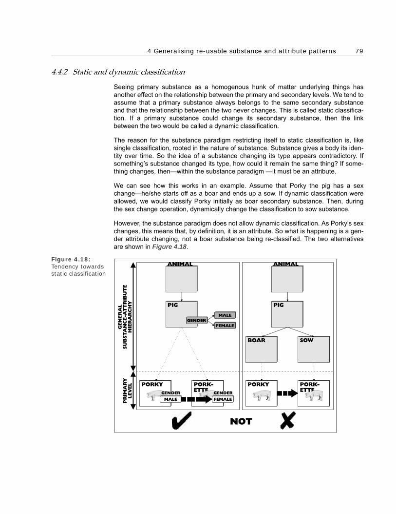
4 Generalising re-usable substance and attribute patterns 79
4.4.2 Static and dynamic classification
Seeing primary substance as a homogenous hunk of matter underlying things hasanother effect on the relationship between the primary and secondary levels. We tend toassume that a primary substance always belongs to the same secondary substanceand that the relationship between the two never changes. This is called static classifica-tion. If a primary substance could change its secondary substance, then the linkbetween the two would be called a dynamic classification.
The reason for the substance paradigm restricting itself to static classification is, likesingle classification, rooted in the nature of substance. Substance gives a body its iden-tity over time. So the idea of a substance changing its type appears contradictory. Ifsomething’s substance changed its type, how could it remain the same thing? If some-thing changes, then—within the substance paradigm —it must be an attribute.
We can see how this works in an example. Assume that Porky the pig has a sexchange—he/she starts off as a boar and ends up a sow. If dynamic classification wereallowed, we would classify Porky initially as boar secondary substance. Then, duringthe sex change operation, dynamically change the classification to sow substance.
However, the substance paradigm does not allow dynamic classification. As Porky’s sexchanges, this means that, by definition, it is an attribute. So what is happening is a gen-der attribute changing, not a boar substance being re-classified. The two alternativesare shown in Figure 4.18.
Figure 4.18: Tendency towards static classification
NOT
PIG
BOAR SOW
PR
IMA
RY
LEV
EL
GEN
ER
AL
SU
BSTA
NC
E-A
TT
RIB
UT
EH
IER
AR
CH
Y
PORKY PORKY PORK-ETTE
PORK-ETTE
FEMALE
FEMALE
MALEGENDER
PIG
ANIMAL ANIMAL
MALE
GENDERGENDER

80 Chapter 4 The Substance Paradigm’s Semantics
4.4.3 O-O programming languages
This static classification aspect of the substance paradigm has, like single classification,influenced the development of O-O programming languages. These typically follow thesubstance paradigm in having a static classification framework, where objects cannotdynamically change type. This means that, as in the substance paradigm, attributeshave to handle change.
5 Our current way of seeing
Static classification in O-O programming languages is just one of a myriad of ways inwhich the substance paradigm has influenced the way we now see things. Over thecenturies, Aristotle’s paradigm has embedded itself deeper and deeper in our con-sciousness, until it now seems a natural and normal way to see. As with most para-digms, this works at an unconscious level.
What this chapter has done is make it conscious—revealing the semantics at the heartof the substance paradigm and so also the entity paradigm. We now have a clear andconsistent idea of our current way of seeing’s semantics. We consciously appreciatewhat a substance and an attribute are; and also, what the corresponding entity andattribute signs in entity-oriented models refer to. This conscious appreciation of our cur-rent way of seeing is an essential precursor to consciously working our way forward tothe object paradigm.
5.1 The development of finer, more accurate, distinctions
The development of the substance paradigm in 4th century BC Greece was part of ageneral improvement in semantics enabled by the development of writing technologyand the invention of the alphabet. One aspect of this that is relevant to our re-engineer-ing is an overall development of finer, more accurate, distinctions. (We shall see, in laterchapters, how the re-engineering from entities to objects continues this development.)
5.1.1 Distinguishing between the literal and the metaphorical
One good example of the development of more accurate distinctions is recognising thedifference between literal and metaphorical descriptions. Before Aristotle’s time, peopledid not make this distinction. Aristotle’s teacher Plato had not quite arrived at it. In theSophist he condemns ‘likenesses’ (in other words, metaphors) as ‘a most slippery tribe’even though he is himself using one.
Aristotle, however, made the distinction both forcefully and explicitly. He condemnedmetaphors outright, insisting that they should not be used in definitions and criticisingthem in his predecessors work. For example, Aristotle criticises Empedocles fordescribing salt water as the sweat of the Earth (and so, by implication, that sweat andsea-water are the same).

5 Our current way of seeing 81
Aristotle comments:
Perhaps to say that is to speak adequately for poetic purposes—for metaphor is poetic—but it is not adequate for understanding the nature [of a thing].
With hindsight we can see that it was not so much that Empedocles was mistaken, butthat he had not developed a sufficiently accurate framework to distinguish between theliteral and metaphoric.
5.1.2 Comparing oral and literate cultures
If we compare the way oral and literate cultures see signs and sameness, we canclearly see the development of the finer and more accurate distinctions that came withwriting. The notion of a sign is quite broad. We say things like:
A rapid pulse is a sign of a fever.This footprint is a sign someone passed here recently.Pottery fragments are a sign of human civilisation.
We also talk of things as signs representing other things:
The elephant represents the (US) Republican party.The (UK) Member of Parliament represents his constituents.
We use both of these ways of talking to explain the meaning of words and symbols:
The word ‘dog’ is a sign for a dog.The symbol ‘$’ represents dollars.
At a general level, all these types of signs have something in common. But modernwestern culture, with the resources of writing, has developed a sophisticated under-standing of their differences. It recognises that the link between the word ‘dog’ and adog is not the same as the link between a rapid pulse and fever.
However, these distinctions took a long time to develop. Often oral cultures not only donot make these distinctions but also do not make a sharp distinction between the thingitself and something that represents it. A well-researched example is the Huichol Indi-ans of Mexico, who sacrifice deer to their gods. When no deer is available, they offercorn in its place. They explain this by saying that the corn is the same as deer.
This sounds amazing to our literate ears. We can see it is in their interest to say thatcorn is deer; it means they have something to sacrifice to the gods. The connections godeeper than that. For example, their mythology claims that corn was once a deer. How-ever this does not explain why, in discussions, they adamantly claim that corn and deerare the same. A claim that, to our literate minds, is unintelligible.
The Huichol are not unique: other oral cultures make similar claims. The Nuer of Sudanclaim that twins are birds. The Zafimaniry claim that the centre post of the clan’s chiefhut is an ancestor. The Puluwat Islander navigators claim that east is a big bird. Wehave similar claims in our history. Statements such as ‘this is my body’ in the Christianbible, puzzled the scholars developing a literate (and literal) understanding of text in theMiddle Ages and still puzzles some people today.

82 Chapter 4 The Substance Paradigm’s Semantics
We can understand what is going on once we realise that the problem is not with theoral cultures’ ideas of corn and deer, but with their ideas of signs and sameness. With-out the resources of writing, they have not yet developed our modern, more accurate,distinctions between different types of signs and sameness. Figure 4.19 illustrates thisdevelopment schematically. The Huichol Indians claim that corn is deer because, forthem, saying that ‘corn is deer’ is the same type of thing as saying that ‘corn representsdeer’. ‘Is the same as’ and represents’ belong to the same conceptual category.
Figure 4.19: Shift to finer, more accurate, distinc-tions
This is why the Huichol form of identity claim is common in oral cultures, but unintelligi-ble to literate ones. Oral cultures do not need as sharp a distinction as literate ones; forthem the potential ambiguity it is not a problem. We shall re-visit the Huichol Indianswhen we look at how the shift to the logical and object paradigms leads to similar devel-opments of finer distinctions. There the boot will be on the other foot. Most of us will bein the position of the Huichol Indians. We will (initially, at least) find it difficult to see whatthese new distinctions are and why they need to be made.
6 The four key types of things
We have seen that the substance paradigm, despite its extreme age, was and is sophis-ticated. We have seen how it addresses all four of the key types of things we identifiedin Chapter 2:
• How it uses the notion of primary substance and attributes to handle things’ par-ticularity.
• How it uses the notion of secondary substance and attributes to handle types. How it uses the secondary hierarchies to handle levels of generality.
• How it uses relational attributes to handle relationships—although, as we have seen, this is not really a satisfactory solution.
• How it uses shifts to new accidental attributes to handle changes—although these shifts are, in a sense, a new implicit type of particle.
For our purposes, it offers a comprehensive semantics for the four key types of things.This is why it makes such a good benchmark and starting point for our re-engineering toobject semantics.
SIMPLE 'ORAL' CATEGORY MORE ACCURATE 'LITERATE' DISTINCTIONS
'DOG' REFERS TO DOG
MEMBER OF PARLIAMENTREPRESENTS
CONSTITUENTS
CORN IS DEER
RAPID PULSE IS FEVER
SEA IS SWEAT
SEA IS SALT WATER
'DOG' REFERS TO DOG
RAPID PULSE IS FEVER
NATURALSIGNS
CORN IS DEER
MEMBER OF PARLIAMENTREPRESENTS
CONSTITUENTS
SEA IS SWEAT
METAPHORICALDESCRIPTIONS
SEA IS SALT WATER
LITERALDESCRIPTIONS
SIGNS REFERRINGSIGNS
REPRESENTING

7 What’s next 83
7 What’s next
In the last chapter, we saw why the substance paradigm was simplified into the entityparadigm and the semantic confusion this caused. We also recognised that this simplifi-cation taught us to down play, even ignore, the semantic aspects of business entitymodelling. We discussed the root cause of this, the two-dimensionality of paper and inktechnology. With the invention of computing technology, this constraint disappears andwe have an opportunity to re-introduce semantics into business modelling.
Some people may be tempted to do this within the substance paradigm’s semanticsdescribed in this chapter. It is, in many ways, an improvement on the entity paradigm. Ithas the benefits of both secondary substance and attribute hierarchies and, through theuse of independent attribute hierarchies, the potential for re-use across secondary sub-stances. But the substance paradigm is not just old; it is ancient—over two thousandyears old. There have been several generations of developments in semantics sincethen. It only makes sense to take advantage of the improvements they offer.
Furthermore, the substance paradigm seems to have a couple of potential problems inreflecting the real world accurately. We have seen how its treatment of relationships isunsatisfactory. We have also seen that its secondary hierarchies cannot handle multipleinheritance and classification. If we want to take full advantage of computing technol-ogy’s flexibility, we need to rise above these constraints.
Nevertheless, the substance paradigm plays an important part in our re-engineering ofthe information paradigm. It acts as a benchmark against which we can measure theprogress of the re-engineering. Each step forward should offer better solutions to theissues, and, in the end, more potential for re-use. In Part C, we re-engineer into the nextparadigm on our route to objects—the logical paradigm.

84 Chapter 4 The Substance Paradigm’s Semantics

BOROBORO
Part CShifting Towards Objects—The
Logical Paradigm
Chapter 5 The Emergence of the Logical Paradigm
Chapter 6 The Logical Paradigm’s Framework


BOROBORO
Chapter 5The Emergence of the Logical
Paradigm
1 Introduction
2 Origins of the logical paradigm
3 Shifting from substance to extension
4 Re-engineering primary substance
5 Re-engineering secondary substance
6 Re-engineering secondary attributes
7 Re-engineering relational attributes
8 Simplifying and generalising the information framework
9 Summary

88 Chapter 5 The Emergence of the Logical Paradigm
1 Introduction
In Part B, we clarified what the entity and substance paradigms are. Here, in Part C, were-engineer the substance paradigm into the logical paradigm. This is an important stepbecause it establishes a number of patterns that are inherited by the object paradigm. Inthis chapter we construct the logical paradigm’s framework out of its fundamental parti-cles. In the following chapter, we fill in this framework.
1.1 Re-engineering the substance paradigm
We start off this chapter, as we did with the entity paradigm, by looking at the origins ofthe logical paradigm. Then we build its framework by re-engineering the substance par-adigm. We take the substance paradigm’s four fundamental particles:
• Primary substance,
• Primary attributes,
• Secondary substance, and
• Secondary attributes.
And re-engineer them into the logical paradigm’s three fundamental particles:
• Logical classes,
• Logical tuples, and
• Individual logical objects.
2 Origins of the logical paradigm
Mathematics provided the inspiration for the logical paradigm. We shall see the mathe-matical nature of the paradigm when we look at its fundamental particles. The para-digm’s two core patterns of class and tuple (its new fundamental particles) come fromset theory. This is a branch of mathematics that has its origins in work done in the 19thcentury. Foundational work was done by a number of mathematicians; including GeorgeBoole (1815–1864), John Venn (1834–1923) and Georg Cantor (who developed mod-ern set theory between 1874 and 1897). The paradigm’s framework was developed bythe German, Gottlob Frege (1848–1925), and the American, Charles Sanders Peirce(1839–1914).
2.1 Meaning and understanding
To support his mathematical work, Frege developed a new notion of meaning that iscentral to both the logical and object paradigms. In the Prologue, we noted that theobjective of business modelling is capturing understanding. It may help us to appreciatethe importance of Frege’s work if we re-phrase this as ‘capturing meaning’.

2 Origins of the logical paradigm 89
2.1.1 Frege’s analysis of meaning as sense and reference
Frege suggests that the meaning of a concept (or sign) has two components:
• Sense, and
• Reference.
Reference is the relationship between the concept and the thing it refers to (as illus-trated earlier in Figure 2.1). Sense is the relationships a thing has to other things(reflected in a concept’s relationships to other concepts). Together these two compo-nents are a concept’s meaning.
Frege developed his analysis to resolve a problem found with earlier theories thatbased their analysis solely on reference. He used the following example to illustratehow his analysis worked and the problem it solved.
The planet Venus is visible in the morning sky, where it is called the morning star. It isalso visible in the evening sky, where it is called the evening star. If the simplistic notionof the concept’s meaning only being what it refers to is correct then, as the three con-cepts:
• The morning star,
• The evening star, and
• Venus
All refer to the same object; they should be interchangeable. However, when we inter-change them in the sentence;
Venus is Venus.
We get the sentence:
The morning star is the evening star.
Figure 5.1:Venus’s meaning map
The first sentence is obviously and tautologically true. The second sentence tells somepeople a new fact (because they do not know that both the morning star and the
EVENINGSKY
MORNINGSKY
Sg tani rn Ser no s eM
CO
NC
EP
TS
OB
JEC
TS
ng Si tn ae rvE Sen se
Reference
Senses
ni nees
ni nese
Venus
refe
rs t
o
VENUS

90 Chapter 5 The Emergence of the Logical Paradigm
evening star are Venus). In our everyday sense of meaning, the two sentences certainlyhave different meanings. This, Frege explains, is because of the different sense ele-ments in their overall meanings. We can see how different these are in the map ofVenus’s meaning in Figure 5.1.
Scholars recognise Frege’s explanation as a big step forward. The respected philoso-pher and Fregean scholar, Michael Dummett, calls it (with characteristic academic cau-tion) ‘the beginnings of a plausible account . . . of understanding’:
Frege arrived, for the first time in the history of philosophical enquiry, at whatwas at least the beginnings of a plausible account of sense, and thus of under-standing.
2.1.2 Mapping sense explicitly and accurately
Frege’s analysis enables us to neatly explain what a business model is. It is a map ofthe (Fregean) sense of the business. It is an explicit map of the objects in the businessand their patterns of relationship. This explains what reflecting the business directly—akey feature of O-O—involves.
A direct reflection faithfully and accurately maps sense—the business objects and theirpatterns of connections. An accurate map enables people to see the meaning of thebusiness clearly and directly, and so helps them to develop a better understanding of it.
An indirect reflection distorts the patterns so that they can fit into the framework of themodel, making it difficult to see the underlying objects clearly. The worked examples inPart F provide examples of this. The examples show how patterns are distorted to fitinto the entity framework of existing computer systems.
2.2 The need to determine reference
Most business modellers intuitively recognise the need to capture sense. They instinc-tively understand how sense supports reference, making a cohesive whole. They cansee that sense helps to fix reference and so they naturally model it. They see, for exam-ple, that saying ‘deal #123’ does not fix reference anything like as well as saying ‘thedeal you did yesterday with NatLand Bank for £10m’—which has more Fregean sense.
However, very few people, even business modellers, intuitively recognise the need todetermine the reference of the concepts they are using. If indeed the concepts they areusing actually refer to anything (we raised a similar point in Chapter 2—using the data–process distinction as an example). Business modellers, like most people nowadays,tend to work with concepts and ignore the objects in the world that they are meant torefer to. They treat the concepts as if they were the objects themselves. This tends tomean that the needs of the computer system (in the shape of concepts) drive the sys-tem building process, rather than the business itself (in the shape of objects).
Frege recognised that this was a serious problem. He took as a central principle (in TheFoundations of Arithmetic):

3 Shifting from substance to extension 91
. . . never to lose sight of the distinction between concept and object.
If we adopt this principle then we will never assume that we are modelling businessobjects when we are focusing on concepts.
2.2.1 The reference principle
Frege’s analysis of meaning assumes a basic principle of the logical and object para-digms—the strong reference principle. It is not difficult to grasp; indeed it seems simpleand obvious. It is that a sign (concept) in the business model explicitly refers to one andonly one object in the business. And conversely a business object is explicitly referredto by one and only one sign in the model. A simple example is given in Figure 5.2. Thisprinciple, if strictly adhered to, ensures that a business model is a direct, and so explicit,reflection of the world.
Figure 5.2: Example of the strong reference principle
One reason this principle is so central is that it implies another central principle—thateverything is an object. If every sign in the model refers to an object; then, as far themodel is concerned, everything is an object. (This includes the ‘sense’ connectionsbetween objects.) To keep things tidy and avoid confusion, it also suggests that there isno more than one sign for each object. The result is a simple, clean semantics.
For individual physical things, this principle appears obvious; for other types of things, itis more difficult to uphold. In fact, as we shall see, it has taken a substantial re-engineer-ing of the way we see things to make it work. The principle has been a major drivingforce behind many of the innovations in both the logical and object paradigm.
3 Shifting from substance to extension
A shift from substance to extension is at the core of the re-engineering to the logical par-adigm. As we shall see, both the logical and object paradigms put extension in the cen-tral place that substance occupies in the substance paradigm. Here we take a historicallook at how the substance pattern was undermined and the benefits of extension recog-nised.
BUSINESSMODEL SIGN
REFERS TO BUSINESSOBJECT
refers to
yb ot derref er si
REFERENCE PRINCIPLE
BANK

92 Chapter 5 The Emergence of the Logical Paradigm
3.1 Appreciating the difference between appearance and reality
After the development of the microscope in the 17th century, people started seriouslyquestioning the substance paradigm. Before its development, most people (and thesubstance paradigm) assumed that the world was composed of natural everyday peo-ple-sized things, such as tables and chairs. And that these things had attributes thatpeople saw and touched directly.
The microscope changed all this. People looking through it could see that everydaypeople-sized things were really composed of particles smaller than the unaided eyecould see. It soon became clear that attributes, such as taste and smell, were ideas cre-ated by the mind from the sensations of these small particles rather than inherent ineither the people-sized things or the particles.
3.2 The problem with substance
This created a climate of doubt that naturally led to questions about substance. Theghostly hulk shown in Figure 4.1, which is left behind when we take away all of a thing’sattributes, poses a problem. Not only has no one ever seen or touched such a thing; inprinciple, no one can ever examine it directly. We can only see or touch its properties.When these are gone, nothing is left for us to perceive. So we can never directly proveits existence.
In the 17th and 18th centuries, thinkers began to voice their concerns. We now look atthose raised by the Englishman John Locke (1632–1704) and the Scotsman DavidHume (1711–1776). We first see how John Locke expressed qualms about substance.Then, we see how David Hume (born seven years after Locke died) went much further,calling substance an ‘unintelligible chimera’.
3.2.1 John Locke’s qualms
John Locke most famously expressed his dissatisfaction with unknown substance inthis passage from his book An Essay Concerning Human Understanding:
§1. Ideas of substances how made.
THE Mind being, as I have declared, furnished with a great number of the simpleIdeas, conveyed in by the Senses, as they are found in exteriour things, or byReflection on its own Operations, takes notice also, that a certain number of thesesimple Ideas go constantly together; which being presumed to belong to onething, and Words being suited to common apprehensions, and made use of forquick dispatch, are called so united in one subject, by one name; which by inad-vertency we are apt afterward to talk of and consider as one simple idea, whichindeed is a complication of many Ideas together; Because, as I have said, notimagining how these simple Ideas can subsist by themselves, we accustom ourselves, to suppose some Substratum, wherein they do subsist, and from whichthey do result, which therefore we call Substance.
§2. Our Idea of Substance in general.

3 Shifting from substance to extension 93
So that if any one will examine himself concerning his Notion of pure Substancein general, he will find he has no other Idea of it at all, but only a Supposition ofhe knows not what support of such Qualities, which are capable of producingsimple Ideas in us; which Qualities are commonly called Accidents. If any oneshould be asked, what is the subject wherein Colour or Weight inheres, he wouldhave nothing to say, but the solid extended parts: And if he were demanded,what is it, that that Solidity and Extension inhere in, he would not be in muchbetter case, than the Indian before mentioned; who, saying that the World wassupported by a great Elephant, was asked, what the Elephant rested on; to whichhis answer was, a great Tortoise: But being again pressed to know what gave sup-port to the broad-back’d Tortoise, replied, something, he knew not what. Andthus here, as in all other cases, where we use Words without having clear and dis-tinct Ideas, we talk like Children; who, being questioned, what such a thing is,which they know not, readily give this satisfactory answer, That it is something;which in truth signifies no more, when so used, either by Children or Men, butthat they know not what; and that the thing they pretend to know, and talk of, iswhat they have no distinct Idea of at all, and so are perfectly ignorant of it, and inthe dark. The idea then we have, to which we give the general name substance,being nothing, but the supposed, but unknown support of those Qualities, wefind existing, which we imagine cannot subsist, sine re substante, without some-thing to support them, we call that Support Substantia; which, according to thetrue import of the Word, is in plain English, standing under, or upholding.
3.2.2 David Hume’s scepticism about substance
David Hume went much further. He wrote about ‘the fictions of ancient philosophy con-cerning substances’. His attack on substance was based, like Locke’s qualms, on ourinability to ever know anything about it.
Hume quite rightly recognised that substance played two roles. It was the home forattributes and the means for things to preserve their identity over time (we examinedboth when we looked at the substance paradigm in Chapter 4). Here is how Humedescribes the first role in his A Treatise of Human Nature:
Hence the colour, taste, figure, solidity, and other qualities combin’d in a peach . .. are conceiv’d to form one thing. . . . But the mind rests not here. Whenever itviews the object in another light, it finds that all these qualities are different, anddistinguishable, and separable from each other; which . . . obliges the imagina-tion to feign an unknown something, or original substance and matter, as a prin-ciple of union and cohesion among these qualities, and as what may give thecompound object a title to be call’d one thing, notwithstanding its diversity andcomposition.
As Hume pointed out, without substance to support it, our notion of attributes needs tochange:
The notion of accidents is an unavoidable consequence of this method of think-ing with regard to substances . . . nor can we forbear looking upon colours,sounds, tastes, figures, and other properties of bodies, as existences, which can-
94 Chapter 5 The Emergence of the Logical Paradigm
not subsist apart, but require a subject of inhesion to sustain and support them.For having never discover’d any of these sensible qualities, where, . . . we did notlikewise fancy a substance to exist; . . . [we] infer a dependence of every qualityon the unknown substance. The custom of imagining a dependence has the sameeffect as the custom of observing it wou’d have. This conceit, however, is no morereasonable than any of the foregoing. Every quality being a distinct thing fromanother, may be conceiv’d to exist apart, not only from every other quality, butfrom the unintelligible chimera of a substance.
Hume is right about the close link between substance and attributes. As we shall see,when the logical paradigm shifts from substance to extension, it has also to shift fromattributes to logical classes and tuples.
Hume also describes substance’s second role, preserving a thing’s identity over time:
When we gradually follow an object in its successive changes, the smooth pro-gress of the thought makes us ascribe an identity to the succession; . . . When wecompare its situation after a considerable change the progress of the thought isbroke; and consequently we are presented with the idea of diversity: In order toreconcile which contradiction the imagination is apt to feign somethingunknown and invisible, which it supposes to continue the same under all thesevariations; and this unintelligible something it calls a substance.
Hume explained how we preserved identity in our minds. But, he could not explain whatwas going on with the physical objects outside our minds. However, he was clear thatthe conclusions our minds jumped to were not justified by what we sensed:
Objects have a certain coherence even as they appear to our sense; but this coher-ence is much greater and more uniform, if we suppose the objects to have a con-tinu’d existence; and as the mind is once in the train of observing an uniformityamong objects, it naturally continues, till it renders the uniformity as compleat aspossible. The simple supposition of their continu’d existence suffices for this pur-pose, and gives us a notion of a much greater regularity among objects, thanwhat they have when we look no farther than our senses.
This problem of explaining how a thing’s identity is preserved over time is particularlyintractable. At the end of the following chapter, we look at the difficulties that the logicalparadigm has dealing with it. It is only when we come to the object paradigm that wearrive at a satisfactory explanation.
3.3 The benefits of extension
It was doubts about what we know that led the French thinker, René Descartes (1596–1650), to extol the benefits of extension. He was looking for ideas that could not bedoubted—and developed what has been called the ‘method of doubt’. When he appliedthis method to physical bodies, he found that the one property that he could not doubtwas extension (in other words, its length, breadth and height). There was no question inhis mind that that extension was real.

4 Re-engineering primary substance 95
Descartes still clung to the substance pattern, so he suggested that extension was theprimary essential attribute of substance. Extension is in many ways an updated versionof the Aristotelian category place—the fourth attribute category in Figure 4.19. Thisfourth category is still deeply embedded in our way of speaking, such as when we say‘someone is sitting in my place’.
Descartes also suggested that shape, size and motion were the only ‘modes’ (his namefor Aristotelian accidental attributes), and that all other attributes were mental phenom-ena:
I observed that nothing at all belonged to the nature of essence of body exceptthat it was a thing with length and breadth and depth, admitting of variousshapes and various motions. I found also that its shapes and motions were onlymodes, which no power could make to exist apart from it; and on the other handthat colours, odours, savours and the rest of such things, were merely sensationsexisting in my thought, and differing no less from bodies than pain differs fromthe shape and motion of the instrument which inflicts it.
Descartes was suggesting that extension is the one property of bodies that cannot bedoubted. It is a very attractive suggestion because extension is such a basic aspect ofour perception of the world. We see and touch extension when we see and touch indi-vidual objects, so (he argues) we cannot doubt it exists outside our mind. This givesextension a striking advantage over attributes such as taste and smell, which appear toexist in the mind. Descartes suggested a thought experiment to confirm the fundamen-tal nature of extension:
We have only to attend to our idea of some body, e.g. a stone, and remove from itwhatever we know is not entailed by the very nature of body. We first reject hard-ness; for if the stone is melted, or divided into a very fine powder, it will lose thisquality without ceasing to be a body. Again, we reject colour; we have often seenstones so transparent as to be colourless. We reject heaviness; fire is extremelylight, but none the less conceived as a body. Finally, we reject coldness and heatand all other such qualities; either they are not what we are considering in think-ing of the stone, or at least their changing does not mean that the stone isregarded as having lost the nature of a body. We may now observe that abso-lutely no element of our idea remains, except extension in length, breadth, anddepth.
In the next section, we see how the logical paradigm re-uses Descartes’ extension pat-tern.
4 Re-engineering primary substance
We start our re-engineering of the substance paradigm with its primary substance forparticular bodies.

96 Chapter 5 The Emergence of the Logical Paradigm
4.1 Bodies as extension
In the substance paradigm, the foundation of a particular body is its underlying primarysubstance (to which its primary attributes belonged). The logical paradigm uses a differ-ent foundation upon which to build its pattern for bodies. It follows through on Des-cartes’ lead and uses extension (length, breadth and height) as its foundation. (It usesextension as a replacement for substance, not—as Descartes did—an essential attrib-ute.) So when I shift from the substance to the logical paradigm, I shift from seeing mycar as a primary substance to seeing it as an extension (shown in Figure 5.3).
Figure 5.3: My car
The two patterns of particular extension and reference complement one another per-fectly here. Without extension we would not have anything tangible to refer to. It givesus a strong sense for reference. Because we can point to what we are referring to, wecan specify it accurately. Individual physical objects, such as my car, provide a goodrole model for strong reference. The task we face is making all the other types of objectsso well behaved.
4.2 What happened to primary substance’s attributes?
As Figure 5.3 suggests, we have only covered half the distance. In the Aristotelian par-adigm, particular bodies, such as my car, are composed of primary substance and pri-mary attributes. While extension can replace substance, we also have to find somethingto replace attributes. It turns out that classes fit the bill, but first we look at why primaryattributes need re-engineering.
4.2.1 The problem with primary attributes
The problem with primary attributes is that it is difficult, under a scheme of strong refer-ence, to see what we might be referring to when we talk of them. In the substance para-digm, they are mysterious things that attach themselves to even more mysterioussubstance.
Height
htdaerB
Length
ARISTOTELIAN SUBSTANCE LOGICAL EXTENSION
RED
COLOUR
PR
IMA
RY
AT
TR
IBU
TES
PRIMARY SUBSTANCE
etc.

4 Re-engineering primary substance 97
Once the logical paradigm had re-engineered substance into extension, it might haveseemed sensible to stop there and let extension take over substance’s role of havingattributes belong to it. My car would then be composed of its extension and variousproperties that belong to the extension. As Figure 5.4 illustrates, this scheme of thingshas a similar pattern to the substance paradigm.
Figure 5.4: My car’s extension with attributes
However, this would have caused problems. Under the logical paradigm’s strong refer-ence principle, all things have to have an extension—one that we can point to. So, ifextensions had primary attributes, these attributes (as things) would have to haveextension. This would have been the source of all sorts of problems.
For a start, we would not have been able to work out where we could find a primaryattribute (as extension). Consider, for example, my car’s primary attribute of redness. Itcould not exist everywhere the car does—in other words, have the same extension asthe car. If it did, it would be the same object as the car. It could not be a part of the car,such as the front half of the car, because other parts, such as the back half, are red. Itcould not exist somewhere else apart from the car. That would not make sense. Thereis just nowhere for the extension to exist.
We can push this further. Assume that we had somehow found a satisfactory extensionfor my car’s primary attribute of redness. Still, there is a problem. As the red attributehas extension, it is an object and can have properties. Assume we examine the exten-sion, taste it and weigh it. We find it tastes metallic and weighs ten pounds. The notionof a primary red attribute having a taste is odd. What is even odder is that we can, inprinciple, look and see what colour attribute it has. Let’s play safe and assume it is red.This means my car’s primary attribute of redness has a primary attribute of redness.This second level red attribute is still an attribute and so is an extension. Let’s assumewe can found the extension (remember it cannot be the same extension as the first levelattribute or else they would be the same thing). We can ask what colour the new exten-sion is and so on ad infinitum.
Making attributes extensions (something that they were not intended to be) leads to oddand contradictory results. It should be becoming clear that this is a pointless exercise
RED
COLOUR EX
TEN
SIO
N'S
PR
OP
ER
TIE
S
etc.

98 Chapter 5 The Emergence of the Logical Paradigm
because primary attributes were never designed to be extensions. Extensions, thebasis for strong reference, and primary attributes are parts of two completely differentframeworks. Primary attributes are meant to be attached to substance not extensions.Attributes need to be re-engineered into something compatible with extension.
4.2.2 The solution—transform primary attributes into classes
In the late 19th century, Georg Cantor provided the tool needed for this re-engineering.He invented the notion of a class and defined it as:
. . . the result of collecting together certain well-determined objects of our percep-tion or thinking into a single whole; these objects are called the elements of theset.
The key phrase is ‘a single whole’. This transforms a collection of objects into a singleobject.
Gottlob Frege was one of the few mathematicians to recognise the importance of Can-tor’s work when it first appeared. One of the uses to which he put it was re-engineeringthe attribute pattern into a class pattern. We can see how this works in our car example.My car’s red attribute is transformed into my car being a member of the class of redthings (shown in Figure 5.5). From the logical paradigm’s viewpoint, when I say ‘my caris red’, I mean that ‘my car belongs to the class of red things’ and not ‘my car has themysterious primary attribute of redness’.
Figure 5.5: My car belongs to the class of red things
After Frege’s transformation, there was no need for the extensionless attribute pattern.Classes, the transformed attributes, have an extension soundly rooted in the extensionsof the objects belonging to the class. They can be referred to in a strong sense. As mycar is an extension, so the class of red things is a collection of extensions (shown inFigure 5.6). This gave the logical paradigm a simpler and stronger semantic framework.
RED THINGS

4 Re-engineering primary substance 99
Figure 5.6: Referring to the class of red things
4.2.3 Referring to classes
When dealing with the extension of classes, the strong reference principle forces us tosee them more accurately than usual. In everyday life, we do not always clearly distin-guish between a collection and a fusion of extensions. When using classes to businessmodel, however, we need to. This simple example shows what happens if we do notmake the distinction. (It is taken from Willard Van Orman Quine’s book From a LogicalPoint of View.)
Figure 5.7: Our world
Assume that Figure 5.7 is our world and that its 33 regions are our individual objects.We now classify the regions into these shapes:
• An isosceles right triangle,
• A square,
• A two-to-one rectangle, and
• Two types of trapezoid.
RED THINGSC
ON
CEP
TS
OB
JEC
TS
refe
rs t
o
RED THINGS

100 Chapter 5 The Emergence of the Logical Paradigm
Figure 5.8: Shapes’ collected extensions
From a logical paradigm viewpoint, these shapes are classes of individual objects. Now,we assume (incorrectly) that the extension of a class is the fusion of the extensions ofits members. Then the extension of the class squares is the complete figure, as,between them, the five individual square shapes’ extensions cover the complete figure.The extension of the four two-to-one rectangles is also the complete figure. In fact, allthe five shape classes have the complete figure as their extension. Because objectswith the same extension are identical, we are faced with the inescapable conclusionthat all the shape classes are the same object.
This is clearly wrong. The error is assuming that the extension of a class is the fusion ofits members’ extensions. It is not their fusion but their collection (shown in Figure 5.8).This shows that what distinguishes the two-to-one rectangle and square shape classesis that they have different collections of extensions.
Once we become familiar with this more accurate way of seeing classes, we begin tosee examples of it everywhere. Quine offers us another, less theoretical, example. Heasks us to consider the states of the USA and the counties of the USA. If we see eitherthe counties or the states classes as a fusion of their individual extensions, the result isa single extension—the USA. However, if we see them as collections of their member’sextensions, we get the correct result—two separate collections of extensions.
5 Re-engineering secondary substance
The logical paradigm’s transformation does not end there. We saw earlier how the classpattern was used to re-engineer the primary attribute particle. Now, we see how it isused to transform the secondary substance particle. In the substance paradigm, general
TWO TO ONERECTANGLES
refe
rs t
o
TWO TO ONERECTANGLES
OB
JEC
TS
CO
NC
EP
TS
SQUARES
refe
rs t
o
SQUARES

6 Re-engineering secondary attributes 101
words referred to mysterious secondary substances. For example, the general word‘pig’ referred to a mysterious secondary pig substance. Because no one has ever seenor touched any secondary substance, this reference was weak. The logical paradigmoffers an alternative explanation of what general words refer to, one that uses the classpattern and so has strong reference.
From a logical paradigm viewpoint, general words, such as ‘pig’, refer to the class ofpigs. This is the collection of individual pigs. So when I say ‘Porky is a pig’, I mean that‘Porky belongs to the class of pigs’ (shown in Figure 5.9) and not ‘Porky’s primary sub-stance belongs to a (mysterious) secondary pig substance’.
Figure 5.9: Porky belongs to the class of pigs
Like the class of red things (shown in Figure 5.6), the class of pigs has an extension.This is the collection of individual pig extensions illustrated in Figure 5.10.
Figure 5.10: Referring to the class of pigs
6 Re-engineering secondary attributes
Re-engineering the secondary substance particle still does not exhaust the power of theclass pattern. It was used to transform the substance paradigm’s last fundamental parti-cle—the secondary attribute particle.
These secondary attributes could either belong to a secondary substance or live in anindependent hierarchy. For example, the secondary substances car and sock both have
PORKY
PIGS
CO
NC
EP
TS
OB
JEC
TS
PORKY
PIGS
refe
rs t
o
PIGS

102 Chapter 5 The Emergence of the Logical Paradigm
a dependent secondary colour attribute, which are both related to an independent sec-ondary colour attribute (shown in Figure 5.11).
Figure 5.11: Two types of sec-ondary colour attributes
In the substance paradigm, the two types of secondary attribute served two distinct pur-poses. The independent attributes were used to describe the hierarchy of attributes andthe dependent attributes to show their connections to substances. The logical paradigmuses the class pattern to re-engineer both types of secondary attribute, ‘killing two birdswith one stone’.
In some cases it re-uses the class re-engineered from a primary attribute. For example,the class pattern for red things in Figure 5.5 re-engineered from my car’s primary attrib-ute of redness is re-used to capture the independent secondary red attribute pattern inFigure 5.11, as shown in Figure 5.12.
Where there are corresponding dependent and independent secondary attributes,these are re-engineered into a single class. For example, the dependent and independ-ent secondary colour attributes in Figure 5.11 are re-engineered into the single class,coloured things (shown in Figure 5.12). This is not the same as the colours class, withred and green as members, which we re-engineer in the next chapter.
Figure 5.12: Re-engineering the two secondary colour attributes
We are beginning to see incontrovertible evidence that the logical paradigm’s class pat-tern works at a more general level than the substance paradigm’s patterns. It has sin-gle-handedly replaced both substance and attribute patterns, primary and secondary.
DependantSecondary Attributes
IndependantSecondary Attributes
GREENRED
COLOUR
CAR
SOCK
COLOUR
COLOUR
SUBSTANCE PARADIGM LOGICAL PARADIGM
COLOUREDTHINGS
REDTHINGS
GREENTHINGS
CAR
COLOUR
GREENRED
COLOUR
CARS

7 Re-engineering relational attributes 103
7 Re-engineering relational attributes
In Chapter 3, we looked at the substance paradigm’s semantics for relational attributesand saw that its treatment was awkward. We examined some of the problems thatattributes had in capturing the relationship pattern. This awkwardness comes out of thewoodwork in our re-engineering of relational attributes. The pattern we used earlier totransform primary attributes into classes cannot be applied to primary relational attrib-utes. They are a different kind of thing and need a different approach. We now look atthis, but first we remind ourselves of the substance paradigm’s relational attribute pat-tern and its problems.
7.1 Relational and correlational attributes
We saw in Chapter 3 how Aristotle fitted primary relational attributes into his sub-stance–attribute structure using a relational attribute pattern. He took a sentence suchas:
Queen Elizabeth is the mother of Prince Charles.
and analysed it as follows. The subject of the sentence, ‘Queen Elizabeth’ is a sub-stance. The predicate ‘is the mother of Prince Charles’ is a relational attribute belongingto the Queen Elizabeth substance. He was well aware that there was another sentencethat described the same relationship:
Prince Charles is the son of Queen Elizabeth.
Figure 5.13: Relational and cor-relational attrib-utes
He analysed this as the corresponding correlational ‘is the son of Queen Elizabeth’attribute of the Prince Charles substance. The relational and correlational attributes areillustrated in Figure 5.13 (reproduced from Figure 3.21).
7.1.1 The problem with relational attributes
We saw in Chapter 3 two semantic problems with relational (and correlational) attrib-utes. First, the connection between the relational and correlational attribute, shown by a
PR
IMA
RY
LEV
EL
PRINCECHARLES
QUEENELIZABETH
SONMOTHER
MOTHER OF SON OF
SEC
ON
DA
RY
LEV
EL
SON OF
QUEENELIZABETH
MOTHER OF
PRINCECHARLES

104 Chapter 5 The Emergence of the Logical Paradigm
line in Figure 5.13, is not explicitly captured in the substance paradigm. There relationalattributes—like all attributes—belong to only one substance.
Secondly, the substance paradigm uses two attributes to capture a single relationship. Itis perhaps easier to think of this as two signs (two relational attribute signs belonging todifferent substance signs) referring to one relationship in the world. This is clearly abreach of the strong reference principle (shown in Figure 5.2) that expects each objectto be referred to by one and only one sign. Dropping one of these attributes, as theentity paradigm does, resolves this problem but leads (as we saw in Chapter 3) to itsown semantic problems.
7.2 The solution—connection objects
The logical paradigm resolved these problems by introducing a new type of object tohelp capture the relationship pattern, the tuple.
7.2.1 Solving the reference problem
This new object, like the class object, comes from mathematics. There, a connectionbetween two things is treated as having two components, a tuple and a tuples class(where tuple is the general name for couple, triple and so on). It is easier to see howthese components work in an example. So let us re-consider the connection describedby the sentence:
Queen Elizabeth is the mother of Prince Charles.
A mathematical version of this has two components:
• A couple (a tuple of two objects), and
• A tuples class.
Figure 5.14: Referring to the <Queen Eliza-beth, Prince Charles> couple
The couple (also known as an ordered pair) is constructed from the Queen Elizabethand Prince Charles objects. It is normally written as:
refe
rs t
o
CO
NC
EP
TS
OB
JEC
TS
<QUEEN ELIZABETH, PRINCE CHARLES>
QUEENELIZABETH
PRINCECHARLES

7 Re-engineering relational attributes 105
<Queen Elizabeth, Prince Charles>.
Because this is constructed out of individual objects with extensions, the tuple, like aclass, is rooted in their extensions (shown in Figure 5.14). This means we can refer to itdirectly.
Figure 5.15: Collected together ‘is a mother of’ tuples class
We now have a new type of fundamental particle, a tuple. Because it is an object, wecan apply the class pattern to it. As Cantor explained, any object can be collected into aclass. So tuples can be collected into a class. For example, we can construct the ‘is amother of’ tuples class by collecting together the couples that would belong to it—including <Queen Elizabeth, Prince Charles>. Figure 5.15 shows the result.
So we can now translate the sentences ‘Queen Elizabeth is the mother of PrinceCharles’ and ‘Prince Charles is the son of Queen Elizabeth’ into logical-speak. Theyboth become:
<Queen Elizabeth, Prince Charles> is a member of the ‘is a mother of’ tuples class.
7.2.2 Connections between more than two objects
The substance paradigm’s relational attributes work for connections between two sub-stances. The logical paradigm’s tuples are more powerful. They can handle connectionsbetween any number of objects. Consider this sentence, which describes a three–wayconnection:
Prince William is the son of Prince Charles and the brother of Prince Harry.
This translates into the triple:
<Prince William, Prince Charles, Prince Harry>,
which is a member of the tuples class,
X is the son of Y and the brother of Z.
Tuples Class
CoupleQUEENELIZABETH
PRINCECHARLES
PRINCESSDIANA
PRINCEHARRY
PRINCESSDIANA
PRINCEWILLIAM
IS A MOTHER OF

106 Chapter 5 The Emergence of the Logical Paradigm
The following triples are also members of the same tuples class.
<Prince Harry, Prince Charles, Prince William>, and
<Prince Charles, Prince Philip, Prince Andrew>.
7.2.3 Tuple and relational attribute identity
This ability to handle multiple connections shows that the tuple pattern is fundamentallydifferent from the relational attribute pattern. We can illustrate quite neatly just how dif-ferent by comparing how identity works for relational attributes and tuples. In otherwords, comparing when two relational attributes or tuples are the same or different.Consider the connections described by the following sentences:
Prince Charles is the father of Prince William.
Prince Charles is taller than Prince William.
From a substance paradigm viewpoint, the Prince Charles substance has two relationalattributes (we ignore the correlational attributes in this example). From a logical para-digm viewpoint, there are not two attributes but a single couple belonging to two classes(shown in Figure 5.16).
Figure 5.16: Tuple identity
Where the substance paradigm uses father of and taller than relational attributes (andtheir correlational attributes) the logical paradigm uses the single <Prince Charles,Prince William> couple. The substance paradigm implies that there are two connectionsout there in the world. The logical paradigm assumes that only one connection belongsto two classes. This is quite a different way of seeing things. I have found that peopleadept at seeing in the old relational attribute way take quite a while to get proficient inthis new way.
You may have noticed that Figure 5.16 also shows an important implication of tuplesbeing objects and that they can be collected into more than one class.
PRINCECHARLES
PRINCEWILLIAM
IS A FATHER OF IS TALLER THAN
PRINCEWILLIAM
PRINCECHARLES
PRINCE WILLIAM
TALLER THAN
PRINCE WILLIAM
FATHER OF

7 Re-engineering relational attributes 107
7.2.4 Modelling many-to-many connections with tuples
In Chapter 3, we looked at the problem the substance paradigm had capturing a ‘many-to-many’ connection pattern. We also looked at two solutions within the paradigm—cre-ating ‘pseudo’ entities and creating a new relationship particle. These were illustrated inFigures 3.24 and 3.25. We saw that both of these ‘solutions’ have semantic problems;their ‘pseudo’ entities and relationship particles have difficulty referring to the worlddirectly.
The logical paradigm’s semantics for many-to-many connections has no such problems.We can see this if we re-consider the employee/project example in Chapter 3. Figure3.23 shows a number of employees working on a number of projects, including:
Employee Sue working on project #1.
Employee Sue working on project #2.
Employee John working on project #2.
From a logical paradigm viewpoint, we see this as these tuples,
<Sue, project #1>,
<Sue, project #2>, and
<John, project #2>
belonging to an ‘employee works on project’ tuples class. There is no semantic problemas the tuples (and tuples class) are objects with extensions.
7.2.5 Compacting with tuples
We can use this employee/project example to illustrate how tuples can compact infor-mation. In the example, assume that Sue manages project #1. From a substance para-digm viewpoint, we see this as a new ‘managed by Sue’ relational attribute of theproject #1 substance (ignoring the correlational attribute). From a logical paradigm view-point, there is no new object. Instead, we see the <Sue, project #1> couple, which weused in the ‘employee working on project’ tuples class, belonging to a managed bytuples class. The two views are illustrated in Figure 5.17. See how the three relationalattributes are re-engineered into a single tuple.
It is interesting to compare this with the way relational databases work. These makeexplicit use of the mathematical tuples pattern. But because they do not treat the tupleas an object that can belong to a number of classes, they cannot use a single tuple todescribe the two ‘relationships’. So they cannot compact information in the way shownin this example. In many ways, relational databases are more interested in operationallymanaging the rows and columns of stored computer information than in constructing aconsistent semantics.

108 Chapter 5 The Emergence of the Logical Paradigm
Figure 5.17: Tuples compacting information
8 Simplifying and generalising the information framework
The logical paradigm’s framework is not only more general than the substance para-digm’s, it is simpler. This is the sign of a good re-engineering. Look at Figures 5.18 and5.19. These illustrate how the logical paradigm uses less to do more. In Figure 5.18,the dependent and independent secondary colour attributes both map onto one class,coloured things. Furthermore, the primary red attribute and the independent secondaryred attribute map onto the single class, red things. In Figure 5.19, the primary relationalattribute maps onto the <my car, me> couple and the secondary relational attributemaps onto the owned by tuples class.
Figure 5.18: Comparing the paradigms—classes and mem-bers
There are also fewer, more general, types of thing—the logical paradigm only needsthree sub-types of the general type – logical objects:
• Logical classes,
• Logical tuples, and
SUEPROJECT#1
SUE/PROJECT#1
PROJECT #1
PROJECT
SUE
EMPLOYEE
SUEPROJECT
#1
MANAGES
MANAGED BY
SUE
WORKS ON
SUBSTANCE PARADIGM LOGICAL PARADIGM
CAR
COLOUR
MYCAR
RED
COLOUREDTHINGS
REDTHINGS
RED
COLOUR
COLOUR
CARS

9 Summary 109
• Individual logical objects.
Figure 5.19: Comparing the paradigms—a tuples class and its member
This can be seen clearly in the more general comparison of frameworks in Figure 5.20.This shows how, in the re-engineering, the distinction between substance and attributesdisappears completely. For instance, both secondary substance and secondary attrib-utes are transformed into classes.
Figure 5.20: Comparing the frameworks
9 Summary
In this chapter we have re-engineered the substance paradigm’s fundamental particlesinto their logical equivalents. We have just seen how this gives us a simpler and moregeneral framework. However, this is just the bare bones of the framework. In the follow-ing chapter, we put the flesh on these bare bones.
SUBSTANCE PARADIGM LOGICAL PARADIGM
ME
PERSON CAR
OWNED BY
MYCAR
OWNED BY
OWNED BYME
GENERALSUBSTANCE
PARTICULARSUBSTANCE
LOGICAL PARADIGMSUBSTANCE PARADIGM
RELATIONALATTRIBUTE
RELATIONALATTRIBUTE
NON-RELATIONALATTRIBUTE
NON-RELATIONALATTRIBUTE
NON-RELATIONAL
RELATIONAL
INDIVIDUALLOGICALOBJECTS
LOGICALTUPLES
LOGICAL CLASSES
LOGICAL OBJECTS

110 Chapter 5 The Emergence of the Logical Paradigm

BOROBORO
Chapter 6The Logical Paradigm’s Framework
1 Introduction
2 A sense framework for logical objects
3 An environment that encourages compacting
4 The problem with logical changes
5 The four key types of things
6 A new, conceptually more accurate, logical way of seeing things
7 Summary

112 Chapter 6 The Logical Paradigm’s Framework
1 Introduction
In the previous chapter we re-engineered the fundamental particles of the logical para-digm. This gave us a skeleton framework, which we flesh out in this chapter. As we dothis, we will see how the new paradigm leads to a conceptually more accurate way ofseeing.
2 A sense framework for logical objects
In the previous chapter, we focused on the extension–reference element in meaning’ssense–reference combination. We now look at the sense element—at the types ofstructures or patterns that logical objects form. This helps to fill out the meaning (and soour understanding) of the paradigm.
When logical classes and tuples are used to describe things, several useful general pat-terns regularly appear. These give the paradigm its sense framework. We look at two ofits key patterns, the super–sub-class pattern and the class–member pattern. We alsospend some time looking at an important class pattern—classes of classes—that thesubstance paradigm is not powerful enough to capture.
2.1 The super–sub-class pattern
The substance paradigm recognised a restricted form of the super–sub-class pattern inits secondary level hierarchies (which we looked at in Chapter 3). However, there wasno semantic explanation of why the hierarchies existed, or what they were. The logicalparadigm provides one and, at the same time, enhances the power of the pattern.
In the substance paradigm, secondary substances were arranged in a hierarchy of gen-erality. For instance, animal substance was regarded as more general than pig sub-stance and so had a higher position in the hierarchy. However, no real reason for thiswas given; it was taken as obvious. While it is obviously true that animal is more generalthan pig, it is not so clear why this is so within the substance paradigm. However, giventhat the notion of substance is so mysterious, this additional mystery is probably of littleconsequence.
Things are very different with classes. It is easy to explain why the class animals ismore general than the class pigs and so what the hierarchy of generality is. The classanimals is regarded as a super-class of the class pigs, which means that every memberof the class pigs is also a member of the class animals. The class animals includes theclass pigs and so it is put above it in the super–sub-class hierarchy (shown in Figure6.1). There is a perfectly straightforward physical explanation for the super–sub-classpattern; it is no semantic mystery.

2 A sense framework for logical objects 113
2.1.1 Logical class ‘inheritance’
One useful aspect of the secondary hierarchies in the substance paradigm was theinheritance pattern. In Chapter 4, we looked at how the colour attribute was inherited bythe car and van substances from vehicle substance (shown in Figure 4.15). However,within the substance paradigm, we cannot explain what this inheritance pattern actuallyis.
Figure 6.1:The super–sub-class pattern
The inheritance pattern is not lost in the shift to the logical paradigm, but it has a differ-ent basis—classes. You can see this in Figure 6.2, which shows the pattern shifting. Inthe logical paradigm, the ‘inheritance’ of the colour attribute is explained by the super–sub-class hierarchy. The classes cars and vans are coloured because they are includedin the class vehicles, which is included in the class coloured. The super–sub-class pat-tern provides a reassuringly tangible explanation for inheritance.
Figure 6.2: The shift to logical class ‘inheritance’
2.1.2 Logical class ‘multiple inheritance’
In Chapter 4, we also identified a constraint on the secondary substance hierarchydown which attributes were inherited. It had a tendency towards what O-O calls singleinheritance (see Section 4.3.1.3, "Single inheritance and OOPLs"). In the logical par-adigm, with its super–sub-class pattern, this constraint does not exist. Let’s look at thisless constrained structure.
ANIMAL
PIG
SEC
ON
DA
RY
SU
BSTA
NC
EH
IER
AR
CH
Y
SU
PER
-SU
B-C
LA
SS
HIE
RA
RC
HY
PIGS
ANIMALS
SUBSTANCEPARADIGM
LOGICALPARADIGM
...
ANIMALS
PIGS
SUBSTANCE PARADIGM LOGICAL PARADIGM
VEHICLE
CAR VAN
COLOUR
COLOUR COLOUR
VEHICLES
COLOURED

114 Chapter 6 The Logical Paradigm’s Framework
The single inheritance constraint meant a less general secondary substance could onlybelong to a single more general substance. In structural terms, it restricted the hierarchyto a tree ordering. In the logical paradigm, this constraint does not exist—a class canhave as many super-classes as is needed. This results in a lattice ordering hierarchy,which O-O calls multiple inheritance.
Figure 6.3: Logical class ‘mul-tiple inheritance’
The example in Figure 6.3 illustrates the differences between the two hierarchies. Inthe substance paradigm, single inheritance stops us from seeing the secondary boarsubstance as a combination of the more general pig and male animal substances.Whereas, in the logical paradigm, this is the natural way to see it. The class boars isclearly the result of intersecting the classes pigs and male animals. It is easy to see thisintersection’s lattice structure in the class hierarchy diagram on the right-hand side ofFigure 6.3, where the classes boars and sows both have two super-classes.
2.2 The class–member pattern
The logical paradigm has a new hierarchy pattern, one that did not (and cannot) exist inthe substance paradigm—the class–member pattern. And with it comes a new type ofclass object, a class whose members are also classes. When re-engineering entity sys-tems, I am constantly surprised at the number of implicit classes of classes they con-tain. We will come across a good example of an implicit class of classes in the re-engineering of country full names attributes in Chapter 12 (shown in Figure 12.30.)
2.2.1 A weak pattern for classes
As noted in the last chapter, when Cantor defined a class, he defined it as an object thatcould be collected into a class. However, people steeped in a pre-class way of seeingthings find this notion difficult to grasp. They often only take on board a weak pattern forclasses. For example, this has happened in most object-oriented programming lan-guages (OOPLs).
The weak pattern for classes sees a class as a collection, but does not see that a classis an object—only particular objects are objects. In this scheme of things, the idea ofcollecting together classes into a class cannot arise because weak classes are notobjects and so cannot be collected together into a class.
BOARS
PIGS
MALEANIMALS
FEMALEANIMALS
ANIMALSANIMALS
MALEANIMALS
FEMALEANIMALS
BOARS SOWSPIGS
SOWS
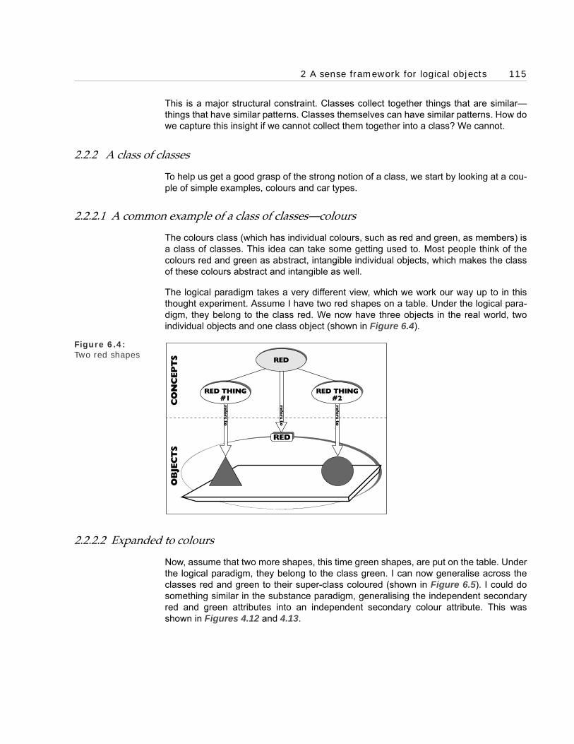
2 A sense framework for logical objects 115
This is a major structural constraint. Classes collect together things that are similar—things that have similar patterns. Classes themselves can have similar patterns. How dowe capture this insight if we cannot collect them together into a class? We cannot.
2.2.2 A class of classes
To help us get a good grasp of the strong notion of a class, we start by looking at a cou-ple of simple examples, colours and car types.
2.2.2.1 A common example of a class of classes—colours
The colours class (which has individual colours, such as red and green, as members) isa class of classes. This idea can take some getting used to. Most people think of thecolours red and green as abstract, intangible individual objects, which makes the classof these colours abstract and intangible as well.
The logical paradigm takes a very different view, which we work our way up to in thisthought experiment. Assume I have two red shapes on a table. Under the logical para-digm, they belong to the class red. We now have three objects in the real world, twoindividual objects and one class object (shown in Figure 6.4).
Figure 6.4: Two red shapes
2.2.2.2 Expanded to colours
Now, assume that two more shapes, this time green shapes, are put on the table. Underthe logical paradigm, they belong to the class green. I can now generalise across theclasses red and green to their super-class coloured (shown in Figure 6.5). I could dosomething similar in the substance paradigm, generalising the independent secondaryred and green attributes into an independent secondary colour attribute. This wasshown in Figures 4.12 and 4.13.
OB
JEC
TS
RED
refe
rs t
o
refe
rs t
o
CO
NC
EP
TS
RED THING#1
RED THING#2
refe
rs t
o
RED

116 Chapter 6 The Logical Paradigm’s Framework
Figure 6.5: The class coloured
Then, I do something new and different. Something I cannot do in the substance para-digm. I consider the red and green classes as objects and collect them together into aclass, colours (shown in Figure 6.6). I can do this because classes are objects and allobjects, even class objects, can be collected into a class. The class colours is very dif-ferent from the class coloured. Figure 6.5 shows that the class coloured has the redand green shapes as its members. Whereas Figure 6.6 that shows the class colourshas the class red and the class green as its members.
Figure 6.6: The class colours
The form of diagram used in Figure 6.6 is not wholly satisfactory. A class object (suchas red) that is also a member of another class has to be signed twice. In this case, onceas a lozenge on top of the red class oval sign containing the red member signs andagain as just a lozenge inside the colours class oval sign. We will look at a better form ofdiagramming when we examine the object notation in Part E.
CO
NC
-EP
TS
OB
JEC
TS
GREENRED
COLOURED
refe
rs t
o
COLOURED
CO
NC
-EP
TS
OB
JEC
TS
refe
rs t
o
COLOURS
GREEN
GREEN
COLOURS
RED
RED

2 A sense framework for logical objects 117
2.2.2.3 Another common example of a class of classes—user-defined car types
Classes of classes are not just of academic interest. Almost every system of a reasona-ble size has a number of them. However references to them tend to be implicit. Systemparameters and user-defined types are often classes of classes. Account types, invoicetypes, and deal types are all classes of classes.
System builders are now so familiar with these type objects that often they can—with lit-tle or no analysis—intuitively work out how to implement them. The ease and familiarityof their implementation means that the obvious, but awkward, semantic questions thatshould arise during business modelling are not asked. Questions such as:
What are these objects? and
What do they model in the business?
We now ask these question about one such user-defined type—car types. Consider asimple computer system with user-defined car types constructed using a weak patternfor classes (in other words, classes of classes are not allowed). Most current systemsare like this. To keep it simple, we only consider information about cars and car types inthe system.
We assume that the users keep records of car types on a file. On each record they set asmall car type indicator field to yes or no. We interpret this as implying that each cartype’s record refers to an individual object belonging to the car types class. If a record’ssmall car type indicator is set to yes, then we infer that the individual car type alsobelongs to the small car types class. This makes the small car types class a sub-classof the car types class.
We assume that the users also keep records of cars on a file, which can be linked to anappropriate car types record. We interpret this as saying that each car record refers toan individual object belonging to the cars class. The individual object is also linked to anobject belonging to the car types class by a tuple belonging to the types-of tuples class.
Figure 6.7: Original system
Assume that the users have already set up a record of one type of car—Minis—and setits small car type indicator ‘field’ to yes. They have also set up records of four cars—Car# 123, Car # 456, Car # 789 and Car # 890. Where Car #s 456 and 789 are Minis andso the users link their records to the individual car type record for Minis. The situation
MINIS
SY
ST
EM
-D
EFIN
ED
USER
-DEFIN
ED
CAR TYPES
SMALL CARTYPES
TYPES OFCARS

118 Chapter 6 The Logical Paradigm’s Framework
represented by the system is diagrammed in Figure 6.7. This pattern of cars and theirtypes will be familiar to most system builders.
Now, we ask the obvious question raised by the strong reference principle. What is anindividual car types object, such as Minis, in the outside world? This will tell us what thecar types and small car types classes are. To answer the question, we need the strongnotion of class, which allows classes to be members of classes.
From a logical paradigm viewpoint the answer is clear. Minis is not an individual object,but a class —the class of Minis. Cars #456 and #789 are members of it. This makes thecar types class a class of classes. The small car types class is also a class of classes. Itis the class of all the car types that are small, so Minis belongs to it. This gives us thestructure in Figure 6.8.
Figure 6.8: Car types as a class of classes
It is easier to see the class–member pattern if we show it as a hierarchy (shown in Fig-ure 6.9). Compare this hierarchy with that in Figure 6.7. Just by looking at the two, wecan see that the class–member hierarchy has a simpler more coherent structure.
Figure 6.9: Car types class–member hierarchy
#456#890
MINIS
SMALL CARS
MINIS
CARS
CAR TYPES
SY
ST
EM
-D
EFIN
ED
USER
-D
EFIN
ED
CAR #890 CAR #123 CAR #456 CAR #789
member
rebmem
re
bm
em
CARSCAR
TYPES
SMALLCARS
MINIS
SY
ST
EM
-D
EFIN
ED
USER
-D
EFIN
ED
SUB CLASS
SUB CLASS
member
mem
ber
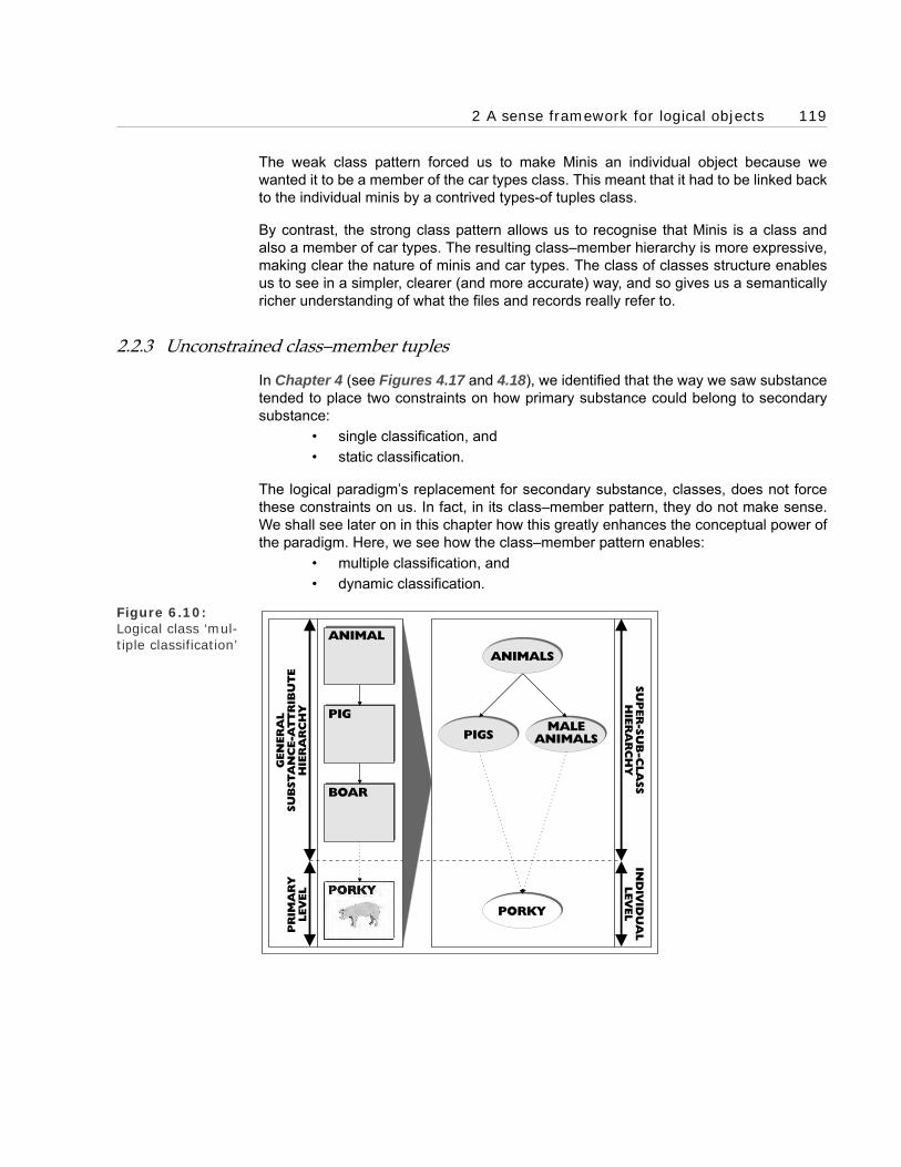
2 A sense framework for logical objects 119
The weak class pattern forced us to make Minis an individual object because wewanted it to be a member of the car types class. This meant that it had to be linked backto the individual minis by a contrived types-of tuples class.
By contrast, the strong class pattern allows us to recognise that Minis is a class andalso a member of car types. The resulting class–member hierarchy is more expressive,making clear the nature of minis and car types. The class of classes structure enablesus to see in a simpler, clearer (and more accurate) way, and so gives us a semanticallyricher understanding of what the files and records really refer to.
2.2.3 Unconstrained class–member tuples
In Chapter 4 (see Figures 4.17 and 4.18), we identified that the way we saw substancetended to place two constraints on how primary substance could belong to secondarysubstance:
• single classification, and
• static classification.
The logical paradigm’s replacement for secondary substance, classes, does not forcethese constraints on us. In fact, in its class–member pattern, they do not make sense.We shall see later on in this chapter how this greatly enhances the conceptual power ofthe paradigm. Here, we see how the class–member pattern enables:
• multiple classification, and
• dynamic classification.
Figure 6.10: Logical class ‘mul-tiple classification’
IND
IVID
UA
LLEV
EL
SU
PER
-SU
B-C
LA
SS
HIE
RA
RC
HY
PIGSMALE
ANIMALS
PORKY
ANIMALS
PR
IMA
RY
LEV
EL
GEN
ER
AL
SU
BSTA
NC
E-A
TT
RIB
UT
EH
IER
AR
CH
Y
ANIMAL
PIG
BOAR

120 Chapter 6 The Logical Paradigm’s Framework
2.2.3.1 Logical class–member ‘multiple classification’
In the substance paradigm, a primary substance could only belong to one secondarysubstance. For instance, if Porky the boar belonged to boar secondary substance, hecould not belong to any other secondary substance. In the logical paradigm, an individ-ual object can belong to as many classes as is needed. So Porky could belong to thepigs class and the male animals class (shown in Figure 6.10). This is useful, because iteliminates the need for a boar class. We examine how this enables us to compact moreinformation into less structure later on in this chapter.
As we saw in Chapter 4 (see Figure 4.16), the substance paradigm can, to an extent,escape from its single classification structure, using attributes. It does this by mimickinga limited version of multiple classification. A primary substance cannot belong to morethan one secondary substance. But, through its primary attributes, it can have morethan one link to the secondary level. Figure 6.11 has an example of this. There, bothPorky and Porkette have two links to the secondary level; one to pig secondary sub-stance, the other to a secondary gender attribute. This gives us a similar lattice struc-ture to the multiple classification in Figure 6.10.
Figure 6.11: Multiple secondary links
2.2.3.2 Logical class–member ‘dynamic classification’
Primary substance was also constrained by static classification. If a primary substancebelonged to a secondary substance, it always belonged to it; that could not change. Forinstance, if Porky the boar belonged to boar secondary substance, he always belongedto it.
The logical paradigm’s class–member pattern enables dynamic classification —a lessconstrained structure. This means an individual object can change classes if that iswhat is needed. For example, if they bring in sex-change operations for pigs and Porkychooses to become a Porkette, then we can see this as he/she dynamically transferringfrom the class boars to the class sows (diagrammed in Figure 6.12). The logical para-digm needs to explain this commonplace business pattern; one where bank accountsbecome overdrawn and deal settlements become overdue. Dynamic classification is its
PIG
PR
IMA
RY
LEV
EL
GEN
ER
AL
SU
BSTA
NC
E-A
TT
RIB
UT
EH
IER
AR
CH
Y
FEMALE
FEMALEMALE
GENDER
GENDER
ANIMAL
MALE
GENDER GENDER

2 A sense framework for logical objects 121
solution. (We will re-engineer a very different view of this pattern when we look at theobject paradigm in Chapter 8.)
Figure 6.12: Logical class ‘dynamic classifi-cation’
Again, through the use of attributes, the substance paradigm can mimic a constrainedversion of dynamic classification. A primary substance cannot change its secondarysubstance, but its primary attributes can change the secondary attributes they belongto. We can illustrate how this works with Porky’s sex change. As shown in Figure 6.13,Porky’s primary gender attribute changes its secondary gender attribute. It starts offbelonging to the secondary male gender attribute and ends up belonging to the second-ary female gender attribute. The range within which an attribute can change isrestricted. For example, a male gender attribute cannot change into a red colour attrib-ute.
Figure 6.13: Dynamic second-ary attributes
The way attributes mimic logical multiple and dynamic classification can be used totranslate an object model onto an entity-oriented database. This is a useful featurebecause it means that, with some manipulation, an O-O business model can be fullyimplemented on a traditional entity database—although this gives the database an unu-sual structure.
BEFORE AFTER
TIME
BOARS BOARSSOWS SOWS
PIGS PIGS
BEFORE AFTER
TIME
PIG PIG
PR
IMA
RY
LEV
EL
GEN
ER
AL
SU
BSTA
NC
E-A
TT
RIB
UT
EH
IER
AR
CH
Y
FEMALE FEMALE
MALE MALEGENDER GENDER
ANIMAL ANIMAL
MALEFEMALE
GENDERGENDER

122 Chapter 6 The Logical Paradigm’s Framework
I normally make use of this feature to build a validation system for the business modelon an easy-to-use PC-based entity-oriented database (such as Microsoft’s ACCESS).This means I can test the conceptual correctness of the model before it is translated intothe system specification. I find that it saves a lot of time and effort if conceptual errorsare found and fixed during business modelling. Without the validation system, theywould be embedded into the system specification and only unearthed during accept-ance testing.
2.3 The sense framework
Our look at the logical paradigm’s sense framework should have convinced us that it issuperior to the substance paradigm. There are the structural enhancements:
• The super–sub-class pattern can support a lattice hierarchy; it is no longer constrained to ‘single inheritance’.
• The class–member pattern can support multiple and dynamic classification; it is no longer constrained to single and static classification.
These benefits proceed from a superior semantics, one based on extension and strongreference. The shapes of these patterns come from a more accurate understanding ofthe connections between tangible objects in the real world. This accuracy is not boughtat the expense of complexity, quite the opposite in fact. The logical paradigm’s frame-work is simpler than the substance paradigm’s. And most of the framework that we haveexamined here, in particular the notions of class and tuple, is re-used by the object par-adigm.
3 An environment that encourages compacting
The object paradigm provides a friendly environment for generalising patterns and socompacting the model. We can see the beginnings of this here in the logical paradigm.The removal of simple structural constraints, such as single classification, has encour-aged generalisation and so increased the potential for compacting.
It is easy to dismiss the increased flexibility and sophistication of the structure of the log-ical paradigm as only marginally useful to modelling. This is only true if the new seman-tics is not understood and so the potential of the changes not exploited. When peopleunderstand the semantics (when they master the new way of seeing), they start usingits enormous potential. We now look at a simple example that illustrates one part of thisenormous potential. We see how the change from single classification to multiple classi-fication offers the potential for literally astronomic increases in conceptual economy,packing more information into a smaller space.
3.1 Example of the increased potential for conceptual economy
Consider Porky a boar, a member of the class boars, shown in Figure 6.14. What is aboar? If we look it up in a dictionary, one definition (the one we are using here) is a malepig. If we interpret this in class terms, we are saying that the class boars is the intersec-

3 An environment that encourages compacting 123
tion of the class pigs and the class male animals. In other words, as shown in Figure6.14, members of the class boars are just those members of the class pigs that are alsomembers of the class male animals.
Figure 6.14: Porky the Boar
Now that we have defined the class boars with its two super-classes, it is clearly super-fluous. We could eliminate it from the final system without losing any functionality. Theboars class would no longer exist and Porky would be directly a member of the pigs andmale animals classes (see Figure 6.15). (However, we would typically keep a record ofthe generalisation, and so the redundant boars class. This would be used to help peo-ple understand the generalised model.)
Figure 6.15: Generalised male pigs
We can see this gives us a multiple classification structure when the classes are drawnin a hierarchy, as in Figure 6.16. This type of structure is not available in the substanceparadigm, and so definitely not available to entity-oriented business modellers. It onlybecomes available with the logical paradigm.
This is a very tangible example of conceptual economy. We have eliminated a classwith no loss of information. It is also an example of generalisation using super-classes,because the two super-classes, pigs and male animals, make the lower level class,boars, superfluous, enabling us to eliminate it from the system.
PORKY
ANIMALS
MALEANIMALS
BOARS
PIGS
PORKY
ANIMALS
MALEANIMALS
PIGS
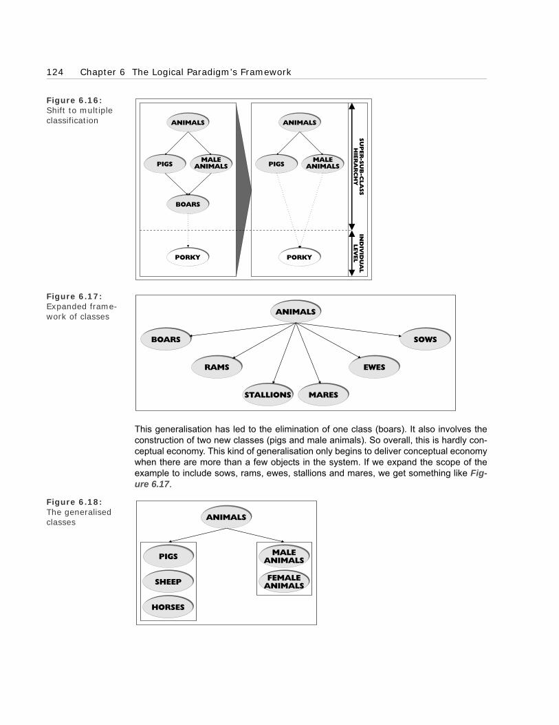
124 Chapter 6 The Logical Paradigm’s Framework
Figure 6.16: Shift to multiple classification
Figure 6.17: Expanded frame-work of classes
This generalisation has led to the elimination of one class (boars). It also involves theconstruction of two new classes (pigs and male animals). So overall, this is hardly con-ceptual economy. This kind of generalisation only begins to deliver conceptual economywhen there are more than a few objects in the system. If we expand the scope of theexample to include sows, rams, ewes, stallions and mares, we get something like Fig-ure 6.17.
Figure 6.18: The generalised classes
IND
IVID
UA
LLEV
EL
SU
PER
-SU
B-C
LA
SS
HIE
RA
RC
HY
PIGSPIGSMALE
ANIMALSMALE
ANIMALS
PORKY
ANIMALSANIMALS
PORKY
BOARS
ANIMALS
BOARS SOWS
RAMS EWES
STALLIONS MARES
ANIMALS
PIGS
SHEEP
MALEANIMALS
HORSES
FEMALEANIMALS

3 An environment that encourages compacting 125
We now generalise these classes and construct five super-classes: pigs, sheep,horses, male animals, and female animals. We can now eliminate all the six originalclasses—such as stallion (male horse) and sow (female pig)—leaving the five super-classes. Figure 6.18 shows the result. This is a similar structure to our original general-isation (shown in Figures 6.15 and 6.16), the only change is the addition of the extraclasses. This shows that the pattern in the original generalisation is fertile. It is applica-ble across a range of classes, something the lower level classes are not. We havefound a re-usable pattern.
Things are also looking up from a conceptual economy viewpoint. We started with sixclasses and ended up with five more general classes—one class less. We have made asaving, but not on a grand scale. For this to happen, we need to increase the number ofclasses we start with.
3.2 Measuring multiple classification’s potential for generalisation
If we want to measure the potential for generalisation that multiple classification offers,we take a different tack. In a generalisation, we construct a new top level of super-classes that renders all the lower levels superfluous. Their information is compressedand compacted into the more general super-classes (shown in Figure 6.19).
Figure 6.19: The stages of gen-eralisation
To measure multiple classification’s potential for generalisation, we start at the finalstage with the generalised classes and ask how many lower level classes they couldhave generalised. If we assume that the final classes are totally generalised, then work-ing out the maximum potential number of lower level classes that can be constructedfrom them is a relatively simple mathematical calculation. The results are shown inTable 6.1.
It is important to remember that the potential number of lower level classes is only ameasure of multiple classification’s theoretical power of generalisation—the actual num-ber is likely to be much less. However, the table gives us a feel for the actual power. Aswe can see, the potential increases substantially as the number of general classes getshigher. This is because the number of possible intersections gets shown in larger, so thepotential number of lower level classes that can be superseded grows exponentially.
We can use these figures to give us an indication of how multiple classification’s poten-tial for generalisation affects increases in scope and functionality. Assume that we dou-ble the number of objects in a totally generalised system. If we take the potentialnumber of lower level classes as an indication of the scope and functionality of the sys-tem classes, then this doubling of size much more than doubles the scope and function-ality. For instance, when we double a system with 10 objects, we should have atheoretical 1000 fold (1048550/1013) increase in scope and functionality. This is an
ORIGINALCLASSES
CONSTRUCTSUPER-CLASSES
ELMINATEORIGINAL CLASSES

126 Chapter 6 The Logical Paradigm’s Framework
increase of three orders of magnitude. If we had started with a larger system, theincrease would be even higher. Doubling from 100 to 200 objects gives a theoretical 30orders of magnitude increase.
These figures obviously only indicate a theoretical potential; practically, they are notgoing to be reached. But even if substantially lower levels are reached, this still repre-sents a significant increase in conceptual economy. As we discussed in the Prologue,our experience with increasing the scope of business models is of significant increasesin conceptual economy (shown in Figure P.5). We also discussed how increasing thescope of a traditional system building project does not work in the same way. This is, inpart, because it does not have access to the resources of multiple classification.
It seems difficult to understand why something that obviously makes common sense,such as generalisation, has not become a central feature of business modelling before.If getting a significant improvement in conceptual economy were easy, it would havebeen done long ago. There has to be a catch. These suspicions are well founded; thereis a catch. It is that we can find it difficult to see the general patterns for the high-levelclasses that will supersede the original lower level classes.
I have found that the secret to seeing these high-level general classes lies in the objectparadigm. This gives us a much better, much more conceptually accurate, understand-ing of what objects are, which unearths really powerful re-usable patterns. These natu-rally form the basis for very general classes. Without the paradigm, we cannot reallyexploit class’s potential for compacting through generalisation properly. In the workedexamples in Part F, we see how this works; how using the object paradigm helps us tosee the right general pattern and how this leads to compacting.
Number of general classes Potential number of lower level classes
1 0
2 1
3 4
4 11
5 26
10 101
20 10485
100 1.27 x 1030
200 1.61 x 1060
N 2N-N-1
Table 6.1: Theoretical power of generalisation

4 The problem with logical changes 127
3.3 Strong sense of object
The preceding examples illustrate how the logical paradigm provides a relatively unre-stricted environment for generalising and compacting patterns. One important reasonfor this is its strong sense of object. This means that everything in the paradigm is a log-ical object. We can see this in its two new tools for capturing patterns, classes andtuples.
Classes describe collections of objects with similar patterns. Tuples, and their tuplesclasses, describe the connections between objects that make up the patterns. Boththese tools have two important structural properties:1. They can apply to any object. In other words, there is no universal structural restric-
tion on an object belonging to a class or being a place in a couple.2. The constructed classes and tuples (and their tuples classes) are objects. This is
important because the tools cannot be applied to themselves or each other unless they are objects. In other words, class objects can be members of classes and places in tuples, and so on.
These structural properties are of practical importance. Classes and tuples, just likeindividual objects, have patterns. If the pattern capturing tools could not be applied tothem, then these patterns could not be described and the resulting model would then beless complete.
4 The problem with logical changes
We now look at how the logical paradigm deals with the last of the four key types ofthings we identified in Chapter 3—changes happening to things. While the logical para-digm provides a good semantic framework for the first three types of things, it has prob-lems with this fourth one.
4.1 Logical bodies persisting through change
As we noted in Chapter 5, substance plays two roles. It is the home for attributes andalso the means for bodies to preserve their identity over time. The logical paradigmdeals with the first role—attributes are replaced with classes of tangible extensions.However, there is still the problem of explaining bodies’ identity through change.
The problem, which the English thinker David Hume so precisely describes (but doesn’tresolve) in his A Treatise of Human Nature, still exists for the logical paradigm. He setsout the objective:
Our chief business, then, must be to prove, that all objects, to which we ascribeidentity, without observing their invariableness and uninteruptedness, are suchas consist of a succession of related objects.
And then uses a series of thought experiments to show that it is impossible to achieve:

128 Chapter 6 The Logical Paradigm’s Framework
. . . suppose any mass of matter, of which the parts are contiguous and connected,to be plac’d before us; ‘tis plain we must attribute a perfect identity to this mass,provided all the parts continue uninterruptedly and invariably the same, what-ever motion or change of place we may observe either in the whole or in any ofthe parts. But suppose some very small or inconsiderable part to be added to themass or subtracted from it; tho’ this absolutely destroys the identity of the whole,strictly speaking; yet as we seldom think so accurately, we scruple not to pro-nounce a mass of matter the same, where we find so trivial an alteration. . . .
There is a very remarkable circumstance, that attends this experiment; which isthat tho’ the change of any considerable part in a mass of matter destroys theidentity of the whole, yet we must measure the greatness of the part, not abso-lutely but by its proportion to the whole. The addition or diminution of a moun-tain wou’d not be sufficient to produce a diversity in a planet; tho’ the change ofa few inches wou’d be able to destroy the identity of some bodies. . . .
This may be confirm’d by another phenomenon. A change in any considerablepart of a body destroys its identity; but ‘tis remarkable, that where the change isproduc’d gradually and insensibly we are less apt to ascribe to it the same effect.. . .
But whatever precaution we may use in introducing the changes gradually, andmaking them proportionable to the whole, ‘tis certain, that where the changes areat last observ’d to become considerable, we make a scruple of ascribing identityto such different objects. There is, however, another artifice, by which we mayinduce the imagination to advance a step farther; and that is . . . some commonend or purpose. A, ship of which a considerable part has been chang’d by fre-quent reparations, is still considered as the same; nor does the difference of mate-rials hinder us from ascribing an identity to it. . . .
But this is still more remarkable, when we add a sympathy of parts to their com-mon end, . . . This is the case with all animals and vegetables; . . . The effect of sostrong a relation is . . . that in a very few years both vegetables and animalsendure a total change, yet we still attribute identity to them, while their form,size and substance are entirely altered. An oak, that grows from a small plant to alarge tree, is still the same oak; tho’ there be not one particle of matter . . . thesame. An infant becomes a man, and is sometimes fat, sometimes lean, withoutany change in his identity.
These puzzles over what makes something the same have a long history. In Chapter 4,we looked at how the substance paradigm explained sameness over time with the mys-terious notion of substance (see Figure 4.6). In the last chapter, we saw how the logicalparadigm has replaced mysterious substance with the more physical notion of exten-sion. However it cannot solve the problems of identity persisting through time. Ournotions of sameness and identity need to evolve into something more sophisticatedbefore we can see a solution. We have to wait for the next stage of evolution, the objectparadigm, for this to happen.

4 The problem with logical changes 129
4.1.1 The whole–part pattern persisting through time
This problem with identity spills over to the whole–part pattern (the study of which isknown as mereology). This was and is an important pattern. It was analysed by Aristotleand plays an important part in current O-O analysis and design, along with the class–member pattern. Interestingly, in Frege’s time what we call classes and wholes wereboth called classes: one a collective class, the other a distributive class. And both typesof classes were studied by mathematicians—mereologic was a part of logic. Nowadaysmathematicians tend to only be interested in the class–member pattern.
The logical paradigm’s notion of extension may seem, at first sight, to offer a semanticexplanation of wholes and parts. After all, is a part not something whose extension iscontained in the extension of the whole? This works for a point in time, but—like identity,and for the same reason—does not work over time. My hand, now, is part of my arm,now. But is my hand, now, a part of my arm tomorrow? Is being a part tied into amoment of time?
For hands and arms this is not much of a problem, but the issue goes deeper when wemove from parts in space into parts over time. We talk about the morning being part ofthe day, of our childhood being part of our life. These whole–part patterns do not fit intothe logical paradigm’s extension-based explanation. We need to wait for the object par-adigm’s more sophisticated notions of extension and sameness to resolve these difficultpuzzles.
4.2 Logical changes
The notions of bodies and changes are intimately connected. The problem of identity asbodies persist through time has another side. This is working out what the changes thathappen to the body are. In the substance paradigm, they were not a thing, but whathappened to accidental attributes. The logical paradigm’s replacement for changingattributes is dynamic classification. This is the same as we discussed earlier where anobject shifts from one class to another (shown in Figure 6.12).
Figure 6.20: Dynamically clas-sifying extensions
TIME
BEFORE AFTER
REDTHINGS
GREENTHINGS
REDTHINGS
GREENTHINGS

130 Chapter 6 The Logical Paradigm’s Framework
It would have been ideal if the logical paradigm could have found a way to makedynamic classifications objects. Then, they could have participated in object’s usefulpatterns; for instance, we could have had classes and tuples of dynamic classificationobjects. The problem is that if dynamic classifications are objects, they have to haveextensions, and it is unclear what the extension could be. This thought experiment illus-trates the problem.
Assume that there is a tomato on the table. It is currently green, so a member of theclass, green things. Assume it instantaneously turns red, so becoming a member of theclass, red things. In logical-speak, it is dynamically re-classified. What is happeningfrom an extension viewpoint? As extensions exist at instants, we could say that at everyinstant up to a certain point, the instantaneous extension belonged to the class greenthings. And then at every instant after that point, the instantaneous extension belongedto the class red things. This is an acceptable explanation, but, like the substance para-digm, it puts the dynamic classification on a different dimension. Dynamic classificationhappens to objects, it is not an object (illustrated in Figure 6.20).
If we were keen to make the change an object, to say it is the instantaneous extensionof the tomato when it changes colour would be a strong temptation. We can use the log-ical paradigm’s version of Zeno of Elea’s paradox to show this leads to contradictions.We looked at the substance paradigm’s version in the discussions of Aristotle’s notionof change in Chapter 4. There, we used the paradox to show that motion—a type ofchange—could not be an attribute. Here, we use it to show that dynamic classificationscannot be extensions and so cannot be objects.
If the tomato’s change is an instantaneous extension, then as the tomato is coloured, itmust have a colour at that instant. This cannot be red or green, otherwise it would notbe changing. So it must be some other colour. Even if we assume it has a colour, theproblem re-surfaces. Let’s assume it is blue; in other words, its instantaneous extensionbelongs to the class blue. We are back where we started, only with two dynamic classi-fications—one from red to blue and another from blue to green. However many instantswe select, the same problem occurs. Dynamic classifications cannot be consistentlytranslated into extensions and so objects.
There are no practical, operational problems with using dynamic classifications in busi-ness modelling. What is at issue is a missed opportunity. From a semantic viewpoint,dynamic classifications are inadequate and this compromises the conceptual power ofthe business model. We can see the semantic inadequacy of dynamic classificationsfrom the way they breach the strong reference principle. They are not objects, they donot have an extension, so we cannot refer to them directly. The connection between theconcept and object is mysterious, because the object is mysterious.
5 The four key types of things
We can see how far the logical paradigm has taken us from the substance paradigm bylooking at the four key types of things we identified in Chapter 3:
• particular things,
• general types of things,
6 A new, conceptually more accurate, logical way of seeing things 131
• relationships between things, and
• changes happening to things.
In the substance paradigm, a thing was particular if it had primary substance and gen-eral if it had secondary substance. My car is particular because it has primary sub-stance and car is general because it has secondary substance. In the logical paradigm,a thing is particular because it is an individual extension and general if it is a class ofextensions. My car is particular because it is an individual extension and the cars classis general because it is a collection of extensions. The notion of primary substance hasbeen replaced by the notion of extension, and the notion of generality by that of class.
In the substance paradigm particularity and generality applied to attributes as well assubstance. From the logical paradigm perspective, the attributes divide into two types,non-relational and relational. Non-relational attributes, both particular and general,become classes. For example, my car’s particular redness and redness in generalbecome the class of red things.
Relational attributes take us onto the third key type of thing—relationships betweenthings. The substance paradigm’s relational attributes are re-engineered into somethingquite different—a tuple and a class. My car’s ownership relational attribute becomes thecouple <my car, me> and the owned by tuples class.
For the first three types of things, the logical paradigm has made a substantial changeto (and a substantial improvement upon) the substance paradigm. However in the fourthtype of thing—changes happening to things—it does not contribute much. In fact, as theSection 4, "The problem with logical changes"’ shows, the shift from substance toextension means that the advantage an unchanging substance has in explaining howobjects persist through time has been lost.
Furthermore, neither the substance nor the logical paradigm offers an explicit descrip-tion of what changes are. This problem with changes, along with the problem of what itmeans for bodies as extension to persist through change, is resolved by the object par-adigm’s semantics, which we look at in Part D.
6 A new, conceptually more accurate, logical way of seeing things
Working within the logical paradigm’s new semantics involves a new, conceptually moreaccurate, way of seeing things. In Chapter 4 we discussed how the development ofpaper and ink technology led to a more accurate notion of signs. There is a similardevelopment here.
6.1 A new, conceptually more accurate, whole–part pattern
For instance, the logical paradigm has developed a more accurate distinction between awhole–part and a class–member tuple than we are used to. Currently most of us would

132 Chapter 6 The Logical Paradigm’s Framework
regard the expressions ‘part of a group’ and ‘a member of a group’ as interchangeable.In our ordinary everyday language there is no real distinction between:
John is part of the technical services group, and
John is a member of the technical services group.
However within the more accurate logical paradigm there is a distinction—being a partand being a member are quite different. So which of the two is the person’s connectionwith the group? We can work this out logically because:
If A is a part of B, and
B is a part of C, then
A is also a part of C
Consider a person’s hand, it is undoubtedly part of the person. Therefore, if the personis part of the group, his or her hand would also be part of the group. In logical format:
If a person’s hand is a part of a person B, and
A person is a part of a group, then
The person’s hand is also a part of the group.
However, the person’s hand is clearly not part of the group, so the person’s connectionto the group cannot be whole–part. But it can be class–member, as this logical formatshows:
If a person’s hand is a part of a person, and
A person is a member of a group, then
The person’s hand is not normally a member of the group.
This implies that the group is a class and not a whole.
We saw (in Chapter 4) why the Huichol Indians thought corn was the same as deer.They did not need as accurate an idea of signs and sameness as us (the shift to moreaccurate distinctions was illustrated in Figure 4.19). Similarly, some people quite hap-pily talk and think of people as part of groups in the ‘same’ way as they think of their fin-ger as part of their hand. They have not yet acquired the logical paradigm’s moreaccurate way of seeing whole–part patterns. This shift is illustrated in Figure 6.21.
Figure 6.21: Shifting to more accurate logical distinctions
6.2 Other new, conceptually more accurate, patterns
The logical paradigm also leads to other new distinctions. In ordinary everyday lan-guage it is easy to confuse a sub-class tuple with a class–member tuple. For example,
SIMPLE PRE-LOGICAL CATEGORY MORE ACCURATE LOGICAL DISTINCTIONS
MY FINGERIS PART OFMY HAND
PERSONIS A MEMBER OF
THE GROUP
MY FINGERIS PART OFMY HAND
PERSONIS A MEMBER OF
THE GROUP
WHOLE-MEMBER WHOLE-PART CLASS-MEMBER

7 Summary 133
we do not normally say ‘Rover is a member of the class dogs’ and ‘dogs is a sub-classof mammals’. Instead we say ‘Rover is a dog’ and ‘a dog is a mammal’ using the sameconnecting ‘is a’ phrase. This makes the two easy to confuse. Since the logical para-digm explained what the two are, logicians have been clear on the difference. Howeverbefore the logical paradigm, even logicians had problems. For example, even the 17thcentury thinker Gottfried Leibnitz, who has been called one of the all time great logi-cians, was confused about the difference at times.
The logical paradigm is much newer than the earlier paradigms; it is barely a hundredyears old. This is an issue, because it can take centuries for a new way of seeing to beabsorbed into a culture and become a standard part of the way people see things. Itmeans that the logical paradigm has not really had time to sink in. This is particularlytrue with its notions of a class of classes and a tuples class. However, the slow overallprogress of assimilation of class patterns is perhaps surprising given that most school-children are taught them in mathematics lessons.
Most people find classes of classes an unnatural idea. The colours and car types exam-ples in this chapter may seem logically correct but do not feel natural. When peoplestart business object modelling they tend to find it difficult to spot a class of classes,even when it is staring them in the face.
The notion of a relational attribute is more insidious. We probably feel more comfortablewith the idea of a connection as a separate tuple object, rather than an embedded rela-tional attribute. For example, we are happy to see my ownership of my car as a sepa-rate object from both me or my car. However we tend to see each of these connectedobjects as having its own identity. We can demonstrate this with the example illustratedin Figure 5.16. Most people naturally assume that the sentences ‘Prince Charles is thefather of Prince William’ and the ‘Prince Charles is taller than Prince William’ refer to dif-ferent connections. They do not naturally assume that both sentences refer to the sameconnection (a couple) that is a member of two tuples classes: father of and taller than.To them, the logical paradigm’s more accurate way of seeing is counterintuitive.
All these new ways of seeing are inherited by the object paradigm. If we want to busi-ness object model, then we need to master them—this involves not just understandingthe principles but actually seeing in the new way. This takes practice. The workedexamples in Part F are a good starting point, but for most people it will take some timebefore the new way of seeing is embedded so firmly that it becomes instinctive.
7 Summary
The logical paradigm provides us with a semantic replacement for the substance para-digm (or at least a replacement for the first three of the four key types of things).Because it is based on tangible extension, it is immune to the criticisms of mysteriousunknowable substance.
The backbone of the paradigm is the strong reference principle that asserts that con-cepts can only refer to objects with extension. This was a guiding light in the re-engi-neering of the substance paradigm, which transformed the substance paradigm’s

134 Chapter 6 The Logical Paradigm’s Framework
particles into the simpler and more general particles of the logical paradigm, the classand the tuple.
The re-engineering not only simplified the particles, it made them more general and somore powerful. The new particles can handle multiple ‘inheritance’, multiple classifica-tion and dynamic classification. This enables a new logical environment that is muchmore generalisation-friendly than the substance or entity paradigms.
This shift to the logical paradigm takes us halfway along the evolution to object seman-tics. It has prepared the ground for the shift to the object paradigm, which we now makein Part D.

BOROBORO
Part DShifting to the Object Paradigm
Chapter 7 Physical Bodies as Four-Dimensional Objects
Chapter 8 Shifting to the Object Paradigm


BOROBORO
Chapter 7Physical Bodies as Four-Dimensional
Objects
1 Introduction
2 The logical semantics for physical bodies
3 The shift to object semantics
4 Physical stuff objects
5 Classes of four-dimensional objects
6 Tuples of four-dimensional objects
7 A new way of seeing bodies—a key type of thing
8 Summary

138 Chapter 7 Physical Bodies as Four-Dimensional Objects
1 Introduction
To people familiar with object-oriented programming, it might appear that logical seman-tics has all that object-orientation needs. At an operational level they are right, but at anunderstanding level—the level of business modelling—they are missing something. Aswe saw in the final sections of the previous chapter, the logical paradigm’s semanticsare shaky for the last of the four key types of things—changes. The shift to the objectparadigm is driven by the need to give change a firm semantics.
So in Part D, we focus on the object paradigm’s semantics for change. We do this in twoparts. In this chapter, we deal with the semantics of physical bodies, persisting throughchanges. In the following chapter, we consider the semantics of the changes them-selves.
We start this chapter with a series of thought experiments that clarify the logical seman-tics for physical bodies, persisting through changes and the issues it raises. We thenexplore the shift to object semantics for physical bodies and see how it resolves theissues raised by logical semantics.
Then, we look at an example of how the new object semantics for physical bodies cantransform our current notions. We see how our notion of ‘stuff’ is re-engineered into thesemantically richer notion of stuffs as physical bodies.
Finally, we re-engineer the logical notions of class and tuple objects constructed fromphysical bodies.
2 The logical semantics for physical bodies
The evolution from logical semantics to object semantics involves a pure shift in ourunderstanding of what objects, whether bodies or changes, are. In Chapter 1, we usedan ambiguous picture as an analogy for how paradigm shifts work. This is useful forexplaining what happens in the shift to object semantics. In Figure 7.1 (based uponFigure 1.2), when we shift from seeing two faces to seeing a vase, nothing in the under-lying picture changes. In the same way, the shift to object semantics does not involveany new facts, just a new way of seeing the old facts.
Figure 7.1:Shifting views
FACE
BROW
NOSELIPS
CHIN
VASESTEM
LIP
BASE

2 The logical semantics for physical bodies 139
This new way of seeing resolves a central problem for physical bodies, explaining howidentity persists through change. We have illustrated this problem before with a lepidop-ter. Over time it goes through various stages. We need to be able to explain why andhow these different stages are, in some sense, the same object; even though, forinstance, the butterfly stage of the lepidopter is so obviously different from its caterpillarstage. We saw in Chapter 4 how Aristotle’s substance paradigm gave a consistentexplanation (illustrated in Figures 4.5 and 4.6), but one based on the now discreditednotion of substance. In Chapter 6, we saw that logical semantics cannot give an expla-nation; that something can both be the same and different at different times is a myste-rious fact.
Before we make the shift away from logical semantics, we give ourselves a context byexamining our current intuitions about physical bodies’ identity over time. We do this inthree thought experiments:
• The wrecked car,
• The car-minus, and
• The chairman experiments.
These reveal how we determine whether physical bodies are the same at different timesand how ‘two’ physical bodies can be the same at one time and different at anothertime. We gain further insight by examining how the substance paradigm deals withthese thought experiments.
2.1 Wrecked car thought experiment
We instinctively use a key criterion to decide whether an object is the same at differenttimes—this is whether it has persisted continuously through time. In everyday life, weoften make the decision on the basis of how the physical body looks and feels. This firstthought experiment is designed to show how seriously we take the criterion of continuityand that the look and feel of a physical body are only practical stand-ins.
Assume I buy a brand new car. Using an advanced science fiction device, supplied tome for this experiment, I make a record of the type and position of every atom in the car.I then lend my car to a friend for a week.
At the end of the week, he brings me two cars. They are the same make and model, butone is brand new and the other is a smashed up wreck. He says that one of the cars ismine and asks me which one. The smashed up car does not look at all like my originalnew car; everything is either bent, torn or scraped. But the other car does. I doublecheck by using the science fiction device to get a picture of its atomic structure, which Icompare with the record I made at the beginning of the week. They match perfectly.With this evidence, it would only be natural for me to assume this is the car I bought atthe beginning of the week.
Now my friend introduces me to a camera crew who have been filming my car over thelast week. They show me their film. It starts at the beginning of the week and follows,without a break, everything that happens to the car and ends up with my friend bringingthe two cars in to me. In the film, I see my car going through a number of accidents untilit is the smashed up wreck that is before me now. Now I realise that the smashed up car

140 Chapter 7 Physical Bodies as Four-Dimensional Objects
is, in fact, mine. Now I am not, and you wouldn’t be, tempted to say that the new car ismine.
Why is this? It is because there is a continuous link between the car at the two times.This takes precedence over any evidence about how the car looks and feels. Continuityis the key criterion. It is the ultimate basis for our judgements on whether things are thesame at different times. But it does not explain why they are the same.
2.2 Car-minus thought experiment
At any one time, two objects must either be the same or different. In this thought exper-iment, we see that the same is not true over time. Sameness can change over time; twoobjects can be different at one time and then the same at a later time.
Assume, again, that I bought a new car last week. An object is an extension, so I canconstruct an object by specifying an extension. Assume that I did this when I bought mycar; assume I chose an extension, consisting of the car minus its back seats—andcalled it car-minus. Car-minus is obviously different from my car; they have differentextensions. Car and car-minus are also both physical bodies that persist through time.
Now, assume that today I take the back seats out of my car and destroy them. Then, mycar has changed; it is now without any back seats. But car-minus has not changed; theback seats were never part of it. It would appear that car and car-minus now haveexactly the same extension; my car minus its back seats.
Under logical semantics, this means they must be the same object. Because physicalbodies are instantaneous extensions, at a particular time, one can determine whetherthey are the same or different by seeing whether they occupy the same extension. Wecannot meaningfully ask this question in the same way about physical bodies at differ-ent times. Because they change position, shape and size, their extension is not a relia-ble guide.
2.3 Chairman thought experiment
The car-minus experiment is contrived. It was meant to be, so that we could see the sit-uation clearly. Because it is academic, I’m sure some (probably most) of you aretempted to dismiss it as irrelevant to anything commercial. But you should not. Anyphysical body could end up in a similar situation. We can see this in the followingthought experiment that uses a modern version of an ancient puzzle; one that wasknown well before Aristotle’s time. The puzzle was often expressed as a question—cantwo things be in the same place at once?
Consider Mr. Jones, the Chairman of NatLand Bank. Under logical semantics, if theconcept ‘Chairman of NatLand Bank’ is legitimate it must refer to an object, similarly forthe concept ‘Mr. Jones’. In fact, we know they are both concepts and refer to the sameobject.
Technically speaking, under logical semantics, objects are extension. And if whatappears to be two objects share the same extension (in other words, have the same

2 The logical semantics for physical bodies 141
height, width and depth), they are really the same object. Two objects cannot have thesame extension at the same time. Because we know that the concepts ‘Chairman ofNatLand Bank’ and ‘Mr. Jones’ refer to the same extension, they must, by the logicalsemantics’ definition, refer to the same object.
We now move on a week or two. Mr. Jones has resigned his chairmanship and Mr.Smith has been appointed the new chairman. From logical semantics’ perspective, theconcept ‘Chairman of NatLand Bank’ now points to the same extension as the concept‘Mr. Smith’ (shown in Figure 7.2). It is plain that the concept ‘Chairman of NatLandBank’ has changed its reference and now points to Mr. Smith. And this is not a specialsituation with an obscure case; it occurs in every business with every position, from teaboy up to managing director.
Figure 7.2: Changing refer-ence
Figure 7.3: A lepidopter sub-stance—caterpil-lar and butterfly attributes
2.4 Aristotle’s explanation of the experiments
These questions about how sameness over time works are ancient. In Chapter 4, wesaw how Aristotle developed his notion of substance in a way that, as far as he was
MO
DEL
DO
MA
IN
Mr Smith Mr SmithMr Jones Mr Jones
TIME
refe
rs t
o
refe
rs t
o
Chairman ofNatland Bank
Chairman ofNatland Bank
BEFORE AFTER
TIME
LEPIDOPTER#1
LEPIDOPTER#1
CATERPILLAR BUTTERFLY

142 Chapter 7 Physical Bodies as Four-Dimensional Objects
concerned, gave a clear explanation. We illustrated this with the example of the stagesin a lepidopter’s life. In the substance paradigm, the caterpillar and butterfly stages ofthe lepidopter were the same because they had the same substance. The reason theylooked and felt so different is that they had different attributes (shown in Figure 7.3). ForAristotle, one of substance’s main purposes was to explain sameness over time. Whenlogical semantics replaced the notion of primary substance, it could no longer use Aris-totle’s explanation.
Faced with the three thought experiments, Aristotle could use substance to give clearanswers. In the wrecked car experiment, he would say that the two cars were the samebecause, like the lepidopter, they had the same substance.
In the car-minus thought experiment, Aristotle would say that my car and car-minus (ifhe accepted that car-minus existed) are different substances. He would explain whathappened when I took the back seats out of my car as two substances starting to sharethe same place (shown in Figure 7.4) where place is the Aristotelian equivalent ofextension.
Figure 7.4: My car and car-minus sharing a place attribute
Aristotle would have offered a similar explanation to the Chairman of NatLand Bankthought experiment. He would have suggested that there is a third substance, theChairman of NatLand Bank, in addition to the Mr. Jones and Mr. Smith substances. Thisshares a place attribute with the other two substances at different times (shown in Fig-ure 7.5).
Figure 7.5: Chairmen sharing place predicates
BEFORE AFTER
TIME
CAR-MINUSMY CAR CAR-MINUSMY CAR
PLACE
#1 #2 #2
PLACE PLACE
CHAIRMANMR JONES MR JONES
MR SMITH
BEFORE AFTER
TIME
CHAIRMANMR SMITH
PLACE
#2 - ACME BOARDROOM
PLACEPLACE
PLACE
#1 - JONES HOME
#2 - ACME BOARDROOM#1 - SMITH HOME

3 The shift to object semantics 143
3 The shift to object semantics
Aristotle’s explanations of the three thought experiments show the benefits, when cap-turing change patterns, of having place (his version of extension) as an attribute cate-gory rather than a foundation for physical bodies. However, we should not be temptedto retreat back to substance. Object semantics’ shift to a new particle for physical bod-ies provides us with a much better tool for capturing these change patterns.
3.1 The origins of object semantics
We start the re-engineering by looking at its origins in a new way of seeing developed inphysics. The role model for this way of seeing was Albert Einstein’s amalgamation ofspace and time to space-time in his theory of relativity. This is not normally applied ineveryday life, to ordinary people-sized objects. However, a number of people (includingone of today’s leading philosophers, Willard Van Orman Quine) saw how Einstein’snotion of space-time can be used to resolve the problems of identity of people-sizedphysical bodies. As Quine says:
Our ordinary language shows a tiresome bias in its treatment of time.
This ‘tiresome bias’ is treating time as something completely separate from space. Hisanswer is to follow Einstein and treat time as another dimension on a par with space’sthree. One of the benefits of this shift was that the patterns for space and time wereamalgamated into general patterns for space-time. As we shall see, this proved particu-larly fruitful for whole–part patterns. The key shift we focus on here is in the centralnotion of extension; from space-based and three-dimensional to space-time based andfour-dimensional.
3.2 Explaining our intuitions
This shift takes some getting used to. However, once we do, it seems natural; it appearsto be an explicit explanation of what we have already grasped intuitively. It certainly fitsin neatly with many of our intuitions. For instance, it not only respects our intuition thatcontinuity is a key factor in identity, but explains why by giving continuity a physicalembodiment.
3.2.1 A four-dimensional lepidopter
We can see how this works with an example. In logical semantics, individual physicalbodies are extensions and extension is three-dimensional; height, width and depth. Alepidopter in a caterpillar state is a physical body with a three-dimensional extension.Similarly when a caterpillar metamorphoses into a butterfly, it is also an object and so isalso a three-dimensional extension, but a different one. What makes these two exten-sions the same object is that there is a continuous link of time-stages between the cat-erpillar and the butterfly.

144 Chapter 7 Physical Bodies as Four-Dimensional Objects
The new object semantics follows Quine and Einstein’s lead and assumes extension isfour dimensional: space’s three dimensions and the time dimension. In it, the lepidopteris one four-dimensional object. The two, three-dimensional objects from logical seman-tics are now just slices in time of the new four-dimensional object as illustrated in Figure7.6.
Figure 7.6: A four-dimensional lepidopter
In this four-dimensional way of looking at things, continuity across time is now the sameas continuity across space. We can look up and down a lepidopter in space or backwardand forward in time along it. The continuity in time that we merely intuitively graspedbefore is now transformed into something as physical and tangible as continuity acrossspace.
3.2.2 The general trend away from egocentricity
We can see this shift to space-time is part of a general trend—a trend from an egocen-tric to a more ‘objective’ view of the universe. When children are young, they see theworld revolving around themselves. As they grow up, they begin to realise it does not. Insome ways, adults still retain an element of that egocentric attitude. For instance, mostof us half believe in a variation of Murphy’s law—that things happen when they are mostinconvenient for us. So, we half suspect that it is raining because we forgot our umbrellaor because we were going out to play tennis. Whereas, ‘objectively’ we know that theweather is not influenced by our future plans.
We can see a similar egocentric attitude in the earth-centred theory of early astronomy.This assumed that because people see the earth standing still and things moving in theskies, the earth must be standing still and the planets and stars moving. When, in the15th century, Copernicus suggested the earth was just another planet moving aroundthe sun, he was suggesting a less egocentric view of the cosmos. One in which humanslost their special position at the centre of the universe.
Copernicus’ theory overturned an egocentric view of space. Quine and Albert Einstein’stheories take this one step further and overthrow an egocentric view of time. Weassume that, because we are at a particular point in time, our position must be special.This is egocentric. Why should the point in time that we inhabit (called the present) havea special quality? Most people do not think, when walking down a path, that that pointon the path is special because they are there. The present is much like any other pointin time. In fact, all points in time have been, or will be, at some time the present.
CaterpillarTime Slice
ButterflyTime Slice
FOUR-DIMENSIONALLEPIDOPTER
OBJECT

3 The shift to object semantics 145
We tend to think of space and time as different because our experiences of them are sodifferent. But we are interested in the things in themselves, not how we experiencethem. Just because something looks different, does not mean it is different. This is par-ticularly clear when we can use two senses to ‘perceive’ the same type of object. Whenwe touch one banana and taste another we get very different feelings; but we have noproblems in recognising them as belonging to the same type of thing. We should thinkabout perceiving time and space in the same way; that we are perceiving the same typeof thing with different senses.
3.2.3 How business models have anticipated this shift
In one way, business modellers have already recognised the similarity of the space andtime dimensions. They intuitively and instinctively translate the time dimension into aspatial dimension in their models.
We can see this by contrasting a business model with an engineer’s working model of asteam engine. We expect the engineer’s model to have pistons that move up and downwhen fuel is burnt in its combustion chamber. We judge the model by how accurately itsmovements reflect the movements of a real steam engine. If it did not move, we wouldsay that it did not ‘work’.
What is interesting is that a business model does not ‘work’ in the same way. Unlike theengineer’s model, it is not expected to reflect changes in the business by moving orchanging. Instead, it models one process following another in time as one process fol-lowing another across a piece of paper. The changes in time are modelled by shapes inspace.
Business modellers compact the four spatio-temporal dimensions onto a two-dimen-sional piece of paper; time is translated into space. This is analogous to the way anarchitect describes the three spatial dimensions of a building on a two-dimensionalpiece of paper—compacting three spatial dimensions into two.
There is an ancient precedent for this interchanging of time and space, one that we areall familiar with—writing. Its characters use space to describe the way speech’s soundschange over time. They use a spatial dimension to represent speech’s time dimension.
3.3 Re-interpreting the thought experiments
We now examine how object semantics resolves the problem of physical bodies’ iden-tity over time by looking at the earlier thought experiments through four-dimensionaleyes. We need to be able to draw the four-dimensional objects that this reveals in someway. We cannot draw four dimensions. But if we use the business modeller’s techniqueof compressing dimensions to fit four dimensions into two, then we can draw a diagramcalled a space-time map. In it time, the most important dimension for us here, goesacross the page and the three dimensions of space are condensed into one that goesup the page. (Figure 7.6’s four-dimensional lepidopter is an example.) Those peoplefamiliar with state-transition diagrams can see this as, in some ways, a simple O-O ver-sion.

146 Chapter 7 Physical Bodies as Four-Dimensional Objects
3.3.1 Wrecked car thought experiment
We look at the wrecked car thought experiment first. When we did this experiment ear-lier, we gave a reason for seeing the two time-stages as stages of the same thing. Wecould trace a continuous link from the first time-stage to the second. There was a con-tinuous link between my car in its original new state at the beginning of the week,through all its mishaps during the week, to the battered wreck at the end of the week.
Figure 7.7: Space-time map of my new car
We now have a different way of interpreting this explanation based upon my car as afour-dimensional space-time object. The time-stage that was a brand new car at thebeginning of the week is a part of the space-time object; the wreck at the end of theweek is another part. The two time-stages are now slices in time of the new spatio-tem-poral physical body, as shown in Figure 7.7.
This explains quite clearly why we regard the ‘continuous link through time’ as far moreimportant than an object’s look and feel. It is no longer a link through time but a linealong the time dimension of a four-dimensional physical body. This four-dimensionalityprovides a simple and tangible explanation for a physical body’s identity over time.
3.3.2 Car-minus thought experiment
Object semantics also leads to a consistent re-interpretation of the car-minus thoughtexperiment. In the original experiment, we had the odd situation of my car andcar-minus starting off as different objects and ending up as the same object. Look at thespace-time map of the objects in Figure 7.8.
Figure 7.8: Space-time map of my car and car-minus
We now see my car and car-minus as different objects, irrespective of time, becausethey occupy different bits of four-dimensional space-time. There is no temptation to seetheir sameness change over time. The parts of these two objects that fall inside the slice
Start Of Week End Of Week
MY NEW CAR
OTHER CAR
Taking Back SeatsOut Event
MY CAR
CAR-MINUS

3 The shift to object semantics 147
of space-time called today, occupy the same bit of space (and small slice of time). Butbecause these objects are now four-dimensional, we see this as the result of two four-dimensional objects with overlapping extension rather than as two three-dimensionalobjects occupying the same extension. The object paradigm gives us a consistent, sim-pler and more sophisticated notion of sameness. It enables us to coherently make dis-tinctions that are impossible in the logical paradigm.
You may have noticed that we are treating temporal (time) parts in the same way as wetreat spatial parts. We are re-using the patterns we have established for spatial parts ontemporal parts. The steering wheel, gear stick and dashboard are all spatial parts of mycar. My car today is a temporal part of my car. Car-minus is a spatio-temporal part of mycar. Because time and space dimensions are on a par, all these varieties of car partsare regarded as the same type of thing—spatio-temporal parts of my car. We naturallyextend the spatial whole–part patterns to spatio-temporal whole–parts. We shall seelater on in this chapter (and in the worked examples in Part F) that when we use objectsemantics; these more general, more powerful, patterns for whole–part crop up fre-quently. In fact, the next thought experiment uses them.
3.3.3 Chairman thought experiment
We now re-interpret the Chairman of NatLand Bank thought experiment into the newobject semantics. Under logical semantics, the chairman seemed to be a physical bodythat changed sameness. It was the same as Mr. Jones at one time and then, later on,the same as Mr. Smith.
Now look at Figure 7.9; it contains a space-time map of the four-dimensional chairmanobject. In this map, Mr. Smith and Mr. Jones have simple straight time-lines. The Chair-man of NatLand Bank object is less simple. It is composed of temporal parts of Mr.Smith and Mr. Jones. A time-slice of Mr. Smith’s time-line is his chairmanship. Similarly,a time-slice of Mr. Jones’ time-line is his chairmanship. The fusion of these two chair-manships, and all the other chairmanships, is the Chairman of NatLand Bank object.This object does not change sameness. It is never the same object as Mr. Smith andMr. Jones. What logical semantics interpreted as sameness is now re-interpreted asoverlapping.
Figure 7.9: Space-time map of the Chairman of NatLand Bank
At first sight, this notion of a four-dimensional, multi-time-slice, chairman seems odd. Itis made out of pieces of other objects and, a major sticking point, it is not continuous.
Mr SmithAppointment Event
Mr JonesResignation Event
CHAIRMAN OFNATLAND BANK
(Continued)MR SMITH
MR JONESCHAIRMAN OFNATLAND BANK

148 Chapter 7 Physical Bodies as Four-Dimensional Objects
For example, there is a discontinuity between Mr. Jones’ resignation and Mr. Smith’sappointment. We intuitively expect physical bodies to be continuous over time. How-ever, a radical paradigm shift, such as the shift to object semantics, is bound to lead towhat seem initially like counterintuitive situations.
Object semantics provides a simple and powerful explanation of how Mr. Smith andthen Mr. Jones ‘are’ Chairman of NatLand Bank without being the same object as theChairman of NatLand Bank. We now see that they share temporal parts (slices of theirtime-lines), but do not have the same overall four-dimensional extension (and, so arenot the same physical body).
We originally introduced this experiment with the ancient question—can two things be inthe same place at once? Within logical semantics, there are reasons for wanting toanswer both yes and no. Now, after the shift to object semantics, we can see why thequestion is ambiguous and that we really need to divide it into two separate questions.First, can two physical bodies overlap completely for a period of time? The answer tothis is obviously yes. Examples are car-minus and the Chairman of NatLand Bank.Then second, can two physical bodies overlap completely? In other words, can theyhave the same four-dimensional extension? The answer to this is no. If they do thenthey must be the same object, the same physical body.
3.4 Characteristics of object semantics
These thought experiments provide our first sight of two important characteristics ofobject semantics, ones that we will meet again and again. These are:
• Timelessness, and
• Whole–part patterns.
3.4.1 Timelessness
We are accustomed to using one vocabulary and set of patterns for time and another,different, set for space. However, within object semantics, there is one general set ofpatterns for space-time. The four-dimensional perspective of these new patterns leadsto one very important difference; we talk about (and see) objects in a ‘timeless’ way. Weno longer say (using the thought experiments above) that car and car-minus occupieddifferent extensions last week and the same extensions now. We now say that the four-dimensional car and car-minus objects share temporal parts. Similarly, we now say thata temporal part of Mr. Jones is also a temporal part of the Chairman of NatLand Bank.This new way of talking (and seeing) normally takes a while to become used to (as the-oretical physicists who work with space-time in Einstein’s theory of relativity will know).Making the change to this new perspective involves overriding some deeply embeddedmental habits.
3.4.2 Timelessness and individual object identity
Reference and extension fit naturally into this space-time world. The breaches of thestrong reference principle, which we discussed at the end of the previous chapter, dis-

4 Physical stuff objects 149
appear. Reference and extension no longer vary to explain sameness over time forphysical bodies—they are timeless. Reference is now unchanging, fixed forever to atimeless four-dimensional extension. And, as the extension is the object, sameness isno longer mysterious. It is being the same four-dimensional extension.
3.4.3 Re-using the spatial whole–part patterns in space-time
This shift to four-dimensional objects also enhances the power of the whole–part pat-tern. Shifting from three to four-dimensional extension extends the range of the whole–part pattern. Furthermore, the physical explanation of whole–part in terms of the exten-sion of the whole containing the extension of the part is extended from spatial whole–parts to temporal and spatio-temporal whole–parts. The earlier thought experimentswith their temporal whole–part patterns (such as Mr. Smith sharing a temporal–part withthe Chairman of NatLand Bank) give us some idea of how useful this is.
Currently, most people do not see things in terms of spatio-temporal parts. If we are tofeel comfortable working with object semantics, however, we need to. For instance, ifmy car was red last week and green this week, then we need to start instinctively seeinga red temporal part (stage) followed by a green temporal part (stage), where the tempo-ral parts are time-slices of the whole car.
Becoming used to a pattern of temporal parts is not as hard as it might be, because thepatterns for temporal parts are not really new. They are based on the familiar spatialwhole–part pattern. The amalgamation of space and time into space-time means tem-poral parts now work under the same group of patterns as spatial parts. In other words,the patterns for spatial whole–part are now generalised to also cover temporal whole–parts—and spatio-temporal whole–parts. We are used to seeing things as spatial parts.For instance, we have no trouble recognising that a steering wheel is a (spatial) part ofthe car. All we need to do is learn to re-use these patterns on temporal and spatio-tem-poral whole–parts. Part F contains useful worked examples of how they should be re-used.
4 Physical stuff objects
The object semantics for physical bodies does more than explain their identity throughchange. Through the use of the powerful whole–part patterns we have just been dis-cussing, it also transforms some of our current notions. Here we look at one example;how it transforms our current abstract everyday notion of stuff into a down-to-earthphysical body. (This explanation is drawn from the work of W.V.O. Quine. He and otherphilosophers have been using it for decades.)
People normally associate stuff with things. The patterns for the two are ancient andtypically contrasted. For example: in standard grammar, nouns are divided into countand mass nouns. A mass noun, such as water, refers to stuff and a count noun, such ascar, refers to a thing. The philosopher David Lewis has referred to the difference morelight-heartedly as the hunk/gunk distinction.

150 Chapter 7 Physical Bodies as Four-Dimensional Objects
What distinguishes things from stuff, hunks from gunk? A key difference seems to bethat things are individuals; they stand by themselves. Whereas, stuff is more collective.If we put two bits of stuff together, then we have one bigger bit of stuff. If we divide a bitof stuff in two, then we have two smaller bits of stuff. Whereas, if we divide a thing, suchas a car, in two, then all we get is two worthless pieces of junk.
The semantic problem that we set out to resolve is why a general stuff, such as milk ingeneral, appears to be an abstract notion. Particularly, when bits of stuff are tangibleand have extension. We see how object semantics’ four-dimensional perspective givesgeneral stuff a tangible physical basis.
4.1 Applying the strong reference principle to stuff
We start by applying the strong reference principle. We ask:
What kind of object is a general stuff?
We focus in on one type of general stuff and ask:
What kind of object is general milk stuff?
We have an idea of the kind of answer we are looking for. According to object seman-tics, general milk stuff should be a four-dimensional extension (or, maybe, a collectionof extensions). The problem is —which four-dimensional extension? A glass or a jugcan both contain milk. They are different bits of milk, but both bits are still the same stuff,milk. We are looking for a four-dimensional extension that can explain this.
4.2 Disconnected objects
Before we can see the answer, we need to develop a more sophisticated notion of whata physical body is. We started with the simple notion of it as necessarily connected inspace and continuous in time (or in four-dimensional terms, connected in space-time).This was the point of the wrecked car example—the brand new car was connectedthrough both space and time to the wrecked car—there were no gaps, no discontinui-ties.
This connectedness helps us recognise simple individual physical objects; it is a vitalpart of our early understanding. But as our world grows more sophisticated, it becomesa liability if taken as a fixed rule. We want to be able to have individual physical bodiesthat are not connected. For example, a United States of America, that has as a physi-cally disconnected part, Alaska.
We saw another simple example of disconnectedness in the Chairman of NatLand Bankabove. The chairman physical body object was not connected in space-time—there is atemporal gap between Mr. Jones’ resignation and Mr. Smith’s appointment. So individ-ual physical objects are not necessarily always spatio-temporally connected. But thespatio-temporal gap in the chairman was small and temporal. We need to be able to tol-erate wider, more substantial gaps in both time and space before we can see what milk,water and other general stuffs are.

5 Classes of four-dimensional objects 151
4.3 Overall stuff
This is because milk, water, and so on are very disconnected objects. Milk, for instance,is the fusion of all the bits of milk in the world. (The fusion of two or more objects is thesum of their extensions, another extension, another physical body.) If there is a glass ofmilk on the table and a jug of milk in the fridge, then the fusion of these two is one phys-ical body with part of its extension on the table and part in the fridge. The general stuffobject, milk, contains all the bits of milk here and on the other side of the globe. It con-tains those that have been and those that will be; it stretches both back and forward intime. It is the fusion of innumerable bits of milk and so is incredibly disconnected. This iscompletely unlike connected physical bodies such as the one we started with, my car. Icall this general stuff object an overall stuff object.
There is only one overall milk object; one overall water object; one overall brass object.Each of them are overall stuff objects. We talk about something being stuff, if it is part ofthe overall stuff object. So the milk stuff in a glass of milk is a part of the overall milk stuffobject. And a brass statue is a (spatio-temporal) part of the overall brass stuff object.
Here, object semantics has given us a simple explanation of what stuff is. It may seemradically different from our intuitions, and in one sense it is. But it still accords with theway we talk about stuff. This notion of physical bodies of overall stuff gives an importantrole to the whole–part pattern. It is used to help define what counts as stuff; being stuffis being part of an overall stuff. So the water in my glass is water stuff because it is partof overall water stuff. In general, the shift to four-dimensional extension leads to anincrease in the range of the whole–part pattern. We will find that it can be used toexplain a number of different, previously unrelated, patterns.
5 Classes of four-dimensional objects
Looking at these patterns for physical bodies has reinforced our understanding of whatone is in object semantics. This will help us understand how to re-interpret the patternsfor the other types of logical object; classes and tuples. Classes are, in logical seman-tics, collections of objects. Some classes are constructed from collections of physicalbodies. The shift to object semantics for physical bodies affects how we see theseclasses. It also resolves a problem that logical semantics’ classes suffer from—thefamiliar problem of identity over time. It will help us to understand object semantics’notion of class, if we see how it resolves logical semantics’ problem.
5.1 Logical semantics’ problem with a class’s identity over time
Once we understand what a class is, we instinctively see individual physical objectsbelonging to classes. For instance, we see a car as a member of the class cars; a per-son as a member of the class persons. This presumes that the class cars and personsare well-understood objects. However, in logical semantics, this presumption is not war-ranted. There is a gap between what the semantics says is an individual physical bodyand what our intuitions about class says a member is.

152 Chapter 7 Physical Bodies as Four-Dimensional Objects
A class is a collection of objects. For example, the class cars is a collection of carobjects. Car objects are physical bodies and so extensions. In logical semantics, a carobject is a three-dimensional extension now and was another different three-dimen-sional extension yesterday and these are somehow the same car. What then is theclass cars? It must be a collection of three-dimensional car extensions, but which col-lection? Is it all the extensions, historic and present, or only the present extensions? Ifwe follow the lead of physical bodies and select only the present extensions, then aclass (like a physical body) is continuously re-created. At each new moment of time, anew class with new members is re-created. We then have a problem explaining in whatway these different classes with different members are the same. In logical semantics,classes share the same mysterious sameness over time as physical bodies.
5.2 Object semantics’ view of a class’s identity over time
In object semantics, we do not face this problem. A car object is a timeless four-dimen-sional extension. The class cars is the collection of these objects. Because they aretimeless, it is timeless. This fits in well with our instinctive notion of what a class shouldbe.
The cars class (like all classes) is timeless, it does not change. An object either is, or isnot, a car (in other words, a member of the class cars)—time does not come into it. Thisapplies to all objects wherever or whenever they exist. It includes the full four-dimen-sional extension of the first Model T Ford as well as all cars produced in the year 3000AD, if there are any (illustrated in Figure 7.10).
Figure 7.10: Class of spatio-temporal exten-sions
This object shift does for classes what it did for individual objects. It fixes the referenceof classes to a single extension (in this case a collection of four-dimensional exten-sions). This also clears up the explanation of a class’s identity. Two classes are thesame if, and only if, they have the same extension (in other words, if they have thesame collection of extensions). We no longer have to explain how the ‘same’ class hasa different extension at different times.
MODEL T FORD#147
SIERRA#258
MODEL 3000#369
CARS

6 Tuples of four-dimensional objects 153
6 Tuples of four-dimensional objects
Tuples like classes are often constructed out of physical bodies. These tuples, likeclasses, have an extension that depends on the extensions of the physical bodies fromwhich they are constructed. This means that within the logical paradigm, they also sufferfrom the problem of identity over time.
We can see this by looking again at the example we originally used to explain tuples inlogical semantics. Consider the couple <Prince Charles, Prince William> which belongsto the father–son tuples class. It is constructed out of the physical objects PrinceCharles and Prince William. If, at different times, these have different three-dimensionalextensions (as they do in logical semantics), then the couple must also have differentextensions at different times.
As with classes, this problem disappears after the shift to four-dimensional extensions.Then the tuple’s places are filled with timeless four-dimensional extensions, as illus-trated in Figure 7.11. When the physical bodies are given a more solid foundation, thenthe objects constructed out of them (such as tuples and classes) also share in it.
Figure 7.11: Tuples with four-dimensional places
7 A new way of seeing bodies—a key type of thing
The shift to four-dimensional extension gives us a radically different and better founda-tion for the area of semantics we are looking at now—bodies. It also—as the previoussection explained—gives us a more solid foundation for both classes and tuples ofphysical bodies. However, it involves a radically new and different way of seeing things,one that is much newer than the logical paradigm and so has had much less time tomake its way into the general consciousness.
PRINCE CHARLES
PRINCESS DIANA
PRINCE WILLIAM
PRINCEWILLIAM
PRINCECHARLES
FATHER-SON TUPLES

154 Chapter 7 Physical Bodies as Four-Dimensional Objects
At least with the logical paradigm, the new way of seeing things has worked its way intoour language. For example, we have words for ‘part of’ and ‘member of’, even if we donot use them as accurately as the logical paradigm demands. Whereas, we have noobvious words to describe overlapping four-dimensional objects such as Mr. Smith andthe chairman. We have to describe them in a roundabout way—saying ‘Mr. Smith is cur-rently chairman’. Not many people would understand what we meant if we said ‘the Mr.Smith and chairman objects currently overlap’.
Intriguingly, the shift to object semantics gives us a more accurate way of seeing same-ness. Modern western civilisation has a more accurate way of seeing sameness thanoral cultures such as the Huichol Indians (I described this in Chapter 4). We find it diffi-cult to understand why the Huichol Indians say that corn and deer are the ‘same’. Nowthe boot is on the other foot. Someone steeped in the object paradigm finds it difficult tounderstand why modern westerners say that Mr. Smith and the Chairman of NatLandBank are the ‘same’. The object paradigm has developed a more accurate notion ofsameness that renders this way of speaking obsolete.
From language’s point of view the shift to the object paradigm involves immensechanges. In language, time is currently described using tense. If language is to reflectthe object paradigm’s amalgamation of time and space, we need to develop a tense-less language that describes space-time. This would be a substantial change.
8 Summary
This chapter has given you an insight into how object semantics works. It has shownhow logical semantics’ time-bound notion of physical bodies as three-dimensionalextension can be re-engineered into a notion of timeless four-dimensional extension.We have seen how this new notion resolves logical semantics’ problem with explainingthe nature of identity ‘over time’ for physical bodies, classes and tuples.
However, physical bodies are only the first of the two semantic areas unresolved by thelogical semantics that we identified at the beginning of this chapter; the second area ischanges. In the following chapter, we see how object semantics uses spatio-temporalextension to explain why changes are objects. When this is done, we will have finishedexamining the semantic framework of the object paradigm.

BOROBORO
Chapter 8Changes as Three-Dimensional
Objects
1 Introduction
2 States as physical body objects
3 Events – a new kind of physical object
4 The time-based ‘consciousness’ of information systems
5 A new way of seeing changes—a key type of thing
6 What’s next

156 Chapter 8 Changes as Three-Dimensional Objects
1 Introduction
In Chapters 5 and 6, we found the logical paradigm was not able to consistently explainone of the key types of things; changes. In the last chapter, we focused our attention onobject semantics’ consistent explanation of physical bodies persisting through change.In this chapter, we shift our focus to its radically different, much improved and consistentexplanation of changes. It uses two very different types of change objects to do this:
• States, and
• Events.
States are types of physical bodies, much like the physical bodies of which they arestates. Events, on the other hand, are a new type of individual physical object. The pat-terns of connections between these two types of objects both explain and transform ourcurrent notions of change. The introduction of the new physical event objects extendsthe structure of the paradigm (illustrated in Figure 8.1). This only affects the individualobjects level. The structure at the constructed objects level, which contains classes andtuples, is unaffected.
Figure 8.1:Structural exten-sion in the shift to objects
2 States as physical body objects
We start by looking at object semantics’ explanation of states. The substance paradigmhad a clear vision of what a state is; so, we use it as our starting point. We look at whatit describes as states and then use object semantics to transform these into objects.
We then look at some of states’ common patterns. We start with the common and intui-tive state–sub-state and state–sub-class patterns. We then get a feel for state’s counter-intuitive nature by looking at two odd patterns; components as fusions of states andobjects that are states of themselves.
Changes are patterns in time, and states form patterns in time that reflect the changes.We look at a key element of these patterns, the time ordering of the states.
Finally, we look at state tuples. These are re-engineered from changes of a substanceparadigm’s relational attribute. In object semantics, these attributes have to be re-engi-neered into tuples of states. They cannot be re-engineered directly into couples, as theywere in the logical paradigm.
CO
NST
RU
CT
ED
OB
JEC
TS
IND
IVID
UA
LO
BJE
CT
S
TR
AN
S-
FO
RM
LOGICALPHYSICAL
BODY
LOGICALCLASS
CLASSOBJECT
PHYSICALBODY
OBJECT
LOGICALTUPLE
TUPLEOBJECT
PHYSICALEVENTOBJECT
CONSTRUCTEDFROM
CONSTRUCTEDFROM
REV
ISE
CO
NST
RU
CT
ED
FR
OM
CO
NST
RU
CT
ED
FR
OM
CO
NST
RU
CT
ED
FR
OM
CO
NST
RU
CT
ED
FR
OM

2 States as physical body objects 157
2.1 Substance paradigm’s view of changing states
In Chapter 4, we looked at the substance paradigm’s consistent and coherent view ofchanges (based on the now discredited notion of substance). In it, states were notexplicitly particles; but the substance framework gave a clear and accurate explanationof what they are. If you remember, the attributes of a primary substance can be dividedinto two main types: essential and accidental. Essential attributes cannot change, butaccidental attributes can and do change. A state (which comes from the Latin status, tostand) is what a substance is in when it possesses a particular accidental attribute. Wecan see it as the substance for the period of time that the particular accidental attributebelongs to it. Where an attribute can have a range of values and each value corre-sponds to a state, we sometimes talk of the state of an attribute.
We can use the lepidopter in Figure 8.2 to explain what a state is, and how it relates toan attribute value. In the figure, lepidopter substance #1 starts life with an accidentalattribute of caterpillar-ness, which changes to pupa-ness and then butterfly-ness. Wesee this as a single attribute that changes value; we have called it the life-stage attrib-ute. This has as values; caterpillar, pupa and butterfly. Lepidopter substance #1’schanges are then changes in the value of the life-stage attribute. When the life-stageattribute has a particular value, we talk of the substance being in a particular state.When it has the value caterpillar, the substance is in a caterpillar state. It remains in thisstate as long as the life-stage attribute continues to have a caterpillar value. When thelife-stage attribute changes to a pupa value, it moves into a pupa state, and so on.
Figure 8.2: The lepidopter #1’s states
2.2 Applying object semantics to changing states
Object semantics provides a radical re-interpretation of this view of states. We havesome pretty strong pointers to what this re-interpretation will be. States, in objectsemantics, have to be objects. As objects they can either be physical bodies, classes ortuples (or some new type of object). Whatever they are, they have to have four-dimen-sional extension (either directly or as a collection of extensions) and so be time-less;change cannot enter the picture.
2.2.1 Re-interpreting the lepidopter example
With these pointers, physical state objects are not difficult to find. If we look at thespace-time map of the lepidopter example (shown in Figure 8.3), the states stick outlike sore thumbs. They are temporal parts of lepidopter #1. The caterpillar state #2,
LEPIDOPTER#1
LEPIDOPTER#1
LEPIDOPTER#1
TIME
LIFE-STAGELIFE-STAGE LIFE-STAGECATERPILLAR PUPA BUTTERFLY

158 Chapter 8 Changes as Three-Dimensional Objects
pupa state #3 and butterfly state #4 objects divide lepidopter #1 along the time dimen-sion into three. The three state objects are not a new type of object, but physical bodies,just like lepidopter #1. What makes them a state is that they are part of another physicalbody—in other words, the whole–part pattern connection with lepidopter #1.
Figure 8.3: Lepidopter #1’s state objects
Not every part of a physical body is a state. A state object has to be all the spatial exten-sion of an object over a period of time. For example, a butterfly’s wings are part of thebutterfly, but we do not see them as state objects. Furthermore, if we take a time-slice ofa butterfly, but leave out the wings (illustrated in Figure 8.4), then this is also not a state.
Figure 8.4: A non-state part
Once we realise what a state object is, we begin to see them everywhere. This shouldnot be a surprise. If we look at the population of things in the substance paradigm,states have a big representation. A substance almost always has more than a fewattributes. Most of these are accidental, with at least a few states. So, inevitably, statesare more numerous than substances or attributes.
2.2.2 State identity
This object-oriented way of looking at states as physical objects gives a more accuratemeaning to a state’s identity. It provides a clear and simple way of deciding whether twostates are the same. We can see this from the following thought experiment. Imagine ayoung boy with tonsillitis. Assume I meet him twice and on both occasions he is ill withtonsillitis. On the second meeting, I ask his parents:
Is he in the same state as he was when we first met?
His parents need to interpret the question. It might mean:1. Is the disease as bad as it was last time I saw him?
Or perhaps:2. Is this the same disease as he had last time?
LEPIDOPTER#1
OBJECT
BUTTERFLYSTATE
#4
CATERPILARSTATE
#2
PUPASTATE
#3
Time Slice
BUTTERFLY OBJECT
BUTTERFLY WINGSOBJECT

2 States as physical body objects 159
It is unlikely that I am asking whether the diseased state the boy is in now, is the samething as the diseased state he was in the last time we saw him. Our everyday notion ofstate is not strong enough to give it an identity.
To see this, imagine that in the period between the two meetings, the boy had recoveredfrom the first bout of tonsillitis, succumbed to a second, and was now as ill as before.Then, if the parents interpreted the question as (1) above, they would answer ‘yes’.However, if the parents interpreted the question as (2) above, there are two possibleanswers. If the same underlying strain of tonsillitis caused the first and second bouts ofillness, then they would answer ‘yes’. If, on the other hand, there were two differentstrains, they would answer ‘no’. In everyday language, even though my original ques-tion appears to be about a physical state object, it is really just a way of speaking.
In the object paradigm, states are objects with an identity. Let’s assume that diseasestate objects are relatively continuous over time. Then, in our example, there are exactlytwo ill state objects, each with a clearly defined extension. These are objects #11 & #13in the space-time map of Figure 8.5. With these state objects, we do not need to workout what my original question might ‘mean’ to decide on an answer. The states are well-defined objects and the answer is unambiguously ‘no’. The object paradigm has givenus a more accurate notion of sameness for states.
Figure 8.5: Ill state objects
2.2.3 State hierarchies
In business object models, I have found that state objects often fall into one, other orboth of two closely linked hierarchy patterns; the state–sub-state and state–sub-classpatterns. We now look at these and see how they are based on two of object semantics’fundamental patterns: the mereological whole–part and logical super–sub-class pat-terns.
2.2.3.1 State–sub-state pattern
States can themselves have states and this leads to a state–sub-state hierarchy. Forexample, assume that biologists divide the caterpillar state of the lepidoptera’s life-cycleinto an early and a late stage. The space-time map in Figure 8.6 shows this division forcaterpillar state #2. Notice that the early and late stages are state objects (#’s 5 and6)—they are temporal slices of caterpillar state #2. This is a state–sub-state hierarchypattern. It is perhaps easier to see in the hierarchy diagram Figure 8.7. You probablyrecognised that the state–sub-state hierarchy pattern is based on object semantics’strengthened spatio-temporal whole–part pattern.
YOUNGBOY
OBJECT #10
WELLSTATE
OBJECT #12
Second VisitFirst Visit Gets Ill AgainGets Well
FIRST ILLSTATE
OBJECT #11
SECOND ILLSTATE
OBJECT #13

160 Chapter 8 Changes as Three-Dimensional Objects
Figure 8.6: The caterpillar state’s state objects
Figure 8.7: State–sub-state hierarchy diagram
2.2.3.2 State–sub-class pattern
The state–sub-state pattern should be distinguished from the closely linked, but differ-ent, state–sub-class-pattern. We can use caterpillar states to illustrate this. Assume thatbiologists classify caterpillar's states by colour. Assume also that there are red andgreen caterpillars and that they do not change colour. This means that red and greenare not states of the caterpillar. So, for example, a red caterpillar state will be the sameobject as the caterpillar state, and so have the same extension. However, it does lead toa distinction at class level—the class of caterpillars has a red caterpillar and a greencaterpillar sub-class. This pattern is shown in the Venn diagram in Figure 8.8.
Figure 8.8: The caterpillar (state) class’s sub-classes
Caterpillar StateObject #2
EARLY STAGECATERPILLAR
OBJECT #5
LATE STAGECATERPILLAR
OBJECT #6
LEPIDOPTER#1
CATERPILLARSTATE #2
EARLY STAGECATERPILLAR
STATE #5
LATE STAGECATERPILLAR
STATE #6
PUPASTATE #3
BUTTEFLYSTATE #4
STATE OF STATE OF STATE OF
STATE OFSTATE OF
REDCATERPILLARS
GREENCATERPILLARS
CATERPILLARS

2 States as physical body objects 161
Notice that these are not, like the early and late stages, sub-states of the caterpillarstate, but sub-classes of the caterpillar (state) class. These sub-classes have a state–sub-class hierarchy pattern. This can be seen more clearly in the hierarchy diagram inFigure 8.9. This time the pattern is based upon the super–sub-class pattern, not thewhole–part pattern (as with the state–sub-state hierarchy).
Figure 8.9: State–sub-class hierarchy diagram
2.2.3.3 Distinct states
In the last two examples, the states we looked at were all distinct; they did not overlap.They were distinct on two levels—the whole–part and the super–sub-class levels. Froma whole–part perspective, the four-dimensional extensions of the individual early andlate stage caterpillars do not overlap. There is no part of one extension that is also apart of the other’s extension. This is plain to see from Figure 8.6’s space-time map.
The red and green caterpillar state classes are also distinct, but from a super–sub-classperspective. No member of the red caterpillar class is also a member of the green cater-pillar class, and vice versa. This is plain to see from Figure 8.8’s Venn diagram.
Figure 8.10: Overlapping sub-states space-time map
2.2.3.4 Overlapping states
States, however, do not have to be distinct at either the whole–part or the super–sub-class levels. For example, individual sub-states can overlap; in other words, they can
CATERPILLARS
REDCATERPILLARS
GREENCATERPILLARS
SUB-CLASS OF SUB-CLASS OF
LEPIDOPTEROBJECT
#1
LEPIDOPTEROBJECT
#1
CATERPILARSTATE
#2
PUPASTATE
#3
INFECTEDCATERPILAR
STATE #8
INFECTEDPUPA
STATE #9
INFEC
TED
VIE
WLIF
ESTA
GE
VIE
W
InfectionEvent
MetamorphosisEvent
RecoveryEvent

162 Chapter 8 Changes as Three-Dimensional Objects
have parts in common. Take the lepidoptera example again. Consider a lepidopter (#1)that becomes infected while it is a caterpillar (in caterpillar state #2). It is still infectedwhen it metamorphoses into a pupa state (#3). However, it recovers before it turns intoa butterfly state. This introduces a new ‘infected’ state (#7) that overlaps both the cater-pillar and pupa states. This means there is an infected caterpillar sub-state #8 and aninfected pupa sub-state #9, as illustrated in space-time map in Figure 8.10.
As before, these states form a state–sub-state hierarchy pattern—shown in the hierar-chy diagram in Figure 8.11). However, unlike the distinct sub-states that formed a treehierarchy, these overlapping sub-states form a lattice hierarchy.
Figure 8.11: Overlapping sub-states hierarchy diagram
Figure 8.12: Overlapping sub-classes Venn dia-gram
State–sub-classes can overlap as well. Assume, in the caterpillar example, that biolo-gists also classify some caterpillars as extra-large and that both red and green caterpil-lars can be so classified. As Figure 8.12 shows, the caterpillar state’s sub-classesoverlap.
These overlapping state classes form a super–sub-class hierarchy pattern with theextra large red and extra large green caterpillar sub-classes at the bottom. This has alattice structure (shown in the hierarchy diagram in Figure 8.13).
LEPIDOPTER#1
CATERPILLARSTATE #2
INFECTEDSTATE #7
INFECTEDPUPA
STATE #9
INFECTEDCATERPILLAR
STATE #8
PUPASTATE #3
STATE OF STATE OF STATE OF
STATE OF STATE OF
REDCATERPILLARS
GREENCATERPILLARS
EXTRA LARGECATERPILLARS
CATERPILLARS

2 States as physical body objects 163
Figure 8.13: Overlapping sub-classes hierarchy diagram
2.3 Consequences of timeless state objects
The notion of states as objects that are temporal parts of physical bodies leads to a newway of seeing them as physical bodies that do not change. This has some counterintui-tive consequences. To get a better understanding of states, we look at two of them:
• Components as fusions of states, and
• Objects that are states of themselves.
2.3.1 Components as fusions of states
It is a truism that a whole is the sum of its parts. So it would seem reasonable to expecta thing to be the sum (the fusion) of all its components. However, object semanticsreveals an inherent ambiguity in such everyday talk of components. At any point in time,it seems quite clear what a thing’s components are. But it becomes much less clearwhen we consider different points in time.
Here is an example that illustrates the problem. We expect some of a car’s componentsto change. For instance, it is customary to change a car’s tyres when they are worn; it isillegal not to. When we change a car’s tyre, it stays the same car. It still has its full com-plement of components. It is just that one of its components has been changed. Butwhat is this component we are talking about? It is one tyre before the change andanother tyre after the change.
Object semantics gives a clearer and more accurate answer. Look at the space-timemap of the car object #20 in Figure 8.14. This shows that the four-dimensional exten-sion of the car contains a temporal part of one tyre (#21) followed by the temporal partof another tyre (#22). At any one time, the car overlaps with only one tyre;. but, overtime, it overlaps with two tyres. (You may recognise this as a similar pattern to the chair-man thought experiment.) The two tyres have state objects that are ‘components’ of thecar.
CATERPILLARS
EXTRA LARGECATERPILLARS
EXTRA LARGERED
CATERPILLARS
EXTRA LARGEGREEN
CATERPILLARS
REDCATERPILLARS
GREENCATERPILLARS
SUB-CLASS OF SUB-CLASS OF
SUB-CLASS OF SUB-CLASS OF SUB-CLASS OF

164 Chapter 8 Changes as Three-Dimensional Objects
Figure 8.14: Car tyre change space-time map
If this is as far as we go, then the car could be said to have a different component beforeand after the change. But this is not at all satisfactory, because it would mean that the‘components’ change over time—an anathema in our timeless object paradigm. Weneed a timeless explanation. We get it by constructing a tyre component from the fusionof all the ‘component’ tyre states. This is shown in the space-time map as the car’s tyrecomponent—object #25. It is a component of the car; it is a part of the car; it is a fusionof the tyre state objects (#’s 23 & 24); and most important of all, it is timeless. This moresophisticated object-oriented component has none of the inherent ambiguity of oureveryday notion.
2.3.2 Objects that are states of themselves
A different and more counterintuitive situation arises for states that do not change—theobject appears to be a state of itself. In the substance paradigm, a state existed wherethere was an attribute that had the potential for change; it need not actually change. Ifwe translate this into object semantics, it means that a physical body can be a stateobject of itself. We can illustrate how this ‘happens’, using the notion of the well state ofa person.
Consider someone who has been ill and is now well—such as the boy with tonsillitis inthe example illustrated in Figure 8.5. He is in a well state that is one of a number of wellstate objects whose extensions are time-slices of his overall time-line. Now consider asuper-fit girl with a superb constitution. Her four-dimensional extension, stretching frombirth to death, is a member of the persons class. Assume also that she was perma-nently in good health (in other words, in a well state) from the day she was born until theday she died. As her well state’s time-slice stretches from birth to death, it fills her four-dimensional extension exactly. Extension is the basis of object identity; so it follows thatshe is her own well state object (see object #32 in Figure 8.15).
Car Tyre Change Event
TYRECOMPONENT
#25
CAROBJECT
#20
TYRE #21
TYRE #22
TYRE #22'SCOMPONENT
STATE #24
TYRE #21'SCOMPONENT
STATE #23

2 States as physical body objects 165
Figure 8.15: Person as a well state
To see what this means, we need to recognise that what makes a physical body a wellstate object is that it is a member of the class of well state objects. And that what makesit a person object is that it is a member of the class of person objects. So all we arereally saying is that the super-fit person is a physical body (in the object paradigmsense) that is a member of both the class of well state objects and the class of personobjects. This may feel a bit counterintuitive at first, but it does not lead to any contradic-tions and it is a necessary result of treating states as four-dimensional objects.
This is a contrived example—used to make a point clearly. A more common example, atleast nowadays, is gender. Most people stay the same gender throughout their life. Inother words, most women belong to the class female and most men to the class male.However, those people who have gender changes will have a male state belonging tothe class male and a female state belonging to the class female. This means the genderclasses (male and female) contain both whole person objects and person state objects.
Gender provides a good example of the usefulness of taking a flexible view on whethera class contains individuals or states. There are some species that, unlike us, naturallychange gender and some, like the earthworm, that can be both genders at once. Forthese, gender is naturally a state. If we generalise the gender pattern from humans toanimals, it needs to be able to handle these species. If we were flexible about allowingthe male and female humans classes to have states as members, then the generalisa-tion is trivial.
2.4 State object’s time-ordered connections
Even though time and space share many similar patterns that can be generalised, timehas one useful pattern that space does not. It has a well-defined absolute direction—from the past to the future. Space’s directions are not so well-defined. The direction thatI, in England, call ‘up’, people on the other side of the world; in Australia, call ‘down’;and people in North Africa, halfway around the globe, call ‘along’. There is no absolute
#31 #33#32
PERSONS
PERSONOBJECT #31
WELLSTATE
OBJECT #33
PERSON & WELL STATEOBJECT #32
WELL STATES

166 Chapter 8 Changes as Three-Dimensional Objects
direction in any of space’s three dimensions. Time’s arrow, however, points in only onedirection (leaving aside the extreme conditions considered by modern physicists).
In object semantics, time’s absolute direction is used to enhance patterns, originallydeveloped for space, to describe the time dimension in space-time. We now look at howwe use these patterns to describe time-ordered connections for state objects.
2.4.1 Sequences of states
A common time-ordered pattern for states is a sequence, where one state naturally fol-lows another. We tend to talk of one state being before another. We have a naturalimage of something being in a particular state, then something happens and it movesinto another state.
However, in object semantics, things do not ‘happen’; the world is timeless. So we bor-row a pattern from space, generalise it to timeless space-time, and use it to describethese time-ordered happenings. In space, we can put a number of things in a line, andthen talk about one object being after another. This same pattern, generalised to space-time, applies to sequences in time of state objects. In the lepidopter example, its threestates can be considered as objects following one after the other, in sequence, alongthe time dimension (illustrated in Figure 8.16).
Figure 8.16: State objects laid out in space-time
2.4.2 Alternating states
Another common pattern is alternating states. We can use the young boy modelled inFigure 8.5 to illustrate it. He alternates from an ill (tonsillitis) state to a well state. Tomodel this using object semantics, we again have to revise our time-oriented everydayway of speaking. As in the last example, we use the ‘things in a line’ space pattern gen-eralised to space-time. We see these alternating state objects following, one after theother along the line of the time dimension (illustrated in Figure 8.17). This shows quiteclearly the state objects alternating between the ill and well state classes.
This kind of pattern is common where an object can switch between two states; forexample, when a bank balance alternates between being in credit and overdrawn. Orthe shelf in a warehouse alternates between holding stock and being empty.
CATERPILLARSTATE #2
PUPASTATE #3
BUTTEFLYSTATE #4
TIME

2 States as physical body objects 167
Figure 8.17: State objects alternating between state classes
2.4.3 Contiguous states
We can borrow another distinction from space to describe time patterns such asthese—contiguity or, in less technical terms, touching. When a series of objects followeach other in space, each pair of objects can either be touching or have a gap betweenthem. This same spatial pattern occurs along the time dimension in space-time. Ineveryday language, we say that sequential states either follow each other immediatelyor after a time. In object semantics’ timeless view of things, these state objects areeither contiguous (touching) or not.
Figure 8.18: Chairman state objects
For example, the lepidopter’s state objects in Figure 8.16 are contiguous. There is notime gap between the caterpillar state and the pupa state. Contiguity is common in time-ordered patterns, but by no means universal. The chairman thought experiment, fromthe previous chapter, provides us with a counter-example. Mr. Jones as chairman andMr. Smith as chairman are two states of the chairman object (shown in the space-time
TIME
FIRST ILLSTATE #11
SECOND ILLSTATE #13
FIRST WELLSTATE #12
SECOND WELLSTATE #14
WELL STATES
ILL STATES
MR SMITH#63
CHAIRMAN'SMR SMITHSTATE #65
CHAIRMAN'SMR JONESSTATE #64
MRJONES#62
CHAIRMAN'SMR SMITHSTATE #65
CHAIRMAN'SMR JONESSTATE #64
CHAIRMAN OFNATLAND BANK
STATE #61
Temporal Gap
Tuesday Thursday
MR
SM
ITH
'S A
ND
MR
JO
NES'S
VIE
WC
HA
IRM
AN
'SV
IEW

168 Chapter 8 Changes as Three-Dimensional Objects
map in Figure 8.18). However, Mr. Jones resigned as chairman on Tuesday and Mr.Smith was appointed the new chairman on Thursday. So there is a temporal gapbetween the two states. Because of no intervening chairman state, the same temporalgap exists for the chairman object. It is disconnected with no four-dimension extensionbetween the resignation event on Tuesday and the appointment event on Thursday.
2.5 State tuples—tuples with state object places
So far we have not considered the impact of states on tuples; we do so now. In the sub-stance paradigm, relational attributes were attributes and so could, in principle, change.For example, consider a car owned by a garage. In substance-speak, this is a car sub-stance with an owned by relational attribute. This attribute can change. In fact, as thegarage is trying to sell the car, it is likely to change. Assume the garage does sell the carto Ms Brown. The owned by attribute changes; it no longer points to the garage, it pointsto Ms Brown (illustrated in Figure 8.19).
Figure 8.19: Changing car own-ership attribute
How do we interpret the ‘owned by’ attribute in object semantics? We cannot simply fol-low the logical paradigm’s treatment of relational attributes. Then we would re-engineerthe attribute into a tuple object belonging to an ‘owned by’ tuples class. The tuple wouldstart with the three-dimensional extension <car, garage> and then switch to the three-dimensional extension <car, Ms Brown>.
The problem is that this logical tuple changes, which tuples should not do in the objectparadigm. If we are a little more sophisticated, we can resolve this problem. We need toconstruct the tuple from states of the car object, rather than the car object itself. Then,we have an object that captures the change pattern.
We divide the car object into states either side of the sale event. It has a car ‘owned bygarage’ state (object) before the sale and an ‘owned by Ms Brown’ state (object) afterthe sale (illustrated in Figure 8.20). We then use these state objects to construct twocouples:
• <car owned by garage state, garage>, and
• <car owned by Ms Brown state, Ms Brown>.
These are the couples that belong to the ‘owned by’ tuples class. This neatly capturesthe change in a time-less way. You will have noticed that the car owned by state objects
GARAGECAR GARAGE
MS BROWN
BEFORE AFTER
TIME
CAR MS BROWN
MS BROWN
GARAGE
OWNED BY
OWNED BY

3 Events – a new kind of physical object 169
(like the lepidopter state objects in Figure 8.16) fall into a natural time-orderedsequence.
Figure 8.20: Car ownership state objects
3 Events – a new kind of physical object
So far in this chapter, we have looked at states. We saw how, under object semantics,these state objects are four-dimensional physical bodies—just like the physical bodiesof which they are states. For example, the caterpillar state is as much of a physical bodyas the lepidopter object it is a state of.
We now look at the second type of object that the object paradigm uses to modelchanges, events. Unlike state objects, these are a new type of fundamental particle.What pattern underlies this particle? We touched upon it at the end of Chapter 6. Therewe talked about how, within the logical paradigm, dynamic classification was not anobject and so could not make use of the class and tuple patterns.
We now look at how object semantics transforms dynamic classifications into a newkind of object—event objects. We first look at what event objects are and the patternsthey generate. Then we see how they capture and transform our ordinary notions ofcause and effect—and much more—giving us an insight into understanding.
3.1 The object paradigm’s shift to event physical objects
We now look at the shift to event objects from the logical paradigm’s dynamic classifica-tions. We identify the extension of these events, establishing them as objects. Then welook at the following patterns:
• The object versions of the happens–to and happens–at patterns,
• The encapsulation of complex events, and
• The object version of state change events.
3.1.1 Physical events as three-dimensional objects in a four-dimensional world
In some ways, our everyday intuitions about events anticipates object semantics. Wesay that the car accident happened at 10:00 am or that Mr. Smith was appointed Chair-man of NatLand Bank at 2:47 pm. We see these events as happening at a point in time.
CAROBJECT
#71
CAR OWNED BYMS. BROWNSTATE #73
CAR OWNED BY GARAGE
STATE #72
Car SaleEvent

170 Chapter 8 Changes as Three-Dimensional Objects
This contrasts with the physical bodies that the changes happen to, objects such as thecar in the accident and Mr. Smith. These we instinctively see as persisting through time.
Object semantics respects this distinction. In it, events (unlike physical bodies) do notpersist through time. To see what they are (what extension they occupy), consider theChairman of NatLand Bank example again. Assume that the Mr. Smith’s appointment tochairman event occurred at exactly 2:47 pm. Look carefully at the space-time map ofthis event in Figure 8.21. The only candidate for the event is the moment in Mr. Smith’stime line that he is appointed chairman. This is a slice of his four-dimensional extensionat precisely 2:47 pm.
Figure 8.21: Mr. Smith’s appointment event space-time map
While event and states are both time-slices, unlike states, events do not persist throughtime. They have zero thickness along the time dimension, because they only occupy aninstant in time. This gives us a very neat distinction between physical bodies and physi-cal events. Physical bodies persist through time; whereas, physical events do not. Thismakes bodies four-dimensional and events three-dimensional, but three-dimensional ina four-dimensional world. This gives a clear and simple way of distinguishing events(changes) from bodies; the first and fourth of our key types of things.
Figure 8.22: Legend of event icons for space-time maps
3.1.1.1 Drawing events on space-time maps
It is not easy to see the event in Figure 8.21; it is a line at the very edge of a box. To getaround this problem, I adopt a policy of turning the events in space-time maps intoicons. This has the disadvantage of appearing to give them extension along the timedimension, but I find that this is more than outweighed by the advantage of being able tosee them clearly. To signal that the time dimension is suspended for the icons, I putthem in event visibility boxes. The most common events are the ‘creation’ or start and‘completion’ or end events for physical bodies, and these have their own icons; a starfor creation and a rectangle for completion. These icons have been used in most of the
MR SMITHOBJECT
#63
CHAIRMAN'SMR SMITHSTATE #65
2:47
LEGEND OF EVENT ICONS
GeneralEventIcon
General EventWithin an Event
Icon
EventCompletion
Icon
EventVisibility
Icon
CreationEventIcon
Double CreationEventIcon

3 Events – a new kind of physical object 171
space-time maps in this chapter, for instance in Figures 8.18 and 8.20. There is also ageneral event icon, which we have not used yet. To help you identify the icons, Figure8.22 gives a legend.
Most people will initially find it odd seeing an event as a three-dimensional slice of aphysical body. Part of the problem is that the extension by itself does not seem like anevent. However, we need to remember Frege’s definition of meaning as composed ofsense and reference (discussed in Chapter 5). The three-dimensional extension is onlythe reference; the sense is the event’s relevant connections to other objects. In otherwords, the pattern of connections between it and other extensions some of which aremodelled in the space-time maps. The extension and the sense combine to make upthe meaning.
For example, the appointment event time-slice of Mr. Smith does not stand by itself. Itacquires meaning by being put into context with the other objects; some of which wehave not shown. For example, the Board appointed Mr. Smith chairman, so there is aconnection between the Board and the appointment event. We look in more detail atthese types of ‘causal’ connections in a later section.
3.1.2 The happens–to (whole–part) tuple
Seeing an event object as a three-dimensional extension in a four-dimensional worldenables us to see a number of new patterns. One such pattern is the ‘happens–to’tuple. This neatly illustrates how, in object semantics, analysis often becomes a matterof mapping patterns of connections between extensions, typically involving the whole–part pattern.
We loosely say that the appointment event ‘happens to’ the chairman. In the substanceparadigm, this would be explained as Mr. Smith’s substance acquiring a chairman attrib-ute. In the logical paradigm, as Mr. Smith being dynamically classified as a chairman. Inboth paradigms, the ‘happens–to’ connection is not captured by its fundamental parti-cles and so, in a sense, is outside their scopes. It is neither a substance, an attribute, atuple or a class—it is certainly not a physical body.
Figure 8.23: Happens–to tuples class
CHAIRMANOF
NATLANDBANK
MR. SMITHAPPOINT-
MENTEVENT
HAPPENS TO TUPLES
WHOLE-PART TUPLES

172 Chapter 8 Changes as Three-Dimensional Objects
In object semantics, the ‘happens–to’ tuple is an extension and so an object within thescope of the paradigm. To understand it, we need to, at least, map its pattern of connec-tions with other extensions. In the case of the chairman’s appointment, the most impor-tant connection is that the extension of the event is a part of the extension of thechairman. This is visible in the space-time map in Figure 8.21 This means that the<chairman, Mr. Smith’s appointment event> couple not only belongs to the ‘happens–to’tuples class, but also the whole–part tuples class. This is generally true of all ‘happens–to’ couples, which means the ‘happens–to’ tuples class is a sub-class of the whole–parttuples class (illustrated by Figure 8.23).
3.1.3 The happens–at (whole–part) tuples
There is another useful connection in our example, the happens–at pattern. When wedescribed the earlier example we said:
Mr. Smith was appointed Chairman of NatLand Bank at 2:47 pm.
In other words the appointment event happened at 2:47 pm. This raises the interestingquestion of:
What is the 2:47 pm object?
We need to know because it occupies one of the places in the happens–at couple(which is <2:47 pm, Mr. Smith’s appointment event>).
Object semantics approach to this is, as usual, simple but radical. It proposes an exten-sion for the instant 2:47pm. But what extension? We know its temporal dimensions.Because it is instantaneous, it has zero time dimension. What are its spatial dimen-sions? The object paradigm proposes that it is the whole of space (at that instant 2:47pm). So it is the instantaneous time-slice through the whole of space-time at 2:47 pm.Because it is an instantaneous time-slice, it is three-dimensional with zero time dimen-sion. Under object semantics’ distinction between bodies and events, this makes it anevent. This interpretation of 2:47 pm means that Mr. Smith’s appointment event is partof the 2:47 pm instant event. So the happens–at tuples class, like the happens–to tuplesclass, is a sub-class of the whole–part tuples class (in pattern-speak, the happens–atpattern is part of the whole–part pattern).
3.1.3.1 Time objects
We now have the key to explaining what a day, a month and a year are in object seman-tics. Let’s take 25th May 1999 as our example. We want to find out what its extension is.We intuitively think of this day lasting for twenty-four hours. In object semantics, thismeans that the time dimension of the day object is twenty-four hours long; starting atjust after midnight on the 24th and finishing at midnight on the 25th. We now know itstime dimensions, but what about its spatial dimensions? It follows the same pattern asthe 2:47pm instant object; it is all of space between those two times. Similar transforma-tions into physical bodies are made to months and years. Object semantics physicalisestime. We shall look at these time patterns in more detail in the worked example in Chap-ter 17.

3 Events – a new kind of physical object 173
We have some intuition that spatial whole–part and temporal whole–part patterns aresimilar. We routinely use the same prepositions for both patterns—saying:
I went to Brighton in 1999. and
The hat is in the box.
However, our use of prepositions does not always tie in with the object paradigm’sunderstanding. We don’t say;
I went to Brighton in the 25th May.
but
I went to Brighton on the 25th May.
How this temporal ‘on’ is related to the spatial ‘on’ is unclear.
Furthermore we do not normally see days as spatio-temporal objects. If we did, wemight say:
My trip to the Brighton object is in the 25th May object.
As we can see our use of language has not caught up with the object paradigm’s moregeneral and conceptually coherent notion of whole–part.
It should come as no surprise that the notion of event we have just examined bears astrong similarity to Einsteinian physics’ definition of an event as a point in space-time—something with zero spatial and temporal dimensions. After all, the notion of space-timewas borrowed from Einstein’s theory to begin with. To explain the types of events thathappen to the people-sized objects that business modelling deals with, we extended thephysicists’ definition of an event to encompass spatial dimensions.
3.1.4 Encapsulating complex events
So far we have been looking at examples of simple events occurring to one particularphysical body. We now look at the encapsulation of more complex series of events. Wesee how object semantics explains complex events as encapsulations of simple events.
When two or more events are encapsulated into a single more complex event object,this new object is the fusion of the extensions of the encapsulated events. In a similarfashion to overall stuff (discussed in the last chapter), the complex event has a discon-nected extension. For example, assume two people reach an agreement (also assumethat this is done over the phone to make sure their extensions are disconnected). Inobject terms, there is an overall agreement event for both people. This is the fusion (orencapsulation) of the two agreement events for the individual people. Figure 8.24 illus-trates this. The encapsulated event has a single disconnected extension composed ofthe fusion of the extensions of the two component events.
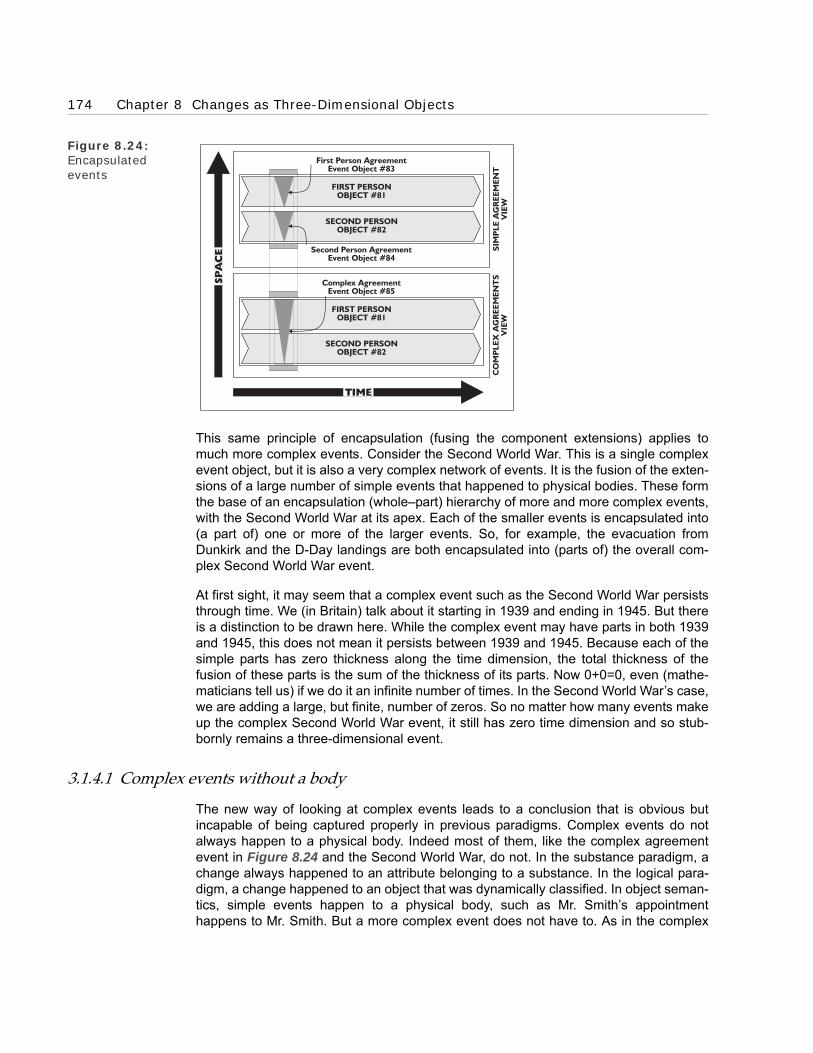
174 Chapter 8 Changes as Three-Dimensional Objects
Figure 8.24: Encapsulated events
This same principle of encapsulation (fusing the component extensions) applies tomuch more complex events. Consider the Second World War. This is a single complexevent object, but it is also a very complex network of events. It is the fusion of the exten-sions of a large number of simple events that happened to physical bodies. These formthe base of an encapsulation (whole–part) hierarchy of more and more complex events,with the Second World War at its apex. Each of the smaller events is encapsulated into(a part of) one or more of the larger events. So, for example, the evacuation fromDunkirk and the D-Day landings are both encapsulated into (parts of) the overall com-plex Second World War event.
At first sight, it may seem that a complex event such as the Second World War persiststhrough time. We (in Britain) talk about it starting in 1939 and ending in 1945. But thereis a distinction to be drawn here. While the complex event may have parts in both 1939and 1945, this does not mean it persists between 1939 and 1945. Because each of thesimple parts has zero thickness along the time dimension, the total thickness of thefusion of these parts is the sum of the thickness of its parts. Now 0+0=0, even (mathe-maticians tell us) if we do it an infinite number of times. In the Second World War’s case,we are adding a large, but finite, number of zeros. So no matter how many events makeup the complex Second World War event, it still has zero time dimension and so stub-bornly remains a three-dimensional event.
3.1.4.1 Complex events without a body
The new way of looking at complex events leads to a conclusion that is obvious butincapable of being captured properly in previous paradigms. Complex events do notalways happen to a physical body. Indeed most of them, like the complex agreementevent in Figure 8.24 and the Second World War, do not. In the substance paradigm, achange always happened to an attribute belonging to a substance. In the logical para-digm, a change happened to an object that was dynamically classified. In object seman-tics, simple events happen to a physical body, such as Mr. Smith’s appointmenthappens to Mr. Smith. But a more complex event does not have to. As in the complex
3 Events – a new kind of physical object 175
agreement event in Figure 8.24, its constituent simple event parts each happen to aphysical body, but not usually the same one. As more events are encapsulated into acomplex event, it gets more and more unlikely that they will have a physical body incommon. In other words, it is unlikely that the extensions of all the individual eventswould be temporal parts of a single physical body. Typically, they are spread over anumber.
These complex events without bodies have interesting repercussions for current O-Oprogramming languages (OOPLs). Methods are, in some ways, OOPLs equivalent ofevents and ‘objects’ its equivalent of bodies. In most OOPLs, methods are firmly tied to‘objects’ (in the object semantics’ way of speaking, events are tied to bodies). In thisenvironment, complex events, such as the Second World War, have to be squeezedinto the framework. A technique often used is to create a pseudo-object (in our terms, abody) for the event to happen to. So there would be a Second World War ‘object’ for thecomplex Second World War event to happen to. As we have noted in the Prologue, O-O programming is, in some ways, a halfway house with elements of both the substanceand object paradigms; insisting events have to happen to ‘objects’ is one example.
3.1.5 Object-version of state change events and Zeno’s paradox
It would seem that we now have a consistent and coherent picture of what event objectsare and how they have extension. We have seen how events differ fundamentally frombodies. They only have three-dimensional spatial extension, with zero temporal exten-sion—unlike bodies, which have a temporal dimension, and so persist through time.
However, there is a small area left, state change events, with an outstanding problem—Zeno of Elea’s paradox. We first met this paradox in Chapter 4 where we saw how thesubstance paradigm resolved the paradox using the now discredited notion of sub-stance. We looked at it again in Chapter 6, where we saw the problems it caused in thelogical paradigm if change was treated as an object with extension. If we do not see cer-tain types of events in the right way, the paradox appears to cause problems for objectsemantics as well.
We can see why by looking again at the change example in Chapter 6 (see Figure6.21). This assumes that there is a tomato changing colour—from green to red. Theproblem is that the instantaneous colour change has extension, albeit three-dimen-sional, and so has a colour. And the colour cannot be either green or red; otherwise, itwould not be a change.
The object paradigm does not seem to have resolved this problem. The simple eventwe re-engineer from the instantaneous colour change has the same problems as its log-ical predecessor. We need to be more sophisticated in our re-engineering. We need tore-interpret the instantaneous colour change as a complex encapsulation of two events.This is the encapsulation of the completion event of the before state and the creationevent of the after state (illustrated in Figure 8.25). Zeno’s paradox is no longer paradox-ical because the encapsulated event does not have to have a single colour.

176 Chapter 8 Changes as Three-Dimensional Objects
Figure 8.25: Complex event of the tomato chang-ing colour space-time map
3.2 Events, causes and effects
We now have a consistent semantics for events as a new type of physical object. Unlikethe dynamic classifications of the logical paradigm, they are objects, and so they canmake use of the class and tuple patterns. They can be collected into classes orarranged into ordered tuples, just like any other object. They can have whole–part andsuper–sub-class patterns. They have, however, another equally important aspect. Theyare the basis for time-ordered patterns that capture and transform our ordinary notionsof cause and effect. In the patterns, events explain the link between causes and effects.
In object semantics, the cause and effect connections are used to describe and explaina far wider range of patterns than is traditional in modern times. The semantics’ notionof cause has more to do with understanding (and explaining)—the objective of businessmodelling, as we recognised in the Prologue—than operation. It turns out that thisapproach has many similarities with the wide ranging ancient framework for cause orig-inally brought together by Aristotle. We now look at this framework and see how itdevelops into the object paradigm’s.
3.2.1 Aristotle’s approach
Aristotle saw causes as explaining an event, helping us to understand it. So, to us, hisclassifications of cause seem to be explanatory principles; for example, he includeswhat we see as effects (the results or consequences of the event) as causes. He syn-thesised his framework from a number of traditions and the result was four types ofcause or explanation:
• The efficient - that which makes a change happen,
• The material - what the change happens to,
• The formal - what the change results in, and
• The final - the end or purpose of the change.
Aristotle believed all of these were needed to give a proper explanation and criticisedhis predecessors for emphasising some to the neglect of others. A similar criticismcould be made of our modern attitude, which often restricts us to the efficient cause—that which makes a change happen.
To see how Aristotle’s approach works, consider a sculptor who has carved a statuefrom a block of marble. In this case, the types of cause are:
TOMATOOBJECT
#91
RED COLOURSTATE#93
GREEN COLOURSTATE#92
Complex ColourChange Event

3 Events – a new kind of physical object 177
• The sculptor is the efficient cause, because he carves the block of marble into the statue.
• The marble is the material cause, because it is what the change happens to.
• The statue is the formal cause, because this is what the sculptor wanted to carve.
• The sale is the goal or final cause, because the sculptor made the statue to sell.
Aristotle was suggesting that when we describe all four types of cause (as we have justdone here), we are giving a description of everything we need to know to understandthe event.
3.2.2 Object semantics’ approach
In object semantics, Aristotle’s types of cause translate neatly into time-ordered pat-terns involving events. These are the event object’s equivalent of the state object’s time-ordered patterns we looked at earlier. As with the state object’s patterns, we can illus-trate the patterns with space-time maps.
Look at Figure Figure 8.26. It is a space-time map for the sculptor carving a statue—with an additional event, the sale of the statue by the sculptor. To make the patternsmore visible, we assume that the complex encapsulated process of carving the statueand the sale are both simple instantaneous events. (People versed in current O-O think-ing can see this as the business modelling’s equivalent of OOPL’s ‘information hiding’.The cause is a connection with the complex encapsulated event not its simple parts.)
Figure 8.26: Sculptor carving a statue space-time map
Each of Aristotle’s four types of change appears in the space-time map. Their links tothe carving event are illustrated with arrows. Underlying each arrow is a pattern of con-nections between the extensions of the objects involved in the statue carving event.
BLOCK OF MARBLE#102
SCULPTOR#101
STATUE#103
MATERIAL CAUSE
EFFICIENT CAUSE
FORMAL CAUSE
FINAL CAUSE
CarvingEvent #104
Statue SaleEvent #105

178 Chapter 8 Changes as Three-Dimensional Objects
The efficient cause is the sculptor who carved the statue. In more modern terminology,the sculptor is a pre-condition for the carving event. This is analysed as a tuple betweenthe sculptor physical body and the carving event (the couple belonging to the causetuples class). In time ordering terms, the sculptor physical body extension must ‘existbefore, during and after’ the carving event extension.
The formal cause is the statue that is a result of the carving event. In modern terminol-ogy, the post-condition of the carving event. This is analysed as a connection betweenthe carving event and the statue physical body. The carving event is a complex (encap-sulated) event. The statue is a state object of the marble object, whose creation event ispart of the carving event. This means the connection between the statue and the carv-ing event is one of overlapping parts.
The material cause is the block of marble that is carved. This is also a pre-condition forthe carving event, though one with a different time pattern to the efficient cause. This isanalysed as a connection between the block of marble and the carving event. The con-nection has an overlapping pattern because the block of marble contains the statueobject’s creation event, which is part of the carving event. Like the efficient cause pre-condition, the block of marble extension must ‘exist before, during and after’ the carvingevent extension.
Object semantics leads to a counterintuitive situation for the material cause, where thecause connection pattern is also a whole–part pattern. The cause is a couple, <block ofmarble, statue>, which belongs to the cause tuples class. This couple also belongs tothe whole–part tuples class, because, as we can see from the space-time map, thestatue is part of the block of marble. In other words, the connection is both cause andwhole–part. We instinctively differentiate between cause with its roots in time andwhole–part with its root in space. However, as this example shows, in space-time ourinstinctive reactions are misleading.
Last, the final cause is the eventual sale of the statue. This is analysed as a connectionbetween the carving event and the sale event. In time ordering terms, the carving event‘precedes’ the sale event. There are also other less important patterns; for instance, ele-ments of the sale event are part of the efficient cause and the material cause.
This shows how working out the Aristotelian causes is part of the overall task of map-ping the sense of an event. When we analyse the pattern of connections between theextensions of the objects involved in the statue carving event, we naturally unearththem. This also shows that Aristotle and his predecessors intuitively understood thephysical time patterns that object semantics make explicit. Their categorisation reflectsthe various aspects of the different underlying time patterns that explain the event. It byno means exhausts the time patterns that occur, but it does give us some idea of themost common patterns. It also gives us a feel for how analysing the patterns of connec-tions between extensions can explain an event.

4 The time-based ‘consciousness’ of information systems 179
4 The time-based ‘consciousness’ of information systems
One of the prime characteristics of the object paradigm is the time-less nature of itsobjects. They give us an ‘objective’ view, independent of any particular information sys-tem at any particular time. This is an extremely powerful way of seeing the world. How-ever, there is one aspect of an information system that cannot, whatever we do, becaptured in a totally timeless way. This is its shifting position in time. From the informa-tion system’s perspective, its ‘consciousness’ exists at a point in time that is movinginexorably along the time dimension.
Computer systems are information systems and so they have a time-based ‘conscious-ness’. They reflect this in their information; when the computer system’s ‘conscious-ness’ is in the 24th May 1999, the leg of a deal that settles on the 25th May 1999 isclassified as awaiting settlement. When its consciousness moves onto the 25th May1999, it is re-classified as due today. This is a change in the computer’s ‘conscious-ness’; nothing has happened to the settlement. We need to be able to capture this in ourbusiness models.
4.1 The dynamic ‘here’ event
We do this by introducing a new kind of class object—the dynamic class or dynaclass.To reflect the information system’s consciousness moving down the time dimension, weuse the dynamic ‘here’ event class. To explain what this object is, we first need to iden-tify the system itself. It is a simple physical body, the four-dimensional extension of thesystem. We can then construct the new type of object that represents the moving con-sciousness—the dynamic ‘here’ event class. It is a class with a single member, thethree-dimensional time-slice of the system at the instant of time that the consciousnessis aware of. The time-slice’s zero length time dimension makes it an event.
Figure 8.27: The dynamic ‘here’ event class space-time map
#113#112
SYSTEMOBJECT#111
SYSTEMOBJECT#111
Here Object#113
Here Object#112
25th25th 26th26th
HERE EVENTCLASS #110
HERE EVENTCLASS #110

180 Chapter 8 Changes as Three-Dimensional Objects
This event behaves in a similar way to the three-dimensional extensions of physicalbodies in the logical paradigm. As the system’s consciousness moves down the timedimension, the ‘here’ event class dynamically changes its member to the system’s cur-rent three-dimensional time-slice. It is called dynamic because, unlike other objects, itchanges. Two ‘versions’ of the dynamic ‘here’ event class are illustrated in the system’sspace-time map in Figure 8.27.
4.2 The dynamic ‘now’ event and the dynamic ‘current’ tuples class
We need to find a way to link the dynamic ‘here’ event class to non-dynamic objects.We do this through another dynamic class,—the ‘now’ event class. This is also a classwith a single member, the instant that the ‘here’ member event occupies—in otherwords, the whole of space for that instant. Like the ‘here’ event class, it is dynamic, withits member tracking the system’s consciousness.
Once we have the ‘now’ event class, we can use it to construct a dynamic current tuplesclass for any class of physical objects. Consider, for example, the class cars. Some ofthe members of this class will exist now. Speaking timelessly, they have a temporal partthat is part of the now object. For each of these cars we can construct a couple, <now,car> (illustrated in the space-time map in Figure 8.28). All these couples belong to thecurrent tuples class. Those cars that do not overlap with the now object, do not have acouple in the current tuples class.
Figure 8.28: The dynamic cur-rent tuples class space-time map
The current tuples class is dynamic, because one of the places of its couple is dynamic,making the couple dynamic and so the class it belongs to. These dynamic couples pro-vide us with the link between the time-bound ‘consciousness’ of the system and thetimeless world of object semantics.
4.3 Implementing dynamic (state) classes
The objective of business modelling is understanding and so I try to keep the dynamicclasses to a minimum. However, when building the system, there may be good opera-
#124 #122
#123
SPACE-TIME#121
CAR #122
NOW CLASS #124
CURRENT TUPLES
NOW OBJECT#123

5 A new way of seeing changes—a key type of thing 181
tional (as opposed to understanding) reasons for designing dynamic classes for imple-mentation. For example, a system may only need to keep a record of all the currentstate objects and have no interest at all in historical state objects. In this case, imple-menting a dynamic class that only reflects the current state makes sense. It would be awaste of information storage space to hold details of the previous states. However, wedo not have to consider these issues when constructing the business model.
5 A new way of seeing changes—a key type of thing
This chapter provides us with a revised semantics for the fourth and final key type ofthing—changes. Unlike previous paradigms, the object paradigm brings changes explic-itly within its remit. Changes are event objects and share the patterns common toobjects.
This is a radical change;, one that, as we expect by now, requires a completely new wayof seeing, thinking and talking about things. This enables us to see the world moreaccurately. The tyre component example illustrates this (see Figure 8.14). Where,under the logical paradigm, we would see a tyre as simply a part of a car, object seman-tics reveals a more accurate and sophisticated pattern of overlapping parts.
Furthermore, the new way of seeing is really new. Unlike the logical paradigm’s ‘mem-ber of’ and ‘part of’ patterns that have begun to work their way into ordinary everydaylanguage, object semantics has made next to no inroads.
Object semantics’ timeless view of the world has had some impact. Expressions like‘time-line’ for four-dimensional objects have been imported from Einsteinian physics.But we still see and talk of them in a time-oriented way. We talk of things moving downtheir time-line, bringing time into the four-dimensional world. Furthermore, most peoplestill think of a period of time starting and ending. They do not see it as a physical bodycontaining all of space for period of time. They certainly do not see an hour as a physi-cal object that is a spatio-temporal part of a day object, though they may talk of hoursbeing ‘in’ a day.
Otherwise, there is very little evidence of object semantics impact on everyday lan-guage. There are no words for:
• An event as an instantaneous time-slice of a four-dimensional object,
• A complex event as a fusion of extensions of simpler events, and
• An instant as a time-slice through space-time.
This is hardly surprising. Object semantics is under a hundred years old and things asfundamental as semantics can take much longer to work themselves into the popularconsciousness.
We can talk about objects in a timeless way by twisting our language. The traditionalway of dealing with time in language is through tenses. We can describe the timelessfour-dimensional world in a tenseless way by only using one tense, the present tense.We can start saying sentences such as ‘the well state extended along the time dimen-sion as far as 25th May’. We have done this, to some extent, in this chapter.

182 Chapter 8 Changes as Three-Dimensional Objects
6 What’s next
This discussion of language leads neatly onto the subject of the next chapter. Languageis not a suitable format for describing a formal and sophisticated semantics, such as theobject paradigm, with any accuracy. Once people start seeing and thinking in the newobject-oriented way, they need an accurate means of modelling their four-dimensionalworld. That is the topic of the following chapters in Part E. There we will look at theobject syntax, and its notation, that together with object semantics form the object para-digm. People generally find that working through this gives them a more ‘substantial’feel for object semantics.

BOROBORO
Part EConstructing Signs for Business Objects
Chapter 9 Constructing Signs for Business Objects
Chapter 10 Constructing Signs for Business Objects’ Patterns


BOROBORO
Chapter 9Constructing Signs for Business
Objects
1 Introduction
2 Constructing signs for individual objects
3 Constructing signs for classes of objects
4 Constructing signs for tuples
5 Constructing signs for whole–part tuples
6 Constructing signs for dynamic objects
7 Signs as objects—modelling the model
8 What’s next

186 Chapter 9 Constructing Signs for Business Objects
1 Introduction
In Part D, we developed an understanding of what business objects are. However, thatwas only a precursor, albeit an important one, to the real business of modelling. Theaccuracy and flexibility of object semantics give us a powerful way of seeing the busi-ness. We harness this power by building models that describe what we see.
Here, in Part E, we focus on object syntax—in other words, on how we ‘write’ the signsfor objects and their patterns. We learn a notation for describing business objects inmodels. In this chapter we look at the individual signs for the main types of businessobject. These are the signs with which we build the business object model. We focus onwhat they mean and how they work. Then, in the next chapter, we look at signs for busi-ness objects’ patterns.
Together Part E’s two chapters help us to develop an understanding of object syntaxand the notation for business object models. They also deepen and broaden our under-standing of object semantics. Using a notation for describing objects naturally leads to abetter understanding of them. For example, because the notation explicitly signs the keystructural patterns (super–sub-class, class–member and whole–part) these are clearlyvisible and so easier to understand. And because the notation gives each pattern a dif-ferent sign, it helps us see that they are different.
Learning this notation is essential for Part F, where we work our way though examplesof re-engineering existing computer systems into business objects. As well as providinguseful illustrations of both object semantics and object syntax, these examples will pro-vide us with further experience of how the notation is used.
1.1 Main types of business object
In this chapter we look at the object notation’s basic signs for the following main types ofobject:
• Individual objects,
• Class Objects,
• Tuple objects (and, more specifically, whole–part tuple objects), and
• Dynamic objects.
We see how the signs are constructed, what they mean and how they are used.
1.2 Why use a two-dimensional notation for a multi-dimensional model?
Before we look at the notation, I should explain why it is two-dimensional. I haveasserted a number of times that objects free us from the two-dimensional constraintsimposed by paper and ink technology. I have suggested that this enables us to takeadvantage of computer technology’s ability to handle multi-dimensional structures.However, the notation we are about to look at is on paper and so only two-dimensional.Why is this so and why doesn’t it constrain the overall business model to two dimen-

2 Constructing signs for individual objects 187
sions? To understand the answers to these questions, we need to look closely at the‘technology’ that we use when business modelling.
Modelling the business is currently done by humans. It is human brains, and not com-puters, that construct and revise the business model. This means that the human mindneeds to ‘interface’ with the business model. The object notation has to be easily readby humans.
Human biotechnology and computer technology both constrain how we can ‘process’ abusiness model. (Processing currently means ‘see’—we do not touch or hear businessmodels, let alone taste or smell them.) Computer technology constrains our visual ‘inter-face’ to two dimensions. The ‘inputs’ we receive from a computer system, whether on ascreen or a print-out, are two-dimensional. The biotechnology of human eyes’ retinas isalso constrained to two-dimensional images. Furthermore, human brains are trained toprocess the kind of information in business models on two-dimensional surfaces.
From a practical point of view, this means that the sensible solution is to construct andreview the multi-dimensional business model through two-dimensional views. Digestibletwo-dimensional chunks are an easy and effective way for the human brain to absorbthe model. And its multi-dimensionality is not affected.
This solution can give computer technology an important role. Business models arestatic—in both traditional and object modelling; they map the time dimension onto thespatial dimensions. This means that the business model is not itself an information pro-cessing system; it is only stored information—data. However, producing a two-dimen-sional view of a multi-dimensional business model does take processing. So, at least intheory, we need the power of a computer to store the multi-dimensional model and pro-duce the two-dimensional views.
In practice, using a computer with good CASE tool software can make the administra-tion of storing the model and the processing of views easier, but it is not essential. Ihave found that constructing a multi-dimensional business model from two-dimensionalpaper views (in other words, using paper and ink technology) is a practical option—par-ticularly when working with small models. The vital decisions about the construction andreview of the business model happen in the brain of the business modeller, which is notexcessively hampered by a paper model.
This is just as well because CASE tool software is not yet fully geared up for businessobject modelling. At a more mundane level, I have found a computer graphics packagean invaluable aid to producing the paper views; the results are much more legible thanhand-drawn ones. While computers are not essential at the business modelling stage, itis a different story when the model is turned into a working system. Then, computertechnology becomes essential.
2 Constructing signs for individual objects
Let’s now look at the two-dimensional notation. In object semantics, an individual objectis a plain and simple extension. This is referred to (directly mapped onto) by a sign in

188 Chapter 9 Constructing Signs for Business Objects
the model. We use different signs for the different types ofindividual objects:
• Individual body, and
• Individual event.
2.1 Constructing a sign for an individual body
The sign for an individual body is constructed out of two components. A body sign,which is a rectangle, and a name sign that is the name of the body. We put the namesign inside the body sign (shown in Figure 9.1). This figure also diagrams the extra-model reference link between the individual body sign in the model and the body objectin the domain.
Figure 9.1:Individual body sign
Sometimes, to aid recognition, we include an icon of the individual body inside the bodysign (shown in Figure 9.2).
Figure 9.2: Alternative individ-ual body sign
refe
rs t
o
MY CARMY CAR
Individual BodyName Sign
CompositeIndividualBody Sign
BodyComponent Sign
+ =
INFO
RM
AT
ION
MO
DEL
CO
MP
ON
EN
TSIG
NS
DO
MA
IN
refe
rs t
o
IndividualBody NameComponent
CompositeIndividualBody Sign
ComponentBody Sign
IndividualBody Icon
Component
MY CAR
MY CAR
INFO
RM
AT
ION
MO
DEL
DO
MA
IN
CO
MP
ON
EN
T S
IGN
S

3 Constructing signs for classes of objects 189
2.2 Constructing a sign for an individual event
We construct the sign for an individual event in a similar way out of two components. Anevent sign, which is an ellipse, and a name sign, which is the name of the event. Weagain put the name sign inside the event sign (shown in Figure 9.3).
Figure 9.3: Individual event sign
2.3 Constructing individual object name sign components
The shape of the component body and event signs show their type; so, all signs of thesame shape are the same type. We use everyday language for the name components.These differentiate between signs for different objects. They help us recognise whichobject a particular composite sign refers to. To avoid confusion, a convention, withineach model, indicates that the name signs are unique; no two individual objects havethe same name sign.
3 Constructing signs for classes of objects
We now look at how to construct the signs that refer to classes. We also look at thesigns for the class pattern’s two important tuples connecting classes:
• Class–member, and
• Super–sub-class.
3.1 Constructing a sign for a class of individual objects
We first look at how to construct a sign for a class of individual objects. Just as there aredifferent signs for an individual body and an individual event, there are different signs fora class of individual bodies and a class of individual events.
Individual EventName Sign
CompositeIndividualEvent Sign
Event Component Sign
refe
rs t
o
ACCIDENT ON25/5/95
ACCIDENT ON25/5/95+
INFO
RM
AT
ION
MO
DEL
DO
MA
IN
CO
MP
ON
EN
TSIG
NS

190 Chapter 9 Constructing Signs for Business Objects
3.1.1 Constructing a sign for a class of individual events
Remember that we construct a class of individual objects by collecting together theextensions of those objects and treating the collection as a single object. This singleobject is what the class sign refers to.
A class of individual events only contains events, so we use the same elliptical eventsign as a component. We put the name of the class in this ellipse. We then indicate thatwe have constructed the event class out of individual events by putting two smallersuperimposed ellipses—signs for the member events—in the bottom right corner. Fig-ure 9.4 gives an example. In this example, we have also put the name sign for a mem-ber of the class, ‘accidents’, in the smaller ellipse. Often, however, a member name signtakes up too much space and we have to leave it out.
Figure 9.4: A class of individ-ual events sign
3.1.2 Constructing a sign for a class of individual bodies
The sign for a class of individual bodies follows the same pattern. We use the same rec-tangular box sign that we used for individual body signs and show the class has mem-bers using two smaller superimposed rectangular boxes in the bottom right corner.Again we name the class and, if there is enough space, the potential members. Thename sign for the class is in the larger class rectangle and the name sign for a memberof the class is in the smaller member rectangles (shown in Figure 9.5).
INFO
RM
AT
ION
MO
DEL
DO
MA
IN
ACCIDENTS
ACCIDENT ACCIDENT
ACCIDENT
CompositeClass Of
IndividualEvents Sign
MemberName Sign
Composite EventMembers Sign
Event MembersComponent Sign
Event ClassName Sign
EventComponent Sign
+
+ +
=
CO
MP
ON
EN
T S
IGN
S
ACCIDENTS
ACCIDENTS
ACCIDENT
refe
rs t
o

3 Constructing signs for classes of objects 191
Figure 9.5: A class of individ-ual bodies sign
3.1.3 Constructing class name and member name sign components
We use class names, as we used individual object names, to differentiate the signs (andso identify the classes). As before, we keep the names unique within each model.Unlike some notations, we use different names for a class and its members. Theseother notations, will, for example, call both the cars class and its individual members‘car’. I have found that this causes confusion. In object semantics, a clear distinction ismade between the class and its members. In object syntax, this is reflected in differentnames for the class and its members— often, as here, the plural and singular forms of anoun. Using the car example, the class is called (and so the class name sign is) ‘cars’and an individual member is called a ‘car’.
3.2 Constructing a sign for a class–member tuple
Individual objects (whether bodies or events) that are members of a class belong to thatclass; that is, there is a class–member tuple connecting each member object and theclass. This tuple is central to the notion of a class, so we need to have a sign for it in ournotation.
3.2.1 Classes and members
The class–member tuple is, strictly speaking, a couple <individual object, class> thatbelongs to the class–member tuples class. We model it by drawing a class–membertuple sign. This is a dashed line joining the relevant class and member signs. It has, atthe member end, a semi-circle with a line through it (shown in Figure 9.6). This isintended to look like the Greek character epsilon ‘ε’—the mathematical sign for class
Member Name Sign
Bodies ClassName Sign
CompositeBody Members
Sign
Body MembersComponent Sign
CompositeBodies Class
Sign
ComponentBody Sign IN
FO
RM
AT
ION
MO
DEL
DO
MA
IN
CARS
CAR
CAR
CAR
+ +
+ =
CO
MP
ON
EN
T S
IGN
SCARS
CARrefe
rs t
o

192 Chapter 9 Constructing Signs for Business Objects
membership. We show that the connection is a tuple by putting a black diamond, thesign for a tuple, on the line.
Figure 9.6: Class–member tuple sign
Figure 9.7: Multiple class–member tuple signs
As you can see from the figure, we use the same class–member tuple sign for body andevent classes. This is understandable because the underlying pattern is the same.There is also an informal convention (followed in Figure 9.6) that we draw classeshigher up the page than their members; though in some complicated diagrams, it is notpossible to do this.
3.2.1.1 Members of more than one class
Unlike some notations, this can easily model an object that is a member of more thanone class—what we called multiple classification. We just join the object’s sign to eachof the relevant class signs with class–member tuple signs (shown in Figure 9.7).
MY CAR
CARS
CAR
BODY EXAMPLE EVENT EXAMPLE
ACCIDENTS
ACCIDENT
ACCIDENT ON25/5/95
CompositeClass-MemberTuple Sign Tuple
ComponentSign
Class-Member TupleComponent Sign
MY CAR
MY THINGS
MYTHING
Multiple Class-MemberTuples CARS
CAR
refe
rs t
o
INFO
RM
AT
ION
MO
DEL
DO
MA
IN
MYTHINGS
refe
rs t
o
CARS
refe
rs t
o

3 Constructing signs for classes of objects 193
3.2.1.2 An accurate class–member sign pattern
The class–member pattern is a very strong pattern; one that is central to object seman-tics. So is its reflection in the information model, the class–member sign pattern.Because one is a reflection of the other, they have similar patterns. However, a commonmistake is to assume they have the same pattern. This is not so. The informationmodel’s ‘ignorance’ leads to differences. We look at one of these now.
It is natural and normal to assume a class has members. A class is a class because itcaptures some common patterns of its members; so, it is reasonable to assume it hasmembers. Because a class sign’s purpose is to model a class, it also appears reasona-ble to assume that it will reflect this characteristic—to think that a class sign is alwayslinked to some member signs (sometimes called instances).
But this is wrong—it turns out that it is natural and normal in an information system for aclass sign to have no member signs. In fact, it is quite common. For example, we talkabout types of wild animals without having any notion of a particular animal. We talkabout elephants (the class elephants) or gorillas (the class gorillas) without ever know-ing a particular elephant or gorilla (members of the classes elephants and gorillas). Ourminds, as information systems, have no member signs for the class signs we are using.
Member sign-less (instanceless) class signs are an almost universal rule in the shippedversions of business computer system packages. For example, accounting packagesare usually shipped with a transactions file (a class sign) that has no individual transac-tions (in object terms, member signs)—the situation shown in Figure 9.8.
Figure 9.8: The instanceless transactions class sign
3.2.2 Modelling lack of membership information
No information system is completely ‘informed’. This includes human minds, which areconsidered information systems. We now illustrate this with two types of ignorance thatarise when modelling the class–member pattern:
• Unknown members, and
INFO
RM
-A
TIO
NM
OD
EL
DO
MA
IN
TRANSACTIONS
refe
rs t
o
TRANSACTIONS
TRANSACTION

194 Chapter 9 Constructing Signs for Business Objects
• Unknown membership.
Figure 9.9: Known and unknown class–members
3.2.2.1 Modelling unknown members
For every class in an information system, when we look at it objectively from outside thesystem, we can divide its members into known and unknown. Known if the informationsystem has a sign for them; otherwise, unknown (or, more accurately, unknown by theinformation system but known by us—otherwise, we could know that they wereunknown). This distinction has nothing to do with the class or its members. It is a featureof the information model (shown in Figure 9.9.)
It is common for a member to be unknown because it has not yet come into existence.When it does, the information system can then construct a sign for it. This happens, forinstance, when a new country is created. It happened recently for the Czech Republicand Slovakia; ten years before they were created, no-one would have known aboutthese two countries. But when Czechoslovakia decided to separate into two countries,people began to become aware of them. The extension of the class countries in the realworld did not change. All that changed was the construction of new signs for the CzechRepublic and Slovakia in information systems.
3.2.2.2 Modelling unknown class membership
It is important to remember that, not only do signs have to be constructed in the systemfor the class’s members, but also for the class–member tuples connecting members tothe class. Our minds automatically and unconsciously supply this link; so, it is easy toforget that it needs to be explicitly constructed. We can illustrate this with an examplewhere the system starts off knowing about the member of a class but not its member-ship of the class.
INFO
RM
AT
ION
MO
DEL
DO
MA
IN
KNOWN
UNKNOWN
refe
rs t
o
refe
rs t
o
refe
rs t
o
refe
rs t
o
? ?JOHN'S CARMY CAR
CARS
refe
rs t
o
CARS
CAR

3 Constructing signs for classes of objects 195
Figure 9.10: Jeeves the butler as an unknown member of the class murderers
Consider an Agatha Christie type of detective novel, in which a murder has been com-mitted in a country house. At the beginning of the novel, we are introduced to each ofthe characters; the butler, the lord of the manor, the chambermaid, and so on. We knowthat, by convention, one of these is the murderer. Assume that Jeeves the butler is themurderer—in other words, a member of the class of murderers. Now, when we startreading the book we know Jeeves and know the class murderers, but have not (yet)found out that Jeeves is a member of the class murderers. Figure 9.10 shows the stateof our knowledge.
Figure 9.11: Jeeves the butler as a known mem-ber of the class murderers
refe
rs t
o
refe
rs t
o
JACK THERIPPER
INFO
RM
AT
ION
MO
DEL
DO
MA
IN
JEEVES
MURDERERS
refe
rs t
o
MURDERERS
MURDERER
BUTLERS
refe
rs t
o
BUTLERS
BUTLER
refe
rs t
o
refe
rs t
o
JACK THERIPPER
INFO
RM
AT
ION
MO
DEL
DO
MA
IN
JEEVES
MURDERERS
refe
rs t
o
MURDERERS
MURDERER
BUTLERS
refe
rs t
o
BUTLERS
BUTLER

196 Chapter 9 Constructing Signs for Business Objects
At some stage, as the plot unfolds, we realise the butler is the murderer. As we alreadyhave signs for the butler and the class murderers, all we need to do is construct theclass–member tuple sign between the two. The result is shown in Figure 9.11. Noticethat there is no change in the domain. The butler belonged to the class murderers allalong, what happens when we solve the mystery is that we learn of his membership.
3.2.2.3 The constructive nature of modelling
This and the previous example of ‘ignorance’ have highlighted what might be called theconstructive nature of signs and so information. Signs only exist if we construct them.This is obvious when we start to think about it. How could a sign exist that has not beenconstructed? We shall see, as we work through this chapter, the fundamental impactthis constructive nature has on information modelling.
3.2.3 Classes as members of classes
So far we have only considered classes of individual objects. However, we recognisedin the logical paradigm that classes were objects and so could, like individual objects,be collected together into classes—giving us classes of classes objects. This meansthat the class–member tuple, with its <class, member> format, can have any type ofobject (individual, class or tuple) in its member place. We now look at how we sign theclass-member pattern for classes of classes, and, in the process, see how we captureclass–member hierarchy patterns in the model.
Figure 9.12: Car types—an example of a class–member hierarchy
3.2.3.1 Class–member hierarchy
The sign for describing a class as a member of a class is exactly the same as that fordescribing an individual object as a member of a class. The example shown in Figure9.12 is taken from our original example of classes of classes in Chapter 6 (illustrated byFigures 6.8 and 6.9). As we can see, the class–member sign is used in the same wayfor members that are classes as for members that are individual objects. Figure 9.12 isalso an example of how we model a simple class–member hierarchy.
CAR TYPES
CAR TYPE
MINIS
MINI
MY CAR
CLASS OF CLASSES OBJECT
CLASSOBJECT
INDIVIDUALOBJECT
CLASS-MEMBER
HIERARCHY
InvalidClass-MemberInheritance{

3 Constructing signs for classes of objects 197
3.2.3.2 Class membership inheritance
We shall see later on that various patterns are inherited down (and sometimes up) thedifferent hierarchies. However class membership is not one of these. It is inherited nei-ther up nor down the class–member hierarchy. Consider my car in Figure 9.12. It is amember of the class minis, which is itself a member of the class car types. But this doesnot imply that my car is automatically a member of the class car types. In fact, asshown, it is not a member.
This should not be surprising. Classes capture patterns by collecting together similarobjects. It is unlikely that a collection of similar classes, such as car types, would sharetheir car type pattern with their members. For example, that my car (a member of minis)would behave like a car type.
3.2.3.3 Ban on circularity
Because we construct classes from extensions, we cannot construct a class with itselfas a member. Furthermore, we cannot construct a class that is a member of a classlower down the class–member hierarchy. The impossible situation is shown in Figure9.13. We recognise this impossibility in the information model. We do not allow classsigns to be instances of class signs lower down the class–member sign hierarchy.
Figure 9.13: Impossible circular class–member hierarchy
It is the nature of our understanding of space (and time and space-time) that makes thiscircularity impossible. This can be shown using the reference diagram in Figure 9.14.
3.3 Constructing a sign for a super–sub-class tuple
We have just looked at the signs for capturing the class–member patterns. However,this is only one of class’s two main structural patterns. The super–sub-class connectionis the other. We now look at the signs for this second main structural pattern. Togetherthese two provide a framework that helps give classes their enormous power.
3.3.1 The super–sub-class pattern
The super–sub-class pattern resembles a whole–part pattern for classes. It is aboutclasses containing other classes. For example, horses are animals—or, in class-speak,
CAR TYPES
CAR TYPE
MINIS
MINI

198 Chapter 9 Constructing Signs for Business Objects
the class horses is a sub-class of (is contained in) the class animals. This containmentor sub-class connection is between the super-class and the sub-class. Strictly speaking,it is the couple <super-class, sub-class> that belongs to the super–sub-class tuplesclass.
Figure 9.14: Impossible circular class–member hierarchy refer-ence diagram
3.3.1.1 Super–sub-class sign
We model this super–sub-class pattern with a sign. It consists of a line joining the tworelevant class signs with a semi-circle at the sub-class end. This is intended to look likethe mathematical notation for sub-class. Because it reflects a tuple, it also has a blackdiamond tuple sign on the line. As we can see from Figure 9.15, the same sign is usedfor body and event classes. There is no need for different signs because the connec-tions have the same pattern.
Figure 9.15: Super–sub-class tuple sign
INFO
RM
AT
ION
MO
DEL
DO
MA
IN MINIS
CAR TYPES
CAR TYPES
CAR TYPE
MINIS
MINI
CAR TYPES
MINIS
refe
rs t
o
refe
rs t
o
ANIMALS
ANIMAL
HORSES
HORSE
SERIOUSACCIDENTS
SERIOUSACCIDENT
CompositeSuper-Sub-Class TupleSign
TupleComponent
Sign
Super-Sub-ClassTuple Component Sign
BODY EXAMPLE EVENT EXAMPLE
ACCIDENTS
ACCIDENT

3 Constructing signs for classes of objects 199
3.3.2 Super–sub-class hierarchies
Typically, in a business model, classes are linked into a lattice hierarchy of super- andsub-classes. As we saw, when looking at the logical paradigm in Chapter 6 (see Figure6.3), a tree hierarchy is too constraining to provide an undistorted reflection of reality.
Figure 9.16: Natural super–sub-class hierar-chy structure
3.3.2.1 Natural super–sub-class hierarchy structure
In this lattice hierarchy, a super-class may have multiple sub-classes and a sub-classmay have multiple super-classes. For instance, the schema in Figure 9.16 models thesuper-class animals as having the sub-classes, mammals and male animals. It modelsthe class stallions as having the classes horses and male animals as its super-classes.
When I construct a model of a super–sub-class hierarchy like this, I tend to automati-cally order the classes into a structure like the one in Figure 9.16. As you can see, thisfollows an informal convention whereby super-classes are higher up the page than theirsub-classes (though I find that in some complicated hierarchies it is not possible to dothis).
3.3.2.2 Modelling descendant–sub-classes
The natural structure in Figure 9.16 subtly ignores the fact that the super–sub-classtuple can be inherited. The class stallions is a sub-class of the class horses and so con-tained in it. The class horses is a sub-class of the class mammals, which is a sub-classof the class animals. So, the class stallions is contained in the class animals. Thismeans that we can, if we wish, recognise it as a sub-class and construct a sub-classsign in the model linking them.
Though we may need to do this for some classes, it is not a good idea to do it for all ofthem in a single schema. Why is this? Consider what the model for our simple examplewould look like if we included signs for all the possible sub-class tuples.
MALEANIMALS
MAMMALS
MAMMAL
HORSES
HORSE
STALLIONS
STALLION
ANIMALS
ANIMAL

200 Chapter 9 Constructing Signs for Business Objects
Figure 9.17 illustrates the problem—the hierarchy becomes cluttered. If the super–sub-class hierarchy were larger, the problem would be worse because the number of poten-tial sub-class tuples would increase dramatically. Modelling all these possible sub-classtuples would result in an impossibly cluttered schema.
Figure 9.17: All possible sub-class tuples
Figure 9.17 also, quite usefully, distinguishes between two types of sub-class tuples;child and descendant. The stallions-to-horses tuple is a child–sub-class tuple becausethere are no intermediate sub-classes explicitly modelled. On the other hand, the stal-lions-to-animals tuple is a descendant–sub-class tuple because the sub-classes, mam-mals and horses, are explicitly modelled as intermediate sub-classes. The sub-classsign we have been using until now is really the sign for the child–sub-class tuple. Thedescendant–sub-class tuple sign is a modified version of it, with an additional zigzag inits line (as shown in Figure 9.17).
3.3.2.3 Deducing descendant–sub-class signs
Descendant–sub-class tuples logically depend on child–sub-class tuples, because wecan ‘logically’ construct their signs from the signs for the child–sub-class tuples. Moregenerally, we can logically deduce the sign for a descendant–sub-class tuple from acombination of sub-class tuples. This deduction has the following pattern:
A is a sub-class of BB is a sub-class of CC is a sub-class of DD is a sub-class of ETherefore: A is a descendant–sub-class of E
Where there can be any number of sub-class lines (except zero and one of course).
This is not a new logical deduction pattern. It is the same as one of Aristotle’s syllo-gisms—one that looks like this:
All Spartans are humans,All humans are animals,So all Spartans are animals.
MALEANIMALS
MAMMALS
MAMMAL
HORSES
HORSE
STALLIONS
STALLION
ANIMALS
ANIMAL
Child-Sub-ClassTuple
Descendant-Sub-Class
Tuples
CompositeDescendant-Sub-Class Tuple Sign
Descendant-Sub-Class Tuple
ComponentSign

3 Constructing signs for classes of objects 201
It might be easier to see the resemblance when the syllogism is translated into class-speak—as below:
The class Spartans is a sub-class of the class humans,The class humans is a sub-class of the class animals,So the class Spartans is a descendant–sub-class of the class animals.
Figure 9.18 shows this descendant calculation graphically.
Figure 9.18: Descendant–sub-class calculations
3.3.2.4 Virtual descendant–sub-class signs
This descendant deduction pattern provides an opportunity to tidy up the sub-class clut-ter problem. The descendant signs can be virtual, calculated as required. As we dis-cussed in Chapter 2, there is no reason why processes in the information systemcannot represent business objects. This gives us the benefit of having signs for all thedescendant–sub-class tuples without having to bear the cost of storing them—a signifi-cant compacting.
The power of computing makes this ‘virtual’ strategy more reliable. In a paper and inkenvironment, the information processor that deduces the descendant tuple signs is ourminds. They are not particularly reliable processors, particularly of these sorts of logicalcalculations. However, in computer processing, we have a reliable logical processor. Itcan accurately and consistently calculate the signs.
I normally adopt a strategy of making most descendant–sub-class signs virtual. I con-struct views of the business model that only show the signs for child–sub-class tuplesand those descendant–sub-class tuples that are essential. I make the signs for theother descendant–sub-class tuples virtual. This reduces the clutter in even the mostcomplicated super–sub-class hierarchy to an easily manageable level.
ANIMALS
ANIMAL
ANIMALS
ANIMAL
HUMANS
HUMAN
HUMANS
HUMAN
SPARTANS
SPARTAN
SPARTANS
SPARTAN
BEFORE AFTER
CalculatedDescendant-Sub-ClassTuple

202 Chapter 9 Constructing Signs for Business Objects
3.3.2.5 Non-circular super–sub-class hierarchy structure
There is a logical constraint upon the super–sub-class hierarchy. Like the earlier class–member hierarchy, it cannot be circular. For example, animals from Figure 9.18 cannotbe a sub-class of Spartans, as (falsely) indicated in Figure 9.19. Because classes arebuilt up out of extensions, it is impossible for any circularity to exist. A class, such asanimals, cannot even potentially, be a sub-class of itself—in other words, contained initself.
Figure 9.19: Impossible circular super–sub-class hierarchy
Like the class–member hierarchy, it is the nature of our understanding of space andtime (and space-time) that makes this circularity impossible. This is shown by the refer-ence diagram in Figure 9.20. Normally, we illustrate the super–sub-class structure byhaving one class contained in another. However, as the figure shows, this will not workfor a circular structure; instead, we show the sub-class connection using an arrow.
Figure 9.20: Impossible circular super–sub-class reference diagram
SPARTANS
SPARTAN
ANIMALS
ANIMAL
HUMANS
HUMAN
INFO
RM
-A
TIO
NM
OD
EL
DO
MA
IN
ANIMALS
refe
rs t
o
ANIMALS
ANIMAL
HUMANS
SPARTANS

3 Constructing signs for classes of objects 203
3.3.2.6 Inheriting class membership
As we would expect, the patterns for classes are webby; in other words, the patterns forsuper–sub-class and class–member intertwine. One pattern is particularly important; itis the inheritance of class membership up the super–sub-class hierarchy.
To see how this works, we introduce Trigger the horse into the model in Figure 9.21.We naturally tend to make him a member of the class stallions (shown in Figure 9.21).Stallions is the hierarchy’s lowest class. However, Trigger is potentially a member of allthe hierarchy’s higher classes, but our natural instinct is not to model these possibilities.
Figure 9.21: Natural position for Trigger the horse
Why don’t we model these potential higher class–member tuples? We had a similar sit-uation to this earlier with child– and descendant–sub-classes. And the answer is thesame here—they would clutter up the schema and the model. We can see this in Fig-ure 9.22, which shows the results of constructing all the class–member tuples for ourexample. The model is pretty cluttered and this is only a small hierarchy. A much largerhierarchy would be impossibly cluttered. We have a class–member, as well as a sub-class, clutter problem.
Figure 9.22 also illustrates a distinction between the sign for the lowest class–membertuple—now called the nearest-class–member sign—and the sign for other class–mem-ber tuples—now called distant-class–member signs. The distant-class–member signsuse the same zigzag component sign as the earlier descendant–sub-class signs. Trig-ger’s nearest class is stallions because there is no class below stallions in the super–sub-class hierarchy to which he belongs; so, the class–member tuple is a nearest-class–member tuple. Trigger is a distant-class–member of each of the classes horses,mammals, male animals and animals because there is a class below them in the class–member hierarchy, the class stallions, of which he is a member.
TRIGGER
MALEANIMALS
MAMMALS
MAMMAL
HORSES
HORSE
STALLIONS
STALLION
ANIMALS
ANIMAL
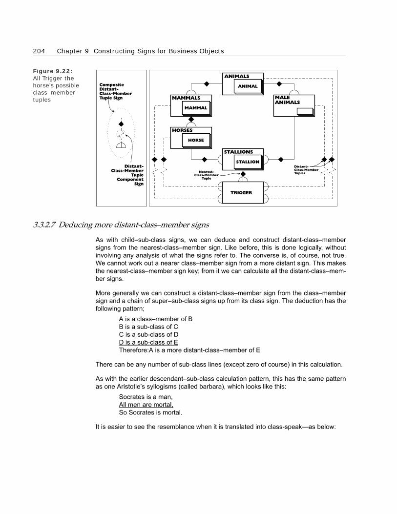
204 Chapter 9 Constructing Signs for Business Objects
Figure 9.22: All Trigger the horse’s possible class–member tuples
3.3.2.7 Deducing more distant-class–member signs
As with child–sub-class signs, we can deduce and construct distant-class–membersigns from the nearest-class–member sign. Like before, this is done logically, withoutinvolving any analysis of what the signs refer to. The converse is, of course, not true.We cannot work out a nearer class–member sign from a more distant sign. This makesthe nearest-class–member sign key; from it we can calculate all the distant-class–mem-ber signs.
More generally we can construct a distant-class–member sign from the class–membersign and a chain of super–sub-class signs up from its class sign. The deduction has thefollowing pattern;
A is a class–member of BB is a sub-class of CC is a sub-class of DD is a sub-class of ETherefore:A is a more distant-class–member of E
There can be any number of sub-class lines (except zero of course) in this calculation.
As with the earlier descendant–sub-class calculation pattern, this has the same patternas one Aristotle’s syllogisms (called barbara), which looks like this:
Socrates is a man,All men are mortal,So Socrates is mortal.
It is easier to see the resemblance when it is translated into class-speak—as below:
Nearest-Class-Member
Tuple
Distant-Class-MemberTuples
TRIGGER
CompositeDistant-Class-MemberTuple Sign
Distant-Class-Member
TupleComponent
Sign
MALEANIMALS
MAMMALS
MAMMAL
HORSES
HORSE
STALLIONS
STALLION
ANIMALS
ANIMAL

3 Constructing signs for classes of objects 205
Socrates is a class–member of the class men,The class men is a child–sub-class of the class mortals,So Socrates is a distant-class–member of the class mortals.
The distant calculation for Aristotle’s syllogism is shown in Figure 9.23.
Figure 9.23: Aristotle’s barbara syllogism
People who have not yet developed a clear idea of the difference between the class–member and super–sub-class patterns often see this distant-class–member calculationprocess as the same as the earlier descendant–sub-class calculation process. Whenthey develop a clear understanding of the differences between the two patterns, theythen begin to see the differences between, as well as the similarities in, the two pro-cesses.
3.3.2.8 Compact class–member hierarchy models
The distant-class–member deduction pattern works in a similar way to the earlierdescendant–sub-class pattern. This provides us with an opportunity to use virtual signsagain and tidy up the class–member clutter problem. An opportunity to get the benefit ofhaving signs for all the descendant–sub-class tuples, without having to bear the cost ofvisibly recording them. Once I model the nearest-class–member tuple, I can assumethat all the distant-class–member tuples also ‘virtually’ exist.
I can then adopt the strategy of only modelling the nearest-class–member tuples andessential distant-class–member tuples. The signs for the many other distant-class–member tuples are virtual. This can reduce the clutter in even the most complicatedclass–member hierarchy to an easily manageable level.
MORTALS
MORTAL
MORTALS
MAN
MEN
MAN
MEN
MAN
CalculatedDistant-Class-MemberTuple
SOCRATESSOCRATES
BEFORE AFTER

206 Chapter 9 Constructing Signs for Business Objects
3.3.3 Super–sub-class tuples class
We naturally see the super–sub-class tuple as connecting classes. This is correct inone sense, the tuple can only connect classes. But, it does not mean the super–sub-class sign only connects class signs. If a class sign refers to a class of classes, then itsmember component refers to the member classes. Because these are classes they canbe connected with their sub-class signs using the super–sub-class sign. Furthermore,because the member component sign refers to a class of members, the super–sub-class sign refers to a class of super–sub-class tuples.
Here is an example. Consider the Linnaean biological scheme used to classify individu-als into species and species into genera (singular—genus). This two-level structure isreflected in the Linnaean names for species. For instance, our species is homo sapienswhere homo is the genus and sapiens the species within genus. This gives us an exam-ple of a super–sub-class tuple class between classes’ members.
At the classes of classes level we have two classes; genera and species. The classgenera has individual genus classes, such as homo as members. The class specieshas individual specie classes, such as homo sapiens as members. At the classes ofindividual objects level, we also have two classes; homo and homo sapiens. The classhomo sapiens is a sub-class of the class homo as shown in Figure 9.24. This particularsuper–sub-class pattern is just a particular example of a more general pattern. Themembers of the class species are sub-classes of the members of the class genera. Thisis a super–sub-class tuples class between the classes’ members. Because it refers toall the different individual tuples between the various members, it is a class of tuples notan individual tuple. This is reflected in its sign, which uses a tuples icon instead of atuple icon (shown in Figure 9.24).
Figure 9.24: The super–sub-class tuples class sign
4 Constructing signs for tuples
We have finished looking at the notation for classes, an object with internal structureresulting from its construction from other objects. We now look at another constructedobject with internal structure, the tuple object.
HOMO
HOMOSAPIENS
SPECIES
SPECIE
GENERA
GENUS
CompositeSuper-Sub-ClassTuples Sign
TuplesClass
ComponentSign
Super-Sub-Class TupleComponent Sign

4 Constructing signs for tuples 207
Figure 9.25: Tuple and tuple class signs
4.1 Constructing a tuple of individual objects and a tuples class
For our purposes, tuples exist with an associated tuples class. So we model the sen-tence ‘Prince Charles is the father of Prince William’ with a tuple and a tuples class(shown in Figure 9.25).
Note these points:
• The solid black diamond is the component sign for the tuple.
• The connecting lines from the tuple component sign to other signs are called tuple place component signs.
• The tuple place component signs connect the sign for the tuple with the signs for the objects out of which it is constructed. These are called the tuple place objects. In the Prince Charles—Prince William tuple, the places are occupied by individual objects, but they could be occupied by any type of object.
• The component sign for a tuples class is two hollow diamonds, one inside the other.
• The lines from the component tuples class sign are called the (tuples) class place component signs.
• The father–child tuples class is a class object and so uses the standard class–member sign to link to its member tuple sign.
4.1.1 Occupied class place signs
A (tuples) class place is said to be occupied when its tuples class sign is connected toanother object. For instance, the fathers class is connected to the father–child tuplesclass in Figure 9.26. This occupation is signed by adding the component tuple sign, asolid black diamond, to the (tuples) class place component sign. The object to which thetuples class is connected is called a (tuples) class place object, an example is thefathers class in Figure 9.26. Notice that the ‘is a child of’ class place sign in Figure 9.26does not have a black diamond component because it is not occupied.
INFO
RM
AT
ION
MO
DEL
DO
MA
IN
refe
rs t
o
refe
rs t
o
PRINCECHARLES
PRINCEWILLIAM
PRINCECHARLES
PRINCEWILLIAM
CompositeTuplesClassSign
FATHER-CHILDTUPLES
CompositeTupleSign
ComponentTuple Place
Signs
is the father of f o dli hc eht si
PRINCE CHARLES-PRINCE WILLIAM TUPLE
refe
rs t
o
FATHER-CHILDTUPLES
refe
rs t
o

208 Chapter 9 Constructing Signs for Business Objects
Figure 9.26: Class place con-straints on tuple places
4.1.2 Occupied class place constraints on tuple places
A class place object constrains which tuples can be members of its tuples class. In theexample in Figure 9.26, the fathers class is a place object, which implies the existenceof a fathers tuple place in the tuple members of the tuples class. In simpler language,this means that one of the places of each tuple member of the tuples class is desig-nated a father tuple place and must be occupied by a member of the father's class.
In the example illustrated in Figure 9.26, the first place in the couple is designated thefather couple place. This means that a couple with Prince Charles in its first place(<Prince Charles, ?>) can be a member of the father-child tuples class because PrinceCharles is a member of the class fathers. But any couple with the format <Prince Wil-liam, ?> cannot be a member, because Prince William is not a member of the fathersclass.
Figure 9.27: Convention for reading tuple names
4.1.3 Tuple and tuples class names
Tuples classes have names in the same way as other classes. However, in addition,both tuples and tuples classes have a name constructed from the names on their classplace signs. The convention for constructing these names is that one of the class placesigns is picked and then a mental walk is taken along the class place (or place) sign to
INFO
RM
-A
TIO
NM
OD
EL
DO
MA
IN
is a fath er of
f o dli hc a si
PRINCECHARLES
PRINCEWILLIAM
Fathers ClassTuple Places
CLASS
MEMBER
Tuples ClassPlace Object
CompositeTuples
Class Sign
OccupiedTuples Class PlaceComponent Sign
FATHER-CHILDTUPLES
FATHER-CHILDTUPLES
refe
rs t
oFATHERS
FATHERS
FATHER
refe
rs t
o

4 Constructing signs for tuples 209
the tuples class (or tuple) sign reading the text on the left and then along to the nextclass place (or place) sign.
In the example in Figure 9.27, there are two ‘walks’. We can start at the father membersign, and mentally walk past the father–child tuples to the child member sign, readingthe ‘is the father of’ text on the left. This gives us the name ‘father—is the father of—child’. Mentally walking the other way, from child to father, would give us the name‘child—is child of—father’.
4.2 Tuples classes inheriting patterns from classes
We can now begin to take advantage of the power that re-using patterns brings. We canre-use the class pattern on tuples classes. As we have just seen, they are classes—inclass-speak; they are a sub-class of the class classes. So they inherit all the character-istics of a class and share all its patterns. For instance:
• They have tuple super–sub-class and tuple class–member hierarchies.
• They have child– and descendant–sub-tuples-classes.
• They have nearest– and distant– class–member tuples.
They will also automatically inherit any new class patterns we construct (for example,the distinct and overlapping patterns we examine in the next chapter). Tuples classesinherit all this as the result of being a class object. We now look at an example of a classpattern being re-used for tuples classes, the tuple super–sub-class hierarchies.
4.2.1 Tuple super–sub-class hierarchies
As tuples classes are classes they can also have super– and sub-classes. For instance,parent–child tuples is a super-class of father–son tuples (shown in Figure 9.28). Noticethat the super–sub-class tuple uses the standard super–sub-class tuple sign.
Figure 9.28: Super–sub-tuple-class sign
4.2.1.1 Modelling super-sub place classes
Care needs to be exercised when working out the super–sub-class tuples between theplace classes of tuple super- and sub-classes. This tends to come with practice. In par-ticular, as one moves from a tuple subclass to a tuple superclass, the place classesshould either remain the same or move up to a super-class. This is easiest to explainwith an example.
FATHERS
FATHER
PARENTS
PARENT
SONS
SON
CHILDREN
CHILD
is a father of
f o dli h c a si
is a parent of
f o nos a si
Composite Super-Sub- Tuples-ClassSign
PARENT-CHILDTUPLES
ComponentSub-Tuples-
Class Sign
FATHER-SONTUPLES

210 Chapter 9 Constructing Signs for Business Objects
Look at Figure 9.28, the father–son tuples class has as one of its class place objects,the fathers class. Its super-class, parent–child tuples, has as its corresponding classplace object, the parents class. As parents is a super-class of fathers, we can go in a fullcircle. Starting from father–son tuples we go along to fathers, up to parents, along toparent–child tuples and back down to where we started, father–son tuples. This worksbecause place classes of a tuples super-class need to be either the same as or super-classes of the corresponding place classes of their tuples sub-class.
For an example of incorrect modelling, look at Figure 9.29. We cannot trace a full circlehere because mothers is (rightly) not signed as a super-class of fathers. The problemhere is that mother–child tuples has been signed incorrectly as a super-class of father–son tuples.
Figure 9.29: Incorrect super–sub-class tuple
5 Constructing signs for whole–part tuples
In Part D, we noted how important whole–part tuples were to object semantics. This isrecognised in the notation by giving whole–part tuples their own sign. We look at it now,along with the patterns of the underlying whole–part tuples that it is used to sign. Wenoted, in Chapter 8, that the whole–part pattern is similar to the super–sub-class pat-tern. Here we see more evidence of this.
5.1 What are whole–part tuples?
But first let us remind ourselves how whole–part tuples fit into the class framework.Consider this example. My fingers are part of my hand. This means that there is a con-nection between my fingers and my hand. Using the same analysis as we used for gen-eral tuples above, this is a couple object <my fingers, my hand>, which is a member ofthe whole–part tuples class. This analysis is shown in Figure 9.30. Because the whole–part couple has its own sign, the whole–part tuples class sign and its class–membersign are redundant. They are only included in this model to make absolutely clear whatthe whole–part tuple is.
FATHERS
FATHER
MOTHERS
MOTHER
SONS
SON
CHILDREN
CHILD
is a father of
f o dli h c a si
is a mother of
f o nos a si
MOTHER-CHILDTUPLES
FATHER-SONTUPLES

5 Constructing signs for whole–part tuples 211
Figure 9.30: My fingers are part of my hand
The composite whole–part sign is constructed from familiar components. Because thecouple is a tuple, we use a tuple sign for it. As we mentioned above, the whole–part andthe super–sub-class tuples are similar kinds of tuples, operating at different levels. Sothey have the same composite sign. Until now, we have called this the sub-class sign,but as we are generalising it across sub-class and whole–part, we rename it the sub-part sign.
Figure 9.31: Fingers are parts of hands
The example above is of particular individuals. There are also classes whose membershave whole–part patterns. We can extend the example to illustrate this. Fingers areparts of hands—in class-speak; the individual members of the fingers class are parts of
ND AHYM
MY
FIN
GER
MYHAND
SUB-PARTTUPLES
MYFINGER
refe
rs t
o
refe
rs t
o
refe
rs t
o
INFO
RM
AT
ION
MO
DEL
DO
MA
IN
Sub-Part TupleComponent Sign
CompositeSub-PartTuple Sign
SUPER-SUB-CLASSTUPLES
WHOLE-PARTTUPLES
su
perflu
ou
s s
ign
s
MYFINGER
MYHAND
HANDS
HAND
FINGERS
FINGER
CompositeSub-PartTuples ClassSign
Sub-PartComponent Sign
SUB-PARTTUPLES
SUPER-SUB-CLASSTUPLES
WHOLE-PARTTUPLES
HAND-FINGERTUPLES
su
perflu
ou
s s
ign
s

212 Chapter 9 Constructing Signs for Business Objects
the individual members of the hands class. How do we sign this whole–part tuplebetween members of a class? We use the individual whole–part sign, but suitablyamended to show that it is the sign of a tuples class instead of a tuple – as shown inFigure 9.31. Like the tuple level sign, the whole–part tuples class sign and its class–member sign are superfluous because the hand–finger tuples is signed as a whole–parttuples class.
5.2 Individuals whole–part tuple hierarchy
The individual whole–part tuples create an individual whole–part hierarchy. Forinstance, my fingers are part of my hand, my hand is part of my arm, and my arm is partof my body (shown in Figure 9.32). As we can see, this is, in many ways, a super–sub-class hierarchy for individual objects.
Figure 9.32: Individual whole–part tuple hierar-chy
5.3 Classes whole–part tuple hierarchy
Individual whole–part hierarchies can be generalised into whole–part tuples class hier-archies. For instance, the individual whole–part hierarchy shown in Figure 9.32 can begeneralised to the class level (shown in Figure 9.33.)
Figure 9.33: Whole–part tuple class hierarchy
5.4 Child– and descendant–parts
Just as we drew a distinction between child– and descendant–sub-classes in thesuper–sub-class hierarchy, we draw a corresponding distinction here between child–and descendant–parts. To see this, we add all the potential whole–part tuples to themodel in Figure 9.32 (see the result shown in Figure 9.34).
A child–part is one that has no intervening parts (in the particular model being consid-ered). Descendant–part tuples are ones with intervening parts. For example, in Figure9.34, ‘my fingers are part of my hand’ is a child–part tuple. Whereas, as ‘my finger ispart of my arm’ is a descendant–part tuple because it has my hand as an interveningpart.
MY ARM MY HANDMY BODY MY FINGER
ARMS
ARM
BODIES
BODY
MY ARM
HANDS
HAND
MY HANDMY BODY
FINGERS
FINGER
MY FINGER

5 Constructing signs for whole–part tuples 213
Figure 9.34: Child– and descendant–part tuples
5.5 Deducing descendant–part signs
Like descendant–sub-class tuples, a descendant–part tuples sign can be deduced fromthe child–part tuple signs and more generally from whole–part tuple signs. This deduc-tion has the same pattern as the descendant–sub-class deduction:
A is a whole–part of BB is a whole–part of C C is a whole–part of DD is a whole–part of ETherefore: A is a descendant–part of E
Where there can be any number of whole–part lines (except zero and one of course).An actual example is:
My finger is a part of my hand, andMy hand is a part of my armThen: My finger is a (descendant–) part of my arm.
Figure 9.35 shows this deduction graphically.
Figure 9.35: Descendant–part tuple deduction
Child-Part Tuple Signs
Descendant-PartTuple Signs
MY ARM MY HANDMY BODY MY FINGER
CalculatedDescendant-Part Tuple
MY ARM MY ARM
MY HAND MY HAND
MY FINGER MY FINGER
BEFORE AFTER

214 Chapter 9 Constructing Signs for Business Objects
6 Constructing signs for dynamic objects
So far we have been constructing signs for timeless objects. We now look at signs forthe time-bound dynamic objects described in Chapter 8 :
• the here event class,
• the now event class, and
• current couples.
Figure 9.36: Sign for the ‘here’ event class
Figure 9.37: Sign for the ‘now’ event class
refe
rs t
o
HEREIN
FO
RM
AT
ION
MO
DEL
DO
MA
IN
HERE
Dynamic ObjectComponentSign
Here Class NameComponent Sign
SYSTEMOBJECT
HERE EVENT CLASS
INFO
RM
-A
TIO
NM
OD
EL
DO
MA
IN
Dynamic ObjectComponentSign
Now Class IconComponent Sign
HereObject
SPACE-TIME
NOW CLASS
SYSTEM OBJECT

6 Constructing signs for dynamic objects 215
6.1 Constructing a sign for the ‘here’ event class
The here event class has as its single member an instantaneous time-slice of the sys-tem object—a physical body. This member moves, like all the dynamic events, along thetime dimension with the system’s ‘consciousness’. The composite sign for the hereevent class is a circle, the component sign for a dynamic object, with the name ‘HERE’in it (shown in Figure 9.36).
6.2 Constructing a sign for the ‘now’ event class
The ‘now’ event class has as its single member the instant that contains the ‘here’ eventclass’s member. It is signed using a circle containing a clock face – as shown in Figure9.37.
6.3 Constructing a sign for a current tuple
We now construct the signs for the current tuples class and its members, current tuples.However, the current tuples class sign is, to an extent, superfluous because any tuplesigned as current automatically belongs to the current tuples class. This is done using acomponent dynamic circle sign (illustrated in Figure 9.38). As you can see, one of thesign’s current tuple places is linked to the now event class, the other(s) to the object(s)currently classified as current.
You can also see the current tuples class signed in Figure 9.38 as a tuples class withthe dynamic circle component sign around it.
Figure 9.38: Sign for a current tuple
CURRENTTUPLES
JOHN'SCAR
INFO
RM
AT
ION
MO
DEL
DO
MA
IN
Dynamic Current TuplesCompositeSign
Dynamic Current TupleCompositeSign
SPACE-TIME
JOHN'SCAR
CURRENTTUPLES
NOW CLASS
refe
rs t
o
refe
rs t
o

216 Chapter 9 Constructing Signs for Business Objects
7 Signs as objects—modelling the model
Object semantics applies to signs in the model as well as the objects that are modelled.According to object semantics, everything is an object with four-dimensional extension.Even the signs in the model are objects—they are model objects. We can see thisclearly when we start modelling the model. This is not meta-modelling, this is more likemodelling x modelling or (modelling)2.
This (modelling)2 clarifies one aspect of modelling that people sometimes find confus-ing. This is that the type of an object (for example, body or event), and the type of themodel object that models it, are often quite different. This confusion about types some-times manifests itself as a belief that the distinction between data and process in infor-mation systems (the signs in the model) reflects the distinction between objects andevents in the real world. This resolves itself into a belief that data reflects objects andprocess reflects events. We discussed how mistaken this belief is in Chapter 2 .
7.1 A (modelling)2 model
Look at the (modelling)2 model in Figure 9.39. It models examples of the four majortypes of signs in our object notation; the individual body and event objects as well as thebodies and events classes. As the model shows, all these signs (model objects), are allindividual physical bodies, whatever they refer to—whether event, class or body.
Figure 9.39: Modelling body and event model objects
The model object for my car is an individual body sign. This sign is, like the body objectit refers to, an individual body object in its own right. It has extension, it persists throughtime—though maybe not for as long as the body object it refers to. Individual body signsare the only type of model object where the model object and the object it refers to areof the same type.
refe
rs t
o
refe
rs t
o
refe
rs t
o
MO
DEL
DO
MA
IN
(MO
DEL)2
ACCIDENTS
refe
rs t
o
ACCIDENTS
ACCIDENT
ACCIDENTON 25/5/95
refe
rs t
o
MY CAR
refe
rs t
o
refe
rs t
o
CARS
refe
rs t
o
CARS
CAR
MY CARSIGN
CARSSIGN
ACCIDENTSSIGN
ACCIDENTON 25/5/95
SIGN
MODELSIGNS

8 What’s next 217
The individual event sign is, like the individual body sign, an individual body. It hasextension and it persists through time—it has spatial and temporal dimensions. How-ever, the event model object, unlike the individual body object, is not of the same typeas the object it refers to. The ‘accident 25/5/95’ sign is a body object with temporalextension; the accident it refers to is an event that does not persist through time.
Model class objects, like the model individual objects, are individual bodies and so dif-ferent in type from the objects they refer to. The event and body class examples in Fig-ure 9.39 illustrate how constructed objects with an internal structure, such as the twoclass objects, are flattened out in the object model into individual physical body objects.
This (model)2 structure is illustrated in Figure 9.40.
Figure 9.40: (Model)2 objects
8 What’s next
We have now looked at signs for all the major types of individual objects that we need tobusiness object model. We have got a feel for what they mean and how they work. Weare well on our way to being ready to start business modelling. In the following chapter,we look at the syntax of business object patterns. We see how we can use the objectnotation to model patterns of business objects.
ACCIDENT ON25/5/95SIGN
INDIVIDUALEVENT SIGNS
ACCIDENTSSIGN
BODIES
MODELSIGNS
EVENT CLASSSIGN
(MO
DEL)2
MY CARSIGN
INDIVIDUALBODY SIGNS
CARSSIGN
BODY CLASSSIGNS

218 Chapter 9 Constructing Signs for Business Objects
BOROBORO
Chapter 10Constructing Signs for Business
Objects’ Patterns
1 Introduction
2 Patterns for the connections between extensions
3 State hierarchy patterns
4 Time ordered temporal patterns
5 Cardinality patterns for tuples classes
6 A pattern for compacting classes
7 Where we are

220 Chapter 10 Constructing Signs for Business Objects’ Patterns
1 Introduction
In the previous chapter, we saw how to construct signs for the basic types of objects inobject semantics. In this chapter, we step up a level. Instead of looking at individualsigns, we look at the syntax of signs that describe patterns of business objects. Weexamine how this syntax works using the following examples of fundamental patternsfound in our investigations of object semantics in Part D:
• Patterns for the connections between extensions,
• State hierarchy patterns,
• Time ordering patterns,
• Cardinality patterns for tuples classes, and
• Patterns for compacting classes.
2 Patterns for the connections between extensions
Extension is a central notion of logical and object semantics. Many of the patterns wehave analysed so far turn out to have structures based on it. For instance, the sub-parttuple (the generalised whole–part and super–sub-class tuple) is based on the extensionof one of the related objects containing the other.
Closely related to sub-part tuples are two other patterns based on structural connec-tions between extensions: the distinct and overlapping patterns. These two patternsoccur at two levels:
• The individual object level, and
• The class level.
This is similar to the sub-part pattern, which is the whole–part pattern at the individualobject level and the super–sub-class pattern at the class level. Let’s now investigatethese patterns, starting at the individual object level.
2.1 Individual object level patterns
At the individual object level, any number of individual objects can have the distinct oroverlapping pattern, but the pattern is at its simplest when only two objects are involved.So we start by looking at pairs of distinct and overlapping objects then move onto largergroups of objects. Finally, we examine the following associated patterns:
• Inheriting distinct and overlapping patterns,
• Known and unknown distinct and overlapping individual objects,
• Partition patterns for distinct individual objects,
• Intersection pattern for overlapping individual objects, and
• Fusion pattern for individual objects.
We also work out what objects the signs for distinct and overlapping individual patternsrefer to.

2 Patterns for the connections between extensions 221
2.1.1 Distinct pairs of individual objects
Two individual objects that do not have any spatio-temporal parts in common are dis-tinct. For example, my car and me are distinct—no part of my car is also a part of me.We model this distinct pattern with the sign shown in Figure 10.1.
Figure 10.1:Distinct individual objects sign
2.1.2 Overlapping pairs of individual objects
A pair of individual objects that have parts in common overlap. For example, the islandof Ireland and the country United Kingdom overlap; the country of Northern Ireland is apart of both individual objects. We model this overlapping pattern with the sign shown inFigure 10.2. (This and subsequent examples involving countries use our simple intui-tive view of country objects. We re-engineer a more sophisticated view in Part F’sworked examples.)
Figure 10.2: Overlapping indi-vidual objects sign
2.1.3 Three main types of connection for pairs of individual objects
We have now looked at what are, from an extension point of view, the three main pat-terns of connection between pairs of individual objects; distinct, overlapping and whole–part. As illustrated by Figure 10.3, a pair of individual objects must fall under one ofthese patterns. It could be argued that the whole–part pattern, where one individual
refe
rs t
o
refe
rs t
o
INFO
RM
AT
ION
MO
DEL
DO
MA
IN
MY CARME
CompositeDistinctSign
DistinctComponent
Sign
CompositeOverlappingSign
OverlappingComponent
Sign
INFO
RM
-A
TIO
NM
OD
EL
DO
MA
IN
refe
rs t
o
refe
rs t
o
ISLAND OFIRELAND
UNITEDKINGDOM

222 Chapter 10 Constructing Signs for Business Objects’ Patterns
object completely contains another, is an extreme case of overlapping. However, theconvention is to consider these as separate patterns with their own signs.
Figure 10.3: Pattern for individ-ual objects
2.1.4 Larger groups of individual objects
Groups of individual objects larger than two can have a variety of patterns of connec-tion. All the individual objects can be distinct [as shown schematically in Figure 10.4(a)]. Or they can all overlap [shown in Figure 10.4 (b)]. It is also possible that some willbe distinct and others will overlap. Furthermore, it is possible that even if every pair in agroup of individual objects overlap, the whole group will not overlap [shown schemati-cally in Figure 10.4 (c)]. The same is not true for distinctness; if every pair is distinct,then the whole group is distinct.
Figure 10.4: Schemas for larger numbers of indi-vidual objects
2.1.5 Inheriting distinct and overlapping patterns
Distinct and overlapping patterns for individual objects are inherited in opposite direc-tions along the whole–part hierarchy. Distinctness is inherited down the hierarchy. So,as the United States and France are distinct, their parts—for example, Texas and Bor-deaux—are also distinct. This is modelled in Figure 10.5. The model also shows NATOand the EEC (which have the United States and France as parts) overlapping, provingthat distinctness is not inherited up the whole–part hierarchy.
DISTINCT PART OFOVERLAPPING
OBJECT B
OBJECT A
OBJECT A
OBJECT B
OBJECT A
OBJECT B
OBJECT COBJECT COBJECT C
OBJECT B OBJECT B OBJECT BOBJECT A OBJECT AOBJECT A
OBJECT A
OBJECT C
OBJECT BOBJECT AOBJECT B
OBJECT C
OBJECT A OBJECT B
OBJECT C
INFO
RM
AT
ION
MO
DEL
DO
MA
IN
(a) (b) (c)

2 Patterns for the connections between extensions 223
Figure 10.5: Inheriting distinct-ness
Overlapping is inherited up the whole–part hierarchy. So, as London and the RiverThames overlap, any wholes of which they are parts also overlap. For instance, South-East England and the River Thames and its tributaries overlap. Overlapping, however,is not inherited down the hierarchy (illustrated by the distinct City of London andThames Estuary in the model in Figure 10.6).
Figure 10.6: Inheriting overlap-ping
This inheritance has implications for how we model. I have found it useful to push thedistinct connections as far up the whole–part hierarchy as they will go and the overlap-ping connections as far down the hierarchy as they will go. This increases the numberof objects that can inherit the pattern and so automatically increases the functionality ofthe model. It also compacts the model as it replaces a number of lower-level distinctconnections (higher-level overlapping connections) with a single connection.
2.1.6 Known and unknown distinct and overlapping patterns
As mentioned earlier, a pair of individual objects must either be distinct, overlap or onepart of the other. However, we do not always know which pattern holds and sometimescannot find out without considerable analysis. In many cases, it is not worth the effort offinding out and we can leave the point unresolved. In this situation, we model our igno-
NATO EEC
FRANCE
BORDEAUX
UNITEDSTATES
TEXAS
inherited
RIVER THAMESAND ITS
TRIBUTARIES
SOUTH-EASTENGLAND
inherited
RIVERTHAMESLONDON
THAMESESTUARY
CITY OFLONDON

224 Chapter 10 Constructing Signs for Business Objects’ Patterns
rance with a lack of signs.
A more subtle ignorance occurs when two individual objects are signed in the model asoverlapping, but appear distinct because no common part objects are signed. Forexample, the model in Figure 10.2 signs the island of Ireland and the country, theUnited Kingdom, as overlapping but does not contain an overlapped object that is a partof the two objects. However, this does not imply that the objects are distinct, just that themodel does not ‘know’ any of the parts in the overlap.
2.1.7 The distinct and overlapping individual objects pattern objects
According to object semantics, we should be able to point to the objects referred to by amodel’s signs. None of the signs should refer to mysterious unknowable objects. Thisraises the question of what objects the distinct and overlapping signs refer to. Take, forexample, the distinct sign in Figure 10.1. What object does this refer to?
The distinct and overlapping individual object signs work in a similar way to the individ-ual whole–part sign and most other pattern signs. They refer to an object and its class. Itis tempting to suggest that as we talk about distinctness as a connection, that the dis-tinct sign should, like the whole–part sign, refer to a tuple object. This will not workbecause the distinct and overlapping patterns are, unlike the whole–part pattern, sym-metric.
This means that saying ‘A is distinct from B’ is no different from saying ‘B is distinct fromA’. (Saying ‘my hand is part of my arm’ is different from ‘my arm is part of my hand’.)
We can see how this causes a problem with an example. Consider the distinct sign inFigure 10.1. Assume that this refers to the tuple <me, my car>. The couple <me, mycar> belongs to the distinct tuples class. We have no guarantee that the couple <mycar, me> also belongs to the distinct tuples class. This raises the decidedly contradic-tory possibility of me being distinct from my car, while at the same time my car is not dis-tinct from me.
Figure 10.7: Individual object examples of dis-tinct and overlap-ping pattern objects
REAL WORLD
OVERLAPPING PATTERN OBJECT
OBJECT SCHEMA
UNITEDKINGDOM
ISLAND OFIRELAND
OVERLAPPINGIRELAND/UKOBJECT
OVERLAPPINGPATTERNOBJECT
UNITEDKINGDOM
ISLAND OFIRELAND
su
perfl
ou
s s
ign
s
sign foroverlappingindividual
object
refers to
refers to
OVERLAPPING
DISTINCTPATTERN OBJECT
ME
MY CAR
DISTINCT

2 Patterns for the connections between extensions 225
The distinct and overlapping objects are actually the classes of the distinct (or overlap-ping) objects. In the example, the distinct object is the class {me, my car}. Our earlierproblem is resolved, because, unlike a tuple, members of a class are not ordered; {me,my car} is the same class as {my car, me}. The distinct and overlapping pattern objects,are then classes of classes—the class of distinct class objects and the class of overlap-ping class objects. Examples of the two pattern objects are diagrammed in Figure 10.7.
2.1.8 Partitioning patterns for distinct individual objects
Distinct patterns, particularly useful distinct patterns, frequently arise from the partitionof an object into distinct parts. We find this a natural way of seeing. For instance, whenwe see a person, we are almost instinctively already partitioning them—arms (hairy),legs (long), face (round), etc. The partitioning objects are distinct parts of the wholeobject and we can model this by combining the whole–part and distinct patterns into apartition pattern. The sign for the composite pattern is shown in Figure 10.8. The com-ponent whole–part tuple sign describes the whole–part element and the partition box,the distinct element. Individual objects contained within the partition box are distinct.
Figure 10.8: A partitioned indi-vidual object
When we model, we often do not want to partition an individual object completely; weonly want to look at some of its parts. Then, we use a partial or incomplete partition. Wesign the incompleteness with a partial sign (a small flat rectangle) between the whole–part sign and the partition box (shown in Figure 10.9).
Figure 10.9: An incompletely partitioned individ-ual object
FRED
FRED'SHEAD
FRED'STORSO
FRED'SARMS
FRED'SLEGS
SuperfluousDistinct
Sign
CompositeWhole-PartPartitionSign
Whole-Part TupleComponent
Sign
FRED
FRED'SARMS
FRED'SLEGS
Composite Whole-PartIncomplete PartitionSign
Incomplete PartitionComponent Sign

226 Chapter 10 Constructing Signs for Business Objects’ Patterns
2.1.9 Inheriting partition patterns
Individual object partitions are inherited down the whole–part hierarchy as the examplein Figure 10.10 shows. The partition of the United States into the Northern UnitedStates and the Southern United States is inherited by the Western United States—givingus the North-Western and South-Western United States.
Figure 10.10: Individual object partition inher-itance
As with distinct and overlapping inheritance, this has implications for how we model par-titions. I have found it useful to push the partitions as far up the whole–part hierarchy asthey will go. This increases the number of objects that can inherit the pattern, and soautomatically increases the functionality. It also compacts the model, eliminating theneed for a number of lower level partitions.
Figure 10.11: Intersected indi-vidual object
2.1.10 Intersection pattern for overlapping individual objects
Sometimes we take two overlapping individual objects and recognise their overlappingpart as an object. This pattern is called an intersection and is signed in the model. In the
NORTHERNUNITEDSTATES
SOUTHERNUNITEDSTATES
UNITEDSTATES
WESTERNUNITEDSTATES
NORTH WESTERNUNITEDSTATES
SOUTHWESTERNUNITEDSTATES
inheritedpartition
INFO
RM
AT
ION
MO
DEL
DO
MA
IN
refe
rs t
o
refe
rs t
o
ISLAND OFIRELAND
UNITEDKINGDOM
CompositeIntersectionSign
IntersectionComponent
Sign
NORTHERNIRELAND
refe
rs t
o

2 Patterns for the connections between extensions 227
example shown in Figure 10.11, we sign the intersection of the island Ireland and thecountry, the United Kingdom, to give the country Northern Ireland.
The intersecting object, the country Northern Ireland, is logically dependant on the inter-sected objects. This is signed in the model in two ways. First, this is shown by a logicaldependency component sign. This is a black semi-circle at the intersecting object end ofthe composite intersection sign (shown in Figure 10.11). Second, Northern Ireland issigned as derived with a grey triangle in the bottom left corner of the Northern Irelandsign. This derived component sign is needed because, when the Northern Ireland signappears on a schema that does not have both the Ireland and the United Kingdomsigns, we cannot draw its intersection sign and so its logical dependency sign. Then, thederived sign reminds us that it is logically dependent.
2.1.11 Fusion pattern for overlapping individual objects
Sometimes we construct a new object by fusing a number of overlapping individualobjects. The extension of the new object is the fusion of the extensions of the individualobjects. If the individual objects were distinct (as in Figure 10.10) then we would have apartition pattern. Where they overlap, we have the potential for a fusion pattern. Forexample, NATO and EEC overlap and so we can fuse them to get NATO & EEC. This isthe geographic area covered by countries that are members of both NATO and theEEC. This fusion is recorded in the model in Figure 10.12 with a fusion sign. As with theintersecting pattern, the fusion pattern creates a logical dependency. This is signed withthe same logical dependency and derived signs.
Figure 10.12: Fusion sign
2.2 Class object level patterns
The distinct and overlapping patterns between extensions, which we have just exam-ined for individual objects, appear again at the class level. Although, at that level, thesuper–sub-class hierarchy plays the role of the whole–part hierarchy. We now analysethe class level patterns in the same way as we analysed the individual object level ones.Like before, we start with the simple patterns that hold between pairs of distinct andoverlapping classes before moving onto larger groups of classes.
We then examine a similar set of associated patterns:
• Inheriting distinct and overlapping class patterns,
• Known and unknown distinct and overlapping classes,
• Partitioning patterns for distinct classes,
NATO EEC
Composite FusionSign
Fusion ComponentSign
+
NATO& EEC

228 Chapter 10 Constructing Signs for Business Objects’ Patterns
• Intersection pattern for overlapping classes, and
• Fusion pattern for classes.
We also work out what objects the distinct and overlapping class signs refer to.
2.2.1 Distinct pairs of classes
A pair of classes that does not have any members in common is distinct. For example,the classes birds and bees are distinct. A member of the class birds is never a memberof the class bees. As shown in Figure 10.13, we sign this pattern with the same distinctsign we use for individual objects. Distinctness is a connection between classes; so, theclass signs, and not their member signs, are linked.
Figure 10.13: Distinct sign
2.2.2 Overlapping pairs of classes
A pair of classes that has members in common overlap. For example, the classesblondes and Germans overlap—there are Germans with blonde hair. As shown in Fig-ure 10.14, we sign this pattern with the same overlapping sign that we use at the indi-vidual object level. Overlapping, like distinctness, is a connection between classes, sothe overlapping sign links class signs.
Figure 10.14: Overlap sign
INFO
RM
-A
TIO
NM
OD
EL
DO
MA
IN
CompositeDistinctSign
ComponentDistinct
Sign
BIRDS
refe
rs t
o
BEES
refe
rs t
o
BIRDS
BIRD
BEES
BEE
INFO
RM
-A
TIO
NM
OD
EL
DO
MA
IN
CompositeOverlappingSign
ComponentOverlapping
Sign
BLONDES
refe
rs t
o
GERMANS
refe
rs t
o
BLONDES
BLONDE
GERMANS
GERMAN
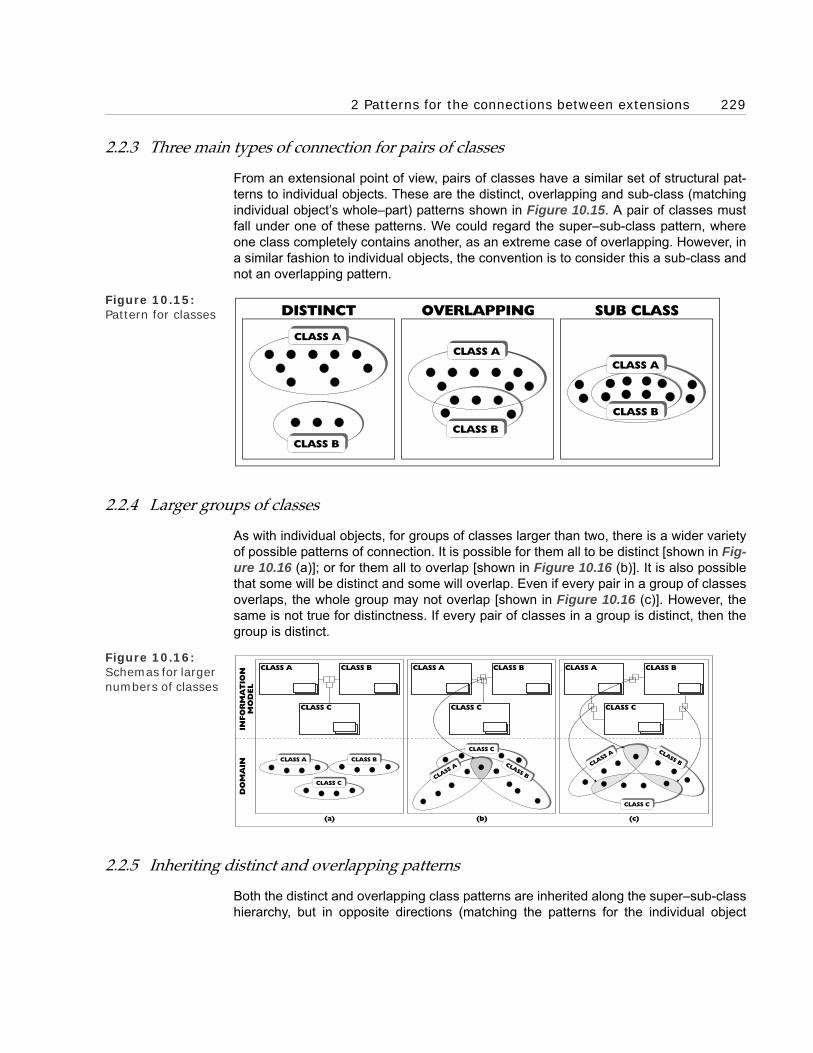
2 Patterns for the connections between extensions 229
2.2.3 Three main types of connection for pairs of classes
From an extensional point of view, pairs of classes have a similar set of structural pat-terns to individual objects. These are the distinct, overlapping and sub-class (matchingindividual object’s whole–part) patterns shown in Figure 10.15. A pair of classes mustfall under one of these patterns. We could regard the super–sub-class pattern, whereone class completely contains another, as an extreme case of overlapping. However, ina similar fashion to individual objects, the convention is to consider this a sub-class andnot an overlapping pattern.
Figure 10.15: Pattern for classes
2.2.4 Larger groups of classes
As with individual objects, for groups of classes larger than two, there is a wider varietyof possible patterns of connection. It is possible for them all to be distinct [shown in Fig-ure 10.16 (a)]; or for them all to overlap [shown in Figure 10.16 (b)]. It is also possiblethat some will be distinct and some will overlap. Even if every pair in a group of classesoverlaps, the whole group may not overlap [shown in Figure 10.16 (c)]. However, thesame is not true for distinctness. If every pair of classes in a group is distinct, then thegroup is distinct.
Figure 10.16: Schemas for larger numbers of classes
2.2.5 Inheriting distinct and overlapping patterns
Both the distinct and overlapping class patterns are inherited along the super–sub-classhierarchy, but in opposite directions (matching the patterns for the individual object
CLASS B
CLASS A
CLASS B
CLASS A
CLASS B
CLASS A
OVERLAPPING SUB CLASSDISTINCT
CLASS C
CLASS BCLASS A
CLASS C
CLASS BCLASS A
INFO
RM
AT
ION
MO
DEL
DO
MA
IN
CLASS A CLASS A CLASS ACLASS B CLASS B CLASS B
CLASS C CLASS C CLASS C
CLASS A CLASS B
CLASS C
(a) (b) (c)

230 Chapter 10 Constructing Signs for Business Objects’ Patterns
level’s inheritance along the whole–part hierarchy). The distinct pattern is inheriteddown the hierarchy. For example, the classes, birds and bees, are distinct and so theirsub-classes, robins and bumble bees, inherit that distinctness. But, as Figure 10.17illustrates, their super-classes flying animals and insects do not, thus proving distinct-ness is not inherited upwards.
Figure 10.17: Inheriting distinct-ness
Overlapping is inherited up the hierarchy. For example, as illustrated in Figure 10.18,the classes blondes and Germans overlap and so their super-classes, haired peopleand Europeans do as well. However their sub-classes, French blondes and Bavarians,are distinct proving that overlapping is not inherited down the hierarchy.
Figure 10.18: Inheriting overlap-ping
As with the individual level connections, this inheritance has implications for how wemodel. We push the distinct connections as far up the super–sub-class hierarchy as faras they will go and the overlapping connections as far down the hierarchy as they willgo. This compacts and increases the functionality of the model.
FLYINGANIMALS
INSECTS
INSECT
BIRDS
BIRD
BEES
BEE
ROBINS
ROBIN
BUMBLE BEES
BUMBLEBEE
inherited
HAIREDPEOPLE
FRENCHBLONDES
EUROPEANS
EURO-PEAN
BLONDES
BLONDE
GERMANS
GERMAN
BAVARIANS
BAVARIAN
inherited

2 Patterns for the connections between extensions 231
2.2.6 Known and unknown distinct and overlapping patterns
We often do not know all the members of a class. So we cannot always say whether agroup of classes is distinct or overlapping and sign this in the model. This lack of infor-mation is not necessarily a problem. We only need to know the relevant distinct or over-lapping patterns. Working out every pattern, relevant or otherwise, would be a waste oftime.
However, when we want to model a group of classes as overlapping, it helps to know atleast one common (overlapped) member. There is, in principle, nothing wrong with sign-ing them as overlapping when we do not know a common member. However, this is nota good policy. Finding a common member is a sure way of confirming that the classesdo indeed overlap. Even if we are reasonably sure that they do, it makes sense—as asafety check—to follow a policy of confirming our intuitions. We can do this simply andeffectively by finding a common member. Figure 10.19 illustrates this process of confir-mation. If we cannot find a common member, this should make us suspect that theclasses do not, in fact, overlap.
Figure 10.19: Constructing con-firmation of over-lapping
Things are not so easy for distinct patterns. No matter how many distinct instances twoclass signs may have, this does not prove that their classes are distinct. There may bean unknown object that is a member of both classes. So a group of classes cannot belogically proven to be distinct in the same way as they can be proven to be overlapping.This means we need to exercise caution before signing classes as distinct in the model.
2.2.7 The distinct and overlapping class pattern objects
The strong reference principle requires that, as we have signed distinct and overlappingclass patterns, the signs refer to objects. These are constructed in the same way astheir individual object cousins. They are the classes of the distinct (or overlapping)classes. We can illustrate this with the distinct birds and bees classes from Figure10.13. Its distinct sign refers to the class {birds, bees}, which has the birds and beesclasses as its only members. Furthermore, this class is a member of the distinct class.This is shown in Figure 10.20, which also shows an example of the pattern for the con-struction of the overlapping class.
STEP ONE STEP TWO
BLONDESBLONDES GERMANSGERMANS
HELGAHELGA ADOLFADOLF SVENSVEN
Sign Classes asOverlapping
Sign a CommonMember
refe
rs t
o
refe
rs t
o
refe
rs t
o
refe
rs t
o
refe
rs t
o
refe
rs t
o
BLONDESBLONDES GERMANSGERMANS

232 Chapter 10 Constructing Signs for Business Objects’ Patterns
Figure 10.20: Class examples of overlapping and distinct pattern objects
Figure 10.21: Incompletely par-titioned classes
2.2.8 Partitioning patterns for distinct classes
Like individual objects, where a distinct pattern is often part of a larger individual parti-tion pattern, distinct class patterns are often part of a larger class partition pattern. Atype of partitioning class pattern has been a natural way of seeing since well before theemergence of the substance paradigm and its secondary substance hierarchy. Forexample, when we think of the class humans, we almost instinctively start partitioning it,maybe by gender. Then, even though it contravenes the substance paradigm’s singleclassification restriction, some of us also start thinking of alternative ways of partitioning,for example into adults and children. In the class partition pattern, the partitioning classis divided into distinct partitioned sub-classes. As shown in Figure 10.22, the notation is
GERMANSBLONDES
REAL WORLD
OVERLAPPING PATTERN OBJECT
OBJECT SCHEMA
OVERLAPPINGPATTERNOBJECT
su
perfl
ou
s s
ign
s
sign foroverlapping
classobject
refers to
refers to
OVERLAPPINGBLONDES/GERMANSOBJECT
DISTINCTPATTERN OBJECT
GERMANS BEES
BLONDES BIRDS
OVERLAPPING DISTINCT
CHILDREN
CHILD
HUMANS
HUMAN
ADULT
ADULTSMALEHUMANS
FEMALEHUMANS
CHILDREN
CHILD
HUMANS
HUMAN
ADULT
ADULTS
CompositeSuper-SubPartition
Sign
SuperfluousDistinct
SignsMALEHUMANS
FEMALEHUMANS

2 Patterns for the connections between extensions 233
similar to the individual object partition sign—with the component super–sub-class signreplacing the whole–part sign.
Often, the partition pattern does not partition a class completely, partitioning only someof its members into distinct classes. This is a partial or incomplete partition and is signedby adding an incomplete partition component sign to the composite partition sign. Asshown in Figure 10.21, this is a small flat rectangle that is put between the super–sub-class sign and the partition box.
Figure 10.22: Partitioned classes
Figure 10.23: Partition inher-itance
MEN
MAN
MEN
MAN
WOMEN
WOMAN
WOMEN
WOMAN
CHILDREN
CHILD
COMPLETEPARTITION
INCOMPLETEPARTITION
HUMANS
HUMAN
HUMANS
HUMANCompositeIncompletePartitionSign
IncompletePartition
ComponentSign
MALEHUMANS
MALEHUMANS
FEMALEHUMANS
FEMALEHUMANS
ANIMALS
ANIMAL
HUMANS
HUMAN
inheritedpartition

234 Chapter 10 Constructing Signs for Business Objects’ Patterns
2.2.8.1 Partition pattern inheritance
As the example in Figure 10.23 shows, partition patterns (like distinct patterns) areinherited down the super–sub-class hierarchy. The partition into distinct male andfemale animals classes is inherited down the super–sub-class hierarchy to the distinctmale and female humans classes partition. (You will notice that the inherited partition isthe more general male/female partition from Figure 10.22 rather than the human spe-cific men/women partition from Figure 10.21.)
As with individual level partitions, this has implications for how we model class parti-tions. It is useful to push them as far up the super–sub-class hierarchy as they will go,increasing the number of classes that can inherit the pattern. This compacts andincreases the functionality of the model.
2.2.9 Intersection patterns for overlapping classes
Sometimes we want to work with a class constructed from objects that are members ofthe overlap of a group of classes. This is an intersection pattern, which goes one stepfurther than the overlapping pattern and constructs the class of the overlapped mem-bers. The intersection pattern only applies to overlapping classes, it cannot apply to theother two types of class patterns: distinct and sub-class. Distinct classes have no mem-bers in common and so have no use for the intersection pattern. Sub-classes have alltheir members in common with their super-class, and so the intersection pattern wouldnot produce a new class.
We can see how the intersection pattern works with an example. Assume we are target-ing a group of companies for a sales campaign and we are going to select the groupfrom a comprehensive list. The list identifies whether companies are large and whethertheir headquarters are in the north or south of the country. If we target large companiesin the north (in other words, the class of companies whose members belong to both thelarge companies class and the northern companies class) then we need the intersectionpattern shown in Figure 10.24. This illustrates the intersection sign, which is anenhanced version of the overlap sign.
Figure 10.24: Intersected classes
SOUTHERNCOMPANIES
COMPANIES
COMPANY
INFO
RM
AT
ION
MO
DEL
DO
MA
IN
CompositeIntersectionSign
IntersectionComponent
SignLARGE
COMPANIES
refe
rs t
o
LARGECOMPANIES
NORTHERNCOMPANIES
NOTHERNCOMPANIES
refe
rs t
o
LARGENORTHERNCOMPANIES
LARGENORTHERNCOMPANIES

2 Patterns for the connections between extensions 235
The example in Figure 10.24 also confirms that only overlapping classes can be inter-sected. It is pointless intersecting the classes northern companies and southern compa-nies because they are distinct (as they are part of a partition). So we know in advancethat the intersecting class would be empty. The intersected classes in the intersectionpattern must be overlapping so that the intersecting class has members.
The intersecting class, large northern companies, is logically dependant on the inter-sected classes, large companies and northern companies. The logical dependency isshown by a black semi-circle sign at the end of the intersection sign (seen in Figure10.24). The class is derived by the logical dependency. This is shown by the derivedsign, a small grey triangle in the bottom left corner of the class sign. Again this is visiblein Figure 10.24. This derived component sign becomes an integral part of the compositesign for the class. It needs to be because the class sign can appear in other schemaswithout the intersection sign and so the logical dependency sign. Then the derived signreminds us of the logical dependency.
2.2.10 Fusion patterns for overlapping classes
Sometimes every member of a group of overlapping classes has an interesting charac-teristic and this is captured by a class that pools all the members of the group ofclasses. For example, at some future date it may be decided to make the citizens ofFrance and Germany citizens of a new Western Alliance state. The class Western Alli-ance citizens is the pooling of the members of the classes French citizens and Germancitizens. This pattern is called a fusion and is modelled using a fusion sign (shown inFigure 10.25). You will notice that the classes French citizens and German citizensoverlap; it is possible to have dual citizenship. If they did not (the classes were distinct),this would be a partition pattern. The fused class, Western Alliance citizens, is logicallydependant on the classes French citizens and German citizens. This is shown in thesame way as for intersected classes, with a logical dependency and a derived sign.
Figure 10.25: Fusion sign WESTERN
ALLIANCECITIZENS
INFO
RM
AT
ION
MO
DEL
DO
MA
IN
CompositeFusionSign
FusionComponent
Sign
WESTERNALLIANCECITIZENS
GERMANCITIZENS
GERMANCITIZENS
refe
rs t
o
FRENCHCITIZENS
FRENCHCITIZENS
refe
rs t
o

236 Chapter 10 Constructing Signs for Business Objects’ Patterns
2.2.11 A close-knit family of extension patterns
This examination of the patterns of connections between extensions has revealed aclose-knit family of patterns. We have seen how patterns at the individual object levelrepeat themselves at the class level. How patterns are inherited up and down thesuper–sub-class and whole–part hierarchies. How we can and should generalise theconnections along their inheritance hierarchies to compact and increase the functional-ity of the model. The examples have given us a feel for how these patterns work withone another. As we get more experience of business object modelling, they will becomesecond nature.
3 State hierarchy patterns
In Chapter 7, we examined how object semantics explained substance’s states asphysical bodies that are temporal parts of other physical bodies. Here, we look at thebasic object syntax for states. We look at the sign for a state and how to model the fol-lowing state patterns:
• State–sub-class hierarchy patterns,
• State–sub-state hierarchy patterns,
• Distinct state patterns,
• Partitioned state patterns, and
• Overlapping state patterns.
These are all spatio-temporal patterns. In the next section, we look at temporal (timeordered) patterns.
Figure 10.26: Temporal–whole–part or ‘state–of’ sign
3.1 The state–of sign
A state is a physical body that is a temporal part of another physical body. This linkbetween the state and the physical body is a particular type of whole–part tuple. Con-sider the lepidopter example from Chapter 7 (illustrated in Figure 7.2), where caterpillar#2 is a state of lepidopter #1. As Figure 10.26 shows, the state–of tuple is a couple<lepidopter #1, caterpillar #2> belonging to the temporal–whole–part tuples class. (Thisis the states tuples class; all states are, by definition, temporal parts of physical bodies.)
CATERPILLAR#2
LEPIDOPTER#1
State-Of orTemporal-
Whole-PartComponent Sign
Composite State-Ofor Temporal-Whole-Part TupleSign
superflous signs
TEMPORAL-WHOLE-PART
TUPLESWHOLE-PART
TUPLES

3 State hierarchy patterns 237
The temporal–whole–part tuples class is, in turn, a sub-class of the whole–part tuplesclass.
As the couple belongs (distantly) to the whole–part class, we sign it with a whole–partsign. To reflect the fact that caterpillar #2 is a temporal part (state) of lepidopter #1, thecomposite state–of sign has a state-of or temporal component sign. In Figure 10.26,the whole–part and temporal–whole–part tuples classes are drawn. However, these arenormally left out of the schemas because they are superfluous, implied by the state–ofor temporal–whole–part sign.
Figure 10.27: State–sub-state hierarchy pattern
Figure 10.28: State–sub-class hierarchy pattern
3.2 State–sub-state hierarchy patterns
We saw in Chapter 7 that states can have states and this leads to a state–sub-statehierarchy pattern. In the example illustrated in Figures 7.6 and 7.7, caterpillars hadearly and late stage sub-states, where a substate is defined as a temporal part of a tem-poral part. So, as shown in Figure 10.27, the pattern is signed using the state–of sign.
LATESTAGECATER-PILLARS
EARLYSTAGECATER-PILLARS
CATER-PILLARS
LEPI-DOPTER
LEPIDOPTERA
GREENCATER-PILLARS
REDCATER-PILLARS
LEPIDOPTERA
LEPI-DOPTER
CATER-PILLARS
T
TEMPORAL-WHOLE-PARTTUPLES
State-Sub-Class
Tuple
su
perflu
ou
ssig
ns

238 Chapter 10 Constructing Signs for Business Objects’ Patterns
You should notice that this pattern is at the member level, with the state tuples signsconnecting the classes’ member signs.
3.3 State–sub-class hierarchy patterns
Chapter 7 also shows us that states are collected into state classes that can havestate–sub-classes. This state–sub-class pattern is just a super–sub-class pattern,where the classes are state classes. Figure 10.28 shows this using the example illus-trated in Figures 7.8 and 7.9, where the caterpillars (state) class has red and green(state) sub-classes.
Figure 10.29: Distinct and parti-tioned states
3.4 Other extension-based state patterns
States, as physical bodies, fall into the same extension-based patterns as other physicalbodies. For instance, they have the distinct, overlapping and partitioned patterns weexamined in the beginning of this chapter. We illustrate this using the lepidopter exam-ple again. Its states are distinct and also completely partition the lepidopter object. Fig-ure 10.29 models these two patterns. You can see that the partition is modelledconnecting the classes’ members icons, this is because it operates at the member level.
Figure 10.30: IOverlapping states
CATERPILLARS
CATER-PILLAR
PUPAE
PUPA
BUTTERFLIES
BUTTER-FLY
DISTINCT
PARTITIONED
CATERPILLARS
CATER-PILLAR
LEPIDOPTERA
LEPI-DOPTER
PUPAE
PUPA
BUTTERFLIES
BUTTER-FLY
LEPIDOPTER#1
INFECTEDLEPIDOPTER
STATE #7
CATERPILLARSTATE #2

4 Time ordered temporal patterns 239
In Figure 10.30, we have used the overlapping caterpillar and infected lepidopter statesfrom Figures 8.10 and 8.11 to illustrate how we sign an overlapping state.
4 Time ordered temporal patterns
In Chapter 8, we examined how object semantics explains changes using these twotypes of object:
• States, and
• Events.
We now look at the object syntax for their time ordered temporal patterns.
4.1 State changes
In object semantics, states are objects and often ordered in time. This ordering can takea number of patterns; we only look at this sample here:
• Simple state ‘change’ patterns,
• Sequence of states pattern, and
• Alternating states pattern.
We then investigate how the state life history of an object is constructed from a states’time ordering patterns.
4.1.1 A simple state ‘change’ pattern
The simplest state change involves a ‘change’ from one state to another—for instance,a change from an ill state into a well state. The states are ordered in time – one after theother. To describe this pattern, we construct a tuple of the two states and sign its orderwith a component time ordering arrow sign (shown in Figure 10.31).
Figure 10.31: Sign for time ordering
4.1.2 A time sequence of states pattern
Often the states of an object fall into a time sequence pattern. We can describe this pat-tern at an individual object level or generalise it to a class level—as in the chairman andlepidopter examples below.
Composite TimeOrdering Sign
Time Ordering ArrowComponent Sign
ILL STATE#11
WELL STATE#12

240 Chapter 10 Constructing Signs for Business Objects’ Patterns
4.1.2.1 Individual object level sequence
The chairman thought experiment from Chapter 8 (illustrated in Figure 8.18) provides agood example of a time sequence pattern of individual states. Each new resignationand appointment leads to a new chairman state. If we extend the pattern in the thoughtexperiment we get a sequence, over time, of chairman states—all states of the chair-man object. In this case, the sequence of states has a temporal gap. This is modelledwith the time ‘gap’ ordering arrow component sign shown in Figure 10.32.
Figure 10.32: Individual object level sequence of states
4.1.2.2 Class level sequence
The ubiquitous lepidopter provides us with an example of a class level sequence pat-tern. Caterpillars develop into pupae that develop into butterflies. It is the members ofthe classes that develop, not the classes themselves, so the ordering sign is linked tothe class members’ signs (shown in Figure 10.33), not the class signs.
Figure 10.33: Class level sequence of states
Figure 10.34: Alternating state patterns
Composite Time GapOrdering Sign
Time Gap OrderingArrow Component Sign
MS BROWNCHAIRMANSTATE #210
MR SMITHCHAIRMANSTATE #64
MR JONESCHAIRMANSTATE #68
LEPIDOPTERA
LEPI-DOPTER
PUPAE
PUPA
T
CompositeNext StateTuples ClassSign
CATER-PILLARS
BUTTER-FLIES
ILL STATES
ILLSTATE
HEALTHSTATES
WELL STATES
WELLSTATE
PERSONS
PERSON
ILLSTATE #11
ILLSTATE #13
WELLSTATE #12
WELLSTATE #14

4 Time ordered temporal patterns 241
4.1.3 Alternating state patterns
States also fall into an alternating pattern, as shown in the well and ill states example inChapter 8 (Figure 8.17). We model this using the sign for time ordering (shown in Fig-ure 10.34). You should notice that, in this case, the model shows both the individualobject and the class level ordering.
Figure 10.35: Three individual lepidopter state life histories
Figure 10.36: A class level lepi-doptera state life history
4.1.4 An object’s state life history
These signs for states' time orderings allow us to tell an individual object’s state life his-tory (or indeed, a class of objects’ state life histories). Consider the lepidoptera exampleagain. To determine its state life history we first need to find all the possible patterns forits individual states. Figure 10.35 provides a simplified version of these in the form ofstate life histories for three individual lepidoptera—each one dying at a different stage of
CATERPILLAR#201
CATERPILLAR#202
PUPA#203
CATERPILLAR#2
PUPA#3
BUTTERFLY#4
BeginningIcon
EndingIcon
LEPIDOPTERA
BUTTERFLIES
CATERPILLARS
CATER-PILLAR
&metamor-phoses
&metamor-phoses
&dies
&dies
LEP
IDO
PT
ER
IS B
OR
N
PUPAE
PUPA
LEPIDOPTERDIES
PUPAMETAMORPHOSES
BUTTERFLYMETAMORPHOSES

242 Chapter 10 Constructing Signs for Business Objects’ Patterns
development. Notice the beginning and ending signs. These are, as you can see, basedon the space-time map icons.
We generalise these individual level patterns into a class level history; the result is Fig-ure 10.36. Notice that as the state life histories are of the individual states of the physi-cal object, the time ordering pattern is between the members and not the classes. Thisis a very simple example. Normally, an object would have a number of different statepartitions, across which states would overlap (illustrated in Figures 8.10 and 8.11).
People familiar with traditional modelling may recognise this as object syntax’s versionof the entity paradigm’s life history diagrams. Getting a picture of something’s life historyis an extremely useful part of business modelling. However, the entity life history has towork within the confines of the entity paradigm, which typically constrains it to a tree-likestructure. Using the more powerful and sophisticated object semantics enables us toconstruct a much more accurate, and so useful, picture of a life history.
4.2 Event cause and effect time orderings
As well as a life history perspective on objects, object syntax offers a cause and effectperspective centred on events. In Chapter 8 we discussed how Aristotle analysedunderstanding into the following four types of cause:
• efficient cause,
• material cause,
• formal cause, and
• final cause.
We now look at how these are modelled with time ordering signs. We do this by exam-ple. We model, using object syntax, the ‘sculptor carving a statue’ example illustrated inFigure 8.26. The result is Figure 10.37. We use a new sign (the pre-condition sign) forthe efficient and material causes because the causes are not ordered before or after theevent, but around it. The efficient and material causes are differentiated because thematerial cause has a temporal–whole–part connection with the formal cause.
Figure 10.37: Object syntax’s event perspective
The life history and event perspectives complement one another. The life history fits thestates into a pattern. The event perspective then explains that pattern by mapping what‘causes’ the events that change the states.
BLOCK OFMARBLE
#102
SCULPTOR#101
STATUE#103
STATUESALE EVENT
#105
CARVINGEVENT#104
Pre-ConditionTupleCompositeSign
MATERIALCAUSE
EFFICIENTCAUSE
FORMALCAUSE
FINAL CAUSE

5 Cardinality patterns for tuples classes 243
4.3 Time ordering tuple objects
We have looked at various time ordering (and pre-condition) signs. We now examine, indeference to the strong reference principle, the objects that these signs refer to. Theyare tuples that belong to the appropriate pattern’s tuples class. At the individual level,they are couple objects as indicated by the two place links to the diamond tuple compo-nent sign. These are members of one or another of the time ordering or pre-conditionpattern’s tuples classes (illustrated in Figure 10.38).
Figure 10.38: Time ordering and pre-condition tuples classes
5 Cardinality patterns for tuples classes
We now move from time ordering tuples to a particular aspect of tuples classes. Welook at a group of useful modelling patterns—cardinalities. Traditional information mod-elling uses cardinality patterns for its relational attributes and we re-engineer a versionof the patterns here. A few differences arise because the tuples class and the occupiedclass places are objects in their own right in object semantics. This is a change from tra-ditional modelling, where cardinalities are implicit parts of relational attributes.
In many cases, it is useful to describe the cardinality patterns of a tuples class, but thisnotation does not insist on it. A number of notations are used for describing cardinalityin traditional information modelling; most of which can be adapted to object semantics. Iprefer to use the simple one described below, but it does not really matter which one isused. I suggest that you use the notation you feel most comfortable with, thoughremember it will probably need some amendments to cope with object semantics.
TUPLES
TIMEORDERING
TUPLES
TEMPORALGAP
TUPLES
TEMPORALLYCONTINUOUS
TUPLES
PRE-CONDITION
TUPLES

244 Chapter 10 Constructing Signs for Business Objects’ Patterns
5.1 Types of cardinality pattern
In the last chapter, we looked at the signs for tuples classes and their occupied classplaces. These occupied class places are the basis for the cardinality patterns. Cardinal-ity is a pattern that, in object syntax, applies to occupied class place objects. When acardinality pattern is signed, both an upper and a lower bound are specified. There aretwo levels for the lower bound—optional or one. There are also two levels for the upperbound—one or multiple. These upper and lower bound levels can be combined in fourways to produce four different cardinality patterns for the occupied class place:
• Optional-to-one pattern,
• One-to-one pattern,
• Optional-to-multiple pattern, and
• One-to-multiple pattern.
We now look at each of these in more detail.
5.1.1 Optional-to-one cardinality pattern
Consider Figure 10.39, which models the person-born-in-Britain tuples class. What isthe cardinality pattern of the class place occupied by the class persons? I have foundthat it is important when determining cardinality to confirm one’s intuitions with specificinstances. I go through this confirmation process step by step in this example.
Prince Philip and Queen Elizabeth are both members of the class persons. Prince Philipis a person and was not born in Britain. So it must be optional for a person to be born inBritain. Or, in object-speak—it must be optional for members of the class persons tooccupy the person place in a couple that is a member of the person-born-in-Britaintuples class. So the lower bound for the occupied class place is zero. This is signed in asimilar way to traditional modelling with an ‘0’ on the line between the occupied classplace and the tuples class sign.
Figure 10.39: Optional-to-one cardinality pattern
Queen Elizabeth is a person and was born in Britain. So a person can be born in Britain(a member of the class persons can occupy the person place in a couple that is a mem-ber of the person-born-in-Britain tuples class). It is safe to assume that a person cannot
BRITAIN
QUEENELIZABETH
BRITAINPRINCEPHILIP
QUEENELIZABETH
'Optional'Lower Bound Sign
'One' UpperBound Sign
PERSON-BORN-IN-BRITAIN
TUPLES
INFO
RM
-A
TIO
NM
OD
EL
DO
MA
IN
refe
rs t
o
PERSON-BORN-IN-BRITAIN TUPLES
refe
rs t
o
PERSONS
PERSONS
refe
rs t
o

5 Cardinality patterns for tuples classes 245
be born more than once, in Britain or anywhere else. So the maximum number of timesa person can appear in the person place of a person-born-in-Britain couple is once. Thismeans the upper bound for the occupied class place is one, which is noted by a ‘1’ signon the class place link. By convention we draw the upper bound sign closer to the tuplesclass sign than the lower bound sign. Both these upper and lower bound signs areshown in Figure 10.39.
5.1.2 One-to-one cardinality pattern
If we now model the son–father tuples class with its place classes son and father thenwe get the schema shown in Figure 10.40. A son always has one and only one biologi-cal father; so, every son appears once and only once in the son place of a father–soncouple. This means the upper and lower bounds are both one. So two ‘1’ signs are putby the occupied class place sign, next to the tuples class sign.
Figure 10.40: One-to-one cardi-nality pattern
Figure 10.41: Figure 10.41 Optional- and one-to-multiple cardi-nality patterns
PRINCEWILLIAM
PRINCECHARLES
INFO
RM
-A
TIO
NM
OD
EL
DO
MA
IN
SONS SON-FATHERTUPLES
FATHERS
refe
rs t
o
refe
rs t
o
refe
rs t
o
FATHERSSONS
'One' UpperBound Sign
'One' LowerBound Sign SON-FATHER
TUPLES
JOHN
ANNE
SUE SUE PROJECT#1
SUE PROJECT#2
JOHN PROJECT#2
PROJECT#1
PROJECT#2
INFO
RM
-A
TIO
NM
OD
EL
DO
MA
IN
EMPLOYEES EMPLOYEE-WORKING-ON-PROJECT TUPLES
PROJECTS
refe
rs t
o
refe
rs t
o
refe
rs t
o
PROJECTSEMPLOYEES 'Multiple'Upper BoundSigns
'Optional' LowerBound Sign
'One' LowerBound Sign
EMPLOYEE-WORKING-ON-PROJECT
TUPLES

246 Chapter 10 Constructing Signs for Business Objects’ Patterns
5.1.3 Optional-to-multiple and one-to-multiple cardinality patterns
Now consider the model in Figure 10.41, this shows the employee–project tuples classoriginally illustrated in Figures 3.23 and 3.24. An employee will sometimes work on anumber of projects. This means the upper bound for the occupied class place must begreater than one. For this, we use the multiple sign. As you can see, it looks like acrow’s foot. Some employees, such as secretarial staff, will never work on a project. Sothe occupied class place has a lower bound of zero. We use the same ‘0’ sign that weused in Figure 10.40 for this. All projects have one or more employees working on them.So the lower bound of the occupied class place link is one and the upper bound is mul-tiple. These optional-to-multiple and one-to-multiple cardinalities are signed in Figure10.41.
5.1.4 Cardinality pattern signs
These examples cover the only four possible signs for the cardinality of an occupiedclass place. A full list is given in Figure 10.42. If we are going to sign the cardinality ofan occupied class place then we will use one of them. Remember, however, that unlikesome traditional modelling notations, each occupied place of a tuples class can begiven a cardinality pattern. So a tuples class can have as many cardinality patterns as ithas occupied class places.
Figure 10.42: The four compos-ite cardinality pat-tern signs
5.2 Cardinality patterns as objects
Cardinality signs, like the distinct and overlapping signs, refer to class objects. But,which class objects? If we analyse the model carefully we can see the members of thecardinality classes—occupied class place objects.
5.2.1 Occupied class places as objects
We looked at the signs for occupied class places in the last chapter (see Figures 9.25and 9.26). We now work out what these signs refer to. We start with the signs for indi-vidual tuples and work up to the occupied class place signs.
Optional
Optional-To-One
Optional-to-Multiple
One-To-One
One-To-Multiple
Multiple
Composite Cardinality Signs
Component Cardinality Signs
CLASS
MEMBER
CLASS
MEMBER
OneCLASS
MEMBER

5 Cardinality patterns for tuples classes 247
The sign for individual tuples, such as <Prince Charles, Prince William>, is a black dia-mond. This component has a number of lines, called (tuple) place component signsjoining the diamond to the signs for the objects that make up the tuple. For example, inFigure 10.43, a component place sign joins the black diamond tuple sign to the PrinceCharles sign.
Figure 10.43: What occupied class places signs refer to
The tuples class signs have a component that looks similar. This is the (tuples) classplace sign. Like the place component sign, it is a line. Unlike it, the line does not have tojoin the tuples class sign to another sign. For example, the class place sign on the rightof the father-child tuples class in Figure 10.43 is not joined to anything. The class placesign can join the tuples class sign to another sign—as shown by the class place signjoining the fathers class sign to the father-child tuples class in Figure 10.43. When thishappens, the class place is said to be occupied and a black diamond (the tuple sign) isadded to the line.
What object does this occupied class place sign refer to? Despite the similarity of thesigns, it cannot reflect a simple construction relationship as the tuple’s place sign does.The connection between the father-child tuples and fathers classes is not one of a tupleconstructed from an object. Instead, it is a tuple, <father-child tuples, fathers> (illus-trated in Figure 10.43). That is why the occupied class place component sign is a blackdiamond, the sign for a tuple. In general, occupied class place signs refer to a couplewith the format <tuples class, place class>.
5.2.2 Cardinality classes with occupied class places as members
These occupied class places are the members of cardinality classes (shown in Figure10.44). For example, the one-to-one cardinality sign refers to the one-to-one bound car-dinalities tuples class. This has as members all occupied class places with a one-to-onecardinality, including the one shown in the figure.
FATHERS
PRINCECHARLES
refe
rs t
o
PRINCECHARLES
PRINCEWILLIAM
Father-Child TuplesOccupied Class Place
INFO
RM
AT
ION
MO
DEL
DO
MA
IN
FATHER-CHILDTUPLES
FATHERSFATHER-CHILD
TUPLES

248 Chapter 10 Constructing Signs for Business Objects’ Patterns
Figure 10.44: Underlying cardi-nality model
The figure also illustrates how, once the composite cardinalities are seen as classes,they can be generalised into their elements. The one-to-one cardinality class can begeneralised as a sub-class of the ‘one lower bound cardinalities’ and the ‘one upperbound cardinalities’ tuples classes. We can also see quite clearly how much easier it isto use the cardinality signs than the more long-winded couple and tuples class–membersigns.
5.3 Inheriting cardinality patterns
There are constraint patterns for the inheritance of cardinality patterns up and down thesuper–sub-class hierarchy. They are easy to work out; so try doing it for yourself.
6 A pattern for compacting classes
So far, in this chapter, we have looked at how object syntax helps us model objects.Now, we turn our attention to a pattern that helps us generalise classes and so compactthe model. This is the pattern of tuples classes defining their place classes.
Once we identify the pattern, we generalise the place classes up the super–sub-classhierarchy. We can then eliminate the original, less general, place classes. This com-pacts the model without compromising its information content. This is a good illustrationof one way in which compacting works and how we handle it within object syntax. Weshall re-use this compacting pattern in the worked examples in Part F.
6.1 Constructing an example of the pattern
To illustrate the compacting, we need an example of the pattern. We get one by con-structing a derived place class from a tuples class. Step one, shown in Figure 10.45, istaking the father–child tuples class. At this stage, it has no occupied class places. Steptwo is identifying in each of the member tuples, the object that occupies the father
CLASS
MEMBER
LOWERBOUND
CARDINALITIES
CLASS
MEMBER
su
perfl
ou
s s
ign
s
CLASS
MEMBER
UPPERBOUND
CARDINALITIES
'OPTIONAL TO ONE'BOUND
CARDINALITIES
'ONE TO MULTIPLE'BOUND
CARDINALITIES
'OPTIONAL'LOWER BOUNDCARDINALITIES
'ONE'LOWER BOUNDCARDINALITIES
'ONE TO ONE'BOUND
CARDINALITIES
'ONE'UPPER BOUNDCARDINALITIES
'OPTIONAL TO MULTIPLE'BOUND
CARDINALITIES
'MULTIPLE'UPPER BOUNDCARDINALITIES

6 A pattern for compacting classes 249
place. Step three is collecting all these objects into a class. This gives us a fathers classthat occupies one of the father–child tuples class places.
Figure 10.45: Constructing the logically depend-ent place class fathers
The class fathers is defined as those persons who have a father–child tuple linkingthem to a child—so it is logically dependent on the father-child tuples class. This makesit derived. This is modelled in the usual way; with logical dependency and derived signs(shown in Figure 10.45).
We will spot this pattern frequently if we keep asking whether there is a logical depend-ency between a tuples class and its place classes. Until now, we have tended toassume that they are logically independent. In this father–child tuples case, and manyother cases, if we had asked ourselves the question, we would have realised that thereis a logical dependency.
Figure 10.46: Making a derived place class redun-dant
6.2 Using the pattern to compact the model
We now have an example of the pattern of tuples classes defining place classes. So wecan illustrate the compacting. We do this in the three steps shown in Figure 10.46. Inthe first step, we generalise the fathers class (the occupied class place) up the super–
PRINCECHARLES
PRINCECHARLES
PRINCEHARRY
PRINCEHARRY
PRINCECHARLES
PRINCECHARLES
PRINCEPHILIP
PRINCEPHILIP
PRINCECHARLES
PRINCEHARRY
PRINCECHARLES
PRINCEHARRY
PRINCECHARLES
PRINCEWILLIAM
PRINCECHARLES
PRINCEWILLIAM
PRINCEPHILIP
PRINCECHARLES
PRINCEPHILIP
PRINCECHARLES
FATHERS
FATHER
FATHER-SONTUPLES
FATHER-SONTUPLES
ST
EP
ON
EST
EP
TW
OST
EP
TH
REE
FATHER-SON TUPLES
FATHER-SON TUPLES
FATHER
PRINCECHARLES
PRINCEHARRY
PRINCECHARLES
PRINCEWILLIAM
PRINCEPHILIP
PRINCECHARLES
FATHER-SONTUPLESFATHER-SON TUPLES
FATHERS
FATHER
STEP ONE STEP TWO STEP THREE
PERSONS
PERSONsi a f at her of
FATHERS
FATHER
PERSONS
PERSON
si a f at her of
PERSONS
PERSONsi a f at her of

250 Chapter 10 Constructing Signs for Business Objects’ Patterns
sub-class hierarchy to the persons class. In the second step, we generalise the ‘is afather of’ occupied class place from the father class to the persons class. At this stage,the fathers class no longer has a role to play; so, we classify it as redundant. The greyderived component sign in step one becomes a black redundant component sign. In thethird and final step, we eliminate the now redundant fathers class from the model.
Often, when we are growing a business model, we construct classes that are logicallydependent on tuples classes. These normally serve a purpose during the early stages.But, in most cases, they are redundant and so do not need to be implemented. As themodel matures, we compact it by eliminating the redundant classes.
In this example of the compacting process, we eliminated the fathers class. However, itis sometimes useful to keep a record of redundant classes. Then, we do not eliminatethe class but leave it in the model flagged as redundant. It then occupies a kind of limbo,kept in the model for reference purposes only.
7 Where we are
Compacting the model is an important part of business modelling, and generalising aclass place’s link up the super–sub-class hierarchy is a useful pattern for compacting.The other patterns we looked at are also useful when business modelling. We will findourselves (re-)using most of them. As well as constructing object models of useful pat-terns, this chapter has helped us develop a clear idea of how the object notation cap-tures patterns of business objects, an essential part of good business object modelling.
This is the end of the first half of the book, the part that concentrates on helping youunderstand what business objects are. In the next half of the book, Part F, we useworked examples to demonstrate an approach that uses business objects to re-engi-neer the entity formats of existing systems.

BOROBORO
Part FApplying Business Objects
Chapter 11 BORO: An Approach to Applying Business Objects
Chapter 12 Re-Engineering Country’s Entity Format
Chapter 13 Generalising Country’s Re-Used Patterns
Chapter 14 Re-Engineering Our Conceptual Patterns for Country
Chapter 15 Re-Engineering Region
Chapter 16 Re-Engineering Bank Address
Chapter 17 Re-Engineering Time
Chapter 18 Starting a Re-Engineering Project


BOROBORO
Chapter 11BORO: An Approach to Applying
Business Objects
1 Introduction
2 The BORO approach
3 The worked examples
4 A systematic approach to re-engineering
5 A framework for the model
6 Generalisation and compacting
7 What’s next

254 Chapter 11 BORO: An Approach to Applying Business Objects
1 Introduction
In Parts A to E we developed an understanding of the object paradigm and businessobject modelling. We now know what a business object is and how to model it. Here, inPart F, we develop a feel for how to apply business objects to re-engineering entity-based computer systems. We do this by working through several examples using thesystematic BORO method. In this introductory chapter to Part F, we take an overview ofthe BORO method and the content of the worked examples.
2 The BORO approach
The BORO method is designed to re-engineer the business paradigms embedded inexisting computer application systems—ones that are used for such tasks as account-ing or foreign exchange trading. It is here that we start to see the actual benefits of re-engineering.
The previous parts of the book have been, in some ways, a preparation for this. Whenwe re-engineered the entity paradigm into the object paradigm, we gained a clearunderstanding, at a general level, of:
• What the object paradigm is,
• What kind of business objects the world contains, and
• How to describe these in a model.
These are worthy achievements, but by themselves they do not actually deliver anybusiness benefit. We harvest the benefits when we re-engineer our entity-based com-puter application systems.
Our re-engineering of the entity paradigm in the previous parts of the book involvedchallenging fundamental assumptions—the more fundamental the better. Now that wehave established the object paradigm, we start working within its fundamental assump-tions. In this part of the book, we re-engineer the entity business paradigms embeddedin computer systems into object business paradigms (illustrated in Figure 11.1). Wetransform their entity-formats into an object model, using the object paradigm as a foun-dation, rather than the subject of the re-engineering. This re-engineering, by its verynature, is less fundamental and more structured. This has certain advantages. Becausewe are working within a framework, we can guarantee a practical result. This takes theuncertainty out of re-engineering.
Figure 11.1:Re-engineering entity business paradigms
EntityParadigm
ObjectParadigm
ObjectParadigm
#2 EntityBusinessParadigm
#1 EntityBusinessParadigm
#2 EntityBusinessParadigm
#1 EntityBusinessParadigm
#2 ObjectBusinessParadigm
#1 ObjectBusinessParadigm
STEP ONE STEP TWO
SHIFTING TO THEOBJECT PARADIGM
SHIFTING THEBUSINESS PARADIGMS

3 The worked examples 255
Using entity-based computer systems as the starting point for our re-engineering ena-bles us to define a systematic method for re-engineering (the BORO method). Thismakes the re-engineering both effective and efficient. This is very different from discov-ering a fundamental shift, such as the shift to the object paradigm, which involves thekind of inspiration that cannot be planned in advance. With the BORO method, the re-engineering of the entity business paradigms can be planned and executed with a rea-sonable amount of precision. This makes it a viable commercial approach.
3 The worked examples
The easiest and best way to learn the approach is by working through examples. That iswhat we do in the following chapters.
3.1 Picking an element of an existing computer system
In each example, we pick a small element of an existing computer system; typically:
• An entity type,
And, its associated;
• Attribute types,
• Entities, and
• Attributes.
We use these as the starting point for the re-engineering process. For each of them, wework through a series of steps that transmutes their primitive entity formats into a pow-erful and sophisticated object model.
The worked examples serve two purposes:
• First, they help us to understand what re-engineering a business paradigm involves and how the BORO method works.
• Second, they provide us with basic object models, which we can re-use again and again in subsequent re-engineerings.
Because the examples include fundamental business patterns (ones that are used in awide range of businesses), the basic object models are likely to be reusable in most re-engineerings.
3.2 The worked examples’ business patterns
The worked examples are organised into groups based on two types of business pat-tern:
• Spatial patterns, and
• Temporal patterns,

256 Chapter 11 BORO: An Approach to Applying Business Objects
The first group—spatial patterns—is based on three simple entity formats that are foundin many business computer systems:
• Country,
• Region, and
• Address.
We re-engineer these into a comprehensive object model of our spatial patterns. In theprocess, we also re-engineer a general object model for naming patterns.
The second group—temporal patterns—is based on two simple entity formats:
• Bank holiday, and
• Weekend.
We re-engineer these into a general object model of our temporal patterns.
The early examples are designed to help you become familiar with the systematicre-engineering method by carefully taking you through each step in the process. Webegin with a simple example—country—whose re-engineering is straightforward. Thisprovides a comfortable atmosphere in which to start establishing the basic principles ofthe method.
The later examples, building on the established principles, are designed to help youunderstand what is happening in the re-engineering and to develop a feel for how enti-ties are transformed into objects. You will learn how to construct simple general objectsthat, through re-use, compact the object model. And, you will begin to appreciate howaccurate your analysis needs to be within the object paradigm.
3.3 Entity formats based on working computer systems
All the entity formats in the examples have come from working computer systems. Ihave changed some details, for reasons such as confidentiality and ease of understand-ing. They are common formats that could have come from any number of systems. Inthe examples, we assume that they come from a single working computer system (thisis not too far from the truth).
4 A systematic approach to re-engineering
A systematic approach to re-engineering entity formats is made possible by the founda-tion work done on the re-engineering of the entity paradigm into the object paradigm.Over the years, I have refined the systematic approach into a more formal method ini-tially called REV-ENG. This is a nick-name that a modelling team gave to an early ver-sion of the method; it is a contraction of REVerse ENGineering. (When we first started,we thought that what we were doing was reverse engineering. It was only later that werealised we were re-engineering; hence, the name.) Subsequently we have named themethod the BORO (Business Object Reference Ontology) Methodology. The methodsimplifies the re-engineering process by formalising the approach into the step-by-stepsystem illustrated in the worked examples.

4 A systematic approach to re-engineering 257
4.1 Re-engineering data
The method focuses on re-engineering data—in particular the entity formats in an exist-ing legacy system. In my experience the data in most systems contains enough of theimportant patterns to enable us to construct the general patterns needed for a compre-hensive business model. (Remember, as we discussed in Chapter 2, that the data con-tains patterns for both business bodies and events.)
Process is deliberately ignored by the method. In the early days, we attempted to re-engineer both data and process. However, we soon found that it is practically impossi-ble to effectively re-engineer process into a business model. The problem is that pro-cess has a language-like linear structure. (That is why we talk about programminglanguages in contrast to database management systems.) Like everyday language (andunlike paper tables and computer data), these linear constraints so seriously distort pro-cess’s view of the business that it cannot be re-engineered systematically. This hasnever caused us a problem. We just simplified the re-engineering by ignoring process.This was no loss; the more explicitly structured data contained more than enough of theobject patterns we needed (including event patterns).
4.2 Stages in the method
The worked examples make more sense if we first look briefly at an outline of themethod. The method divides the re-engineering into two main stages:
• Re-engineering the entity format of the existing entity system, and
• Re-engineering our conceptual patterns for the entity format.
These are illustrated in Figure 11.2.
Figure 11.2: Two stages of re-engineering
4.2.1 Re-engineering the entity format of the existing entity system
The elements of the entity format are re-engineered one by one. Each re-engineeringstarts with a sign in the entity format; from it an entity in the ‘real world’ is identified. Thisentity is then re-engineered into an object and a sign constructed for the object in themodel. This process is illustrated in Figure 11.3.
Re-EngineeringThe Existing
System'sEntity-Format
Re-EngineeringOur Conceptual
Patterns For The Entity Format
Entity-Format

258 Chapter 11 BORO: An Approach to Applying Business Objects
Figure 11.3: Re-engineering the existing sys-tem’s entity for-mat
4.2.1.1 Rules for ordering the elements of the re-engineering
I have found that it is worth following two simple rules when choosing the order in whichto re-engineer the various elements of the entity formats. This makes the whole processof re-engineering much more straightforward.
The first rule is:
Re-engineer the individual entity and entity type signs before their associated individual attribute and attribute type signs.
This is only common sense. We obviously need to work on the entity sign, before wecan move onto its dependant attribute signs.
The second rule—for individual entities and entity types—is:
Re-engineer a couple of individual entity signs and use the patterns to re-engi-neer their entity type sign.
This again is common sense. It is much easier to establish the patterns with more tangi-ble individual entities than with ‘abstract’ entity types. This is sometimes called workingby example.
The second rule only needs a change of name to apply to attributes. After the change, itreads:
Re-engineer a couple of individual attribute signs and use the patterns to re-engineer their attribute type sign.
4.2.2 Re-engineering our conceptual patterns for the entity format
In the second stage of the process we re-engineer our conceptual patterns (in otherwords, the patterns our brain uses) for the entities in the entity format. This follows simi-lar steps to the first stage, with the addition of one initial step. We:
• Find a relevant conceptual pattern,
ENTITY OBJECT
ENTITYSYSTEM
OBJECTMODEL
ENTITYDOMAIN
ENTITY PARADIGM OBJECT PARADIGM
OBJECTDOMAIN
ENTITY FORMAT RE-ENGINEERING PROCESS
IDENTIFYENTITY
RE-ENGINEERINTO ANOBJECT
CONSTRUCTOBJECT
SIGN
EntityFormat
Sign

4 A systematic approach to re-engineering 259
• Identify the entity (entities) the conceptual pattern refers to,
• Re-engineer it (them) into objects, and
• Then construct signs for the objects in the model.
These steps are illustrated in Figure 11.4. The reason we need the extra first step offinding a relevant conceptual pattern is that—unlike the entity formats in the existingcomputer systems, these are not formally listed. It involves some effort and, in somecases, ingenuity to find relevant ones.
Figure 11.4: Re-engineering our conceptual patterns
4.3 Following the systematic method
In the worked examples, these two stages (and the steps within them) occur repeatedly.However, once we have firmly established the steps in the process, we focus on thenature of the re-engineering. This means that, in later examples, we do not workthrough each step in detail.
This should not be seen as a licence to miss out steps when you re-engineer. It istempting to do so, but you should resist. Go through every step in the process, espe-cially the first few times you re-engineer. Even someone who is experienced can easilytake a wrong turning. Relying on intuition or a gut feeling, particularly at the start, is asure recipe for slipping back into the old (entity) way of seeing and almost bound to leadyou astray. Following the full process helps keep you on the straight and narrow.
Furthermore, and perhaps as important, when the model is being reviewed, yourdetailed workings will make it much easier for the reviewer to see any wrong turningsyou may have taken. With the workings revealed, the re-engineering will not look like aseries of magic rabbits appearing from nowhere out of top hats.
CONCEPTUAL PATTERN RE-ENGINEERING PROCESS
ENTITY OBJECT
OUR CONCEPTUALSYSTEM
ENTITY PARADIGM OBJECT PARADIGM
OBJECTMODEL
ENTITYDOMAIN
OBJECTDOMAIN
IDENTIFYENTITY
IDENTIFYCONCEPTUAL
PATTERN
RE-ENGINEERINTO ANOBJECT
CONSTRUCTOBJECT
SIGN

260 Chapter 11 BORO: An Approach to Applying Business Objects
5 A framework for the model
In the worked examples, you will see that the objects have been allocated to one ofthese three broad levels:
• Framework level,
• Application level, and
• Operational level.
I have found that this not only makes the model easier to understand but helps in thesystem building process.
5.1 The framework level
The framework level contains the object meta-model. I have found it helps to have thisexplicitly described in the model. So, rather than start each project with a blank sheet ofpaper, I start with a framework meta-model.
In the object schemas, I identify the framework level with a background shading. Figure11.5 has a sample. Any model object within the shading is a framework object.
Figure 11.5: An example of framework level shading
5.2 Other levels in the model
There are two non-framework levels:
• The application level, and
• The operational level.
I call those model objects that will be built during the system development, applicationlevel objects. I call those that are typically set up during live operation by the users ofthe finished system, operational objects.
I use a similar shading method of identification to differentiate these two levels ofobjects. I shade the background of the operational level objects; so, by default, theapplication level objects have no background shading. Figure shows an example of thedifferent shadings. In it the class transactions is in an area with no shading signifying it
CLASSES
TRANS-ACTIONS
FRAMEWORKLEVEL

5 A framework for the model 261
is application level; whereas Transaction #123 is in an area of light shading signifyingthat it is an operational level. As you can see in the figure, the framework shading isdarker than the operational shading.
Figure 11.6: An example of operational level shading
I find it useful to start modelling with individual objects, particular examples of the moregeneral classes. These are more tangible and help me (and others) to see the underly-ing patterns more clearly. These individual objects are often operational level, objectsthat the users would set up. Consequently, I usually end up with quite a number of oper-ational objects in my working model. When I tidy up the model for the next stage of sys-tem building, I purge them because they are not needed.
5.3 Assuming that all classes are application level objects
Working in the entity paradigm, it is easy to assume that the application-operational andtype-individual distinctions are the same or similar. In other words, that all entity typesare application level and all individual entities are operational level. This assumption iswrong.
Some people carry this mistaken assumption across into object modelling. Theyassume that all classes are application level and all individual objects are operationallevel. This places an unnecessary restriction on their modelling. We can show this withexamples of classes that are at the operational level and individual objects at the appli-cation level.
Consider the car types class modelled in Figures 6.8 and 6.9. This has a memberclass, Minis. If we assume all classes are application level, we would classify the Minisclass as application level. However, if someone was building a general package for carmanufacturers, it would make no sense for them to construct in the system ‘individual’car types, such as Minis, that vary from manufacturer to manufacturer. They would leteach manufacturer set up their own. So Minis, despite being a class, is an operationalobject.
CLASSES
TRANSACTIONS
TRANSACTION#123
FRAMEWORKLEVEL
APPLICATIONLEVEL
OPERATIONALLEVEL

262 Chapter 11 BORO: An Approach to Applying Business Objects
Consider a general Bank of England reporting system for banks. We would expect thisto contain information about the Bank of England as standard. Because it is an individ-ual object, not a class, we might be tempted to allocate it to the operational level of ourbusiness model. Yet, it is not something that the users at individual banks would beexpected to set up. So, despite being an individual object, it is an application levelobject. This and the last example are modelled in Figure 11.7.
Figure 11.7: Examples of appli-cation and opera-tional level objects
5.4 Levels as objects
In the object paradigm, with its strong reference principle, the level shadings are signsreferring to objects—level objects. The framework level object is the meta-class of allthe framework objects. Each level object is the meta-class of all objects in that level.These meta-classes are modelled in Figure 11.8, which also shows the individual appli-cation and overlapping operational objects illustrated in Figure 11.7—though withouttheir connections.
Figure 11.8: Level objects
5.5 Expanding the framework level—the general lexicon
I find it useful to expand the framework level into a ‘starter pack’ for future re-engineer-ing projects. I call this a general lexicon.
OPERATIONALLEVEL
MINIS
MY CARoperationallevel class
application levelindividual object
APPLICATIONLEVEL
REGULATORYAUTHORITY BANK OF
ENGLAND
CARTYPES
OBJECTS
FRAMEWORKOBJECTS
APPLICATIONOBJECTS
OPERATIONALOBJECTS
META-MODEL
INFORMATION MODEL
CLASSES INDIVIDUALOBJECTS
MINIS
MY CAR
REGULATORYAUTHORITY BANK OF
ENGLAND
CARS

5 A framework for the model 263
5.5.1 What is a general lexicon?
In everyday language, a lexicon is a store of words or concepts. Dictionaries can beseen as, and in some cases, have been called lexicons. As far as a business objectmodelling is concerned, the general lexicon is a store of general re-usable modelobjects.
I have found that I can manage generalising and identifying similar objects across pro-jects more effectively, if I use a general lexicon. This stores the model objects that havefruitful patterns, ones that are re-used in most models. I classify all these as frameworklevel. So, for all practical purposes, the general lexicon is the framework level.
Sometimes I have found, and you will find, it useful to create specialist lexicons for spe-cialist areas of the business. For instance, if you were to work on a number of account-ing systems, you might construct an accounting lexicon. These would contain models ofthe accounting objects that you found were re-used in most of the accounting models.
5.5.1.1 General lexicon as a transformation of the Aristotelian categories
The general lexicon can usefully be seen as the object paradigm’s transformation of theAristotelian categories (discussed in Chapter 4 and illustrated in Figure 4.14). Theobject meta-model embedded in the framework level is the transformed version of Aris-totle’s framework of categories—substance and types of attribute (quality, quantity,etc.). The rest of the general lexicon is the transformed version of the lower level Aristo-telian categories. It records the same types of things, such as the humans class being asub-class of the more general animals class.
5.5.2 Constructing a general lexicon.
An essential precursor to the construction of a useful general lexicon is identifyingmodel objects that will be re-used. If, over a sufficiently large number of models, themodel of a particular object (or group of objects) is re-used frequently, then it is a likelycandidate for the general lexicon. The naming pattern that appears in all of the firstgroup of worked examples is a good example.
With experience, modellers find that they can judge whether model objects are candi-dates for the general lexicon. There is a useful rule of thumb that helps them make thatdecision. It is the more general a model object, the more likely it is to be re-used; theless general, the less likely it is to be re-used. Here, we measure generality in terms ofhow high up either the class–member or super–sub-class hierarchies the object is. Theclass objects is the limiting case; it is at the top of both hierarchies. As we move downthe hierarchies from objects, we get closer and closer to the border of the general lexi-con (framework level) and the application level (illustrated in Figure 11.9).

264 Chapter 11 BORO: An Approach to Applying Business Objects
Figure 11.9: The general lexi-con border
The exact location of the general lexicon border is a matter of opinion. Different peoplesometimes have slightly different views. In the end, it does not matter exactly where theborder is, so long as the majority of really re-usable model objects are inside it, ready forre-use.
When we decide a model object belongs to the general lexicon, implementing this deci-sion is trivial; we classify it as framework level. Because the general lexicon is tied intothe framework level, whenever we classify a model object as framework level, it auto-matically belongs to the general lexicon.
6 Generalisation and compacting
A key objective of business object modelling is generalising objects. This is what deliv-ers compacting and its associated benefits.
6.1 Spotting that objects share the same patterns
An important element in generalisation is spotting that objects share the same patterns.The schemas are a useful tool for this. They describe the pattern of relations betweenobjects. This is what Frege called the sense element of meaning—distinguishing it fromthe reference element (we looked at Frege’s description of meaning in the Figure 5 ).The object schemas (and so the business model) map Fregean sense patterns. Map-ping these sense patterns creates an environment that encourages generalisation. Theobject schemas play a key role. They can make the sense patterns explicit in a way thatmakes similar patterns easier to spot.
The way in which the schema is drawn influences how it is understood. In well drawnschemas, similar patterns have similar shapes, making them easier to spot. However, abadly drawn schema can make two similar patterns look dissimilar. So, it is worth
OBJECTS
GENERAL LEXICON(FRAMEWORK)LEVEL
APPLICATIONLEVEL
OPERATIONLEVEL
GeneralLexicon Border
HIERARCHY

6 Generalisation and compacting 265
spending some time drawing an object schema properly. I find that I sometimes gothrough five or more drafts before I arrive at something I am happy with. This is worthdoing because it encourages substantial generalisation, and so substantial compacting.
6.2 Compacting metrics
I find that I can get a rough idea on how successful the re-engineering is by monitoringthe scale of generalisation and compacting.
6.2.1 Population, re-use and generalisation metrics
I usually measure the compacting directly with population metrics that compare thenumber of items in the existing entity system with the number in the object model. I alsomeasure the actual amount of re-use and generalisation that has occurred in the re-engineering of the business model. By comparing the two sets of metrics, I can see thecorrelation between generalisation, re-use and compacting.
6.2.2 Model levels
I normally divide the metrics into levels. I do this for both the entity system and objectmodels' metrics. The entity system’s metrics are divided into the following two levels:
• Type, and
• Individual.
The object model’s metrics are divided into the following three levels:
• Framework,
• Application, and
• Operational.
The framework level objects are separated so that they can be excluded from the over-all metrics. We exclude them because they are not constructed during the re-engineer-ing. They are part of the framework model rather than the model for the particular re-engineering.
The application and operational level objects are included in the overall metrics, but adistinction is made between the two because only the application level objects arepassed onto the systems analysis stage. By contrast, operational objects are eventuallypurged from the business model. These are just examples of the types of objects thatthe user will construct after the system has gone live. So these two levels can be usedto separate the impact on compacting of generalisation during development—the appli-cation level—from that during operation—the operational level.
Even though we formally purge the operational objects from the business model, weoften use them during the later stages of system building. For example we might usethem for illustrative examples during the systems analysis and also as the basis for thetest data used in system testing.

266 Chapter 11 BORO: An Approach to Applying Business Objects
7 What’s next
Enough of this ‘abstract’ discussion of re-engineering. It is time to look at the workedexamples, including their metrics. We start in the next chapter with the first group—spa-tial patterns—and its first entity format—country.

BOROBORO
Chapter 12Re-Engineering Country’s Entity
Format
1 Introduction
2 The systematic re-engineering process
3 The context for re-engineering
4 Re-engineering country entity type sign
5 Re-engineering attribute type signs
6 Basic elements of the re-engineering completed

268 Chapter 12 Re-Engineering Country’s Entity Format
1 Introduction
We now start on the re-engineering of country—the first of three spatial patterns (listedin Figure 12.1). In this worked example, we start growing our object model for spatialpatterns by re-engineering the country entity format. We will extend the model in thenext two worked examples by re-engineering the region and address entity formats. Thefinal model then forms a very basic building block that we can re-use repeatedly whenwe re-engineer (and build) business systems.
Figure 12.1:First of three examples of spa-tial patterns
We start by re-engineering the spatial patterns embedded in the country’s entities andentity type. This is a simple and straightforward task. It will appear mostly as just goodcommon sense—careful, accurate, and maybe a little pedantic—but still commonsense. This establishes the patterns of re-engineering, which we can then (re-)use laterwithout too much explanation.
We then re-engineer the country format’s two attribute types, both names, to reveal acommon name pattern. Most entities have name attributes and so, in a re-engineeringof any size, the name pattern is bound to crop up many times. This makes it is a veryuseful pattern.
The name pattern had to be stretched and twisted to fit into the entity paradigm’s frame-work. So the example provides us with a good illustration of how the process of re-engi-neering unwinds distorted entity formats, and the kind of unfamiliar objects this canproduce. As we shall see, this involves paying particular attention to the accuracy of theanalysis.
Once we have found the new name pattern, we need to absorb it into our way of seeing.Unfortunately, most of us have the current distorted entity name pattern deeply embed-ded in the way we see. So, even though the undistorted object name pattern is clearerand simpler, it can appear odd and awkward at first sight. But once we learn to see withthe new pattern, we appreciate its superiority.
2 The systematic re-engineering process
We follow the systematic re-engineering process, working in two stages as described inthe previous chapter and shown in Figure 12.2. In the first stage, we re-engineer the
COUNTRY REGION ADDRESS
SPATIAL PATTERNSSPATIAL PATTERNS

3 The context for re-engineering 269
existing system’s country entity format into a model that maps business objects. At thesecond stage, we re-engineer our (typically entity-based) conceptual patterns—in otherwords, the ideas in our heads—into business objects and include them in the model.
Figure 12.2: The two stages of re-engineering
In this first example, we build up our understanding of how the re-engineering works, bygoing through it in some detail. This takes up quite a lot of space and so is spread overthree chapters. In the first two chapters, we go through the first stage—entity format re-engineering. In this first chapter, we re-engineer the elements of the country’s entity for-mat. In the second chapter, we generalise the country’s re-used patterns. In the thirdchapter, we go through the second stage—conceptual pattern re-engineering.
3 The context for re-engineering
We now get down to the nitty-gritty of entity format re-engineering. The first step is get-ting a context, finding out what we are going to re-engineer. We know it is the countryentity, but we need to know more than this.
People can understand a lot about what a particular entity format is by looking at exam-ples of its entities and their associated attributes. In this worked example, we use thePartial Country Listing given in Table 12.1. This is the sort of ‘file listing’ a computer sys-tem constructed using the entity paradigm would produce. Here, we are only interested
Re-EngineeringThe Existing
CountryEntity-Format
Re-EngineeringOur Conceptual
Patterns For Country
CountryEntity-Format
Country Name Country Code
Germany DM
Italy IT
Japan JP
Turkey TK
United Kingdom UK
United States US
Table 12.1: Partial Country Listing

270 Chapter 12 Re-Engineering Country’s Entity Format
in the two name attributes shown in the listing; we ignore any other attributes countrymay have. From Table 12.1, we can deduce that the relevant part of the country formatlooks like Table 12.2..
3.1 The re-engineering framework
When we start the re-engineering, we do not have to grow the new model from scratch.We use a framework model or general lexicon as our starting point (see Chapter 11).We do not need the full framework for this example; we only take the partial frameworkshown in the object schema in Figure 12.3, and grow the country object model under-neath.
Figure 12.3: Partial framework object schema
3.2 The systematic approach to re-engineering
The three steps in the systematic approach to re-engineering the country entity (type)—one of the country entity format’s elements—are illustrated in Figure 12.4. Notice theprocess starts with the country entity sign, not the country entity, and ends with a coun-try model object, not the country object. This is because we are re-engineering informa-tion; so we re-engineer from entity signs to object signs. The heart of the re-engineeringprocess is, however, entities, objects and their semantics, not their signs. Before we canconstruct the object sign in the object model, we have to:
• Identify the entity that the entity sign refers to, and
• Re-engineer it into an object (or, in some cases, a number of objects).
Attribute Type #1 Attribute Type #2 Etc.
Country full name Country code -
Table 12.2: Country Entity Format
OBJECTS
OBJECT
EVENTS
EVENT
BODIES
BODY
CLASSES
CLASS
THINGS
THING
TUPLES CLASSES
TUPLES
TUPLES

4 Re-engineering country entity type sign 271
Figure 12.4: First stage – re-engineering the country entity
3.3 Following the ordering rules for re-engineering
We now follow the two simple rules for ordering the re-engineering of entity formats setout in the previous chapter. The first rule applied to country is:
Re-engineer the country individual entity and entity type signs before their associ-ated individual attribute and attribute type signs.
The second rule—for the country entity type—is:
Re-engineer a couple of the country individual entity signs and use the patterns to re-engineer the country entity type sign.
4 Re-engineering country entity type sign
Following the rules, we start with the country entity type sign and select one of its entitysigns from the Partial Country Listing in Table 12.1. It does not matter which one,because they should all exhibit country patterns. We pick the last entry in the table asour first sign—the United States entity sign.
4.1 Re-engineering the first individual entity sign
This table entry is a record of a United States entity sign on our existing computer sys-tem. We have no real problem finding the sign, it is the United States record on theCountry File. We now need to work out what individual entity this sign refers to.
4.1.1 Identifying the United States entity
As Figure 12.4 shows, at this stage we are working within the entity paradigm. In Chap-ter 4 , we looked at how the substance paradigm’s semantics explained what individualentity signs referred to. That they refer to individual entities constructed from an under-
COUNTRYENTITY
COUNTRYOBJECT
ENTITYSYSTEM
OBJECTMODEL
ENTITYDOMAIN
ENTITY PARADIGM OBJECT PARADIGM
OBJECTDOMAIN
COUNTRY ENTITY RE-ENGINEERING PROCESS
IDENTIFYCOUNTRY
ENTITY
RE-ENGINEERINTO COUNTRY
OBJECT
CONSTRUCTCOUNTRY
OBJECT SIGN
CountryEntitySign

272 Chapter 12 Re-Engineering Country’s Entity Format
lying primary substance, to which attributes are attached (illustrated in Figure 4.1). Weapply the explanation to this particular example. The United States individual entity signrefers to the ‘primary substance’ of the country we call the United States. The primarysubstance and its attributes, in some sense, make up the United States. This is showndiagrammatically in Figure 12.5.
Figure 12.5: United States pri-mary substance
4.1.2 Re-engineering the United States object
We now re-engineer the country primary substance into a country object. In the objectparadigm, we see in four-dimensional terms, so we see the United States object asoccupying both space and time. The re-engineering is relatively simple. We take theUnited States current three-dimensional extension—in entity paradigm terms, the posi-tion or place attribute. We then follow the United States’ three-dimensional extensionback and forward in time, filling in a four-dimensional extension. This process is illus-trated in Figure 12.6. The resulting four-dimensional extension is the United Statesobject.
Figure 12.6: Four-dimensional object, the United States
To increase coherence, we need to find a connecting pattern between the United Statesobject and the framework objects (those shown in Figure 12.3). To do this we ask—what type of object is the United States object? The answer is clear; it persists throughtime and so is a body object. This gives us our pattern. There is a class–member pat-
Position
Size
etc.
refers to
UNITEDSTATES
refers to
refers to
refers to
UNITED STATESPRIMARY SUBSTANCE
ENTITY SYSTEMENTITY DOMAIN
Position
SizeUN
ITED
STA
TES
AT
TR
IBU
TES
etc.
TIME
Four-DimensionalUnited States

4 Re-engineering country entity type sign 273
tern linking it to the framework’s bodies class; in other words, it is a member of the bod-ies class. This introduces a second object; the class–member tuple constructed fromthe two objects.
4.1.3 Constructing the United States object sign
We carry out the final step in re-engineering by constructing signs for the two objects.We construct an individual body object sign for the United States object and a class–member sign for the tuple object. The resulting model is shown in the schema in Figure12.7. This also shows how we used a class–member tuple to graft the new UnitedStates object onto the framework’s bodies class.
Figure 12.7: United States object schema
In Figure 12.7 the framework, application and operational levels are signed using theshading convention described in Chapter 11 (and illustrated in Figure ). The UnitedStates sign is in the operational level. This is because the users of the system areexpected to decide what countries to set up on their system, and so whether to set upthe United States. Operational objects, like this one, naturally emerge during the re-engineering. We eventually purge them when we produce an application version of themodel for the system designers to work on.
Figure 12.8: Re-engineering the existing sys-tem’s United States entity sign
UNITEDSTATES
BODIES
BODY
UNITED STATES ENTITY SIGN RE-ENGINEERING PROCESS
IDENTIFYUNITED STATES
ENTITY
RE-ENGINEERINTO UNITED
STATES OBJECT
CONSTRUCTUNITED STATES
OBJECT SIGN
UNITED STATESENTITY SIGN
ENTITYSYSTEM
ENTITY PARADIGM OBJECT PARADIGM
ENTITYDOMAIN
OBJECTDOMAIN
OBJECTMODEL
UNITED STATESSUBSTANCE
UNITED STATESOBJECT
UNITED STATESOBJECT SIGN
UnitedStates UNITED
STATES

274 Chapter 12 Re-Engineering Country’s Entity Format
4.1.4 The re-engineering of the United States entity sign
We have now worked through the three steps of entity format re-engineering. We havere-engineered the United States entity sign into the United States object sign. This isshown in Figure 12.8. In sign terms, this might not look like much of a change, but, insemantic terms, things in the domain have changed dramatically. These differencesemerge in the model as it captures the pattern of connections between objects.
Some people may find the analysis above far too detailed, thinking that we are wastingtime dealing with the obvious. They might think it is clear what the United States is;though I suspect it may not be clear to many of them that it is a four-dimensional object.However, it is important to recognise that we are shifting to a full blown object paradigm.Remember that the whole point of a paradigm shift (particularly one as fundamental asthis) is that it makes us look at things in a new and different way. What we previouslythought clear and obvious now becomes suspect. We have immersed ourselves in theentity paradigm for so many years that we will need to work hard to overcome the habitsand prejudices we have built up. Only careful and systematic analysis of exactly whatthings are, as in this example, will keep us on the straight and narrow.
4.2 Re-engineering the second individual entity sign
Following the rule about re-engineering a couple of entity signs, we pick a second entitysign and re-engineer it. We pick it from the partial listing of countries in Table 12.1. Thistime we pick the United Kingdom sign. We follow the same pattern of re-engineering aswe used for the United States entity sign. Because the pattern is the same, the detailsare not repeated here. We end up constructing a sign for the United Kingdom objectand including it in the object model. This gives us an object schema that looks like Fig-ure 12.9.
Figure 12.9: United Kingdom object schema
Not surprisingly, it has the same pattern as the United States object schema in Figure12.7. We now integrate the two schemas and get Figure 12.10. Because the individualcountries are only two of many, the class–member tuple sign to the partition box is par-tial (shown by the small rectangle).
UNITEDKINGDOM
BODIES
BODY

4 Re-engineering country entity type sign 275
Figure 12.10: Merged United States and United Kingdom object schema
4.3 Re-engineering the entity type sign
We are now ready to re-engineer the country entity type sign. We follow the same threesteps we used for the entity signs.
• We identify the country entity type the sign refers to.
• Then we re-engineer the country entity type into a country object.
• Then we construct a country sign in the object model for the country object.
We looked at what an individual entity sign referred to when we re-engineered theUnited States entity sign earlier in this chapter. It referred to the primary substance towhich attributes attach. We now ask—what does the country entity type sign refer to?
Figure 12.11: Country secondary substance
In Chapter 3, we saw that the entity type sign refers to a secondary substance. Onethat we can see as the sum of primary substances. Using this pattern, the country entitytype sign then refers to country secondary substance (shown in Figure 12.11). We can
UNITEDSTATES
UNITEDKINGDOM
BODIES
BODY
COUNTRYSECONDARYSUBSTANCE
PR
IMA
RY
SU
BSTA
NC
ES
refers to
COUNTRY
ENTITYDOMAIN
ENTITYSYSTEM

276 Chapter 12 Re-Engineering Country’s Entity Format
see this as the sum of the primary substances of countries like the United States andthe United Kingdom.
We now need to re-engineer the entity type—the country secondary substance—into anobject. In Chapter 4 (on the logical paradigm), we looked at a pattern where secondarysubstances evolved into classes. We use this pattern here and transform the countrysecondary substance into the class of countries. Because the individual countries havefour-dimensional extensions, so does the class.
We now work out the pattern of structural interconnections with the existing model. Thecountries class has as members the individual physical body objects: United States andUnited Kingdom. It is a class; so, it is a member of the framework class, classes. Itsmembers are all physical body objects; so, it is a sub-class of the bodies class.
Now that we have re-engineered the class, we construct the countries class sign andthe signs for its patterns of structural connections in the object model. Figure 12.12shows the results. Because we are working in the object paradigm’s notation, the coun-tries class sign (unlike the entity type sign) differentiates between the name sign for theclass—countries—and the name sign for its members—country. Note that the countriesclass is an application, rather than operational, level object—one that we will use tospecify the system.
Figure 12.12: Countries object schema
Figure 12.13 illustrates the overall re-engineering process for the entity type.
We step back and look at both the objects and the object model from outside using thereference diagram in Figure 12.14. There, we can see how the pattern of connectionsbetween the countries class sign and other signs in the object model reflects the patternof connections between the objects.
The re-engineering of the country entity type and its associated entity is now completed.This step-by-step walk through the process should have given you a clear idea of howthe systematic BORO method works.
COUNTRIES
COUNTRY
UNITEDSTATES
UNITEDKINGDOM
BODIES
BODY
CLASSES
CLASS

5 Re-engineering attribute type signs 277
Figure 12.13: Re-engineering the country entity type
Figure 12.14: Countries class reference diagram
5 Re-engineering attribute type signs
We are now ready to start re-engineering the country entity format’s attribute type signs.Both of these are names but, before we start, I warn you again that names work in avery different way in the entity and object paradigms. Some of us are so acclimated tothe successful way they work in the entity paradigm that we are going to need to workhard to get to grips with the new perspective—even though it is simpler.
COUNTRIES
COUNTRY
COUNTRY ENTITY-TYPE SIGN RE-ENGINEERING PROCESS
IDENTIFYCOUNTRY
ENTITY
RE-ENGINEERINTO COUNTRY
OBJECT
CONSTRUCTCOUNTRY
OBJECT SIGN
COUNTRYENTITY-TYPE
SIGN
ENTITYSYSTEM
ENTITY PARADIGM OBJECT PARADIGM
ENTITYDOMAIN
OBJECTDOMAIN
OBJECTMODEL
COUNTRYSUBSTANCE
COUNTRY CLASSOBJECT
COUNTRY CLASSOBJECT SIGN
Country
COUNTRYSECONDARYSUBSTANCE
COUNTRY
OB
JEC
T M
OD
EL
OB
JEC
TS
COUNTRIES
refe
rs t
o
refe
rs t
o
UNITEDSTATES
UNITEDKINGDOM
refe
rs t
o
COUNTRIES
COUNTRY

278 Chapter 12 Re-Engineering Country’s Entity Format
5.1 Re-engineering the country full name attribute type sign
We start the re-engineering with the country full name attribute type sign. The attributeversion of the second rule applies:
Re-engineer a couple of individual attribute signs and use the patterns to Re-engi-neer their attribute type sign.
We need to pick individual attribute signs for our attribute type sign. We start by pickingthe United States entity sign’s country full name attribute sign ‘United States’.
5.2 Re-engineering the first individual attribute sign
We again follow the three steps in our systematic approach. We start with the actualattribute sign itself in the computer system. This is the full name field of the UnitedStates record and contains the character string ‘United States’ (recorded in the first col-umn of the last entry in Table 12.1).
5.2.1 An implicit relational attribute sign
This full name field is an attribute sign and so refers to an attribute, but identifying whichone is not straightforward. Although the attribute sign looks like a non-relational attributesign, it is actually an implicit relational attribute sign related to an implicit United Statesfull name entity sign (shown in Figure 12.15). It is not uncommon to find these implicitsigns when re-engineering. They are the result of trying to use the entity paradigm todescribe patterns that do not fit into its constrained structure. We re-engineer thisimplicit relational attribute sign in two steps. We start by re-engineering the implicit‘United States’ full name entity sign and then re-engineer the relational attribute.
Figure 12.15: Implicit relational attribute
5.2.2 United States full name entity
The ‘United States’ full name entity sign refers to the ‘United States’ full name entity.This is not particularly informative; it is easier to understand what the entity is by work-ing out what object it is re-engineered into. What object can this be? It cannot be a sin-gle character string, such as the string in the full name field on the computer’s UnitedStates record or the string in the last entry of the partial country listing in Table 12.1. Itsomehow refers to both of these, as well as all other ‘United States’ character strings.This gives us our clue—it is the class of these character strings—as shown in Figure12.16.
UNITEDSTATES
UNITEDSTATESFULLNAME
UNITED STATES
FULL NAME

5 Re-engineering attribute type signs 279
Figure 12.16: United States full names class
To tie the class’s reference down, we need to tie down the reference of the members ofthe class—in this case, the individual character strings. We need to see these as four-dimensional objects, persisting through time. The individual character string objects cre-ated by different ‘technologies’ have different characteristics. Characters in the writtenstrings produced by pen and paper technology persist through time together. For exam-ple, the ‘U’ and ‘n’ of ‘United States’ exist at the same time, as shown in Figure 12.17.
Figure 12.17: Example of a par-ticular four-dimen-sional written United States full name
Figure 12.18: Example of a par-ticular four-dimen-sional spoken United States full name
Spoken characters in strings, the product of speech technology, have their charactersspread through time. In this case the ‘U’ exists before the ‘N’, as shown in Figure 12.18.
5.2.3 United States full names class
These four-dimensional objects are the members of the United States full name class.Every time someone says, writes down or, most importantly for us, keys into a computersystem, the character string ‘United States’, and this names the United States; then thecharacter string belongs to the United States full names class. This analysis means thatin the object scheme of things, we read the sentence;
UNITED
STATESUNITEDSTATES
Red
United
States
FULLNAME
UNITEDSTATES
UNITED STATESFULL NAMES
TIME
UNITED STATESUNITED STATES
UNITED STATESUNITED STATES
TIME

280 Chapter 12 Re-Engineering Country’s Entity Format
The full name of the United States is ‘United States’
as
‘United States’ is a member of the United States full names class.
We now follow the same pattern as before and work out the structural connections forthe class object. We have already done some of the analysis; we have worked outsome of its members. Because the object is a class, it is a member of the frameworkclass, classes. We then construct the sign for the object and its patterns in the objectmodel. The result is shown in Figure 12.19.
Figure 12.19: United States full names object schema
5.2.4 Full naming tuples class
We now start re-engineering the second part of the attribute—the implicit relationalattribute sign that points to the ‘United States’ full name entity sign. This refers to the fullnames relational attribute that relates the United States substance to the United Statesfull names entity (shown in Figure 12.15). In Chapter 5 (where we introduced tuples),we looked at the basic re-engineering pattern for relational attributes. It transforms theminto a couple belonging to a tuples class. Applying the pattern to this example, the rela-tional attribute re-engineers into the couple <United States body object, United Statesfull names class> belonging to the country full naming tuples class. This is showngraphically in Figure 12.20.
Figure 12.20: The United States full naming couple
UNITEDSTATES FULLNAMES
CLASSES
CLASS
'UNITEDSTATES'
'UNITED
STATES'
THEUNITED STATESFULL NAMING
COUPLE
UNITED STATESFULL NAMES
UNITED STATES
COUNTRY FULLNAMING TUPLES

5 Re-engineering attribute type signs 281
We look for the tuples class and couple’s structural patterns. The tuples class is a classof couples and so a sub-class of the framework class, tuples. We construct the signs forthe tuples class and couple and its structural patterns and include them in the objectmodel. The resulting object schema looks like Figure 12.21.
Figure 12.21: United States full naming tuples object schema
You will have noticed that the United States full names class is classified as derived.This is shown by the shaded grey triangle at the bottom left of the rectangle. It is definedby the United States full naming couple. This is because a name is only a name if itnames something; without the naming couple it is not a name.
5.2.5 The basic naming pattern
The re-engineering of the attribute sign uncovered the tuples class that links the UnitedStates to its full name class. But it has not fully explained what this object is and so wecannot see the basic naming pattern clearly. We need to dig a bit deeper.
Even though the United States is connected to the full names class, and we call the con-nection a naming pattern, we never actually use it to refer to the United States. What weuse is the naming pattern class’s members; for example, we say ‘United States’ namesthe country the United States. This more particular naming pattern is shown in Figure12.22.
Figure 12.22: United States naming pattern
se man yll uf
UNITEDSTATES FULLNAMES
COUNTRIES
COUNTRY
UNITEDSTATES
fully named by
TUPLES CLASSES
CLASS
BODIES
BODY
COUNTRY FULLNAMING TUPLES
UNITED STATESFULL NAMING COUPLE
refers to
MODEL DOMAIN
A PARTICULARUNITED STATES NAME

282 Chapter 12 Re-Engineering Country’s Entity Format
Every time we use a United States full name (a member of the United States full nameclass), we get the same naming pattern. In object terms, this particular pattern trans-lates into a couple object, with the country the United States and the character string‘United States’ as components. This couple object belongs to the United States fullnaming tuples class (shown in Figure 12.23). This is an example of the objects behindthe basic naming pattern.
Figure 12.23: United States full naming tuples class
Every member of the United States full names class has the naming pattern shown inFigure 12.22. This suggests a new and better way of re-engineering the full name rela-tional attribute. Might it not be re-engineered into the United States full naming tuplesclass, instead of the couple <United States body object, United States full name class>we re-engineered earlier? This offers a much more satisfactory explanation of what isgoing on.
Figure 12.24: United States full naming tuples object schema
We work out the pattern of structural connections, construct the objects and revise theobject model. This gives us the object schema in Figure 12.24. The model shows thatthe link between the United States body and the United States full names class is now atuples class rather than a couple. It is an unusual tuples class in that one of its links is to
AN INDIVIDUALUNITED STATESFULL NAMING
COUPLE
UNITED STATES FULLNAMING TUPLES
'UNITEDSTATES'
COUNTRIES
COUNTRY
UNITEDSTATES
UNITEDSTATES FULLNAMES
TUPLES CLASSES
CLASS
BODIES
BODY
UNITED STATESFULL NAMING TUPLES

5 Re-engineering attribute type signs 283
an individual body object instead of to the more usual class’s member. You will havenoticed that the United States full names class is still classified as derived—shown bythe shaded grey triangle at the bottom left of the rectangle. This time it is defined by theUnited States full naming tuples class.
5.2.6 Exemplar United States full name
The analysis is not yet complete; there is one last bit of investigation we need for thenaming pattern. We need to take a more accurate than usual look at how names refer.This will make us revise a simple commonly held notion—that the signs in a model areclearly separated from the things they refer to in the domain (shown in Figure 12.25).
Figure 12.25: Simple view of object model’s separation from the domain
This is an accurate enough view most of the time; but for the element of the name pat-tern we are looking at now, it is a little too simplistic. Most of us assume that ideas aremental and objects physical; so, assume that ideas and signs are totally separate fromthe objects that they refer to. However, in the object paradigm, signs in the object modelare not necessarily mental. Furthermore (as we saw in Chapter 9 when we constructeda (model)2 model (illustrated in Figures 9.39 and 9.40) signs are as much ‘objects’ asthe objects they refer to in the domain. In this scheme of things, there is, in principle, noabsolute separation between signs and objects. In fact, signs are objects—modelobjects. So there is no reason why one of these model objects cannot be in both theobject model and the domain.
We can see an example of this if we accurately examine the United States full nameattribute again. The attribute is actually an example of a full name. In other words, it isnot only an example of the attribute type but also a sign for it. Mixing entity and objectdomains, we can say the United States full name attribute sign (an element of the exist-ing system) is a member of the United States full name class (an element of thedomain).
This is naming by example—a very simple and effective way of naming. It eliminates theneed to construct the ‘meaningless’ signs normally used in language. Coin-operatedfood dispensers often use a similar system; for instance, the button for dispensing aparticular chocolate bar has one of the bars displayed behind the button. The advan-tage of this way of naming is that there is less chance of misrepresentation. The dis-pensed chocolate bars can easily be compared with the bar on display.
This is the motivation behind the United States full name attribute sign. When a charac-ter string is keyed into the computer system, it can be compared with the sign’s charac-ter string to determine whether it also belongs to the United States full name class.Figure 12.26 illustrates the state of affairs. It also illustrates a new, more sophisticatedview of how the domain and the object model relate. The United States full names class
DOMAIN OBJECT MODEL
OBJECT refers to SIGN
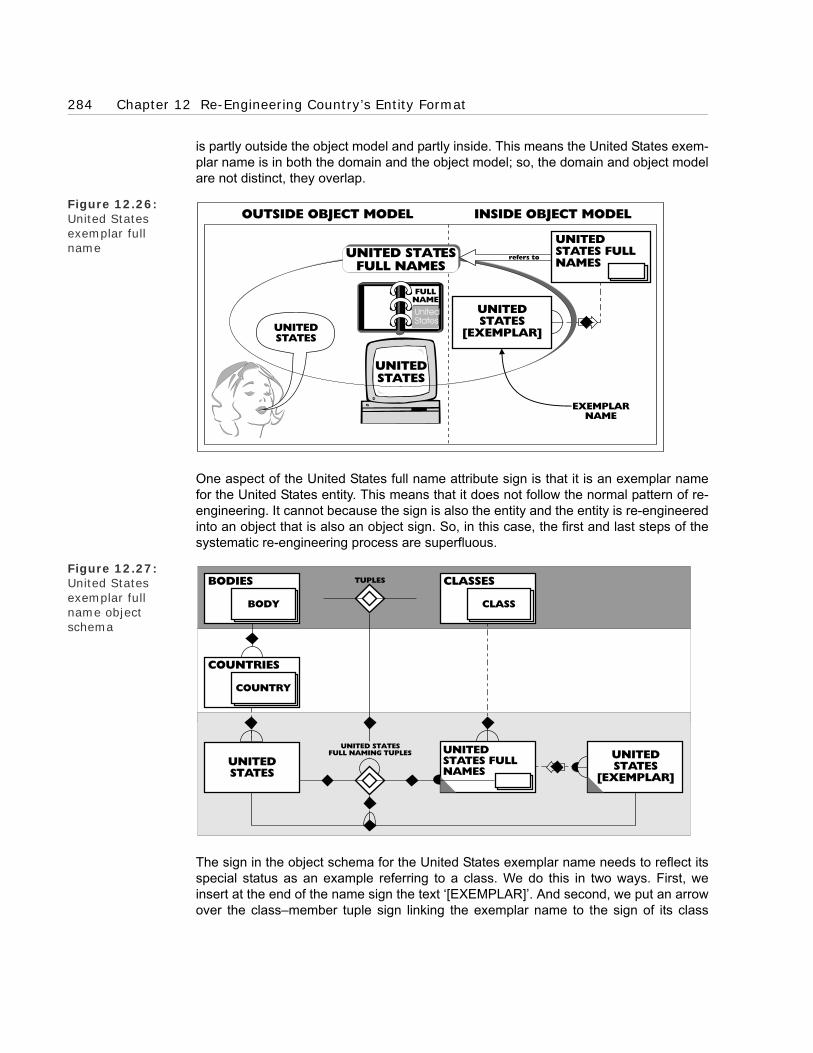
284 Chapter 12 Re-Engineering Country’s Entity Format
is partly outside the object model and partly inside. This means the United States exem-plar name is in both the domain and the object model; so, the domain and object modelare not distinct, they overlap.
Figure 12.26: United States exemplar full name
One aspect of the United States full name attribute sign is that it is an exemplar namefor the United States entity. This means that it does not follow the normal pattern of re-engineering. It cannot because the sign is also the entity and the entity is re-engineeredinto an object that is also an object sign. So, in this case, the first and last steps of thesystematic re-engineering process are superfluous.
Figure 12.27: United States exemplar full name object schema
The sign in the object schema for the United States exemplar name needs to reflect itsspecial status as an example referring to a class. We do this in two ways. First, weinsert at the end of the name sign the text ‘[EXEMPLAR]’. And second, we put an arrowover the class–member tuple sign linking the exemplar name to the sign of its class
EXEMPLARNAME
UNITEDSTATES
Red
United
States
FULLNAME
UNITEDSTATES
[EXEMPLAR]
INSIDE OBJECT MODELOUTSIDE OBJECT MODEL
UNITEDSTATES
UNITED STATESFULL NAMES
refers to
UNITEDSTATES FULLNAMES
UNITEDSTATES
[EXEMPLAR]
COUNTRIES
COUNTRY
UNITEDSTATES
UNITEDSTATES FULLNAMES
TUPLES CLASSES
CLASS
BODIES
BODY
UNITED STATESFULL NAMING TUPLES

5 Re-engineering attribute type signs 285
(shown in the object schema in Figure 12.27). You will have noticed that ‘United States[EXEMPLAR]’ (like United States full name) is classified as derived, defined by itsexemplar class–member tuple. If something occupies the member place of the UnitedStates full name exemplar class–member tuple, it must be an exemplar United Statesfull name.
5.3 Re-engineering the second individual attribute sign
We have only re-engineered one attribute for the country full name attribute type. Fol-lowing the rules, we need to re-engineer a second before we re-engineer the attributetype. We pick ‘United Kingdom’ from the partial listing in Table 12.1. We follow the samere-engineering pattern as we used for the ‘United States’ full name attribute. This givesus the object schema shown in Figure 12.28. Not surprisingly, this has the same patternas the United States object schema in Figure 12.27.
Figure 12.28: United Kingdom full names and full naming tuples object schema
The steps in the re-engineering process are not shown here because they are so similarto the ones we used for the ‘United States’ full name attribute. When modelling for real,it is tempting to miss out these steps and just re-construct the United States objectschemas substituting the United Kingdom. This misses the point of the process, whichis to check that the patterns are the same for both attributes before generalising them tothe attribute type. Working through a similar process is often tedious; but it is necessaryto confirm that the patterns are general across the attributes. I tend to find that the onetime I do not work through a similar pattern, Murphy’s law comes into operation. Thepattern contains important variations that I have to go back later to unearth.
UNITEDKINGDOM
[EXEMPLAR]
COUNTRIES
COUNTRY
UNITEDKINGDOM
UNITEDKINGDOM FULLNAMES
TUPLES CLASSES
CLASS
BODIES
BODY
UNITED KINGDOMFULL NAMING TUPLES

286 Chapter 12 Re-Engineering Country’s Entity Format
5.4 Re-engineering the attribute type sign
We can now re-engineer the country full name attribute type. This follows a similar pat-tern to the individual attribute sign, which was re-engineered into a number of relatedobjects. In other words, the attribute signs’ pattern is reflected at the attribute type level.
As with the full name attributes, we start by following the three steps in our systematicapproach. We take the attribute type sign in the computer system. This is the sum of thefull name fields of all the country records on the computer—including the United Statesfull name field and the United Kingdom full name field.
5.4.1 An implicit relational attribute type sign
As with the attribute signs, the first step of re-engineering this attribute type sign (identi-fying the attribute type the sign refers to) is not straightforward. This is because theattribute type sign is implicitly related (like the attribute signs) to a country full nameentity type sign (shown in Figure 12.29). This is, as before, the result of trying to use theentity paradigm to describe patterns that do not fit into its constrained structure.
Figure 12.29: Implicit relational attribute type
5.4.2 Country full names class
Following the same pattern that we used at the attribute level, we start by re-engineer-ing the implicit country full name entity sign. In the entity world, this refers to a countryfull name entity. We now find out what object it is re-engineered into. The classic re-engi-neering pattern for attribute types (which we looked at in Chapter 5 ) has the attributetype transformed into the class of the objects that the individual attributes were re-engi-neered into. This pattern applies here. The country full name attribute type re-engineersinto the country full names class. This is a class with the United States full names classand the United Kingdom full names class as members.
These members are classes; so, country full names is a class of classes (shown in Fig-ure 12.30). The entity paradigm cannot handle this pattern. It had to be distorted to fitinto the entity framework. It also involves a new way of seeing, one unfamiliar to mostpeople and one that treats the full names classes as objects and collects them into thecountry full names class—a class of classes.
PR
IMA
RY
LEV
EL
SEC
ON
DA
RY
LEV
EL
UNITEDSTATES
UNITEDSTATESFULLNAME
COUNTRYFULLNAME
COUNTRY
FULL NAME
UNITED STATES
FULL NAME

5 Re-engineering attribute type signs 287
Figure 12.30: Country full names class
Figure 12.31: Country full names object schema
We increase coherence by recognising a structural pattern—in this case, a class–mem-ber tuple to the framework class, classes. We can now carry out the third step and con-struct the appropriate signs and include them in the object model, giving us the objectschema in Figure 12.31. The class–member sign to the partition box is partial becausethere are other full names for other countries (for instance, Germany full names).
5.4.3 Country full naming tuples classes
Continuing to follow the attribute level pattern, we now re-engineer the relational attrib-ute type sign (shown in Figure 12.29), which points to the country full name entity typesign. This refers to a country’s full name relational attribute type that relates the countryentity type to the country full name's entity type.
UNITED STATESFULL NAMES
UNITED STATESFULL NAMES
UNITED KINGDOMFULL NAMES
UNITED KINGDOMFULL NAMES
INFO
RM
-A
TIO
NM
OD
EL
OB
JEC
TS
COUNTRY
FULL NAMES
UNITED STATES
UNITED STATES
etc.
UNITED KINGDOM
UNITED KINGDOM
etc.
refe
rs t
o
COUNTRYFULL NAMES
COUNTRYFULL NAMES
CLASSES
CLASS
UNITEDSTATES FULLNAMES
UNITEDKINGDOM FULLNAMES

288 Chapter 12 Re-Engineering Country’s Entity Format
Figure 12.32: Country full nam-ing tuples classes
We apply the classic re-engineering pattern for attribute types from Chapter 5 againand transform the relational attribute type into the class of the objects that the attributeswere re-engineered into. This is the class of all the individual country full naming tuplesclasses, such as the United States full naming tuples (shown in Figure 12.32).
Figure 12.33: Country full nam-ing tuples classes object schema
We identify its structural patterns. It has as members both the United States full namingtuples and the United Kingdom full naming tuples. We construct signs for the objects.This gives us the object schema in Figure 12.33. You may notice that country full nam-ing tuples classes is a class of tuples classes, (in other words, a class of classes) andso not a tuples class (which, by definition, has tuples as its members). This means thatcountry full naming tuples classes is related to both countries and country full names bytuples classes of class places, such as country/full naming tuples. In addition, the coun-try full names class (like its member classes) is classified as derived, defined by countryfull naming tuples classes.
COUNTRY FULLNAMING TUPLES CLASS
UNITED KINGDOMFULL NAMING
TUPLES
UNITED KINGDOMFULL NAMING
TUPLES
UNITEDKINGDOM
UNITED STATESFULL NAMING
TUPLES
UNITED STATESFULL NAMING
TUPLES
UNITEDSTATES
UNITEDSTATES FULLNAMES
COUNTRYFULL NAMES
UNITEDKINGDOM FULLNAMES
TUPLES
COUNTRIES
COUNTRY
CLASSES
CLASS
TUPLES CLASSES
TUPLES
BODIES
BODY
UNITEDSTATES
UNITEDKINGDOM
COUNTRYFULL NAMINGTUPLES CLASSES
UNITED KINGDOMFULL NAMING
TUPLES
UNITED STATESFULL NAMING
TUPLES
COUNTRY/FULL NAMING TUPLES
COUNTRY FULL NAME/FULL NAMING TUPLES
fully named b y
fully named b y
se man yll uf
se man yll uf

5 Re-engineering attribute type signs 289
5.4.4 Exemplar country full names class
We then follow the third and final leg of the attribute level pattern and re-engineer exem-plar country full names. We re-engineer this into the class constructed by collectingtogether the individual exemplar full names—the class of exemplar country full names.We work out its structural patterns and construct the appropriate signs in the objectmodel, giving us the object schema in Figure 12.34. This captures the exemplar patternat the class level.
Figure 12.34: Exemplar country full names object schema
5.5 Re-engineering the country code attribute type sign
We have completed the re-engineering of the country full name attribute type. We nowstart re-engineering the second attribute type, country code. This is a name and usesthe same basic naming pattern as country full names and so its re-engineering followsthe same pattern. In a real exercise, it would be important to follow the pattern throughstep by step, no matter how tedious this felt; otherwise, important variations would bemissed. However, for this worked example there is no need to do it.
The results of the re-engineering are the object schemas shown in Figure 12.35 forcountry codes, Figure 12.36 for country coding tuples classes and Figure 12.37 forexemplar country codes. These follow the patterns for country full names shown in Fig-ures 12.31, 12.33 and 12.34. You will note that in Figure 12.36 the country codes classis classified as derived (it is defined by the country coding tuples classes). Similarly theexemplar country codes, in Figure 12.37, is classified as derived (defined by the coun-try code exemplar member tuples class).
UNITEDSTATES FULLNAMES
UNITEDSTATES
[EXEMPLAR]
CLASSES
CLASS
COUNTRYFULL NAMES
EXEMPLARCOUNTRY FULLNAMES
TUPLES
COUNTRIES
COUNTRY
TUPLES CLASSES
TUPLES
BODIES
BODY
UNITEDSTATES
UNITED STATESFULL NAMING
TUPLES
COUNTRY/FULL NAMING
TUPLESCOUNTRY FULL NAME/FULL NAMING TUPLESCOUNTRY
FULL NAMINGTUPLES CLASSES
COUNTRY FULL NAMEEXEMPLAR MEMBER

290 Chapter 12 Re-Engineering Country’s Entity Format
Figure 12.35: Country codes object schema
Figure 12.36: Country coding tuples classes object schema
5.5.1 Re-engineering the naming pattern
Re-engineering these name attribute types should have given us some idea of the dis-tortions that the entity paradigm is forced to make to some patterns to fit them into itsframework. It should also give some idea of how accurate we need to be to see how tounwind the distortions. Country has taken us from one end of the re-engineering spec-trum to the other. Re-engineering the country entity type was simple and straightfor-ward; whereas, re-engineering its name attribute types was far from straightforward. Itneeded careful analysis to reveal the underlying naming patterns.
UNITEDSTATESCODES
UNITEDKINGDOMCODES
COUNTRYCODES
CLASSES
CLASS
TUPLES
COUNTRYCODES
COUNTRIES
COUNTRY
CLASSES
CLASS
TUPLES CLASSES
TUPLES
BODIES
BODY
UNITEDSTATES
UNITEDKINGDOM
COUNTRYCODING TUPLESCLASSES
UNITEDSTATES CODES
UNITEDKINGDOMCODES
UNITED KINGDOMCODING TUPLES
UNITED STATESCODING TUPLES
coded by
coded by
sedoc
sedoc
COUNTRY/CODING TUPLES
COUNTRY CODE/CODING TUPLES

6 Basic elements of the re-engineering completed 291
Figure 12.37: Exemplar country codes object schema
6 Basic elements of the re-engineering completed
We have now completed the direct re-engineering of the elements of the country entityformat. We have constructed an object model that reflects the re-engineered objects.However, we have not completed the first stage yet. We still need to take advantage ofany opportunities for generalising the objects. We do this in the following chapter.
UNITEDSTATESCODES
CLASSES
CLASS
COUNTRYCODES
EXEMPLARCOUNTRYCODES
TUPLES
COUNTRIES
COUNTRY
TUPLES CLASSES
TUPLES
BODIES
BODY
UNITEDSTATES
UNITED STATESCODINGTUPLES
COUNTRY/CODINGTUPLES
COUNTRY CODE/CODING TUPLES
COUNTRY CODEEXEMPLAR MEMBERCOUNTRY
CODINGTUPLES CLASSES
US[EXEMPLAR]

292 Chapter 12 Re-Engineering Country’s Entity Format

BOROBORO
Chapter 13Generalising Country’s Re-Used
Patterns
1 Introduction
2 Generalising re-used patterns
3 First stage of the re-engineering completed

294 Chapter 13 Generalising Country’s Re-Used Patterns
1 Introduction
In the previous chapter, we re-engineered the elements of the existing system’s entityformat directly into an object model. In this chapter, we complete the first stage of the re-engineering by generalising the patterns re-used in the modelling.
2 Generalising re-used patterns
In the previous chapter, we focused on the direct re-engineering of the entity format intoobjects. We now focus on a less direct form of re-engineering—generalisation. This isessential to any good re-engineering because it leads to the compacting that makes themodel simpler and more powerful.
In practice, the direct re-engineering and generalisation would go on hand in hand, but Ihave kept them separate here because it is easier to examine them on their own.
We now work through how we generalise the example. Even this early on in the re-engi-neering, there are opportunities for generalisation. A good indication of an opportunityfor generalisation is patterns of objects that have been re-used in the modelling. In thisworked example, there are three obvious candidates:1. The re-use of the country full names pattern in the re-engineering of country codes.2. The re-use of the country full naming tuples classes pattern in the re-engineering of
country coding tuples classes.3. The re-use of the exemplar country full names pattern in the re-engineering of
exemplar country codes.
2.1 Generalising country full names and codes
We not only re-used the same pattern in the re-engineering of country full names andcountry codes; the two objects’ connecting patterns are also very similar. This indicates
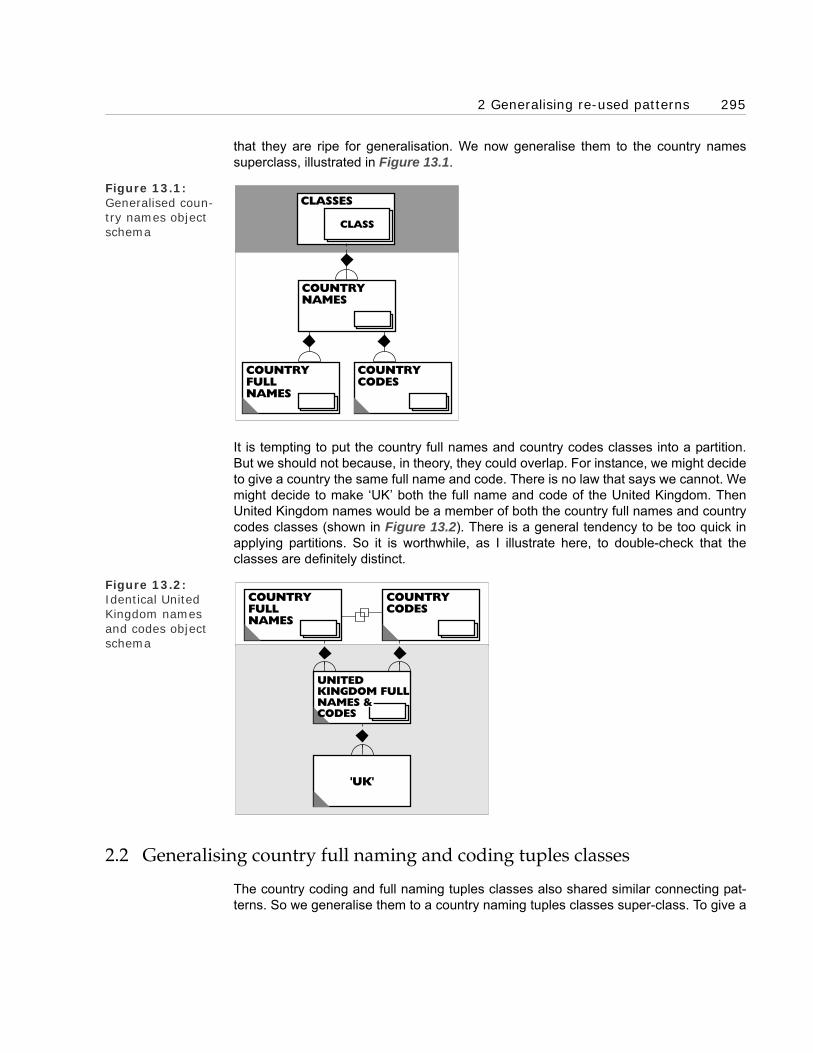
2 Generalising re-used patterns 295
that they are ripe for generalisation. We now generalise them to the country namessuperclass, illustrated in Figure 13.1.
Figure 13.1:Generalised coun-try names object schema
It is tempting to put the country full names and country codes classes into a partition.But we should not because, in theory, they could overlap. For instance, we might decideto give a country the same full name and code. There is no law that says we cannot. Wemight decide to make ‘UK’ both the full name and code of the United Kingdom. ThenUnited Kingdom names would be a member of both the country full names and countrycodes classes (shown in Figure 13.2). There is a general tendency to be too quick inapplying partitions. So it is worthwhile, as I illustrate here, to double-check that theclasses are definitely distinct.
Figure 13.2: Identical United Kingdom names and codes object schema
2.2 Generalising country full naming and coding tuples classes
The country coding and full naming tuples classes also shared similar connecting pat-terns. So we generalise them to a country naming tuples classes super-class. To give a
COUNTRYNAMES
COUNTRYFULLNAMES
COUNTRYCODES
CLASSES
CLASS
'UK'
COUNTRYFULLNAMES
COUNTRYCODES
UNITEDKINGDOM FULLNAMES &CODES

296 Chapter 13 Generalising Country’s Re-Used Patterns
good view of the generalised pattern, we put this and the country names generalisationonto one object schema, as shown in Figure 13.3.
Figure 13.3: Integrated gener-alised country names/naming tuplesclasses object schema
Note that this generalisation has left the country full names and codes with no depend-ent connections. Therefore, we have made them redundant, as shown by the black tri-angular redundant icons. Furthermore, we have also classified the new country namesas derived—defined by country naming tuples classes.
Figure 13.4: Generalised exem-plar country names object schema
2.3 Generalising exemplar country full names and codes
The exemplar country full names and codes are in a similar situation. We generalisethem to an exemplar country names super-class and get the object schema in Figure
COUNTRYCODES
COUNTRYFULL NAMES
COUNTRYFULL NAMINGTUPLES CLASSES
COUNTRYCODING TUPLESCLASSES
COUNTRYNAMES
BODIES
BODY
COUNTRIES
COUNTRY
TUPLES TUPLES CLASSES
TUPLES
CLASSES
CLASS
COUNTRYNAMING TUPLESCLASSES
COUNTRY/ NAMING TUPLES
COUNTRY NAME/ NAMING TUPLES
EXEMPLARCOUNTRYCODES
EXEMPLARCOUNTRY FULLNAMES
COUNTRYNAMES
COUNTRYFULL NAMES
EXEMPLARCOUNTRYNAMES
COUNTRYCODES
CLASSES
CLASS
TUPLES
COUNTRY NAMEEXEMPLAR MEMBER

3 First stage of the re-engineering completed 297
13.4. We sign the exemplar country full names and codes as overlapping for the samereason as the country full names and codes. They are also derived and now have nodependent connections. We therefore classify them and their connecting tuples asredundant, changing their grey derived icon to black. Furthermore, the new generalisedexemplar country names is classified as derived.
2.4 First stage application level object model
Having done this generalisation, we can go one step further and compact the model. Ifwe purge the model of redundant objects, then we can fit the whole application levelmodel into the single object schema shown in Figure 13.5. Sometimes people now seethe possibility of generalising further to a general names class. There is such an object,but we leave it until a later example, where we have the patterns from two namingtuples classes to generalise from.
Figure 13.5: First stage applica-tion level object model
This shows how generalisation, along with re-use, are important factors in the compact-ing that leads to simpler, more powerful, object models. Without generalisation the moreaccurate object models would be bigger and so unwieldy.
3 First stage of the re-engineering completed
We have now completed the first stage of the BORO re-engineering process. We havedone quite a lot. From a re-engineering perspective, we have transformed the implicitspatial and naming patterns in the country entity format into an explicit object model.From a learning perspective, we have made ourselves reasonably familiar with the firststage of the approach. We now know how to deal with the application of the approach toboth straightforward and difficult entity formats.
In the following chapter, we carry out the second and final stage of the re-engineering ofthis country example. The focus shifts from the signs in the existing system to the con-ceptual patterns for country in our heads. We look at how we re-engineer these into theobject model.
COUNTRYNAMES
COUNTRY/EXEMPLAR NAME
COUNTRIES COUNTRYNAMING TUPLESCLASSES
COUNTRY/NAMING TUPLES
COUNTRY NAME/NAMING TUPLES
COUNTRYCODING TUPLESCLASSES
COUNTRY FULLNAMING TUPLESCLASSES
COUNTRY NAMEEXEMPLAR MEMBER
EXEMPLARCOUNTRYNAMES

298 Chapter 13 Generalising Country’s Re-Used Patterns

BOROBORO
Chapter 14Re-Engineering Our Conceptual
Patterns for Country
1 Introduction
2 Finding conceptual patterns
3 Character strings patterns
4 Nested countries pattern
5 More accurate nested countries patterns
6 Current countries
7 Summary

300 Chapter 14 Re-Engineering Our Conceptual Patterns for Country
1 Introduction
This is the third of the three chapters that take us through the systematic process of re-engineering country patterns. This process has two stages (illustrated in Figure 14.1).In the previous two chapters, we worked through the first stage of the process, re-engi-neering the country entity format into a business object model. In this chapter, we workour way through the second and final stage of the process, re-engineering our concep-tual patterns for country into the object model.
Figure 14.1:Second stage of the systematic re-engineering pro-cess
The entity paradigm (and so entity oriented computer systems) is too constrictive tohold many of the patterns for country. And it captures a distorted version of many ofthose that it does hold. The object paradigm does not have these restrictions; so, in thefirst stage, we re-engineer undistorted versions of the patterns into the object model.
In the second stage, we re-engineer the patterns in our conceptual systems (in otherwords, our brains). These are not as restricted as entity oriented computer systems andso hold a much richer store of patterns. This provides more of an opportunity for thepower and flexibility of the object paradigm to come into play and so the construction ofmore accurate, simpler and functionally richer object models.
1.1 The three re-engineering steps
As outlined in Chapter 11, the re-engineering in the second stage follows similar stepsto the first stage, with a different initial step. We do the following:
• Find a relevant conceptual country pattern,
• Identify the entity it refers to,
• Re-engineer it into an object pattern, and then
• Construct signs for the pattern in the model.
These steps are shown graphically in Figure 14.2.
Re-EngineeringThe Existing
CountryEntity-Format
Re-EngineeringOur Conceptual
Patterns For Country
CountryEntity-Format

2 Finding conceptual patterns 301
Figure 14.2: The four re-engi-neering steps in the second stage
Conceptual patterns, by their nature, are not very accessible. We cannot bring them upon a screen or print them out (as we can for entity formats of a computer system). So animportant first step is finding relevant conceptual patterns. In this chapter, we look atsome useful techniques to stimulate our thinking and tease them out.
Once we have found the conceptual patterns, we make them as formal as the entity for-mats and then re-engineer them into objects. Most people’s conceptual patterns areonly loosely based on substance semantics. This leads to a tendency to ‘refer to’ thingsinformally; or, in other words, it is not always clear what the conceptual patterns refer to.So, even though our brains effortlessly use these patterns, trying to make them formalrequires some thought. And even then we cannot be sure that what we have formalisedis either complete or correct.
We illustrate this process of re-engineering our conceptual patterns with these fourexamples:
• Character strings patterns,
• Nested countries patterns,
• More accurate nested countries patterns, and
• Current countries.
2 Finding conceptual patterns
The first step in this second stage is finding the relevant conceptual patterns. This givesit a different flavour. The first stage is more analytic; whereas, the second stage is moreinvestigative. For example, the entity formats of the existing system are reasonably for-mal and public—certainly when compared with our conceptual patterns. The first stageis largely a matter of analysing what the entity format refers to. By contrast, the secondstage involves an open-ended search for relevant conceptual patterns.
CONCEPTUAL PATTERN RE-ENGINEERING PROCESS
ENTITY OBJECT
OUR CONCEPTUALSYSTEM
ENTITY PARADIGM OBJECT PARADIGM
OBJECTMODEL
ENTITYDOMAIN
OBJECTDOMAIN
IDENTIFYENTITY
IDENTIFYCONCEPTUAL
PATTERN
RE-ENGINEERINTO ANOBJECT
CONSTRUCTOBJECT
SIGN

302 Chapter 14 Re-Engineering Our Conceptual Patterns for Country
2.1 Useful, relevant conceptual patterns
Before we look at the techniques for investigation, we need to clarify which patternscount as useful and relevant. In a new paradigm, the old ways of working are oftenturned on their head. What were sensible and solid ways of working become counter-productive. What were impractical ways of working become pragmatic and realistic.This means that when we shift to the new paradigm we have to unlearn the old ways ofworking and relearn new ones. This is true for the way in which we investigate our con-ceptual patterns.
Traditionally, system builders apply an informal cost–benefit analysis to what theyinclude within the scope of their system and so what they are going to model. Whenthey come across a complex area, they ask themselves whether the additional costs ofautomating it are justified by increased benefits. Typically, they apply a kind of paratorule. In most cases, automating 20 percent of the areas in the business delivers 80 per-cent of the benefits. More often than not, the 20 percent contains the simple everydayprocesses and the 80 percent contains the complex anomalous exceptions. In this situ-ation, most system builders aim to maximise value for money. Their analysis shows thatthe cost of automating the complex areas is too high, given the benefits. So they focuson the 20 percent of the areas with a high payback and leave the complex areas to behandled manually.
Behind this traditional way of thinking lies the following two assumptions:
• A complex area is implemented with complex code, and
• The benefits of analysing it only arise in the implementation of that complex code.
In the entity oriented environment of traditional system building, this ‘operational’ way ofthinking is sensible. However, in an object-oriented environment, we take an ‘under-standing’ viewpoint and these two assumptions no longer hold. A complex area nolonger has to be implemented in complex code. An area only looks complex becausewe have a complex conceptual pattern for it. Business object modelling can transformthat complex conceptual pattern into a much simpler and easier to understand objectpattern. The cost of implementing this new simple pattern is no more than for other sim-ple areas.
Furthermore, in a re-engineering, the benefits of analysing a complex conceptual pat-tern are often no longer limited to the area in which it was found, but spread across thewhole system. A complex pattern in an entity paradigm tends to be rich in implicit, re-usable patterns—that is what makes it complex. So when we re-engineer and general-ise the pattern, it ends up not only simpler, but re-usable. It can be applied not only toentity formats in the existing system that are not part of the original complex area, butalso to new patterns that are not in the existing model. This means that if we want toassess the benefits of analysing a pattern, we need to think in terms of the improve-ments its re-engineering will make to the overall model.
General re-usable patterns are what give an object model power. The re-vamped cost–benefit analysis now suggests that, when business object modelling, we should seekout the interesting complex areas that will give us these general re-usable patterns. This

3 Character strings patterns 303
represents a change in attitude to complex anomalous exception cases. Instead ofexcluding them from the analysis, we now welcome them as a source of useful patterns.
Another reason for welcoming these complex conceptual patterns is that they turn out tobe difficult to find. In this chapter, we look at examples of techniques for finding them aswell as how to re-engineer them into the model. In so doing, we grow our object modelfor spatial patterns.
3 Character strings patterns
We find our first missing conceptual pattern, character strings, using a simple techniqueand by conceptually reviewing the object model. This involves taking a careful look atthe model and mentally comparing it with the conceptual patterns in our heads.
3.1 Conceptually reviewing the object model
Most people seem to find it quite easy to look at an object schema and naturally com-pare it with their conceptual patterns. This often starts happening during the first stageof the re-engineering. A modeller working on a schema will just look at it and see some-thing wrong—the pattern of object signs do not fit together. This will be easy to see:
• First, because the object patters are described using visual patterns, some-thing the human brain is very good at dealing with.
• Second, because the patterns in the object schemas are explicit and public.
When we review the object schemas, we might find that it does not have one of our con-ceptual patterns. Or, we might find that the model has the pattern, but it is different inimportant respects from our conceptual pattern.
When we analyse these, they usually provide us with a fruitful source of re-usable pat-terns. The differences may highlight inaccurate patterns in the model. This should notbe surprising because, at this stage, the object model is a only a transformation of theexisting system, and so still contains some of its faults. We can revise these inaccuratepatterns, making them more re-usable. The missing conceptual patterns can often use-fully be re-engineered, added to the object model, and generalised.
It is important to recognise that the review is a two way process. While we are enhanc-ing the object model, it is also enhancing the way we see the business. This is particu-larly obvious when we review schemas produced by other people. At first glance, theirfind patterns may look wrong. (This must have already happened to some people withthe schemas in earlier chapters.) Sometimes our intuition is trustworthy and the model’spattern need changing. Other times it is our intuition that is wrong and its patterns needchanging. The object schema then ‘teaches’ us a new, more accurate, way of looking atthe business. (This ‘teaching’ aspect of schemas can be particularly useful when the re-engineered business paradigm needs to be explained to people outside the re-engi-neering team.) By the end of the review process, our conceptual patterns and the objectmodel’s patterns should have converged. We and the object model should share a com-mon way of seeing the business.

304 Chapter 14 Re-Engineering Our Conceptual Patterns for Country
3.2 Finding the missing character strings concept
We now work through an example of reviewing an object schema, looking for a missingconcept. Look at Figure 14.3; it shows the object schema we re-engineered for UnitedStates full names (it is a copy of Figure 12.19). When we worked through the re-engi-neering, I referred to United States full names as a ‘class of character strings’. As Iwrote the phrase ‘character strings’, it must be a concept in my conceptual system. Asyou read it, it must also be in your conceptual system. But the object ‘character strings’does not appear anywhere in the object model. It is an example of a missing concept.
Figure 14.3: United States full names object schema
In this instance, the missing concept refers to a more general class object than theUnited States full names class. It is quite common for people to find that the first stage’sobject schemas are less general than their conceptual patterns. The question here iswhether it is worthwhile including the more general concept of character strings in themodel. In this case, not only is character strings a really re-usable general class, but italso captures an important part of our understanding of what a name is.
Figure 14.4: The character strings class
UNITEDSTATES FULLNAMES
CLASSES
CLASS
'UNITEDSTATES'
'UNITED
STATES'
OB
JEC
TS
CHARACTERSTRINGS
UNITED STATESFULL NAMES
UNITED KINGDOMFULL NAMES
UNITED STATES
UNITED STATES
etc.
UNITED KINGDOM
UNITED KINGDOM
etc.
AND

3 Character strings patterns 305
3.3 Re-engineering the concept into an object
We now move onto the second step of the process—re-engineering the characterstrings conceptual pattern into an object pattern. This is relatively straightforward. Char-acter strings is clearly a class and a super-class of United States full names. It, there-fore, has all the members of the United States full names class as members. In fact, ithas all character strings as members (illustrated in Figure 14.4).
As well as re-engineering the missing concept, we need to find the re-engineeredobject’s connecting patterns with other objects in the model. We want to maximisecoherence and sense; so, we try and find all the relevant connecting patterns. Thisinvolves quite a few classes: United States full names object to start with, but also coun-try names and exemplar country names as well as a new character string classes class.
3.4 Character strings and United States full names
We look for character strings’ connecting patterns with the United States full namesclass first. The character strings class is, as we have already mentioned, a super-classof the United States full names class so we explicitly make the connection. Characterstrings is also a class, so it is a member of the framework class, classes. We make thisconnection as well. This gives us the schema in Figure 14.5.
Character strings is the class of all character strings; so, it includes character stringsother than United States full names, even those that are not country names or names atall. We can show this in the model by picking a character string at random, ‘AND’ say,and recognising it as a member of the character strings class. The object schema forthis looks like Figure 14.5.
Figure 14.5: Character strings and United States full names
'AND'
CLASSES
CLASS
CHARACTERSTRINGS
UNITEDSTATES FULLNAMES
'UNITEDSTATES'
'UNITED
STATES'

306 Chapter 14 Re-Engineering Our Conceptual Patterns for Country
3.5 Character strings and country names class
Now we look for the connecting patterns between character strings and country names.There is a direct connection and a number of indirect connections. The direct connec-tion is a super-sub-tuple-class. Members of the country names class, such as UnitedStates full names, are sub-classes of the character strings class. This direct connectionis the super–sub-class of tuples shown in Figure 14.6. The indirect connections are thetuple members of this class. Country names has as descendant members, classes suchas United States full names and United Kingdom full names. These are, in turn, sub-classes of the character strings class. These examples of indirect connections areshown in Figure 14.6.
Figure 14.6: Character strings and country names
Figure 14.7: Character strings and exemplar character strings
3.6 Character strings and exemplar character strings
The character strings class suggests a generalisation of exemplar country names thatprovides us with another connecting pattern. Exemplar country names are characterstrings; for example, ‘United States [EXEMPLAR]’ full name is clearly a character string.So, if United States full names can be generalised to character strings, why can’t exem-
CHARACTERSTRINGS
COUNTRYNAMES
UNITEDSTATES FULLNAMES
UNITEDKINGDOM FULLNAMES
COUNTRY NAME/CHARACTER STRINGSUPER-SUB-CLASS
EXEMPLARCOUNTRYNAMES
CHARACTERSTRINGS
UNITEDSTATES FULLNAMES
UNITEDSTATES
[EXEMPLAR]
AND[EXEMPLAR]
'AND'CHARACTER STRINGS
EXEMPLARCHARACTERSTRINGS
COUNTRYNAMES
COUNTRY NAME/CHARACTER STRINGSUPER-SUB-CLASS
EXEMPLARCHARACTER STRING
MEMBER

3 Character strings patterns 307
plar country names also be generalised to exemplar character strings, and then up tocharacter strings?
The answer is, it can, which we do now. We construct an exemplar character stringsclass that is a super-class of exemplar country names and a sub-class of characterstrings. The ‘United States [EXEMPLAR]’ full name and the ‘AND [EXEMPLAR]’ charac-ter string are both members of this class, though ‘United States [EXEMPLAR]’ full nameis only a distant member.
These connecting patterns are shown in Figure 14.7.
3.7 Character strings and character string classes
There is another connecting pattern between character strings and country names, onethat involves a new class object—character string classes. This is an example of a use-ful type of class, the power class. A power class is the class of all sub-classes of aclass. These classes are a common feature in mathematical set theory, where they areknown as power sets and defined as the set of all sub-sets of a set.
The power class of the character strings class is the class of all sub-classes of the char-acter strings class; or, in other words, the class of all classes of character strings. Theconnections between a class and its power class are strong. By definition, the membersof the power class are sub-classes of the ‘powered’ class. From this, we can deducethat powered classes’ members are members of the power classes’ members. Signs forthese connecting patterns are constructed for our example, giving us the object schemain Figure 14.8. This same pattern is repeated for all power classes. You will havenoticed that the character string classes class is derived from its power class tuplesclass. This is signed as a power class by the addition of a new power class componenticon to the tuples class icon.
Figure 14.8: Character string classes object schema
Figure 14.8 shows a direct connecting pattern between this new character stringclasses and character strings. There is also an indirect connecting pattern by way of thecountry names class. The country names class has classes of character strings (forexample, United States full names) as members. This makes it a class of classes ofcharacter strings. It, obviously, does not contain all the potential classes of characterstrings. This makes it a sub-class of the character string classes class. This gives us theindirect connecting pattern between character strings and character string classesshown in Figure 14.9.
Composite Power ClassSign
Power ClassComponent Sign
CHARACTERSTRINGS
CHARACTERSTRINGCLASSES
CHARACTER STRINGS CLASSCLASS-MEMBER TUPLES
CHARACTER STRINGSSUPER-SUB-CLASS TUPLES

308 Chapter 14 Re-Engineering Our Conceptual Patterns for Country
Figure 14.9: Character strings and character string classes
You should now begin to see how this process of generalising and tying together theobjects with connecting patterns is starting to make the model webby. As the modelgrows and develops, it will become webbier and webbier.
4 Nested countries pattern
We now look at the next example of a missing conceptual pattern-nested countries.First, we look at how we might find that it is missing.
4.1 Looking at conceptual patterns in other ‘data’
Reviewing the model’s schemas is not the only way of finding missing conceptual pat-terns. We can also look at the patterns in ‘raw data’. Lists are particularly useful sourcesof ‘raw data’ because they can be compared with the model methodically. Once youstart looking, lists are reasonably easy to find. One useful source is international organ-isations, such as the International Standards Organisation (ISO). We could this compre-hensive list of countries in this example.
Organisations often capture an aspect of their conceptual patterns in written descrip-tions. Different organisations with different purposes tend to describe different aspectsof the conceptual patterns. So when we compare their views with the object model(which reflects the view of the re-engineered system), we usually throw up a relevantmissing or inaccurate pattern. This is then re-engineered and included in the model.
4.1.1 Automating the checking
For some classes, the lists of data are too large for a visual line by line comparison withthe model or each other. In these situations I have found it useful to load the lists onto a
UNITEDSTATES FULLNAMES
COUNTRYNAMES
COUNTRY NAME/CHARACTER STRINGSUPER-SUB-CLASS
CHARACTERSTRINGS
CHARACTERSTRINGCLASSES
CHARACTER STRINGSSUPER-SUB-CLASS TUPLES
CLASSES
CLASS
EXEMPLARCHARACTERSTRINGS
UNITEDSTATES
[EXEMPLAR]
EXEMPLARCOUNTRYNAMES
EXEMPLARCHARACTER STRING
MEMBER

4 Nested countries pattern 309
computer (if they are not already there) and let the computer do the comparison. It canautomatically and accurately spot any differences or missing items. A particularly usefulway of doing this is to build a validation system based on the object model (described ina little more detail in Chapter 18). Loading the data onto this system soon reveals anydifferences between the patterns of the data and the model.
I usually then use a technique that takes advantage of the human brain’s ability to rec-ognise spatial patterns. I generate a number of different versions of the lists sorted byvarious criteria. Patterns then begin to emerge from the page. Sometimes these areinteresting. They may be genuinely new patterns or old ones we are so familiar with thatwe did not make them explicit and so did not include them in the model.
4.2 Missing nested countries pattern
A conceptual pattern is missing from our country model—nested countries. We can findit by comparing lists of countries with the countries class in the model. First, we note anydifferences and omissions and then try to determine whether they are relevant. Thiswould, at some stage, identify some missing nested countries, such as those shaded inTable 14.1.
England, Scotland, Northern Ireland and Wales are all countries. They are all nestedcountries because they are part of the United Kingdom. However, many computer sys-tems, including the one that we have just re-engineered, do not recognise them aseither nesting or countries. They assume that countries are mutually exclusive becausethey are used as a basis for summarising figures, such as sales or exposures.
We can see this by assuming that one of these systems contains records of all thecountries listed in Table 14.1. As it allocates each item to only one country, it is facedwith a dilemma when summarising sales and exposures. If it allocates an English saleto the England figures, it would not appear in the United Kingdom summary figures. If,on the other hand, it allocates the sale to the United Kingdom figures, it would notappear in the England summary figures. In either case, one set of summarised figureswould be wrong. There is no way out until the system can recognise that one country ispart of another. Then the system would be able to allocate a sale to England andinclude England’s totals in the United Kingdom’s summary figures.
Country Names Country Codes
England EG
Northern Ireland NI
Scotland SC
United Kingdom UK
Wales WL
Table 14.1: Selected partial country listing

310 Chapter 14 Re-Engineering Our Conceptual Patterns for Country
We now re-engineer the conceptual pattern for nesting. It turns out to be an example ofa familiar pattern—the whole–part pattern. The nesting pattern is re-engineered as cou-ples of the whole and part countries belonging to the nested countries whole–part tuplesclass (illustrated in Figure 14.10). The corresponding object schema is in Figure 14.11.Notice that this shows the nested countries whole–part tuples class is redundant. It is asub-class of the framework class, whole–part tuples and defined by the countries class.
Figure 14.10: Nested countries whole–part tuples
Figure 14.11: Nested countries whole–part tuples object schema
Englandis part of
United Kingdom
Scotlandis part of
United Kingdom
Walesis part of
United Kingdom
Northern Irelandis part of
United Kingdom
NESTED COUNTRIESWHOLE-PART TUPLES
WHOLE- PART TUPLES
UNITEDKINGDOM
ENGLAND
WALES
SCOTLAND
NORTHERNIRELAND
COUNTRIES
COUNTRY
NESTED COUNTRIESWHOLE-PART TUPLES
THINGSWHOLE-PART TUPLES
4 Nested countries pattern 311
4.3 Direct benefits
Conceptual patterns, such as the countries nesting pattern, that have been omitted fromentity systems in an attempt to keep them simple are often not only fertile sources ofre-use but also bearers of direct benefits. This is the case here. One direct benefit wasdiscussed earlier: once the pattern is implemented in the system, figures can be accu-rately summarised for nested countries. There are also other direct benefits. We look attwo examples now:
• Bank of England reporting, and
• Bank holidays.
4.3.1 Bank of England reporting
Different institutions have different objectives and so look at countries in different ways.We expect them to have different views of countries. However, we often need a systemwith an accurate enough country pattern to handle these different views. Here is oneexample where the nested country pattern was needed.
Many years ago I worked on an international banking system where the list of ISO coun-tries was used as a basis for country reporting to Head Office. When we started buildinga Bank of England (BOE) regulatory reporting module, we discovered a problem. WhileISO regarded the UAE (United Arab Emirates) as a country, the Bank of Englandneeded a more detailed analysis. It wanted its reporting for the UAE broken down intoAbu Dhabi and Dubai (UAE’s two main emirates)—without a summary at UAE level.The system only had a flat, simple, mutually exclusive, pattern for countries and socould not accommodate both views. In the end, despite all the attendant problems, wedecided the easiest way out was to work around the problem and set up a separateBOE countries file. This meant countries had to be set up and maintained twice—onceon the main countries file and again on the BOE countries file. If the system had had anaccurate enough pattern, one that could handle nested countries, the problem wouldnever have arisen.
4.3.2 Bank holidays
We sometimes only realise we have a problem when a way of solving it becomes avail-able. The same sort of thing applies here. Once we are aware of what the patternshould be, we begin to see how not having it leads to small but irritating glitches in thedesign of systems. Consider this example.
Without the pattern for nesting countries, accurate recording of bank holidays (which were-engineer in Chapter 17) is not possible. For example, the United Kingdom, England,Scotland, Wales and Northern Ireland all have their own bank holidays. Recording all ofthese without the pattern for nested countries can lead to a similar problem to the salesfigures summaries discussed earlier.
For example, a number of international banking systems (like the system in the exampleabove) only have a flat, mutually exclusive pattern for countries. Most users set up theUnited Kingdom (and not England) as a country and record both United Kingdom and

312 Chapter 14 Re-Engineering Our Conceptual Patterns for Country
English bank holidays as United Kingdom bank holidays. Because most these of thebanks have UK counterparties who operate from the City of London, they have no prob-lems with this setup.
However, the system is less satisfactory for those few international operations based inEdinburgh, Scotland. They have counterparties in the City of London and so have tocontend with both Scottish and English bank holidays. However they set up these holi-days, they have problems. If they set up them up as bank holidays in the United King-dom, then on English (non-Scottish) bank holidays the system would tell them that theywere closed when they were open. On Scottish (non-English) bank holidays, it wouldtell them that their London-based counterparties were closed when they were open. Ifthe system had had the nested countries pattern, this problem would probably neverhave arisen.
4.4 Potential for re-use
For us, a far more important consideration than these direct benefits is the opportunityfor generalisation and re-use that the nested country pattern provides. A similar patternoccurs with nested regions, and both of these patterns seem to be merely parts of alarger nested area pattern (we re-engineer this more general pattern in Chapter 15).This means that if we get the nesting pattern right here (or as right as we can), then, inthe later examples, we can re-use it with little or no effort.
5 More accurate nested countries patterns
In the nested countries example, we re-engineered the pattern we found in the listdirectly into the model. It turns out that this pattern is not sufficiently accurate for ourobject model. We need spatial patterns that can be re-used, not just within this objectmodel, but across a range of object models. For this to happen, the nested countriespattern needs to be more accurate. We now identify and re-engineer the nested countryconceptual patterns that will give us a sufficiently accurate model.
5.1 Scottish Act of Union
One of the things that normally strikes people at some stage in the re-engineering ofcountry is that the nested countries (or country whole–part) tuples class does not cap-ture the nesting pattern accurately enough. It is easiest to spot the inaccuracy in a par-ticular example—for instance, Scotland’s Act of Union. In Britain, when talk aboutdevolution for Scotland surfaces (which it does regularly), we are reminded that, beforethe 1707 Act of Union, Scotland was not part of Great Britain.
This is a good example of the problem with the nested countries tuples. At one time,Scotland was not part of Great Britain and at another time it was. Is Scotland a part ofGreat Britain or not? With our understanding of objects as four-dimensional objects per-sisting through time (and, in particular, the knowledge of the semantics of modellingtemporal parts gained in Chapter 8 ), we can see the answer. It has a similar pattern to

5 More accurate nested countries patterns 313
Chapter ’s chairman example (illustrated in Figure 8.18). The part-of connection is notbetween countries at all, but between a temporal part of a country—what we might calla country stage—and a country.
Seeing in terms of country stages, we say that the stage of Scotland before 1707 is nota part of Great Britain and the stage of Scotland after 1707 is a part of Great Britain; thestage is nested in the country. It’s perhaps easier to see these objects in the space-timemap in Figure 14.12. From this we can construct the schema of re-engineered objectsin Figure 14.13.
Figure 14.12: Space-time map for 1707 Scottish Act of Union
Figure 14.13: 1707 Scottish Act of Union object schema
It is tempting to add more to the schema in Figure 14.13. There is obviously a ‘nextstage’ connection between Scotland’s two stages. Furthermore, it seems reasonable toconnect these two stages to the 1707 Scottish Act of Union event with a before stagetuple and an after stage tuple. At a more general level, an event such as this needs anagent to initiate it. I have left all these out to keep the example simple.
GREATBRITAIN
GREAT BRITAIN'SCREATION
SCOTLAND(?-1707)'SCOMPLETION
SCOTLAND(1707-?)'SCREATION
ENGLAND AND
WALES
1707SCOTTISH
ACT OF UNION
SCOTLAND
ENGLAND ANDWALES(1546-1707)
ENGLAND ANDWALES(1707-?)
SCOTLAND(1707-?)SCOTLAND(?-1707)
merged by
segre m
created by
setaerc
GREATBRITAIN
ENGLANDAND WALES
SCOTLAND(?-1707) SCOTLAND
SCOTLAND(1707-?)
1707 SCOTTISH ACT OF UNION
TEMPORALWHOLE-PART TUPLES
PRE/POST CONDITION TUPLES
THINGSWHOLE-PART TUPLES

314 Chapter 14 Re-Engineering Our Conceptual Patterns for Country
However, the figures do reveal some cause and effect connections of the kind welooked at in Chapter 8. In Aristotelian terms, both Scotland and England–and–Walesare material causes of the Act of Union event. They exist both before and after the eventand contain a part of the event. Great Britain is a final cause. It starts with the Act ofUnion event and its creation event is part of the Act of Union event.
5.2 Welsh Act of Union
We need to re-engineer another example to check that we have captured the patternscorrectly. We use Wales as the example. It went through a similar Act of Union from1536 to 1543 (for simplicity sake we assume it is 1543). This created the country Eng-land–and–Wales, which, as Figure 14.12 shows, was subsequently merged with Scot-land to create Great Britain. Figure 14.14 shows a space-time map for the Welsh Act ofUnion. It has the same pattern as the Scottish Act of Union. From this we can constructthe object schema shown in Figure 14.15; this is again similar to Scotland’s.
Figure 14.14: Space-time map for 1543 Welsh Act of Union
Figure 14.15: 1543 Welsh Act of Union object schema
ENGLANDAND
WALES
WALES
1543WELSH
ACT OF UNION
ENGLAND
WALES (?-1543) WALES (1543-?)
ENGLAND (1543-?)ENGLAND (?-1543)
merged by
segre m
created by
setaerc
ENGLANDAND WALES
ENGLAND
WALES(?-1543) WALES
WALES(1543-?)
1543 WELSH ACT OF UNION
TEMPORALWHOLE-PART TUPLES
PRE/POST CONDITION TUPLES
THINGSWHOLE-PART TUPLES

5 More accurate nested countries patterns 315
The possibilities for re-use of this pattern should be becoming clearer. It looks as thoughit will apply to changes in other types of area, such as region. We shall see in Chapter15 how we re-use this pattern to model countries joining the European Community(EC).
5.3 Class level Acts of Union pattern
As we are now reasonably sure of the pattern, we can raise it to the class level. Thenested country pattern at the class level involves both countries and country stages. Sowe combine the two into a single countries-and-stages class to act as one of the placeclasses for the whole–part tuples class, as shown in Figure 14.16. As with Figure14.11, the sub-class of whole–part tuples (in this case, country/stage whole–part tuples)is redundant, defined by the countries and stages class. When it is purged, the individ-ual whole–part tuples, such as <Scotland (1707–?), Scotland> will become nearest sub-classes of whole–part tuples. You will notice that two of the three individual country/stage whole–part tuples are classified as temporal–whole–part tuples.
Figure 14.16: Countries and stages object schema
At the class level, the Act of Union pattern is between the Acts of Union’s events classand the countries class, as shown in Figure 14.17. In a real re-engineering, we wouldcapture the cardinalities of the tuples to give us a more complete and accurate descrip-tion of the pattern.
SCOTLAND
GREATBRITAIN
COUNTRIES
COUNTRY
SCOTLAND(1707-?)
SCOTLAND(?-1707)
WHOLE-PART TUPLES
COUNTRIESAND STAGES
COUNTRY/STAGEWHOLE-PART TUPLES
THINGS
TEMPORAL WHOLE-PART TUPLES

316 Chapter 14 Re-Engineering Our Conceptual Patterns for Country
Figure 14.17: Acts of Union object schema
6 Current countries
This look at historic events may have suggested to some people an important patternmissing from the model. It does not yet describe which countries and country stages arecurrent, so it cannot tell us whether a country is now part of another country. We re-engineer this pattern.
This involves using the dynamic now and current tuples classes that we examined inChapter 8 (illustrated in Figure 8.28). The ‘current’ country or country stage occupies,along with the now class, the places in a current tuple. We capture this pattern using asub-class of the current tuples class—the country/stage current tuples class—as shownin Figure 14.18. Notice that this class is redundant—defined by the countries andstages class.
Figure 14.18: Country/stage current tuples object schema
COUNTRIES
COUNTRYby
created by
segre m
GREATBRITAIN
ENGLANDAND WALES
SCOTLAND
ENGLAND
WALES
1707 SCOTTISH ACT OF UNION
1543 WELSH ACT OF UNION
ACTS OFUNION
ACTS OFUNION
merged
creates
COUNTRY MERGINGTUPLES COUNTRY CREATING
TUPLES
COUNTRIESAND STAGES
CURRENT TUPLES
UNITEDKINGDOM
WALES(?-1543)
SCOTLAND(1707-?) SCOTLAND
COUNTRY/STAGE CURRENT TUPLES

7 Summary 317
This current pattern, along with the merging and dividing patterns in nested countrystages, is a sophisticated way of modelling countries. It is also becoming more relevantin a world where, for example, USSR, Czechoslovakia and Yugoslavia have relativelyrecently divided into their constituent parts.
7 Summary
We have now completed all the tasks we are set out to do in this second stage of there-engineering. The previous two chapters have given you a good feel for how patternsin the existing system are re-engineered into an object model. This chapter has givenyou a good feel for how the model is enhanced by re-engineering conceptual patternsthat are missing from, or constrained in, the existing system. It has also given you asense for the kind of accurate understanding of the patterns that is needed, and howthis can be captured in an object model.
Between them, the three chapters have illustrated the systematic nature of the re-engi-neering process. It has been worked through in some detail. In the examples in laterchapters, we shall forgo this detail to get a better overall view. In the next chapter wemove onto the next worked example in this group of spatial patterns—region.

318 Chapter 14 Re-Engineering Our Conceptual Patterns for Country

BOROBORO
Chapter 15Re-Engineering Region
1 Introduction
2 Re-engineering the region entity formats of the existing system
3 Re-engineering our conceptual patterns for region
4 Summary

320 Chapter 15 Re-Engineering Region
1 Introduction
In the last three chapters, we re-engineered our first example of a spatial pattern, coun-try. In this chapter, we re-engineer our second example, region (see Figure 15.1). Wecurrently have the beginnings of an object model for spatial patterns. Re-engineeringregion enhances this. In the next chapter, we re-engineer the third and final example,address, which completes the model.
Figure 15.1:Region, second of three examples of spatial patterns
Because we are now familiar with the patterns for the systematic re-engineering pro-cess, in this and future examples, we do not work our way through every step. This notonly helps us to take an overall view, it means we move quickly and avoid monotony.With region, we follow the systematic two-stage process for re-engineering. We:
• Re-engineer the region entity formats of the existing system, and
• Re-engineer our conceptual patterns for region.
2 Re-engineering the region entity formats of the existing system
Region is, in many respects, similar to country; so, we re-use its pattern of re-engineer-ing. This means that there is potentially an opportunity to generalise across country andregion, which we will look into later.
As with the country re-engineering, we follow the standard rules for re-engineering theentity formats:
• Re-engineer the individual entity and entity type signs before their associ-ated individual attribute and attribute type signs.
• Re-engineer a couple of individual entity (attribute) signs and use the pat-terns to re-engineer their entity-(attribute)-type sign.
We start with the region entity signs, and then move onto their attribute signs: region fullname and region code.
COUNTRY REGION ADDRESS
SPATIAL PATTERNSSPATIAL PATTERNS

2 Re-engineering the region entity formats of the existing system 321
2.1 Re-engineering the region entity type sign
Like before, we familiarise ourselves with the entity type by looking at a list of its individ-ual entities, such as the partial listing of regions in Table 15.1. As with country, we areonly interested in the two name attributes shown in the listing, so we ignore region’sother attributes. We can deduce from Table 15.1 that the part of the region format weare interested in looks like Table 15.2.
2.2 Re-engineering region entity signs
We follow the rules and start by re-engineering a couple of entities for the entity type.We need to start with an entity; so, we select one from the partial listing of regions inTable 15.1; we pick the North America entity. This re-engineering has the same patternas the United States in the country example. Following this gives us the object schemain Figure 15.2. Not surprisingly, this has the same shape as the United States schemain Figure 12.7.
Figure 15.2: North America object schema
We now re-engineer another entity. We pick Europe from the partial listing of regions inTable 15.1. We follow the same pattern that we used for United Kingdom in the country
Region Name Region Code
Europe EU
Far East FE
Middle East ME
North America NA
Table 15.1: Partial region listing
Entity type Attribute type #1 Attribute type #2 Etc.
Region Region full name Region code -
Table 15.2: Region entity format
NORTHAMERICA
BODIES
BODY

322 Chapter 15 Re-Engineering Region
example and this gives us the object schema in Figure 15.3—with the same shape asFigure 12.9.
Figure 15.3: Europe object schema
Like the country example (see Figure 12.10), we merge the two schemas and get Fig-ure 15.4. It should be becoming clear how re-using patterns can simplify the re-engi-neering process. Even though we need to retrace each of the steps to confirm that thepatterns are the same shape, it still makes the whole process much simpler.
Figure 15.4: Merged North America and Europe object schema
Figure 15.5: Regions object schema
EUROPE
BODIES
BODY
BODIES
BODY
NORTHAMERICA
EUROPE
REGIONS
REGION
BODIES
BODY
CLASSES
CLASS
NORTHAMERICA
EUROPE

2 Re-engineering the region entity formats of the existing system 323
2.3 Re-engineering the entity type sign
The re-engineering of the two individual regions reveals similar patterns; so, we usethem (and the country entity type pattern) as a basis for re-engineering the region entitytype. We get the object schema shown in Figure 15.5; as you have by now come toexpect, this is the same shape as the corresponding schema for the countries object inFigure 12.10.
2.4 Re-engineering region full name attribute type sign
The re-engineering of the two region attribute type signs follows the same pattern as thecountry example. We follow the rules and start by re-engineering individual attributesand build up to the attribute type.
2.4.1 Re-engineering the attribute signs
We start with the entity North America’s full name attribute, ‘North America’. Followingthe country pattern, we get the object schema in Figure 15.6. This is the same patternas Figure 12.27, a part from character string classes, which was re-engineered later.We included it in this schema to bind the objects more closely together.
Figure 15.6: North America full naming tuples object schema
We check the patterns by re-engineering another attribute. We pick ‘Europe— Europe’sfull name attribute. Again we follow the same country pattern, giving us the objectschema in Figure 15.7. As with Figure 15.6, the only difference between this and itscountry equivalent is the inclusion of character string classes.
TUPLES
NORTHAMERICA
[EXEMPLAR]
REGIONS
REGION
NORTH AMERICAFULL NAMING TUPLES
NORTHAMERICA
NORTHAMERICA FULLNAMES
CHARACTERSTRINGCLASSES
BODIES
BODY

324 Chapter 15 Re-Engineering Region
Figure 15.7: Europe full naming tuples object schema
2.4.2 Re-engineering the attribute type sign
Following the rules and the country pattern, we now re-engineer the region full nameattribute type sign into the region full names class and the region full naming tuplesclasses. We end up with the object schema in Figure 15.8, which shows the same pat-tern as Figure 12.33.
Figure 15.8: Region full naming tuples classes object schema
TUPLES
EUROPE[EXEMPLAR]
REGIONS
REGION
EUROPEFULL NAMING TUPLES
EUROPE
EUROPE FULLNAMES
CHARACTERSTRINGCLASSES
BODIES
BODY
TUPLES
REGIONFULL NAMES
REGIONS
REGION
TUPLES CLASSES
TUPLES
BODIES
BODY
NORTHAMERICA
EUROPE
REGION FULLNAMING TUPLESCLASSES
NORTHAMERICA FULLNAMES
EUROPE FULLNAMES
EUROPEFULL NAMING
TUPLES
NORTH AMERICAFULL NAMING
TUPLES
REGION/FULL NAMING TUPLES
REGION FULL NAME/NAMING TUPLES
CHARACTERSTRINGCLASSES
fully named by
fully named by
fully names
fully names

2 Re-engineering the region entity formats of the existing system 325
2.5 Re-engineering region code attribute type sign
The region code attribute type follows both the country pattern and the region full namepattern (in Figure 15.8). We go straight to the final object schema (shown in Figure15.9).
Figure 15.9: Region coding tuples classes object schema
2.6 Generalising within region
Now that we have re-engineered the entity formats, we exploit the opportunities for gen-eralisation. These fall into two groups:
• Within region, and
• Across region and country.
The first group shares the same generalisation patterns as the country example. Thesecond group, which ranges across both the region and country sections of the model,as based on the generalisation of region and country into geo-political area.
We now look at the first group. There are generalisation patterns for:
• Region names,
• Exemplar region names, and
• Region naming tuples classes.
2.6.1 Generalising to region names
Following the country re-engineering pattern, we generalise region full names andregion codes into region names (shown in the schema in Figure 15.10).
TUPLES
EUROPECODES
REGIONS
REGION
TUPLES CLASSES
TUPLES
BODIES
BODY
NORTHAMERICA
EUROPE
REGIONCODING TUPLESCLASSES
NORTHAMERICACODES
EUROPECODES
EUROPECODINGTUPLES
NORTH AMERICACODINGTUPLES
REGION/CODING TUPLES
REGION CODE/CODING TUPLES
CHARACTERSTRINGCLASSES
coded by
coded by
codes
codes

326 Chapter 15 Re-Engineering Region
Figure 15.10: Generalised region names object schema
2.6.2 Generalising to region naming tuples classes
We follow the country pattern and generalise region full naming and coding tuplesclasses into region naming tuples classes (shown in the schema in Figure 15.11). Nowthat we have the general region naming tuples classes, we have also generalised theregion full naming and coding tuples classes class places up the super–sub-class hier-archy to region name/naming tuples and region/naming tuples. We have also classifiedregion full names and codes as redundant. We can now, if we wish, purge them, com-pacting the model.
Figure 15.11: Generalised region naming tuples classes object schema
REGION FULLNAMES
REGIONNAMES
REGIONCODES
CHARACTERSTRINGCLASSES
CLASSES
CLASS
REGIONNAMING TUPLESCLASSES
CHARACTERSTRINGCLASSES
REGIONFULL NAMES
REGIONNAMES
REGIONCODES
BODIES
BODY
TUPLES CLASSES
TUPLES
REGIONS
REGION
TUPLES
REGIONCODING TUPLESCLASSES
REGIONFULL NAMINGTUPLES CLASSES
REGION/NAMING TUPLES
REGION NAME/NAMING TUPLES

2 Re-engineering the region entity formats of the existing system 327
2.6.3 Generalising to exemplar region names
We follow the pattern for exemplar country names (shown in Figure 13.4) and general-ise exemplar region full names and codes into exemplar region names. We also classifyexemplar full names and codes as redundant. This gives us the schema in Figure15.12.
Figure 15.12: Generalised exem-plar region names object schema
2.7 Generalising across region and country
Because we used the same patterns to re-engineer the entity formats of both regionsand countries, an opportunity potentially exists to generalise across country and region.
2.7.1 Generalising to geo-political areas
The opportunity is real. Country and region can be generalised to a super-class,geo-political area. To help us see the generalisation more clearly we look at the schemabefore and after generalisation (shown in Figures 15.13 and 15.14).
Figure 15.13: Before general-ised regions and countries object schema
REGIONFULL NAMES
EXEMPLARREGIONNAMES
REGIONNAMES
REGIONCODES
TUPLES
EXEMPLARREGION FULLNAMES
EXEMPLARREGIONCODES
CHARACTERSTRINGS
CHARACTERSTRINGCLASSES
REGION NAMEEXEMPLAR MEMBER
BODIES
BODY
CLASSES
CLASS
REGIONS
REGION
COUNTRIES
COUNTRY

328 Chapter 15 Re-Engineering Region
Before the generalisation, countries and regions are both separately connected to theframework level objects, classes and bodies. After the generalisation, geo-politicalareas is connected to these framework level objects, with regions and countries con-nected to geo-political areas.
Figure 15.14: After generalised regions and coun-tries object schema
There is one final bit of re-engineering with regard to what a region is. It is really nomore than a geo-political area that is not a country. This means it is derived from thecountry class. We reflect this in the object schema in Figure 15.14. Regions cannot beclassified as redundant because it still has a number of connecting patterns dependingon it, such as region naming tuples classes and region names. When we have general-ised these, we will classify it as redundant.
2.7.2 Generalising to geo-political area names
This generalisation of countries and regions to geo-political areas creates further oppor-tunities for generalising their connecting patterns. Where countries and regions havesimilar connecting patterns, these can now be generalised into a single higher levelconnecting pattern for geo-political areas. We do this for the following connecting pat-terns:
• Geo-political area names,
• Geo-political area full naming and coding tuples classes,
• Exemplar geo-political area names, and
• Geo-political area naming tuples classes.
We start by generalising region and country names into geo-political area names. Theresult is shown in Figure 15.15. This generalisation pattern is not new. It is exactly thesame shape as the generalisation of country full names and codes to country names inFigure 13.1 (and so the generalisation of region full names and codes to region namesin Figure 15.10). The region and country names are classified as derived. Later on,when we re-engineer their naming tuples classes, removing their dependent connec-tions, we will classify them as redundant.
BODIES
BODY
CLASSES
CLASS
GEO-POLITICALAREAS
REGIONS
REGION
COUNTRIES
COUNTRY

2 Re-engineering the region entity formats of the existing system 329
Figure 15.15: Generalised geo-political area names object schema
2.7.3 Generalising geo-political area full naming and coding tuples classes
As the object model now stands, we still use separate full naming and coding tuplesclasses for country and region. It makes sense for us to generalise each of these up toa single class at the geo-political area level. This is the next step in moving the patternsfor ‘naming’ from countries and regions up to the geo-political area level.
We generalise the region and country full naming tuples classes first. The result isshown in Figure 15.16. Then we follow the same pattern and generalise the region andcountry coding tuples classes. The result is shown in Figure 15.17. As you can see, thegeneralisation of the country and region level tuples classes to geo-political area levelhas enabled us to classify them as redundant.
Figure 15.16: Generalised geo-political area full naming tuples classes object schema
REGIONNAMES
GEO-POLITICAL AREANAMES
COUNTRYNAMES
CLASSES
CLASS
CHARACTERSTRINGCLASSES
REGIONFULL NAMES
COUNTRYFULL NAMES
COUNTRIES
REGIONS
COUNTRYFULL NAMINGTUPLES CLASSES
REGIONFULL NAMINGTUPLES CLASSES
BODIES
BODY
GEO-POLITICALAREAS
GEO-POLITICALAREA FULLNAMING TUPLESCLASSES
TUPLES CLASSES
TUPLES
TUPLES
GEO POLITICAL AREA/FULL NAMING TUPLES
GEO POLITICAL AREAFULL NAME/
FULL NAMING TUPLES GEO-POLITICALAREA FULLNAMES
CHARACTERSTRINGCLASSES

330 Chapter 15 Re-Engineering Region
Figure 15.17: Generalised geo-political area cod-ing tuples classes object schema
2.7.4 Generalising to exemplar geo-political area names
We can generalise exemplar names to the geo-political area level, as shown in Figure15.18
Figure 15.18: Generalised exem-plar geo-political names object schema
2.7.5 Generalising to geo-political area naming tuples classes
Finally we generalise to geo-political area, naming tuples classes from the geo-politicalarea full naming tuples classes and geo-political area coding tuples classes (shown inFigure 15.19). This has a similar pattern to the naming tuples classes generalisation
REGIONCODES
COUNTRYCODES
COUNTRIES
REGIONS
COUNTRYCODING TUPLESCLASSES
REGIONCODING TUPLESCLASSES
GEO-POLITICALAREA CODINGTUPLES CLASSES
BODIES
BODY
GEO-POLITICALAREAS
TUPLES CLASSES
TUPLES
TUPLES
GEO-POLITICALAREA CODES
CHARACTERSTRINGCLASSES
GEO-POLITICAL AREA/CODING TUPLES
GEO-POLITICALAREA CODE/
CODING TUPLES
EXEMPLARREGIONNAMES
EXEMPLARCOUNTRYNAMES
REGIONNAMES
GEO-POLITICALAREA EXEMPLARNAMES
GEO-POLITICALAREA NAMES
COUNTRYNAMES
TUPLES
GEO-POLITICAL AREA NAMEEXEMPLAR MEMBER
CHARACTERSTRINGCLASSES
CHARACTERSTRINGS

2 Re-engineering the region entity formats of the existing system 331
schemas for country and region. Following the region pattern (shown in Figure 15.11),we classify the codes and full names objects redundant.
Figure 15.19: Generalised geo-political area nam-ing tuples classes object schema—1
We can also follow a different generalisation route to the same geo-political area nam-ing tuples classes, by generalising the country and region naming tuples classes. Thisgives us the object schema in Figure 15.20. With the generalisation to geo-politicalarea names, we classify the lower level region and country names redundant. Our clas-sification of the region naming tuples classes object as redundant means that theregions object no longer has any dependent connections; so, we have also classified itas redundant.
Figure 15.20: Generalised geo-political area nam-ing tuples classes object schema—2
GEO-POLITICALAREA CODES
BODIES
BODY
TUPLES
GEO-POLITICALAREA CODINGTUPLES CLASSES
GEO-POLITICALAREAS
GEO-POLITICALAREA FULLNAMING TUPLESCLASSES
TUPLES CLASSES
TUPLES
GEO-POLITICALAREA NAMINGTUPLES CLASSES
GEO-POLITICALAREA NAMES
GEO-POLITICALAREA FULLNAMES
CHARACTERSTRINGCLASSES
GEO-POLITICALAREA NAME/
NAMING TUPLESGEO-POLITICAL AREA/
NAMING TUPLES
REGIONNAMES
COUNTRYNAMES
COUNTRIES
REGIONS
GEO-POLITICALAREA NAMINGTUPLES CLASSES
BODIES
BODY
GEO-POLITICALAREAS
TUPLES CLASSES
TUPLES
TUPLES
REGIONNAMING TUPLESCLASSES
COUNTRYNAMING TUPLESCLASSES
GEO-POLITICALAREA NAMES
CHARACTERSTRINGCLASSES
GEO-POLITICALAREA NAME/
NAMING TUPLESGEO-POLITICAL AREA/
NAMING TUPLES
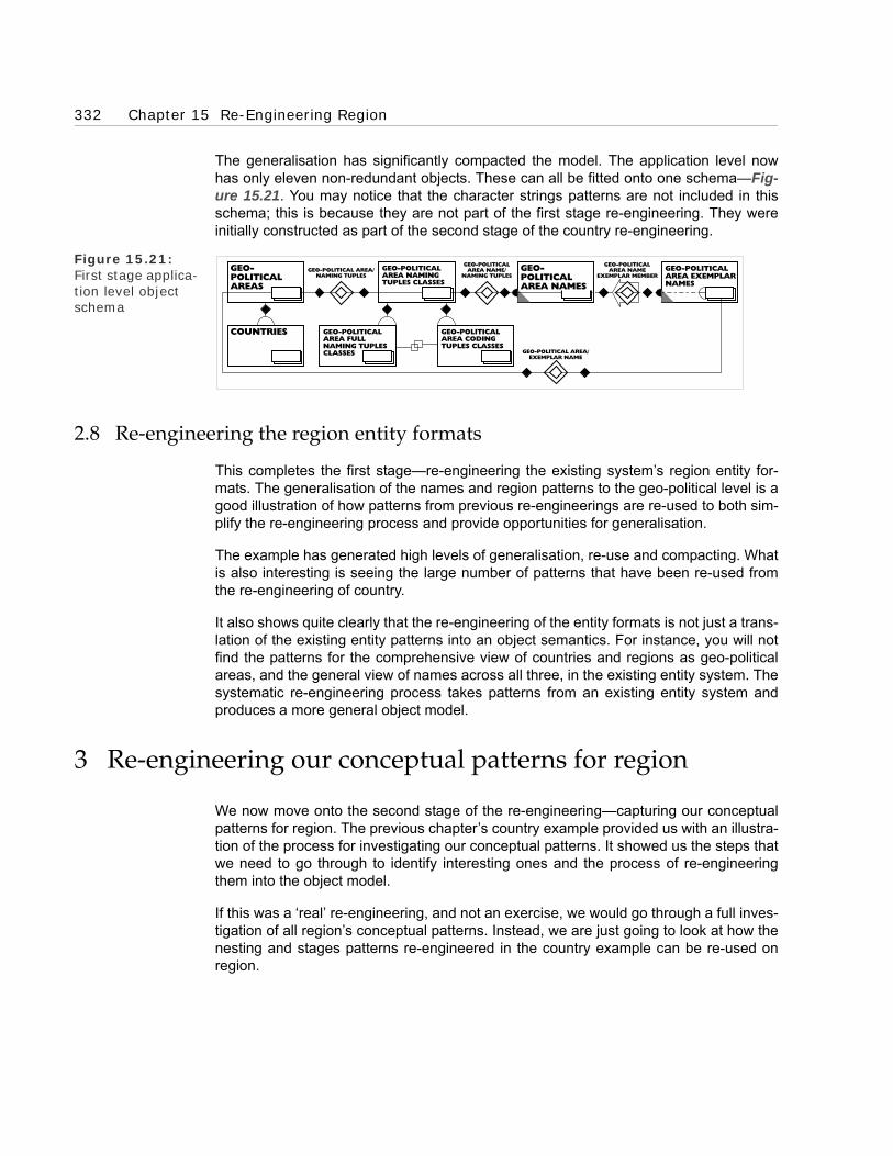
332 Chapter 15 Re-Engineering Region
The generalisation has significantly compacted the model. The application level nowhas only eleven non-redundant objects. These can all be fitted onto one schema—Fig-ure 15.21. You may notice that the character strings patterns are not included in thisschema; this is because they are not part of the first stage re-engineering. They wereinitially constructed as part of the second stage of the country re-engineering.
Figure 15.21: First stage applica-tion level object schema
2.8 Re-engineering the region entity formats
This completes the first stage—re-engineering the existing system’s region entity for-mats. The generalisation of the names and region patterns to the geo-political level is agood illustration of how patterns from previous re-engineerings are re-used to both sim-plify the re-engineering process and provide opportunities for generalisation.
The example has generated high levels of generalisation, re-use and compacting. Whatis also interesting is seeing the large number of patterns that have been re-used fromthe re-engineering of country.
It also shows quite clearly that the re-engineering of the entity formats is not just a trans-lation of the existing entity patterns into an object semantics. For instance, you will notfind the patterns for the comprehensive view of countries and regions as geo-politicalareas, and the general view of names across all three, in the existing entity system. Thesystematic re-engineering process takes patterns from an existing entity system andproduces a more general object model.
3 Re-engineering our conceptual patterns for region
We now move onto the second stage of the re-engineering—capturing our conceptualpatterns for region. The previous chapter’s country example provided us with an illustra-tion of the process for investigating our conceptual patterns. It showed us the steps thatwe need to go through to identify interesting ones and the process of re-engineeringthem into the object model.
If this was a ‘real’ re-engineering, and not an exercise, we would go through a full inves-tigation of all region’s conceptual patterns. Instead, we are just going to look at how thenesting and stages patterns re-engineered in the country example can be re-used onregion.
GEO-POLITICAL AREA/EXEMPLAR NAME
GEO-POLITICALAREAS
COUNTRIES
GEO-POLITICALAREA NAMINGTUPLES CLASSES
GEO-POLITICALAREA NAMES
GEO-POLITICALAREA EXEMPLARNAMES
GEO-POLITICAL AREA/NAMING TUPLES
GEO-POLITICALAREA NAME
EXEMPLAR MEMBER
GEO-POLITICALAREA CODINGTUPLES CLASSES
GEO-POLITICALAREA FULLNAMING TUPLESCLASSES
GEO-POLITICALAREA NAME/
NAMING TUPLES

3 Re-engineering our conceptual patterns for region 333
We apply country’s two patterns to region. Then (as with the patterns in the first stage ofregion’s re-engineering), we generalise them and their corresponding country patternsup to the geo-political areas level. It turns out that all these patterns can be generalisedinto a single geo-political areas pattern.
3.1 Nested regions
When we re-engineered country’s nesting pattern in Chapter 14 (illustrated in Figure14.11, I noted that it looked as though it could be re-used for other types of areas. It canbe; we now look at two examples:
• Region nested within region, and
• Country nested in region.
We start off, as we did in the country example, by assuming that the individual nestingpatterns are between individual regions and countries—not stages. We do not haveregion’s stages pattern until we re-engineer it in the next section.
3.1.1 Region nested in region
We start with the region nested in region pattern. The original sample of regions welisted in Table 15.1 are mutually exclusive; they do not nest. In fact, most computer sys-tem’s regions pattern assumes that regions do not nest. We came across a similarassumption when we re-engineered country’s nesting pattern. Both assumptions aremade for the same reason; the systems use both countries and regions as hooks tosummarise figures. Typically, countries provide the first level of summarisation, regionsthe second.
However in ‘reality’ we can and do have nested regions, just as we can and do havenested countries. For the re-engineering, we take a revised sample of regions, one thatprovides us with examples of nesting. This is given in Table 15.3. The new regions areshaded.
Region Name Region Code Nesting in Region
Europe EU
European Community EC
Far East FE
Middle East ME
North America NA
South America SA
Western Europe WE Europe
Table 15.3: Revised partial region listing

334 Chapter 15 Re-Engineering Region
When we re-engineer the Western Europe nesting in Europe pattern in Table 15.3, weget the object schema in Figure 15.22. This has the same pattern as nested countrywhole–part tuples (shown in Figure 14.11). As in the nested country pattern, the nestedregion whole–part tuples is redundant, derived from the regions class.
Figure 15.22: Region nesting in region
3.1.2 Country nested in region
We now turn our attention to the nesting pattern from country to region. This pattern islikely to be an existing system pattern. Many computer systems, certainly in my experi-ence, connect countries to regions. Normally their country entity format has a ‘belongingto region’ attribute type that relates each country to one region—like the one shown inTable 15.4.
If we update the original Partial Country Listing (Table 12.1) with the ‘new’ attributetype, we get the extended partial country listing in Table 15.5.
If we re-engineer this, we get the, by now familiar, nesting tuples pattern, this timebetween the countries and regions classes (shown in the schema in Figure 15.23). Youmay have noticed that the country nested in region whole–part tuples class is shown asderived—rather than redundant as in the earlier versions of the nesting pattern (forexample, Figure 15.22). This is because the tuple class has additional information in itscardinality faithfully reflecting the constraints in the entity format in Table 15.4. The car-dinality linking it to countries is constrained to optional-to-one; in other words, eachcountry can only ‘belong to’ one region. This is because (as we discussed in some
NESTED REGIONWHOLE-PART TUPLESREGIONS
REGIONS
EUROPEWESTERNEUROPE
THINGSWHOLE-PART TUPLES
Entity Type Attribute Type #1 Attribute Type #2 Attribute Type #3 Etc.
Country Country name Country code Belonging to region -
Table 15.4: Revised country entity format

3 Re-engineering our conceptual patterns for region 335
detail in Chapter 3) attributes, such as ‘belonging to region’ cannot reflect ‘many-to-many’ connections.
Figure 15.23: Country nested in region object schema
If you look carefully at the country listing in Table 15.5 and the region listing in Table15.3, you should be able to spot how the entity format constraint has made the listingincomplete. Something is missing for Germany, Italy and the United Kingdom. They arenot only part of Europe but also part of the European Community.
One simple workaround that may spring to mind is to make the European Community(EC) part of Europe (this gives a tree structure). But the example has been constructedso that this does not work. Turkey, a potential member of the EC (it has applied), is notpart of Europe. In other words, Europe does not necessarily contain all the European
Country Names Country Codes Belonging to Regions
Germany DM EU (Europe)
Italy IT EU (Europe)
Japan JP FE (Far East)
Turkey TK ME (Middle East)
United Kingdom UK EU (Europe)
United States US NA (North America)
Table 15.5: Extended partial country listing
REGIONS
REGION
UNITEDKINGDOM
FRANCE
COUNTRIES
COUNTRY
EUROPE
SOUTHAMERICA
COUNTRY NESTED IN REGIONWHOLE-PART TUPLES
Constrained'Optional-to-One'
Cardinality
THINGSWHOLE-PART TUPLES
Unconstrained'Optional-to-Mulitple'
Cardinality

336 Chapter 15 Re-Engineering Region
Community (it will not when Turkey joins the EC). And vice versa, the European Com-munity does not yet contain all of Europe.
So an accurate model needs to be able to reflect European EC members, such as Ger-many, as nested in at least two regions: Europe and the EC (this gives a lattice struc-ture). We revise the extended partial country listing in Table 15.5 to reflect this. Theresult is shown in Table 15.6.
We reflect this insight in the object model by relaxing the cardinality fromoptional-to-one to optional-to-multiple (shown in Figure 15.24). If you think about it, youwill realise that this less constrained cardinality applies to the other nesting patterns(country nested in country and region nested in region) as well. You may have noticedthat the relaxation of the cardinality has another effect. The country nested in regionwhole–part tuples class is now classified redundant—like the other nesting tuplesclasses. This is because its cardinalities no longer contain any additional information.
3.2 Region stages
We now extend the nesting pattern to include region stages, following the country pat-tern. We start by re-engineering one of the events that cause these stages, country join-ing region. This gives us the region stages pattern, which we use to generalise thenested pattern to the geo-political areas level.
Country names Country Codes Belonging to Regions
Germany DE EU (Europe)WE (Western Europe)EC (European Community)
Italy IT EU (Europe)WE (Western Europe)EC (European Community)
Turkey TK ME (Middle East)EC (European Community)
Japan JP FE (Far East)
United Kingdom GB EU (Europe)EC (European Community)
United States US NA (North America)
Table 15.6: Revised extended partial country listing

3 Re-engineering our conceptual patterns for region 337
Figure 15.24: Unconstrained country nesting in region object schema
3.2.1 Re-engineering the country joining region event pattern
We start with an example; the United Kingdom joining the European Community in1973. The re-engineering gives us the space-time map shown in Figure 15.25 and theobject schema shown in Figure 15.26. These have similar shapes to the country re-engineering example; the 1707 Act of Union event joining Scotland to the United King-dom (shown in Figures 14.12 and 14.13). This bodes well for the generalisation.
Figure 15.25: United Kingdom joining the Euro-pean Community space-time map
We then take the pattern up to class level. First for the country joining region events,giving us the schema in Figure 15.26 And then for the country and region stages, givingus the schema in Figure 15.27. Note that this combines the nesting and stages patternsand generalises them to the geo-political areas level.
COUNTRIES
COUNTRY
REGIONS
REGION
EUROPEANCOMMUNITY
ITALY
EUROPE GERMANY
COUNTRY NESTED IN REGIONWHOLE-PART TUPLES
Unconstrained'Optional-to-Mulitple'
Cardinality
THINGSWHOLE-PART TUPLES
EUROPEANCOMMUNITY(1957-1973)
EUROPEANCOMMUNITY
(1973-?)EUROPEAN
COMMUNITY
UKJOINING THE EC
UNITEDKINGDOM
UNITED KINGDOM(1973-?)
UNITED KINGDOM(1801-1973)

338 Chapter 15 Re-Engineering Region
Figure 15.26: Country joining region events object schema
Figure 15.27: Generalised geo-political areas & stages
3.2.2 Generalising to geo-political areas joining event
Our concern here is not with joining events. We only use them to provide us with anexample of the region stages pattern. However, it should be clear that the country join-ing region event pattern is one of the geo-political area joining event patterns. And that
REGIONS
REGION
COUNTRIES
COUNTRY
COUNTRYJOINING
REGION EVENTS
COUNTRY JOINING REGION TUPLES
EUROPEANCOMMUNITY
UNITEDKINGDOM
REGION IS JOINEDBY COUNTRY TUPLES
COUNTRY JOINSREGION TUPLES
UNITEDKINGDOM
JOINING THE EEC
COUNTRIES
UNITEDKINGDOM
UNITEDKINGDOM(1973-?)
EUROPEANCOMMUNITY
(1973-?)
GEO-POLITICALAREAS
EUROPEANCOMMUNITY
GEO-POLITICALAREAS ANDSTAGES
GEO-POLITICALAREA/STAGE
WHOLE-PART TUPLES
TEMPORAL WHOLE-PART TUPLES
THINGSWHOLE-PART TUPLES

4 Summary 339
country’s Acts of Union pattern (see Figure 14.17) is also one, although they haveslightly different shapes. Unlike the country joining region event pattern, the joining inthe Acts of Union pattern constructs a new country. In a ‘real’ re-engineering, we wouldre-engineer all the different patterns and then generalise them to the geo-political areajoining event, raising the pattern up to the geo-political areas level. But we have done allwe need to do for this worked example.
3.2.3 Geo-political area nesting/stage pattern re-use
If we consider the re-engineering so far, three main patterns have emerged. These are:
• the naming pattern,
• the geo-political area joining pattern, and
• the combined geo-political area nesting/stage pattern.
All of these provide us with good examples of the power of re-engineering. Take the lastpattern—geo-political area nesting/stage. The application level (the one that matters forsystem building) of the object model in Figure 15.27 is both more general and function-ally richer than the system from which it was re-engineered. It operates at the geo-polit-ical area level, and unlike the entity format, it can reflect:
• countries nested in countries,
• regions nested in regions, and
• countries nested in multiple regions.
In the next chapter, this pattern will be re-used again, generating morecompacting.
4 Summary
Our object model for spatial patterns is now more general and more powerful after thegeneralising of country’s conceptual patterns across regions and up to geo-politicalareas.
This example has shown, again, how much potential there is for re-use and generalisa-tion. The way in which country and region share patterns, and the ease with whichthese patterns combine, is uncanny. However, this can be explained in terms of ourstrong unconscious conceptual patterns for space. Uncovering these and making themexplicit and accurate in an object model is the purpose of the re-engineering.
The re-engineering of spatial patterns is not yet complete. In the next chapter, were-engineer our final example of a spatial pattern—address. However, this will demon-strate the re-usability of our general, object model, rather than enhance it.

340 Chapter 15 Re-Engineering Region

BOROBORO
Chapter 16Re-Engineering Bank Address
1 Introduction
2 Familiarising ourselves with bank address entity formats
3 Re-Engineering bank
4 Re-Engineering address
5 Nested address lines
6 Address joining events
7 Generalising name
8 An aspect of a pattern
9 Summary

342 Chapter 16 Re-Engineering Bank Address
1 Introduction
We have completed the re-engineering of the first two examples of spatial patterns;country and region. We now move onto the third and final example, address (see Fig-ure 16.1). This example illustrates the power of the basic object model for spatial pat-terns we have constructed. It shows how it can be re-used to capture the patterns foraddress, without any changes. It also provides us with an opportunity to construct atruly general model for the naming pattern.
Figure 16.1:Third and final of three examples of spatial patterns
As you are now quite familiar with the systematic re-engineering approach, we take ahigh level view. Even though address’s entity format is quite different from the earlierformats, its re-engineering follows the same basic pattern. Like before, we re-use pat-terns that we have already re-engineered; and, as you have now come to expect, thismeans we generalise them.
2 Familiarising ourselves with bank address entity formats
We start off, as always, by familiarising ourselves with specific examples of the entityformat we are going to re-engineer.
COUNTRY REGION ADDRESS
SPATIAL PATTERNSSPATIAL PATTERNS
Bank 001 BarcWest Bank 003 Chase Hanover Bank
Address Black Horse HouseMoorgateLondonUnited Kingdom
BarcWest TowerOld Broad StreetLondonUnited Kingdom
Bank 002 NatLand Bank 004 Banco di Guernsey
Address Listening Buildings21 MoorgateLondonEngland
54th FloorBarcWest TowerOld Broad StreetLondonEngland
Table 16.1: Partial address listing

3 Re-Engineering bank 343
Table 16.1 has a partial address listing that we use to do this. This is really a partialview of the address fields on the bank file—in other words, the attributes for the bankentity type. We call it bank address, because we are only interested in bank address’sspatial patterns. However, we must re-engineer bank to get to bank address.
From Table 16.1, we can work out that the entity format for bank address (bank) that isshown in Table 16.2.
3 Re-Engineering bank
We start by re-engineering, in outline, the bank elements of the entity format. In thisexample, we look at the bank entity type sign and its attribute types, bank full name andcode.
Figure 16.2: Banks object schema
Entity type Bank
Attribute type #1 Bank code
Attribute type #2 Bank full name
Attribute type #3 Address line 1
Attribute type #4 Address line 2
Attribute type #5 Address line 3
Attribute type #6 Address line 4
Attribute type #7 Address line 5
Table 16.2: Bank address entity format
BANKS
BANK
BARCWESTBANK
NATLANDBANK
CLASSES
CLASS

344 Chapter 16 Re-Engineering Bank Address
3.1 Re-engineering the bank entity type sign
We follow the rules and start by re-engineering the entity type sign before the attributetype signs. We are not really interested in bank because it is not a spatial or naming pat-tern; it is just a hook to hang address’s spatial patterns on; so, we move through there-engineering quickly. We re-engineer two individual banks and use these to constructthe banks class. We construct signs for these classes and get the object schema in Fig-ure 16.2.
3.2 Re-engineering bank’s full name and code attribute type signs
The bank full name and code attribute types are based on naming not spatial patterns,and they can be used to generalise the naming patterns in the model. We start by re-using the geo-political naming pattern (illustrated in Figure 15.21) as a template to con-struct the bank naming pattern. This gives us Figure 16.3. We will return to this schemalater in the chapter to generalise the naming patterns.
Figure 16.3: Bank naming tuples classes object schema
4 Re-Engineering address
We now move from bank to address and start to re-engineer the five address lines.When most people look at the lines of an address, they see a series of simple attributesigns. When we start analysing these, we will see a very different pattern—one that hasbeen severely distorted to fit into the attribute structure.
4.1 Re-engineering address line one attribute type sign
We follow the rules. We have already re-engineered the entity type sign; so, we canstart re-engineering the attribute type signs. We start with the address line one sign.
BANKNAMINGTUPLES CLASSES
TUPLES CLASSES
TUPLES
BANKNAMES
BODIES
BODY
BANKS
BANK
TUPLES
BANK/NAMING TUPLES
BANK NAME/NAMING TUPLES
CHARACTERSTRINGCLASSES
BANKFULL NAMINGTUPLES
BANKCODINGTUPLES
CHARACTERSTRINGS
EXEMPLARBANKNAMES
BANK/EXEMPLAR NAME
BANK NAMEEXEMPLAR MEMBER

4 Re-Engineering address 345
Table 16.3 has a partial listing of the individual attributes that we use to start the re-engineering.
4.1.1 Re-engineering the individual attribute signs
Following the rules, we re-engineer some individual address line one attribute signsbefore we re-engineer the attribute type sign. We pick BarcWest’s—Black HorseHouse—from Table 16.3. What does this sign refer to? Within the entity paradigm, it notonly refers to a ‘located at’ attribute of BarcWest but also implicitly to Black HorseHouse, where BarcWest is located. It is the implicit relational attribute sign described byFigure 16.4.
Figure 16.4: Bank ‘located at’ location attribute
We start the re-engineering with the Black Horse House entity. This is a building onMoorgate, one of the streets in the City of London. In the object paradigm it persiststhrough time and has a continuous four-dimensional extension; so, it is a physical bodyobject; in other words, a sub-class of the framework class, bodies.
Then we re-engineer the ‘located at’ connection it has with BarcWest Bank. This istransformed into the couple <BarcWest Bank, Black Horse House> belonging to a bank‘located at’ tuples class.
We pick another attribute sign from Table 16.3—NatLand Bank’s Listening Buildings—and re-engineer it. It follows the same pattern. The sign also refers to a building onMoorgate, one where NatLand Bank is located. We construct signs for both these
Bank Address line one
BarcWest Bank Black Horse House
NatLand Bank Listening Buildings
Chase Hanover Bank BarcWest Tower
Banco di Guernsey 54th Floor
Table 16.3: Partial address line one listing
PR
IMA
RY
LEV
EL
SEC
ON
DA
RY
LEV
EL
BLACKHORSEHOUSE
BANKLOCATION
BANK
BARCWEST
LOCATED AT
BLACK HORSE HOUSE
LOCATED AT

346 Chapter 16 Re-Engineering Bank Address
objects and their sub-class connection to bodies. This gives the object schema in Fig-ure 16.5.
Figure 16.5: Bank ‘located at’ tuples object schema
4.1.2 Re-engineering the attribute type sign
We now re-engineer the address line one attribute type sign. We have done part of thework with the bank ‘located at’ tuples class. We now need to construct a class for BlackHorse House and Listening Buildings. Address line one is not really a very informativename for the class, so we use ‘bank locations’. We construct a sign for it and get theobject schema in Figure 16.6. You will notice that bank locations is derived from thebank ‘located at’ tuples class.
Figure 16.6: Bank locations object schema
BANKS
BANK
BODIES
BODY
BARCWESTBANK
NATLANDBANK
located at
fronoi tac ol
LISTENINGBUILDINGS
BLACK HORSEHOUSE
BANK LOCATED ATTUPLES
BLACK HORSEHOUSE
LISTENINGBUILDINGS
BANKLOCATIONS
BANKS
BANK
rof noi tac ol
BANK LOCATEDAT TUPLES
locat ed at
BODIES
BODY

4 Re-Engineering address 347
If we think carefully, maybe stretching our imaginations a little, we can see that banklocations are a type of a geo-political area. They are not as big as countries or regions,but they work in the same way, occupying a defined space. Once we recognise this, wesee that bank locations is a sub-class of geo-political areas. This gives us an opportu-nity to generalise and compact.
We can generalise the ‘bank location for’ class place up the super–sub-class hierarchyto geo-political areas following the compacting pattern we have used in earlier exam-ples and discussed in Chapter 10 (illustrated in Figure 10.46). This makes bank loca-tions redundant; it is just those geo-political areas at which a bank is located (shown inthe object schema in Figure 16.7).
Figure 16.7: Compacted bank ‘located at’ tuples object schema
4.1.3 Address line one’s naming pattern
The address line one (or ‘located at’) attribute sign needs one last important bit of anal-ysis. Look again at BarcWest’s attribute sign. It contains the character string ‘BlackHorse House’. The particular characters in the string are important. They make up thefull name of the location. This means we need to revise the entity model of the attributein Figure 16.4; we have to add in the bank full names entity as shown in Figure 16.8.We now need to re-engineer this revised entity model.
Figure 16.8: Bank full name and location attrib-utes
GEO-POLITICALAREAS
BANKS
BANK
rof noi t acol
BANKLOCATIONS
BANK LOCATEDAT TUPLES
locat ed at
BODIES
BODY
PR
IMA
RY
LEV
EL
SEC
ON
DA
RY
LEV
EL
BARCWEST BLACKHORSEHOUSEFULLNAMES
BLACKHORSEHOUSE
BANKLOCATIONFULLNAMES
BANKLOCATION
BANK
FULL NAMELOCATION
BLACK HORSEHOUSE
'BLACK HORSEHOUSE'
FULL NAMELOCATION

348 Chapter 16 Re-Engineering Bank Address
However, if we look carefully at the patterns in our lexicon, we will see that the namingpattern has already been re-engineered. In the region example, we generalised thenaming pattern, including the full naming pattern, up to geo-political area level. Becausethe bank location is a sub-class of geo-political area, it inherits its full naming patterns.Bank location—as a geo-political area—already has a full name. This is illustrated inFigure 16.9. The re-engineering does not need to construct any new objects.
Figure 16.9: Bank locations full name object schema
However, it does introduce a new re-engineering pattern for attribute type signs, suchas bank location. We are familiar with the re-engineering pattern for relational attributetype signs, which gives us a tuples class and its place class. We are also familiar withthe re-engineering pattern for naming attribute type signs, which gives us a namingtuples class and its name class. Here, we have a re-engineering that combines the twopatterns—a sort of naming relational pattern. This is a useful pattern to have when re-engineering. Naming relational attribute type signs are common in entity based sys-tems.
This also is a good illustration of the semantic accuracy required when re-engineering. Ifwe had not been careful, we could have easily stopped the analysis at bank location.Then we would not have recognised that there was a full name pattern to re-engineer—even though it now stares us in the face.
4.2 Re-engineering the other address lines attribute type signs
Because the re-engineering of the other address lines follows a similar pattern, we do ithere in bulk. This also helps us to see a connecting pattern between the lines.
Like bank locations, with a little stretching of the imagination, we can see the otheraddress lines as full names for geo-political areas. BarcWest’s ‘Old Broad Street’ and‘London’ are larger than bank locations and smaller than countries or regions, but stillthe same type of object. Address line four, ‘United Kingdom’, is a country—so, by ourprevious re-engineering, already a geo-political area. This has other implications thatwe will examine later.
NATLANDBANK FULLNAMES
GEO-POLITICALAREAS FULLNAMES
NATLANDBANK
GEO-POLITICALAREA FULL NAMINGTUPLES CLASSES
GEO-POLITICALAREAS
BANKLOCATIONS
BANK LOCATIONFULL NAMINGTUPLES CLASSES
NATLAND BANKFULL NAMING
TUPLES
GEO-POLITICAL AREA/FULL NAMING TUPLES
GEO-POLITICAL AREAFULL NAME/
FULL NAMING TUPLES
BANKLOCATIONFULL NAMES
fully named b y
se man yll uf

5 Nested address lines 349
These other address lines do not have exactly the same pattern as address line one.Unlike it, they do not have a ‘located at’ connection with a bank, and so are not banklocations. Otherwise, their patterns are the same. At the application level, the otheraddress lines are geo-political areas, and so, like address line one, inherit its full namingpatterns. This means we do not need to re-engineer any new application level objectsfor them (illustrated by the schema for BarcWest’s address in Figure 16.10).
Figure 16.10: BarcWest’s address object schema
5 Nested address lines
We have re-engineered all the explicit patterns for these bank address lines, but there isstill one vital implicit pattern that our accurate semantic analysis needs to pick up.
If we look at the listing of addresses in Table 16.1 again, it appears that there cannot beanything special about which line the objects appear on. For example, one of them,‘BarcWest Tower’, appears as address line one in Chase Hanover’s address and asaddress line two in Banco di Guernsey’s address. It cannot be intrinsically both a lineone and a line two object.
However, the order of the lines is important. This is easy to show; look at the addressesin Table 16.4. They are clearly not valid addresses; yet, all I have done is move theposition of the lines. The reason they are not valid addresses is the positioning of thelines reflects an implicit pattern, and changing the order of the lines breaks it. We are so
BLACK HORSE HOUSE MOORGATE LONDON
UNITEDKINGDOM
BANKLOCATIONS
GEO-POLITICALAREAS
GEO-POLITICALAREA FULL NAMINGTUPLES CLASSES
GEO-POLITICALAREA FULLNAMES
GEO-POLITICALAREA FULL NAME/
FULL NAMINGTUPLES
GEO-POLITICALAREA/FULL
NAMING TUPLES

350 Chapter 16 Re-Engineering Bank Address
familiar with this implicit pattern that we automatically read it in. We only notice that itexisted when it is not there.
5.1 Implicit whole–part tuples
A little thought shows that the order of the address lines implies a whole–part connec-tion between them. For example, because London is on the line before United Kingdom,this implies it is part of United Kingdom. We broke the order of this whole–part patternwhen we moved the lines around. Figure 16.11 shows an entity view of the whole–partpattern for BarcWest’s address.
Figure 16.11: BarcWest’s address’s implicit whole–part pat-terns
This is not how Aristotle’s entity paradigm structure was originally meant to work. It hasbeen ‘bent’. We are now so familiar with this ‘bending’ that we automatically supply theimplicit whole–part patterns. However, we do not need to do any bending in the objectparadigm. In fact, the strong reference principle demands that we map the whole–partconnections directly and explicitly into the model. Figure 16.12 illustrates the result.
Bank 001 BarcWest Bank 003 Chase Hanover Bank
Address United Kingdom
MoorgateBlack Horse HouseLondon
London
BarcWest TowerUnited KingdomOld Broad Street
Table 16.4: Altered address lines
BARCWESTBANK
BLACK HORSEHOUSE
MOORGATE
LONDON
UNITEDKINGDOM
MOORGATE
MOORGATELONDON
LONDON
UNITEDKINGDOM
BLACK HORSEHOUSE
BLACK HORSEHOUSE
ADDRESS LINE 1
ADDRESS LINE 2
ADDRESS LINE 3
ADDRESS LINE 4
CONTAINS
CONTAINS
CONTAINS

5 Nested address lines 351
Figure 16.12: BarcWest’s address’s whole–part tuples object schema
5.2 More accurate whole–part pattern
You have probably recognised that this modelling of the whole–part pattern is not asaccurate as it should be. In Chapter 14, when we re-engineered country’s nestedwhole–part patterns, we saw how Scotland was only ‘part of’ the Great Britain for part ofits life. In other words, a stage of Scotland—and not Scotland—was part of the UnitedKingdom. This is illustrated in Figure 14.12.
Figure 16.13: More accurate whole–part pat-terns
The address lines are geo-political areas and so could have a similar pattern to Scot-land. Though it is unlikely, there is no reason why Black Horse House should not bebought by a foreign billionaire and transported to another country. In this case, BlackHorse House would have a similar pattern to Scotland. It would only be part of Moorgatefor part of its life. In other words, a stage (state) of Black Horse House would be part ofMoorgate. We do not need a new pattern to capture this. We can re-use the geo-politi-cal areas and stages nesting pattern. Figure 16.13 illustrates what the more accuratemodel looks like.
BLACK HORSEHOUSE
MOORGATE LONDON ENGLAND
part of
contains
GEO-POLITICAL AREAWHOLE-PART TUPLES
GEO-POLITICALAREAS
BLACK HORSEHOUSE
(?-1997)
BLACK HORSEHOUSE MOORGATE
GEO-POLITICALAREAS &STAGES
part of
contains
GEO-POLITICAL AREA/STAGEWHOLE-PART TUPLES

352 Chapter 16 Re-Engineering Bank Address
5.3 Re-engineering the same object twice
When we were re-engineering the other address lines, we noted that one of the addresslines—BarcWest’s address line four—was the full name for a country—‘United King-dom’. This raises an important point. It is impractical to apply the strong reference prin-ciple consistently in the constrained entity environment. So, sometimes, there is morethan one sign for an entity. This is a case in point. United Kingdom on the country fileand United Kingdom in BarcWest’s address both refer to the same entity.
Under the strong reference principle, we should re-engineer these two entity signs intoone sign in the object model. Where there is duplication in the existing system, we donot replicate it in the model. So we do not re-engineer a new sign in the model for theUnited Kingdom, but re-use the existing one. Figure 16.14 shows the re-engineeringpattern.
Figure 16.14: United Kingdom re-engineering pattern
Duplication of signs occurs with a vengeance within address. Consider the list ofaddress line attributes from Table 16.1 in Table 16.5. It is plain that the four Londons(and three Englands) in the various addresses are full names for the same entities. Fig-ure 16.15 shows what the re-engineered undistorted de-duplicated model looks like fortwo of the addresses.
This de-duplication leads to compacting. Transforming two (or more) signs in the entitymodel into one object sign makes the model smaller and leaner. It also makes mainte-nance of the implemented system easier. In the existing system, when an address entitychanges its full name then this change has to be applied to all its full name signs. Let’ssay London changed its name to Londres; then, every bank address line that contains‘London’ would need to be changed. There are four of these in this small example; therecould be hundreds, or even thousands, more in a working entity oriented system. How-
UNITED KINGDOMATTRIBUTE SIGN
ENTITYSYSTEM
UNITED KINGDOMSUBSTANCE
UNITED KINGDOMOBJECT
ENTITYDOMAIN
OBJECTDOMAIN
UNITED KINGDOMSIGN
OBJECTMODEL
UKENTITY SIGN
UK
BANK
UK
ADDRESSUNITED
KINGDOM
COUNTRY

5 Nested address lines 353
ever, in a system based on the object model, there would only be one and so thechange would only need to be done once.
Figure 16.15: BarcWest and Chase Hanover Bank addresses
Figure 16.16: Moorgate object schema
Bank Address Line No. Location
BarcWest Bank 3 London
NatLand Bank 3 London
4 England
Chase Hanover Bank 3 London
Banco di Guernsey 4 London
5 England
Table 16.5: Selected address line attributes listing
BLACK HORSEHOUSE
LONDON
BARCWESTTOWER
MOORGATE
OLD BROADSTREET
UNITEDKINGDOM
GEO-POLITICALAREAS &STAGES
GEO-POLITICAL AREA/STAGEWHOLE-PART TUPLES
LISTENINGBUILDINGS
LONDON
BLACK HORSEHOUSE
21 MOORGATE
MOORGATE
GEO-POLITICALAREAS &STAGES
GEO-POLITICAL AREA/STAGEWHOLE-PART TUPLES

354 Chapter 16 Re-Engineering Bank Address
5.4 One name referring to two objects
Addresses contain a number of implicit patterns and it can take some time to uncover.For example, one of the addresses in Table 16.1 contains another implicit pattern. Con-sider two address lines; BarcWest Bank’s address line two—‘Moorgate’—and NatLandBank’s address line two—‘21 Moorgate’. We automatically recognise that BarcWest andNatLand Banks are both located on the same street—Moorgate. However, this recogni-tion has not been captured by the re-engineering (shown in their model in Figure16.16). Listening Buildings is not signed as a part of Moorgate.
To capture this, we have to divide the name ‘21 Moorgate’ into two names—‘21’ and‘Moorgate’. The name ‘21’ is another way of indicating the NatLand Bank’s location, Lis-tening Buildings. It is not a full name, so we treat it as a code. ‘Moorgate’ is a duplicationof BarcWest Bank’s address line two—Moorgate—the full name for a street. The newmodel is shown in Figure 16.17. This clearly shows that the two buildings are bothlocated in Moorgate.
Figure 16.17: New Moorgate object schema
6 Address joining events
When we re-engineered country and region, the nesting pattern went hand in hand withjoining events. For example, the stage of Scotland that is part of Great Britain was cre-ated by the 1707 Scottish Act of Union Joining Event. When we re-engineered region,we generalised the patterns to the geo-political area level. Addresses, as geo-politicalareas, inherit the joining event patterns.
These patterns are useful for addresses. When counties’ boundaries are moved andtowns end up in new counties—a reasonably regular occurrence nowadays—this is ajoining event. It can be modelled re-using the geo-political area joining patterns.
7 Generalising name
We now turn our attention from spatial to naming patterns. At the beginning of this chap-ter, when we were re-engineering the bank full name and code attribute type signs, I
GEO-POLITICALAREA CODINGTUPLESCLASSES
GEO-POLITICALAREA FULLNAMING TUPLESCLASSES
MOORGATE
LISTENINGBUILDINGS
BLACK HORSEHOUSE
'21'CODES CLASS
'LISTENINGBUILDINGS'FULL NAMESCLASS
GEO-POLITICALAREAS ANDSTAGES
GEO-POLITICALAREA/STAGE
WHOLE-PART TUPLES

7 Generalising name 355
noted that we would use their object model to generalise the naming pattern. We do thisnow; we generalise naming above and away from geo-political areas and bank. Thisgives us a separate re-usable web of completely general naming patterns.
7.1 A general model for naming patterns
The bank and geo-political area naming models are the same shape. It seems likelythat all naming models share the same shaped pattern. So there is an opportunity togeneralise to a naming pattern. We take this now. We start with the general namingtuple and build up its connecting patterns. We derive from it the class of namedobjects—those objects that are connected by the named object/naming tuple classplace. In theory, any object can be named; so, this named object class is a sub-class ofthe framework class, objects. We also derive the names class—those objects that areconnected by a class place link to the name/naming tuples class. This names class is asub-class of character strings.
This gives us the general model for the naming pattern shown in Figure 16.18. As youcan see, it is independent of both geo-political areas and banks. Furthermore, it has 15objects of which only 10 are specific to names. This pattern is ubiquitous; its model willbe re-used a large number of times in almost every re-engineering. Therefore, it makessense to put its model into the general lexicon (which we discussed in Chapter 11 ) byclassifying its objects as framework level. As you can see, this has been done in Figure16.18.
Figure 16.18: Generalised nam-ing tuples object schema
Undoubtedly, when the naming model is re-used, there will be opportunities to enhanceit. For example, currency symbols, such as ‘£’ and ‘$’, which are not currently cateredfor, might be found as attributes of the currency entities. These would be generalisedinto the naming pattern. They would probably be generalised to a new sub-class of thenaming tuples class—the symbol naming tuples classes. In this way, the model natu-rally grows as we expand our explicit understanding of the naming pattern.
7.2 Compacting with the general naming model
This general naming model leads to substantial compacting. Most of the systems that Ihave worked on have had well over 100 entity types (files). Almost all of these had
CHARACTERSTRINGS
OBJECTS
OBJECT
TUPLES TUPLES CLASSES
TUPLES
CHARACTERSTRINGCLASSES
NAMEDOBJECTS
NAMES EXEMPLARNAMES
NAMINGTUPLESCLASSES
NAMED OBJECT/NAMING TUPLES
NAME/NAMING TUPLES
NAMED OBJECT/EXEMPLAR NAME
FULL NAMINGTUPLES
CODINGTUPLES
NAMEEXEMPLAR MEMBER

356 Chapter 16 Re-Engineering Bank Address
name attribute type;, many have had two (a full name and code), some have had more.So there would usually be well over 200 name attribute types in a system. We re-engi-neered these by transforming their entity types into classes that were sub-classes of thenamed objects class. Because they then inherited the general naming pattern, no otherre-engineering was necessary. As well as simplifying the re-engineering process, thiscompacts the model. The original 200 name attribute types are compacted into thenaming pattern’s 10 objects. Furthermore, adding additional name attribute types wouldnot increase the size of the model.
8 An aspect of a pattern
The address format was originally designed for paper and ink technology; it fits naturallyonto the cover of an envelope. It also transfers effortlessly into the entity paradigm’sframework. The re-engineering of address gives us a good insight into how much somepatterns have had to be distorted to fit onto paper and ink technology and into the entityparadigm. The patterns we end up with in the object model are very different from thepatterns we start with in the existing system.
These radically changing patterns can seem odd. I find it useful to think of them in termsof this analogy. Consider a three-dimensional pyramid, but assume that we can onlysee it from one aspect at a time. If we look from the top—Figure 16.19 (a)—it has a dia-mond outline. If we look at if from the ground, directly facing one side—Figure 16.19(b)—we see a triangle. If we move so that we are not directly facing a side – Figure16.19 (c)—we see an odd shaped four-sided figure. Because we can only see the pyra-mid in two dimensions, we only see one aspect of it at one time.
Figure 16.19: Aspects of a three-dimensional pyra-mid
Assume now we were to try and build a model of the pyramid. We would not build threemodels, one for each of the aspects; we would build one model of the complete pyra-mid. We could re-create the aspects we looked at earlier by taking a particular view ofour three-dimensional model. The radical differences between the entity patterns andthe object patterns are like the radical differences between any one of the two-dimen-sional views and the three-dimensional model. In the same way that only looking at thepyramid in two-dimensions views gives us an aspect, so the two-dimensional con-straints of the entity paradigm produce partial views of business objects.
(c) Multiple Side View(a) Top View (b) Single Side View

9 Summary 357
9 Summary
This re-engineering of address has completed the basic object model for spatial pat-terns; it is ready for re-use in future re-engineering projects. More importantly, this andprevious chapters have given us a feel for how the systematic re-engineering processworks. We now know the standard steps in the process and are familiar with a numberof common re-engineering patterns.
As discussed in the previous section, address has also given us a useful example ofhow using the entity paradigm (the paradigm behind address) can distort the overallshape of business objects. We have seen how fitting address into the entity paradigm’sconstraints fixes one particular view. We have also seen how re-engineering frees itfrom that constraint, giving us a full rounded view of the business objects. Furthermore,we have seen how general objects that enable substantial re-use, such as the namingobjects, are constructed.
In the next chapter, we re-engineer some of the entity paradigm’s temporal patterns intoan object model for time. Like space, time is fundamental to most business paradigmsand so the model is very re-usable.

358 Chapter 16 Re-Engineering Bank Address

BOROBORO
Chapter 17Re-Engineering Time
1 Introduction
2 Re-engineering an existing system’s bank holiday entity format
3 Re-engineering day
4 Re-engineering bank holiday
5 Re-engineering an existing system’s weekend entity formats
6 Re-engineering our conceptual patterns for bank holiday and weekend
7 The object model for temporal patterns
8 Summary

360 Chapter 17 Re-Engineering Time
1 Introduction
In the last five chapters, we constructed an object model for spatial patterns by re-engi-neering low-level three entity formats. We now turn to the similar task of constructing ageneralised object model for temporal patterns. We do this by re-engineering the twolow-level entity formats; bank holiday and weekend (Figure 17.1). Their re-engineeringreveals temporal patterns that are very general and will be found in most systems. Now,that we are familiar with the steps in the re-engineering process, we focus on what isbeing re-engineered.
Figure 17.1:Two examples of temporal patterns
The spatial patterns that we re-engineered in the previous examples were reasonablyintuitive. The analysis can be seen as, in some ways, a clarification of our common-sense views of space. The re-engineering of time is different. The object paradigmoffers such a radically different view of time and temporal patterns that our intuitionscannot give us any sensible guidance (as we saw when we examined its semantics inChapter 8). Even though the temporal model we re-engineer in this chapter provides agood explanation of our everyday uses of temporal terms, the patterns themselves ini-tially seem odd. This is a good sign; it is to be expected from a radical re-engineering.
2 Re-engineering an existing system’s bank holiday entity format
We start by re-engineering the bank holiday entity format. As usual we start by lookingat some of the existing entities. Table 17.1 gives us a Partial Bank Holiday Listing.
BANKHOLIDAY WEEKEND
TEMPORAL PATTERNSTEMPORAL PATTERNS
Country Code Date
UK 09-Apr-93
UK 03-May-93
US 18-Jan-93
US 16-Feb-93
Table 17.1: Partial bank holiday listing

2 Re-engineering an existing system’s bank holiday entity format 361
From this, we can deduce the entity format shown in Table 17.2.
2.1 Bank holiday as a relational entity
Bank holiday is a relational entity type. It is derived from the entity types, country andday. It is not a pseudo entity type, such as the employee–project we discussed in Chap-ter 3 (see Figure 3.24). Those were a workaround solution to the problem of handlingmany-to-many relational attribute types in the entity paradigm. Unlike them, bank holi-day is real. We will confirm this when we see the object that it is transformed into. But,like the pseudo entity types, bank holiday’s two attribute types link it to the entity typesfrom which it is derived (illustrated in Figure 17.2).
Figure 17.2: Bank holiday rela-tional entity
When re-engineering a real or pseudo relational entity type, we follow a similar rule tore-engineering a relational attribute. We re-engineer the related entity types before were-engineer the relational entity type. So here we re-engineer country and day beforewe re-engineer bank holiday. Country has already been re-engineered in a previousexample; so, we only need to re-engineer day.
US 31-May-93
Entity Type Attribute Type #1 Attribute Type #2
Bank holidays Country code Date
Table 17.2: Bank holidays entity format
Country Code Date
Table 17.1: Partial bank holiday listing
PR
IMA
RY
LEV
EL
SEC
ON
DA
RY
LEV
EL
9thAPRIL1993
UNITEDKINGDOM/9-APR-93BANKHOLIDAY
19-APR-93
GB
DAY
UNITEDKINGDOM
COUNTRY BANKHOLIDAY
DATE
COUNTRY
COUNTRY
DATE

362 Chapter 17 Re-Engineering Time
3 Re-engineering day
Most computer systems do not have a day file (corresponding to the entity type shownin Figure 17.2) with a record (entity) for each day. In other words, the day (or date)entity is not usually found explicitly implemented in most computer systems. However, itis there, but implemented implicitly. The individual day entities are deduced from theday code attributes of other entities. It can be thought of as an entity implemented as aprocess (as we discussed in Chapter 2 ).
We need to re-engineer this implicit entity. The easiest way to do this is to construct anexplicit entity format for it and subject this to the standard re-engineering procedure.Once the format is constructed, we can continue as usual. We familiarise ourselves withthe entity format by looking at some examples of what we are going to re-engineer.Table Table 17.3 gives us a partial day listing.
From this, we deduce the entity format shown in Table 17.4.
3.1 Re-engineering the day entity type sign
In this example, we only re-engineer the day entity type sign. We do not need to re-engi-neer its associated day code attribute type sign. If we were to re-engineer it, then itwould fall under the naming pattern re-engineered in the previous chapters. For the dayentity type sign, we follow the second rule and re-engineer a couple of day entitiesbefore the day entity type.
Day Code
09-Apr-93
10-Apr-93
11-Apr-93
12-Apr-93
13-Apr-93
14-Apr-93
Table 17.3: Partial day listing
Entity Type Attribute Type #1
Day Day Code
Table 17.4: Day entity format

3 Re-engineering day 363
We start with an individual day selected from Table 17.3—9th April 1993. From an entitypoint of view, the sign refers to a period of time—a day. It starts just after midnight of the8th April 1993 and continues until midnight 9th April 1993.
Our examination of the object semantics of temporal patterns, in Chapter 8, tells uswhat object this entity is transformed into. It is a temporal stage of the whole ofspace-time. It is every part of space-time for the period that starts just after midnight ofthe 8th April 1993 and continues until midnight 9th April 1993. Because it persiststhrough time, it is a physical body. A space-time map of the object is given in Figure17.3, an object schema in Figure 17.4. Other days can be re-engineered into similarpatterns.
Figure 17.3: Space-time map for 9th April 1993
Figure 17.4: 9th April 1993 object schema
This is a very different way of seeing time, but we can translate the way we talk into it.We normally say ‘today is the 9th April’. This can be understood as ‘now is a temporalpart of the four-dimensional object 9th April’. This is a mouthful and so not a practicalalternative for everyday conversation.
3.1.1 Re-engineering the entity type sign
We follow the normal re-engineering pattern. The entity type sign is re-engineered intothe class of objects that the entity signs were re-engineered into. This gives us the classdays. The members of this days class divide the four-dimensional space-time ‘sausage’into regular day long slices. This is illustrated in the space-time map in Figure 17.5 andmodelled in Figure 17.6.
00:00:019th APRIL 1993
24:00:009th APRIL 1993
SPACE-TIME
9thAPRIL1993
BODIES
9thAPRIL1993

364 Chapter 17 Re-Engineering Time
3.2 Re-engineering other time periods
We can extrapolate this pattern to give an object-oriented view of other time periods,such as months and years. These divide the space-time ‘sausage’ into larger monthand year long temporal slices (shown in the space-time map in Figure 17.7). Thesmaller slices are temporal parts of the larger slices. So, in the object paradigm, a day ispart of a month and a month part of a year in the same way as my hand is a part of myarm.
Figure 17.5: The days class
Figure 17.6: Days object schema
SPACE-TIME
9thAPRIL1993
9thAPRIL1993
10thAPRIL1993
10thAPRIL1993
11thAPRIL1993
11thAPRIL1993
DAYS
10thAPRIL1993
9thAPRIL1993
11thAPRIL1993
DAYS
DAY
BODIES
BODY

4 Re-engineering bank holiday 365
Figure 17.7: Year, month and day space-time Map
All three classes can be regarded as members of a calendar periods class (shown inthe object schema in Figure 17.8). This gives us one of the groups of basic temporalpatterns we need for our temporal object model. The remainder of the re-engineeringwill give us the rest.
Figure 17.8: Calendar periods object schema
4 Re-engineering bank holiday
Now that we have re-engineered country and day, we can re-engineer the derived rela-tional entity, bank holidays.
4.1 Re-engineering the bank holiday entity type sign
We follow our rules and start with an entity, an individual bank holiday. Let’s start withthe 9th April 1993 in the United Kingdom, the first entry in Table 17.1. What does thisrefer to? From an entity point of view, it is a period of time—a day— that is a bank holi-day in the United Kingdom.
1993APRILSPACE-TIME
9th
YEARS
YEAR
1993 APRIL 9th
MONTHS
MONTH
DAYS
DAY
CALENDARPERIODS
THINGSWHOLE-PART TUPLES

366 Chapter 17 Re-Engineering Time
Figure 17.9: United Kingdom’s 9th April bank hol-iday space-time Map
We know what this bank holiday’s related objects, United Kingdom and 9th April 1993,are. These give us a clue to what the bank holiday object is. It is the intersection (over-lap) of the two objects the United Kingdom and the 9th April—in other words, that bit ofspace-time that is part of both objects. This is illustrated in the space-time map in Fig-ure 17.9. This shows that the intersected bank holiday object is constructed from theother two objects.
We follow the standard pattern of re-engineering for the entity type sign. It re-engineersinto the class of objects that its entity signs were re-engineered into; this is the bank hol-idays class. All the members of this class are logically dependent on the whole–parttuples that they have with members of the countries and days classes. This makes themembers derived, but not the class itself. This is shown in the object schema in Figure17.10.
Figure 17.10: Bank holidays object schema
Notice that the bank holiday’s connections to the intersecting objects are whole–part;they are structural connections between extensions. These define the individual bankholiday object and so we classify it as derived. The re-engineering of the other bank hol-idays follows the same pattern.
SPACE-TIME 9th
APRIL1993
UNITED KINGDOM9th APRIL 1993
UNITEDKINGDOM
UNITEDKINGDOM9th APRIL
1993
BANKHOLIDAYS
UNITEDKINGDOM
9th APRIL1993
DAYSCOUNTRY/BANK HOLIDAYWHOLE-PART TUPLES
DAY/BANK HOLIDAYWHOLE-PART TUPLES
THINGSWHOLE-PART TUPLES
COUNTRIES

5 Re-engineering an existing system’s weekend entity formats 367
It may seem odd that a bank holiday is a physical object. But it gives a good explanationof the way we talk. If we are travelling through a country on a bank holiday, we say, ‘it isa bank holiday here’. In object-oriented English, this translates into ‘my here object ispart of the bank holiday object’. If we were to travel straight onto the next country, wewould say, ‘it is not a bank holiday here’. This translates as ‘my here object is not part ofa bank holiday object’.
4.2 State of the object model for temporal patterns
This completes the re-engineering of the bank holiday entity formats. It has given us areasonable foundation for the object model of temporal patterns. The calendar periodsare useful general patterns that can be re-used in most re-engineerings. The bank holi-day pattern is lower level, but still reasonably useful. It also links us in to the spatial pat-terns’ object model by way of countries. Later on in this chapter, we will see how we cangeneralise this link up to geo-political areas.
5 Re-engineering an existing system’s weekend entity for-mats
We now turn to the re-engineering of the second example—the weekend entity format.We start, as usual, by looking at the existing entities; a partial list is given in Table 17.5.
From this, we get the entity format in Table 17.6.
Country Indicators
Code Monday Tuesday Wednesday Thursday Friday Saturday Sunday
UK No No No No No Yes Yes
US No No No No No Yes Yes
Table 17.5: Partial weekend listing
Entity Type Weekend
Attribute Type #1 Country code
Attribute Type #2 Monday indicator
Attribute Type #3 Tuesday indicator
Attribute Type #4 Wednesday indicator
Attribute Type #5 Thursday indicator
Attribute Type #6 Friday indicator
Table 17.6: Weekend entity format

368 Chapter 17 Re-Engineering Time
5.1 Re-engineering the weekend entity type sign
We follow the rules and pick an individual weekend entity sign to re-engineer—theUnited Kingdom (coded as UK) from the partial listing in Table 17.5. This indicates thatthe United Kingdom’s weekend is Saturday and Sunday. Even though Saturday andSunday appear as individual entities in this system, they are entity types. Their entitiesare individual Saturdays and Sundays—such as the 6th and 7th May 1995. This meansthat the United Kingdom entry we selected from Table 17.5 is also an entity type withentities.
A partial listing of these entities—particular United Kingdom weekends—is given inTable 17.7. We start re-engineering at this level and work our way up to the selectedentity sign. We select an example weekend—the 6th/7th May 1995—to re-engineer.
Figure 17.11: United Kingdom’s 6th/7th May week-end space-time map
The particular weekends shown in Table 17.7 have a similar pattern to bank holidays.They are a particular period of two days in a particular country—the United Kingdom.They each contain a particular Saturday and a particular Sunday. This pattern of whole–part connections is shown in the space-time map in Figure 17.11. All of the United King-dom’s weekends share the same pattern.
Attribute Type #7 Saturday indicator
Attribute Type #8 Sunday indicator
Table 17.6: Weekend entity format
Weekends Dates Days
#101 6th/7th May 1995 Saturday/Sunday
#102 13th/14th May 1995 Saturday/Sunday
#103 20th/21st May 1995 Saturday/Sunday
Table 17.7: Particular United Kingdom weekends partial listing
6th/7th MAY 1995WEEKEND
UNITEDKINGDOM
UNITED KINGDOM6th/7th MAY 1995 WEEKEND
SPACE-TIME

5 Re-engineering an existing system’s weekend entity formats 369
Figure 17.12: United Kingdom’s weekends object schema
If we generalise the pattern up to class level, we get the object schema in Figure 17.12.Notice how all the tuples have a structural extension element.
The particular Saturday—the 6th May 1995—belongs to the Saturdays class: the par-ticular Sunday—the 7th May 1995—belongs to the Sundays class. We can generalisethis pattern across all the days of the week. This gives us the object schema in Figure17.13. This is a useful addition to the temporal object model—this general group ofobjects is common in systems. If we want to, we can also add the sign for a weeks classto the model, where each week is the fusion of seven consecutive days, starting with aMonday.
Figure 17.13: Days of the week
We are now ready to re-engineer the entity type sign. It is transformed into a class ofclasses, the country’s weekends class, which has, for instance, the U(nited) K(ing-dom)’s weekends class as a member. The UK weekends class’s tuples are generalisedinto tuples classes (shown in Figure 17.14). This is similar to the naming tuples’ gener-alisation into naming tuples classes shown in Figure 12.33.
SATURDAYS
SATURDAY
UK WEEKEND/SUNDAYTUPLESSUNDAYS
SUNDAY
UNITEDKINGDOM
7TH MAY 1995
6TH MAY 19956TH/7TH
MAY 1995UK WEEKEND
UK WEEKENDS
UKWEEKEND
UNITED KINGDOM/WEEKENDWHOLE-PART TUPLES
UK WEEKEND/SATURDAY TUPLES
SATURDAYS
6TH MAY 1995 7TH MAY 1995 8TH MAY 1995 9TH MAY 1995 10TH MAY 1995 11TH MAY 1995 12TH MAY 1995
SATURDAY
SUNDAYS
SUNDAY
MONDAYS
MONDAY
TUESDAYS
TUESDAY
WEDNESDAYS
WEDNESDAY
THURSDAYS
THURSDAY
FRIDAYS
FRIDAY
DAYS OFTHE WEEK

370 Chapter 17 Re-Engineering Time
Figure 17.14: Country week-ends class object schema
The generalisation of UK weekends’ temporal–whole–part tuples raises a notationissue. Temporal–whole–part tuples link individual objects—not classes. At the UK week-ends level, this does not pose a problem because its members are at the individualobject level. However, it does pose a notation problem at the level of country weekends,which is a class of classes. Here, there is no individual object to be a whole–part of.This is resolved by using a combination of existing components to construct a new com-posite sign, the temporal–whole–part-member-of sign (shown in Figure 17.14).
5.2 The status of the object model for temporal patterns
This completes the re-engineering of the weekend entity format. It has added twoimportant new groups of patterns to the object model—days and country weekends.These are, like calendar periods, useful general patterns that are found in many sys-tems. Even though the country weekend pattern is lower level, and so less common, itis still useful. It also usefully illustrates how patterns are generalised up the class–mem-ber hierarchy as well as the super–sub-class hierarchy.
It is worth noting that a number of the temporal patterns captured in the model, such asparticular UK weekends and days of the week, are traditionally implemented as datecalculation processes. This is an example of the point first raised in Chapter 2 ; that is,data and process in the information system are not a direct reflection of bodies andevents in the real world. Like this case, individual bodies can be implemented as pro-cesses.
6 Re-engineering our conceptual patterns for bank holiday and weekend
So far we have constructed the temporal object model by re-engineering entity formatsfrom existing systems. We now look at some of the more complex conceptual patternsthat we can re-engineer to make the model substantially more accurate. We look at twopatterns:
COUNTRY/WEEKENDTUPLES CLASSES
COUNTRYWEEKENDS
COUNTRYWEEKEND/DAYTUPLES CLASSES
DAYS
DAY
SATURDAYS
SATURDAY
COUNTRIES
COUNTRY
UK WEEKEND/SUNDAYTUPLESSUNDAYS
SUNDAY
UNITEDKINGDOM
UNITED KINGDOM/WEEKENDWHOLE-PART TUPLES
UK WEEKENDSUK WEEKEND/SATURDAY
TUPLES
Composite Temporal-Whole-Part-Of-Member
Tuple Class Sign
Temporal-Whole-Part-Of-MemberComponent Sign
CLASS OF CLASSES
CLASSMEMBER
UKWEEKEND

6 Re-engineering our conceptual patterns for bank holiday and weekend 371
• Non-country/day holidays, and
• Time zones.
All these patterns can be found in manuals listing information on holidays. For example,in the financial sector, SWIFT produces a manual for its customers whose lists containthese patterns (I have taken the following examples from an old copy).
6.1 Non-country/day holidays
Not all holidays fit into the simple country and day intersection pattern that we have justre-engineered. There are a number of non-country/day holiday patterns. We look at twoof them:
• Non-country holidays, and
• Half-day holidays.
Many examples of both of these patterns can be found in the Financial Institution Holi-days section of the SWIFT manual. We use some of them to generalise the model.
6.1.1 Non-country holidays
Some holidays apply to only a part of the country. For example, the 9th November 1993was only a holiday in Madrid—not in the rest of Spain. This gives us an opportunity togeneralise the link between countries and bank holidays re-engineered earlier in thischapter (illustrated in Figure 17.10).
Madrid is a city and so a geo-political area. We capture the pattern for its 9th November1993 holiday by generalising the country/bank holiday whole–part tuples link from coun-try to geo-political area. This gives us geo-political area/bank holiday whole–part tuples(shown in Figure 17.15).
Figure 17.15: Geopolitical area bank holidays
MADRID9th
NOVEMBER1993
MADRID9th
NOVEMBER1993
BANKHOLIDAYS
DAYS
THINGSWHOLE-PART TUPLES
GEO-POLITICALAREAS
DAY/BANK HOLIDAYWHOLE-PART TUPLES
GEO-POLITICAL AREA/BANK HOLIDAY
WHOLE-PART TUPLES

372 Chapter 17 Re-Engineering Time
6.1.2 Half-day holidays
The SWIFT manual has many examples of holidays that last for only part of a day. Forexample, Korea only has Saturday afternoon as a holiday; people work in the morning.Similarly, Italy, among others, has the afternoons of the 24th and 31st December 1993as holidays. To re-engineer this, we need objects for mornings and afternoons as bothcalendar and weekly periods. I leave this as an exercise for you. The object model youproduce should generalise bank holidays’ connection to day up to a more general cal-endar period object.
6.2 Time zones
There is one important conceptual pattern we have not touched on yet and that is timezones. We all know that the world is divided into time zones. At a certain time of theyear, when it is 2 pm in England, it is 9 am in New York. Different parts of the globe atthe ‘same’ moment in time have different ‘times’. Some big countries, such as theUnited States and Australia, have more than one time zone and so more than one time.The SWIFT manual has a section that describes these called delta time zones. Table17.8 shows a selection of its information.
Figure 17.16: Local day object—a zigzag pattern space-time map
Country Effective Dates Gmt Differences
Austria 01 Jan 1993 to 27 Mar 199328 Mar 1993 to 25 Sep 199326 Sep 1993 to 31 Dec 1993
+1:00 +2:00+1:00
Portugal 01 Jan 1993 to 27 Mar 199328 Mar 1993 to 25 Sep 199326 Sep 1993 to 31 Dec 1993
+1:00 +2:00+1:00
United Kingdom 01 Jan 1993 to 27 Mar 199328 Mar 1993 to 23 Oct 199324 Oct 1993 to 31 Dec 1993
+0:00 +1:00+0:00
Table 17.8: Selected time zone information
UNITED KINGDOM
AUSTRIA
PORTUGALSPACE-TIME
24:00 GMTEVENT OBJECT
23:00 GMTEVENT OBJECT
2ndJANUARY
1993

7 The object model for temporal patterns 373
An object-oriented view of Table 17.8 sees GMT and local times as objects. The GMTobjects are temporal slices straight through the overall space-time object. The localtimes objects, however, make zigzag slices through space-time, ‘overlapping’ with dif-ferent GMT time objects in different countries. For example, the local 2nd January 1993day starts with the 23:00 GMT event object in Austria and Portugal, but starts with the24:00 GMT event object in the United Kingdom. This particular zigzag pattern is illus-trated in Figure 17.16.
We do not necessarily need to change the model as a result of this analysis. If we arehappy with a locally consistent model, then we can say the days class (shown in Figure17.13) has our local days as members. If, however, we want a globally consistentmodel, we need to make some changes. We must model both the standard GMT timeobjects and the various time zones’ local times objects. This involves explicitly model-ling time zones.
7 The object model for temporal patterns
We have now completed all the work on the temporal patterns object model. There-engineering of the entity formats for bank holidays and weekends gave us a generalmodel for some simple and basic temporal patterns—calendar periods and days of theweek. The brief look at our conceptual patterns has made us aware that existing sys-tems only really capture the simple patterns. There is a range of more sophisticated pat-terns that we need to model and generalise. However, the model, as it stands, is a goodbasis for going forward. It is a strong foundation that can be built on and enhanced asmore re-engineering is done.
This example also illustrates an important aspect of re-engineering. It shows how theobject paradigm’s amalgamation of space and time to space-time reveals previouslycommon but mysterious temporal patterns as structural whole–part patterns. Bank holi-days are revealed as the intersection of countries and days objects. Country weekendsare also revealed to be classes of temporal parts of countries. These examples showhow the reference of temporal patterns becomes much clearer when it is revealed asfour-dimensional extension. This also clarifies the sense of the patterns; many of theconnections between objects are revealed as structural extension-based patterns.
8 Summary
This is the last of the examples. Working through them has achieved a lot. Togetherthey have:
• Given us a feel for what re-engineering is like and the sort of models it pro-duces,
• Shown us the details of a systematic approach to re-engineering the entity formats in the existing system,
• Given us a feel for what analysing object semantics means in practice, and
• Illustrated how the object syntax and notation work on business examples.

374 Chapter 17 Re-Engineering Time
In addition they have provided us with three object models:
• Spatial patterns,
• Temporal patterns, and
• Naming patterns.
These contain fundamental and general objects that can be re-used in our re-engineer-ings.
This is not the final chapter; one more is left. In it, we briefly examine some of the chal-lenges you will face when you set up a re-engineering project using this approach.

BOROBORO
Chapter 18Starting a Re-Engineering Project
1 Introduction
2 Take a re-engineering approach
3 Establish priorities for the construction of fruitful, general, and so re-usable patterns
4 Taking care to manage large projects in a generalisation-friendly way
5 Produce a validated understanding of the business
6 Object model the migration of business patterns
7 Summary

376 Chapter 18 Starting a Re-Engineering Project
1 Introduction
Parts A to E gave you an understanding of what business objects are. The previouschapters of this part of the book (Part F) showed you how to apply this understanding,describing a systematic method for re-engineering an entity oriented system into a busi-ness object model. Some of you will now be contemplating setting up a project to re-engineer your entity oriented systems. You want the project to be a success. Thisinvolves producing a good business object model and accurately embedding it in animplemented system.
Inevitably a re-engineering project works in a different way from traditional system build-ing projects. Its success depends, to quite a large extent, on managing it in a way thatrecognises these differences. This chapter outlines five management tactics that I havefound help to make re-engineering projects a success. These are:
• Taking a re-engineering approach,
• Establishing priorities for constructing fruitful, general and so re-usable pat-terns,
• Taking care to manage large projects in a generalisation-friendly way,
• Producing a validated understanding of the business, and
• Object modelling the ‘data’ translation/migration.
2 Take a re-engineering approach
It is important to approach the project as a re-engineering exercise. People sometimessuccumb to the temptation of thinking that they can only construct a radically new sys-tem by ‘starting with a blank sheet of paper’. They want to ignore the existing systemcompletely, so as not to taint the new system with its mistakes.
While this tactic may have its merits when working within a paradigm, it is not re-engi-neering. In fact, it is the wrong way of shifting to a new and better business paradigm.Apart from the actual difficulty of ‘blanking out’ all knowledge of the existing system’spatterns, this approach ignores the nature of re-engineering and evidence of how suc-cessful re-engineerings have worked.
2.1 Salvaging investment in business patterns
A core feature of re-engineering is that it salvages the business patterns embedded inthe existing system. The great 17th century physicist Isaac Newton used a strikingimage for this. He commented in Mathematical Principles (describing his re-engineeredphysics) that his work was only possible because ‘he stood on the shoulders of giants’.A new paradigm may be radically different, but it normally takes full advantage of theinvestment in the patterns of the old paradigm. Building patterns from scratch takes asubstantial investment of time and effort and is just not practical in most situations.

3 Establish priorities for the construction of fruitful, general, and so re-usable patterns 377
This is why a re-engineering approach actively seeks out and re-engineers the businesspatterns in the existing system, salvaging the investment made in them. We saw howthis worked in the examples in previous chapters. The re-engineering of the existingsystem’s entity formats yielded radically different, useful, general patterns that formed afoundation for the business object models.
From an economic point of view, the big benefit of the salvage approach is that it needsmuch less investment than most other approaches. A systematic re-engineeringapproach, such as that described in the previous chapters, salvages the existing sys-tem’s investment in business patterns. The re-engineering project effectively starts withthis investment in hand.
2.2 A well-defined scope
Basing the project on the re-engineering of the existing system’s entity formats also pro-vides a simple and effective way of scoping the project. From a management controlpoint of view, it is important to have a reasonably clear idea of the boundaries of the pro-ject. The existing system’s business patterns provide just that. We can define the scopein terms of the entity formats in the existing system that hold these patterns (things suchas files and records). It is a simple matter for us to list these, giving the project a clear-cut boundary.
If we did not have a clear-cut boundary, there could be problems. Objects tend to beclosely linked to a number of other objects. Their webby nature means that they havefew, if any, natural boundaries. If we were to keep on analysing them until we found anatural boundary, we would end up constructing a model of everything.
You may want the project to include in its scope some business patterns that are notembedded in the existing system (in other words, new requirements). These can beassociated with a related pattern that is embedded, and the patterns re-engineeredtogether. Time zones (from the re-engineering of temporal patterns in Chapter 17)could be considered an example. If they were within the scope, but not embedded in theexisting system, then we could associate them with either the bank holiday or weekendpatterns, which are. The two sets of patterns could then be re-engineered together.
However, it makes sense to try and schedule the development of specific new require-ments after the re-engineering project. Re-engineering delivers significant amounts ofextra functionality as well as a new way of seeing the business. When this takes shape,the original ‘new’ requirements may already be satisfied or have taken on a completelynew meaning.
3 Establish priorities for the construction of fruitful, general, and so re-usable patterns
An important benefit of the object paradigm that it enables us to construct fruitful, gen-eral and so re-usable patterns. However, to get these patterns, we have to actively

378 Chapter 18 Starting a Re-Engineering Project
exploit the paradigm. This means establishing priorities for the construction of re-usablepatterns.
3.1 Establishing priorities for the construction of general, and so re-usable pat-terns
The worked examples in the previous chapters illustrated how vital generalising is tosuccessful business object modelling. The more general a pattern, the more potentiallyre-usable it is and so more useful.
3.1.1 Generalisation produces a compact system
Generalisation’s usefulness comes, in part, from its ability to compact. It enables a largenumber of base patterns to be re-engineered into a much smaller number of simplermore general patterns. In essence, it fits more information into a smaller space (illus-trated graphically in Figure 18.1).
Figure 18.1:Generalisation fits more information into a smaller space
3.1.1.1 Generalisation leads to less costly components
In computing terms, generalisation’s compacting means fewer, simpler components.Compacting works its way through the development life cycle. Compacting during busi-ness object modelling leads to fewer components in the business model, and this trans-lates into fewer components at all the later stages of system building. There are fewerand simpler components to specify during systems analysis and design and so fewerand simpler components to code and test. This in turn means fewer and simpler compo-nents to maintain and fix. Furthermore, when people start to learn the system, there arefewer and simpler components to master. Overall, the effort required to build and main-tain the system is reduced. This translates into a reduction in time and cost. So systemswith generalised components are quicker and cheaper to both build and maintain.
BASE PATTERNS
LEVELOF
GENERALITY
HIGH
LOW

3 Establish priorities for the construction of fruitful, general, and so re-usable patterns 379
3.1.1.2 Generalisation means no inherent complexity
An important consequence of using generalisation as a core tool in system building isthat we can no longer think of a pattern having an inherent complexity. We are used tothinking that a complex set of business patterns needs a computer system of equivalentcomplexity. With generalisation, this rule of thumb no longer works. The worked exam-ples have shown us how, using a combination of re-engineering and generalisation, wecan transform complex patterns into simpler, more powerful, general patterns. This mayinitially seem slightly counter-intuitive, but it is a natural way of working. It is, for exam-ple, the way in which science accumulates knowledge. If we look at its history, we seeagain and again a complex theory being superseded by a simpler, more powerful, the-ory.
Part of what is going on is that as we generalise the patterns, their scope increases.This is shown schematically in Figure 18.2. Here, the patterns, #1 and #2, are general-ised into pattern #A, which covers the same scope as #1 and #2.
The number of patterns needed for the full scope has halved from two to one. However,this is only part of the story. In actual re-engineerings, the generalised pattern oftenturns out to be simpler. We saw this in the model for spatial patterns. After re-engineer-ing the first group of entity formats, the final model not only has fewer objects (at theapplication level), but is also simpler. The power of the spatial model was revealed inre-engineering of bank address in Chapter 16, where no new business objects wereneeded.
Figure 18.2: Generalisation cre-ates patterns with increased scope
3.1.1.3 The impact on estimating
This lack of inherent complexity has a serious impact on the way in which we estimatere-engineering projects. In traditional estimating, a sensible rule of thumb is that there isa reasonable correlation between the complexity of the requirements and the effort (andso cost) of building the system. This assumes that complexity is unaffected by the sys-tem building process. The complex pattern that goes into the process inevitably leads to
LEVELOF
GENERALITY
HIGH
LOW#1 SCOPE
#1 #2
#2 SCOPE #1 SCOPE
#1
#A
#2
#2 SCOPE

380 Chapter 18 Starting a Re-Engineering Project
complex code. This made estimating relatively easy. The resources needed to build asystem could be calculated from the complexity of its requirements.
With generalisation, this is no longer true. The business modelling process can signifi-cantly reduce the complexity of a pattern. Two patterns, one complex and the other sim-ple, may both be re-engineered into the same simple pattern. This happened in theworked examples with the simple country pattern (in Chapters 12, 13 and 14) and themore complex address pattern (in Chapter 16). We re-engineered both entity formatsinto the same general pattern – which will end up as the same computer code. Thecomplexity of the requirements no longer correlates well with the resources needed tobuild the system.
It might seem that the correlation still applies within the business object modellingstage. It is certainly true that a complex pattern can take longer to model than a simplerone, other things being equal. However, other things are not often equal. For example,the re-engineering of the simple country pattern took much longer than the re-engineer-ing of the more complex address pattern, because we could match the address patternswith the re-engineered country patterns. The estimation of effort can no longer be basedsimply on the complexity of a requirement.
With experience, one acquires a rough feel for how much compacting to expect from agroup of patterns, and can translate this into a rough estimate. I suspect it will be someyears before there is enough hard data to work out a formula. This makes accurate esti-mating difficult. The bright side is that as generalisation compacts and simplifies, sobuilding a system from a generalised business object model takes less time and effortthan building it from an ungeneralised model.
3.1.2 A generalisation friendly environment
Generalisation brings benefits, but how do we encourage generalisation? People natu-rally and unconsciously generalise patterns. However, without a framework to helpthem, this instinctive tendency does not normally lead to very general patterns. Theobject paradigm remedies this by providing a generalisation friendly environment, withinwhich a systematic approach can encourage more general patterns.
Traditional methods of system building do not have access to the compacting power ofgeneralisation. They do not provide an environment that is conducive to producing gen-eral objects and so have no reason to make generalisation a priority. A good, and wide-spread, example of this is common subroutines. Analysts and programmers naturallyrecognise their potential. They naturally construct reasonably general subroutines dur-ing system building. However, traditional approaches to modelling processes, such asfunctional decomposition, hinder rather than help this natural process. Analysts have torely on their instinct and initiative and ignore the approach.
One particular experience of this sticks clearly in my mind. Many years ago one of theprojects I was managing was a large development, using the popular SSADM method.Towards the end of the analysis stage, a lead analyst told me he was going to start iden-tifying common subroutines. After some discussion, it became clear that he was inuncharted (though familiar) territory. This task was not identified by the method; so, he

3 Establish priorities for the construction of fruitful, general, and so re-usable patterns 381
had not put it in his plan. Yet, he realised it needed to be done. The method had no sys-tematic techniques to help him, so he had to rely on his intuition.
When he discovered common subroutines, he found that they could not be describedeither in the method’s (data flow diagram) functional decomposition structure or in theCASE tool he was using. The root of the problem was that neither of them could modelthe way two processes use the same common subroutine—what could be called re-composition. They could handle de-composition’s tree structure, but not re-composi-tion’s lattice structure. Given that common subroutines depend on re-composition, thismeant functional decomposition actually hindered this type of generalisation.
By contrast, a re-engineering project not only supports generalisation, but also has asystematic approach that actively encourages it. In this environment, it makes sense forproject managers to make generalisation one of the top priorities. However, old habitsdie hard. Modellers used to a traditional environment do not naturally push generalisa-tion as far as it should go. Project leaders can help ensure successful generalisation byactively checking how much of it is going on and persuading modellers to do more whenit is needed.
3.1.3 Introducing generalisation during business modelling
A general theme running through many approaches to building computer systems isthat the earlier in the system development life-cycle we introduce a good technique, thegreater the benefits. This not only feels intuitively correct for generalisation, it is cor-rect—the best time to generalise is during business modelling. However, as the tale ofthe lead analyst identifying common subroutines above illustrates, system builders oftengeneralise later in the life-cycle.
Figure 18.3: Introducing gener-alisation at differ-ent life-cycle stages
BusinessModelling
SystemsAnalysis
SystemDesign
and Build
Nu
mb
er o
fC
om
po
nen
ts
GeneralisationIntroduced
Cost of Lost Opportunity
Aoi ra
necS
Scenario B

382 Chapter 18 Starting a Re-Engineering Project
3.1.3.1 Economically sensible to generalise business patterns early
It is reasonably obvious that the earlier generalisation is introduced into the develop-ment life-cycle, the greater the reduction in overall effort. We can visualise this by think-ing in terms of the reduction in the number of system components. Figure 18.3 shows asimplified schema of this.
If generalisation is introduced at the business modelling stage (shown as scenario A inthe schema), the benefit of compacting is delivered from the beginning of the life-cycle.The compacted business components are used in system analysis and on into systemdesign and build.
If, however, generalisation is introduced at the system design and build stage (shown asscenario B in the schema), then the reduction in components only occurs then. (Forsimplicity’s sake, it is assumed that the final reduction in scenario B is equivalent to sce-nario A.) The reduction in costs associated with compacting only starts appearing then;it does not happen during business modelling or systems analysis. The cost of this lostopportunity is shown in the schema by the shading between scenarios A and B. Theearlier we compact the components, the greater the reduction in costs. The later wecompact the components, the greater the cost of the lost opportunity.
3.1.3.2 The natural stage to generalise business patterns
As well as the ‘economic’ cost reasons for generalising business patterns during busi-ness modelling, there is also a sound practical reason for generalising them at thisstage—it is the natural stage to do it. We use similarity to generalise business patterns.Finding this similarity is more naturally done at the business modelling stage, while weare looking at the objects in the business (illustrated in Figure 18.4). In the later stages,when we turn our attention away from the business and towards the system, the busi-ness patterns are not so visible.
Figure 18.4: Similar business patterns
ALI R M ?I ?S
ILAM RIS
ACCOUNT
DEAL
SIMILARSYSTEM PATTERNS
SIMILARBUSINESS PATTERNS

3 Establish priorities for the construction of fruitful, general, and so re-usable patterns 383
3.2 Establishing priorities for the construction of fruitful patterns
Generalisation and fruitfulness can be seen as two sides of the same coin. A fruitful pat-tern can either be sufficiently general to be re-used frequently or sufficiently similar tomany other patterns to be generalised into a common pattern. While we can systemati-cally generalise, fruitfulness is more elusive. It is a kind of potential for generalisation—an ability to deal with future patterns that have not been modelled as yet.
3.2.1 Fruitfulness during and beyond a project
This fruitfulness shows itself in two ways—within the scope of the project and outside it.While a project is in progress, the team can see how a fruitful pattern leads to high lev-els of generalisation. Its potential fruitfulness becomes actual before their eyes as there-engineering reveals generalisations. But does this potential only extend as far as theagreed scope? If the scope were widened, would the pattern’s fruitfulness suddenly dryup?
Our experience is that it does not. Where a pattern has been fruitful within a re-engi-neering project, its fruitfulness always seems to extend well beyond the scope of theproject. One way this reveals itself was mentioned in the Preface. There, I describedmy experience of users finding that their re-engineered system could handle situationsnot in the scope, including situations they did not even envisage when the system wasdeveloped.
The naming and spatio-temporal patterns in the previous chapters provide anotherexample. They were fruitful outside their initial scope. For example, the fruitfulness ofthe naming and the nesting geo-political area patterns was clearly shown in the re-engi-neering of address. They effectively matched all the address patterns. In my experi-ence, the naming and spatio-temporal patterns are also fruitful outside the scope of theworked examples. I have found their patterns re-appearing in many re-engineerings.(You might remember it re-appeared in the bank holiday example in the last chapter.)This often means that future business requirements are either already catered for by thesystem or can be relatively easily dealt with.
3.2.2 Building fruitful patterns from complex entity formats
Seeking out fruitful business patterns is a sensible goal for a re-engineering. However,taking this as a goal, overturns a rule of thumb in traditional system building. Wetouched on this point when capturing the conceptual patterns for country in Chapter 14.There we noted a tendency to favour dropping complex patterns when setting the scopeof a project,. In a traditional environment, this makes sense because they take more ofan effort to build. In an object-oriented environment, it does not. It is not that complexpatterns no longer necessarily take more resources to build. It is that complex patternsare more likely to have fruitful patterns embedded in them. These fruitful patterns arethe Holy Grails of business modellers; the more that can be found the better.

384 Chapter 18 Starting a Re-Engineering Project
3.2.3 More accurate patterns are more fruitful
There is another way to increase the fruitfulness of the business patterns, and that is tomake them more accurate. In Chapter 1, we looked at how increased physical accu-racy was essential to the introduction of interchangeable parts in manufacturing. Weobserved that a similar revolution in accuracy—this time, accurately reflecting theworld—was necessary for the introduction of interchangeable parts in business model-ling.
In later chapters, we saw how this accuracy has increased as information paradigmsevolved. We saw, for example, that modern literate western culture has more accuratenotions of sameness and signs than the Huichol Indians, who see corn and deer as thesame (we discussed this in Chapter 4. We discussed how western culture is now devel-oping an understanding of the logical paradigm’s more accurate distinction between thewhole–part, super–sub-class and class–member patterns. And how it has started toabsorb the object paradigm’s notion of sameness for four-dimensional objects. It is inthe process of providing an accurate explanation of how something now is the same asit was yesterday; it no longer has to be both the same and different, much like theHuichol’s corn and deer.
When we business object model, it is important that we take advantage of the objectparadigm’s ability to produce more accurate patterns by using them to construct moregeneral and reusable patterns. Just as physical accuracy enabled interchangeablereusable parts, so referential accuracy encourages the information paradigm’s counter-part—generalisation and re-use. Increased accuracy reveals the patterns more explic-itly, taking the guesswork out of whether patterns are similar or not. The generalpatterns constructed from more accurate lower level patterns inherit their accuracy andso are able to operate at higher levels of generality.
So it makes sense for the manager of a re-engineering project to try and determinewhether his modellers are being referentially accurate. And if they are not, to take reme-dial action. This should help to ensure the fruitfulness of the patterns.
3.2.3.1 Object model’s lower granularity
Increased referential accuracy also leads to a lower granularity in the descriptions ofpatterns—which initially means more objects. If you look at the early version of the spa-tial model in Chapters 13 and14, you can see that the re-engineering increased thenumber of operational items. From this, it might appear that we have to weigh the bene-fits of increased accuracy against the cost of handling a larger model. But, it turns outwe do not. The increase in accuracy leads to a corresponding increase in generalisa-tion, which reduces the number of application objects significantly.
In the region example in Chapter 14, the generalised patterns made almost all the pat-terns from the re-engineering of the country example redundant; this was only the sec-ond file re-engineered. In the first stage of the address example in Chapter 15, no newapplication objects were re-engineered. It is these application objects that the systembuilders construct. Once the re-engineering gets beyond a few entity formats, at theapplication level, the compacting effects of generalising more accurate patterns morethan outweighs the expanding effects of their lower granularity.

4 Taking care to manage large projects in a generalisation-friendly way 385
3.2.3.2 Learning to see accurately
Learning to see with the referential accuracy demanded by the object paradigm is oneof the most challenging aspects of business object modelling. It is important for the suc-cess of the project that the people undertaking the business modelling have masteredthe challenge and learnt to see in this new way. It also helps if the people carrying outthe systems analysis have at least a broad understanding of business objects.
Managers should ensure that the people working on their project have the right level ofunderstanding. For the people that need training, this book is one way of providing auseful grounding in business object modelling. It can be usefully supplemented by for-mal training courses. However, once people have mastered the foundations, there is noreal substitute for experience on a real project. At this stage, the easiest way to pro-gress is by working with expert practitioners, learning by example.
This generally means that IT departments starting out on a project have to either buy inor grow experts. If the decision is to grow, then it is only sensible for inexperienced peo-ple to cut their teeth on a trial project in a non-critical area of the business. Their learn-ing can be speeded up considerably if the team is beefed up with an expert mentor.
4 Taking care to manage large projects in a generalisation-friendly way
To take full advantage of the benefits generalisation brings, we need to manage it. Inlarge projects, it is particularly easy to stifle the potential for high levels of generalisa-tion. To create a stable generalisation-friendly environment, we need to ensure the care-ful management of the balance between the increased opportunity for generalisationthat comes with widening the scope and the increased risks associated with large pro-jects.
4.1 Widening the scope increases the opportunities for generalisation
Each new business pattern added to the scope of a re-engineering project brings anopportunity for generalisation. We saw an example of this in Chapter 15’s re-engineer-ing of region. Extending the scope of the re-engineering from country to region enabledus to generalise both patterns to geo-political area. Though it may seem counter-intui-tive, widening the scope led to a smaller, more general and powerful model rather thana bigger one.
The more conceptually powerful the model, the more pronounced this effect. The modeldoes not have to grow in size or complexity as we add patterns, we can generalise andmake it smaller and simpler instead. When we introduce new patterns to a generalisedmodel, the likelihood of us being able to generalise them is higher. This is because themodel’s general patterns are more likely to match with the new patterns.
This also means that the more general the model, the smaller the cost of re-engineeringeach new pattern is likely to be. We saw an example of this in address’s re-engineering

386 Chapter 18 Starting a Re-Engineering Project
in Chapter 16. The spatial model was sufficiently general that the new business pat-terns introduced in the address entity formats all matched with existing patterns. Therewere no new patterns; so, the cost of building new computer code for the address busi-ness patterns would be nil!
This is the complete opposite of what happens in traditional system building, wheregeneralisation is not properly supported. There we have to harmonise each additionalpattern with the existing patterns, adding to the complexity of the system. As the num-ber of patterns in the system increases, the task of harmonisation gets more onerous.The traditional rule of thumb is that the more patterns there are, the greater the cost ofhandling each new pattern. The difference between traditional system building and sys-tem building using business object modelling is shown graphically in Figure 18.5 (this isa reproduction of Figure P.5.)
Figure 18.5: Correlation between scope and complexity
4.2 Balancing the economies of scope against the problems of size
This would seem to imply, at least in theory, that it is better to have as wide a scope aspossible in a re-engineering project, because this will keep the costs of building the sys-tem down. To an extent this is correct, because the wider the scope the greater theopportunity for generalisation. But as the scope increases, so does the size of the pro-ject. And a large project brings increased risks.
The scope of re-engineering projects is defined in terms of the entity formats of an exist-ing system. If the system is small, it has few entity formats and so can be re-engineeredin one go. Doing it piecemeal would just take longer and demand more effort. When alarge system is re-engineered the situation changes. The scope includes many moreentity formats. Re-engineering them all in a single project usually takes either manyyears, a large team or both.
Narrower
TraditionalEntityModelling
ObjectModelling
Wider
Lower
Higher
CO
MP
LEX
ITY
/ S
IZE
SCOPE / FUNCTIONALITY

4 Taking care to manage large projects in a generalisation-friendly way 387
However, the longer a project lasts and the larger the number of people involved, themore difficult it is to manage. If it gets very large it is much more likely to end up out ofcontrol. Furthermore, you cannot guarantee that, after all the man years of effort, thesystem will actually work. So, when re-engineering large systems, we need to balancethe benefits of a wide scope against the inherent risks in a large project.
4.3 Chunking the existing system
In practice, people tend to redevelop large systems bit by bit. It is like the child’s riddle—‘How do you eat an elephant?’ The answer is ‘in bite-sized chunks’. By dividing the sys-tem into manageable (digestible) chunks, we can keep things under control. As weimplement chunks at regular intervals, we are giving tangible evidence of progress.Management can see the results of their investment reasonably soon after they makeit—instead of waiting until the end of the overall project.
One problem has to be overcome in this approach. A system, by its very nature, is aninterconnected coherent whole. When we redevelop a chunk, we have to fit it in with theexisting system, if it and the system are to work together. However, if we design the newchunk to work with the old system, it will probably inherit some of the structure of the oldsystem.
The standard tactic in traditional system re-development for dealing with this problem isto design the new chunk to work unencumbered by the existing system. Then, to get thetwo to work together, a temporary interface is built that handles the connectionsbetween the old and the new. As each new chunk is redeveloped, it permanently linksup with the other new chunks and connects to the old system through a new temporaryinterface. When all the chunks are redeveloped there is no longer a need for a tempo-rary interface. This is shown schematically in Figure 18.6.
Figure 18.6: Eating the problem in bite-size chunks
4.4 The object re-engineering approach to chunking
When I have been involved in the re-engineering of large systems, the team has fol-lowed the standard practice of chunking. We divided the overall project into a number ofsubprojects, each dealing with a chunk of the existing system. But we did not re-engi-neer each chunk in isolation. If we had, this would have restricted the scope of each re-engineering to its chunk, losing the potential for generalising patterns across chunks.
TEMPORARY INTERFACE
CHUNK #1
EXISTINGSYSTEM
Sub-Project #1 Sub-Project #2 Sub-Project #3
CHUNK #2
TEMPORARY INTERFACE
CHUNK #1
EXISTINGSYSTEM
CHUNK #3
CHUNK #2
CHUNK #1

388 Chapter 18 Starting a Re-Engineering Project
Instead, we adopted a different approach. As we re-engineered the chunks in turn, weincluded the scope of all the previous chunks. This meant that by the time we came tothe last chunk, the scope of the re-engineering was the whole existing system (illus-trated in Figure 18.7). In this way, we took full advantage of the power of generalisationacross a wide scope, without the risks associated with a large project.
Figure 18.7: Re-engineering combined chunks
In a traditional environment where there is little generalisation, this approach wouldmake little sense. If, when the first chunk was re-developed, its requirements wereincluded in the scope of the second chunk, then this would effectively double the size ofthe chunk. Adding in more chunks as they were re-developed to subsequent chunkswould treble, quadruple, and so on, their size. This would lead to larger and larger pro-jects, defeating the whole purpose of chunking.
Figure 18.8: Compacting com-bined chunks
However, in an object-oriented environment, the approach is sound. When we re-engi-neer a chunk, we generalise and compact its business patterns. So, when we widen thescope to include the re-engineered patterns from the earlier chunks, this does not leadto a substantial increase in the actual number of patterns. The earlier chunks’ patternsare general; so, it leads to a substantial increase in the opportunities for generalisation.As a result, adding in earlier chunks does not substantially increase the size of individ-ual chunks. In some cases it can actually substantially reduce the size of the re-engi-neered chunk (illustrated schematically in Figure 18.8). By the time we get to the last
CHUNKS#1, #2& #3
CHUNKS#1 & #2
TEMPORARY INTERFACE
TEMPORARY INTERFACE
CHUNK #1
EXISTINGSYSTEM EXISTING
SYSTEM
Sub-Project #1 Sub-Project #2 Sub-Project #3
Sub-Project#1
Sub-Project#2
Sub-Project#3
Nu
mb
er o
fC
om
po
nen
ts
CH
UN
K #
1
CH
UN
K #
2#
1
#1
&2
#1
&2
#1
,2&
3
#1
CH
UN
K #
3

4 Taking care to manage large projects in a generalisation-friendly way 389
chunk, the scope has widened to the whole system without any of the sub-projectsbeing any larger than they would have been in a traditional system building project.
4.5 The benefits of chunking
One of the big benefits of this kind of chunking is that there are multiple opportunities toget a pattern right. After each combined chunk is implemented, the modellers get achance to see how their patterns are performing in a live system. This suggestsimprovements that they can incorporate into the re-engineering of the next combinedchunk. Each redeveloped chunk, except the final one, can be treated as a prototype forthe next chunk of redevelopment.
This encourages the development of fruitful patterns. People are unlikely to find themost fruitful general patterns at the first attempt. To some extent, they have to gothrough a process of trial and error. And chunking offers a controlled environment fortrying out the patterns and finding any errors. The opportunity to have a second, thirdand even fourth chance to construct the right pattern, and to see each attempt in liveoperation, significantly increases the chance of constructing a fruitful general pattern.
This goes against the grain of the mind-set associated with traditional approaches.Because these normally only allow one attempt at constructing the right pattern, greatstore is set on finding a strong rigid fixed pattern that lasts the whole of the redevelop-ment and beyond. The object approach turns this value judgement on its head; in a re-engineering, fixed patterns are bad. If a pattern remains fixed, then this is probablybecause it is not being generalised. Under the object approach, the goal becomes gen-eralising patterns rather than finding fixed ones.
4.6 Choosing chunks
One awkward management decision is deciding how to chunk up the existing system.There are many factors to weigh up, and these vary from system to system. One impor-tant factor is the type of information passing between the candidate chunks. If wechoose chunks that have only a few types of information passing between them and therest of the system, then we keep the ‘complexity’ of the temporary interface low.
Another factor is encouraging generalisation by putting similar patterns together in thesame chunk. For example, most modellers familiar with the financial sector would beable to guess that the securities and currencies patterns are similar. If we were to allo-cate these patterns to the same chunk, then this would encourage their generalisationto the financial asset pattern (illustrated in Figure E.6).
Most systems naturally fall into a number of modules; often, these are a reasonablebasis for chunking. This still leaves open decisions on whether to have each module asa small chunk or group modules together into bigger chunks. However, someone with aworking knowledge of the system should be able to have a good stab at chunking, oncethey understand the principles of the re-engineering approach.

390 Chapter 18 Starting a Re-Engineering Project
4.7 Scheduling the sub-projects with the overall project
One management task is planning how the schedule for the chunked sub-projects will fitinto the overall project. The simplest schedule has each chunk completely redevelopedand implemented before the next (combined) chunk is started (shown in Figure 18.9).
Figure 18.9: A simple sequen-tial pattern for the overall structure
If there are tight time constraints on the overall project, then this is probably not the bestschedule. In this situation, it is sensible to overlap the chunked sub-projects. One solu-tion is to overlap them within a life-cycle stage (shown in Figure 18.10). When the busi-ness modelling stage is complete for the first chunk, the systems analysis stage isstarted. At the same time, business modelling starts on the second chunk, including thecompacted business model from the first chunk.
The perceived benefit of overlapping the sub-projects is that the overall project takesless time than if the sub-projects were to follow one after another in sequence. How-ever, when the sub-projects are overlapped, the experience from implementing onesub-project no longer feeds back into the business modelling of the next. Project man-agers need to weigh up the relative benefits of sequencing or overlapping the sub-pro-jects for their particular overall project.
Figure 18.10: An overlapping pattern for the overall structure
TIME
Chunk #1
Chunk #1&2
Chunk #1,2&3
TIME
Chunk#1
Chunk#1&2
BusinessModelling
SequentialChunksProjectTimescale
OverlappingChunksProject
Timescale
SystemAnalysis
SystemDesign
SystemCoding
Chunk#1,2&3
TimeSaving

4 Taking care to manage large projects in a generalisation-friendly way 391
4.8 How to order the individual chunk sub-projects
It is important to consider the order of the individual chunk sub-projects as well as theiroverall structure. To some extent, this is dictated by the demands of the business. If aparticular chunk contains new functionality that is critical to the business, naturally it isgiven a high priority.
However, the dependencies between business patterns also dictate, to some extent,the order of re-engineering for chunks and entity formats within chunks. For instance,transaction entity formats should, in general, be re-engineered after ‘static data’ entityformats. This is because the business patterns in transactions tend to depend on thepatterns in ‘static data’.
We shall see an example of this in the re-engineering of an accounting transaction inthe Epilogue. Its patterns depend on the ‘static data’ person and asset patterns, but notvice versa. In a ‘real’ re-engineering, it would make sense to re-engineer this static databefore the accounting transaction.
When planning the order of the individual sub-projects (and the order of the entity for-mats within the sub-project), it makes sense to take account of the dependenciesbetween the business patterns and to plan to re-engineer the dependent patterns afterthe patterns they depend on.
These dependencies between patterns are not just a feature of object systems. Theyare reasonably well-known in larger traditional systems. I have come across a numberof package systems that explains the dependencies between data in their start-up doc-umentation, saying, for instance, that company data depends on the correct countrydata being available. These dependencies are then used to suggest a schedule for set-ting up data in the system.
4.9 Ephemeral documentation
Because this approach treats all chunks, except the final one, as prototypes for the nextchunk, this raises a tricky issue for system documentation. Unlike traditionalapproaches, the re-engineering approach expects the early (prototype) chunks tochange significantly as their patterns are generalised. This means that the documenta-tion for these chunks is ephemeral, going out-of-date when the next chunk is re-engi-neered. So, producing full documentation for each chunk seems like a costly waste oftime. But this has to be set against the problems of running the implemented chunks ina live system without all the documentation. And the problem applies to all the types ofdocumentation; both business model and system.
It is sensible when planning the project to specify the types of ephemeral documenta-tion that will be produced during the re-engineering of the prototype chunks, balancingthe cost of producing it against the benefit it brings. Also, the plan for the final chunkneeds to contain the task of producing the full set of documentation. Then, everyonecan be clear about what documentation has to be produced when.

392 Chapter 18 Starting a Re-Engineering Project
When assessing whether particular types of ephemeral documentation should be pro-duced, we need to consider its uses, both in live operation and the system building pro-cess. It makes sense to produce documentation that is key to either of these. Forexample, it could be argued that producing tidied up versions of the object schemas isnot particularly important to the live operation of the system. However, I have found thattrying to produce presentable versions often brings to the surface useful insights,improving the quality of the business model. For this reason, I usually suggest that theyare produced.
5 Produce a validated understanding of the business
Industry studies seem to show that a large number of the errors found when systemsare implemented are because of misunderstandings about what the business requiredrather than errors in coding. These types of errors are, for the most part, avoidable in are-engineering project. The re-engineering should produce a business model thatreflects the business patterns accurately. And, in theory at least, these should not needto be changed during the system building process. Nor should they lead to errors in theimplemented system.
However, I have found that object schemas on their own do not provide a completeenough check on the accuracy of the patterns in the business model. They are a potenttool for making visible the patterns we use to understand the world. They take advan-tage of the human brain’s ability to spot any out-of-place shapes in the patterns. But,despite all this, they do not provide as complete a check on the accuracy of the patternsas required. I find that I need to build a validation system to give myself a reasonableconfidence that the reflections are accurate.
5.1 Building a validation system
The validation system is the business model translated into a database and populatedwith a representative sample of operational objects. I use the existing system as my pri-mary source for the operational objects, migrating its data onto the validation system.For small files, I migrate all the operational data; but, with the larger files, I usually onlymigrate a representative sample. Where possible, I migrate the data automatically. Ialso load up any new operational ‘data’ found during the analysis of conceptual patterns(an example would be England and the other nested countries in Chapter 14’s countryre-engineering).
The validation system does not require sophisticated technology and should not involvemuch effort. It can be built within a CASE tool (if one is being used) or constructed on asimple computer database. (I have found that non-object-oriented PC databases are acheap and effective solution.)
I normally construct the validation system as I am doing the modelling, translating andmigrating the data from the existing system as I re-engineer its entity formats. This usu-ally brings up issues, which I can resolve there and then. When sufficient data has beenmigrated, I produce reports and enquiries from the validation system. This enables me

6 Object model the migration of business patterns 393
to touch and feel each bit of the model as it grows; there is no real substitute for this. Ican often see immediately whether something works and change it if it does not. Inaddition, most users have found these reports and enquiries a more accessible way ofchecking the model than object schemas.
The key benefit from constructing the validation system is that inaccurate reflections ofbusiness patterns are found and fixed before any time has been spent building theminto the system. This helps avoid the frustrating experience common in traditional sys-tem building, that is, finding resources have been wasted building inaccurate businesspatterns. Using a validation system significantly reduces the level of these errors, mini-mising the wasted resources.
6 Object model the migration of business patterns
A re-engineering project, by its nature, involves the migration of business patterns fromthe existing system to the new object system. These will be application level patterns,such as countries, and operational level patterns, such as United States. If the businessparadigm embedded in the final system does not accurately reflect the business model(and so the real world), then much of the model’s power can be lost. One way of ensur-ing that this does not happen is having a sufficiently formal and accurate specification ofhow the business patterns are migrated. I do this by constructing an object model of themigration.
6.1 Tracing the migration of application level business patterns
The business model produced by the re-engineering process contains an accuratereflection of the business. It should be embedded in the final system. However, I havefound that a common problem with the embedding is that some system analysts anddesigners treat the business model as a proposal rather than a formally defined inputinto the process. They assume that they can exercise their judgement to pick andchoose what to embed and amend as they see fit.
This is, in my experience, a general problem for all business models—not just objectmodels. But with an object model, it is a sure-fire way of losing the benefits of businessobject modelling. The object model is a tightly connected system. Fiddling with bits of it,particularly by someone who does not understand the business patterns, is almost cer-tain to have a deleterious effect on the whole structure.
This is not to say that systems analysts and designers should be discouraged from find-ing inaccuracies in the business model—quite the opposite. But if they do find what theyconsider to be an inaccuracy, business modellers should check it. If it is a real inaccu-racy, the more accurate pattern should be applied to the business model and it shouldwork its way through normal channels to the systems analyst and not unilaterallyapplied to the system specification.
I have found that the simplest way to ensure that the business model’s accurate pat-terns are embedded unchanged in the final system is to provide a system for confirming

394 Chapter 18 Starting a Re-Engineering Project
that this has been done. I model the business patterns’ translation into the systemmodel and onwards into the implemented system. This translation model providestraceability. We can trace the migration of the patterns from the business object modelto the implemented system. Any unauthorised changes are brought to light. The formalnature of the translation model also means that the checking can be automated.
6.2 Modelling the migration of application level business patterns
The simplest way to model the migration of the application level business patterns is toextend the business object model to include the translation of the patterns into theimplemented system. The first step is to extend the meta-model. Then as a secondstep, these two extensions are populated.
We need two extensions to the meta-model. The first is a system object model for theparadigm used by the implemented system. The second is a general translation tuplethat has as members the tuples connecting the objects in the business model and theobjects in the implemented system model. The result is illustrated in Figure 18.11.
Figure 18.11: Extended applica-tion level migra-tion model
It is worth bearing in mind that the business object model is technology independent.This means, among other things, that it can be implemented on any technology. It canbe implemented into an object database, a relational database or even simple flat files.It can be implemented in an object-oriented programming language, such as C++ orSmalltalk, or it can be implemented in a traditional language, such as COBOL. How-ever, each of these implementations requires its own system meta-model in the migra-tion model.
6.3 Modelling the migration of operational level business patterns
In a re-engineering project, we need to migrate the operational level business patternsas well as the application level patterns. I normally do this twice. I do this once during
AP
PLIC
AT
ION
LEV
EL
FR
AM
EW
OR
KLEV
EL
COUNTRIES
COUNTRY
TRANSLATION TUPLES
BUSINESSOBJECTS
BUSINESSOBJECTMODEL
TRANSLATIONTUPLES
SYSTEMOBJECTMODEL
COUNTRIES
COUNTRY
SYSTEMOBJECTS

6 Object model the migration of business patterns 395
business modelling, when I populate the validation system with operational objects(described earlier); and then a second time at implementation, when I populate theimplemented system with relevant (operational) static data (items such as currency andclients). These operational objects come, for the most part, from the existing system.
We normally re-engineer a few representative operational objects from the existing sys-tem to provide us with the basic patterns from which we generalise the application levelpatterns. For example, in Chapter 12 we re-engineered the individual objects, theUnited States and the United Kingdom, and generalised them into the countries class.However, the validation and implemented systems need many more operational objectsthan the re-engineering.
I have found that it helps me to manage the migration of this large number of opera-tional objects, if I model its general patterns. I do not describe each individual opera-tional object’s migration pattern; instead, I use a representative sample to constructgeneral ‘application level’ migration patterns. These then constitute a migration specifi-cation I can use for all the operational objects.
My first step is to extend the business object meta-model. I extended it for the targetsystem (either the validation system or the implemented system), when I set up the‘system’ for checking whether business patterns were properly embedded in the imple-mented system. (This was described in the previous section and illustrated in Figure18.11.)
So I now extend the meta-model to include the existing system, the prime source foroperational objects. I also include a general translation tuple linking the existing sys-tem’s entities to the business objects. Figure 18.12 provides an idea of what theextended meta-model would look like.
The second step is to model the migration of some representative operational objectsand to discover the basic patterns for application level migration. These are migration‘rules’. I use them to specify how the operational entities from the existing system canbe correctly embedded in the target system. I sometimes use them as a model for anautomated migration process. Either way, they greatly simplify the migration of datafrom the existing system to the new system.
Figure 18.12: Extended opera-tional level migra-tion model
COUNTRIES
COUNTRY
COUNTRIES
COUNTRY
SYSTEMOBJECTS
BUSINESSOBJECTS
AP
PLIC
AT
ION
LEV
EL
OP
ER
AT
IO-
NA
L L
EV
EL
FR
AM
EW
OR
KLEV
EL
EXISTINGSYSTEM'S
ENTITY FORMATS
BUSINESSOBJECTMODEL
BUSINESS OBJECT TO SYSTEM OBJECT
GENERAL TRANSLATION TUPLES
SYSTEMOBJECTMODEL
BUSINESS OBJECT TO SYSTEM OBJECT
GENERAL TRANSLATION TUPLES
ENTITY FORMATTRANSLATION TUPLES
SYSTEM OBJECTTRANSLATION TUPLES
UNITEDSTATES
INDIVIDUALUNITEDSTATESENTITY
COUNTRYENTITYTYPE
UNITEDSTATES
ENTITYFORMATELEMENTS
ENTITY FORMATTRANSLATIONTUPLES CLASSES
SYSTEM OBJECTTRANSLATIONTUPLES CLASSES

396 Chapter 18 Starting a Re-Engineering Project
7 Summary
This is the end of the main part of the book. This should have given you a good under-standing of what business objects are and how you can use them to help you re-engi-neer your legacy entity oriented systems. (In the Epilogue we focus on a different topic,using business objects to re-engineer the business.)
You now appreciate the benefits of re-engineering general, fruitful and thus re-usablebusiness objects. This final chapter stresses the importance of embedding them prop-erly in the final system, if you want to harvest these benefits. To those of you about touse what you have learnt here on a re-engineering project—good luck!

BOROBORO
EpilogueUsing Objects to Re-Engineer the
Business
1 Introduction
2 The accounting paradigm’s debit and credit pattern
3 Accounting’s ledger hierarchy
4 Developing a new object-oriented accounting paradigm
5 Industrialising information
6 21st century information industries

398 Epilogue
1 Introduction
The main body of the book, particularly Part F, deals with how business objects arestarting to revolutionise the way computer systems are built. We saw that businessobjects are not only making systems simpler and functionally richer and so cheaper tobuild and maintain. This inevitably leads to big changes, such as substantially increasedlevels of automation. However, it would be a serious mistake for us to think that busi-ness objects will only change computer systems. We would be missing their far moreexciting potential for re-engineering the business.
1.1 Missing the wider potential
It often happens that the wider potential of a radical innovation is missed. History is lit-tered with examples. For instance, Western Union, the telegraph company, turned downthe chance to buy Alexander Graham Bell's 1876 telephone patent for a small sum. Itthought that it was thinking strategically when it offered to stay out of telephones if Bellstayed out of telegraphy. (Bell also missed the point: he entitled his patent Improve-ments in Telegraphy.)
More recently, the inventor of the transistor, one of the 20th century's most importantinnovations, thought it might be used to make better hearing aids. Even more recently,when the laser was invented at Bell Labs, its lawyers were initially unwilling even toapply for a patent on the invention, believing it had no possible relevance to the tele-phone industry.
In the computing industry, the founder of IBM, Thomas J. Watson, Senior, originallydeclared in 1948 that as many as 12 companies might some day have their own com-puters (a few years later he revised this figure to 50). He anticipated that scientists andengineers would use them as improved calculating machines—replacements for theirlog tables and slide rules. He had no idea that business people and accountants mightbe a market.
1.2 Business objects’ wider application
We would be making a similar mistake to Thomas J. Watson, if we expect businessobjects to be only used to build better computer systems that automate more of thebusiness. Like other radical innovations, they have a wider potential than their obviousapplication. Surprising as it may seem, I expect that their most significant impact will notbe on computer systems, but on the businesses underlying those systems. They willplay an important part in the industrialisation of business’s information. This will have itsbiggest impact on those businesses (or parts of the business) that work with informa-tion, for example:
• Information industries—such as banking and insurance, and
• Information professions—such as accounting and law.

2 The accounting paradigm’s debit and credit pattern 399
2 The accounting paradigm’s debit and credit pattern
We can get some idea of how far reaching the effects of this industrialisation will be bylooking at an example of how business objects are going to change an area of the busi-ness. The spatial, temporal and naming patterns that we re-engineered in Part F are too general for this. We use as our example a paradigm thatis central to the management of most businesses—the accounting paradigm. Re-engi-neering this is a substantial task; all we do here is outline how a core pattern—theaccounting transaction’s debit and credit pattern—can be re-engineered.
The accounting paradigm is a pertinent example. Its current framework is the account-ing ledger, whose columns and rows are designed for paper’s two-dimensional surface.The worked examples in Part F showed us the extent to which the paper-bound entityparadigm constrains and distorts patterns. The example of an accounting pattern thatwe are going to look at—accounting transaction – has been distorted in a similar way tofit into the constraints of paper’s two-dimensional surface. The re-engineering will free itfrom those constraints.
2.1 From journal transaction to debit and credit movements
Accounting transaction’s debit and credit movement pattern is well over five hundredyears old, but was effectively standardised in the 15th century. This happened when theinvention of printing lead to the publication and widedistribution of a number of books describing the process of bookkeeping.
The first, and most famous, book was by a Franciscan monk, Fra Luca Pacioli. In 1494he published a book on mathematics (Summa de Arithmetica, Geometria, Proportioni etProportionalita), which contained a treatise on bookkeeping (Particularis de Computis et Scripturis, which translates as ‘Details of Accounting andRecording’).
In his treatise, Pacioli described the book-keeping method used by the merchants ofVenice (which was then one of the most powerful city states in Europe); hence, hecalled it the Method of Venice. The method was not new; the merchants of Venice hadbeen using it for centuries. However, once Pacioli’s book was published, bookkeepersacross Europe started to standardise on it. The Method of Venice has proved to beextremely durable; accountants and bookkeepers still use something similar today.
A central feature of the Method of Venice is double entry bookkeeping. It is called dou-ble entry because a transaction is, in general, entered twice, firstly into a journal andsecondly into a ledger. It is entered into the journal in the format of an accounting trans-action. It is then divided into a debit and a credit movement and these are entered intodifferent parts of the ledger.
This is an example of how resorting and reformatting is done within the constraints ofpaper and ink technology. Each ‘book’ contains the same information, but in a differentformat and order; each gives us a view of the business. Paper and ink technology sets a

400 Epilogue
limit on the number of possible views. For example, taking any more than these twobook-keeping views would involve significant extra effort.
Nowadays, most computing systems automate this manual resorting and re-formatting.When a transaction is entered, they first store it on a transaction file. Then, they auto-matically re-format it as a debit and credit movement and ‘post’ it to an account move-ments file, updating the relevant ledger balances.
The way in which the book-keeping process divides the transaction into a debit andcredit movement for the ledger view, suggests that it sees the transaction as having thetwo movements as components—as illustrated schematically in Figure E.1.
Figure E.1:An accounting transaction and its component move-ments
2.2 The accounting transaction and movements entity formats
We now re-engineer the accounting transaction and its two components. This shouldunwind any distortions imposed by pen and paper technology—revealing the objectsthat the transaction refers to.
We follow the process used in the worked examples. We look at a listing of the entitiesand then their entity formats. The entities are shown in Tables E.1 and E.3, their formats
DEBITMOVEMENT
ACCOUNTINGTRANSACTION
CREDITMOVEMENT
Transaction Code Transaction Date From Account To Account Amount
#101 25-Apr-94 Joe Bloggs Me £10,000
Table E.1: Partial accounting transactions listing
Entity type Accounting Transaction
Attribute type #1 Transaction code
Attribute type #2 Transaction date
Attribute type #3 From Account
Attribute type #4 To Account
Attribute type #5 Amount
Table E.2: Accounting transaction entity format

2 The accounting paradigm’s debit and credit pattern 401
in Tables E.2 and E.4. You can see how neatly accounting’s paper-based rows and col-umns map into the similarly paper-based entity formats.
Figure E.2: Accounting trans-action model
2.3 Re-engineering the accounting transaction pattern
If we assume that the movements are components of the transaction, we might re-engi-neer the two entity formats into the model in Figure E.2.
EntryCode
Transaction Code
Transaction Date
AccountDebit/credit Indicator
Amount
#10 #101 25-Apr-94 Joe Bloggs Debit £10,000
#11 #101 25-Apr-94 Me Credit £10,000
Table E.3: Partial accounting movements listing
Entity type Accounting movement
Attribute type #1 Entry code
Attribute type #2 Transaction code
Attribute type #3 Transaction date
Attribute type #4 Account
Attribute type #5 Debit/credit indicator
Attribute type #6 Amount
Table E.4: Accounting movement entity format
DEBITMOVEMENTS
CREDITMOVEMENTS
TRANSACTION/MOVEMENTWHOLE-PART TUPLES
CREDITMOVEMENT
#11
MOVEMENTS
MOVE-MENT
TRANSACTION#101
TRANSACTIONS
TRANS-ACTION
DEBITMOVEMENT
#10

402 Epilogue
2.4 Re-engineering a transaction event
We begin to realise that Figure E.2 is not accurate, when we ask, from an object pointof view, what the accounting entities refer to. We realise that the model is describingpatterns in the information rather than in what the information refers to—the business.
A big clue that this is happening is the type of sign used for the transactions and move-ments. They are modelled with physical body signs, suggesting that they are physicalbodies. But in the business neither the transaction nor the movements persist throughtime. This makes them events, not physical bodies. (We looked at this type of mis-clas-sification for accounting movements in Chapter 2, when we considered the data–pro-cess and things–changes distinctions.)
If we now look at the actual transaction event in the business, we get a very differentpattern from Figures E.1 and E.2. We start by asking what the event happens to. Theanswer is the £10,000—it changes owner. We came across this pattern in Chapter 8,where we looked at the sale of a car (illustrated in Figures 8.1 and 8.2). In that pattern,the car moved from an ‘owned by garage’ state into an ‘owned by Ms Brown’ state. Were-use the pattern here on the £10,000. We see it ‘moving’ from an ‘owned by JoeBloggs’ state into an ‘owned by me’ state.
The transaction event is revealed as a ‘change’ in the £10,000’s states (described in thespace-time map in Figures E.3). You may have noticed that in this revised view thereare no debit #10 and credit #11 movement objects (illustrated in Figures E.2). Debitsand credits are ways of looking at the transaction event, not objects.
Figure E.3: £10,000 state change event space-time map
This space-time map helps us see the event’s causal connections (as explained inChapter 8 and illustrated by Figure 8.27). For example, the two parties to the transac-tion (Joe Bloggs and Me) are, in Aristotelian terms, the efficient causes of the event(things that make the change happen). In addition:
• The £10,000 is a material cause (what the change happens to), and
• The ‘£10,000 owned by me’ state is a formal cause (what the change results in).
ME
JOE BLOGGS
£10,000OWNED BYME STATE
£10,000OBJECT
£10,000OWNED BY
JOE BLOGGS STATE
SPACE-TIME
OwnedBy
OwnedBy
TRANSACTIONEVENT #101
25thAPRIL1994

2 The accounting paradigm’s debit and credit pattern 403
In addition, the ‘£10,000 owned by Joe Bloggs’ state is a pre-condition All these causalconnections are modelled in the schema in Figure E.4. It also describes the structuralnature of the transaction event’s connection with the 25-Apr-94 day (date) object, whichis whole–part.
Figure E.4: £10,000 transac-tion event #101 causes object schema
This is a very different pattern from that in Figure E.2. Its pattern was moulded by theconstraints of paper and ink technology—particularly its re-sorting and re-formattingprocess. It gave a reflection of how transactions are re-formatted into movements, not areflection of the business.
2.5 Re-engineering the overall transaction event
The re-engineered transaction event in Figure E.4 only covers half the transaction. JoeBloggs paid £10,000 for something, which does not appear in the accounting transac-tion. This is because accounting transactions only record ‘movements’ of money. Theyignore the non-money element. Once we recognise this non-money element, we cansee that the two elements combine to form an overall transaction.
When we analyse the non-money element of the transaction, we see it has the samepattern as the money element. Assume that Joe Bloggs bought car #123 with his£10,000. This car has an owned by me state ending in a movement event followed byan owned by Joe Bloggs state. The car and £10,000 movement events are the encap-sulated parts of an overall transaction. Once we recognise this, we can see that JoeBloggs and I are parties to the overall transaction rather than the individual movementevents. We capture this insight in Figure E.5.
TRANSACTIONEVENT #101
£10,000OWNED BYME STATE
£10,000OWNED BYJOE BLOGGS
STATE
ME
25-APR-94
JOE BLOGGS
£10,000
EFFICIENTCAUSE
FORMALCAUSE
PRE-CONDITION
EFFICIENTCAUSE
MATERIALCAUSE

404 Epilogue
Figure E.5: Overall transaction #101’s object schema
2.6 Generalising to the assets level
In Figure 5 it is clear that the pattern for the money and non-money movement eventsare similar. When we generalise this individual transaction pattern to class level, weconstruct one class-level pattern that has both money and non-money elements as itsmembers. The accounting transaction pattern cannot recognise this generalisationbecause it is artificially restricted to the money elements only—a result of its origins inpaper technology’s rows and columns.
Money—or currency—is merely one type of asset. It is not even a major type of asset asthe schema of generalised assets in Figure E.6 shows.
Figure E.6: Generalised assets
The asset super–sub-class hierarchy is rich. The re-engineerings that I have beeninvolved in have revealed a variety of asset sub-classes. Things such as dividend enti-tlement coupons and tax credit vouchers turn out to share in the overall pattern of theasset family. However, for our current purposes, the key aspect of this asset hierarchy isthat it shows the types of asset our re-engineered transaction can model.
£10,000#456
CAR#123
JOE BLOGGS
ME
25-APR-94
OVERALL TRANSACTION
#101
CAR #123OWNED BYJOE BLOGGS
STATE
CAR #123OWNED BY ME
STATE
£10,000 #456OWNED BYJOE BLOGGS
STATE
£10,000 #456OWNED BY ME
STATE
CAR #123MOVEMENT
EVENT
£10,000 #456MOVEMENT
EVENT
EQUITIES
EQUITY
BONDS
BOND
PROPERTIES
PROPERTY
COMMODITIES
COMM-ODITY
POUNDSSTERLING
USDOLLARS GOLD OIL
SECURITIES
SECURITY
CURRENCIES
CURRENCY
ASSETS
ASSET
FINANCIALASSETS
PHYSICALASSETS

2 The accounting paradigm’s debit and credit pattern 405
2.7 Generalising transactions to orders/exchanges
There is another direction in which the transaction pattern can be generalised. Transac-tions are composed of two general patterns—order and exchange. These can be com-bined in a different way to construct another core pattern—order then exchange.
We now assume that Joe Bloggs called up and ordered his car a few days before hecame in and exchanged his £10,000 for it. The order then exchange would be recordedas in Table E.5.
If we re-engineer this order, we find it refers to the objects described by the space-timemap in Figure E.7. Notice that the order and exchange elements look as if they are thetransaction illustrated in Figure E.3 divided in half.
Figure E.7: Order space-time map
We intuitively understand the order as contracting for the future exchange. This isreflected in the object schema in Figure E.8. The order event gets its meaning (in Fre-gean terms, its sense) from its connecting pattern with its exchange. Notice that now wehave generalised assets; we show the two amounts as belonging to the asset sub-classes—cars and sterling. Notice also that the underlying pattern has been madeclearer by the omission from the schema of the before and after states of the amounts.
Order Code Ordered By On For Item Type Number Of Items Item Cost Total Cost
#20 Joe Bloggs 22-Apr-94 25-Apr-94 Car 1 £10,000 £10,000
Table E.5: Partial simplified orders then exchanges listing
ME
EXCHANGEEVENT #20-E
ORDEREVENT #20-O
JOE BLOGGS
SPACE-TIME
25thAPRIL1994
£10,000 #456OWNED BYME STATE
£10,000OBJECT
£10,000 #456 OWNED BY
JOE BLOGGS STATE
CAR #123OWNED BY JOEBLOGGS STATE
CAR #123OBJECT
CAR #123OWNED BYME STATE
22ndAPRIL1994

406 Epilogue
Figure E.8: Order object schema
It is interesting to compare this schema with the schema in Figure E.5. The connectingpatterns that ‘Me’ and Joe Bloggs had with transaction #101 have moved along to order#20-O. It is as if the standalone transaction in Figure E.5 has been divided into two—which it indeed has. Order #20-O has separated the parties contracting to the exchangefrom exchange #20-E. The individual level order, exchange and transaction patternsgeneralise into the class level pattern shown in the simplified object schema in FigureE.9.
Figure E.9: General order object schema
The current accounting paradigm, with its origins in paper and ink technology, cannotaccommodate this general order/exchange pattern’s shape. It typically works aroundthe problem by treating the order element of an order then exchange as anotheraccounting transaction, which generates debit and credit movements for the order date.The accounting paradigm cannot give any firm guidance about what these movementsshould be, because they only indirectly refer to the transaction. This has resulted inequally ‘valid’ but different ways of accounting for the overall transaction. For example,bank’s treasury operations can choose between a trade (order) and a value (exchange)date accounting approach.
2.8 Generalising the order pattern
The re-engineering has given us a general order/exchange pattern with the movementevent—the object version of accounting movement—at its core. This order/exchangepattern is a basic business pattern. It occurs frequently across a range of businesses. Ina re-engineering of an international securities settlement system, we found it in most ofthe ‘transactions’, including:
JOE BLOGGS
ME
25-APR-9422-APR-94
£10,000 #456MOVEMENT
EVENT
CAR #123MOVEMENT
EVENTEXCHANGE
#20-EORDER#20-O
£10,000#456
POUNDSSTERLING
ASSETS
CAR#123
CARS
PARTY
PARTIES
DATE
DATESORDERS/
EXCHANGES
TRANSACTEDON DATETUPLES
PARTY TOORDERTUPLES
TRANSACTION#101
ORDER#20-O
EXCHANGE#20-E
EXCHANGESORDERS
AMOUNT
AMOUNTS
ASSET
ASSETS
MOVEMENTEVENTS

2 The accounting paradigm’s debit and credit pattern 407
• Security purchases,
• Security sales,
• Dividend entitlements,
• Bonus and rights entitlements,
• Tax entitlements,
• Stock borrowing and lending agreements,
• Term deposits placed and accepted,
• Foreign exchange deals, and
• Call/notice deals.
We found that the generalisation of these classes followed the same pattern as theworked examples in Part F. As higher level classes were constructed, these becameredundant and were purged, compacting the model.
The sub-classes of the general orders/exchanges class fell into a super–sub-class hier-archy similar to the one shown for deals in Figure E.10. In it, we can see how high levelpatterns combine to construct new sub-classes. For example, when the term deals pat-tern is combined with the currency deals pattern, it gives a term deposits pattern. Whenit is combined with the security deals pattern, it gives a repurchase agreements (repos)pattern.
Figure E.10: Deals super–sub-class hierarchy
We also found that at a general level, the order/exchange pattern was a generalisationof the account pattern. So accounts and its various sub-classes are revealed as sub-classes in the orders/exchanges super–sub-class hierarchy. Figure E.11 shows part ofthe hierarchy and how the higher level accounts classes combine to give lower levelclasses. It also shows the wide scope of the accounts pattern. This not only covers themore traditional call/notice deposit and stock depot accounts, it also covers investmentportfolios and foreign exchange (fx) trading books.
ORDERS/EXCHANGES
DEALS
CALL/NOTICE DEALS
CURRENCYDEALS
STOCKLOANS
SECURITYDEALS
REPOS
TERMDEALS
TERMDEPOSITS
CALL/NOTICEDEPOSITS

408 Epilogue
Figure E.11: Accounts super–sub-class hierar-chy
There is a certain irony in the fact that the scope of the orders/exchanges patternincludes the accounts pattern. Accountants involved in the specification of some of thefirst generation of international banking systems stretched the account pattern almost tothe breaking point. They tried to fit everything, including the order/exchanges pattern,into it.
For example, in one system they created new ‘currencies’ to accommodate foreignexchange deals (where a sum of money in one currency is exchanged for a sum ofmoney in another). For a US$–Deutsche Mark foreign exchange deal, they would cre-ate an accounting movement in a US$–Deutsche Mark ‘currency’. This had the advan-tage of making it easier to fit a foreign exchange deal into the accounting movementpattern. It was soon found that the disadvantages of distorting the deal to fit theaccounting mould more than outweighed the advantages, and the ‘general’ accountingpattern was dropped.
However, this re-engineering shows that the accountants’ belief in a general patternunderlying the deals is correct. Unfortunately for them, it is not their accounting transac-tion/movement pattern!
2.9 Fitting the business into the current accounting paradigm
The accounting transaction pattern is a partial view (more correctly, two partial, distortedviews) of the money element of the overall transaction pattern. This is typical of a para-digm based on paper and ink technology. We saw something similar when, in Chapter16 , we re-engineered the address pattern. It was also a partial—and distorted—view.
Being restricted to two partial views creates problems. It is difficult, for instance, to givea full rounded picture. Bookkeepers often massage the chart of accounts so that theycan fit more into the two views. For example, they create extra accounts, which do notreflect anything directly. They justify the particular rules they use for generating theseaccounts and their accounting movements by the way they result in final reports thatgive ‘a true and fair view’ of the business. Whether the accounting movements actually
ORDERS/EXCHANGES
ACCOUNTS
MANAGEDACCOUNTS
CURRENCYACCOUNTS
STOCKLOANS
SECURITYACCOUNTS
DEPOTACCOUNTS
DEPOSITACCOUNTS
INVESTMENTPORTFOLIOS
FX TRADINGBOOKS
SAFECUSTODY
ACCOUNTS
CALL/NOTICEDEPOSITS

3 Accounting’s ledger hierarchy 409
reflect the business accurately is often not considered. In this environment, it is not sur-prising that a number of different accounting practices arise—such as the trade andvalue date accounting methods mentioned earlier. Without the criteria of reflecting thebusiness accurately and directly, it is impossible to arrive at a definitive accounting prac-tice.
We saw something similar happening in Chapter 3 . There we looked at how the entityparadigm was simplified to work within paper and ink technology. We saw how this con-fused its semantics so that it was no longer able to reflect the real world directly. As aresult, people made decisions on whether to use an entity or attribute sign based purelyon which made the information processing more effective. Whether the sign directlyreferred to an entity or attribute in the business was not considered.
3 Accounting’s ledger hierarchy
It is not just the underlying accounting movement pattern that is constrained by paperand ink technology. All the patterns in the current accounting paradigm are. Anothergood example is the ledger balance hierarchy. This is a hierarchy of the balances cre-ated by the debits and credits posted to the ledger book. It is traditionally a structuresimilar to that shown in Figure E.12.
Figure E.12: The traditional structure of the ledger hierarchy
This is a tree structure—much like the secondary substance hierarchy (shown in Fig-ures 4.15 and 4.16). As we discussed in Chapters 4 and 6, a tree structure means thatthe hierarchy is constrained (see Figure 6.3). Classification schemes that reflect theworld directly, such as the super–sub-class hierarchy, have a less constrained latticestructure. This ledger hierarchy needs to be liberated from its tree structure constraintsby re-engineering.
ASSETS LIABILITIES
ASSETS/LIABILITIES
GENERALLEDGER
PROFIT LOSS
PROFITANDLOSS

410 Epilogue
4 Developing a new object-oriented accounting paradigm
While companies manage their businesses using paper reports, the current paperboundaccounting paradigm will have a use. However, when information is routinely suppliedelectronically, things should change. There will no longer be any technological reasonfor supplying managers with partial and distorted views of their business.
To see this, consider a business that is building a computer system based on the gen-eral orders/exchanges pattern. At a meeting, the requirement to produce standardaccounting reports is raised. The system designer suggests that this is done by taking apartial view of the orders/exchanges pattern and using it to generate the traditionalaccounting entries. He or she explains that these can then be processed in the tradi-tional way to produce the daily journal, balance sheet and other accounting reports. Thebusiness modeller then asks what business objects this new information reflects. Theanswer is that they do not directly reflect anything.
This raises the question—why should managers use this distorted accounting informa-tion? Furthermore, why should they be restricted to two views? Shouldn’t they be givena multiplicity of views over undistorted information? They should, and this is why thecurrent accounting paradigm needs a thorough re-engineering. When this is done, man-agers will have undistorted information.
However, this re-engineering will be a substantial task. The shift to the general orders/exchanges pattern described earlier is only a small part of it. We not only have to re-engineer the foundational accounting transaction/movement pattern—as we havestarted to do here; but we also have to re-engineer the patterns built from it, such as theledger hierarchy.
In the re-engineered accounting paradigm, complex notions such as assets, liabilities,profit and loss will be transformed. The new paradigm will use the transformed notionsto give a more accurate, more relevant vision of the business. However, to re-engineerthese requires a thorough knowledge of accounting. We will not find the insights that weneed in the entity formats of computer systems. We need to look at the conceptual pat-terns of people who understand accounting in depth.
Undoubtedly, when businesses start using the new accounting paradigm there will beresistance. Though some people will welcome the new paradigm, others will oppose it.There was a similar reaction when computers were first introduced. Like computers, thesuperiority of the new paradigm will ensure that, in the long run, it establishes itself.
5 Industrialising information
The transformation of business paradigms (of which the accounting paradigm is anexample) is going to be a vital part of an overall industrialisation of information. Thisindustrialisation will need new skills applied to new standards of accuracy. I expect thata new profession of information engineers will need to be created to do this.

5 Industrialising information 411
This is a direct parallel with the rise of a ‘physical’ engineering profession in the 18thcentury Industrial Revolution. The two revolutions are similar in many ways. In Chapter1, we compared the physical accuracy that drove the Industrial Revolution’s develop-ment of interchangeable parts with the conceptual accuracy that is driving the currentdevelopment of general, re-usable business objects.
5.1 The rise of an engineering profession
Not only was the ‘physical’ engineer instrumental in making the Industrial Revolution, itcan equally be said that the Industrial Revolution created the modern engineering pro-fession. As the revolution emerged, it demanded new technical skills. Ones that werenot taught to the pre-revolution craftsmen in their craftshops. When it became apparentthat these skills could be codified, it was also realised that the best way to learn themwas a formal technical training. Originally this was provided in military academies, buteventually established universities followed suit. This formal training set the ‘engineers’apart, and from this, the engineering profession naturally developed.
We can see a similar pattern emerging in business modelling. Currently business mod-elling is a craft. Modellers are not given much, if any, formal training. They are certainlynot given any training in information paradigms and how they work. Most of them arerecruited from the ranks of programmers and system analysts. Some are recruited fromthe operational parts of the business. For all practical purposes, business modelling canbe considered a craft carried out by craftsmen.
Business objects require information ‘engineers’ with a more professional technicaltraining. For a start (as this book has shown), they need to be able to see and modelbusiness objects with a high degree of accuracy. For this, they need a good understand-ing of what they are. This is sufficient for the simple re-engineering of entity formats inexisting systems. But, to take advantage of business objects’ flexibility to handle farmore powerful patterns, information engineers will need to re-engineer the conceptualpatterns of experts in the business. This will involve either training the experts in busi-ness objects or, more likely, the information engineers developing a deep understandingof the experts’ conceptual patterns. In other words, the engineers will have to becomebusiness experts.
Business analysts already have to develop a good understanding of the business to dotheir job. This is typically learnt in a similar informal way to the pre-revolution engineer–craftsmen. Information engineers will need a much deeper understanding. Formal tech-nical training will be the simplest way for them to develop the required in-depth knowl-edge of the business.
5.2 Where will the information engineers come from?
If information engineering follows the same path as physical engineering, then we canexpect information engineering professions to emerge. An interesting question is—where will they come from? One obvious source is the current computer system devel-opers. This will inevitably lead to a segregation of information engineering from the rest

412 Epilogue
of system building. I realised quite early on that this is a natural divide. Business model-ling and computer system design are very different kinds of activities.
When we were developing our re-engineering approach, the team distinguishedbetween It (big I for information, small t for technology) and iT (small i, big T). Businessmodelling was It; computer system design was iT (interestingly, some years ago thePost Office renamed its IT department iT). If you think about it, the scope of most ITdepartment’s work does not include all the kinds of information technology used by thebusiness. Information technology covers more than computers; it includes paper andink technology as well as human brains. What most IT departments deal in is computingtechnology. So it is by no means a foregone conclusion that IT departments will supplythe professional information engineers of the future.
IT people are not the only candidates for information engineers. Areas of the businessthat have traditionally belonged to powerful professions will need the information engi-neer’s skills. For example, matters relating to the accounting paradigm will have to bedecided by people with information engineering skills. The accounting profession isunlikely to want ex-computer people to take over this task. To make sure that they donot ‘miss the boat’, accountants will have to develop the information engineering skillsneeded to manage the re-engineering of the accounting paradigm. This is more of anopportunity than a threat. The re-engineered paradigm will give accountants much morepowerful tools than they currently have, with which to help managers run their busi-nesses.
Wherever the professional information engineers are drawn from, whether it is the ranksof accountants, lawyers, systems analysts or business people, the roles that peopleplay within businesses will change. New responsibilities will arise from the industrialisa-tion of information. Old responsibilities will change or become irrelevant. Undoubtedly,when these responsibilities are shared out, information engineers will not only havesome of the new responsibilities, but also take over some currently held by other profes-sionals.
6 21st century information industries
Re-engineering entity oriented legacy systems into simpler and better systems is inter-esting and useful work. But it is using business objects to re-engineer the business thatreally offers really exciting opportunities for information engineers. It will put them at thecentre of a business and social revolution, where they will be shaping the future. Theywill help change the way businesses work, shifting them from the paper-bound informa-tion processing institutions of the 20th century into the industrialised information indus-tries of the 21st century.

BOROBORO
Bibliography
This bibliography points you towards books that cover, in more detail, the main topicsraised in the various parts of the book. These books generally have their own extensivebibliography that can be used to find additional material if needed.
Preface and Prologue
Only one other book I know of squarely faces up to the semantic problems of businessmodelling; that is, Bill Kent's, Data and Reality; Basic Assumptions in Data ProcessingReconsidered (published by North-Holland in 1978, ISBN 0-444-85187-9). In it, heargues quite forcefully for a reference based paradigm of information and identifies anumber of problems that this kind of paradigm needs to resolve; these are the kind ofproblems that this book addresses. He deserves a lot of credit for realising the impor-tance of these issues in computing so early on.
A book I found useful was Joseph D. Novak and D. Bob Gowin's, Learning how to learn(published by Cambridge University Press in 1984, ISBN 0-521-31926-9). Novak hassections in this on a technique he calls concept mapping, which he believes can beused to map people’s understanding. I found this useful when trying to understand whatbusiness modelling should be doing. A more technical book that looks at the structuresof concepts is John F. Sowa’s, Conceptual Structures (published by the Addison-Wes-ley in 1984, ISBN 0-201-14472-7).

414 Bibliography
Part A—Re-Engineering the Computing Entity Paradigm’s Semantics
Thomas S. Kuhn introduced the idea of re-engineering in the sense it is used in thisbook, though he called it paradigm shifting. His book, The Structure of Scientific Revolu-tions (published by University of Chicago Press in 1970, Second Edition, ISBN 0-226-45803-0) is a useful introduction to what a paradigm is. In particular, it has many illumi-nating examples from the history of science. A flavour of what re-engineering is in abusiness context can be found in Michael Hammer and James Champy’s, Reengineer-ing the Corporation—A Manifesto for Business Revolution (published by Nicholas Brea-ley Publishing in 1993, ISBN 1-86373-505-4).
Two other useful books are Howard Margolis’s, Paradigms and Barriers (published byUniversity of Chicago Press in 1993, ISBN 0-226-50523-5) and Patterns, Thinking andCognition (also published by University of Chicago Press in 1987, ISBN 0-226-50528-6). These give a useful description of both paradigms and patterns and how they linktogether.
A good description of the evolution of semantics is in Ian Hacking’s, Why Does Lan-guage Matter to Philosophy? (published by Cambridge University Press in 1975, ISBN0-521-09998-6).
Parts B and C—Shifting From the Entity Paradigm to the Logical Paradigm
One of the best ways of researching the shift toward objects is to read the more acces-sible of the original texts. These include:
• Aristotle’sThe Categories
• John Locke’sAn Essay Concerning Human Understanding
• David Hume’sA Treatise of Human Nature
• Gottlob Frege’sFoundations of Arithmetic
• Charles Peirce’sReasoning and the Logic of Things
Parts D and E—Object Semantics and Syntax
You could look at Willard Van Orman Quine’s, Word and Object (published by the M.I.T.Press in 1964, ISBN 0-262-67001-1) and Roots of Reference (published by Open CourtPublishing Co. in 1974, ISBN 0-87548-123-X); but these can be quite heavy going. Aneasier book to read is Mark Heller’s, The ontology of physical objects: Four-dimensionalhunks of matter (published by Cambridge University Press in 1990, ISBN 0-521-38544-X). It gives a good explanation of the notion of four-dimensional physical objects. DavidLewis’s, Parts of Classes (published by Basil Blackwell in 1991, ISBN 0-631-17656-X)

Bibliography 415
has a discussion of the relationship between mereology and classes, including a dis-cussion of the similarity between the sub-class and whole-part patterns generalised.

416 Bibliography

A–C
INDEX
Aaccuracy (and inaccuracy) 31, 58, 90, 99, 122, 163,
193, 303, 312benefits of - - - - - - - - - - - - - - - - - - - - - - - - - 17–18checking - - - - - - - - - - - - - - - - - - - - - - - - - - - - 392fruitful - - - - - - - - - - - - - - - - - - - - - - - - - - - - - - 384functionally richer systems - - - - - - - - - - - - - - - 17idea of signs and sameness - - - - - - - 81–82, 132identity - - - - - - - - - - - - - - - - - - - - - - - - - 158–159information paradigm evolution - - - - - - - 80, 384interchangeable parts - - - - - - - - - - - - 18–20, 384modelling the business - - - - - - - - - - - - - - 15, 182physical vs. referential (conceptual) 18–20, 384–
385,411
reflecting the business 21–22, 24, 27, 12, 48, 52, 393
semantic - - - - - - - - - - - - - 119, 131, 268, 348–353trend towards greater - - - - - - - - - - - - - - - - 27, 18
appearance and reality - - - - - - - - - - - - - - - - - - - - 92application level (of model) 260–262, 265, 297, 332,
339, 349, 379, 384, 393–394
classes - - - - - - - - - - - - - - - - - - - - - - - - - - - - - 261Aristotelian categories - - - - - - - - - - - - - - - - 76, 263Aristotle - - - - - - - - - - - - - - 24, 16, 34, 40, 49, 58, 65
causes explaining an event - -176–177, 242, 402pattern for motion - - - - - - - - - - - - - - - - - - - - - - 70syllogism - - - - - - - - - - - - - - - - - - - - - - - - 200, 204The Categories - - - - - - - - - - - - - - - - - - - - - 57, 66
attributeattribute types - - - - - - - - - - - - - - - - - - - - - - - - - 42change - - - - - - - - - - - - - - - - - - - - - - - - - - 67, 174close link to substance - - - - - - - - - - - - - - - - - - 94essential vs. accidental -67–68, 82, 95, 129, 157individual attributes - - - - - - - - - - - - - - - - - - - - - 41natural way of seeing - - - - - - - - - - - - - - - - 23–24primary level semantics - - - - - - - - - - - - - - 64–65range of values - - - - - - - - - - - - - - - - - - - 121, 157re-engineer - - - - - - - - - - - - - - - - - - - - - - 278, 285
order - - - - - - - - - - - - - - - - - - 320relational - - - - - - - - - - - - - - - - - - - - - - - - - 82, 243
as states - - - - - - - - - - - - - - - 168correlational - - - - 57–58, 103, 106–107implicit - - - - - - - - 278, 280, 286, 345many to many - - - - - - - - - - - - 361re-engineering 57, 96, 100–101, 103–107,
131, 156, 168, 348secondary level semantics - - - - - - - - - - - - - - -66signed as an entity - - - - - - - - - - - - - - - - - - - - -48
Bbook–keeping - - - - - - - - - - - - - - - - - - - - - - 399–400Boole, George - - - - - - - - - - - - - - - - - - - - - - - - - - -88BORO - - - - - - - - - - - - - - - - - - - - - - - - 253–254, 256BORO Methodology - - - - - - - - - - - - - - - - - - - - - - -15BORO Solutions - - - - - - - - - - - - - - - - - - - - - - - - -12BORO™ approach - - - - - - - - - - - - - - - - - - - - - - - -15business object meta–model - - - - - - - - - - - - - - - 395business object modelling–training - - - - - - - - - - 385business object model–technology independent 394business objects - - - - - - - - - - - - - - - - - - - - - -22, 24
accuracy - - - - - - - - - - - - - - - - - - - - - - - - - - - - -20key to - - - - - - - - - - - - - - - - - - - - - - - - - - - - - - - -24missing the wider potential for - - - - - - - - - - - - 398require information engineers - - - - - - - - - - - - 411vs. concepts - - - - - - - - - - - - - - - - - - - - - - - - - - -91vs. system objects - - - - - - - - - - - - - - - - - - - - - -29wider application - - - - - - - - - - - - - - - - - - - - - - 398
business paradigm - - - - - - - - - - - - - - - - - - - - - - - -27accounting - - - - - - - - - - - - - - - - - - - - - - - 399–411actively revising vs. describing - - - - - - - - - - - -17benefits of re-engineering - - - - - - - - - - - - - - - -27changing radically - - - - - - - - - - - - - - - - - - - - - -15entity – re-engineering - - - - - - - - - - - - - - - - - - 254transformation of - - - - - - - - - - - - - - - - - - - - - - 410
business patternsnatural stage to generalise - - - - - - - - - - - - - - 382salvaging investment in - - - - - - - - - - - - - - 14, 376
business re-engineering - - - - - - - - - - - - - - - - - - -17
CCantor, Georg - - - - - - - - - - - - - - - - 88, 98, 105, 114

D–D INDEX
cardinality pattern - - - - - - - - - - - - - - - - - - - 244, 246change
See also four key types of things, changeshappening tothings
logical bodies’ problem with - - - - - - - - - 127–128needing a firm semantics - - - - - - - - - - - - - - - 138not persisting over time - - - - - - - - - - - - - - - - - 27substance paradigm’s explanation - - - - - - 67–69transformed into an object - - - - - - - - - - 130, 169unchanging substance - - - - - - - - - - - - - - - - - - 69
chunking - - - - - - - - - - - - - - - - - - - - - - - - - - 387–389class
Cantor’s definition - - - - - - - - - - - - - - - - - - - - - - 98of four-dimensional objects - - - - - - - - - - - - - 151referring to a collection of extensions - - - - - - 99sign for - - - - - - - - - - - - - - - - - - - - - - - - - 189–190weak pattern for - - - - - - - - - - - - - - - - - - - - - - 114
class of classescountry full names - - - - - - - - - - - - - - - - - - - - 286country’s weekends class - - - - - - - - - - - - - - - 369distinct and overlapping pattern objects 224–225examples - - - - - - - - - - - - - - - - - - - - - - - - 115–117sign for - - - - - - - - - - - - - - - - - - - - - - - - - - - - - 196unnatural idea - - - - - - - - - - - - - - - - - - - - - - - - 133
classificationclass–member - - - - - - - - - - - - - - - - - - - - - - - 120single vs. multiple - - - - - - - - - - - - - - - - - - - - - - 78static vs. dynamic - - - - - - - - - - - - - - - - - - - - - - 79
class–memberdeducing distant-class–member sign - - - - - - 204hierarchy - - - - - - - - - - - - - - - - - - - - - - - - - - - - 196sign for - - - - - - - - - - - - - - - - - - - - - - - - - 191–197sign for distant- and nearest-class–member 203virtual distant-class–member signs - - - - - - - 205
Coad, Peter - - - - - - - - - - - - - - - - - - - - - - - - - - - - - 22compacting
benefit of introducing early - - - - - - - - - - - - - - 382classes – pattern for - - - - - - - - - - - - - - - 248, 347combined chunks - - - - - - - - - - - - - - - - - - - - - 388de-duplication - - - - - - - - - - - - - - - - - - - - - - - - 352definition - - - - - - - - - - - - - - - - - - - - - - - - - - - - - 15
encouraging environment - - - - - - - - - - - - - - - 122examples - - - - - - - - - - - - - - - - - - - - - - - - - - 20–22fewer, simpler components - - - - - - - - - - - - - - 378increases in scope - - - - - - - - - - - - - - - - - - - - - -28metrics for - - - - - - - - - - - - - - - - - - - - - - - - - - - 265potential for conceptual economy - - - - - - - - - 122purging redundant objects - - - - - - - 297, 326, 407re-using the secondary hierarchy - - - - - - - - - -73simpler and functionally richer - - - - - - - - - - - - -20with multiple classification - - - - - - - - - - - 120–122with patterns of extensions - - - - - - - - - - 223, 230with the general naming model - - - - - - - - - - - 355with tuples - - - - - - - - - - - - - - - - - - - - - - - - - - - 107with virtual tuples - - - - - - - - - - - - - - - - - - 201, 205
complexitybuilding business systems - - - - - - - - - - - - - - -14conceptual patterns - - - - - - - - - - - - - - - - 370, 379cost of automating - - - - - - - - - - - - - - - - - - - - - 302fruitful patterns - - - - - - - - - - - - - - - - - - - - - - - - 383not inherent - - - - - - - - - - - - - - - - - - - - - - - - - - 379re-engineering - - - 16, 28, 20, 302–303, 379, 383traditional development methodologies - - - - -13
computer technology - 24–25, 34, 45, 186–187, 412conceptual economy – increased potential for - 122conceptual patterns - - - - - - - - - - - - - - 301–303, 308consciousness – time-based - - - - - - - 179–180, 215constructive nature of modelling - - - - - - - - - - - - 196Cook, Steve - - - - - - - - - - - - - - - - - - - - - - - - - - - - -22Copernicus, Nicolaus - - - - - - - - - - - - - - - - - - - - - 144correlational attribute, See attributes, relational,
correlationalcurrent tuple - - - - - - - - - - - - - - - - - - - - - - - - 180, 316
sign for - - - - - - - - - - - - - - - - - - - - - - - - - - - - - - 215
DDaniels, John - - - - - - - - - - - - - - - - - - - - - - - - - - - -22data–process distinction - - - 27–29, 34, 36, 90, 216derived object – sign for - - - - - - - - - - 227, 235, 249Descartes, René - - - - - - - - - - - - - - - - - - - - - - 94–96distinct and overlapping pattern - 223–224, 230–231distinct pattern - - - - - - - - - - - - - - - - - - - - - - 221, 228

E–E INDEX
use caution signing - - - - - - - - - - - - - - - - - - - - 231distorted
accounting pattern - - - - - - - - - - - - - - - - 400, 408address pattern - - - - - - - - - - - - - - - - - - 344, 352by a relational attribute - - - - - - - - - - - - - - - - - - 58by a tree structure - - - - - - - - - - - - - - - - - - - - 199by paper and ink technology - - - - - - - - - - - - 355by the entity paradigm 24, 90, 268, 286, 290, 300,
356,399
deal pattern - - - - - - - - - - - - - - - - - - - - - - - - - - 408manager’s view of the business - - - - - - - - - - 410process’s view of the business - - - - - - - - - - - 257
documentation – ephemeral - - - - - - - - - - - - - - - 391Dummett, Michael - - - - - - - - - - - - - - - - - - - - - - - - 90dynaclass - - - - - - - - - - - - - - - - - - - - - - - - - - - - - 179dynamic classification - - - - - - - - - - - - - - 72, 79, 120
See also classification, static vs. dynamiclogical changes - - - - - - - - - - - - - - - - - - - 129–130mimicked by attributes - - - - - - - - - - - - - - - - - 121re-engineer into an event - - - - - - - - - - - 169, 176
dynamic object - - - - - - - - - - - - - - - - - - - - - 180, 186implementing - - - - - - - - - - - - - - - - - - - - - - - - 180sign for - - - - - - - - - - - - - - - - - - - - - - - - - 214–215
Eeconomies of scope - - - - - - - - - - - - - - - - - - - - - 386Edwards, John - - - - - - - - - - - - - - - - - - - - - - - - - - - 5efficient cause, See Aristotle, causes explaining an
eventegocentricity – general trend away from - - - - - 144Einstein, Albert - - - - - - - - - - -17, 143–144, 148, 173Empedocles - - - - - - - - - - - - - - - - - - - - - - - - - 80–81encapsulation - - - - - - - - - - - - - - - - - - - - - - 173–175entity
attributes belong to - - - - - - - - - - - - - - - - - - - - - 41business - - - - - - - - - - - - - - - - - - - - - - - - - - - - - 27corresponds to substance - - - - - - - - - - - - - - - 50individual entities belong to entity types - - - - - 41natural type level - - - - - - - - - - - - - - - - - - - - - - 54re-engineering order rules - - - - - - 258, 271, 320
relational - - - - - - - - - - - - - - - - - - - - - - - - - 59, 361entity life history diagram - - - - - - - - - - - - - - - - - - 242entity paradigm
based upon paper and ink technology - - -25, 53entity–based computer systems - - - - - - 254–255framework - - - - - - - - - - - - - - - - - - - - - - - - - - - -43fundamental particles - - - - - - - - - - - - - - - - 40–42general entity–attribute pattern - - - - - - - - - 43–44ignoring semantic problems - - - - - - - - - - - - - -62links to the file–record paradigm - - - - - - - - 45–49problem with - - - - - - - - - - - - - - - - - - - - - - - - - -25re-engineering - - - - - - - - - - - - - - - - - - - - 254, 256re-use - - - - - - - - - - - - - - - - - - - - - - - - - - - - - - -43simplifying relationships - - - - - - - - - - - - - - 56–58simplifying semantics - - - - - - - - - - - - - - - - 54–56types restricted to a single level - - - - - - - -50, 54way of seeing - - - - - - - - - - - - - - - - - - - - - - - - - -24
entity–attribute–relation model - - - - - - - - - - - - - -60event
Aristotelian causes - - - - - - - - - - - - - - - - - - - - 177as a physical object - - - - - - - - - - - - - - - - - - - - 169as three-dimensional objects - - - - - - - - - - - - 169complex/encapsulated - - - - - - 169, 173–177, 181distinct from body - - - - - - - - - - - - - - - - - - - - - 170encapsulation - - - - - - - - - - - - - - - - - - - - - - - - 174object paradigm’s shift to - - - - - - - - - - - - - - - - 169
explicitbusiness model 27, 200, 260, 303, 309, 339, 355,
384class–member tuple - - - - - - - - - - - - - - - - - - - 194data - - - - - - - - - - - - - - - - - - - - - - - - - - - - - - - - 257implicit entity model - - - - - - - - - - - - - - - - - - - - -14implicit pattern - - - - - - - - -114, 117, 349–353, 362mapping sense explicitly - - - - - - - - - - - - - - - - -90pattern for change - - - - - - - - - - - 67, 72, 131, 181relationship link - - - - - - - - - - - - - - - - - 58, 61, 104re-usable patterns - - - - - - - - - - - - - - - - - - - - - -27sense patterns - - - - - - - - - - - - - - - - - - - - - - - - 264sign for patterns - - - - - - - - - - - - - - - - - - - - - - - 186states - - - - - - - - - - - - - - - - - - - - - - - - - - - - - - - 157strong reference principle - - - - - - - - - - - - 91, 350time ordering patterns - - - - - - - - - - - - - - - - - - 178
extension

F–G INDEX
benefits of - - - - - - - - - - - - - - - - - - - - - - - - - - - - 94collection vs. fusion of - - -99–100, 173–174, 227Descartes - - - - - - - - - - - - - - - - - - - - - - - - - - - - 95disconnected - - - - - - - - - - - - - - - - - - - - - - - - - 173four-dimensional - - 143–144, 157, 163, 216, 272,
276,279,312,345,373
instantaneous - - - - - - - - - - - - - - - - - - - - - - - - 140of bodies - - - - - - - - - - - - - - - - - - - - - - - - - - - - - 96of classes - - - - - - - - - - - - - - - - - - - - 98, 101, 152of dynamic classifications - - - - - - - - - - - - - - - 130of events - - - - - - - - - - - - - - - - - - - - 170, 173–175of states - - - - - - - - - - - - - - - - - - - - - - - - 158, 165of stuff - - - - - - - - - - - - - - - - - - - - - - - - - - - - - - 150of tuples - - - - - - - - - - - - - - - - - - - - 105, 107, 153of wholes and parts - - - - - - - - - - - - - - - - - - - - 129patterns for the connections between - 154, 220same extension 97, 100, 140–141, 147–148, 152,
160,238
shift to timeless objects - - - - - - - - - - - - - 151–153shifting from substance to - - - - - 91–96, 128, 149three-dimensional - - - - - - - - - - - - - - - - - - - - - 143
Ffile–record paradigm - - - - - - - - - - - - - - - - - - - 45–46final cause, See Aristotle, causes explaining an
eventflexibility - - - - - - -28, 77, 83, 122, 165, 186, 300, 411Fluidity - - - - - - - - - - - - - - - - - - - - - - - - - - - - - - - - - 12formal cause, See Aristotle, causes explaining an
eventForty Two Objects Ltd - - - - - - - - - - - - - - - - - - - - - 12forward engineering - - - - - - - - - - - - - - - - - - - 14–15four key types of thing - - - - - - - - - - - 31, 40, 62, 133
changes happening to things - 34, 127–131, 138general types of thing - - - - - - - - - - - - 32–33, 130particular things - - - - - - - - - 31–32, 40, 130, 153relationships between things - - - - - - 33, 56, 131
framework level (of model) 260, 262–265, 328, 355example model - - - - - - - - - - - - - - - - - - - - - - -270meta–model - - - - - - - - - - - - - - - - - - - - - - - - - -260
Frege, Gottlob - - - - - - - - - - - - 88, 98, 129, 171, 264fruitful patterns - - - - - - - - - - - - - - - - - - - - - - - - - -143
beyond a project - - - - - - - - - - - - - - - - - - - - - -383chunking - - - - - - - - - - - - - - - - - - - - - - - - - - - -389from complex entity formats - - - - - - - - - - - - -383general lexicon - - - - - - - - - - - - - - - - - - - - - - - -263ignoring - - - - - - - - - - - - - - - - - - - - - - - - - - - - - -10more accurate - - - - - - - - - - - - - - - - - - - - - - - -384prioritise construction of - - - - - - - - - 376–377, 383re-use - - - - - - - - - - - - - - - - - - - - - - - - - - - -74, 303
functional decomposition - - - - - - - - - - - - - - 380–381fundamental particle(s) - - - - - - - - - - - - - - - - -12–13
entity paradigm - - - - - - - - - - - - 11, 40–42, 45, 53information particle - - - - - - - - - - - - - - - - - - 11–14logical paradigm - - - - - - - - - - - - - - - - - - - -88, 108object paradigm - - - - - - - - - - - - - - - - - - - 156, 169physical particle - - - - - - - - - - - - - - - - - - - - - - - -11re-engineering - - - - - - - - - 4, 10–14, 22, 101, 109substance paradigm - - - - - - - - - - - - - -50, 74, 88vs. complex business objects - - - - - - - - - - - - -13
fusion - - - - - - - - - - - - - - - - - - - - - - - - - - - - - 147, 369collection vs. fusion of - - - - - - - - - - - - - - - 99–100creating components - - - - - - - - - - - - - - - 156, 163encapsulated events - - - - - - - - - - - 173–175, 181of extensions - - - - - - - - - - - - - - - - - - - - - - - - - -99of stuff - - - - - - - - - - - - - - - - - - - - - - - - - - - - - -151sign for pattern - - - - - - - - - - - - - - - - - - - - 227, 235
Ggeneral lexicon - - - - - - - - - - - - - - - 74, 262–264, 355
Aristotelian categories - - - - - - - - - - - - - - - - - -263border - - - - - - - - - - - - - - - - - - - - - - - - - - - - - -264example - - - - - - - - - - - - - - - - - - - - - - - - - - - - -270
general types of thing, See four key types of thing, general types of thing
generalisationcompacting - - - - - - - - - - - - - - - - - - - - - - - - - -264

H–L INDEX
friendly environment - - - - - - - - - - - 122, 376, 380introduce during business modelling - - - - - - 381less costly components - - - - - - - - - - - - - - - - 378metrics for - - - - - - - - - - - - - - - - - - - - - - - - - - - 265potential for - - - - - - - - - - - - - -18–20, 72, 125, 383produces compacting - - - - - - - - - - - - - - 294, 378re-use - - - - - - - - - - - - - - - - - - - - - - - - - - - - - - - 29
generalisingre-used patterns - - - - - - - - - - - - - - - - - - - - - - 294substance and attribute patterns - - - - - - - - - - 72
Hhappens–at (whole–part) tuple - - - - - - - - - - - - - 172happens–to (whole–part) tuple - - - - - - - - - - - - - 171Heraclitus of Ephesus - - - - - - - - - - - - - - - - - - - - - 68here event class - - - - - - - - - - - - - - - - - - - - - - - - 215Huichol Indians - - - - - - - - - - - -81–82, 132, 154, 384Hume, David - - - - - - - - - - - - - - - - - - - - - 92–94, 127
Iidentity
continuity - - - - 139, 143, 146, 148, 150, 159, 345more accurate way of seeing - - - - - - - - - - - - 154of a class over time - - - - - - - - - - - - - - - - - - - 151of a tuple over time - - - - - - - - - - - - - - - - - - - - 153of disconnected physical bodies - - - - - - - - - 148of logical bodies persisting through change 127–
128of physical bodies - - - - - - - - - - - - - - - - - 139, 145problem with whole–part pattern - - - - - - - - - 129
increases in scope - - - - - - - - - - - - - - - - - - - 28, 125opportunities for generalisation - - - - - - 385–386
individual object – sign for - - - - - - - - - - - - 187, 189Industrial Revolution - - - - - - - - - - - - - - - - - - 18, 411industrialisation of information - - -20, 398, 410–412information engineering profession - - - - - - - - - 411information paradigm - - - - - - - - -11, 31–34, 88, 411
evolution - - - - - - - - - - - - - - - - - - - - - - - - - - - - 384major elements of - - - - - - - - - - - - - - - - - - - 24, 35particles - - - - - - - - - - - - - - - - - - - - - - - - - - 11, 14
separate evolution of semantics - - - - - - - - - - -35vs. business paradigm level - - - - - - - - - - - 26–27
inheritance - - - - - - - - - - - - - - - - - - - - - 197, 203, 209cardinality patterns - - - - - - - - - - - - - - - - - - - - 248distinct and overlapping patterns - - - - - 222, 229logical class - - - - - - - - - - - - - - - - - - - - - - 113–114partitioning patterns - - - - - - - - - - - - - - - - - - - - 226secondary hierarchy - - - - - - - - - - - - - - - - - - - -72single vs. multiple - - - - - - - - - - - - - - - - - - 77, 122
interchangeable parts - - - - - - - - - - 18–19, 384, 411intersection pattern - - - - - - - - - - - - - - - - - - 226, 234
JJacobson, Ivar - - - - - - - - - - - - - - - - - - - - - - - - 22–23
KKent, William - - - - - - - - - - - - - - - - - - - - - - - - - - - - -6Kepler, Johannes - - - - - - - - - - - - - - - - - - - - - - - - -21Kuhn,Thomas K. - - - - - - - - - - - - - - - - - - - - - - - - 414
LLaboratory for Applied Ontology - - - - - - - - - - - - -12lattice structure, See structure – lattice and treeLeibnitz, Gottfried - - - - - - - - - - - - - - - - - - - - - - - - 133Lewis, David - - - - - - - - - - - - - - - - - - - - - - - - - - - 149Linnaeus (Carl von Linné) - - - - - - - - - - - - - - - - - -76Locke, John - - - - - - - - - - - - - - - - - - - - - - - - - - 92–93logical dependency – sign for - - - - - - - - - - 227, 235logical paradigm
changes - - - - - - - - - - - - - - - - - - - - - - - - - 129–130class–member pattern - - - - - - - - - - 114–122, 193encouraging compacting - - - - - - - - - - - - - - - - 122fundamental particles - - - - - - - - - - - - - - - - - - -88halfway house - - - - - - - - - - - - - - - - - - - - - - - - -36new way of seeing - - - - - - - - - - - - - 131–133, 384origins - - - - - - - - - - - - - - - - - - - - - - - - - - - - - - -88problem with changes - - - - - - - - - - - - - - 127–128sense element of - - - - - - - - - - - - - - - - - - - - - - 112

M–P INDEX
shift to extension - - - - - - - - - - - - - - - - - - - - 91–96simplifying the substance framework - - 108–109strong reference principle - - - - - - - - - - - - - - - - 97super–sub-class pattern - - - - - 112–114, 122, 197
Mmanaging large re-engineering projects - - 385–392material cause, See Aristotle, causes explaining an
eventmeaning – Frege’s analysis - - - - - - - - - - - - - 89–91membership information – modelling lack of - 193–
196mereology - - - - - - - - - - - - - - - - - - - - - - - - - 129, 159
See also whole-part patternsmigration of business patterns - - - - - - - - - 393–395model levels (framework, etc.) - - - - - - - - - - - - - 260(modelling)2 model - - - - - - - - - - - - - - - - - - 216–217multiple classification, See classification, single vs.
multiple
Nnaming patterns – a general model for - - - 354–355new way of seeing - - - - - - - - - - - - - - - - - 7, 286, 377
bodies - - - - - - - - - - - - - - - - - - - - - - - - - - - - - - 153business objects - - - - - - - - - - - - - - - - - - - - 16–17changes - - - - - - - - - - - - - - - - - - - - - - - - - - - - 181logical paradigm - - - - - - - - - - - - - - 122, 131–133object paradigm - - - - - - - - - - - - - - 138, 143, 163
Novak, Joseph - - - - - - - - - - - - - - - - - - - - - - - - - 413now event class - - - - - - - - - - - - - - - - - - - - - - - - - 215
Oobject paradigm
characteristics of - - - - - - - - - - - - - - - - - - - - - - 148enabling compact models - - - - - - - - - - - - - - - - 28generalisation friendly environment - - - 122, 126origins of - - - - - - - - - - - - - - - - - - - - - - - - - 35, 143preliminary definition of - - - - - - - - - - - - - - - - - - 16
object syntax 182, 186, 191, 236, 239, 242, 248, 373occupied class place
as an object - - - - - - - - - - - - - - - - - - - - - - - - - -246constraints on tuple places - - - - - - - - - - - - - -208sign for - - - - - - - - - - - - - - - - - - - - - - - - - - - - - -207
Odell, James - - - - - - - - - - - - - - - - - - - - - - - - - - - - 5ontic commitment - - - - - - - - - - - - - - - - - - - - - - - - -12ontology - - - - - - - - - - - - - - - - - - - - - - - - - - - - - - - -12O-O programming language - - - - - - - - - -18, 26, 10
group attribute - - - - - - - - - - - - - - - - - - - - - - - - -61halfway house - - - - - - - - - - - - - - - - - - - - -26, 175single inheritance - - - - - - - - - - - - - - - - - - - - - - -77static classification - - - - - - - - - - - - - - - - - - - - - -80
operational level (of model) - - - - 260–262, 265, 273operational level (vs. understanding level)
See also understanding vs. operationaloperational re-use vs. generalisation - - - - - - - - - -29oral culture - - - - - - - - - - - - - - - - - - - - - - - 81–82, 154overall stuff objects - - - - - - - - - - - - - - - - - - - - - -151overlapping pattern - - - - - - - - - - - - - - - - - - 221, 228
confirming - - - - - - - - - - - - - - - - - - - - - - - - - - -231
PPacioli, Fra Luca - - - - - - - - - - - - - - - - - - - - - - - -399paper and ink technology 35, 131, 201, 279, 400, 412
accounting paradigm - - - - - - - 399–406, 408–409address format - - - - - - - - - - - - - - - - - - - - - - - -355computers - - - - - - - - - - - - - - - - - - - - - - - - - - - -25entity paradigm - - - - - - - -24, 34, 40, 53, 58, 409object paradigm - - - - - - - - - - - - - - - - - - - -35, 186paper forms - - - - - - - - - - - - - - - - - - - - - - - - - - -25paper’s rows and columns - - - 24–25, 45, 53, 107
paradigmas a holistic framework - - - - - - - - - - - - - - - - - - 7business and information paradigm level -26–27
paradigm shiftsleading to radically different questions - - - - - - 6
particular things, See four key types of thing, particular things
partitioning patterns - - - - - - - - - - 225–226, 232–234

Q–R INDEX
Pasteur, Louis - - - - - - - - - - - - - - - - - - - - - - - - - - - - 9pattern
aspects of - - - - - - - - - - - - - - - - - - - - - - - - - - - 355Peirce, Charles Sanders - - - - - - - - - - - - - - - - - - - 88physical bodies
as four-dimensional objects - - - - - - - - - - - - - 137disconnected - - - - - - - - - - - - - - - - - - - - - - - - 150
place (Aristotelian category) - - - - - - - - - - - - 75, 272benefits - - - - - - - - - - - - - - - - - - - - - - - - - - - - - 143replaced by Descartes’ extension - - - - - - - - - 95two things in the same - - - - - - - - - 140, 142, 148
Plato - - - - - - - - - - - - - - - - - - - - - - - - - - - - - - - - - - 80popular (general) consciousness - - - - 80, 153, 181Porphyry - - - - - - - - - - - - - - - - - - - - - - - - - - - - - - - 76power class - - - - - - - - - - - - - - - - - - - - - - - - - - - - 307primary attribute
problems in the logical paradigm - - - - - - - - - - 96transformed into a logical class - - - - - - - 98, 103
primary substanceas underlying matter - - - - - - - - - - - - - - - - - 64–65re-engineer - - - - - - - - - - - - - - - - - - - - - - - 95–100
Ptech - - - - - - - - - - - - - - - - - - - - - - - - - - - - - - - - - - - 5
QQuine, Willard van Orman 5, 99–100, 143–144, 149,
414
RRay, John - - - - - - - - - - - - - - - - - - - - - - - - - - - - - - 76redundant patterns - - - 210, 310, 315–316, 334, 384
classifying - - - - - - - - 296–297, 326–328, 331, 336example - - - - - - - - - - - - - - - - - - - - - - - - - - - - 347purging - - - - - - - - - - - - - - - - - - - - - - - - - - - - - 297recording - - - - - - - - - - - - - - - - - - - - - - - - - - - - 250sign for - - - - - - - - - - - - - - - - - - - - - - - - - - - - - 250
re-engineerattributes
relational - - - - - - - 278, 282, 287, 289benefits - - - - - - - - - - - - - - - - - - - - - 15, 27, 17–22complex patterns - - - - - - - - - - - - - - - - - - - - - - 20
conceptual patterns - - - - - - - - - - - - - - - - - - - - -14data and process - - - - - - - - - - - - - - - - - - - - - - 257existing systems - - - - - - - - - - - - - - - - - - - - - - -13framework - - - - - - - - - - - - - - - - - - - - - - - - - - - 270paradigms - - - - - - - - - - - - - - - - - - - - - - - - - - - - -4rules for ordering elements - - - - - - - - - - 258, 271systematic approach - - - - - - - - - - - 256, 259, 270the same object twice - - - - - - - - - - - - - - 351–352things in the business - - - - - - - - - - - - - - - - - - -36underlying business - - - - - - - - - - - - - - - - - - - - -13
reference - - - - - - - - - - - - - - - - - - - - - - 188, 279, 373changing - - - - - - - - - - - - - - - - - - - - - - - - - - - - 141diagram - - - - - - - - - - - - - - - - - 197, 202, 276–277need to determine - - - - - - - - - - - - - - - - - - - - - -90of classes - - - - - - - - - - - - - - - - - - - - - - - - - - - - 152one name referring to two objects - - - - - - - - - 353problem with relational attribute - - - - - - - - - - 103unchanging - - - - - - - - - - - - - - - - - - - - - - - - - - 149weak - - - - - - - - - - - - - - - - - - - - - - - - - - - - - - - 101
relational databases - - - - - - - - - - - - - - - - - - - - - - 107relationships
See also four key types of thing, relationshipsbetweenthings
between more than two objects - - - - - - - - - - 105many-to-many - - - - - - - - - - - - - - - - - - - - - 59, 107problem with attributes - - - - - - - - - - - - - - - - - 103
re-usable–business objects - - - - - - - 15, 19, 17, 411re-use
accuracy and interchangeable parts - - - - - - - -18Aristotelian categories - - - - - - - - - - - - - - - - - - -74complex patterns - - - - - - - - - - - - - - - - - - - - - - 302country/region patterns - 294–297, 320, 322, 339explicitness and accuracy - - - - - - - - - - - - - - - -27general lexicon - - - - - - - - - - - - - - - - - - - - - - - 263high levels of - - - - - - - - - - - - - - - - - - - - - - - - - -14metrics for - - - - - - - - - - - - - - - - - - - - - - - - - - - 265operational vs. understanding level - - - - - - - - -29patterns -125–126, 209, 302–303, 344, 354, 376–
377,384
potential for - 16, 19, 20, 29, 64, 72, 83, 312, 315

S–S INDEX
whole–part patterns in space-time - - - - - - - - 149within the secondary hierarchy - - - - - - - - - 72–73working down entity framework - - - - - - - - - - - 43
REV-ENG method - - - - - - - - - - - - - - -??–256stages - - - - - - - - - - - - - - - - - - - - - - - - - - 257–259
reverse engineer - - - - - - - - - - - - - - - - - - - - - - - - 256revisionary vs. descriptive approach - - - - - - - - - - 17Russell, Bertrand - - - - - - - - - - - - - - - - - - - - - - - - - 71
Ssameness, See identitysecondary attribute
hierarchy - - - - - - - - - - - - - - - - - - - - - - - 50–51, 56independent - - - - - - - - - - - - - - - - - - - - 51, 56, 74inheritance - - - - - - - - - - - - - - - - - - - - - - - - - - - 72making dependent - - - - - - - - - - - - - - - - - - - - - 56re-engineering - - - - - - - - - - - - - - - - - - - - - - - - 101
secondary substancehierarchy - - - - - - - - -50, 56, 72–74, 113, 232, 409re-engineer - - - - - - - - - - - - - - - - - - - - - - - - - - 100
semantic re-engineering route - - - - - - - - - - - - - - 35sense and reference - - - - - - - - - - - 89–91, 171, 264signs as objects – modelling the model - - 216–217single classification, See classification, single vs.
multipleSowa, John F. - - - - - - - - - - - - - - - - - - - - - - - - - - - - 6space-time - - - - - - - - - - - - - -146, 148, 172–173, 181
amalgamation of space and time -149, 154, 167, 373
connected in - - - - - - - - - - - - - - - - - - - - - - - - - 150Einstein’s notion of - - - - - - - - - - - - - - - - - - - - 143map - - - - - - - - - - - - - - - - - - - - - - - - 145, 170–172temporal slice
example - - - - - - - - - - - - - - - -373time objects - - - - - - - - - - - - - - - - - - - - - - 363–365
state tuples – tuples with state object places - - 168states
as physical body objects - - - - - - - - - - - - - - - - 156components as fusions of - - - - - - - - - - - - - - - 163consequences of timelessness - - - - - - - 163–165contiguous - - - - - - - - - - - - - - - - - - - - - - - - - - 167
distinct - - - - - - - - - - - - - - - - - - - - - - - - - - - - - -161hierarchy - - - - - - - - - - - - - - - - 159–162, 236–237identity - - - - - - - - - - - - - - - - - - - - - - - - - - - - - -158life history - - - - - - - - - - - - - - - - - - - - - - - - 239, 241objects that are states of themselves - - - - - -164overlapping - - - - - - - - - - - - - - - - - - - - - - 161, 238re-engineer from dynamic classifications - - -169substance paradigm’s view - - - - - - - - - - - - - -157time ordered connections - - - - - - - - - - - - - - -165time ordered patterns - - - - - - - - - - - - - - - - - -239
static classification, See classification, static vs. dynamic
stored information – current way of seeing - - - - -61strong reference principle - - - - - - - - - - 91, 133, 231
and extension - - - - - - - - - - - - - - 98–99, 101, 122applying - - - - - - - - - - - - - - - - - 150, 262, 350–351breaches of - - - - - - - - - - - - - - 104, 130, 148, 351mapping objects directly - - - - - - - - - - - - - - - - 118
strong sense of object - - - - - - - - - - - - - - - - - - - -127structure – lattice and tree - - - - - - - - - - 30, 335–336
accounting ledger - - - - - - - - - - - - - - - - - - - - -409Aristotelian categories - - - - - - - - - - - - - - - -75–76functional decomposition - - - - - - - - - - - - - - - -381life history - - - - - - - - - - - - - - - - - - - - - - - - - - - -242logical paradigm - - - - - - - - - - - - - - - 114, 120, 122object paradigm - - - - - - - - - - - - - - - - - - - - - - -162O-O programming language - - - - - - - - - - - - - -77super–sub-class hierarchy - - - - - - - - - - - - - - -199
sub-part - - - - - - - - - - - - - - - - - - - - - - - - - - - - - - -220sign for - - - - - - - - - - - - - - - - - - - - - - - - - - - - - - 211
substance paradigmDavid Hume’s scepticism - - - - - - - - - - - - - - - -93John Locke’s qualms - - - - - - - - - - - - - - - - - - - -92relationships - - - - - - - - - - - - - - - - - - - - - - - -56–58simplified into entity paradigm - - - - - - - - - - - - -49superior semantics - - - - - - - - - - - - - - - - - - - - -52
substance semanticsprimary level particles - - - - - - - - - - - - - - - - - - -64secondary level particles - - - - - - - - - - - - - - - - -66
super–sub-class - - - - - - - - - - - - - 112–113, 159, 306confused with class–member pattern - - 132, 205deducing descendant–sub-class signs - - - - -200inheritance - - - - - - - - - - - - - - - - - - - - - - - - - - -199

T–W INDEX
new way of seeing - - - - - - - - - - - - - - - - - - - - 384sign for a tuple - - - - - - - - - - - - - - - - - - - 197–198sign for a tuples class - - - - - - - - - - - - - - - - - - 206sign for child– and descendant–sub-class - 199–
200virtual descendant–sub-class signs - - - - - - - 201
super–sub-class hierarchy 112, 162, 199, 201–203, 326, 347, 370, 404, 407–409
class membership inheritance - - - - - - - - - - - 203natural structure - - - - - - - - - - - - - - - - - - - - - - 199non-circular structure - - - - - - - - - - - - - - - - - - 202
Ttables paradigm - - - - - - - - - - - - - - - - - - - - - - - - - 45temporal–whole–part - - - - - 236–237, 242, 315, 370
sign for - - - - - - - - - - - - - - - - - - - - - - - - - - - - - 237testing conceptual correctness - - - - - - - - - - - - - 122thing and stuff patterns - - - - - - - - - - - - - - - 149–151things in the business - - - - - - - - - - - - - - - - - - - - - 49
See also four key types of thingbusiness model reflecting - - - - - - - - - - - - - 12–13focusing the re-engineering on - - - - - - - - - - - - 24identifying similar - - - - - - - - - - - - - - - - - - - - - - 30ignoring - - - - - - - - - - - - - - - - - - - - - - - - - - - 27–29problems identifying - - - - - - - - - - - - - - - - - 25–26re-engineering object semantics for - - - - - - - - 35
thought experiment - 14–17, 64, 115, 130, 139–142, 145–148, 158
Descartes’ - - - - - - - - - - - - - - - - - - - - - - - - - - - - 95Einstein’s - - - - - - - - - - - - - - - - - - - - - - - - - - - - 17Hume’s - - - - - - - - - - - - - - - - - - - - - - - - - 127–128Zeno’s - - - - - - - - - - - - - - - - - - - - - - - - - - - - - - - 71
Time - - - - - - - - - - - - - - - - - - - - - - - - - - - - - - - - - 243time dimension– translated into a spatial dimension
145time objects - - - - - - - - - - - - - - - - - - - - - - - - 172–173
See also space-time, time objectstime ordering - - - - - - - - - - - - - - - - 239–240, 242–243timelessness 148–149, 152, 154, 163–165, 179–181,
214
time-line - - - - - - - - - - - - - - - - - - - 147, 164, 170, 181time-slice - - -147, 158, 164, 170–172, 179, 181, 215Tree of Porphyry, See Porphyrytree structure, See structure – lattice and treetuple
of four-dimensional objects - - - - - - - - - - - - - - 153sign for - - - - - - - - - - - - - - - - - - - - - - - - - - 206–209
tuple place - - - - - - - - - - - - - - - - - - - - - - - - - - - - - 207tuples class - - - - - - - - - - - - - - - - - - - - - - - - 207–208
cardinality patterns for - - - - - - - - - - - - - - 243–248super–sub-class hierarchy - - - - - - - - - - - - - - 209
Uunderstanding
as meaning - - - - - - - - - - - - - - - - - - - - - - - - - - -88vs. operational level - - - - - - - - 24, 29–30, 40, 138
Vvalidation system - - - - - - - - - - - - 122, 309, 392, 395Venn diagram - - - - - - - - - - - - - - - - - - - - 59, 160–161Venn, John - - - - - - - - - - - - - - - - - - - - - - - - - - - - - -88
Wwebby pattern - - - - - - - - - - - - - - 203, 308, 354, 377well–defined scope - - - - - - - - - - - - - - - - - - - - - - 377Whitney, Eli - - - - - - - - - - - - - - - - - - - - - - - - - - 18–20Whitworth, Joseph - - - - - - - - - - - - - - - - - - - - - 19–20whole–part
child– and descendant–part - - - - - - - - - - - - - 212deducing descendant–part signs - - - - - - - - - 213hierarchy - - - - - - - - - - - - - - - - - - - - - - - - - - - - 212signs for - - - - - - - - - - - - - - - - - - - - - - - - - - - - - 210
whole–part pattern - - - 149, 171–173, 224, 310, 350and causes - - - - - - - - - - - - - - - - - - - - - - - - - - 178and identity - - - - - - - - - - - - - - - - - - - - - - - - - - 129and overlapping pattern - - - - - - - - - - - - - - - - - 221and states - - - - - - - - - - - - - - - - - - - - - - - 158–159and super–sub-class pattern - - - - - 197, 210–211

Y–Z INDEX
conceptually more accurate - - - - - - - - - 131, 351extending spatial to spatio-temporal patterns 147,
149for stuff - - - - - - - - - - - - - - - - - - - - - - - - - - - - - 151happens–at pattern - - - - - - - - - - - - - - - - - - - - 172implicit - - - - - - - - - - - - - - - - - - - - - - - - - - - - - - 350
YYourdin, Ed - - - - - - - - - - - - - - - - - - - - - - - - - - - - - 22
ZZeno of Elea - - - - - - - - - - - - - - - - - - - - 71, 130, 175