bosch recording stationresource.boschsecurity.com/documents/brs_8.10_installation_guide... · bosch...
TRANSCRIPT
Bosch Recording Station
en Installation Manual


Bosch Recording Station Table of Contents | en 3
Bosch Sicherheitssysteme GmbH Installation Manual - | V2 | 2011.07
Table of Contents
1 Safety Notes 61.1 Safety symbols used here 61.2 Installation/Configuration 61.3 Disposal 6
2 Introduction 72.1 System Description 72.2 Supported Operating Systems 72.3 Virus Scanner/Windows Firewall 82.3.1 Virus Scanners 82.3.2 Configuring Windows Firewall 8
3 Configuration Wizard 93.1 Starting the Configuration Wizard 93.2 License Activation 103.3 Dialog box Activate license 113.4 Configure Remote Stations 133.5 Set Up Users 143.6 Set Up Time Profiles 153.7 MPEG4/H.264 Show IP Cameras Automatically 163.8 Edit MPEG4/H.264 IP Cameras 173.9 Configuring Camera Recording Settings 19
4 Default configuration 204.1 Configure Recording Drives 204.2 IP Cameras and Encoders 224.2.1 MPEG4/H.264 Show IP Cameras Automatically 234.2.2 Edit MPEG4/H.264 IP Cameras 244.2.3 Configure MPEG4/H.264 IP Cameras 264.2.4 Configuring Dome Cameras and Pan/Tilt Cameras 284.2.5 Configure JPEG IP Cameras 314.3 Configuring Time Profiles 344.4 Configure Recording Settings 364.4.1 Configure Recording Settings for MPEG4/H.264 IP Cameras 364.4.2 Enhanced settings of the MPEG4/H.264 IP cameras 384.4.3 Configure Recording Settings of JPEG IP Cameras 394.5 Configure Inputs and Outputs 414.5.1 Configure Alarm Simulation 414.5.2 Configure Virtual Inputs 424.5.3 Configure Automatic Teller Machines 434.5.4 Configure Foyer Card Reader 454.5.5 Configure foyer card reader time control 474.5.6 Configure Inputs from Alarm Panels (AP) 484.5.7 Assign Line Statuses to Inputs (Not for Bosch G Series) 494.5.8 Assign Addresses to Inputs (Not for Bosch G Series) 504.5.9 Assign Addresses to Inputs (Bosch G Series) 51

4 en | Table of Contents Bosch Recording Station
- | V2 | 2011.07 Installation Manual Bosch Sicherheitssysteme GmbH
4.5.10 Configure POS Inputs 524.5.11 Configure ATM/POS Inputs 544.5.12 Configure I/O module 564.6 Configure Alarm Processing 584.7 Configure the E-mail Server Setup 614.8 Configure Remote Stations 624.9 Configure alarm transmission 644.10 Configure Export Video Scheduler 674.11 Create Authorization Levels 694.11.1 Select LDAP Server User Group 714.12 Configure users 744.13 Configure Security and Network Settings 764.14 Configure Error Forwarding 784.14.1 Adding a Recipient/Editing Recipient Data 794.15 Configure Options 814.15.1 MIB List for SNMP 844.15.2 Notification via SNMP 854.15.3 Configure Automatic Alarm Recording 864.16 Activate Software Licenses 874.16.1 Dialog box Activate license 88
5 Remote Configuration 90
6 Connections 916.1 Network Connection via DSL 916.2 Connecting External Hard Disks 936.3 Connecting an ATM (Serial) 946.4 Connecting an Alarm Panel 986.4.1 General 986.4.2 Connecting to NZ 500 (20 mA) 1006.4.3 Connecting to BZ 500 (20 mA) 1006.4.4 Connecting to AZ 1010/NZ 1008 1016.4.5 Connecting to NZ 1012 1026.4.6 Connecting to NZ 1060 1036.4.7 Connecting to UEZ 1000 (20 mA) 1046.4.8 Connecting to UEZ 2000 (20 mA) 1046.4.9 Connecting to UGM 2020 105
7 Troubleshooting and Checks 1067.1 Troubleshooting 1067.2 Checking the Network Connection 1087.3 Checking the Optional ATM Connection 1097.4 Installing a web server 1107.5 Checking the Web Connection 110
8 Notes on Service and Maintenance 1118.1 Maintenance Work to be Carried Out 1118.2 Software Update 112

Bosch Recording Station Table of Contents | en 5
Bosch Sicherheitssysteme GmbH Installation Manual - | V2 | 2011.07
8.3 Troubleshooting 112
9 Technical Specifications 113
Index 114

6 en | Safety Notes Bosch Recording Station
- | V2 | 2011.07 Installation Manual Bosch Sicherheitssysteme GmbH
1 Safety NotesFollow the safety instructions below when handling the device.
1.1 Safety symbols used hereThe safety instructions shown below must be followed:
1.2 Installation/Configuration
1.3 Disposal
NOTICE! Indicates information relating directly or indirectly to personnel safety or the protection of property.
CAUTION! Indicates a potentially dangerous situation that can lead to material damage if it is not prevented.
NOTICE! The installation/configuration of Bosch Recording Station should be implemented by qualified customer service personnel only.
DisposalYour Bosch product has been developed and manufactured using high-quality materials and components that can be reused.This symbol means that electronic and electrical devices that have reached the end of their working life must be disposed of separately from household waste.In the EU, separate collecting systems are already in place for used electrical and electronic products. Please dispose of these devices at your local communal waste collection point or at a recycling center.

Bosch Recording Station Introduction | en 7
Bosch Sicherheitssysteme GmbH Installation Manual - | V2 | 2011.07
2 Introduction
2.1 System DescriptionThe Bosch Recording Station is a monitoring software program that saves video images recorded by IP cameras directly on site and transmits them across any distance to any location determined by you. Analog cameras can be connected via an encoder.The Bosch Recording Station can be used for a variety of purposes such as, for instance, in banks, large retail stores, railway stations, airports, city centers, industrial complexes and office buildings.The system offers extended display characteristics, very high flexibility for recording as well as fast and easy access to video images and information. Video images can be called up at any location worldwide 24/7. Communication with and access to the Bosch Recording Station take place via the private or public network. To this end the system can be connected to a number of peripheral devices and systems.Search and navigation functions in the tree structure make it easy to reproduce recorded images. Images can be accessed locally or remotely via a corporate network or the internet. Several different camera views can be selected. Fast and powerful image search functions make time-consuming manual searches unnecessary. Functions include searching for image changes (Smart Motion Search) as well as searching by criteria such as camera number and the date and time of recording.Access is controlled via user authorizations to maintain a high level of security. Events such as login, logout, status change, image transmission and system shutdown are stored in a database. Integrated video authentication prevents images being manipulated.Various storage devices such as external disk arrays, RAID and NAS devices and external hard disks can be used to retrieve and store images.Installation is quick and easy thanks to a configuration wizard. Bosch alarm systems, automated teller machines, Allegiant matrix switches and foyer card readers can be connected to serial inputs.
2.2 Supported Operating SystemsThe Bosch Recording Station is compatible with the following operating systems:– Windows 7 (32-bit/64-bit)– Windows Server 2008 R2 (64-bit)– Windows Server 2008 (32-bit)– Windows XP Professional SP 3 (32-bit)– Windows Server 2003 (32-bit)
Note:Observe the installation requirements for the individual operating systems!The Quick Installation Guide provides you with information on installation requirements and a detailed description of how to complete the initial installation process using the configuration wizard.

8 en | Introduction Bosch Recording Station
- | V2 | 2011.07 Installation Manual Bosch Sicherheitssysteme GmbH
2.3 Virus Scanner/Windows Firewall
2.3.1 Virus ScannersAlways use the most up-to-date virus scanner.
Note:– The virus scanner can affect the performance of the system.– The real-time virus scanner must be activated to ensure sufficient protection against
viruses.– If possible, all partitions on the hard disk that contain saved images should be excluded
from the scanning process.– If possible, the C drive should be scanned at scheduled times. We recommend you carry
out a scan on a weekly basis. When the C disk is scanned, the performance of the system is noticeably lowered and with it the image retrieval and storage rates.Individual images may be lost.
– Removable drives, e. g. USB memory sticks, USB drives, CD/DVD drives and diskette drives, must be manually checked when inserted to ensure sufficient protection.
2.3.2 Configuring Windows FirewallWe recommend that you disable the Windows firewall. If the Windows firewall is activated, the following exceptions must be added and selected in the Windows firewall:
Note:– The Bosch Recording Station processes must also be activated in the firewall of the virus
scanner software.– The ports required to bypass the firewall can be set in the configuration.
NOTICE! We recommend that you install a virus scanner and firewall to protect against computer viruses, computer worms and Trojans.
Bosch Recording StationExceptions in Windows firewall settings
ConnectionServer.exe
DBServer.exe
DiBosExplorer.exe
DomeCameraUnit.exe
DVRServiceShimWrapper.exe
JobServer.exe
Parametrierung.exe
VCSModule.exe
VSDKPluginModule.exe
DCOM (TCP) Port 135
DCOM (UDP) Port 135
Remote Configuration (TCP) Port 8080

Bosch Recording Station Configuration Wizard | en 9
Bosch Sicherheitssysteme GmbH Installation Manual - | V2 | 2011.07
3 Configuration WizardUse the enclosed Quick Installation Guide to install the Bosch Recording Station.The Quick Installation Guide provides you with information on installation requirements and a detailed description of how to complete the initial installation process using the configuration wizard.
3.1 Starting the Configuration WizardThe configuration wizard appears when you start the Bosch Recording Station for the first time after installation.
The configuration wizard allows you to search for IP cameras in the network and assign camera schedules and recording settings.Note:It is not possible to load DiBos configurations.
1 Load... Loads an existing configuration (.prmfile).
2 Next > Starts the configuration wizard. The configuration wizard allows you to search for IP cameras in the network and assign camera schedules and recording settings.

10 en | Configuration Wizard Bosch Recording Station
- | V2 | 2011.07 Installation Manual Bosch Sicherheitssysteme GmbH
3.2 License ActivationConfiguration wizard > Dialog box License activation
You can activate licenses in this dialog box.
1 Recorder - Receiver Select whether you want to install a recorder or a receiver.
2 License: Shows the license package to be activated.
3 Activate... Opens a dialog box to activate the license package (see Section 4.16.1 Dialog box Activate license).
4 Activated packages: Shows a list of activated license packages.
5 Next > Shows the next dialog box of the configuration wizard.

Bosch Recording Station Configuration Wizard | en 11
Bosch Sicherheitssysteme GmbH Installation Manual - | V2 | 2011.07
3.3 Dialog box Activate licenseMenu Software licenses > Dialog box License activation > Select license > Button Activate...orConfiguration wizard > Dialog box License activation > Select license > Button Activate...
You can enter the license activation key in this dialog box in order to activate the license package.
Note:If your computer hardware does not provide a unique computer signature, you can purchase a dongle with a fixed dongle ID.Packages that already have a license must be transferred to the dongle ID. To do this, please contact Bosch Security Systems Technical Support.The dongle does not include the license itself. Activation with a license activation key is still required.
You have an authorization number and need a license activation key:1. Make a note of the computer signature or use the copy and paste function to insert it into
a text file.2. On a computer with Internet access, enter the following URL in the browser:
https://activation.boschsecurity.com
You are now in Bosch License Manager.
Follow the instructions to call up a license activation key. Make a note of the license activation key or use the copy and paste function to it into a text file.
3. In the Activate license dialog box in the Bosch Recording Station configuration, enter the license activation key called up from the Bosch License Manager and then click on Activate. The license package is activated.

12 en | Configuration Wizard Bosch Recording Station
- | V2 | 2011.07 Installation Manual Bosch Sicherheitssysteme GmbH
Note:Keep hold of the authorization number, computer signature and activation key in case you have any technical queries.

Bosch Recording Station Configuration Wizard | en 13
Bosch Sicherheitssysteme GmbH Installation Manual - | V2 | 2011.07
3.4 Configure Remote StationsConfiguration wizard > Dialog box Remote stations
Use this dialog box to create remote stations.
1 New Creates a new remote station.
2 Name: Enter a name for the remote station.
3 Address: Enter the remote station IP address or the computer name.
Create more remote stations as and when required.
4 Next > Shows the next dialog box of the configuration wizard.

14 en | Configuration Wizard Bosch Recording Station
- | V2 | 2011.07 Installation Manual Bosch Sicherheitssysteme GmbH
3.5 Set Up UsersConfiguration wizard > Dialog box Users
In the case of an initial installation, the system automatically creates three authorization levels and three users. These cannot be deleted.
Proceed as follows to create a new user:1. Create a new user by entering Name: and Password: in the corresponding authorization.
Make a note of the name and password, as you will need it afterwards to log on.2. Enter the same password again under Repeat password:.3. Click Next > to call up the next page of the wizard or Finish to save the entries and exit
the wizard.
Note:By default, no password is assigned for the authorization levels.
1 Administrator Possesses all rights concerning operation and configuration of the system.
2 Extended user Possesses all rights concerning operation of the system. Does not possess the right to configure the system with the exception of the right to create a user with the authorization Normal user.
3 Normal user Possesses all rights concerning operation of the system. He possesses no rights for configuration.
4 Next > Shows the next dialog box of the configuration wizard.

Bosch Recording Station Configuration Wizard | en 15
Bosch Sicherheitssysteme GmbH Installation Manual - | V2 | 2011.07
3.6 Set Up Time ProfilesConfiguration wizard > Dialog box Schedules
Assignment of the time profiles is done with the mouse cursor in a graphical time planner. There are 3 time profiles available. These time profiles can be assigned to any day of the week. The time profiles are displayed in different colors.
1 Schedules Select the time profile that you want to assign to a day.
2 Monday - Sunday Different times are possible for every day of the week.
3 Graphical time planner Move the mouse cursor into the graphical time planner.Clicking with the left mouse button marks a cell. Dragging up a square while pressing the left mouse button marks a time profile. All selected cells take the color of the selected time profile. To edit selected cells in the graphical time planner, select another time profile and overwrite the cell already selected.
4 Next > Shows the next dialog box of the configuration wizard.

16 en | Configuration Wizard Bosch Recording Station
- | V2 | 2011.07 Installation Manual Bosch Sicherheitssysteme GmbH
3.7 MPEG4/H.264 Show IP Cameras AutomaticallyMenu IP cameras and encoders > Scan network...orConfiguration wizard > Dialog box Add IP cameras
This dialog box displays all of the MPEG4/H.264 IP cameras in the system.
1 Activate the check boxes of the cameras to be added to the Bosch Recording Station.
2 Rescan Searches the network for MPEG4/H.264 IP cameras.
3 Next > Adopts your input and shows the next dialog box.

Bosch Recording Station Configuration Wizard | en 17
Bosch Sicherheitssysteme GmbH Installation Manual - | V2 | 2011.07
3.8 Edit MPEG4/H.264 IP CamerasMenu IP cameras and encoders > Scan network... > Next >orConfiguration wizard > Dialog box Camera settings
Use this dialog box to assign specific properties to MPEG4/H.264 IP cameras, for instance motion detection and reference image check.
1 Name (in Bosch Recording Station):
Select the camera from the overview and enter the name of the camera. This name is displayed as the camera name in the Bosch Recording Station.Note:It is possible to select multiple cameras.
2 Description: Shows the type of IP camera.
3 IP address: Shows the IP address of the IP camera.
4 Channel: Shows the channel of the IP camera.
5 User name: Enter the relevant user name and password for MPEG4/H.264 devices, where required for login purposes (e.g. when a user name and password are configured in the MPEG4/H.264 device).Note:Select the user name Service if a service password has been assigned for the MPEG4/H.264 device. Enter the corresponding password.
6 Password:
7 Live stream: Select the stream of the MPEG4/H.264 device (Stream 1 or Stream 2) to be used for viewing live images.Note:Stream 2 is not available for selection if the camera only delivers one stream.

18 en | Configuration Wizard Bosch Recording Station
- | V2 | 2011.07 Installation Manual Bosch Sicherheitssysteme GmbH
8 Motion: Activate the Motion detection option and/or Reference image check option of the MPEG4/H.264 device.Note:– The motion detection and reference image check must
also be activated in the MPEG4/H.264 device.– The name of the MPEG4/H.264 device appears in the
Alarm processing menu in the Trigger section. The trigger can, for example, be selected such that it controls recording. To do so, you must select the job you require.
9 Changes the sequence of cameras in the overview as well as in the configuration and user interface.
10 Next > Adopts your input and shows the next dialog box.

Bosch Recording Station Configuration Wizard | en 19
Bosch Sicherheitssysteme GmbH Installation Manual - | V2 | 2011.07
3.9 Configuring Camera Recording SettingsConfiguration wizard > Dialog box Recording settings
Use this dialog box to define continuous recording for each camera.
1 Shows the cameras assigned to the Bosch Recording Station.Select the camera in the overview.Note:It is possible to select multiple cameras.
2 Day:Night:Weekend:
Apply the setting that is used for continuous recording. Then select a stream for each time profile.
3 Finish Saves the settings and finishes the wizard.

20 en | Default configuration Bosch Recording Station
- | V2 | 2011.07 Installation Manual Bosch Sicherheitssysteme GmbH
4 Default configurationThe default configuration allows more complex requirements or customer wishes to be catered for than the Configuration wizard.Go through the configuration tree from top to bottom by clicking on individual menu points and making the corresponding entries.It is not possible to switch from standard configuration to the configuration wizard.
4.1 Configure Recording DrivesMenu Recording drives
This dialog box gives you an overview of the hard disks and network drives available.
CAUTION! For security reasons, it is advisable to save the configuration on external data carriers.
1 The list field contains all the hard disks and network drives known to the system. The total size, the free storage capacity and the used storage capacity are shown in MByte.The drives listed can be activated or deactivated. Activate the drive by clicking on the check box.
The drive is activated.
The drive is not activated.
2 New network drive Adds a new network drive.
3 Disconnect network drive
Disconnects a network drive. Select the drive and click on the button.

Bosch Recording Station Default configuration | en 21
Bosch Sicherheitssysteme GmbH Installation Manual - | V2 | 2011.07
4 Update If an additional network drive is put into operation during configuration, this can be included in the list field by clicking Update.
5 Selected drives Shows the total recording memory capacity for the activated cameras as well as the free memory space and occupied memory in MByte.
6 Save Saves your input.

22 en | Default configuration Bosch Recording Station
- | V2 | 2011.07 Installation Manual Bosch Sicherheitssysteme GmbH
4.2 IP Cameras and EncodersMenu IP cameras and encoders
This dialog box provides an overview of configured network components (IP cameras).
Note:You can configure a maximum of 64 IP cameras. Cameras must be activated via software licenses (see Section 4.16.1 Dialog box Activate license).
1
Scan network...
The system detects connected MPEG4/H.264 IP cameras automatically.The network scan searches the network for available IP cameras. You cannot configure the actual IP cameras in the Bosch Recording Station. IP cameras must be configured in advance with the appropriate tool (e.g. BVIP-Configuration Manager)
2 Add Adds MPEG4/H.264 IP cameras or JPEG IP cameras.
3 Edit Changes the settings of existing IP cameras.
4 Remove Removes IP cameras from the configuration.
5 Save Saves your input. The menu stays open
6 Cancel Resets menu entries to the most recently saved configuration.
7 Exit Ends configuration.

Bosch Recording Station Default configuration | en 23
Bosch Sicherheitssysteme GmbH Installation Manual - | V2 | 2011.07
4.2.1 MPEG4/H.264 Show IP Cameras AutomaticallyMenu IP cameras and encoders > Scan network...orConfiguration wizard > Dialog box Add IP cameras
This dialog box displays all of the MPEG4/H.264 IP cameras in the system.
1 Activate the check boxes of the cameras to be added to the Bosch Recording Station.
2 Rescan Searches the network for MPEG4/H.264 IP cameras.
3 Next > Adopts your input and shows the next dialog box.

24 en | Default configuration Bosch Recording Station
- | V2 | 2011.07 Installation Manual Bosch Sicherheitssysteme GmbH
4.2.2 Edit MPEG4/H.264 IP CamerasMenu IP cameras and encoders > Scan network... > Next >orConfiguration wizard > Dialog box Camera settings
Use this dialog box to assign specific properties to MPEG4/H.264 IP cameras, for instance motion detection and reference image check.
1 Name (in Bosch Recording Station):
Enter the name of the IP camera. This name is displayed as the camera name in the Bosch Recording Station.
2 Description: Shows the type of IP camera.
3 IP address: Shows the IP address of the IP camera.
4 Channel: Shows the channel of the IP camera.
5 User name: Enter the relevant user name and password for MPEG4/H.264 devices, where required for login purposes (e.g. when a user name and password are configured in the MPEG4/H.264 device).Note:Select the user name Service if a service password has been assigned for the MPEG4/H.264 device. Enter the corresponding password.
6 Password:
7 Live stream: Select the stream of the MPEG4/H.264 device (Stream 1 or Stream 2) to be used for viewing live images.Note:Stream 2 is not available for selection if the camera only delivers one stream.

Bosch Recording Station Default configuration | en 25
Bosch Sicherheitssysteme GmbH Installation Manual - | V2 | 2011.07
8 Motion: Activate the Motion detection option and/or Reference image check option of the MPEG4/H.264 device.Note:– The motion detection and reference image check must
also be activated in the MPEG4/H.264 device.– The name of the MPEG4/H.264 device appears in the
Alarm processing menu in the Trigger section. The trigger can, for example, be selected such that it controls recording. To do so, you must select the job you require.
9 Changes the order of the cameras in the overview.
10 Next > Adopts your input and shows the next dialog box.

26 en | Default configuration Bosch Recording Station
- | V2 | 2011.07 Installation Manual Bosch Sicherheitssysteme GmbH
4.2.3 Configure MPEG4/H.264 IP CamerasMenu IP cameras and encoders > Section MPEG4/H.264 IP cameras > Button Edit > Tab General settings
In this menu you can only configure MPEG4/H.264 devices that are able to deliver MPEG4/H.264 images on call (e.g. Dinion IP, VIPX 1600). Depending on the model, a maximum of 64 network devices (JPEG cameras and MPEG4/H.264 devices) can be connected.
1 Camera name
Device type: Select the MPEG4/H.264 device you require.
IP address: Enter the IP address of the MPEG4/H.264 device.
Channel: Select the channel of the MPEG4/H.264 device.
Name: Enter the name of the MPEG4/H.264 device. The choice of name is up to you.
Live stream: Select the stream of the MPEG4/H.264 device (Stream 1 or Stream 2) to be used for viewing live images.
Motion: Activate the Motion detection option and/or Reference image check option of the MPEG4/H.264 device.Note:– The motion detection and reference image check must
also be activated in the MPEG4/H.264 device.– The name of the MPEG4/H.264 device appears in the
Alarm processing menu in the Trigger section. The trigger can, for example, be selected such that it controls recording. To do so, you must select the job you require.
Schedules Choose the time profiles during which reference image checks will take place.

Bosch Recording Station Default configuration | en 27
Bosch Sicherheitssysteme GmbH Installation Manual - | V2 | 2011.07
Display Displays the live image of the selected MPEG4/H.264 device if the settings have been made correctly.
Configure Displays the configuration of the selected MPEG4/H.264 device in a browser window.
2 Camera login
User name: Enter the relevant user name and password for MPEG4/H.264 devices, where required for login purposes (e.g. when a user name and password are configured in the MPEG4/H.264 device).Note:Select the user name Service if a service password has been assigned for the MPEG4/H.264 device. Enter the corresponding password.
Password:
3 Activate alarm input Activate this check box if you want the Bosch Recording Station to be controlled by an input trigger to the MPEG4/H.264 device.Note:Depending on the type of IP device (e.g. VIP X1600), more than 1 alarm input can be configured. Under No.:, select the alarm input of the MPEG4/H.264 device and activate the Activate alarm input check box for this alarm input.
Name: Enter the name of the alarm input. The choice of name is up to you.
No.: Choose the alarm input of the selected MPEG4/H.264 device.
4 Activate relay Activate the check box if you want the relay output of the MPEG4/H.264 device to be controlled by the Bosch Recording Station.Note:Depending on the type of IP device (e.g. VIP X1600), more than 1 relay output can be configured. Select the relay output of the MPEG4/H.264 device under No.: and activate the Activate relay check box for this relay output.
Name: Enter the name of the relay output. The choice of name is up to you.
No.: Choose the relay output of the selected MPEG4/H.264 device.
5 Activate audio input Activate this check box if the audio input of the MPEG4/H.264 device is to be used.
Name: Enter the name of the audio input.
No.: Choose the audio input output of the selected MPEG4/H.264 device.
6 OK Saves your input.

28 en | Default configuration Bosch Recording Station
- | V2 | 2011.07 Installation Manual Bosch Sicherheitssysteme GmbH
4.2.4 Configuring Dome Cameras and Pan/Tilt CamerasMenu IP cameras and encoders > Section MPEG4/H.264 IP cameras > Button Edit > Tab Dome settings
Perform the settings for each camera as required.
Performing interface settings
1 Dome settings Click on the tab.
2 Activate Select the check box if the camera is a dome camera or a pan/tilt camera.
3 Interface The interface settings must be made first. Only then can further dome settings follow.
Connection: Click on the down arrow and select the interface (VCSCom = serial RS232 port of the encoder).
Settings... Click on the button. A dialog box opens. Perform the settings for the VCSCom interface (bits per second, data bits, stop bits, parity etc.). The settings depend on the type of camera.JVC: 9600/8/1/evenPanasonic 9600/8/1/none (on the Panasonic Dome, the bitrate must be set manually)Pelco: 2400/8/1/noneBosch domes: The dome settings must be saved.
Protocol: Select the protocol depending on the camera connected.
Camera address: Enter the address of the camera. The address is set in the camera.

Bosch Recording Station Default configuration | en 29
Bosch Sicherheitssysteme GmbH Installation Manual - | V2 | 2011.07
Saving camera positionsYou can specify positions for dome cameras and pan/tilt cameras to which you can repeatedly pan automatically or manually. The user can quickly select these positions in the live image, provided that these have been enabled for his level of authorization. An automatic go-to if an event occurs is also possible.Proceed as follows to save a new position:– Select a free ID.– Pan the camera to the position and zoom the image as desired.– Save the procedure.
4 Prepositions
ID Name Click on the down arrow next to the list field and select an unused number when you want to save a new position, or select a saved position to edit it.Note:When the user selects this name, the camera automatically moves to this camera position.
Pan/Zoom Panning cameras:Move the mouse cursor around in the camera image until the directional arrow points in the direction in which you want to pan the camera. Then hold the left mouse button down. The camera pans in the direction of the arrow, the speed increasing the further you move the arrow outwards (with the left mouse button pressed).Zooming cameras:Move the mouse cursor around in the camera image window until a magnifying glass with a plus or minus sign appears. Left-click with the mouse to zoom the camera.Magnifying glass with a plus sign: Camera moves in toward the object.Magnifying glass with a minus sign: Camera moves away from the object.
Save... Click on the button to save the positions. A dialog box opens. Enter a meaningful name and confirm the entry.Note:Some dome cameras require you to set aperture and focus when saving positions. In this case a query will appear during the save process.
Display To check, select a saved position and click on the button. The camera moves to the saved position.
Delete Select a saved position and click on the button.

30 en | Default configuration Bosch Recording Station
- | V2 | 2011.07 Installation Manual Bosch Sicherheitssysteme GmbH
Entering macros (control commands) via the command lineHere you can specify various macros (commands) for dome cameras, pan/tilt cameras or matrix switches via a command line. These macros can be called up manually or automatically. The choice of macros available can be found in the operating manual of the respective camera or matrix switch. The user can quickly select these macros in the live image, provided they have been enabled for his level of authorization.
Camera controlThe focus and iris can be set for each camera
Saving entries
5 Camera command line
First line:The list contains predefined macros (commands). Select the macro.Middle line (command line):Displays the macro you selected in the first line.As an alternative, this line also offers you the option of creating a new macro if you cannot find it in the list field for the first line.Bottom line: Assign a free number to the macro.
Save... Click on the button to save. A dialog box opens. Enter a meaningful name and confirm the entry. A message confirms that this has been saved.Note:The macro is available to the user on the user interface.
Transmit Click on the button to check the macro.
Delete Deletes the saved macro.
6 Iris and focus... Click on the button. A dialog box opens. Set the aperture and focus.
7 OK Saves your input.

Bosch Recording Station Default configuration | en 31
Bosch Sicherheitssysteme GmbH Installation Manual - | V2 | 2011.07
4.2.5 Configure JPEG IP CamerasMenu IP cameras and encoders > Section JPEG IP cameras > Button Edit
In this menu, only those cameras from which JPEG images can be accessed via the HTTP or TFTP protocol can be configured. You can connect a maximum of 64 network devices (JPEG cameras and MPEG4/H.264 devices).
32 en | Default configuration Bosch Recording Station
- | V2 | 2011.07 Installation Manual Bosch Sicherheitssysteme GmbH
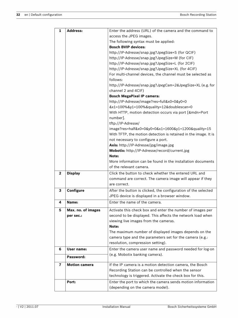
1 Address: Enter the address (URL) of the camera and the command to access the JPEG images.The following syntax must be applied:Bosch BVIP devices:http://IP-Adresse/snap.jpg?JpegSize=S (for QCIF)http://IP-Adresse/snap.jpg?JpegSize=M (for CIF)http://IP-Adresse/snap.jpg?JpegSize=L (for 2CIF)http://IP-Adresse/snap.jpg?JpegSize=XL (for 4CIF)For multi-channel devices, the channel must be selected as follows:http://IP-Adresse/snap.jpg?JpegCam=2&JpegSize=XL (e.g. for channel 2 and 4CIF)Bosch MegaPixel IP camera:http://IP-Adresse/image?res=full&x0=0&y0=0&x1=100%&y1=100%&quality=12&doublescan=0With HTTP, motion detection occurs via port [&mdn=Port number].tftp://IP-Adresse/image?res=half&x0=0&y0=0&x1=1600&y1=1200&quality=15With TFTP, the motion detection is retained in the image. It is not necessary to configure a port.Axis: http://IP-Adresse/jpg/image.jpgMobotix: http://IP-Adresse/record/current.jpgNote:More information can be found in the installation documents of the relevant camera.
2 Display Click the button to check whether the entered URL and command are correct. The camera image will appear if they are correct.
3 Configure After the button is clicked, the configuration of the selected JPEG device is displayed in a browser window.
4 Name: Enter the name of the camera.
5 Max. no. of images per sec.:
Activate this check box and enter the number of images per second to be displayed. This affects the network load when viewing live images from the cameras.Note:The maximum number of displayed images depends on the camera type and the parameters set for the camera (e.g.: resolution, compression setting).
6 User name: Enter the camera user name and password needed for log-on (e.g. Mobotix banking camera).
Password:
7 Motion camera If the IP camera is a motion detection camera, the Bosch Recording Station can be controlled when the sensor technology is triggered. Activate the check box for this.
Port: Enter the port to which the camera sends motion information (depending on the camera model).
Bosch Recording Station Default configuration | en 33
Bosch Sicherheitssysteme GmbH Installation Manual - | V2 | 2011.07
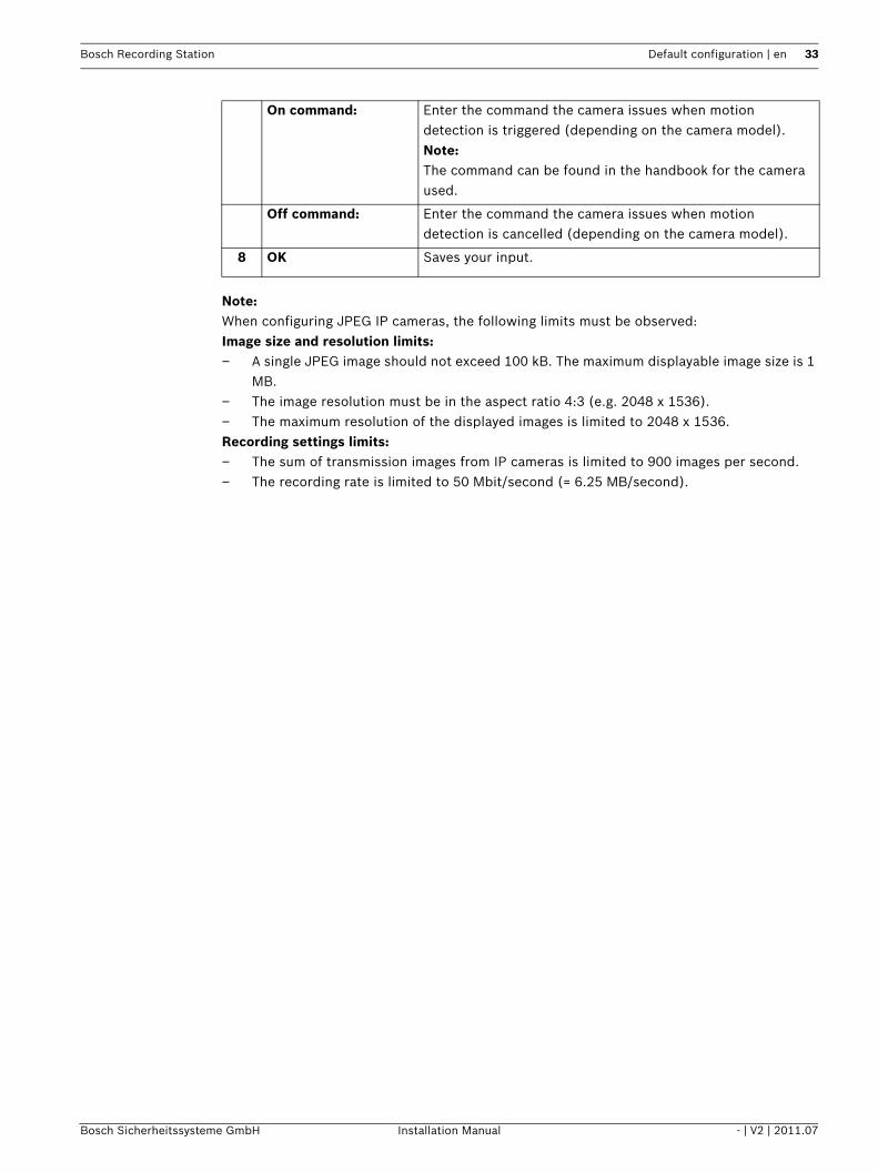
Note:When configuring JPEG IP cameras, the following limits must be observed:Image size and resolution limits:– A single JPEG image should not exceed 100 kB. The maximum displayable image size is 1
MB.– The image resolution must be in the aspect ratio 4:3 (e.g. 2048 x 1536).– The maximum resolution of the displayed images is limited to 2048 x 1536.Recording settings limits:– The sum of transmission images from IP cameras is limited to 900 images per second.– The recording rate is limited to 50 Mbit/second (= 6.25 MB/second).
On command: Enter the command the camera issues when motion detection is triggered (depending on the camera model).Note:The command can be found in the handbook for the camera used.
Off command: Enter the command the camera issues when motion detection is cancelled (depending on the camera model).
8 OK Saves your input.

34 en | Default configuration Bosch Recording Station
- | V2 | 2011.07 Installation Manual Bosch Sicherheitssysteme GmbH
4.3 Configuring Time ProfilesMenu Schedules
Assignment of the time profiles is done with the mouse cursor in a graphical time planner. There are 8 time profiles available. These time profiles can be assigned to any day of the week, individual holidays and special days. The time profiles are displayed in different colors.
1 WeekdaysSpecial daysHolidays
Click on the corresponding tab.Note:– You can select any day of the year in the tab labeled
Special days.– The Holidays tab is not displayed until the holiday file
Holidays.xml. has loaded.
2 Schedules Select the time period to which you want to assign a day. A time span can be assigned to only one time profile.
3 Graphical time planner Move the mouse cursor into the graphical time planner.Clicking with the left mouse button marks a cell. Dragging up a square while pressing the left mouse button marks a time profile. All selected cells take the color of the selected time profile. To edit selected cells in the graphical time planner, select another time profile and overwrite the cell already selected.
4 Rename schedule Changing the name. Select a schedule name and click on the button. Enter a new name and confirm the entry by pressing Enter.

Bosch Recording Station Default configuration | en 35
Bosch Sicherheitssysteme GmbH Installation Manual - | V2 | 2011.07
5 Holiday file - Load Loads the holiday file Holidays.xml. The holiday file contains state-specific holidays. The holiday file is editable and must be compiled individually for each state.In the tab labeled Holidays, click on Add and select the holidays.
6 Save Saves your input.

36 en | Default configuration Bosch Recording Station
- | V2 | 2011.07 Installation Manual Bosch Sicherheitssysteme GmbH
4.4 Configure Recording SettingsYou can configure the recording settings for MPEG4/H.264 IP cameras and JPEG IP cameras in this dialog box.
4.4.1 Configure Recording Settings for MPEG4/H.264 IP CamerasMenu Recording settings > Tab MPEG4/H.264 IP cameras
You can configure the recording settings for the MPEG4/H.264 IP camera in this dialog box.
1 Day - Night - Weekend ... All configured time profiles are displayed as tabs.Select the time profile for which the settings should apply.Note:The program only displays the time profiles that were configured in the Schedules menu.
2 MPEG/H.264 IP cameras Select the tab. The list field in the tab displays every MPEG4/H.264 IP camera.
3 In the camera list field Select the camera for which you want to edit the settings.Note:It is possible to select multiple cameras.
4 Pre-alarm recording Perform the settings for pre-alarm recording.
Stream: Select the stream for the MPEG4/H.264 device (Stream 1 or Stream 2).

Bosch Recording Station Default configuration | en 37
Bosch Sicherheitssysteme GmbH Installation Manual - | V2 | 2011.07
Audio:: Activate this check box if audio is also to be recorded.Note:Audio can only be selected if under IP cameras and encoders > MPEG4/H.264 IP cameras > Edit > General settings the Activate audio input check box is selected.
Pre-alarm time [secs.]: Select the pre-alarm time for the alarm and motion recording.Note:The maximum pre-alarm time is 1800 seconds. The pre-alarm time depends on the recording rate of the MPEG4/H.264 device's pre-alarm recording. A maximum of 3600 images can be recorded for each pre-alarm and by each camera.
5 Alarm recording Perform the settings for alarm recording.
Stream: Select the stream for the MPEG4/H.264 device (Stream 1 or Stream 2).
Audio: Activate this check box if audio is also to be recorded.
Post-alarm time [secs.]: Enter the post-alarm time.Note:The maximum post-alarm time is 999 seconds. The default setting is 0 seconds.
6 Continuous recording Perform the settings for continuous recording.
Stream: Select the stream for the MPEG4/H.264 device (Stream 1 or Stream 2).
Audio: Activate this check box if audio is also to be recorded.
7 Delete old video Activate this check box to automatically delete data after a specified number of days.
Older than [days]: Enter the number of days after which data should automatically be deleted.Example: 3 means that all data older than 3 days is automatically deleted.
Delete protected data Check box is activated: Protected data is automatically deleted after a specified number of days.Check box is not activated: Protected data is not automatically deleted.
8 Extended... Click on the button to process the alarm jobs for the selected camera.
9 Default settings Click the button to see the default settings.
10 Copy settings to other schedules...
Copies all tabs from the selected time profile with all the settings they contain into other time profiles.Click on the button. A dialog box opens where you can select the time profiles.
11 Save Saves your input.

38 en | Default configuration Bosch Recording Station
- | V2 | 2011.07 Installation Manual Bosch Sicherheitssysteme GmbH
4.4.2 Enhanced settings of the MPEG4/H.264 IP camerasMenu Recording settings > Tab MPEG4/H.264 IP cameras > Button Extended...
In this dialog box, you can change the settings for the alarm job.
1 Alarm jobs The list field shows all jobs where this camera is in the alarm recording list (in the Alarm processing menu).Note:The alarm jobs are added to the list field once the configuration has been saved.
2 Pre-alarm time [secs.]: Select the pre-alarm time for the alarm and motion recording.Note:The maximum pre-alarm time is 1800 seconds. The pre-alarm time depends on the recording rate of the pre-alarm recording. A maximum of 3600 images can be recorded for each pre-alarm and by each camera. Example: 1 image/second = 1800 seconds, 2 images/second = 1800 seconds, 4 images/second = 900 seconds, 5 images/second = 720 seconds etc.
3 Post-alarm time [secs.]: Enter the post-alarm time.Note:Make the settings for motion recording.
4 Audio: Activate this check box if audio is also to be recorded.

Bosch Recording Station Default configuration | en 39
Bosch Sicherheitssysteme GmbH Installation Manual - | V2 | 2011.07
4.4.3 Configure Recording Settings of JPEG IP CamerasMenu Recording settings > Tab JPEG IP cameras
You can configure the recording settings for the JPEG IP camera in this dialog box.
1 Day - Night - Weekend ... All configured time profiles are displayed as tabs.Select the tab you want to apply the settings to.Note:The program only displays the time profiles that were configured in the Schedules menu.
2 JPEG IP cameras Select the tab. All JPEG IP cameras are displayed in the list field underneath.
3 In the camera list field Select the camera for which you want to edit the settings.Note:It is possible to select multiple cameras.
4 Pre-alarm recording Perform the settings for pre-alarm recording.
Rate: Select the recording rate.Note:The actual recording rate depends on the camera type and the parameters set for the camera (e.g.: resolution, compression setting). The average setting is 4 - 6 images per second.

40 en | Default configuration Bosch Recording Station
- | V2 | 2011.07 Installation Manual Bosch Sicherheitssysteme GmbH
Pre-alarm time [secs.]: Select the pre-alarm time for the alarm and motion recording.Note:The maximum pre-alarm time is 1800 seconds. The pre-alarm time depends on the recording rate of the pre-alarm recording. A maximum of 3600 images can be recorded for each pre-alarm and by each camera.Example: 1 image/second = 1800 seconds, 2 images/second= 1800 seconds, 4 images/second = 900 seconds, 5 images/second = 720 seconds etc.
5 Alarm recording Perform the settings for alarm recording.
Rate: Select the recording rate.Note:The actual recording rate depends on the camera type and the parameters set for the camera (e.g.: resolution, compression setting).
Post-alarm time [secs.]: Enter the post-alarm time.Note:The maximum post-alarm time is 999 seconds. The default setting is 0 seconds.
6 Continuous recording Perform the settings for continuous recording.
Rate: Select the recording rate.Note:The actual recording rate depends on the camera type and the parameters set for the camera (e.g.: resolution, compression setting).
7 Delete old video Activate this check box to automatically delete data after a specified number of days.
Older than [days]: Enter the number of days after which data should automatically be deleted.Example: 3 means that all data older than 3 days is automatically deleted.
Delete protected data Check box is activated: Protected data is automatically deleted after a specified number of days.Check box is not activated: protected data is not automatically deleted.
8 Default settings Click the button to see the default settings.
9 Copy settings to other schedules...
Copies all tabs from the selected time profile with all the settings they contain into other time profiles.Click on the button. A dialog box opens where you can select the time profiles.
10 Save Saves your input.

Bosch Recording Station Default configuration | en 41
Bosch Sicherheitssysteme GmbH Installation Manual - | V2 | 2011.07
4.5 Configure Inputs and OutputsYou can configure the inputs and outputs in these dialog boxes.
4.5.1 Configure Alarm SimulationMenu Inputs and outputs > Tab Alarm simulation
You can configure 4 inputs for triggering user alarms on the user interface in this dialog box.
1 Alarm simulation Click on the tab.
2 Type Select whether or not an input should be activated.
Input is to be used for alarm simulation.
Input is not to be used for alarm simulation.
3 Name Enter the names.
4 Save Saves your input.

42 en | Default configuration Bosch Recording Station
- | V2 | 2011.07 Installation Manual Bosch Sicherheitssysteme GmbH
4.5.2 Configure Virtual InputsMenu Inputs and outputs > Tab Virtual inputs
Virtual inputs are inputs that are controlled via the browser interface or by a piece of software. They offer the same functionality as the other inputs in the system.The virtual inputs can be used to execute jobs, for example for alarm transmission or video export. There are 32 virtual inputs available.
Note:It is not necessary to log on to access the virtual inputs interface.
1 Virtual inputs Click on the tab.
2 Type Select whether or not a virtual input is to be configured.
Input is to be used as virtual input.
Input is not to be used as virtual input.
3 Name Enter the names.
4 Change field designator Click on the button. A dialog box opens. Edit the designation of the additional data as necessary.
5 Save Saves your input.

Bosch Recording Station Default configuration | en 43
Bosch Sicherheitssysteme GmbH Installation Manual - | V2 | 2011.07
4.5.3 Configure Automatic Teller MachinesMenu Inputs and outputs > Tab Automatic teller machine
You can connect a maximum of 4 automatic teller machines with two inputs each to the Bosch Recording Station.
1 Automatic teller machine Click on the tab.
2 Interface: Select the interface.
3 Status query [h]: After this time interval, the system checks repeatedly whether the connected automatic teller machines have completed a transaction. Enter the time in hours. Example: Entering 2 would mean that a check is run every 2 hours. Entering 0 would mean that no check is run.Note:If the system does not display a transaction, an error message is sent. If the connection between the Bosch Recording Station and the automatic teller machine is faulty, another error message is sent.
4 Type Select whether or not an input is to be configured.
The input is assessed.
The input is not assessed.

44 en | Default configuration Bosch Recording Station
- | V2 | 2011.07 Installation Manual Bosch Sicherheitssysteme GmbH
Assignment of inputs:Input 1 + 2 = automatic teller machine 1 Input 3 + 4 = automatic teller machine 2Input 5 + 6 = automatic teller machine 3Input 7 + 8 = automatic teller machine 4Inputs 1, 3, 5, 7 normally activate the portrait camera and inputs 2, 4, 6, 8 the cash dispenser camera.
5 Name Enter the names. The name can be freely selected.
6 Save Saves your input.

Bosch Recording Station Default configuration | en 45
Bosch Sicherheitssysteme GmbH Installation Manual - | V2 | 2011.07
4.5.4 Configure Foyer Card ReaderMenu Inputs and outputs > Tab Foyer card reader
You can connect a maximum of 4 foyer card readers to the Bosch Recording Station. Each foyer card reader uses one input. Anti-skimming is possible on the foyer card reader.
Note:You may not configure more foyer card readers than the number connected.
1 Foyer card reader Click on the tab.
2 Interface: Select the interface.
3 Type Select whether or not an input is to be configured.
A foyer card reader is connected to the input.
No foyer card reader is connected to the input.
4 Name Enter the names. The name can be freely selected.
5 Skimming protection This function recognizes whether there are any alien objects on the foyer card reader that may be able to read the data from an EC card without authorization.Note:– If this function is activated, the skimming input is
available as a trigger.– If anything triggers this, the event is recorded in
the logbook.– If the Show foyer card reader malfunction
function is also activated, a message appears in the user interface when a trigger is activated.

46 en | Default configuration Bosch Recording Station
- | V2 | 2011.07 Installation Manual Bosch Sicherheitssysteme GmbH
6 Time controlling - Setup Click the button if you want to enter a time control. A dialog box opens allowing you to select the default setting for the foyer card reader (open, automatic, closed) and the time profile (see also Section 4.5.5 Configure foyer card reader time control).
7 Locked out bank codes You have the possibility of locking out specific bank sort codes, i.e. the EC cards with the lock characteristics entered here do not have access authorization. Access is denied by the foyer card reader. The default setting of the foyer card reader must be set to: Foyer card reader automatic:
Add Enter the bank routing code to be locked into the text field and click on the button. After the entry, the bank routing code is held in the list field.Note:When making an entry, the use of wild cards (? or *) in any combination is allowed. ?: The exact position of the question mark may indicate any or no character.*: The exact position of the asterisk may indicate a sequence (one or more characters) of any or no characters (exception: * on its own means that all bank sort codes are locked out).
Delete Select the entry in the list field and click on the button. The bank routing code is deleted from the list field.
8 Show foyer card reader malfunction
A message is displayed in the user interface if there is a fault in the foyer card reader. If the Skimming protection function is also activated, a message also appears in the event of a skimming alarm.Note:If anything triggers this, the event is recorded in the logbook.
Ignore country code on EC cards
Does not analyze credit card data used to identify which country a card is from. Access is possible for cards with a different country code.
9 Save Saves your input.

Bosch Recording Station Default configuration | en 47
Bosch Sicherheitssysteme GmbH Installation Manual - | V2 | 2011.07
4.5.5 Configure foyer card reader time controlMenu Inputs and outputs > Tab Foyer card reader > Button Setup
Perform the settings for time control.
1 Foyer card reader time controlled
Activate the check box.
2 Default setting: Click the down arrow in the list field and select which default setting the foyer card reader should have.
3 In the previous point, you specified the default setting for the foyer card reader. If the default setting is to be limited in time, activate one or more of the following characteristics, as required.
Foyer card reader open:
Foyer always open.
Foyer card reader automatic:
Access is only possible with an EC card or a credit card. EC cards from specific banks can be locked out.
Foyer card reader closed:
Foyer always closed.
4 Schedule: Select the time profile within which the time limitation should apply (see also Section 4.3 Configuring Time Profiles).
5 OK Saves your input.

48 en | Default configuration Bosch Recording Station
- | V2 | 2011.07 Installation Manual Bosch Sicherheitssysteme GmbH
4.5.6 Configure Inputs from Alarm Panels (AP)Menu Inputs and outputs > Tab AP inputs
If an alarm panel is connected serially, a maximum of 32 inputs that can cause an alarm to be triggered in the system can be specified.As standard, every input has line statuses assigned that can be modified in LSN alarm panels for the specific project. In addition, alarm panel addresses can be assigned to each input.
1 AP inputs Click on the tab.
2 Connection settings
Interface: Select the interface.
Baud rate: Select the Baud rate.
Type: Select the alarm panel type.
3 Type Click the down arrow in the column and select the type of input.
The input type, e.g. holdup, is activated.
The input type is not activated.
Note:Each input has specific types of line statuses assigned as standard. This assignment can be changed for LSN alarm panels.
4 Name Enter the names.

Bosch Recording Station Default configuration | en 49
Bosch Sicherheitssysteme GmbH Installation Manual - | V2 | 2011.07
4.5.7 Assign Line Statuses to Inputs (Not for Bosch G Series)Menu Inputs and outputs > Tab AP inputs > Section Line status > Button Assign(see also Section 4.5.6 Configure Inputs from Alarm Panels (AP))
Assign alarm panel line statuses to the inputs.
Adding line statuses
Removing line statuses
5 Line status - Assign Click on the button. A dialog box opens allowing you to view and edit the default assignment of the line statuses (see also Section 4.5.7 Assign Line Statuses to Inputs (Not for Bosch G Series)).Note:Only possible for LSN alarm panels.
6 Addresses - Assign Click on the button. A dialog box opens allowing you to assign specific AP addresses to the input (see also Section 4.5.8 Assign Addresses to Inputs (Not for Bosch G Series) and Section 4.5.9 Assign Addresses to Inputs (Bosch G Series)).
7 Save Saves your input.
1 Unselected line statuses:
Select the line status.
2 << Add Click on the button. The line status is added to the Selected line statuses: list field.
5 Close Finishes the procedure. Saves the entries.
3 Selected line statuses:
Select the line status.
4 >> Remove Click on the button. The line status is removed from the Selected line statuses: list field.
5 Close Finishes the procedure. Saves the entries.

50 en | Default configuration Bosch Recording Station
- | V2 | 2011.07 Installation Manual Bosch Sicherheitssysteme GmbH
4.5.8 Assign Addresses to Inputs (Not for Bosch G Series)Menu Inputs and outputs > Tab AP inputs > Section Addresses > Button Assign(see also Section 4.5.6 Configure Inputs from Alarm Panels (AP))
Assign AP addresses (not Bosch G series) to the inputs.
Adding addresses
Removing addresses
1 Group:Alarm inputs:
Enter the starting address in the input fields.
2 Group:Alarm inputs:
Enter the final address in the input fields.
3 << Add Click on the button. The addresses are added to the Selected addresses: list field.
6 Close Finishes the procedure. Saves the entries.
4 Selected addresses: Select the addresses you wish to remove.
5 >> Remove Click on the button. The addresses are removed from the Selected addresses: list field.
6 Close Finishes the procedure. Saves the entries.

Bosch Recording Station Default configuration | en 51
Bosch Sicherheitssysteme GmbH Installation Manual - | V2 | 2011.07
4.5.9 Assign Addresses to Inputs (Bosch G Series)Menu Inputs and outputs > Tab AP inputs > Section Addresses > Button Assign (see also Section 4.5.6 Configure Inputs from Alarm Panels (AP))
Assign AP addresses for Bosch G series to the inputs.
1 AP addresses Activate the check boxes of the AP addresses you wish to assign to the input.
2 OK Saves your input.
52 en | Default configuration Bosch Recording Station
- | V2 | 2011.07 Installation Manual Bosch Sicherheitssysteme GmbH
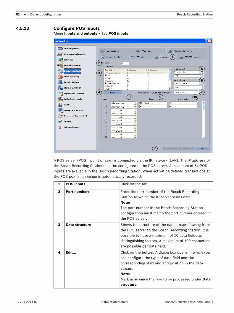
4.5.10 Configure POS InputsMenu Inputs and outputs > Tab POS inputs
A POS server (POS = point of sale) is connected via the IP network (LAN). The IP address of the Bosch Recording Station must be configured in the POS server. A maximum of 64 POS inputs are available in the Bosch Recording Station. When activating defined transactions at the POS points, an image is automatically recorded.
1 POS inputs Click on the tab.
2 Port number: Enter the port number of the Bosch Recording Station to which the IP server sends data.Note:The port number in the Bosch Recording Station configuration must match the port number entered in the POS server.
3 Data structure Shows the structure of the data stream flowing from the POS server to the Bosch Recording Station. It is possible to have a maximum of 10 data fields as distinguishing factors. A maximum of 100 characters are possible per data field.
4 Edit... Click on the button. A dialog box opens in which you can configure the type of data field and the corresponding start and end position in the data stream.Note:Mark in advance the row to be processed under Data structure.

Bosch Recording Station Default configuration | en 53
Bosch Sicherheitssysteme GmbH Installation Manual - | V2 | 2011.07
5 Switch on input Click on the arrow. The list of available data fields will be displayed. The list contains all data fields that are displayed under Data structure.Select the name of the data field and, in the text field underneath, enter the value that triggers an image recording in the data stream of the POS server. Where there are several values, these must be separated by semi-colons.
6 Switch off input Click on the arrow. The list of available data fields will be displayed.Select the name of the data field and, in the text field underneath, enter the value that ends an image recording in the data stream of the POS server. Where there are several values, these must be separated by semi-colons.
7 Data field with terminal number information:
Click on the arrow. The list of available data fields will be displayed.Select the name of the data field which describes the terminal number (e.g. cashpoint number).
8 Type Select whether or not an input should be activated.
Input should be used to trigger image recording.
Input should not be used to trigger image recording.
9 Name Place the cursor in the column and enter the name of the input.
10 Terminal number Enter the number of the terminal assigned to the POS input of the Bosch Recording Station.
11 Save Saves your input.

54 en | Default configuration Bosch Recording Station
- | V2 | 2011.07 Installation Manual Bosch Sicherheitssysteme GmbH
4.5.11 Configure ATM/POS InputsMenu Inputs and outputs > Tab ATM/POS - Inputs
The ATM/POS-Bridge is used to connect cashpoint systems and ATMs. A maximum of 8 ATM/POS-Bridges each with 4 automatic teller machines can be connected to the Bosch Recording Station. The video is connected via the IP network (LAN).
1 ATM/POS - Inputs Click on the tab.
2 Devices: Select the device.
3 IP address: Enter the IP address of the ATM/POS-Bridge.
4 Devices port number: Enter the port number of the ATM/POS-Bridge.
5 Port number: Enter the port number of the Bosch Recording Station.
6 Data structure: Shows the structure of the data stream flowing from the ATM/POS-Bridge to the Bosch Recording Station. It is possible to have a maximum of 10 data fields as distinguishing factors. The size of the data stream is limited to 7 kilobytes.Note:Each of the individual data fields can be activated by selecting the relevant check box. If none of the check boxes are selected, the entire data stream is written in the first data field.

Bosch Recording Station Default configuration | en 55
Bosch Sicherheitssysteme GmbH Installation Manual - | V2 | 2011.07
7 Edit... Click on the button. A dialog box opens in which you can configure the type of data field and the corresponding start and end position in the data stream.Note:Mark in advance the row to be processed under Data structure:.
8 Type Select whether or not an input should be activated.Note:Input 1 = ATM/POS device 1Input 2 = ATM/POS device 2Input 3 = ATM/POS device 3Input 4 = ATM/POS device 4
Input should be used to trigger image recording.
Input should not be used to trigger image recording.
9 Name Place the cursor in the column and enter the name of the input.Note:
10 Save Saves your input.

56 en | Default configuration Bosch Recording Station
- | V2 | 2011.07 Installation Manual Bosch Sicherheitssysteme GmbH
4.5.12 Configure I/O moduleMenu Inputs and outputs > I/O Module tab
A maximum of 8 I/O modules can be activated on a Bosch Recording Station. The following I/O modules can be activated:– ADAM-6017 (0 inputs, 2 relays)– ADAM-6018 (0 inputs, 8 relays)– ADAM-6022 (2 inputs, 2 relays)– ADAM-6024 (2 inputs, 2 relays)– ADAM-6050 (12 inputs, 6 relays)– ADAM-6050-W (12 inputs, 6 relays)– ADAM-6051 (12 inputs, 2 relays)– ADAM-6051-W (12 inputs, 2 relays)– ADAM-6052 (8 inputs, 8 relays)– ADAM-6055 (18 inputs, 0 relays)– ADAM-6060 (6 inputs, 6 relays)– ADAM-6060-W (6 inputs, 6 relays)– ADAM-6066 (6 inputs, 6 relays)
1 I/O module Click on the tab.
2 Devices: Select the I/O module.
3 IP address: Enter the IP address of the I/O module.
4 Device type: Select the type.
5 Type Select whether or not an input should be activated.
Input should be used to trigger image recording.
Input should not be used to trigger image recording.

Bosch Recording Station Default configuration | en 57
Bosch Sicherheitssysteme GmbH Installation Manual - | V2 | 2011.07
6 Name Enter the name of the input.
7 Type Select whether or not an input should be activated.
Relay should be used to trigger image recording.
Relay should not be used to trigger image recording.
8 Name Enter the name of the relay.
9 Save Saves your input.

58 en | Default configuration Bosch Recording Station
- | V2 | 2011.07 Installation Manual Bosch Sicherheitssysteme GmbH
4.6 Configure Alarm ProcessingMenu Alarm processing
In this dialog box you can specify so-called jobs for every time profile. Jobs are activities that are started by inputs and cameras with motion detection or a reference image check function.The following actions are possible:– Starting an alarm recording– Controlling a relay output– Controlling a maximum of four dome cameras and pan/tilt cameras– E-mail notification
1 Job
Add Adds a new job. The name of the new job is sequentially numbered and can be renamed.
Remove Removes a job. To do so, select the job.
Rename The name of the job can be changed. To do so, select the job.
2 Trigger In the list field, select the inputs or cameras with motion detection or a reference image check function whose triggering starts the job.The following are displayed as triggers:– All types of inputs– JPEG IP cameras and MPEG4/H.264 IP cameras with
motion detection/a reference image check function.– Skimming protection of foyer card reader
And All selected inputs and cameras must trigger in order to start the job.

Bosch Recording Station Default configuration | en 59
Bosch Sicherheitssysteme GmbH Installation Manual - | V2 | 2011.07
Or Only one input or one camera must trigger in order to start the job.
3 Day - Night - Weekend Select the time profile. The job is assigned to this time profile.Note:The program only displays the time profiles that were configured in the Schedules menu.Note:Using the Copy settings to other schedules... button, it is possible to copy jobs to other time profiles quickly.
4 Alarm recording list The inputs or cameras selected under Trigger trigger an alarm recording for the cameras named in the list.
Edit... Click on the button. A dialog box opens. Select the cameras for which alarm recording should take place.
Protect alarm recordings
Activate the check box. The alarm recordings are protected against overwriting (including pre-alarm images).Note:Protected data is only deleted after a certain number of days if in the Recording settings menu, the Delete old video and Delete protected data options are activated. It is also possible to manually delete in the user interface.
5 Relay control Specify the relay that is to be controlled.
Activate Activates the relay to be controlled.
Relay: Select the relay to be controlled.
Action: Select the relay behavior.Relay behavior:– Start of event: At the start of an event, the relay
switches for one second.– End of event: At the end of an event, the relay switches
for one second.– Follow event: The relay switches at the beginning of the
event, maintains this status during the event and returns to its original status at the end of the event.
– Follow recording: The relay switches at the start of the event and only returns to its original status after the end of alarm recording (including the post-alarm time).
6 Dome camera control A job can control a maximum of 4 dome cameras and pan/tilt cameras.Activate the check box of the line concerned. Then select the camera to be controlled in the list field and a saved position or a command.Note:Only different dome cameras and pan/tilt cameras can be controlled.The saved positions and commands must be configured under IP cameras and encoders > Camera Add / Edit > Dome settings.

60 en | Default configuration Bosch Recording Station
- | V2 | 2011.07 Installation Manual Bosch Sicherheitssysteme GmbH
7 E-mail notification Once a job has been triggered, a notification e-mail can be sent.
Activate Activates the e-mail notification.
Recipient: Enter the e-mail address of the recipient.Note:Where there are several e-mail addresses, these must be separated by semi-colons.
Configure E-mail... The e-mail server setup opens after the button is clicked. During setup, enter data on the transmitter name, e-mail address, user name etc.
8 Copy settings to other schedules...
Copies the selected job with all the settings it contains to other time profiles.Select a job and click the button. A dialog box opens where you can select the time profiles.
9 Save Saves your input.

Bosch Recording Station Default configuration | en 61
Bosch Sicherheitssysteme GmbH Installation Manual - | V2 | 2011.07
4.7 Configure the E-mail Server SetupMenu Alarm processing > Button Configure E-mail...orMenu Error forwarding and SNMP > Button E-mail server
E-mails can be sent regardless of whether or not you log on to the SMTP server.
Note:– For information on how to add an e-mail recipient for alarm processing, see
Section 4.6 Configure Alarm Processing– For information on how to add an e-mail recipient for error forwarding, see
Section 4.14.1 Adding a Recipient/Editing Recipient Data
1 Transmitter name: Enter the name of the sender. The name appears as the sender name for the e-mail recipient.
2 E-mail address: Enter the e-mail address of the sender.
3 SMTP server: Enter the name or the IP address of the SMTP servers (e-mail server).
4 SMTP-Port: Enter the number of the SMTP ports (standard value = 25).
5 With log-on to SMTP server
E-mails can only be sent when the sender is authorized to do so. The SMTP server checks the sender's authorization in this case.
6 User name: Enter the user name for logging on to the SMTP server.
7 Password: Enter the password for logging on to the SMTP server.
8 Save Saves your input.

62 en | Default configuration Bosch Recording Station
- | V2 | 2011.07 Installation Manual Bosch Sicherheitssysteme GmbH
4.8 Configure Remote StationsMenu Remote stations
In this dialog box, you determine the remote stations for your own workstation (local computer) so that you can connect to these remote stations later in the configuration process.
1 Local settings Edit the following settings for your own workstation.
Modem/ISDN: Select the modem or ISDN card.Note:To configure a modem connection, a RAS-capable modem must be connected and an RAS service installed.
Number of B channels Enter the number of B channels.
Accept incoming calls (for standard users)
Incoming calls may be accepted by standard users.
Password ... Enter the password that allows remote stations to be dialed into.
Info ... If no RAS capable modem is connected or RAS service installed, a notes icon and a button with additional information appears.
2 Remote stations You can create new remote stations here. Existing remote stations are displayed in the list field.Note: If the remote stations are configured to do so, theLow bandwidth column is also displayed in the list field.
New Creates a new remote station. Input your entries in the dialog box that opens.

Bosch Recording Station Default configuration | en 63
Bosch Sicherheitssysteme GmbH Installation Manual - | V2 | 2011.07
Edit Data on existing remote stations can be edited.Select the remote station from the overview in the lower part of the dialog box and click on the button.
Delete Deletes the connection to a remote station.Select the remote stations that you want to delete from the overview in the lower part of the dialog box and click on the button.
3 Save Saves your input.
64 en | Default configuration Bosch Recording Station
- | V2 | 2011.07 Installation Manual Bosch Sicherheitssysteme GmbH
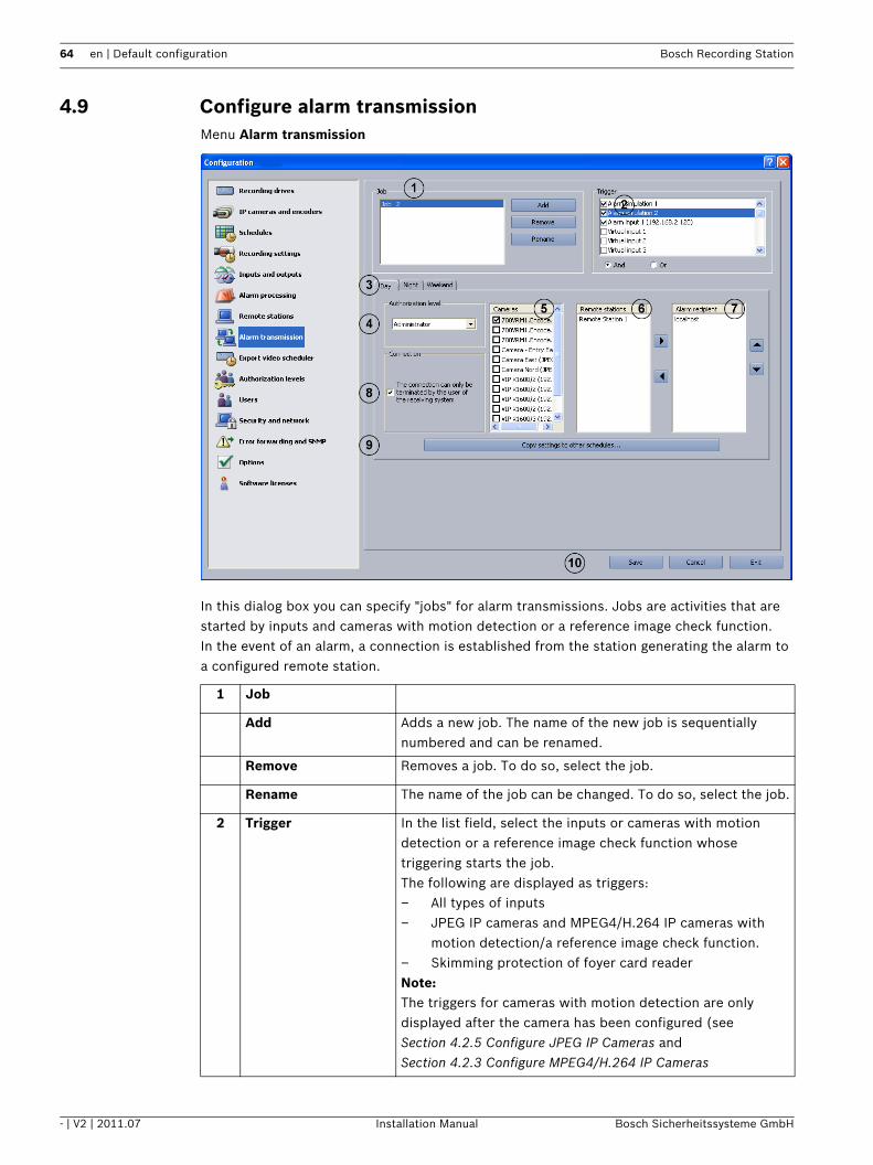
4.9 Configure alarm transmissionMenu Alarm transmission
In this dialog box you can specify "jobs" for alarm transmissions. Jobs are activities that are started by inputs and cameras with motion detection or a reference image check function.In the event of an alarm, a connection is established from the station generating the alarm to a configured remote station.
1 Job
Add Adds a new job. The name of the new job is sequentially numbered and can be renamed.
Remove Removes a job. To do so, select the job.
Rename The name of the job can be changed. To do so, select the job.
2 Trigger In the list field, select the inputs or cameras with motion detection or a reference image check function whose triggering starts the job.The following are displayed as triggers:– All types of inputs– JPEG IP cameras and MPEG4/H.264 IP cameras with
motion detection/a reference image check function.– Skimming protection of foyer card readerNote:The triggers for cameras with motion detection are only displayed after the camera has been configured (see Section 4.2.5 Configure JPEG IP Cameras and Section 4.2.3 Configure MPEG4/H.264 IP Cameras

Bosch Recording Station Default configuration | en 65
Bosch Sicherheitssysteme GmbH Installation Manual - | V2 | 2011.07
And All selected inputs and cameras must trigger in order to start the job.
Or Only one input or one camera must trigger in order to start the job.
3 Day - Night - Weekend Select the time profile. The job is assigned to this time profile.Note:The program only displays the time profiles that were configured in the Schedules menu.
4 Authorization level Select the authorization level.Note:The name of the authorization level and its connection password must match in the local station and in the remote station to which the alarm is transmitted. However, the individual enabling of authorization levels, for example enabled cameras, relays etc., may be different. Your remote station authorization level will be assigned to you when you dial in to the remote station.Activate the authorization to transfer alarms in the Authorization levels menu.
5 Cameras Select the cameras from which images are to be transmitted to the remote station.
6 Remote stations: The list field contains all remote stations known in the system.Select the remote station and, if necessary, one or more replacement remote stations to which the alarm is to be
transmitted and click on . The remote station is added to the Alarm recipient list field.
7 Alarm recipient The list field contains the remote stations to which an alarm transmission is to be made.Note:The remote stations to be called are worked through by the system from top to bottom. This means that the remote station to be dialed first must be at the top of the list. Replacement remote stations that are dialed into if a connection to the first remote station cannot be established
are listed beneath it. The sequence is specified with the
and buttons.
8 The connection can only be terminated by the user of the receiving system
Activate this check box if only the user of the receiving system is allowed to exit the connection.Otherwise, the connection will last as long as the event does.

66 en | Default configuration Bosch Recording Station
- | V2 | 2011.07 Installation Manual Bosch Sicherheitssysteme GmbH
Note:Multiple remote stations can be called up for one event. To do so, multiple jobs must be created.
9 Copy settings to other schedules...
Copies the selected job with all the settings it contains to other time profiles.Select a job and click the button. A dialog box opens where you can select the time profiles.
10 Save Saves your input.

Bosch Recording Station Default configuration | en 67
Bosch Sicherheitssysteme GmbH Installation Manual - | V2 | 2011.07
4.10 Configure Export Video SchedulerMenu Export video scheduler
In this dialog box you can specify "jobs" for the export video scheduler.
1 Job
Add Adds a new job. The name of the new job is sequentially numbered and can be renamed.
Copy An existing job is copied. To do so, select the job.
Remove Removes a job. To do so, select the job.
Rename The name of the job can be changed. To do so, select the job. The name must not contain any special characters.
2 Cameras Select the camera from which you want to export images.
3 Export video A maximum of 160 GB per day can be exported via a 1-gigabit network.The following requirements must be adhered to during the export process:– In live mode, no more than 16 cameras are displayed.– No search available in the database.– No playback of recorded images.
Number of days to be exported:
Enter the number of past days to be exported.

68 en | Default configuration Bosch Recording Station
- | V2 | 2011.07 Installation Manual Bosch Sicherheitssysteme GmbH
Examples of an export video schedulerThe examples show the export video time profile of the images.
Example 1:
Corresponding export video time profile:
Example 2:
Corresponding export video time profile:
Export current day Activate this check box if the current day is to be exported.Note:Images from the current day are only exported up to the point in time at which the job is executed. Images from the current day that have not yet been saved are not exported.
4 Day and time Select the days on which export video should be carried out.
Time: Enter the time for export video.
5 Target drive Select the target drive.
Browse... Opens a dialog box for selecting the target drive.
New network drive Adds a new network drive.
Disconnect network drive
Removes a network drive.
6 Save Saves your input.
Number of days to be exported:Export current daySunday
Time: 11:00:00 (= start of export video)
Thursday Friday Saturday Sunday00:00:00 11:00:00 start of export video procedure
Duration of the export video
Export video time profile of the images
End of the export video procedure and end of the exported data
Number of days to be exported:Export current daySunday
Time: 11:00:00 (= start of export video)
Thursday Friday Saturday Sunday00:00:00 11:00:00 start of the export video procedure
Duration of the export video
End of the export video procedure
Export video time profile of the images End of the exported data

Bosch Recording Station Default configuration | en 69
Bosch Sicherheitssysteme GmbH Installation Manual - | V2 | 2011.07
4.11 Create Authorization LevelsMenu Authorization levels
You can create different groups of authorizations in this menu if you have administrator rights. In these "authorization levels", you specify what authorizations the user has in the system.
1 New Creates a new authorization level.Click on the button and enter the name in the input field.Note:– The Administrator authorization level has complete
authorization within the system.– A user with the Extended authorization level may only
create users who have the same or lower authorization than a user with the authorization level Normal.
2 Delete Deletes an existing authorization level.
3 Connection password A dialog box opens after the button is clicked on. Enter the current connection password.Note:To establish a connection, the connection password must match that of the remote station.
4 Select user group... A dialog box opens. Select a user group for the LDAP server.Once you have confirmed your selection the user group (on the LDAP server) will be assigned to the authorization level in the Bosch Recording Station.See also Section 4.11.1 Select LDAP Server User Group.
70 en | Default configuration Bosch Recording Station
- | V2 | 2011.07 Installation Manual Bosch Sicherheitssysteme GmbH
5 Activate the check boxes of elements (cameras, relays) that should be available to users with this authorization level. For dome cameras and pan/tilt cameras, a second column with check boxes is displayed.Note:It is possible to select multiple elements. Then click on a check box. All check boxes in the relevant column are activated or deactivated.The check boxes in front of the elements mean:
: In live mode, only those cameras and relays are shown to the user that have the check box activated.
: In live mode, the user can only control those dome cameras and pan/tilt cameras with activated check boxes.Note:Bosch Recording Station only displays IP cameras that have already been configured. If new components are created, access to these by all access-authorized users must be configured retrospectively.
6 Select the access rights for the authorization level by activating the check box.Note:It is possible to select multiple elements. Then click on a check box. All check boxes in the relevant column are activated or deactivated.Here, the activated check boxes in front of the elements mean:
: In playback mode, only those cameras that have the check box activated are shown to the user.
: The saved images with additional data (e.g. date, time, ATM data) can be searched for, viewed, assessed, copied and printed out.
: The saved images from the corresponding camera can be deleted.
7 Configuration Determines the functions in the Bosch Recording Station configuration that members of this authorization level are permitted to carry out. Activate the check box next to the function in question.
8 Export video Allows users with this authorization level to export video images.Note:For the three pre-defined authorization levels, the exportation of video images cannot be deactivated.
9 Save Saves your input.

Bosch Recording Station Default configuration | en 71
Bosch Sicherheitssysteme GmbH Installation Manual - | V2 | 2011.07
4.11.1 Select LDAP Server User GroupMenu Authorization levels > Button Select user group...The use of LDAP (LDAP = Lightweight Directory Access Protocol) in conjunction with networked Bosch Recording Stations enables central information such as user groups, users, passwords, etc. to called up from one server for use in Bosch Recording Stations.The advantage of this is as follows:– Users available in the Bosch Recording Station network only need to be configured once
on the LDAP server, rather than on every Bosch Recording Station.– A user's authorization level can easily be changed by modifying the group association of
the user. Group association is only changed on the LDAP server.– It is only on the LDAP server that new users are added and previous users deleted.– Local users are also available. They will continue to be created on each system.Before you can make the settings below, the individual groups and their members have to be put on the LDAP server. These groups are then assigned to the authorization levels in the Bosch Recording Station. The configuration of the LDAP server is normally undertaken by the IT administrator, not the Bosch Recording Station administrator.You will require the assistance of your IT administrator to make the following entries.
Note:State each path as accurately as possible. This makes it quicker to search the LDAP server. The length of the search depends on the size of the database and can take several minutes.
LDAP server settings
1 LDAP server*: Name or IP address of the LDAP server.
2 Port*: Port number of LDAP server (default: unencrypted = 389; encrypted = 636)
3 Activate encryption For encrypted data transmission.

72 en | Default configuration Bosch Recording Station
- | V2 | 2011.07 Installation Manual Bosch Sicherheitssysteme GmbH
4 LDAP basis for users*: Unique name (DN = distinguished name) of LDAP path in which the search for the user should be performed.Example: Ask your IT administrator for the unique name (DN) of the LDAP basis.For example, you receive the following DN:CN=Users,DC=Security,DC=MyCompany,DC=com
5 Filter for users*: Filter for searching for unique user name.Ask your IT administrator for the filter to find a user with the user ID xy in the LDAP server.For example, for user xy you receive the following filter:(|(sAMAccountName=xy)(userPrincipleName=xy))Replace xy with %username% and enter the filter.
6 LDAP basis for groups*:
Unique name of LDAP path in which the search for groups should take place.
7 Filter for group members*:
Filter used to search for group members of a group.Example:Ask your IT administrator for the filter to find user xy with his DN (e.g. CN=xy,CN=Users,DC=Security,DC=MyCompany,DC=com) in the LDAP server. For example, you receive the following path:(&(objectclass=group)(member=DN).Replace DN with %usernameDN% and enter the path.
Proxy user
8 User name (DN*): Unique name of proxy user.
9 Password*: Proxy user password.
10 Testing Tests whether the proxy user has access to the LDAP server.
Test user authentication and group association
11 User name: User login ID, e.g. userB. The DN should not be entered here.
12 Password: User password.
13 Testing Tests whether the user ID and password are correct.
14 Group (DN): Unique group name. Used to check with which group the user is associated.
15 Testing Tests the group association of the user.
Selection of user group
16 Filter for groups: Filter for finding user groups.Ask your IT administrator for the filter to find the user group in the LDAP server.For example, you receive the following filter:(|(objectclass=group)(objectclass=groupofuniquenames))Enter the filter.

Bosch Recording Station Default configuration | en 73
Bosch Sicherheitssysteme GmbH Installation Manual - | V2 | 2011.07
17 Search user groups After you have clicked on it, all the user groups in the LDAP server that have the user as a member are searched.
18 existing user group: The user groups are displayed in the list field. Select the user group you require.
19 OK The user group will be saved in the Authorization levels menu.

74 en | Default configuration Bosch Recording Station
- | V2 | 2011.07 Installation Manual Bosch Sicherheitssysteme GmbH
4.12 Configure usersMenu Users
To protect access to system components and data, operations can only be carried out by users who are logged on. Every user is assigned an authorization level for work that he has to carry out (see also Section 4.11 Create Authorization Levels).Note:– An unlimited number of users can be created.– The user password only applies to the log-on procedure of a local user.– The Administrator authorization can only be issued by administrators.
NOTICE! The user with the Administrator authorization level must be protected with a password. Ensure that this password is only known to those persons who are responsible for this system.
1 New Creates a new user.Click New and enter a user name in the Name: input field.
2 Delete Deletes an existing user name.In the overview in the lower part of the dialog box, select the user name that you want to delete and click Delete.
3 Name: Name of the user. You can either enter a new user name here or change an existing one.
4 Password Click the button and enter a password for the user. Confirm your entries.
5 Authorization level: Click the down arrow in the list field and select an authorization level for the user.
Bosch Recording Station Default configuration | en 75
Bosch Sicherheitssysteme GmbH Installation Manual - | V2 | 2011.07
6 Dual authorization Activate this function if the user may only log on to the system together with another user.
7 Save Saves your input.

76 en | Default configuration Bosch Recording Station
- | V2 | 2011.07 Installation Manual Bosch Sicherheitssysteme GmbH
4.13 Configure Security and Network SettingsMenu Security and network
In this dialog box you can specify security settings, such as browser access and network connection encryption.
1 Security settings
Browser access without log-on permitted
Activate this check box if access to the system via a browser (without logging on) is to be permitted.Note:This function is only available for self-generated HTTP log-ons, not for standard log-ons.
Authorized user: Select the user in the list field whose authorization is to be used for the access.
All authorization levels may exit the video system
Activate this check box if all users are to receive authorization to exit the system.Note: The default setting allows only the administrator to exit the system.
Allow remote configuration
Allows the remote configuration of the Bosch Recording Station. Activate the check box for this.
2 Network adapter: Select the network adapter.
3 Transmission rate
Limit transmission rate
Activate this check box if you want to limit the transmission rate.
Transmission rate: Select the transmission rate for connections between Bosch Recording Station and Bosch Recording Station and Browser.

Bosch Recording Station Default configuration | en 77
Bosch Sicherheitssysteme GmbH Installation Manual - | V2 | 2011.07
Reception rate: Select the reception rate.
4 UDP tunneling (for firewall environments)
Enables a network connection between computers with Bosch Recording Stations via a single port.
Activate UDP tunneling
Activate this check box if you want to permit a network connection between Bosch Recording Stations via a fixed port.
Port number: Enter a port number that is not already used in the network. The port number on the Bosch Recording Station recorder and Bosch Recording Station receiver must be the same.Note:This port must be enabled in the network. The computer's Windows firewall must be deactivated.
Activate transmission encryption
Activate this check box if data transmission is to be encrypted.
Secret record: Enter a secret record of at least 10 digits. The secret record must be the same on both computers.
5 Save Saves your input.

78 en | Default configuration Bosch Recording Station
- | V2 | 2011.07 Installation Manual Bosch Sicherheitssysteme GmbH
4.14 Configure Error ForwardingMenu Error forwarding and SNMP
In the event of a malfunction, for example, external locations can be informed via network (= net send), SMS, e-mail or batch file. Error forwarding also applies to the malfunction relay.
1 Informing Specify the locations to be informed here.
Add Opens a dialog box. You can add a new recipient who will be informed in the event of a malfunction.Note: The computer name must not contain any special characters. The recipient's messenger service must be started up.
Edit Opens a dialog box. Data on existing recipients can be edited.Select the recipient in the overview and click on the button.
Remove An existing recipient can be removed from the list of those to be informed.Select the recipient in the overview and click on the button.
Testing Test the connection to the recipient.Select the recipient in the overview and click on the button.
2 Settings Perform the settings for the e-mail server and SMS service here.
E-mail server The e-mail server setup opens after the button is clicked. During setup, enter data on the transmitter name, e-mail address, user name etc.

Bosch Recording Station Default configuration | en 79
Bosch Sicherheitssysteme GmbH Installation Manual - | V2 | 2011.07
The following events lead to error forwarding:– The camera does not deliver a video signal– The logbook cannot be created or written– The images could not be recorded by the database server– Database server could not be started– Hard disk failure: X drive deactivated, all X drives deactivated– The hard disk is full (protected data)– Internal database error– Device could not be started– Export video scheduler error– Reference image check failed
4.14.1 Adding a Recipient/Editing Recipient DataMenu Error forwarding and SNMP > Button Add or Button EditHere you enter the recipient who is to be informed if malfunctions arise.
Notification via the network:
SMS service The SMS service configuration opens after the button is clicked. In the SMS configuration, enter data on the dialing parameters and modems, transmit options etc.
3 Malfunction relay Choose a relay that will forward error messages.
4 SNMP Bosch Recording Station sends camera, relay, input and database status messages to an SNMP (Simple Network Management Protocol) recipient via SNMP.See also Section 4.15.1 MIB List for SNMP and Section 4.15.2 Notification via SNMPNote:The option to send messages via relays, inputs and databases can be activated and deactivated. Camera messages cannot be deactivated.
Receiver 1: IP address or computer name of the 1st recipient.
Receiver 2: IP address or computer name of the 2nd recipient.
SNMP GET Port: Number of the port via which input, relay and camera statuses can be called up.
State message: Displays the statuses that trigger an SNMP message. Select the corresponding check box to activate.
5 Save Saves your input.
Transmission type: Select the transmission type Network (= net send).
Computer name/IP address
Enter the computer name or IP address of the recipient.Note:The computer name must not contain any special characters. The recipient's messenger service must be started up.
OK Saves your input.

80 en | Default configuration Bosch Recording Station
- | V2 | 2011.07 Installation Manual Bosch Sicherheitssysteme GmbH
Notification via e-mail:
Notification via SMS:
Notification via batch file:
Transmission type: Select the transmission type E-mail.
E-mail address Enter the e-mail address of the recipient.
OK Saves your input.
Transmission type: Select the transmission type SMS.
Telephone number Enter the telephone number of the recipient.
OK Saves your input.
Transmission type: Select the transmission type Batch file.
Batch file Enter the file name or click the adjacent button and select the file.
OK Saves your input.

Bosch Recording Station Default configuration | en 81
Bosch Sicherheitssysteme GmbH Installation Manual - | V2 | 2011.07
4.15 Configure OptionsMenu Options
In this dialog box you can edit optional settings, for example automatic disconnection, instant playback and acoustic signals.
1 Configuration data
Load A new configuration can be loaded. The new configuration overwrites the previous one.
Save The configuration can be saved on a network drive or a data carrier.Note:For security reasons, it is advisable to always save the configuration on an external data carrier.
2 Language Select the language of the Bosch Recording Station. Changes will not be applied until the Bosch Recording Station is rebooted.
3 Deactivate all views with more than 9 images windows
Deactivates all buttons with more than 9 image windows on the Bosch Recording Station user interface.
Deactivate all views with more than 4 image windows
Deactivates all buttons with more than 4 image windows on the Bosch Recording Station user interface.
4 Display image window with an aspect ratio of 16:9
Displays image windows in this aspect ratio in the user interface.

82 en | Default configuration Bosch Recording Station
- | V2 | 2011.07 Installation Manual Bosch Sicherheitssysteme GmbH
5 Displays name of the remote station in the title bar of the image window.
Displays the name of the remote station in the title bar of the image window.
6 Deactivate full-screen mode
Deactivates full screen mode on the Bosch Recording Station's user interface. This setting is useful if there is a touch screen, as depending on the model it may not be possible to return to full image mode.
7 Window of the Recording Station application can be minimized
Select this option if you want the user interface to be shrinkable. Changes will not be applied until the Bosch Recording Station is rebooted.
8 Hide virtual inputs Collapses virtual detectors in the user interface.
9 Rewind time for instant playback [seconds]
Enter the time here. A time between 2 seconds and 300 seconds can be selected.In Instant Playback, the images that have been saved in the selected camera are played back with a time delay after the live images. This means you will see the live image of the camera and the image of this camera from about 30 seconds ago. Playback is in real time.
10 Time until automatic log-off if the system is not in operation [in seconds]
Enter the time here after which automatic log-off should take place if there are no operations on the system.
11 Start Recording Station application with Windows session
Starts the application automatically when Windows is started.
12 Automatic disconnection
This function is used to automatically disconnect the local live image and all ISDN and network connections (previously connected independently by the Bosch Recording Station) after a specific time.
Time until display of warning dialog [seconds]
Enter the time after which a warning dialog is to be displayed.Note:The warning dialog allows you to either maintain the connection or break it immediately.
Time until disconnection if warning dialog remains unanswered [seconds]
Enter the time after which disconnection is to take place if the warning dialog remains unanswered (a value of 0 means that no disconnection will take place).
13 Alarm procedure in case of incoming alarm transmission
Specifies how incoming alarms are displayed in live or playback mode.
Display alarm cameras automatically in live mode
When in live mode this option lists the cameras and remote stations in alarm mode in the device list when alarm notification is received. The images are displayed automatically.

Bosch Recording Station Default configuration | en 83
Bosch Sicherheitssysteme GmbH Installation Manual - | V2 | 2011.07
additionally in playback mode
When in playback mode, the system switches to live mode if there is an alarm input. Cameras or remote stations in alarm status are listed in the device list. The images are displayed automatically.
Acoustic signal Assign an acoustic signal (wav file) to incoming video alarms. Enter the path and the file name or click Browse....
Playback Plays the acoustic signal.
Stop Ends playback of the acoustic signal.
Automatic alarm recording
Automatically records every incoming alarm on the Bosch Recording Station receiver.Note:The automatic alarm recording is displayed on the user interface.
Settings... Opens a dialog box. Configure more precise details on automatic alarm recording.See also Section 4.15.3 Configure Automatic Alarm Recording
13 Save Saves your input.
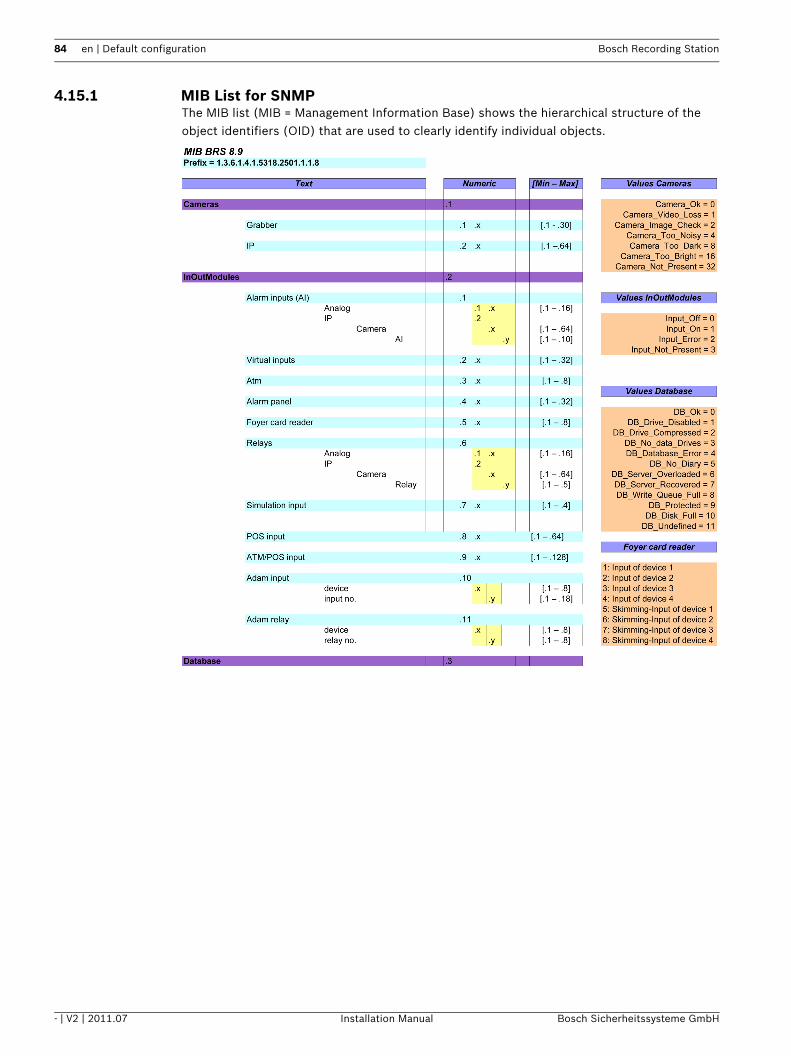
84 en | Default configuration Bosch Recording Station
- | V2 | 2011.07 Installation Manual Bosch Sicherheitssysteme GmbH
4.15.1 MIB List for SNMPThe MIB list (MIB = Management Information Base) shows the hierarchical structure of the object identifiers (OID) that are used to clearly identify individual objects.

Bosch Recording Station Default configuration | en 85
Bosch Sicherheitssysteme GmbH Installation Manual - | V2 | 2011.07
4.15.2 Notification via SNMPThe following events lead to notification:– The camera does not deliver a video signal– The logbook cannot be created or written– Database server could not be started– Hard disk failure: X drive deactivated, X drive not deactivated– The hard disk is full (protected data)– Internal database error– Live image and reference image differ– Image is noisy– Image too dark– Image too bright– Relay activated– Relay not activated– Internal malfunction or malfunction of external hard disks (e.g. malfunction relay has
triggered, hard disk is full)– Inputs activated (all Bosch Recording Station inputs)– Inputs deactivated (all inputs)
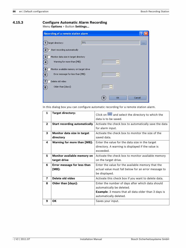
86 en | Default configuration Bosch Recording Station
- | V2 | 2011.07 Installation Manual Bosch Sicherheitssysteme GmbH
4.15.3 Configure Automatic Alarm RecordingMenu Options > Button Settings...
In this dialog box you can configure automatic recording for a remote station alarm.
1 Target directory:Click on and select the directory to which the data is to be saved.
2 Start recording automatically Activate the check box to automatically save the data for alarm input.
3 Monitor data size in target directory
Activate the check box to monitor the size of the saved data.
4 Warning for more than [MB]: Enter the value for the data size in the target directory. A warning is displayed if the value is exceeded.
5 Monitor available memory on target drive
Activate the check box to monitor available memory on the target drive.
6 Error message for less than [MB]:
Enter the value for the available memory that the actual value must fall below for an error message to be displayed.
7 Delete old video Activate this check box if you want to delete data.
8 Older than [days]: Enter the number of days after which data should automatically be deleted.Example: 3 means that all data older than 3 days is automatically deleted.
9 OK Saves your input.

Bosch Recording Station Default configuration | en 87
Bosch Sicherheitssysteme GmbH Installation Manual - | V2 | 2011.07
4.16 Activate Software LicensesMenu Software licenses
You can activate license packages in this dialog box. License packages are activated using a license activation key.
Note:Bosch Recording Station license packages are supplied together with an authorization letter or e-mail containing an authorization number. After the software is installed, they must be activated with a license activation key. See Section 4.16.1 Dialog box Activate license to find out how you can obtain these license activation keys.
1 License packages for activation
Select the license packages you want to activate.
2 Activate... Opens a dialog box. Enter the license activation code for the selected license package.
3 Activated packages The activated license package is displayed.
4 Enabled features Displays the activated features.
5 Save Saves your input.

88 en | Default configuration Bosch Recording Station
- | V2 | 2011.07 Installation Manual Bosch Sicherheitssysteme GmbH
4.16.1 Dialog box Activate licenseMenu Software licenses > Dialog box License activation > Select license > Button Activate...orConfiguration wizard > Dialog box License activation > Select license > Button Activate...
You can enter the license activation key in this dialog box in order to activate the license package.
Note:If your computer hardware does not provide a unique computer signature, you can purchase a dongle with a fixed dongle ID.Packages that already have a license must be transferred to the dongle ID. To do this, please contact Bosch Security Systems Technical Support.The dongle does not include the license itself. Activation with a license activation key is still required.
You have an authorization number and need a license activation key:1. Make a note of the computer signature or use the copy and paste function to insert it into
a text file.2. On a computer with Internet access, enter the following URL in the browser:
https://activation.boschsecurity.com
You are now in Bosch License Manager.
Follow the instructions to call up a license activation key. Make a note of the license activation key or use the copy and paste function to it into a text file.
3. In the Activate license dialog box in the Bosch Recording Station configuration, enter the license activation key called up from the Bosch License Manager and then click on Activate. The license package is activated.
Bosch Recording Station Default configuration | en 89
Bosch Sicherheitssysteme GmbH Installation Manual - | V2 | 2011.07
Note:Keep hold of the authorization number, computer signature and activation key in case you have any technical queries.

90 en | Remote Configuration Bosch Recording Station
- | V2 | 2011.07 Installation Manual Bosch Sicherheitssysteme GmbH
5 Remote ConfigurationYou can remotely configure a remote station via the user interface if it is named in the device list of the Bosch Recording Station.In contrast to the standard configuration, with remote configuration the following limitations apply:– Configuration of the Recording drives, Security and network and Software licenses
menus is not possible.– The option of creating network drives via the Export video scheduler menu is not
available. A target path can be selected.– The option of configuring the alarm procedure via the Options menu is not available.– It is not possible to display a live image in the configuration page of a BVIP device.
Note:Remote configuration of DiBos remote stations is not possible.
CAUTION! Ensure that a Bosch Recording Station device is not configured remotely if the local configuration is already open at the time. This procedure may lead to loss of data.

Bosch Recording Station Connections | en 91
Bosch Sicherheitssysteme GmbH Installation Manual - | V2 | 2011.07
6 Connections
6.1 Network Connection via DSL
The following example explains how the connection is set up:
Network connection between Bosch Recording Station recorder and Bosch Recording Station receiver via DSL
Bosch Recording Station recorderIn the configuration,1. In the configuration, select the Remote stations menu.2. Click New and enter the name of the remote station (Bosch Recording Station receiver).3. Enter the public address (Internet address) of the remote station's router (Bosch
Recording Station receiver), e.g. 193.252.10.5.4. Select Low bandwidth (live mode) if necessary.5. Click OK.6. In the configuration, select the Security and network menu.7. Select Activate UDP tunneling.8. Enter a free number (e.g. 1750) under Port number:.
Note:
Check that the port is unused using the netstat -a command.
9. Click on OK.Mapping IP addresses and computer names:1. Open the Notepad program.
To be carried out by authorized personnel only!
1 Bosch Recording Station recorder 4 Bosch Recording Station receiver
Computer name: BRS1 Computer name: Receiver1
IP address: 192.168.1.10 IP address: 192.168.0.2
Subnet mask: 255.255.255.0 Subnet mask: 255.255.255.0
2 UDP port: 1750 5 UDP port: 1750
3 DSL router 6 DSL router
Gateway:(Intranet address of router in the LAN)
192.168.1.1 Gateway:(Intranet address of router in the LAN)
192.168.0.254
Public address (Internet address) of router:
193.251.9.31 Public address (Internet address) of router:
193.252.10.5

92 en | Connections Bosch Recording Station
- | V2 | 2011.07 Installation Manual Bosch Sicherheitssysteme GmbH
2. Enter the public address (Internet address) of the remote station's router (Bosch Recording Station receiver) and the computer name of the remote station (Bosch Recording Station receiver). The address and the computer name must be separated by at least one space or tab character.
3. Save the file under the file name Imhosts in the directory C:\WINDOWS\system32\drivers\etc.
4. Remove the file extension .txt in Windows Explorer. The file must not have an extension.
5. Reboot the computer.In the router configuration:1. Use the standard configuration of the network provider.2. Activate the router's firewall.3. Activate port forwarding and forward the UDP port configured in the Bosch Recording
Station (e.g. 1750) to the IP address of the Bosch Recording Station recorder (e.g. 192.168.1.10). To do this, use the manufacturer's router documentation.
Note:DSL router and Bosch Recording Station recorder must be located in the same network.
Bosch Recording Station receiverIn the configuration of the receiver:1. In the configuration, select the Remote stations menu.2. Click New and enter the name of the remote station (Bosch Recording Station recorder).3. Enter the public address (Internet address) of the remote station's router (Bosch
Recording Station receiver), e.g. 193.251.9.31.4. Select Low bandwidth (live mode) if necessary.5. Click OK.6. In the configuration, select the Security and network menu.7. Select Activate UDP tunneling.8. Enter the port number that you have already used in the Bosch Recording Station
recorder (e.g. 1750) under Port number:.Note:
Check that the port is unused using the netstat -a command.
9. Click on OK.Mapping IP addresses and computer names:1. Open the Notepad program.2. Enter the public address (Internet address) of the remote station's router (Bosch
Recording Station receiver) and the computer name of the remote station (Bosch Recording Station recorder). The address and the computer name must be separated by at least one space or tab character.
3. Save the file under the file name lmhosts in the directory C:\WINDOWS\system32\drivers\etc.

Bosch Recording Station Connections | en 93
Bosch Sicherheitssysteme GmbH Installation Manual - | V2 | 2011.07
4. Remove the file extension .txt in Windows Explorer. The file must not have an extension.
5. Reboot the computer.In the router configuration:1. Use the standard configuration of the network provider.2. Activate the router's firewall.3. Activate port forwarding and forward the UDP port configured in the Bosch Recording
Station (e.g. 1750) to the IP address of the Bosch Recording Station recorder (e.g. 192.168.0.2). To do this, use the manufacturer's router documentation.
Note:DSL router and Bosch Recording Station receiver must be located in the same network.
Where there are several Bosch Recording Station recorders behind a DSL router
Note:If there are several Bosch Recording Station recorders behind the DSL router, it is recommended that you use a VPN (Virtual Private Network). You can obtain more detailed information regarding VPN settings from Bosch Security Systems.
6.2 Connecting External Hard Disks An SCSI controller must be installed in order to connect the external hard disk housing.External hard disks must be switched on before booting the PC.
CAUTION! Do not position the SCSI cable near to a power cable. This affects the transmission rate and may cause the connection to be interrupted.

94 en | Connections Bosch Recording Station
- | V2 | 2011.07 Installation Manual Bosch Sicherheitssysteme GmbH
6.3 Connecting an ATM (Serial)A maximum of four customer-operated ATMs or three customer-operated ATMs and one access control system can be connected to the Bosch Recording Station via an interface processor. The following ATM connection variants are possible:
Variant 1: Customer-operated automatic teller machines (ATMs) are located close to the Bosch Recording Station. The Bosch Recording Station and interface processor, as well as the interface processor and the ATMs, can be connected together in such a way that the distance between each of them is less than 15 m.Possible solution: Connection of each ATM is made directly at the interface processor and is ATM-specific. The distance between the Bosch Recording Station and the interface processor and the interface processor and the ATMs is no more than 15 m.Connection principle:
Connection details:
1 Bosch Recording Station 3 Interface processor
2 Max. 15 m 4 ATM1 - ATM4
1 Bosch Recording Station 4 Interface processor
2 COM x 5 ATM1 - ATM4
3 Connection cable, 9-pin
1
2
3
2
4
E4E3 PCE2E1
5
3 4
1
2

Bosch Recording Station Connections | en 95
Bosch Sicherheitssysteme GmbH Installation Manual - | V2 | 2011.07
Variant 2: Customer-operated automatic teller machines (ATMs) are located further away from the Bosch Recording Station. The Bosch Recording Station and interface processor and the interface processor and ATMs cannot be connected together in such a way that the distance between each of them is less than 15 m. The ATMs are, however, close enough together to allow them all to be connected to the interface processor in such a way that the distance between the interface processor and each ATM is less than 15 m. Possible solution:Connection of each ATM is made directly at the interface processor and is ATM-specific. You will need to install two OVS between the Bosch Recording Station and the interface processor to increase the range.Connection principle:
Connection details:
1 Bosch Recording Station 4 Max. 1000 m
2 Max. 15 m 5 Interface processor
3 OVS 6 ATM1 - ATM4
1 Bosch Recording Station 6 Max. 1000 m
2 COM x 7 OVS 2BR1 and BR2: position 2/3ST3: pin 2 = receive line, pin 3 = transmit line
3 9-pin 8 Interface processor
4 Connection cable, 9-pin, part no. 4.998.079.686 (1:1 connection)
9 to ATM1 - ATM4
5 OVS 1BR1 and BR2: position 1/2ST3: pin 2 = transmit line, pin 3 = receive line(By re-plugging the bridges BR1 and BR2 in the OVS, it is possible to swap over the transmit and receive lines.)
1 5
2
3
4 2
2
3 6
V24(ST3)
OPTO
1
5
9
6
OPTO
9
6
1
5
V24(ST3)
E4E3 PCE2E1
15
9
2
6
3
7
4
8
3
4

96 en | Connections Bosch Recording Station
- | V2 | 2011.07 Installation Manual Bosch Sicherheitssysteme GmbH
Variant 3:Customer-operated automatic teller machines (ATMs) are located further away from the Bosch Recording Station. The Bosch Recording Station and interface processor and the interface processor and ATMs cannot be connected together in such a way that the distance between each of them is less than 15 m. The individual ATMs are not close enough together to allow them all to be connected to the interface processor in such a way that the distance between the interface processor and each ATM is less than 15 m.Possible solution:The interface processor is connected directly to the Bosch Recording Station. To increase the range, two OVS are required between the interface processor and the ATM.Connection principle:
Connection details:
1 Bosch Recording Station 4 OVS
2 Max. 15 m 5 Max. 1000 m
3 Interface processor 6 ATM1 - ATM4
1 Interface processor 7 OVS 1BR1: position 1/2BR2: position 1/2ST3: pin 2 = transmit line, pin 3 = receive line
2 Connection cable for Bosch Recording Station (COM x)
8 Range max. 1000 m
3 As ATM1 9 OVS 2 (bridge setting depending on ATM)
4 To ATM2 - ATM4 10 ATM-specific cable connection or adapter
1
5
5
2
3
4
4
2
2
4
4
2
2
6
V24(ST3)
OPTO
1
5
9
6
OPTO
9
6
1
5
V24(ST3)
E4E3 PCE2E1
1
5
9
2
6
10
3
7
11
4
8
6

Bosch Recording Station Connections | en 97
Bosch Sicherheitssysteme GmbH Installation Manual - | V2 | 2011.07
5 Connection cable, 9-pin, part no. 4.998.079.686 (1:1 connection)
11 ATM1
6 9-pin
Note:By re-plugging the bridges BR1 and BR2 in the OVS, it is possible to swap over the transmit and receive lines.

98 en | Connections Bosch Recording Station
- | V2 | 2011.07 Installation Manual Bosch Sicherheitssysteme GmbH
6.4 Connecting an Alarm Panel
6.4.1 GeneralThe Bosch Recording Station is connected to an alarm panel (AP) via an RS232 interface on COM x, for example using an intermediate OVS interface converter.
Alarm-specific modifications to APs are not required when connecting them to the Bosch Recording Station (the required interface module must be present). All settings are made via the Bosch Recording Station user interface. The AP must have data transmission enabled and be fitted with an appropriate interface module (see relevant connection).Using the OVS assembly, any differing transmit and receive assignments on the devices for V.24 connection can be equalized out. Bridges BR1 and BR2 must be re-plugged.
1 Bosch Recording Station
2 COM x
3 RS 232 interface
4 OVS interface converter
5 Bosch AP
OPTOST3
1
52
3
4

Bosch Recording Station Connections | en 99
Bosch Sicherheitssysteme GmbH Installation Manual - | V2 | 2011.07
OVS interface converter bridge assignment
Exchanging transmit and receive lines – Variant 1:
BR1, BR2: position 1/2
ST3: pin 2 = transmit line, pin 3 = receive line
– Variant 2:BR1, BR2: position 2/3
ST3: pin 2 = receive line, pin 3 = transmit line
Note:For cabling, telephone cables of type J-Y(St)Y 2x2x0.6 are recommended. The cable shielding must be grounded at the alarm panel side to avoid earth currents.
1 OVS
2 12 V/24 V connection
Warning:Disconnect the mains plug before opening the OVS!
For 12 V/24 V supply
BR4: position 1/2
BR5: position 1/2
BR6: position 1/2
For 230 V supply
BR4: position 2/3
BR5: position 2/3
BR6: open
OPTO pin assignment V.24 (ST3) pin assignment
Direction Connection Direction Connection
Input - 1 Transmit/Receive * 2
Input + 6 Receive/Transmit * 3
Output + 5 0 V 5
Output - 9
* depending on BR1/BR2
OPTO V.24
ST3
BR2 BR1123
123
BR61
BR5321
BR4
ST11
2
321
−+
1
2

100 en | Connections Bosch Recording Station
- | V2 | 2011.07 Installation Manual Bosch Sicherheitssysteme GmbH
6.4.2 Connecting to NZ 500 (20 mA)
6.4.3 Connecting to BZ 500 (20 mA)
Only connect screening wire to NZ 500.Installation cable J-Y (St) Y 2x2x0.6
1 Bosch Recording Station 4 Range max. 1000 m
2 COM x 5 NZ 500
3 OVS 6 SU 500: (BR1 connected = 1200 bit/s)
Only connect screening wire to NZ 500.Installation cable J-Y (St) Y 2x2x0.6
COM 2 and COM 3 only with interface assembly ERSE 10
1 Bosch Recording Station 5 BZ 500 LSN
2 COM x 6 SM 20
3 OVS 7 ANNE 10
4 Range max. 1000 m 8 COM 1 to COM 3

Bosch Recording Station Connections | en 101
Bosch Sicherheitssysteme GmbH Installation Manual - | V2 | 2011.07
6.4.4 Connecting to AZ 1010/NZ 1008
V.24 connection to AZ 1010/NZ 1008
20 mA connection to AZ 1010/NZ 1008
Bridge assignment (V) on the SMAPlug-in bridge V1 in pos. 2/3Level for V.24 interface
Connection of the AZ 1010/NZ 1008 must be programmed on the alarm panel side.
1 Bosch Recording Station 4 AZ 1010/NZ 1008 (connection must be programmed on the alarm panel side)
2 COM x 5 SMA
3 Max. 25 m 6 SMA (plug-in bridge V1 in pos. 2/3, level for V.24 interface)
Bridge assignment (V) on the SMAPlug-in bridge V1 in pos. 1/2Level for V.24 interface
Only connect shielding wire to AZ 1010/NZ 1008. Cable J-Y (St) Y 2x2x0.6
1 Bosch Recording Station 4 Range max. 1000 m
2 COM x 6 GOM
3 OVS 7 LNA
5 AZ 1010/NZ 1008
SDI
0 V
SDO
2
3
5
S 3A S 3B
B2
B1 V1
123
1
5
2
6
3
4
SDI
SDO
+12V
SDI
SDO
ST3 OPTO
9
5
6
1
SDI
SDI+
SDO+
SDO
+UV
1 5
2
6
3 4

102 en | Connections Bosch Recording Station
- | V2 | 2011.07 Installation Manual Bosch Sicherheitssysteme GmbH
6.4.5 Connecting to NZ 1012
V.24 connection to NZ 1012
20 mA connection to NZ 1012
1 Bosch Recording Station 5 EAN
2 COM x 6 SSM
3 Max. 25 m 7 ZSN SW issues: 18508.0 A8.1, 18508.1 A8.1 4 NZ 1012
Dip-Fix assignment (S) and bridges (V) on the SSM
Interface 1: Interface 2:
S0 On: 1200 baud S4 On: 1200 baud
S1 Off: Bosch Recording Station
S5 Off: Bosch Recording Station
S2 On: Transmission priority for NZ 1012
S6 On: Device is connected
S3 On: Device is connected S7 On: Transmission priority for NZ 1012
V2, V4 Connected:
V.24 interface V12, V14 Connected:
V.24 interface
Note:It is possible to connect to interface 2.
1 Bosch Recording Station 5 NZ 1012 (insert SSM bridges at 20 mA)
2 COM x 6 GOM
3 OVS 7 EAN
4 Range max. 1000 m
S3S2
S0
V4
V2
SDI
0 V
SDO
3
2
5
1
5
2
6
3
7
4
ST3 OPTO
9
5
6
1
1
2
3 4
SDI
SDO
+U1
SDI
SDOSDI
SDI+
SDO+
SDO
+UV
5
6
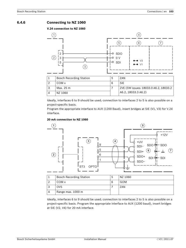
Bosch Recording Station Connections | en 103
Bosch Sicherheitssysteme GmbH Installation Manual - | V2 | 2011.07
6.4.6 Connecting to NZ 1060
V.24 connection to NZ 1060
Ideally, interfaces 6 to 9 should be used; connection to interfaces 2 to 5 is also possible on a project-specific basis.Program the appropriate interface to AUX (1200 Baud), insert bridges at SIE (V1, V3) for V.24 interface.
20 mA connection to NZ 1060
Ideally, interfaces 6 to 9 should be used; connection to interfaces 2 to 5 is also possible on a project-specific basis. Program the appropriate interface to AUX (1200 baud), insert bridges at SIE (V2, V4) for 20 mA interface.
1 Bosch Recording Station 5 ZAN
2 COM x 6 SIE
3 Max. 25 m 7 ZVE (SW issues: 18033.0 A6.2, 18033.2 A6.2, 18033.3 A6.2)4 NZ 1060
1 Bosch Recording Station 5 NZ 1060
2 COM x 6 GOM
3 OVS 7 ZAN
4 Range max. 1000 m

104 en | Connections Bosch Recording Station
- | V2 | 2011.07 Installation Manual Bosch Sicherheitssysteme GmbH
6.4.7 Connecting to UEZ 1000 (20 mA)
6.4.8 Connecting to UEZ 2000 (20 mA)
Only connect screening wire to UEZ 1000. Installation cable J-Y (St) Y 2x2x0.6
1 Bosch Recording Station 5 UEZ 1000
2 COM x 6 AVK
3 OVS 7 20 mA-1 to 20 mA-3
4 Range max. 1000 m
Only connect screening wire to UEZ 2000.Installation cable J-Y (St) Y 2x2x0.6
COM 4 and COM 5 only with interface assembly SEMO1
1 Bosch Recording Station 5 UEZ 2000 LSN
2 COM x 6 SM 20
3 OVS 7 AVM 100
4 Range max. 1000 m 8 COM 1 to COM 5

Bosch Recording Station Connections | en 105
Bosch Sicherheitssysteme GmbH Installation Manual - | V2 | 2011.07
6.4.9 Connecting to UGM 2020
20 mA connection to UGM 2020 via TESP (for telephony)
20 mA connection to UGM 2020 via UESS
1 Bosch Recording Station 5 UGM 2020
2 COM x 6 TESP (br. 1-4 open)
3 OVS 7 SGK (SW issues: SGKUGM)
4 Range max. 1000 m 8 EPC/EPC2 (from EAPS-4, EAPS-5)
1 Bosch Recording Station 5 UGM 2020
2 COM x 6 UESS (power surge protection)
3 OVS 7 SGK (SW issues: SGKUGM)
4 Range max. 1000 m 8 EPC/EPC2 (from EAPS-4, EAPS-5)

106 en | Troubleshooting and Checks Bosch Recording Station
- | V2 | 2011.07 Installation Manual Bosch Sicherheitssysteme GmbH
7 Troubleshooting and ChecksThis chapter outlines the causes of malfunctions that you may encounter when installing or operating the system. If you are unable to remedy the cause of a malfunction, please consult the manufacturer's product service video.
7.1 Troubleshooting
Malfunction Possible cause Solution
Device stops during the computer's boot phase.
Uninstall Bosch Recording Station and then reinstall the software.The Bosch Recording Station
application freezes.
There is a message stating that there are files on the drive that cannot be accessed.
There are corrupt sectors or corrupt files on the drives.
Use the Chkdsk program to check the drive where the operating system is located.To check drives containing image data start the AnalyzeDatabase.exe program.In both cases you should delete the files concerned. Also delete the directories in which the corrupt files are located.Note:A list of defective files is written to the log file of the DB server each time the Bosch Recording Station is started.
All cameras are crossed out. No video signal available. Check network connections.
Unlicensed. Initiate licensing process.
Network connection cannot be established and cameras are crossed out.
Computer name is assigned more than once.
Do not assign the computer name more than once.
IP address is incorrect. Enter correct IP address.
Firewall is activated. Deactivate the firewall or, if this is not possible, use UDP tunneling.
All AP inputs have been sounding for more than 10 seconds.
Interface error to AP. Remedy interface error.
Unlicensed. Initiate licensing process.
Camera video signal missing. No video signal available. Check video signal.
Images cannot be written. Images have been written to too many archives.
Modify recording.
Software feature not working.
Unlicensed. Initiate licensing process.Licensing is visible in the configuration.

Bosch Recording Station Troubleshooting and Checks | en 107
Bosch Sicherheitssysteme GmbH Installation Manual - | V2 | 2011.07
External hard disks are not recognized by the system.
Terminator missing. Plug in terminator.
Hard disk ID used twice. Set hard disk IDs in ascending order.
Disks are not formatted. Format hard disks for NTFS in hard disk manager.
No ISDN connection available.
Transmitter and receiver connection passwords do not match.
Check connection passwords.
Wrong protocol is set. Select appropriate protocol (EURO-ISDN) via an ISDN-PCI setup.
Malfunction Possible cause Solution

108 en | Troubleshooting and Checks Bosch Recording Station
- | V2 | 2011.07 Installation Manual Bosch Sicherheitssysteme GmbH
7.2 Checking the Network Connection Information on networking To install and test the network, you will require the following information from the network provider:– IP address– Subnet mask– (Gateway)
Notes on testing the networkTo install and test the network, use the following test program:1. Select Start -> All Programs -> Accessories -> Command Prompt.2. The commands available include:
ping
This command is only available if the TCP/IP protocol is installed.
ping localhost
This program checks the communication with the computer it is running on.
ping <Name of remote station> or ping <TCP/IP address of remote station>
The program checks communication with the remote station.
arp -a
The program displays other computers after making contact with them.
ipconfig
Shows all current TCP/IP network configuration values (IP address, subnet mask, default gateway)
tracert <name of remote station>
This program determines the path taken to a destination.
net view
Displays all available remote stations.
Note:Ping does not work if UDP tunneling is activated in the configuration.

Bosch Recording Station Troubleshooting and Checks | en 109
Bosch Sicherheitssysteme GmbH Installation Manual - | V2 | 2011.07
7.3 Checking the Optional ATM ConnectionThe data telegram between the Bosch Recording Station and the ATM can be checked using the HyperTerminal program in Windows® XP.– Start the program using the menu Start > All Programs > Accessories > Communications
> HyperTerminal.– When the program has started, enter a name (test name) in the dialog box and confirm
the entry.– In the following dialog box, select the interface to which the interface processor is
connected (Connect using input field). Confirm with OK.– Enter the following parameters:
- Bits per second: 9600 - Data bits: 8 - Parity: none - Stop bits: 1 - Flow control: none Confirm the entries with OK.
– In the File -> Properties -> Settings -> ASCII-Setup menu, activate the Append line feeds to incoming line ends check box. Confirm with OK.
The HyperTerminal configuration is finished. The data can now be evaluated.
Data telegram between Bosch Recording Station and interface processor:
Note:Action 1 = Card in ATM messageAction 2 = Hand to cash messageFor some ATMs, a message is generated as soon as the card is inserted, but does not display BRC or account number. For other ATMs, the message is first generated when the BRC and account number have been read and the PIN entry has been made correctly.
1 Card in ATM 8 Date
2 Card recognized by ATM 9 Time
3 Enter amount 10 Transaction number (Depends on ATM and computing center, not always available)
4 Hand to cash 11 Machine number
5 Removal of cash 12 Bank routing code
6 End of transaction 13 Account number
7 Interface number (0 - 3 for ATM1 - ATM4)
14 Amount
15 Camera number/action
1 280897 1318 08896
1 280897 1318 08896
1 280897 1318 08896
1 280897 1318 08896
1 280897 1318 08896
1 280897 1318 08896
82054135 0532037398 220
82054135 0532037398 220
82054135 0532037398 220 2
82054135 0532037398
1
82054135 0532037398 220
1
5
9 13
2
6
10 14
3
7 11 15
4
8 12

110 en | Troubleshooting and Checks Bosch Recording Station
- | V2 | 2011.07 Installation Manual Bosch Sicherheitssysteme GmbH
7.4 Installing a web serverInformation on installing a web server can be found in the installation handbook Installation of Web Server or der Security Knowledge Base database at the following link:http://knowledge.boschsecurity.com/.
7.5 Checking the Web Connection After activating the web application, check that you actually have access. Proceed as follows: 1. Start the web browser (Internet Explorer 6.x or higher). 2. In the browser, enter http://<hostname> under address. As <hostname>, specify either
the IP address or the name of the computer on which the web server is installed. The login screen of the Bosch Recording Station web application appears when a connection is installed. It is now possible to log on.
Bosch Recording Station Notes on Service and Maintenance | en 111
Bosch Sicherheitssysteme GmbH Installation Manual - | V2 | 2011.07
8 Notes on Service and Maintenance
8.1 Maintenance Work to be Carried OutPerform the following maintenance work:– On the system itself:
– Check that all cables are connected firmly– Check the fans and clean if necessary– Clean the screen if dirty– Check the system time and set if necessary
– Check the quality of the last five saved images per camera (e.g. sharpness, brightness, contrast).
– The images stored in the archives must be randomly checked (with regard to image quality and additional data).
– At least one trigger by a connected AP or a directly connected contact must be undertaken. The images placed in the archives as a result of this action must be checked and then deleted.
– The hard disk load must be checked. In agreement with the customer, it may be necessary to delete images.
– All freely accessible cameras and lenses as well as dome cameras and front screens of external cameras should be cleaned. While doing so, the connecting cables and connectors must be checked.
– The reference images printed or saved during installation of the system must be compared with the live images of the corresponding cameras with regard to their alignment. The customer is answerable to the administrative association (BGV) with regard to setting the image frame size.
– A functional test in accordance with UVV Kassen must be carried out at least once per month. The SP 9.7/7 Requirements for testing of optical room monitoring systems must be taken into account.
– Checking the customer's own printer (1 printout).– A test connection is to be set up for the ISDN connection. – For ATM connection:
– Check the connecting cables on the interface processor and on the OVS– Check the transmission of the transaction data– Access control data display (check the access control connection cable)
– All work carried out is to be documented in the operating handbook.
Maintenance work to be carried out by the operator The operator must:– Replace the toner cartridge for laser printers;– Replenish printer paper or the video printer paper cartridge, and– Replace the color cartridge for ink jet printers.
NOTICE! All work on the system that affects recording may only be carried out with the prior agreement of the customer. For UVV-relevant devices, it is preferable that this work is carried out outside of counter opening times.
112 en | Notes on Service and Maintenance Bosch Recording Station
- | V2 | 2011.07 Installation Manual Bosch Sicherheitssysteme GmbH
8.2 Software UpdateInstallation of the software is essentially carried out in the role of Windows Administrator.
8.3 Troubleshooting The following malfunctions are to be rectified as and when they occur:– Backlighting:
If backlighting effects are identified during recording, the light source must be covered up, for example using curtains over windows or lampshades on lighting; alternatively, the location of the camera should be changed.
– Reflections:If the optical room monitoring system is enclosed in bulletproof or toughened glass, the lighting conditions may cause reflections. These become stronger as the level of light within the glass enclosure increases. Such reflections can be reduced by increasing the illumination of the area outside the glass enclosure and positioning the cameras closer to the glass. Reflections can also often be avoided by covering light sources behind or next to the camera. If these measures do not help, a polarization filter can be fitted in front of the lens.
– Sharpness:When checking recordings, care should be taken that persons and objects are sharply delineated within the defined recording zone. To improve the image sharpness, "gray" or ND filters can be placed in front of the lens.
– Contamination:The quality of the recordings is frequently affected by dirt on the lens or the window of the security housing.
Errors or malfunctions can be fixed by 1. closing and re-establishing the local or remote connection;2. exiting the program and booting it again, or 3. warm starting or switching the system off and then on again (with a wait time of
approximately 20 seconds). If this does not restore normal operation, the configuration must be checked. If the malfunction cannot be fixed, the system must be replaced.
Bosch Recording Station Technical Specifications | en 113
Bosch Sicherheitssysteme GmbH Installation Manual - | V2 | 2011.07
9 Technical SpecificationsThe technical specifications can be found in the data sheet.
Bosch Recording Station Index | en 114
Bosch Sicherheitssysteme GmbH Installation Manual - | V2 | 2011.07
IndexAActivate licenses 87Add/change IP cameras 22Adding holidays 34Assign AP addresses (Bosch G Series) to inputs 51Assign AP addresses to inputs 50Assign AP line statuses to inputs 49Automatic alarm recording 81Automatic disconnection 81CConfigure alarm processing 58Configure alarm sequence 58Configure alarm simulation 41Configure alarm transmission 64Configure AP inputs 48Configure ATM/POS inputs 54Configure automatic recording for a remote station alarm 86Configure automatic teller machines 43Configure browser access 76Configure error forwarding 78Configure export video scheduler 67Configure foyer card reader 45Configure Foyer Card Reader Time Control 47Configure I/O module 56Configure JPEG IP cameras 31Configure MPEG4/H.264 IP cameras 26Configure options 81Configure POS inputs 52Configure Recording Drives 20Configure recording settings for MPEG4/H.264 IP cameras 36Configure recording settings of JPEG IP cameras 39Configure remote stations 62Configure the e-mail server setup 61Configure Users 74Configure virtual inputs 42Configuring dome/pan/tilt cameras 28Configuring SNMP 81Configuring time profiles 34Create authorization levels 69DDisconnection - Automatic 81Displaying alarm cameras 81EEdit MPEG4/H.264 IP cameras 24IInstant Playback 81IP cameras and encoders 22LLoad holidays file 34MMIB list 84MPEG4/H.264 Add IP cameras automatically 16, 23SSearch for IP cameras 22Search network 16, 23
Selecting LDAP server user groups 71Skimming protection 45Standard configuration
general 20UUDP tunneling 76

115 en | Index Bosch Recording Station
- | V2 | 2011.07 Installation Manual Bosch Sicherheitssysteme GmbH

116 en | Index Bosch Recording Station
- | V2 | 2011.08 Installation handbook Bosch Sicherheitssysteme GmbH

Bosch Sicherheitssysteme GmbHWerner-von-Siemens-Ring 1085630GrasbrunnGermanywww.boschsecurity.com© Bosch Sicherheitssysteme GmbH, 2011