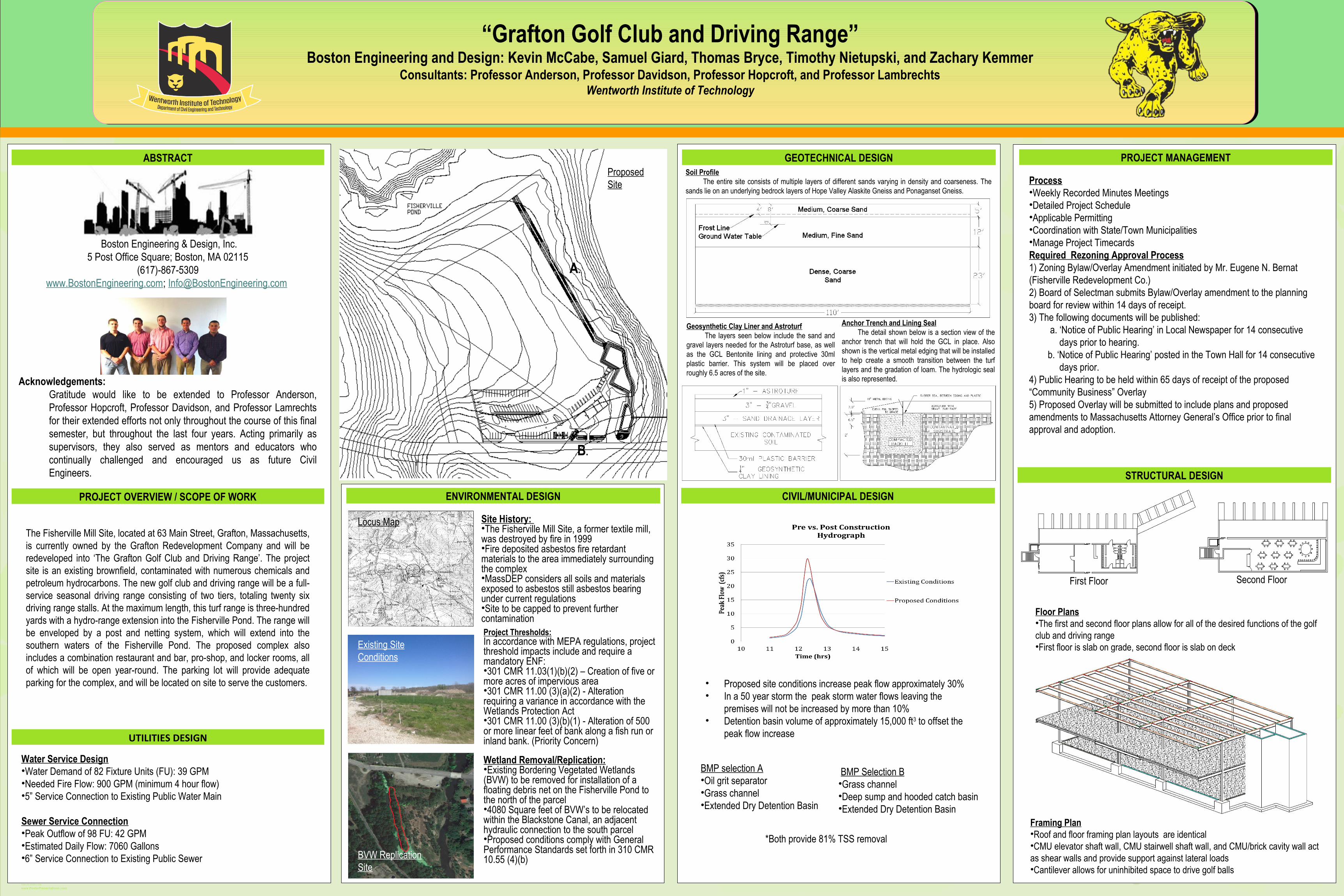
boston engineering and design poster

1
TEMPLATE DESIGN © 2008 www.PosterPresentations.com PROJECT OVERVIEW / SCOPE OF WORK STRUCTURAL DESIGN ENVIRONMENTAL DESIGN PROJECT MANAGEMENT The Fisherville Mill Site, located at 63 Main Street, Grafton, Massachusetts, is currently owned by the Grafton Redevelopment Company and will be redeveloped into ‘The Grafton Golf Club and Driving Range’. The project site is an existing brownfield, contaminated with numerous chemicals and petroleum hydrocarbons. The new golf club and driving range will be a full- service seasonal driving range consisting of two tiers, totaling twenty six driving range stalls. At the maximum length, this turf range is three-hundred yards with a hydro-range extension into the Fisherville Pond. The range will be enveloped by a post and netting system, which will extend into the southern waters of the Fisherville Pond. The proposed complex also includes a combination restaurant and bar, pro-shop, and locker rooms, all of which will be open year-round. The parking lot will provide adequate parking for the complex, and will be located on site to serve the customers. Site History: The Fisherville Mill Site, a former textile mill, was destroyed by fire in 1999 Fire deposited asbestos fire retardant materials to the area immediately surrounding the complex MassDEP considers all soils and materials exposed to asbestos still asbestos bearing under current regulations Site to be capped to prevent further contamination GEOTECHNICAL DESIGN CIVIL/MUNICIPAL DESIGN UTILITIES DESIGN “Grafton Golf Club and Driving Range” Boston Engineering and Design: Kevin McCabe, Samuel Giard, Thomas Bryce, Timothy Nietupski, and Zachary Kemmer Consultants: Professor Anderson, Professor Davidson, Professor Hopcroft, and Professor Lambrechts Wentworth Institute of Technology Boston Engineering & Design, Inc. 5 Post Office Square; Boston, MA 02115 (617)-867-5309 www.BostonEngineering.com ; [email protected] Acknowledgements: Gratitude would like to be extended to Professor Anderson, Professor Hopcroft, Professor Davidson, and Professor Lamrechts for their extended efforts not only throughout the course of this final semester, but throughout the last four years. Acting primarily as supervisors, they also served as mentors and educators who continually challenged and encouraged us as future Civil Engineers. Soil Profile The entire site consists of multiple layers of different sands varying in density and coarseness. The sands lie on an underlying bedrock layers of Hope Valley Alaskite Gneiss and Ponaganset Gneiss. Geosynthetic Clay Liner and Astroturf The layers seen below include the sand and gravel layers needed for the Astroturf base, as well as the GCL Bentonite lining and protective 30ml plastic barrier. This system will be placed over roughly 6.5 acres of the site. Anchor Trench and Lining Seal The detail shown below is a section view of the anchor trench that will hold the GCL in place. Also shown is the vertical metal edging that will be installed to help create a smooth transition between the turf layers and the gradation of loam. The hydrologic seal is also represented. Project Thresholds: In accordance with MEPA regulations, project threshold impacts include and require a mandatory ENF: 301 CMR 11.03(1)(b)(2) – Creation of five or more acres of impervious area 301 CMR 11.00 (3)(a)(2) - Alteration requiring a variance in accordance with the Wetlands Protection Act 301 CMR 11.00 (3)(b)(1) - Alteration of 500 or more linear feet of bank along a fish run or inland bank. (Priority Concern) Wetland Removal/Replication: Existing Bordering Vegetated Wetlands (BVW) to be removed for installation of a floating debris net on the Fisherville Pond to the north of the parcel 4080 Square feet of BVW’s to be relocated within the Blackstone Canal, an adjacent hydraulic connection to the south parcel Proposed conditions comply with General Performance Standards set forth in 310 CMR 10.55 (4)(b) Proposed site conditions increase peak flow approximately 30% In a 50 year storm the peak storm water flows leaving the premises will not be increased by more than 10% Detention basin volume of approximately 15,000 ft 3 to offset the peak flow increase BMP selection A Oil grit separator Grass channel Extended Dry Detention Basin Water Service Design Water Demand of 82 Fixture Units (FU): 39 GPM Needed Fire Flow: 900 GPM (minimum 4 hour flow) 5” Service Connection to Existing Public Water Main Sewer Service Connection Peak Outflow of 98 FU: 42 GPM Estimated Daily Flow: 7060 Gallons 6” Service Connection to Existing Public Sewer Process Weekly Recorded Minutes Meetings Detailed Project Schedule Applicable Permitting Coordination with State/Town Municipalities Manage Project Timecards Required Rezoning Approval Process 1) Zoning Bylaw/Overlay Amendment initiated by Mr. Eugene N. Bernat (Fisherville Redevelopment Co.) 2) Board of Selectman submits Bylaw/Overlay amendment to the planning board for review within 14 days of receipt. 3) The following documents will be published: a. ‘Notice of Public Hearing’ in Local Newspaper for 14 consecutive days prior to hearing. b. ‘Notice of Public Hearing’ posted in the Town Hall for 14 consecutive days prior. 4) Public Hearing to be held within 65 days of receipt of the proposed “Community Business” Overlay 5) Proposed Overlay will be submitted to include plans and proposed amendments to Massachusetts Attorney General’s Office prior to final approval and adoption. Floor Plans The first and second floor plans allow for all of the desired functions of the golf club and driving range First floor is slab on grade, second floor is slab on deck Framing Plan Roof and floor framing plan layouts are identical CMU elevator shaft wall, CMU stairwell shaft wall, and CMU/brick cavity wall act as shear walls and provide support against lateral loads Cantilever allows for uninhibited space to drive golf balls Existing Site Conditions ABSTRACT First Floor Second Floor BVW Replication Site Locus Map Proposed Site BMP Selection B Grass channel Deep sump and hooded catch basin Extended Dry Detention Basin *Both provide 81% TSS removal A. B.

Upload: thomas-bryce

Post on 22-Jan-2018

91 views

Category:

Documents


4 download

TRANSCRIPT

TEMPLATE DESIGN © 2008

www.PosterPresentations.com

PROJECT OVERVIEW / SCOPE OF WORK

STRUCTURAL DESIGN

ENVIRONMENTAL DESIGN

PROJECT MANAGEMENT

The Fisherville Mill Site, located at 63 Main Street, Grafton, Massachusetts, is currently owned by the Grafton Redevelopment Company and will be redeveloped into ‘The Grafton Golf Club and Driving Range’. The project site is an existing brownfield, contaminated with numerous chemicals and petroleum hydrocarbons. The new golf club and driving range will be a full-service seasonal driving range consisting of two tiers, totaling twenty six driving range stalls. At the maximum length, this turf range is three-hundred yards with a hydro-range extension into the Fisherville Pond. The range will be enveloped by a post and netting system, which will extend into the southern waters of the Fisherville Pond. The proposed complex also includes a combination restaurant and bar, pro-shop, and locker rooms, all of which will be open year-round. The parking lot will provide adequate parking for the complex, and will be located on site to serve the customers.

Site History: •The Fisherville Mill Site, a former textile mill, was destroyed by fire in 1999•Fire deposited asbestos fire retardant materials to the area immediately surrounding the complex•MassDEP considers all soils and materials exposed to asbestos still asbestos bearing under current regulations •Site to be capped to prevent further contamination

GEOTECHNICAL DESIGN

CIVIL/MUNICIPAL DESIGN

UTILITIES DESIGN

“Grafton Golf Club and Driving Range”Boston Engineering and Design: Kevin McCabe, Samuel Giard, Thomas Bryce, Timothy Nietupski, and Zachary Kemmer

Consultants: Professor Anderson, Professor Davidson, Professor Hopcroft, and Professor LambrechtsWentworth Institute of Technology

Boston Engineering & Design, Inc.5 Post Office Square; Boston, MA 02115

(617)-867-5309www.BostonEngineering.com; [email protected]

Acknowledgements:Gratitude would like to be extended to Professor Anderson, Professor Hopcroft, Professor Davidson, and Professor Lamrechts for their extended efforts not only throughout the course of this final semester, but throughout the last four years. Acting primarily as supervisors, they also served as mentors and educators who continually challenged and encouraged us as future Civil Engineers.

Soil Profile The entire site consists of multiple layers of different sands varying in density and coarseness. The sands lie on an underlying bedrock layers of Hope Valley Alaskite Gneiss and Ponaganset Gneiss.

Geosynthetic Clay Liner and Astroturf The layers seen below include the sand and gravel layers needed for the Astroturf base, as well as the GCL Bentonite lining and protective 30ml plastic barrier. This system will be placed over roughly 6.5 acres of the site.

Anchor Trench and Lining Seal The detail shown below is a section view of the anchor trench that will hold the GCL in place. Also shown is the vertical metal edging that will be installed to help create a smooth transition between the turf layers and the gradation of loam. The hydrologic seal is also represented.

Project Thresholds: In accordance with MEPA regulations, project threshold impacts include and require a mandatory ENF:•301 CMR 11.03(1)(b)(2) – Creation of five or more acres of impervious area •301 CMR 11.00 (3)(a)(2) - Alteration requiring a variance in accordance with the Wetlands Protection Act•301 CMR 11.00 (3)(b)(1) - Alteration of 500 or more linear feet of bank along a fish run or inland bank. (Priority Concern) Wetland Removal/Replication:•Existing Bordering Vegetated Wetlands (BVW) to be removed for installation of a floating debris net on the Fisherville Pond to the north of the parcel•4080 Square feet of BVW’s to be relocated within the Blackstone Canal, an adjacent hydraulic connection to the south parcel•Proposed conditions comply with General Performance Standards set forth in 310 CMR 10.55 (4)(b)

• Proposed site conditions increase peak flow approximately 30%• In a 50 year storm the peak storm water flows leaving the

premises will not be increased by more than 10%• Detention basin volume of approximately 15,000 ft3 to offset the

peak flow increase

BMP selection A•Oil grit separator•Grass channel•Extended Dry Detention Basin

Water Service Design•Water Demand of 82 Fixture Units (FU): 39 GPM•Needed Fire Flow: 900 GPM (minimum 4 hour flow)•5” Service Connection to Existing Public Water Main

Sewer Service Connection•Peak Outflow of 98 FU: 42 GPM•Estimated Daily Flow: 7060 Gallons•6” Service Connection to Existing Public Sewer

Process•Weekly Recorded Minutes Meetings•Detailed Project Schedule•Applicable Permitting •Coordination with State/Town Municipalities•Manage Project TimecardsRequired Rezoning Approval Process1) Zoning Bylaw/Overlay Amendment initiated by Mr. Eugene N. Bernat (Fisherville Redevelopment Co.)2) Board of Selectman submits Bylaw/Overlay amendment to the planning board for review within 14 days of receipt.3) The following documents will be published:

a. ‘Notice of Public Hearing’ in Local Newspaper for 14 consecutive days prior to hearing.

b. ‘Notice of Public Hearing’ posted in the Town Hall for 14 consecutive days prior.

4) Public Hearing to be held within 65 days of receipt of the proposed “Community Business” Overlay5) Proposed Overlay will be submitted to include plans and proposed amendments to Massachusetts Attorney General’s Office prior to final approval and adoption.

Floor Plans•The first and second floor plans allow for all of the desired functions of the golf club and driving range•First floor is slab on grade, second floor is slab on deck

Framing Plan•Roof and floor framing plan layouts are identical •CMU elevator shaft wall, CMU stairwell shaft wall, and CMU/brick cavity wall act as shear walls and provide support against lateral loads•Cantilever allows for uninhibited space to drive golf balls

Existing Site Conditions

ABSTRACT

First Floor Second Floor

BVW Replication Site

Locus Map

Proposed Site

BMP Selection B•Grass channel•Deep sump and hooded catch basin •Extended Dry Detention Basin

*Both provide 81% TSS removal

A.

B.