brief background - indiana
TRANSCRIPT

7/24/2012Indiana DOT Bridge Design Conference
AASHTO / NSBA Steel Bridge Collaboration
Guidelines for Design for Constructability
answers here…
Indiana DOT
Indianapolis, IN
July 24, 2012
William McEleneyNSBA, Director
Brief Background
• Consensus based
• AASHTO publication
7/24/2012Indiana DOT Bridge Design Conference
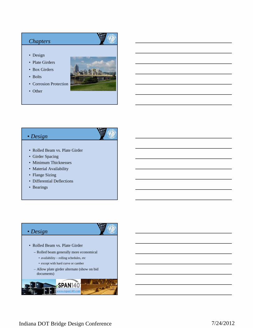
Chapters
• Design
• Plate Girders
• Box Girders
• Bolts
• Corrosion Protection
• Other
• Design
• Rolled Beam vs. Plate Girder
• Girder Spacing
• Minimum Thicknesses
• Material Availability
• Flange Sizing
• Differential Deflections
• Bearings
• Design
• Rolled Beam vs. Plate Girder
– Rolled beam generally more economical
• availability – rolling schedules, etc
• except with hard curve or camber
– Allow plate girder alternate (show on bid documents)
www.espan140.com
7/24/2012Indiana DOT Bridge Design Conference
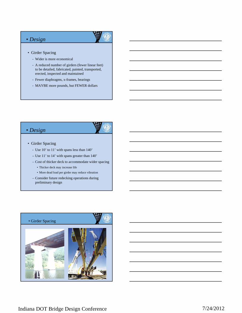
• Girder Spacing
- Wider is more economical
- A reduced number of girders (fewer linear feet) to be detailed, fabricated, painted, transported, erected, inspected and maintained
- Fewer diaphragms, x-frames, bearings
- MAYBE more pounds, but FEWER dollars
• Design
• Design
• Girder Spacing
- Use 10’ to 11’ with spans less than 140’
– Use 11’ to 14’ with spans greater than 140’
– Cost of thicker deck to accommodate wider spacing
• Thicker deck may increase life
• More dead load per girder may reduce vibration
– Consider future redecking operations during preliminary design
Design/Build
PENN DOT• Spans and approaches fixed
by 1st bridge (1973)
• Build ‘companion’ bridge (2000)
• WSD - 6 girder linesLFD - 4 girder lines
• Girder Spacing

7/24/2012Indiana DOT Bridge Design Conference
• Design
• Minimum Thicknesses
– Plate girder webs• 7/16” minimum, 1/2” preferred
– Plate girder flanges• 3/4” minimum
– Stiffeners, connection plates• 7/16” minimum, 1/2” preferred
• Plate Availability
–Arcelor-Mittal Steel USA• to 4” thick, 195” wide
–Nucor Steel• to 3” thick, 120” wide
–SSAB-IPSCO Steel• To 3” thick, 120” wide
–EVRAZ Claymont Steel• to 4” thick, 155” wide
• Design
• Plate size preferences - width
• Design
Modern Steel Construction, Sept 2011
• Plate size preferences – thickness increments

7/24/2012Indiana DOT Bridge Design Conference
• Wide Flange Beam Availability– NUCOR YAMATO - to 44” deep
– Gerdau Ameristeel - to 36” deep
– Steel Dynamics - to 36” deep
– 120’ long - max
– ASTM A992; ASTM A709, Gr. 50S• Minimum Yield = 50 ksi
• No HPS
• Design
Availability
• fabricator comments– rolled beam availability
– rolled beam vs. plate girder
– plate material availability
– other
• Plate Girder Flange Sizing
– Shop butt splices within a shipping piece – when to change area?
• No more than 2 shop slices
• Minimum change; 1/8” (to 2 ½” thick), 1/4”
• Maximum change; thinner piece at least 1/2 of thicker…
• ONLY when material cost saved > labor cost spent
• Design

7/24/2012Indiana DOT Bridge Design Conference
Weight Saving Factor Per Inch of Plate Widthfor ASTM A709-Gr 50 Non-Fracture Critical Flanges Requiring Zone 1 CVN Testing
Multiply weight savings/inch x flange width (length of butt weld)
Thinner Plateat Splice(inches)
Thicker Plate at Splice (inches)
1.0 1.5 2.0 2.5 3.0 3.5 4.0
1.0 70 70 70
1.5 80 80 80 80
2.0 90 90 90 70 70
2.5 100 100 80 80
3.0 110 90 90
3.5 110 110
4.0 130
• Flange Sizing – when to change area?
• Plate Girder Flange Sizing
– Shop butt splices within a shipping piece – what to change, width or thickness?
• Keep width constant (i.e., to change cross section area, change thickness)
• WHY ?
• compare changing width vs. changing thickness
• Design
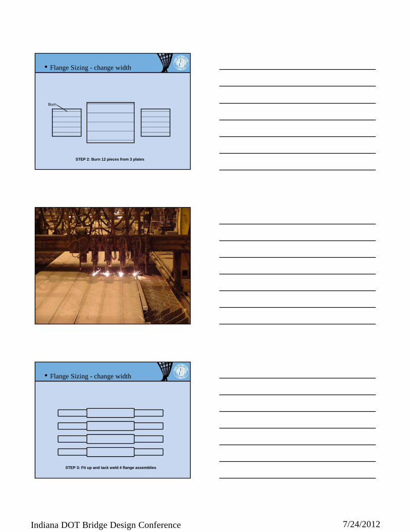
• Flange Sizing - change width
Bevel
STEP 1: Bevel (4) plate edges
FABRICATE 4 FLANGE ASSEMBLIES
7/24/2012Indiana DOT Bridge Design Conference
Burn
STEP 2: Burn 12 pieces from 3 plates
• Flange Sizing - change width
STEP 3: Fit up and tack weld 4 flange assemblies
• Flange Sizing - change width
7/24/2012Indiana DOT Bridge Design Conference
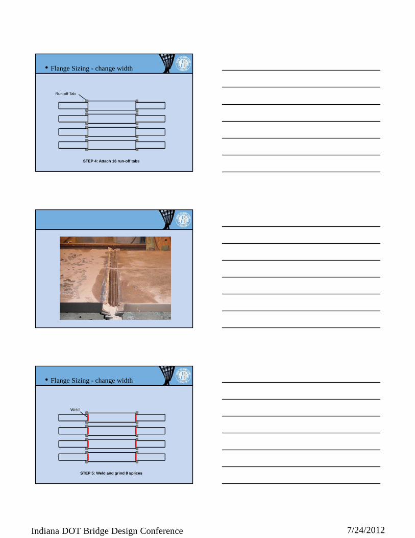
STEP 4: Attach 16 run-off tabs
Run-off Tab
• Flange Sizing - change width
STEP 5: Weld and grind 8 splices
Weld
• Flange Sizing - change width

7/24/2012Indiana DOT Bridge Design Conference
STEP 6: Turn over 4 flange assemblies
• Flange Sizing - change width
Weld
• Flange Sizing - change width
STEP 7: Back gouge, weld and grind 8 butt joints
STEP 8: Remove and grind 16 run-off tabs, taper wider plates
• Flange Sizing - change width
7/24/2012Indiana DOT Bridge Design Conference
Bevel
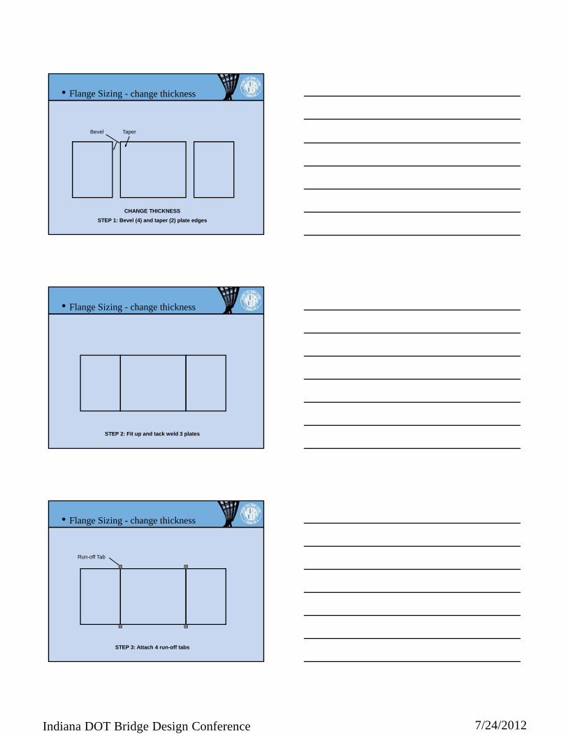
STEP 1: Bevel (4) and taper (2) plate edges
CHANGE THICKNESS
change thickness
Taper
• Flange Sizing -
STEP 2: Fit up and tack weld 3 plates
• Flange Sizing - change thickness
STEP 3: Attach 4 run-off tabs
Run-off Tab
• Flange Sizing - change thickness

7/24/2012Indiana DOT Bridge Design Conference
STEP 4: Weld and grind 2 splices
Weld
• Flange Sizing - change thickness
STEP 5: Turn over 1 piece
• Flange Sizing - change thickness
STEP 6: Back gouge, weld and grind 2 butt welds
Weld
• Flange Sizing - change thickness

7/24/2012Indiana DOT Bridge Design Conference
STEP 7: Remove and grind 4 run-off tabs
• Flange Sizing - change thickness
STEP 8: Burn 4 flanges from 1 assembly
Burn
• Flange Sizing - change thickness
STEP 8: Burn 4 flanges from 1 assembly
• Flange Sizing - change thickness

7/24/2012Indiana DOT Bridge Design Conference
• Flange Sizing
– Width transitions increase labor for flange assemblies up to 35%
– If you must change flange width, do so at bolted field splice (do not clip corners of top flanges)
– Allow fabricators to eliminate splices within a shipping piece by carrying thicker material through to next designed splice location
• Design
• Differential Dead Load Deflections
– Phased construction• omit crossframes between phases, if possible
• otherwise, single angle top & bottom strut (w/ 1 bolt)
– Curved girders• ‘beyond the scope’
– Skewed girders
• Design
• Skewed Girders

7/24/2012Indiana DOT Bridge Design Conference
STAGE 1
• Skewed Girders
1 1/2”
STAGE 2 STAGE 3 STAGE 4
• Skewed Girders
STAGE 5
• Skewed Girders
1
2
3

7/24/2012Indiana DOT Bridge Design Conference
STAGE 6
• Skewed Girders
STAGE 7
• Skewed Girders
• Design
• Bearings
– Use elastomeric if possible• 800 kips, 4” lateral, .04 radians rotation

7/24/2012Indiana DOT Bridge Design Conference
• Design
• Bearings
– Use pot bearing next
• Design
• Bearings
– Use elastomeric if possible• 800 kips, 4” lateral, .04 radians rotation
– Use pot bearing next
– See Collaboration G9.1, Steel Bridge Bearing Design and Detailing Guidelines
• Plate Girders
• Bearing Stiffeners/Diaphragms, Connection & Intermediate Stiffeners
• Welding
• General Details

7/24/2012Indiana DOT Bridge Design Conference
• Bearing Stiffeners/Diaphragms, Connection & Intermediate Stiffeners
– Bearing stiffeners can be either fabricated normal to top flange or vertical (plumb) under full dead load (DL) - effect on design is minimal
– Box girder bearing diaphragms can be either normal to top flange or vertical under DL
– Connection (and intermediate) stiffeners should be normal to top flange
• Plate Girders
• Bearing Stiffener Attachment
– mill to bear fit on bottom flange
• add a fillet weld (if transversely loaded)
- NO full penetration weld
- AWS D1.5 tolerances for fit between underside of bottom flange and bearing sole plate (projected area of bearing stiffeners and web)
• Plate Girders
• Bearing Stiffeners
7/24/2012Indiana DOT Bridge Design Conference
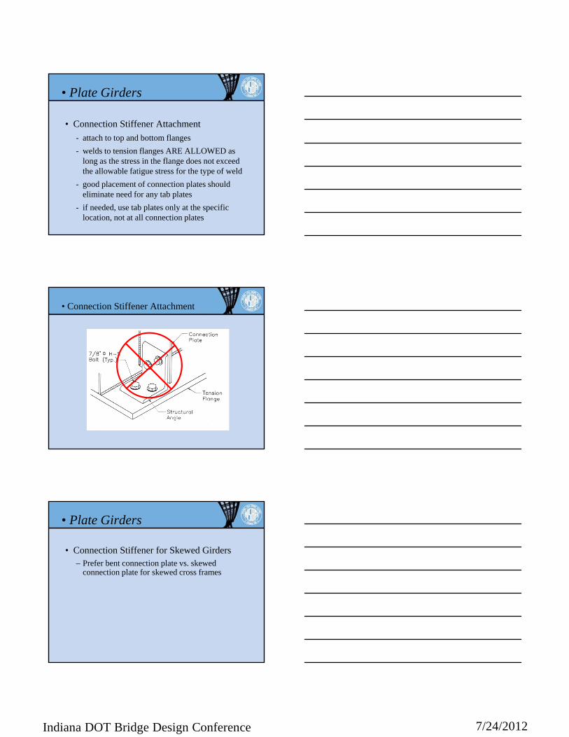
• Connection Stiffener Attachment
- attach to top and bottom flanges
- welds to tension flanges ARE ALLOWED as long as the stress in the flange does not exceed the allowable fatigue stress for the type of weld
- good placement of connection plates should eliminate need for any tab plates
- if needed, use tab plates only at the specific location, not at all connection plates
• Plate Girders
• Connection Stiffener Attachment
• Connection Stiffener for Skewed Girders– Prefer bent connection plate vs. skewed
connection plate for skewed cross frames
• Plate Girders

7/24/2012Indiana DOT Bridge Design Conference
• Skewed Cross Frame Connections
preferred (by fabricators)
20o maximum skew

7/24/2012Indiana DOT Bridge Design Conference
• Connection stiffener alternate for rolled beams– AASHTO
requirements revised in 2011 to allow ‘bolted clip angle’ for intermediate diaphragms – see 6.6.1.3.1
• Plate Girders (rolled beams)
• General Details– Intermediate Stiffeners – weld to compression
flange, tight fit (per AWS D1.5) to tension flange (not required, but may help fabricator to control flange tilt)
• Plate Girders
• General Details
– Shop Assembly Requirements
– Haunched Flange Transition• Bent or welded
• Straight or curved haunch
• Plate Girders
7/24/2012Indiana DOT Bridge Design Conference
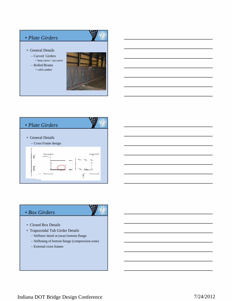
• General Details
– Curved Girders • heat curve / cut curve
– Rolled Beams• cold camber
• Plate Girders
• General Details
– Cross Frame design
• Plate Girders
• Closed Box Details
• Trapezoidal Tub Girder Details– Stiffener detail at (near) bottom flange
– Stiffening of bottom flange (compression zone)
– External cross frames
• Box Girders
7/24/2012Indiana DOT Bridge Design Conference
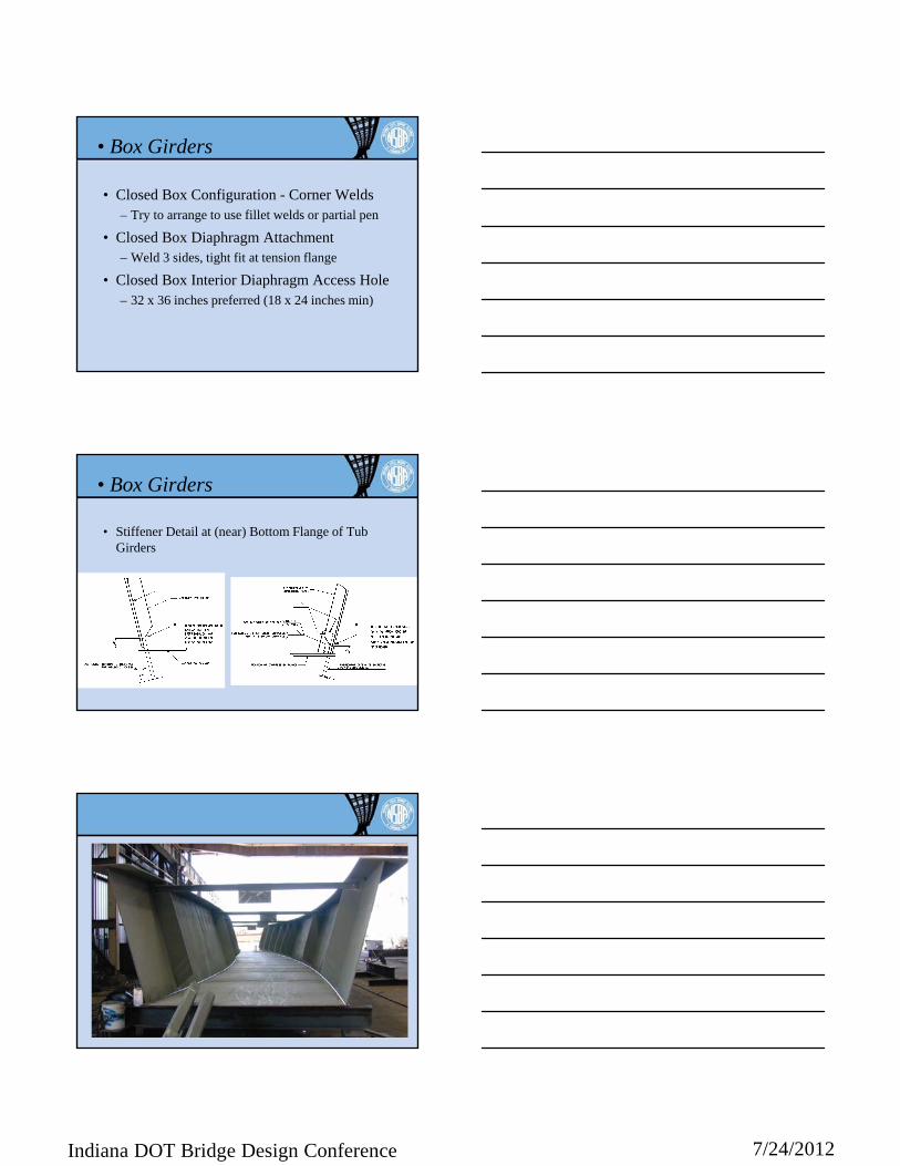
• Closed Box Configuration - Corner Welds– Try to arrange to use fillet welds or partial pen
• Closed Box Diaphragm Attachment– Weld 3 sides, tight fit at tension flange
• Closed Box Interior Diaphragm Access Hole– 32 x 36 inches preferred (18 x 24 inches min)
• Box Girders
• Stiffener Detail at (near) Bottom Flange of Tub Girders
• Box Girders

7/24/2012Indiana DOT Bridge Design Conference
• Stiffening of Bottom Flange (Compression Zone)– Use WTs (versus bars)
– Stop short of field splice (splice plates should adequately stiffen the flange)
• Box Girders
• Interior Coating– For inspection; single coat, light color
• Relative Costs of Closed Boxes and Tub Girders– No recommendation (box may be 20-30% more)
• External Cross Frames– At supports; for curved
• Box Girders
NSBA website• www.steelbridges.org

7/24/2012Indiana DOT Bridge Design Conference
Shipping/Fabrication Piece Limits
• To have the most competition:- Length < 125 feet
- Weight < 35 tons
- Height < 9 feet tall
• To ship, by road, max. fabricated segments:- Length < 175 feet (varies by state)
- Weight < 80 tons (varies by state)
- Height < 13.5 feet (on side) 9.5 feet (upright)
Collaboration Documents
NSBA website• www.steelbridges.org
AASHTO bookstore• www.transportation.org
SIMON
• Updating to 5th Edition AASHTO LRFD
• Enhanced with Graphic User Interface
• Distributed at WSBS in April – general distribution August 1
• www.steelbridges.org\softwareregistration

7/24/2012Indiana DOT Bridge Design Conference
NSBASplice
• Updated from AISI product (10 years ago) to 5th Edition AASHTO LRFD
• general distribution August 1
• www.steelbridges.org\softwareregistration
Contact Information…
• Bill [email protected]
• www.steelbridges.org