brief communication barc newsletteri issue no. 324 i jan. - feb. 2012 barc newsletter brief...
TRANSCRIPT


I ISSUE NO. 324 I JAN. - FEB. 2012
B A R C N E W S L E T T E RBRIEF COMMUNICATION
B A R C N E W S L E T T E R
ii I ISSUE NO. 325 I March - April 2012
In the Forthcoming issue
1. Early Detection of Coronary Heart Disease using
` Peripheral Pulse Analyzer
G.D. Jindal et al.
2. Development of Fluidized Bed Thermal Denitration
Neetu A. Baveja et al.
3. Passive Gamma Scanning: a Powerful Tool for
Quality Control of MOX Fuels
K.V. Vrinda Devi and J.P. Panakkal
4. MetProSoft-10: Image Analysis Software
for Metallographic Measurements
Lizy Pious et al.
5. Studies on Improvements in Thoria Dissolution Process
for Reprocessing Application
C. Srinivas et al.
6. Characterization of Deformation Microstructure
of TiAl alloys using Electron Microscopy
J.B. Singh et al.

ISSUE NO. 324 I JAN. - FEB. 2012 I
B A R C N E W S L E T T E R BRIEF COMMUNICATION
B A R C N E W S L E T T E R
ISSUE NO. 325 I March - April 2012 I I
C O N T E N T S
Editorial Note ii
Brief Communication
• Development of Peptide Mimic Shell Cross-linked Magnetic Nanocarriers for iii
Theragnostic Applications
• Photochemotherapy by Coralyne and UVA (CUVA): A Novel Strategy for Cancer Management iv
• Controlled Uptake and Release of Phototherapeutic Porphyrin Dye using Surface v
Functionalized Silver Nanoparticle Conjugates
• Designing Novel Nanomaterials for Application in Nuclear Waste Management vi
• Preparation and Characterization of (U0.47
,Pu0.53
)O2 Microspheres for Test Pin Irradiation in FBTR vii
• Hot Vacuum Extraction- Quadrupole Mass Spectrometry (HVE-QMS) for Ageing viii
Management of Zr-Nb Coolant Channels
Focus
• Frontiers in Science & Cutting Edge Technologies: Physics Group in BARC 1
S. Kailas
Research Articles
• Photocatalytic Hydrogen Generation from Water using Solar Radiation 10
R. Sasikala and S.R. Bharadwaj• Development of Carbon / Carbon Composites for Nuclear Reactor Applications 16
Ramani Venugopalan, D. Sathiyamoorthy and A.K. Tyagi
Technology Development Articles
• Development and Fabrication of LEU Plate Fuel for Modified Core of APSARA Reactor 21
G.J. Prasad, V.P. Sinha and P.V. Hegde
• Zinc Oxide Nanowires for Gas Sensing Application 28
Niranjan Ramgir, Niyanta Datta, Manmeet Kaur, S. Kailasaganapathi,A.K. Debnath, D.K. Aswal and S.K. Gupta
• Design and Application of a Formal Verification Tool for VHDL Designs 34
Ajith K. John, A.K. Bhattacharjee, Mukesh Sharma, G. Ganesh, S.D. Dhodapkar and B.B. Biswas
Feature Article
• Searching for the Proverbial Needle in a Haystack: the Information Dilemma 41
Sangeeta Deokattey and K. Bhanumurthy
News and Events
• Workshop on Photon and Ion Induced X-ray Emission Spectroscopy, PIXS 2012 47
• Workshop on Hadron Physics & India-PANDA Discussion Meeting: a report 48• DAE-BRNS Theme Meeting on Nuclear Reaction Data Evaluation: a report 49• 56th DAE Solid State Physics Symposium 2011: a report 50• Ninth Supervisory Training Programme on “Radioactive Waste Management” 51• School on Analytical Chemistry (SAC-2011): a report 53
• Report on DAE-BRNS National Workshop on Materials Chemistry (Functional Materials) 55
(NWMC 2011- FUNMAT)
• Status of Vitrification Technology for Treatment of High Level Liquid Waste: 56
Report of a Theme Meeting
BARC Scientists Honoured

I ISSUE NO. 324 I JAN. - FEB. 2012
B A R C N E W S L E T T E RBRIEF COMMUNICATION
B A R C N E W S L E T T E R
II I ISSUE NO. 325 I March - April 2012
From the Editor’s Desk
We are happy to bring you the second issue of this
year’s BARC Newsletter. We have been getting good response
to the feature “Brief Communication” introduced this year.
We invite all BARC Scientists and Engineers to contribute to
this feature and submit short one-page write-ups reporting the
latest Scientific/Technical developments carried out by them in
their respective areas of work. The proforma for submitting
these short articles is available at the SIRD Divisional website
under the hyperlink “Request Forms”.
This issue carries seven articles and also six Brief
Communications. The first article is from Dr. S. Kailas,
Director, Physics Group, which features a very interesting and
informative report of Physics research at BARC. The article
gives a broad overview of Basic research in Physics, design
and developmental activities relevant to the mandate of DAE
and National Facilities made available by the Physics Group for
R&D in various areas of Physics. One of the Research Articles
describes a method of Solar photocatalytic water splitting for
production of Hydrogen, the green energy source of the
future. The second Research Article focuses on the
development of Carbon-based materials used for nuclear
applications. Three Technology Development Articles and a
Feature Article are covered in this issue. We are sure this issue
will also provide enough reading material in diverse areas.
We will be shortly inviting all the DAE Award winners
for the year 2010, as well as other award winners for the year
2011, to submit their R&D contributions for the Founder’s
Day Special issue of the BARC Newsletter. It will be released in
October this year, on the occasion of Founder’s Day.
Dr. K. Bhanumurthy
On behalf of the Editorial Committee
Editorial Committee
Chairman
Dr. Tulsi Mukherjee,
Director, Chemistry Group
Vice Chairman
Dr. N. Ramamoorthy
Senior Advisor to Director, BARC
Edited by
Dr. K. Bhanumurthy
Head, SIRD
Associate Editors for this issue
Dr. A.K. Tyagi, ChD
Dr. S.K. Mukherjee, FCD
Members
Dr. Tulsi Mukherjee
Dr. N. Ramamoorthy
Mr. C.S.R. Prasad, ChTD
Dr. D.N. Badodkar, DRHR
Dr. A.P. Tiwari, RCnD
Dr. Madangopal Krishnan, MSD
Dr. A.K. Tyagi, ChD
Dr. P.V. Varde, RRSD
Dr. S.M. Yusuf, SSPD
Mr. Avaneesh Sharma, RED
Dr. C. Srinivas, PSDD
Dr. G. Rami Reddy, RSD
Dr. S.K. Mukherjee, FCD
Mr. G. Venugopala Rao, APPD
Dr. A. Vinod Kumar, EAD
Dr. Anand Ballal, MBD
Dr. K. Bhanumurthy, SIRD
Dr. S.C. Deokattey, SIRD

ISSUE NO. 324 I JAN. - FEB. 2012 I
B A R C N E W S L E T T E R BRIEF COMMUNICATION
B A R C N E W S L E T T E R BRIEF COMMUNICATION
ISSUE NO. 325 I March - April 2012 I III
Development of Peptide Mimic Shell Cross-linked
Magnetic Nanocarriers for Theragnostic
Applications
Chemistry Group
The combination of diagnosis and therapeutics
(theragnostic) allows a large degree of control over
the treatment of cancer. Magnetic nanoparticles
provide a unique platform for theragnostic
applications because of their biocompatibility,
magnetic resonance (MR) imaging capability, heating
ability under AC Magnetic Field (AMF), and their
sizes which are comparable to that of functional
biomolecules.
Water dispersible, pH responsive peptide mimic shell
cross-linked Fe3O
4 magnetic nanocarriers (PMNCs)
were developed by facile soft-chemical approach.
These nanocarriers are of an average size of about
10 nm, resistant to protein adsorption under
physiological medium and transform from a
negatively charged to a positively charged form in
an acidic environment. The terminal amino acid on
the shell of nanocarriers allows us to create
functionalized exteriors with high densities of
organic moieties (both amine and carboxyl) for
conjugation of drug molecules (Fig. 1 given below).
The drug-loading efficiency of the nanocarriers was
investigated using doxorubicin hydrochloride (DOX)
as a model drug to evaluate their potential as a
carrier system. Results showed high loading affinity
of nanocarriers for anticancer drug, their sustained
release profile, magnetic field induced heating and
substantial cellular internalization. The confocal
microscopy, flow cytometry and cell viability assay
demonstrate that use of these nanocarriers as
delivery vehicles could significantly enhance the
accumulation of drug in target cancer cells leading
to a high therapeutic efficacy which efficiently
inhibit their proliferation. Moreover, the enhanced
toxicity to tumor cells by DOX loaded PMNCs under
AMF suggest their potential for combination therapy
involving hyperthermia and chemotherapy. In
addition, these nanocarriers exhibit excellent T2 MR
contrast properties (r2 relaxivity: 217 mM-1s-1).
Specifically, the developed novel nanocarrier can
serve as base material for diagnosis as well as
therapy.
Fig.1: Peptide mimic shell cross-linked magnetic nanocarriers (PMNCs) and their drug targeting scheme, cellular
internalization (red fluorescence from DOX loaded PMNCs) and T2 weighted MR images

I ISSUE NO. 324 I JAN. - FEB. 2012
B A R C N E W S L E T T E RBRIEF COMMUNICATION
B A R C N E W S L E T T E RBRIEF COMMUNICATION
IV I ISSUE NO. 325 I March - April 2012
Photochemotherapy by Coralyne and UVA (CUVA):
A Novel Strategy for Cancer Management
Chemistry Group
Photodynamic therapy (PDT) is recognized as a
minimally invasive and non-toxic treatment strategy
for a wide range of medical conditions, including
cancers. However, PDT is useful only to treat
localized but not metastatic cancers. Instead,
photochemotherapy that combines the
chemotherapeutic and photosensitizing properties
of a drug might provide a promising modality in
cancer treatment. To this end, our group has recently
shown that a combination of the alkaloid, Coralyne
and UVA (CUVA) could dramatically enhance DNA
damage and a p53-independent apoptosis in
different cancer cells compared to coralyne alone.
The CUVA treatment showed superior efficacy over
the clinically-used Psoralene and UVA (PUVA)
treatment in inducing apoptosis in human breast
(MDA-MB-231 and MCF-7), skin (A431) and lung
(A549) carcinoma cell lines. Thus, the CUVA
treatment may represent a novel mechanism-based
protocol for management of a wide range of tumors.
Further, the ability of CUVA to sensitize cells
regardless of the p53 status may be of clinical
relevance given that approximately 50% tumors have
defects in the p53-dependent apoptotic pathway.
Superior efficacy of CUVA over PUVA in p53-independent PDT-
treatment clonogenic assay
Superior efficacy of CUVA over coralyne as
revealed by clonogenic assay
CUVA induces better DNA damage than coralyne as revealed by comet assay

ISSUE NO. 324 I JAN. - FEB. 2012 I
B A R C N E W S L E T T E R BRIEF COMMUNICATION
B A R C N E W S L E T T E R BRIEF COMMUNICATION
ISSUE NO. 325 I March - April 2012 I V
Controlled Uptake and Release of
Phototherapeutic Porphyrin Dye using
Surface Functionalized
Silver Nanoparticle Conjugates
Chemistry Group
Nanoparticles provide a versatile intermediate
between the molecular and macroscopic worlds.
Recently there has been a growing trend towards
making noble metal nanoparticle conjugates,
particularly of coin metals like gold, silver or
copper due to their extensive demand in molecular
plasmonic devices, biosensing, catalysis,
biomedical applications and so forth. Typically,
modulation of surface plasmon features has been
attempted by introducing modifiers or functional
units to construct tailor-made functional devices.
We report the synthesis of surface-functionalized
silver nanoparticle (AgNP) conjugates with
controlled size (5-30 nm) displaying different
characteristic colours based on supramolecular
approach involving macrocyclic host,
cucurbit[7]uril (CB7). These AgNP conjugates
(CB7-AgNP) display enhanced molecular
recognition features for the phototherapeutic
porphyrin dye, 5,10,15,20-tetrakis(4-N-
methylpyridyl)-porphyrin (TMPyP). The uptake and
release of TMPyP dyes with CB7-AgNP conjugates
by external stimuli like amantadine hydrochloride
has been demonstrated. Such supramolecular
engineering of nanoparticle conjugates suggests
prospective applications in biomedical sciences,
especially drug delivery mechanism and
therapeutic activation of drugs.
Fig. 1: Synthesis and characteristic colours of
silver nanoparticle conjugates
Fig. 2: Uptake & release mechanism

I ISSUE NO. 324 I JAN. - FEB. 2012
B A R C N E W S L E T T E RBRIEF COMMUNICATION
B A R C N E W S L E T T E RBRIEF COMMUNICATION
VI I ISSUE NO. 325 I March - April 2012
Designing Novel Nanomaterials for Application in
Nuclear Waste Management
Chemistry Group
Understanding the behavior of radioactive nuclide
elements in different environmental conditions is
an active area of research. We have investigated
the possible mechanism of interaction between
carbon nanotubes (CNT) and uranyl ion through
density functional theory based calculations. It is
shown that functionalized carbon nanotubes can
be used to bind uranyl ions much more efficiently
as compared to their unfunctionalized counterpart.
In this regard, we have considered various functional
groups such as carboxylic acids, oxo and
macrocycles. The uranyl binding energies are
sensitive to the nature of the functional groups rather
than the type of carbon nanotube. The binding takes
place preferably at the functionalized sites, although
pH could determine the strength of uranyl binding.
Our predicted results correlate well with the uranyl
sorption studies on CNT from experiments. Research
is in progress to find a suitable host molecule which
can bind actinyl cations selectively. These findings
are new and can open up a new era for actinide
speciation and separation chemistry using
functionalized carbon nanotubes.
Fig. 1: Optimized structure of functionalized CNT
encapsulating a uranyl ion.
Fig. 2: Optimized structure of binding of uranyl ion
at the functionalized CNT site.

ISSUE NO. 324 I JAN. - FEB. 2012 I
B A R C N E W S L E T T E R BRIEF COMMUNICATION
B A R C N E W S L E T T E R BRIEF COMMUNICATION
ISSUE NO. 325 I March - April 2012 I VII
Preparation and Characterization of (U0.47
,Pu0.53
)O2
Microspheres for Test Pin Irradiation in FBTR
Radiochemistry and Isotope Group
Conventionally ceramic nuclear fuels are prepared
in the form of cylindrical pellets by ‘powder-pellet’
route having several process steps e.g., milling,
granulation, power compaction, etc. and is
associated with radiotoxic dust hazard. On the other
hand Sol-Gel process, being a wet chemical route,
is dust-free, minimizes the problems of radioactive
aerosols and is ideally suited to remote and
automated manufacturing of highly radiotoxic
plutonium and 233U bearing mixed oxide fuels.
Vibro-compacted sphere-pac fuel pin is one of the
methods for loading sol-gel derived fuel particles in
a clad tube. The fuel is in the form of small spheres,
normally in two or three different size fractions.
Apart from the advantages during fabrication,
sphere-pac fuel has exhibited comparable if not
better performance during irradiation. In view of
various positive aspects associated with sol-gel
derived sphere-pac fuel and need of our own
irradiation data, the task force on sol-gel vibro
compaction technology, comprising scientists from
BARC and IGCAR, has proposed to irradiate a capsule
containing two sphere-pac pins and a reference pin
with solid pellets in FBTR for 300 h. MOX fuel
microspheres of 780 μm size containing
53 % PuO2 prepared at BARC and natural UO
2
microspheres of 115 μm size are vibro compacted
in the ratio 3:1 to achieve a smear density of 80 %
TD. This is to be irradiated initially for 100 h at 205
W/cm and then for 200 h at 260 W/cm peak power.
The internal gelation process, which was originally
developed at the KEMA labs Netherlands, was
significantly modified to prepare high density MOX
microspheres containing such high concentration
of Pu for the first time. About 72 g of characterized
MOX microspheres were sent to IGCAR for sphere-
pac fuel pin fabrication and irradiation.
Fig. 1: (a) Sintered (U0.47
,Pu0.53
)O2 Microspheres for Sphere-pac Fuel Pin fabrication
(b) Auto α Radiography of MOX microspheres Exhibiting Uniform Distribution of Pu

I ISSUE NO. 324 I JAN. - FEB. 2012
B A R C N E W S L E T T E RBRIEF COMMUNICATION
B A R C N E W S L E T T E RBRIEF COMMUNICATION
VIII I ISSUE NO. 325 I March - April 2012
Hot Vacuum Extraction- Quadrupole MassSpectrometry (HVE-QMS) for Ageing Management
of Zr-Nb Coolant Channels
Radiochemistry and Isotope Group
Ageing management of coolant channels requires
deuterium pick-up rate to be quantified for ensuring
smooth operation of the reactor. The whole exercise
involves determining deuterium pick-up in wafer thin
(sliver) samples scrapped from the interior of the
coolant channels (after removing the protective
oxide layer) without sacrificing their integrity. Hot
vacuum Extraction cum Mass Spectrometry
(HVE-MS) is ideal for this task.
For this purpose, a HVE-QMS equipment was
conceptualized, designed and fabricated
indigenously with the help of local manufacturer
M/s. Vacuum Techniques Pvt. Ltd., Bengaluru.
A photograph of the equipment installed in RLG is
shown in Fig. 1. Experimental conditions of the
measurement methodology were optimized.
Sensitivity factors for H2,
HD and D2 obtained from
the sensitivity plots shown in Fig. 2 were validated
by analyzing mixture of H2 and D
2 gases with known
composition. Since no standards of deuterium are
available, the method has been standardized by
analyzing H2 & D
2 charged Zr-Nb alloy coupons with
known composition of H2 & D
2 gases. The
methodology has been validated by analyzing several
hydrogen standards in various matrices like SS, Ti
and Zr. Precision in the measurement was found to
be 10%. Several sliver samples obtained from Indian
PHWRs have been analysed. Typical mass spectrum
obtained for one of the sliver samples is given in
Fig. 3. The axial variation of D2 content
for a coolant channel operated for 8.5 EFPY is shown
in Fig. 4.
Fig. 1: HVE-QMS SystemFig. 2: Sensitivity plots of H
2 and D
2 in QMS
Fig. 3: Typical mass spectrum in HVE-QMS
Fig. 4: Deuterium content in a typical
coolant channel

ISSUE NO. 324 I JAN. - FEB. 2012 I
B A R C N E W S L E T T E R BRIEF COMMUNICATION
B A R C N E W S L E T T E R F O C U S
ISSUE NO. 325 I March - April 2012 I 1
Frontiers in Science & Cutting EdgeTechnologies: Physics Group in BARC
Abstract
The Physics Group in BARC continues to pursue R & D programmes which are excellent and relevant to the DAE
mandate. The Physics Group has an active basic research programme which spans a range of energy and length
scales and includes a comprehensive study of matter at extremes. The indigenous development of technologies
which include precision instrumentation, particle accelerators, synchrotron and neutron beam lines and high
energy gamma ray telescope systems, is an intense activity of the group. The Physics Group also operates a
number of national facilities for users from the DAE and universities for pursuit of frontiers in Physics.
S. KailasPhysics Group
Introduction
Right from inception of the DAE, the physics
discipline has occupied a pride of place in the growth
of atomic energy in the country. Over the years the
Physics Group (PG) has contributed significantly to
the various R & D programmes of BARC. The primary
mandate of the PG continues to be pursuit of
excellence in frontiers of physical sciences, spanning
a wide dynamic range of length and energy scales,
cutting across disciplines and investigation of matter
at extremes of pressure and temperature. The PG
programmes also include “directed basic research”
and “applied research“ in areas of relevance to
the DAE. The scientific & technical personnel of PG
are contributing to the operation and maintenance
of national facilities like the 14 MV + SC Linac at
TIFR, 6 MV FOTIA and PURNIMA fast neutron facility
at Trombay, National facility for neutron beam
research at DHRUVA, High energy gamma ray
telescope TACTIC at Mt. Abu, Cosmic –ray neutron
monitor at Gulmarg and Synchrotron beam-based
set ups at INDUS, RRCAT, Indore. Further, the PG
has a viable and sustained programme of indigenous
development of detectors, crystals, sensors, beam
line instrumentation, accelerator sub-systems, mass
spectrometers, X –ray and neutron based imaging
techniques, multilayer mirrors, sample analysis
methodologies and these developments / services
cater to the needs of many other units of DAE and
also various divisions of BARC.
Currently the PG is taking a lead role in the
development of the MACE gamma – ray telescope
at Hanle and the state- of- the- art beam lines at
INDUS, RRCAT, Indore. As a part of the Indian ADS
programme, the PG is spearheading the design and
development of Low Energy High Intensity Proton
Accelerator ( LEHIPA) and the PURNIMA fast
neutrons coupled to a sub-critical U core. In
addition, the PG is participating in several
international programmes / performing / planning
experiments at CERN – LHC, BNL(USA),
GANIL(France), FAIR(GSI) , Fermi lab, ILL(Grenoble),
PSI( Switzerland), Elletra( Italy). The PG is also
actively involved in the setting up of the mega
science project India-based Neutrino Observatory
(INO) and the development of high intensity and
high energy proton accelerator as a part of the Indian
ADS programme. The S&T personnel of PG are
contributing to HRDD / teaching activities at BARC
Training school, Mumbai university – DAE Centre
of Excellence in Basic Sciences at Mumbai university
and BRNS programmes which strengthen the
collaboration between the DAE and the teaching
institutes.

I ISSUE NO. 324 I JAN. - FEB. 2012
B A R C N E W S L E T T E RBRIEF COMMUNICATION
B A R C N E W S L E T T E RF O C U S
2 I ISSUE NO. 325 I March - April 2012
In this article we shall summarise some of the
highlights of the PG programmes under various
heads - basic research, design and development,
projects, O & M of facilities and services.
Basic Research
The basic research programmes in Physical Sciences
involve investigation of phenomena which cover a
range of energy scales , fraction of eV to a few
TeV and length scales, a few fm to several light
years. The basic motivation continues to be the
understanding of the structure of matter and
behaviour of matter at extreme conditions. The
reaction mechanisms taking place in different time
scales is another area of intense investigation. Both
basic research and directed basic research
programmes are being pursued.
In the area of astrophysics, the frontier areas are:
discovery and measurement of high energy gamma
ray emissions from the active galactic nuclei in
particular, understand the origin and the acceleration
mechanism of these high energy gamma-rays,
establish connection between the phenomena of
high energy gamma-ray emission and the energetic
cosmic rays dominated by particles and finally bridge
the gap between the ground based and the satellite
based observations in terms of energy limits. Some
of the recent observations include the flaring activity
of extragalactic objects Mkn421 and Mkn 501 with
the TACTIC (TeV Atmospheric Cherenkov Telescope
with Imaging Camera) at Mt. Abu.
Nuclear physics research is expanding in three
directions: Study of nuclear matter at high energy
and density and observation of phase changes( QGP,
hadron interactions, structure and medium effects);
shape evolution of the nucleus as a function of
excitation energy and angular momentum( high spin
spectroscopy and GDR): Investigation of the nuclei
away from the line of stability to map the nuclear
landscape( stable and weakly bound projectile
induced fusion and fission reactions) . Both the
national ( accelerator facilities at Kolkatta, Delhi and
Mumbai) and international facilities at BNL, CERN,
GANIL and GSI are being used. A number of state-
of- the- art detector arrays( like the charged particle
detector array) have been built for these
investigations. Fission fragment spectroscopy facility
at CIRUS/DHRUVA is an unique facility in the country.
A state-of-the-art Resistive Plate Chambers (RPC)
detector lab has been set up for LHC and INO
programmes.
In the area of Atomic and Molecular physics research,
multiwavelength investigation ranging from UV to
IR is a recurring theme of the investigations. Some
of the recent programmes include: investigation of
molecules which are of atmospheric and
astrophysical interest. VUV spectroscopy of solids -
lanthanide doped glasses and radiation treated solids
is another activity. For VUV spectroscopy studies of
exotic molecules, free radicals and molecular solids,
the PG has developed a full scale Matrix Isolation
Spectroscopy set up at INDUS in collaboration with
IGCAR, Kalpakkam and RRCAT, Indore. Laser
spectroscopy is an important activity which is relevant
for isotope separation programme of the
department. One of the recent programmes is on
nano-photonics- photonic band gap materials and
self assembled photonic crystals. Ion traps and
quantum optics are other areas of interest.
A state-of-the-art matrix-assisted laser desorption
ionization ( MALDI) technique in combination with
TOF mass spectrometer has been established, for the
detection, identification and characterization of
peptides, proteins, DNAs and clusters in the mass range
1 to 50000 Da. In the macromolecular crystallography
investigations, three dimensional structures of proteins
– HIV -1 protease, PhoK and PSP94 have been
determined.
Design and development of materials with desired
properties is an important programme of the PG.
The preparation and the characterization of Nano-
materials, functional materials and thin films and
investigation of their properties under different
temperatures and pressures is an intense activity of
the PG. Organic field effect transistors and organic
and dye sensitized solar cells are being developed.
High efficiency (8%) dye sensitized solar cells have
been recently produced. Growth of high mobility

ISSUE NO. 324 I JAN. - FEB. 2012 I
B A R C N E W S L E T T E R BRIEF COMMUNICATION
B A R C N E W S L E T T E R F O C U S
ISSUE NO. 325 I March - April 2012 I 3
cobalt phatalocyanine films by molecular beam
epitaxy technique is an ongoing programme. In the
broad area of condensed matter physics, the research
areas include : Diffusion in confined media, structures
in magnetic nano-materials, mechanism of negative
thermal expansion, structural evolution in protein
solutions; mesoscopic structures in cement and
SOFC materials, interfaces in magnetic multilayers,
hydrogen bonding in novel ferroelectrics. The high
pressure – static and dynamic pressure –
investigations include study of magnetic and
superconducting materials, low temperature
spectroscopic studies, impedance and Hall
coefficient measurements, shock studies with laser
ablation, high strain rate dynamics in laser shocked
materials, short pulse laser heating of shock
compressed matter, hot electron transport in hot
matter, characterization of targets for the maximum
conversion efficiency used for the X-ray backlighter
and time-resolved Raman spectroscopy of materials
under laser driven shock. All these experimental
programmes are supported by comprehensive and
intense computational activity which has been an asset
for the success of all the programmes of the PG. For
a more comprehensive account of the ongoing basic
research programmes, one may refer to the
proceedings of the nuclear physics and solid state
physics symposia and related theme meetings.
Design and Development
Some of the design and development activities have
direct relevance to the nuclear power programme
of our country. The PG has set up facilities to
develop multilayer optical interference coatings for
high power CW and pulse lasers in the wavelength
region from deep UV to IR. The PG has expertise to
make the Holographic transmission and reflection
gratings. Further development of precision optical
components and optical analytical instruments for
various DAE programmes is another activity of the
PG. Reactive electron beam PVD, co deposition PVD,
ion beam sputtering, thermal evaporation are some
of the techniques used for multilayer coatings.
A 10 meter long optical periscope has been designed
and developed indigenously as an in-service
inspection instrument for the visual inspection of
Prototype Fast Breeder Reactor’s (PFBR) main vessel
internals including components and equipment
installed inside. This project has been successfully
completed with the collaborative efforts of Applied
Spectroscopy Division (ASD), Division of Remote
Handling & Robotics (DRHR), Centre for Design &
Manufacture (CDM) of BARC and Reactor
Engineering Group (REG) of IGCAR, Kalpakkam
( Fig.1). A few hundred pieces of catalytic recombiner
cards have been developed for NPCIL for safe
recombination of hydrogen and oxygen.
Thermoelectric devices are being developed for
CHTR and space programmes. PbTe and TAGS alloy-
based devices operating at 500 deg C have been
developed with an efficiency of 6%. SiGe with n
and p type doping has been prepared for use in
this programme. Bottle double decapper gadget
Fig. 1: Periscope for PFBR facility

I ISSUE NO. 324 I JAN. - FEB. 2012
B A R C N E W S L E T T E RBRIEF COMMUNICATION
B A R C N E W S L E T T E RF O C U S
4 I ISSUE NO. 325 I March - April 2012
(Fig. 2) for handling bottles containing
radioactive samples in hot cells to open the
cap and pour the contents into reactants
has been developed. It is compatible with
the existing mechanism of tongs used in
hot cell. The first units are in use in A3F
and more are being made for KARP. A
computerized and automated mechanical
system that exposes biological cell samples
to uniform and controlled doses of alphas
from radioactive source- alpha irradiator -
has been developed for Radiation Biology
programme.
A large number of precision spectrometers
have been designed, developed, installed
and commissioned at various units of DAE,
RMP, HWB and AMD. These instruments
are continuously improved in performance
and sensitivity to cater to the growing needs of the
department. Development of portable gas
chromatograph mass spectrometer for identification
of chemical warfare agents, stable isotope ratio mass
spectrometer and ion mobility spectrometer for
explosive detection is underway.
One of the active areas of the PG is in the application
of neutron and X-ray imaging techniques for nuclear
energy, security and healthcare programmes. Both
emission and transmission tomography techniques
have been developed. The PG has developed an
advanced digital imaging system using the flat panel
technology. X –ray and neutron based phase
contrast imaging technique is one of the recent
advancements. Using neutron phase contrast
imaging method it has been possible to quantify
the presence of light elements in a matrix of heavy
element ( Fig.3). Neutron based tomography has
been applied to various applications such as
qualitative and quantitative evaluation of hydrogen
in blistered zirconia tubes. It has also been possible
to examine the fuel cladding using neutron
tomography based technique.
Using X-ray-based phase contrast technique, it hasFig. 2: Bottle double decapper for A3F, KARP
been possible to characterize thin coatings (Fig. 4)
of pyrocarbon, carbon composites, foams etc. The
PG has developed an advanced digital imaging
system using the flat panel technology.
To carry out high pressure studies at very high
temperatures ( ~ few thousands K) a laser-heated
diamond cell facility, employing a 100 W air cooled
ytterbium fibre has been set up at Purnima
laboratories at BARC ( Fig. 5). A Helium cryostat
has been installed for the measurement of transport
and optical
Fig. 3: (a) Neutron phase contrast image of a metallic spring
inside drilled tapered hole in lead cylinder (dia~50 mm)
The plot signifies the phase contrast feature at an interface
(rectangular region in the image)
(b) Neutron phase contrast image of a medical syringe. The
plot signifies the phase contrat feature across the fine needle
edges (in the marked rectangular portion)
(a) (b)

ISSUE NO. 324 I JAN. - FEB. 2012 I
B A R C N E W S L E T T E R BRIEF COMMUNICATION
B A R C N E W S L E T T E R F O C U S
ISSUE NO. 325 I March - April 2012 I 5
properties of solids at high pressure and at low
temperature. A facility for in-situ pressure
measurements has also been developed.
As a part of the BARC contribution to the CMS
detector upgrade at CERN, PG is developing RPC
detectors (Fig. 6). While these RPCs are based on
bakelite, similar RPCs being developed for the INO
programme are made from glass. The RPC detectors
are versatile and they can be also used for muon
tomography programme as they can distinguish
between different elements, like iron, lead and
uranium.
Projects
The PG is spearheading the efforts to design and
develop the next generation gamma – ray telescope,
MACE ( Major Atmospheric Cherenkov Experiment).
Fig. 4: X ray phase contrast imaging of Zirconia
microsphere coated with four different materials
Fig. 5: Laser heated Diamond cell for high pressure
high temperature measurements
Fig. 6: RPC detectors for CMS upgrade at CERN
This will be located at Hanle at an altitude of 4200
m above sea level and is optimized for detection of
gammas in the energy range 10 -100 GeV. This
is a national effort involving IIA, TIFR and SINP and
is being executed with the active involvement of
ECIL (Fig. 7).
Fig. 7: Schematic of 21 m MACE Telescope at Hanle
A fast neutron facility based on D-D and D-T
reactions is already in operation at PURNIMA, PG.
It is proposed to couple the 14 MeV neutron source
to a sub-critical U assembly ( with BeO reflector
and Polythene

I ISSUE NO. 324 I JAN. - FEB. 2012
B A R C N E W S L E T T E RBRIEF COMMUNICATION
B A R C N E W S L E T T E RF O C U S
6 I ISSUE NO. 325 I March - April 2012
Fig.8: Schematic of PURNIMA subcritical facility
Fig. 9: Prototype versions of RFQ and DTL being built as part of the LEHIPA programme
commissioning at the basement of the Common
Facility Building.
A project is underway to build a low energy heavy
ion accelerator facility based on state -of –the- art
high intensity, high charge state ECR ion source
and RFQ modules. The Ion source is capable of
delivering beams ranging from H to U and U ions
with charge states 33 and 34 have been
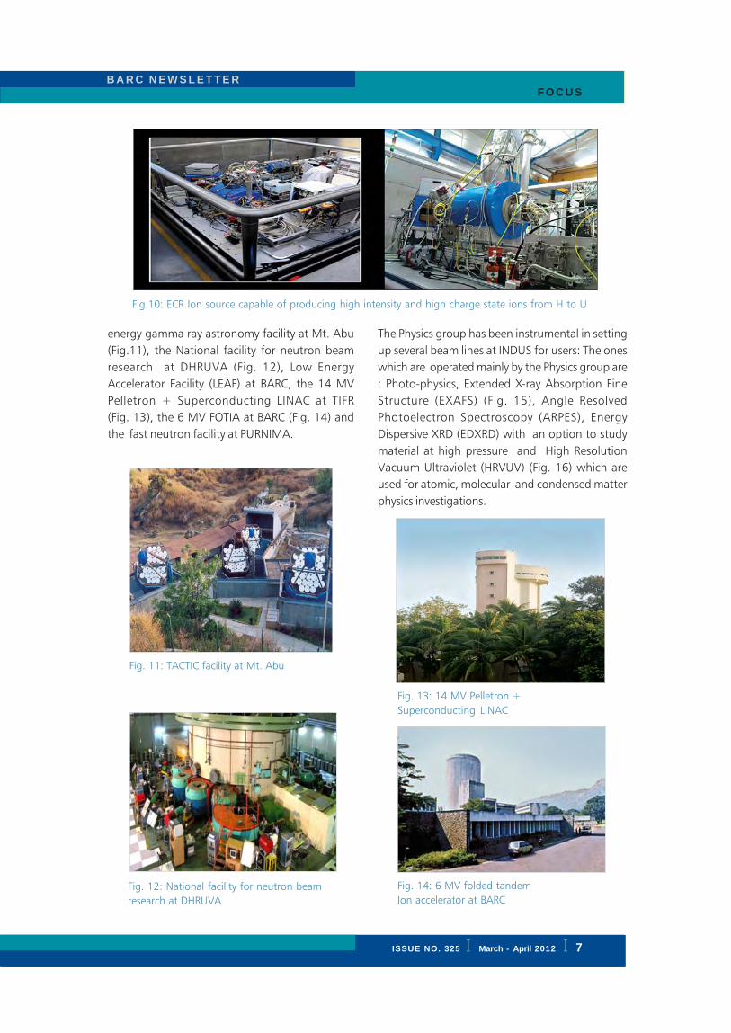
demonstrated (Fig. 10).
Generation of quality manpower, particularly in
accelerator physics and technology, is crucial for
the future programmes of BARC / DAE. This is
relevant in the context of DAE with an ambitious
plan to use accelerators not only for multidisciplinary
basic research but also for applications which will
include healthcare, nuclear energy and national
security.
The PG is responsible for development and
commissioning of several state- of- the- art beam
lines at INDUS Synchrotron at RRCAT. Currently work
is progressing well on the following beam lines –
Photoabsorption ( PASS), Infra Red FTS, SAXS,
Imaging, and protein crystallography. When
completed in the next one year, the user community
will be able to pursue R & D programmes exploiting
these beam lines.
O & M of facilities
The S&T personnel of the Physics Group operate
and maintain a number of national facilities.
Amongst them, mention may be made of the
TACTIC high
moderator) to carry out neutron multiplication and
transport studies. The coupled operation of the
accelerator and the sub-critical core is a forerunner
to the ultimate ADS, a long term programme of
the DAE (Fig. 8). Another flagship programme in
which the PG is taking a lead role is the design and
development of the LEHIPA (Low Energy High
Intensity Proton Accelerator) which can serve as an
injector of the high energy, high intensity accelerator
(1 GeV, mAs) to be built as part of the Indian ADS
programme. The LEHIPA consists of an ECR source,
RFQ and DTL modules , high voltage power supplies,
high power RF systems, precision temperature
controlled LCW supply system and is designed to
accelerate the protons upto 20 MeV with mAs
intensity (Fig. 9). It is a challenging assignment and
the project is planned for installation and
ISSUE NO. 324 I JAN. - FEB. 2012 I
B A R C N E W S L E T T E R BRIEF COMMUNICATION
B A R C N E W S L E T T E R F O C U S
ISSUE NO. 325 I March - April 2012 I 7
energy gamma ray astronomy facility at Mt. Abu
(Fig.11), the National facility for neutron beam
research at DHRUVA (Fig. 12), Low Energy
Accelerator Facility (LEAF) at BARC, the 14 MV
Pelletron + Superconducting LINAC at TIFR
(Fig. 13), the 6 MV FOTIA at BARC (Fig. 14) and
the fast neutron facility at PURNIMA.
The Physics group has been instrumental in setting
up several beam lines at INDUS for users: The ones
which are operated mainly by the Physics group are
: Photo-physics, Extended X-ray Absorption Fine
Structure (EXAFS) (Fig. 15), Angle Resolved
Photoelectron Spectroscopy (ARPES), Energy
Dispersive XRD (EDXRD) with an option to study
material at high pressure and High Resolution
Vacuum Ultraviolet (HRVUV) (Fig. 16) which are
used for atomic, molecular and condensed matter
physics investigations.
Fig.10: ECR Ion source capable of producing high intensity and high charge state ions from H to U
Fig. 11: TACTIC facility at Mt. Abu
Fig. 12: National facility for neutron beam
research at DHRUVA
Fig. 13: 14 MV Pelletron +
Superconducting LINAC
Fig. 14: 6 MV folded tandem
Ion accelerator at BARC

I ISSUE NO. 324 I JAN. - FEB. 2012
B A R C N E W S L E T T E RBRIEF COMMUNICATION
B A R C N E W S L E T T E RF O C U S
8 I ISSUE NO. 325 I March - April 2012
spectrometers –TIMS (Fig. 17), PGMS, ICPMS
(Fig. 18), QMS and D/H ratio mass spectrometer-
have been designed and indigenously developed
to meet the growing needs of the department of
DAE in general and RMP, AMD and HWB in
particular. Over the years nearly, 25 mass
spectrometers have been supplied to DAE users.
Powerful spectroscopic techniques (including PIXE,
XRF) have been employed to characterize a large
number of samples from different labs in DAE. Trace
analysis of nuclear and detector grade material is
being routinely carried out for various users. The
Atomic Emission Spectroscopy, ICP-based technique
and the Echelle Spectrometry are employed for
this progamme.
Fig. 17: TIMS for AMD
Fig. 18: Multicollector ICP – MS for RMP
Fig. 15: EXAFS beam line
Fig. 16: HRVUV beam line
All these facilities are catering to a large body of
users from the DAE and the universities.
Services
As part of the indigenous development of single
crystals which are technologically important and of
great relevance to DAE programmes, the Physics
Group has a sustained programme of growing single
crystals of different types. These include the laser
(PbMoO4, NaBi(WO
4)2, Nd:YAG, Pb
5Ge
3O
11 and
Li2B4O
7) and the detector (CsI(Tl) and LiF) materials.
Silicon surface barrier semiconductor detectors of
varying thicknesses (10 to 300 microns) and areas
(50 to 250 mm sq) have been fabricated and
supplied to the users. PG has a specialization in
developing BF3 and He3 filled neutron proportional
counters for many years and these have been
employed successfully in our programme and also
supplied to other users. The precision mass

ISSUE NO. 324 I JAN. - FEB. 2012 I
B A R C N E W S L E T T E R BRIEF COMMUNICATION
B A R C N E W S L E T T E R F O C U S
ISSUE NO. 325 I March - April 2012 I 9
The PG is playing a leading role in the newly created
Nuclear Data Physics Centre of India (NDPCI), which
coordinates the nuclear data activities of the country
and also interfaces with international agencies like
the IAEA.
Summary
To sum up, the Physics Group has been making
sustained and significant contributions to the R &
D programmes of DAE in general and BARC in
particular. The PG continues to hold a leading
position in the country, in the pursuit of basic
research addressed to frontiers in physics. In addition
the PG also has the mandate to run severed national
facilities catering to a large user community. One
may consider the present article as just an overview
of some of the important programmes of the Physics
Group. It is only a representative account and is in
no way exhaustive. Needless to say that much of
the success achieved by the PG in the various R & D
programmes would not have been possible without
the active involvement and constant cooperation of
colleagues from other Divisions / Groups of BARC but
also other units of the DAE.
Acknowledgement
It is a pleasure to thank my colleagues
Dr. S. L. Chaplot, Dr. A. Chatterjee, Dr. S. K. Gupta,
Dr. B. N. Jagatap, Shri. R. Koul, Shri. P. K. Nema,
Dr. N.K.Sahoo, Dr. S.M.Sharma, Dr. P. Singh and
Dr. A. Sinha for their inputs and discussions. I am
grateful to Dr. T. Mukherjee, Dr. K. Bhanumurthy
and Dr. A. K. Tyagi for the kind invitation to write this
article and useful suggestions.
Forthcoming Symposium
DAE – BRNS
Interdisciplinary Symposium
on Materials Chemistry
The 4 th DAE – BRNS Interdisciplinary
Symposium on Materials Chemistry will be held
at BARC, Mumbai, from Dec 11-15, 2012. It is
being organized by the Society for Materials
Chemistry & Chemistry Division, BARC. The
scientific programme of the Symposium will
cover the following topics: Nuclear materials,
High purity materials, Nanomaterials and
clusters, Carbon based materials, Surface
chemistry and thin films, Materials for energy
conversion, Magnetic materials and electro-
ceramics, Catalysis, Soft condensed matter,
Biomaterials and polymers.
Important Dates
Last date for submission : Aug. 31, 2012
of abstract
Acceptance notification : Sept. 28, 2012
Payment of registration fee : Oct. 31, 2012
For further details please visit the symposium
website: www.barc.gov.in/ismc-2012 or
contact:
Dr. D. Das
Convener, ISMC-2012
Chemistry Division, BARC,
Mumbai-400 085, India
Telephone: +91-22-25595102
Fax: +91-22-25505151
Email : [email protected]
Dr. A. K. Tyagi
Secretary, ISMC-2012
Chemistry Division, BARC,
Mumbai-400 085, India
Telephone: +91-22-2559 5330
Fax: +91-22-25505151
Email : [email protected]

I ISSUE NO. 324 I JAN. - FEB. 2012
B A R C N E W S L E T T E RBRIEF COMMUNICATION
B A R C N E W S L E T T E RREASEARCH ARTICLE
10 I ISSUE NO. 325 I March - April 2012
Photocatalytic Hydrogen Generation from Water
using Solar Radiation
R. Sasikala and S. R. BharadwajChemistry Division
Abstract
Solar photocatalytic water splitting is considered as a potential method for hydrogen production as both solar
energy and water are renewable. The major task is the design of suitable photocatalysts, which can work
efficiently under solar radiation, especially under visible light. The performance of the visible light active
photocatalysts synthesized till date is far from satisfactory for any practical applications, which necessitates a lot
more research and attention in this field. In the light of our recent findings, this article addresses the different
problems associated with the development and efficient utilization of solar energy for the photocatalytic water
splitting reaction.
1. Introduction
Hydrogen is considered as the energy carrier of
the future as no green house gas like CO2 is
emitted when hydrogen is burnt and it can be
generated from source like water. Attention was
focused on photocatalytic generation of hydrogen
from water after the discovery of Fujishima and
Honda [1], who demonstrated that overall water
splitting can be achieved using a
photoelectrochemical cell made of a single-
crystalline TiO2 (rutile) anode and a Pt cathode
under ultraviolet (UV) irradiation and operated with
an external bias. Over the past few decades, lot
of efforts have been made to produce hydrogen
from water photocatalytically and a number of
photocatalyts have been designed for this purpose.
Though TiO2 is an efficient, stable and cheap
photocatalyst for hydrogen generation from water,
its activity is limited to UV radiation, which is only
3-5% of solar radiation. Cadmium sulphide is
another widely studied visible light active
photocatalyst (bandgap 2.4 eV). However, the
disadvantage of using CdS is that it undergoes
photocorrosion in the absence of suitable sacrificial
reagents. Current research efforts are directed
towards the synthesis of visible light active and
stable semiconductor photocatalysts. As solar
radiation contains ~40% visible light and 3-5%
uv-radiation, different modifications and band
engineering of the UV-active photocatalyst are
done, to make it visible light active.
The target is to develop a photocatalyst having a
band gap (BG) of ~2eV for overall water splitting
and a solar energy conversion efficiency of 10%
(solar energy conversion efficiency is the ratio of
the chemical potential energy stored in the form
of hydrogen molecules to the incident radiation
of energy). A technical estimation has shown that
a one-third energy need in 2050 can be satisfied
with 10000 “solar plants” of dimension 5x5km
per plant with a solar energy conversion of 10%
[2]. The total area needed for this is 250000 km2,
which corresponds to ~1% of the earth’s desert
land. These plants will generate 570 tons of
hydrogen gas per day using an integrated solar
energy of AM1.5G (Air Mass 1.5 global spectrum,
it is the solar spectrum corresponding to 1.5 air
mass and to a solar zenith angle of 48.2o)
irradiation for a day. Hence, the primary focus has
to be on the development of suitable
photocatalysts for overall water splitting under solar
irradiation with the required solar energy
conversion efficiency.

ISSUE NO. 324 I JAN. - FEB. 2012 I
B A R C N E W S L E T T E R BRIEF COMMUNICATION
B A R C N E W S L E T T E R RESEARCH ARTICLE
ISSUE NO. 325 I March - April 2012 I 11
2. Photocatalytic water splitting by
semiconductors
When a semiconductor is exposed to a radiation
having energy equal to or greater than the bandgap
energy, an electron is excited from the valence
band (VB) to the conduction band (CB) leaving a
hole in the VB. The electron in the CB initiates the
reduction of H+ to hydrogen and the hole oxidises
water to generate oxygen. For these reactions to
take place, the VB potential must be more positive
than the oxidation potential of water
(1.23 V w. r. t. normal hydrogen electrode (NHE))
and CB potential must be more negative than the
reduction potential of water (0.0 V w. r. t. NHE).
A schematic illustration of the band structure of
TiO2 semiconductor and band potential
requirements for overall water splitting reaction are
shown in Fig. 1.
semiconductor. The higher the crystallinity, the
better is the probability that the charge carriers can
reach the surface without getting trapped by the
defects. If the particle size is small, the charge
carriers have to travel only a short distance to reach
the surface, which can enhance their life time. The
last step is the surface reaction of electron
combining with H+ to form hydrogen and hole
reacting with water to form oxygen. A number of
active sites on the surface will enhance these
reactions and hence higher surface area of the
catalyst is advantageous for this process.
Fig. 1: Schematic presentation of the band structure
of TiO2 semiconductor
There are three important steps associated with
the photocatalytic water splitting reaction as
illustrated in Fig. 2. The first step is the excitation
of the semiconductor. For the semiconductors to
be visible light active, the BG has to be less than
3 eV. The next step is the migration of the charge
carriers to the surface. This step is influenced by
the crystallinity and particle size of the
Fig. 2: Schematic presentation of the different steps
involved in a photocatalytic process
Incorporation of noble metals like Pt, Pd, and Rh
as co-catalysts on the surface of semiconductor
photocatalyst improves the photocatalytic activity
for hydrogen generation. The enhanced activity is
due to the interfacial transfer of electrons from
the photocatalyst to the metal when irradiated.
This process enhances the electron-hole separation
and minimizes the charge recombination. Besides
using co-catalysts, sacrificial reagents like
methanol, ethanol, etc. are used in photocatalytic
hydrogen production reaction to suppress the
electron-hole recombination.
3. Photocatalytic water splitting: current
scenario
A number of oxide photocatalysts have been
synthesized and tested for the photcatalytic water

I ISSUE NO. 324 I JAN. - FEB. 2012
B A R C N E W S L E T T E RBRIEF COMMUNICATION
B A R C N E W S L E T T E RREASEARCH ARTICLE
12 I ISSUE NO. 325 I March - April 2012
splitting reaction. The oxide catalysts suitable for
water splitting reaction are generally classified into
two groups. Among these, one group belongs to
cations with d0 (Ti4+, Zr4+, Nb5+, Ta5+ and W6+)
and other to d10 ( Ga3+, In3+, Sn4+, Ge4+, Sb5+)
electronic configurations. An apparent quantum
efficiency (product molecules formed per incident
photon (polychromatic)) of 64% has been obtained
for Pt/TiO2 photocatalyst when irradiated with UV
radiation of wavelength <300nm and in the
presence of ethanol as sacrificial reagent. A few
other oxides which exhibit photocatalytic activity
for water splitting reaction under UV radiation are
La doped NaTaO3, Sr
2M
2O
7 (M=Nb, Ta) etc.
Among these, NiO/NaTaO3:La photocatalyst shows
the highest activity with an apparent quantum yield
of 56% at 270 nm [3]. Among the visible light
active catalyst, the highest apparent quantum yield
of 5.9% (420-440nm) was reported for
(Ga0.88
Zn0.12
)(N0.88
O0.12
) catalyst with Rh2-y
CryO
3 as
co-catalyst from water + H2SO
4 at pH = 4.5 [4].
Among non-oxide photocatalysts, CdS is a highly
active visible light photocatalyst in the presence
of Na2S and Na
2SO
3 as sacrificial reagents. When
Pt and PdS are used as co-catalysts along with
CdS, an apparent quantum yield of 93% was
obtained at 420 nm in presence of Na2S and Na
2SO
3
as sacrificial reagents. The disadvantage of CdS
based photocatalyst is their instability in the
absence of suitable sacrificial reagent leading to
their photocorrosion.
4. Strategies employed for improving the
photocatalytic activity of semiconductor
photocatalyst
(i) Changing chemical composition
Doping with a suitable cation or/and anion can
alter the bandgap rendering it visible light active.
Though the cation doping can decrease the
bandgap, it forms discrete levels within the
bandgap forming trap levels. These defect/trap
levels can act as recombination centres for the
photogenerated electrons and holes leading to
decreased photocatalytic activity. Cationic dopant
like indium can contribute additional levels to the
conduction band of the semiconductor, which
decreases its bandgap. As the additional levels mix
with the CB, they do not act as electron traps
enhancing the photocatalytic activity. Doping of
oxide semiconductors with anionic dopants like N
or S leads to the mixing of the N 2p or S 3p
orbitals with the O 2p orbitals and a new VB is
created (Fig. 3). This process decreases the BG
without affecting the CB level. As a result, band
edge potentials are suitable for overall water
splitting.
Fig. 3: Schematic presentation of the modification of
the CB and VB of TiO2 due to In and N co-doping
(ii) Altering Physical properties
Improving physical properties like surface area and
crystallinity can enhance the photocatalytic activity.
Nanometer sized photocatlysts can be prepared
by solvothermal / hydrothermal synthesis, polyol-
mediated route, sol-gel synthesis, gel combustion
route etc. Calcination of these nanoparticles around
4000C gives nanocrystalline semiconductors having
a reasonably high surface area.
(iii) Minimizing the recombination of charge
carriers
Use of coupled semiconductors or co-catalysts can
enhance the activity of the photocatalyst. A
composite of two semiconductors in which the
CB potential of one is lower than that of the other
can enhance the photocatalytic activity as the
photogenerated electron can migrate to the CB of
the semiconductor, whose CB potential is lower.

ISSUE NO. 324 I JAN. - FEB. 2012 I
B A R C N E W S L E T T E R BRIEF COMMUNICATION
B A R C N E W S L E T T E R RESEARCH ARTICLE
ISSUE NO. 325 I March - April 2012 I 13
This process increases the life time of the charge
carriers. Noble metal co-catalysts also increase the
life time of the photogenerated electrons as stated
earlier (section 3). Noble metals can act as a sink
for the electrons, which enhances the liberation
of H+ as hydrogen gas from the noble metal sites.
5. TiO2 and CdS based Photocatalyst systems
Photocatalytic systems based on TiO2 and CdS have
been studied in our laboratory. Some interesting
results obtained from these studies are as follows.
(a) TiO2 dispersed on different supports
Titania was dispersed on different supports like
ZrO2, Al
2O
3, NaY zeolite and CeO
2 to study the
role of different supports on the photocatalytic
activity [5]. As these different oxides exhibit surface
acidity, it was of interest to investigate the role of
surface acidic sites on the photocatalytic activity
of TiO2. The surface acidity of these supports, as
measured by the pyridine adsorption method,
decreases in the order zeolite>ZrO2>Al
2O
3>CeO
2.
TEM images indicated that TiO2 was in a highly
dispersed state on ZrO2 support when compared
to other samples (Fig. 4). TiO2-ZrO
2 showed the
highest activity among these samples (Fig. 5,
Table 1). The enhanced activity of TiO2 dispersed
on ZrO2 is attributed to the enhanced optical
absorption due to the decreased band gap (~3.0
eV) and increased life time of the
photogenerated charge carriers assisted by the
surface acidic sites. Present study showed a
new result that a highly dispersed phase of
TiO2 on a support having higher surface acidity
exhibits enhanced photocatalytic activity. This
strategy may be useful for the design of new
catalysts yielding high photocatalytic activity.
(b) Indium doped CdS dispersed on ZrO2
Photocatalytic activity of In doped (2% by
atomic weight) CdS dispersed on ZrO2
(CdInS-Zr) was investigated, was compared
the activity with that of undoped CdS and
unsupported CdS [6]. The photocatalytic
activity of CdS improved when it was
dispersed on ZrO2 and it was further
enhanced when CdS was doped with indium
(Fig. 6). Hydrogen generation rate and the
apparent quantum efficiency are given in
Fig. 4: TEM image of TiO2 dispersed on
different support oxides
Fig. 5: Photocatalytic activity of TiO2 dispersed on
different supports. reaction conditions are given in
Table 1

I ISSUE NO. 324 I JAN. - FEB. 2012
B A R C N E W S L E T T E RBRIEF COMMUNICATION
B A R C N E W S L E T T E RREASEARCH ARTICLE
14 I ISSUE NO. 325 I March - April 2012
Table 1. The apparent quantum efficiency as a
function of wavelength for Pd-CdInS-Zr was
studied, using Xenon arc lamp as light source. It
is seen that an apparent quantum efficiency of
31% is obtained at λ > 420 nm. This system was
found to be stable throughout the experiment
(96 h) in the presence of Na2S and Na
2SO
3 as
sacrificial reagents. The enhanced photocatalytic
activity of this composite sample is attributed to
a synergistic combination of factors like enhanced
life time of the photogenerated charge carriers,
increased optical absorption compared to CdS-ZrO2
and improved surface area. It is proposed that the
increased life time of the charge carriers in the
supported system is due to the transfer of the
photogenerated electrons from the CB of CdS to
the surface states of ZrO2 (Fig. 7), which is
substantiated by the increased fluorescence life time
of the photogenerated charge carriers for the
supported CdS.
The photocatalytic activity of different systems
studied in our laboratory, the experimental
conditions employed and the apparent quantum
efficiencies obtained are summarized in Table 1.
6. Future scope
In order to meet the target of 10% solar energy
conversion efficiency, considerable amount of
research effort is required in the design of catalysts
which can work efficiently under solar radiation.
Careful choice of materials is required so that its
band gap is around 2eV and at the same time it
satisfies the band potential requirements. Sulphides
meet the BG requirement, but they are not stable
Fig. 6: Photocatalytic activity of different CdS samples
dispersed on different supports. Reaction conditions
are given in Table 1
Fig. 7: (left panel) Schematic illustration of the photogenerated electron transfer process from CdS to the
surface states of the ZrO2 support. (Right panel) Schematic energy level diagram of electron transfer process
from CdS to the surface states of ZrO2

ISSUE NO. 324 I JAN. - FEB. 2012 I
B A R C N E W S L E T T E R BRIEF COMMUNICATION
B A R C N E W S L E T T E R RESEARCH ARTICLE
ISSUE NO. 325 I March - April 2012 I 15
in the absence of sacrificial reagents. Some
oxynitrides and nitrides like TaON, Ta3N
5 are reported
to have BG of 2.4 and 2.0 eV respectively, but
the quantum efficiency is far from satisfactory.
Rh:Cr2O
3/Ga
1-xZn
xN
1-xO
x is found to be active for
overall water splitting, but the quantum yield is
low. Though most of the oxides are stable catalysts,
the VB and CB energy requirements for O2 and H
2
evolution, make it inefficient for visible light
photocatalytic reaction. Hence, it is important to
develop a library of photocatalysts to clarify
different factors influencing their photocatalytic
properties. For example, there is no clear
understanding of the role of different structures
and shapes of the photocatalysts on the
photocatalytic activity. Several detailed studies are
required to understand these factors, which will
be helpful for the design of new highly active
photocatalysts for water splitting.
Acknowledgements
Authors gratefully acknowledge the constant
encouragement of Dr. D. Das, Head, Chemistry
Division during the course of this work.
References
1. A. Fujishima, K. Honda, Nature 238 (1972)
37-37.
2. K. Maeda, K. Domen, J. Phys. Chem. Lett. 1
(2010) 2655-2661
3. H. Kato, K. Asakura, A. Kudo, J. Am. Chem.
Soc. 125 (2003) 3082-3089.
4. K. Maeda, T. Takata, M. Hara, N. Saito, Y.
Inoue, H. Kobayashi, K. Domen, J. Catal., 254
(2008) 198-204.
5. R. Sasikala, A.R. Shirole, V. Sudarsan, V.S.
Kamble, C. Sudakar, R. Naik, R. Rao,
S.R. Bharadwaj, Appl. Catal. A: General 390
(2010) 245-252.
6. R. Sasikala, A. R. Shirole, V. Sudarsan, K. G.
Girija, R. Rao, C. Sudakar, S. R. Bharadwaj
J. Mater. Chem., 21 (2011) 16566 – 16573
Table 1: Summary of the photocatalytic activity results obtained in our laboratory using sun light type radiation
(*Spectrum of the lamp consisted of fluorescent emission predominantly in the visible region along with a UV
contribution of ~3%)
No Systems studied Experimental H2
AQEconditions generation Light source:
rate *fluorescent(L/h/m2/g) lamp (%)
1 TiO2 doped with Sn &Eu: Pd 200mg catalyst, 0.35 1.7
co-catalyst 25ml water, 5 mlCH
3OH
2 Ti3+ doped TiO2 synthesized 50mg catalyst, 0.60 2.1
by solvothermal method:Pd 25ml water, 5 mlco-catalyst CH
3OH
3 TiO2- (2%)SnO
2 composite; 50mg catalyst , 0.31 1.2
Pd Co-catalyst 25ml water, 5 mlCH
3OH
4 In & N co-doped TiO2: Pd 50mg catalyst , 0.28 1.1
co-catalyst 25ml water, 5 mlCH
3OH
5 30%TiO2-
dispersed on ZrO2: 50mg catalyst , 1.1 3.3
Pd co-catalyst 25ml water, 5 mlCH
3OH
6 In(2%) doped CdS 30(%) dispersed 50mg catalyst, 2.8 4.0on ZrO
2: Pd co-catalyst 12.5ml Na
2S +
12.5ml Na2SO
3
I ISSUE NO. 324 I JAN. - FEB. 2012
B A R C N E W S L E T T E RBRIEF COMMUNICATION
B A R C N E W S L E T T E RREASEARCH ARTICLE
16 I ISSUE NO. 325 I March - April 2012
Development of Carbon / Carbon Composites for
Nuclear Reactor Applications
Ramani Venugopalan and D. Sathiyamoorthy
Powder Metallurgy Division
and
A. K. Tyagi
Chemistry Division
Abstract
Carbon and carbon fiber reinforced materials are promising materials for use in nuclear reactors, due to their
excellent thermal and mechanical properties. In the present studies, experiments were carried out to prepare
carbon-carbon(C/C) composites using non-graphitizing precursors such as polyacrylonitrile (PAN) fiber and
phenolic resin matrix. A typical sample of C/C composite at 40 vol% of PAN fibre showed to be amorphous. These
fibers have been used to make a 2-D preform and phenol formaldehyde resin was impregnated, cured and
carbonized to form the matrix. Impregnation was carried out under different conditions, and its effect was
studied by XRD, Raman spectroscopy and XPS. The C/C composite samples have been irradiated by neutrons at
neutron flux of 1x10¹²n/cm2/s with varying fluences at 40°C. The stored energy is very less about 23.4 J/g and
43.3 J/g as compared to irradiated graphite. The composites were coated with silicon carbide (SiC) for improved
oxidation resistance by chemical vapor deposition technique.
Introduction
Carbon based materials due to their wide range of
structures and several desirable neutronic properties
are used in nuclear reactors and in the recent past
there has been growing interest to develop speciality
carbon for high temperature nuclear and fusion
reactors. Graphite was used in the first nuclear
reactor CP-1, constructed in 1942 at Stagg Field
University of Chicago. Some of the emerging
applications include their use as critical parts in
advanced nuclear reactors. Efforts are underway to
develop carbon materials with high density as well
as amorphous isotropic carbon for use in thermal
reactors. An amorphous structure is preferred in
order to avoid accumulation of Wigner energy,
which is the stored energy in graphite lattice due to
dislocation of atoms induced by irradiation.
Carbon fiber reinforced carbon matrix composites
or the so called carbon/carbon (C/C) composites
are a generic class of synthetic materials consisting
of carbon fibers reinforced in a carbon matrix. They
possess densities ranging from 1600–2000 kg/m3,
much lower than those of metals and ceramics.
They can be classified according to the type of
reinforcement used and also depending on the type
of process used for their manufacturing. Some of
the most important and useful properties of C/C
composites [1] are its light weight, high strength at
high temperature (3000°C) in non-oxidizing
atmospheres, low coefficient of thermal expansion,
high thermal conductivity, high thermal shock
resistance and low recession in high pressure ablation
environments. The mechanical strength of C/C
composites increases with temperature, in contrast
to the strength of metal and ceramics. The main
application areas of these are in defence, space and
aircraft industries which include brake discs, rocket-
nozzles etc. They also possess numerous
applications in the field of general mechanical
engineering. Carbon/carbon composite materials
[2-5] as against conventional graphite materials are
now contemplated as promising materials for the

ISSUE NO. 324 I JAN. - FEB. 2012 I
B A R C N E W S L E T T E R BRIEF COMMUNICATION
B A R C N E W S L E T T E R RESEARCH ARTICLE
ISSUE NO. 325 I March - April 2012 I 17
fusion reactor, due their high thermal conductivity
and high thermal resistance. C/C components
materials may be the choice for the next generation
Tokomak fusion reactors such as International
Thermonuclear Experimental Reactor (ITER) which
must endure severe environment including high-
heat fluxes, high armor, surface temperature and
eddy-current induced stresses during plasma
disruption.
The main objective of the investigation was to
fabricate C/C composites by impregnation method
and to characterize the final microstructure. Thermo-
physical properties of the carbon composite like
density, co-efficient of thermal expansion have been
evaluated. In the present studies, C/C composites
were developed using non-graphitizing precursors
such as polyacrylonitrile (PAN) carbon fiber and
phenolic resin matrix. The desired non-graphitic
composite material, having stability under
irradiation, was obtained after a judicious control
on the processing parameters.
Experimental
A suitable preform is the first step for manufacturing
the C/C composites. The preform not only imparts
the rigidity to the composite, but also incorporates
the properties of fiber that eventually determine the
properties of the composites. The preforms were
made using PAN carbon fibers which were matted
and stacked to a 2-D preform using phenol
formaldehyde resin. Rectangular green preforms
were cut into 1´´x 1´´ x 0.4´´ size and carbonized
at a slow heating rate. The carbonized sample is
highly porous and has been densified by
impregnation (two cycles) with liquid phenol
formaldehyde resin, under pressures in steps of 30,
50 and 70 bar and time duration in steps of 10, 15,
20 and 25 hours. The impregnation unit is shown
in Fig. 1. The composite was densified by
impregnating the 2D preforms with liquid phenol
formaldehyde resin under high pressure and then
carbonizing them by slowly heating at 1000°C as
shown in Fig.2.
Characterization of the samples
The composites were thoroughly characterized by
X-ray Diffraction (XRD), X-ray tomography and
Raman Spectroscopy. Raman spectroscopy and
X-ray photoelectron spectroscopy (XPS) have been
used to estimate the ratio of sp2 to sp3 bonded
carbon atoms (i.e. sp2-C/sp3-C) in a few
representative composites impregnated at different
pressures and for different times. The C/C composite
samples have been irradiated with thermal neutrons
at APSARA Reactor. These irradiated samples were
characterized before and after irradiation for various
structural parameters like extent of local ordering
along c-axis, the average spacing of the d(002)
i.e.Fig.1: Indigenously fabricated Impregnator
un i t
Fig.2: Flow-sheet for the preparation of C/C
Composite

I ISSUE NO. 324 I JAN. - FEB. 2012
B A R C N E W S L E T T E RBRIEF COMMUNICATION
B A R C N E W S L E T T E RREASEARCH ARTICLE
18 I ISSUE NO. 325 I March - April 2012
the (002) crystallographic planes using X-
ray diffraction (XRD) technique. The
salient observations were further validated
using Raman spectroscopy. The fluences
used were 2.52 x 10¹⁶ n/cm2, 5.04 x 10¹⁶
n/cm2and 7.2 x 10¹⁶ n/cm2 at temperature
of 313 K during the irradiation. The stored
energy in the composites due to irradiation
was measured using DSC.
All the composites were found to be
amorphous in nature with no induced
graphitization in them. The interlayer
spacing (d002
) was calculated from
the (002) peak maximum (under
approximation of Gaussian line profile with
a linear background) using Bragg’s law
[6,7]. The d002
values decreased almost
linearly with pressure indicating an
increased ordering in the samples at higher
impregnation pressures. Local ordering in the
composites at higher impregnation pressure is
reflected in the concomitant grain growth along c-
axis. Grain size (Lc) along c-axis has been
approximately calculated from the (002) XRD peak
broadening using Scherrer equation.
The derived material contains the disordered carbon
phase which may contain both sp2 and sp3-bonded
carbon atoms. Raman spectroscopy and XPS have
been used to estimate [8] the ratio of sp2 to sp3
bonded carbon atoms (sp2-C/sp3-C) composites. The
D/G ratio has been used to estimate sp2-C/sp3-C in
the carbon composites from the Raman spectra of
the samples which were fitted with multi-Lorentzian
line-shape. In the XPS spectra, the peaks at 283.4
and 285eV are respectively attributed to sp2 and
sp3 bonded carbon atoms. Ratio of the peak areas
under the first two component curves provides a
direct estimate of sp2-C/sp3-C in the composites.
During the densification process there is increasing
Lc and sp2-C fraction.
Fig. 3(a-c) shows the scanning electron microscopy
(SEM) images of three representative samples
impregnated at 30, 50 and 70 bar respectively that
illustrates the formation of carbon composite at the
interface of PAN fibers. The micrographs also provide
information on the population and 2D distribution
of pores in the samples and hence on the effect of
impregnation pressure on the growth of secondary
carbon phase between two or more existing carbon
particles.
The neutron irradiated carbon composite samples
were characterized by XRD and Raman spectroscopy
before and after neutron irradiation. DSC studies
have also been carried out [9] to investigate the
stored energy release behavior due to irradiation.
From the XRD analysis of the irradiated and
unirradiated samples, it is found that the value of
d002
peak for the unirradiated samples is higher than
that of the irradiated samples indicating the
tendency to get ordered structure which was also
inferred from the Raman spectroscopy. The stored
energy release studies indicate, that simple defects
created due to low fluence of irradiation are annealed
by heating (accompanied by release of the stored
energy at lower temperature) and on the other hand
the complex defects which are formed require high
temperatures for annealing. The flux/fluence used
is lower than the actual scenario in the upcoming
Compact High Temperature Reactor; however the
present study could be an initial step in the direction
of investigation of damage caused by neutrons on
Fig. 3(a-c): SEM micrographs of three composites impregnated at
different pressures

ISSUE NO. 324 I JAN. - FEB. 2012 I
B A R C N E W S L E T T E R BRIEF COMMUNICATION
B A R C N E W S L E T T E R RESEARCH ARTICLE
ISSUE NO. 325 I March - April 2012 I 19
carbon/carbon composite materials for its use in
the upcoming reactor.
Although the C/C composites possess excellent
properties, they are prone to oxidation at high
temperatures when exposed to oxidizing
atmospheres. Therefore, these composites were
given protective coating [10-13]. SiC is a material
with high temperature oxidation resistance along
with good thermal shock properties and stability
against hot corrosion. Among the different
techniques to grow SiC on different substrates, the
Chemical Vapor Deposition (CVD) is the most
frequently used technique, as it can deposit materials
with near theoretical density and good adherence
to the substrate. SiC coating can be formed by using
various Si and C compounds. In the present work,
the coating was carried out with methyl
trichlorosilane (MTS) as the SiC precursor. Extensive
studies on coating with SiC by CVD technique using
a hot wall reactor with methyl trichlorosilane was
carried out at 1673 K. The effect of the operating
parameters such as MTS, hydrogen flow rate and
feed rate of MTS were studied.
The SiC coatings have been characterized using X-
ray Diffraction (XRD) and Raman spectroscopy for
phase identification. Scanning electron microscopy
(SEM) analysis with EDS was also carried out for
microstructure and elemental analysis. The
photograph of coated sample and the SEM image
of the SiC coating are shown in Figs. 4 & 5,
respectively.
Conclusion
C/C composites with density of 1470 kg/m3 were
developed with two cycles of impregnation and
carbonization. These composites are amorphous in
nature as revealed from the XRD even on heat
treatment at 18000C. The concerted study on the
effect of processing parameters on the porosity,
structure and properties of carbon-carbon
composites show that impregnation pressures,
especially high pressure, is more effective in
decreasing open porosity of the carbon/carbon
composites and hence in their densification than
impregnation time at relatively lower pressures. X-
ray tomography showed visible decrease in the
number of cracks and better matrix-resin bonding
at higher pressures. Structural ordering takes place
during the densification process as is evident from
decreasing d002
and increasing Lc and sp2-C fraction.
Formation of micro/nano-scopic graphitic domains
is believed to have been responsible for such short-
range ordering and it was found to be more at
higher impregnation pressures or when the samples
were subjected to high temperature treatment. From
the XRD analysis of the irradiated and unirradiated
samples, it is found that the value of d002
peak for
the unirradiated samples is higher than that of the
irradiated samples indicating the tendency to get
ordered structure. This is also inferred from theFig. 4: Dense SiC coated C/C sample
Fig. 5: SEM of SiC coated C/C sample

I ISSUE NO. 324 I JAN. - FEB. 2012
B A R C N E W S L E T T E RBRIEF COMMUNICATION
B A R C N E W S L E T T E RREASEARCH ARTICLE
20 I ISSUE NO. 325 I March - April 2012
Raman spectroscopy. The results of irradiation studies
indicate that simple defects created due to low
fluence of irradiation are annealed by heating
accompanied by release of the stored energy at
lower temperature. On the other hand the complex
defects require high temperatures for annealing
these defects. SiC coating on C/C composites was
achieved using CVD technique. The coating were
dense isotropic β-SiC phase. The major outcome of
the above investigations was establishing the fact
that the C/C composites are potential candidate
structural materials for low temperature reactor
applications.
Acknowledgement
Dr. Mainak Roy is thanked for useful discussion on
Raman data.
References
1. Schmidt DL, Davidson KE, Theibert LS, Unique
applications of carbon- carbon composite
materials. SAMPE J. 35(3) (1999): 27, 35(4)
(1999):51, 35 (5) (1999)47.
2. Graphite Moderator Lifecycle Behavior, IAEA –
Tecdoc. 32 (1998) 32.
3. B. T. Kelly and T. D Burchell, Carbon. 499
(1994) 32.
4. R. E. Nightingale, Nuclear Graphite (Academic
Press, New York, London) 1962.
5. T. D. Burchell, Carbon Materials for Energy
production and Storage, In Design and Control
of structure of Advanced Carbon materials for
Enhanced Performance. B. Rand et al, editor.
Kluwer Academic Publishers., 277-294, 2001
6. Marie J, Mering J. Chem. Phys. Carbon. 125
(1970) 6.
7. Warren BE. X-Ray Diffraction in Random Layer
Lattices. Phys. Rev. 59 (1941) 693.
8. Yu O, Daoyong L, Cao W, Shi S, Chen L. A
Temperature Window for the Synthesis of Single-
Walled Carbon Nanotubes by Catalytic Chemical
Vapor Deposition of CH4 over Mo2-Fe10/MgO
Catalyst. Nanoscale Research Letters. 4
(2009 )574
9. Venugopalan R, Sathiyamoorthy D, Acharya R,
Tyagi AK. Neutron irradiation studies on low
density pan fiber based carbon/carbon
composites. J. Nucl. Mater. 404 (2010) 19.
10. Fritze H, Jojie J, Witke T, Ruscher C, Weber S,
Scherrer S, etal., J. Eur. Ceram. Soc. 18-23
(1988) 51
11. F. Smeacetto and M. Ferraris, Carbon.40 (2002)
583.
12. K. L. Choy, Prog. Mater. Sci. 48 (2003) 57.
13. Y. J. Lee, D. J. Choi, S.S. Kim, H. L. Lee, H.D.
Kim, Surf. Coat. Technol. 177-178 (2004) 415.

ISSUE NO. 324 I JAN. - FEB. 2012 I
B A R C N E W S L E T T E R BRIEF COMMUNICATION
B A R C N E W S L E T T E RTECHNOLOGY DEVELOPMENT ARTICLE
ISSUE NO. 325 I March - April 2012 I 21
Uranium compound UAl4
UAl3
UAl2
UO2
U3Si
2U
3Si U
6Mn U
6Fe U
6Ni
Density (gm/cc) 6.1 6.8 8.1 10.96 12.2 15.3 17.2 17.4 17.6
Development and Fabrication of LEU Plate Fuel forModified Core of APSARA Reactor
1.0 Introduction
Till mid 70’s most of the research and test reactors
worldwide were using High Enriched Uranium
(HEU>85%U235) plate type dispersion fuel elements,
generally consisting of UAlx (mainly UAl
3) or U
3O
8
dispersed in aluminium matrix and with Al-alloy clad
[1]. In the late 70’s, the Reduced Enrichment for
Research and Test Reactor (RERTR) programme was
initiated, to address the proliferation concerns and
diversion issues. Since then it has become an
international norm for both designing fuels for new
reactors and for replacing the existing cores with
Low Enriched Uranium (LEU<20%U235) fuel.
The objective of using LEU as fuel is addressed by
increasing the fuel volume fraction in the meat and
by using higher density uranium compounds/alloys.
It is also important to note, that achieving highest
density in the fuel meat by using uranium as
dispersoid is not feasible due to the poor irradiation
and chemical stability of its lower temperature
orthorhombic α−phase. It is also well known, that
the cubic γ-phase of uranium has low swelling
characteristics but it is thermodynamically unstable
and cannot be retained at room temperature. The
solid solubility of uranium is very poor with many
elements of periodic table due to its 5f electron
behaviour, however it shows some alloying
characteristics with transition elements [2-4]. The
density of various uranium compounds is shown in
Table 1. The compounds of U6X (X: Mn, Fe, Ni)
and U3Si have higher density than U
3Si
2 but they
have not been favored for application as fuel because
of their higher swelling behaviour. Some of these
high density compounds are formed by peritectoid
reaction as compared with U3Si
2 which is a
congruent melting compound. The moderate
density and low swelling behaviour of U3Si
2
compound has attracted fuel designers for its
application as an alternate fuel in place of low
density UAl3 compound. However there is a
limitation on increasing the fuel volume in the matrix
beyond 55% [5-8]. Hence, in order to achieve the
G. J. Prasad, V. P. Sinha and P. V. Hegde
Metallic Fuels Division
Abstract
An indigenous Low Enriched Uranium (LEU: U235≅17wt%) based U3Si
2 dispersed in aluminium matrix plate fuel
has been developed, to replace the present imported High Enriched Uranium (HEU: U235≅93wt%) core of
APSARA reactor. New plate fuel development and fabrication laboratory has been setup at the Metallic Fuels
Division (MFD), BARC. The fabrication of LEU plate fuel for modified core of APSARA reactor has commenced in
this facility in January 2012. With modified core, the power of APSARA reactor will increase from 1 MW to 2 MW
and thermal neutron & fast neutron fluxes will be enhanced by almost 6.3 & 15 times respectively.
Table 1: Density of various uranium compounds

I ISSUE NO. 324 I JAN. - FEB. 2012
B A R C N E W S L E T T E RBRIEF COMMUNICATION
B A R C N E W S L E T T E R
22 I ISSUE NO. 325 I March - April 2012
TECHNOLOGY DEVELOPMENT ARTICLE
desired heavy metal density in the fuel meat to
compensate loss of enrichment, higher density
uranium compounds/alloys were developed.
At MFD, BARC, a new plate fuel development and
fabrication laboratory has been setup and a suitable
process flow sheet has been developed to fabricate
LEU based U3Si
2 dispersed plate fuel elements for
modified core of APSARA reactor. Two model fuel
assemblies with natural uranium and conforming
to specifications of modified APSARA core have
been fabricated using standardized process
parameters. The new facility has been inaugurated
by Director, BARC on January 16, 2012 (see Fig. 1)
and has started receiving LEU metal powder for
further processing.
2.0 Fabrication Work
2.1 Preparation of U3Si
2 compound
The starting material used for the synthesis of U3Si
2
compound is uranium metal powder and high purity
& low boron grade silicon powder. Silicon powder
was prepared by crushing silicon chunks in a jaw
crusher followed by sieving. Extreme care was taken
throughout the powder handling operation to avoid
any oxidation of powders for which the entire powder
handling operation was carried out inside a train of
glove boxes maintained under high purity argon
atmosphere. The process flow sheet for the
preparation of U3Si
2 granules was initially
standardized to one kilogram batch size which has
now been scaled up to a batch size of around
2.5 Kg (see Fig. 2).
To start with, uranium metal powder and silicon
powder were weighed in the required proportion
Fig. 1: Photograph of inauguration of plate fuel
fabrication facility by Dr. R. K. Sinha, Director, BARC
on January 16, 2012
Fig. 2: Flow-sheet for fabrication of U3Si
2 fuel granules by powder metallurgy route

ISSUE NO. 324 I JAN. - FEB. 2012 I
B A R C N E W S L E T T E R BRIEF COMMUNICATION
B A R C N E W S L E T T E RTECHNOLOGY DEVELOPMENT ARTICLE
ISSUE NO. 325 I March - April 2012 I 23
and were mixed in a cubical blender for 6 hours to
ensure good homogeneity between the constituents.
The mixture was then compacted in a hydraulic
press in the form of cylindrical pellets. During
compaction, no admixed binder/lubricant was
added to the mixture and only die-wall lubrication
was used. The pellets were compacted at 600 MPa
pressure in a 20 mm diameter pellet with L/D ratio
at around 0.5 to 0.75. The green pellets were then
loaded in molybdenum trays coated with plasma
sprayed yttria and were heated inside 10 kW
resistance heating furnace with graphite as heating
element. Synthesis was carried out under vacuum
of ~1.33 Pa at 1500±100C for 4 h. During the
heating cycle, intermittent soak was given at
11000C and 14000C for one hour each. The synthesis
temperature was kept well below the melting point
of U3Si
2 to avoid formation of any liquid phase and
hence to eliminate any impurity pickup.
After cooling the furnace to room temperature, the
synthesized U3Si
2 clinkers were taken out and
crushed to required size. Crushing was done in
glovebox maintained under argon atmosphere due
to the pyrophoric nature of the silicides, particularly
in powder form [9]. A photograph of fuel granule
production facility is shown in Fig. 3.
2.2 Fabrication of fuel plates
The fuel plates of U3Si
2 particles dispersed in
aluminium matrix and with Al-alloy clad were
fabricated by mixing U3Si
2 granules and aluminium
metal powder in the required proportion. This
mixture was then compacted in 800 ton single
action hydraulic press at 900 MPa to get fuel meat.
The press was enclosed inside glovebox for inert
argon gas cover. The fuel meat was then picture
framed (see Fig 4) followed by welding along edges
to prepare fuel sandwich. A gap of around 20mm
was kept open at one side during edge welding of
sandwich to allow gases to escape out during hot
rolling. The sandwich was then soaked inside a
resistance heated furnace at 4500C for 4 hours under
vacuum and then hot rolling was carried out in
multiple passes with intermittent soaking. Final plate
dimension was achieved by cold rolling operation.
Fuel plates passed through blister test were cleaned
chemically in a 2.5 N NaOH solution for 5 minutes
to remove any embedded contamination and the
stains. Then X-ray radiography was carried out to
locate fuel meat boundary and uranium distribution
Fig. 3: Photograph of U3Si
2 fuel granule production
facility
Fig. 4: Sketch of fuel-clad sandwich showing picture
frame, fuel meat and cover plates
in the meat at 32.0 KV and 96.0 KV respectively.
Based on the X-ray image, the outer boundary was
located and trimming was carried out to get required
dimension fuel plate.
2.3 Fabrication of fuel assembly
The finished fuel plates were then subjected to roll
swaging operation to fabricate square cross section
fuel boxes of Standard Fuel Assembly (SFA) and
Control Fuel Assembly (CFA). Once these fuel boxes
were prepared by swaging, the end fittings were
welded for fabrication of complete fuel assembly.

I ISSUE NO. 324 I JAN. - FEB. 2012
B A R C N E W S L E T T E RBRIEF COMMUNICATION
B A R C N E W S L E T T E R
24 I ISSUE NO. 325 I March - April 2012
TECHNOLOGY DEVELOPMENT ARTICLE
Process flow sheet developed for fabrication of
Al-alloy clad U3Si
2-Al plate fuel assembly is shown
in Fig. 5.
The photograph of plate fuel development and
fabrication laboratory with process equipment has
been shown in Fig. 6. The facility was inaugurated
by Director, BARC on January 16, 2012
(see Fig. 1).
3.0 Acceptance criteria
The uranium silicide compound (U3Si
2) prepared by
powder metallurgy route is characterized by
Fig. 5: Process flow sheet followed for fabrication of Al alloy clad U3Si
2-Al plate fuel assembly

ISSUE NO. 324 I JAN. - FEB. 2012 I
B A R C N E W S L E T T E R BRIEF COMMUNICATION
B A R C N E W S L E T T E RTECHNOLOGY DEVELOPMENT ARTICLE
ISSUE NO. 325 I March - April 2012 I 25
chemical analysis to determine uranium, silicon and
impurity contents. Typical chemical analysis of a
batch of U3Si
2 clinker is given in Table 2. Phase
analysis was also carried out by X-ray diffraction
technique (see Fig. 7). The XRD pattern (Fig. 7)
confirms the presence of U3Si
2 as major phase and
no other silicides are present in significant quantity.
Powder metallurgy route employed for synthesis of
U3Si
2 compound results in homogeneous product.
Metallography was carried out and microstructures
were developed using optical and electron
microscopy (Fig. 8). In addition, the microstructures
have revealed the presence of intragranular porosity
in the fuel compound. The results of X-ray
radiography (see Fig. 9) on fuel plates have shown
around 4.4 gm/cc of uranium loading in the fuel
meat. The plates were also examined
metallographically for the clad and fuel meat
thickness (see Fig. 10). A Standard Fuel Assembly
(SFA) photograph is shown in Fig. 11.All fuel plates
were blister tested at 5000C for 30 minutes under
Fig. 6: Photograph of (a) plate fuel development and fabrication laboratory,
(b) Real time X-ray radiography system
Fig. 7: X-ray diffraction pattern of U3Si
2 clinker
Element U Si C O N B
Concentration (wt%) 92.5±0.1 7.1±0.1 0.178 0.138 0.025 0.0001
Table 2: Chemical analysis of U3Si
2 compound
Fig. 8: Microstructure of U3Si
2 clinker
(a) Optical, (b) SEM
(a) (b)

I ISSUE NO. 324 I JAN. - FEB. 2012
B A R C N E W S L E T T E RBRIEF COMMUNICATION
B A R C N E W S L E T T E R
26 I ISSUE NO. 325 I March - April 2012
TECHNOLOGY DEVELOPMENT ARTICLE
vacuum and then each plate has been examined
visually for presence of any blister. Presence of any
blister will lead to rejection of fuel plate. Fuel plates
were also checked for presence of any loose and
fixed contamination. Metrology of hardware
components and final fuel assembly were also
carried out to qualify it as per the dimensional
specification of modified Apsara core.
4.0 Conclusion
Synthesis of U3Si
2 fuel granules by powder
metallurgy route was developed successfully. The
product (U3Si
2) prepared by powder metallurgy route
does not require any additional step for
homogenization unlike in melting casting route. A
process flow sheet was also developed and
established for the fabrication of fuel plates with
4.4 gm/cc of uranium loading in the fuel meat.
Fuel plates were fabricated with minimum dog bone
region which complies with the specifications.
Blister test was carried out to determine non bond
region in the fuel plate. The calibration of digital
radiography grey value with uranium density was
also established for online determination of uranium
density in the fuel plates.
This work marks an important development which
can be used for proposed research reactor and core
conversion of existing reactors in the near future.
Acknowledgement
The authors place their deep sense of indebtedness
and gratitude to Dr. R. K. Sinha, Director, BARC for
the approval of the project and also for his valuable
guidance. The authors are grateful to Dr. A. K. Suri,
Director, MG and Dr. (Mrs) S. B. Roy, Head, UED
for the supply of uranium metal powder. The authors
express their sincere thanks to Shri V. K. Raina,
Director, RG and Head, RRDPD for the useful
discussion and providing necessary inputs in carrying
Fig. 9: X-ray radiography of plate fuel at (a) 32.0 KV, (b) 96.0 KV
Fig. 10: Metallography examination of fuel plate in
longitudinal direction
Fig. 11: Photograph of components and standard fuel assembly of modified core of APSARA reactor (a) Fuel
box, (b) Toe section, (c) Handling pin, (d) SFA

ISSUE NO. 324 I JAN. - FEB. 2012 I
B A R C N E W S L E T T E R BRIEF COMMUNICATION
B A R C N E W S L E T T E RTECHNOLOGY DEVELOPMENT ARTICLE
ISSUE NO. 325 I March - April 2012 I 27
out this work. The authors deeply acknowledge the
support and help provided by Dr. K. L. Ramakumar,
Director, RC&IG and Head, RACD in carrying out
chemical characterization. The authors also
acknowledge the timely support given by Shri Manjit
Singh, Director, DM&AG and Head, CDM in the
fabrication and supply of various hardware
components required for the project. The authors
acknowledge the help and engineering support
provided by Shri K. N. Mahule, Head, ED&DD, S/
Shri R. S. Prasad and R. K. Mittal of ED&DD in the
course of commissioning of plate fuel laboratory.
The authors would take to place on record their
deep gratitude to S/Shri H. S. Kamath and R. P.
Singh, former Directors of NFG for providing useful
guidance and encouragement. The authors
gratefully acknowledge the team effort and hard
work by all the scientific and technical staff members
of MFD especially S/Shri S. K. Pal, G. P. Mishra and
R.M Malagi.
References
1. R.F. Domagla, T.C. Wiencek and H.R. Tresh,
Nucl. Tech. 62 (1983)353.
2. G.L. Copeland, Performance of Low
Enrichement U3Si
2-Aluminium dispersion fuel
elements in the Oak Ridge Research Reactors,
Argonne National Laboratory Report, ANL/
RERTR/TM-10 (1987).
3. V.P. Sinha, G.J. Prasad, P.V. Hegde, R. Keswani,
C.B. Basak, S.Pal, and G.P.Mishra,
Development, Preparation and Characterization
of uranium molybdenum alloys for dispersion
fuel application, J. Alloys and Comp.
473(2009)238.
4. Jeong-Soo Lee, Chang-Hee Lee, Ki Hwan Kim,
Vyacheslav Em, Neutron diffraction study of
U-5.4wt% Mo alloy, J. Nucl. Mater.
280(2000)116.
5. J.P. Durand and Y. Fanjas, LEU fuel development
at CERCA: status as of October 1993,
Proceedings of the 16th International Meeting
on Reduced Enrichment for Research and Test
Reactors, Japan Atomic Energy Research
Institute Report, Oarai, Japan, JAERI-M 94-02,
71-78.
6. J.P. Durand, P. Laudamy and K. Richter,
Preliminary developments on MTR plates with
uranium nitride, Proceedings International
Meeting on Reduced Enrichment for Research
and Test Reactors, 18-23 September, Argonne
National Laboratory Report, ANL/RERTR/TM-20,
Williamsburg.
7. V.P. Sinha, P.V. Hegde, G.J. Prasad and H.S.
Kamath, Development of high density uranium
molybdenum alloys by powder metallurgy route
for dispersion fuel application in research and
test reactors, 17th Plansee Seminar, Reutte,
Austria, Vol. 1, (2009), RM 78/1-16
8. G.I. Snelgrove, The use of U3Si
2 dispersed in
aluminium in Plate-type Fuel Elements for
Research and Test Reactors, Argonne National
Laboratory Report, ANL/RERTR/TM-11 (1987).
9. V.P. Sinha, G.P. Mishra, S. Pal, K.B. Khan, P.V.
Hegde and G.J. Prasad, Development of powder
metallurgy technique for synthesis of U3Si
2
dispersoid, J. Nucl. Mater. 383(2008)196.

I ISSUE NO. 324 I JAN. - FEB. 2012
B A R C N E W S L E T T E RBRIEF COMMUNICATION
B A R C N E W S L E T T E R
28 I ISSUE NO. 325 I March - April 2012
TECHNOLOGY DEVELOPMENT ARTICLE
Zinc Oxide Nanowires for Gas Sensing Application
1. Introduction
One dimensional nanostructures of metal oxides
namely nanowires (NWs) have emerged as a general
platform for ultra-sensitive direct electrical detection
of biological and chemical species1,2. NWs in
particular, offer various advantages that include high
surface area to volume ratio, Debye length (the
distance over which a local electric field affects the
distribution of free charge carriers) comparable to
the target molecule, low power consumption,
possibility of high integration densities and ease of
incorporation into microelectronic devices. Among
various semiconducting oxide materials, ZnO has
generated a great deal of interest due to its direct
wide band gap of 3.37 eV, large exciton binding
energy of 60 meV, and processing advantages for
its nanostructures3. There are two different
approaches to the production of 1D structures: top-
down and bottom up technologies. The first one is
based on standard micro fabrication methods with
deposition, etching and ion beam milling on planar
substrates in order to reduce the lateral dimensions
of the films to the nanometer size. Electron beam,
focused ion beam, X-ray lithography, nano-
imprinting and scanning probe microscopy
techniques can be used for the selective removal
processes. The advantages are the use of the well
developed technology of semiconductor industry
and the ability to work on planar surfaces, while
disadvantages are their extremely elevated costs and
preparation times. Furthermore the 1D
nanostructures produced with these techniques are
in general not single-crystalline. The second
approach, bottom-up, consists of the assembly of
molecular building blocks or chemical synthesis by
vapor phase transport, electrochemical deposition,
solution-based techniques or template growth. Its
advantages are the high purity of the nano-crystalline
materials produced, their small diameters, the low
cost of the experimental set ups. The main
disadvantage is their integration on planar substrates
for the exploitation of their useful properties, for
example transfer and making contacts can be
troublesome.
Providing electrical contacts to NWs is often
considered as a complex and tedious process. An
electrical contact to sensors based on single NWs is
often realized using a ‘pick and place’ approach. In
this, NWs are first drop-casted or spin-coated onto
the substrates containing predefined electrodes and
then aligned using dielectrophoresis technique. To
assure proper contact, additional electrode material
Niranjan Ramgir, Niyanta Datta, Manmeet Kaur, S. Kailasaganapathi,
A. K. Debnath, D. K. Aswal and S. K. Gupta
Technical Physics Division
Abstract
We present the growth of ZnO nanowires (NWs) using vapor phase and hydrothermal methods. In order toinvestigate the gas sensing characteristics, two types of sensors were prepared: (i) mat-type and (ii) as-grown random network of ZnO NWs. Mat–type sensors detected H
2S at room temperature with fast
response and recovery times of 250 and 700 s, respectively. On the other hand, as-grown random networkof ZnO NWs were less sensitive to H
2S. However, modification of random networks by CuO layer improved
the sensing properties, which is explained on the basis of the formation and destruction of p-n junctionamong p-type CuO and n-type ZnO.
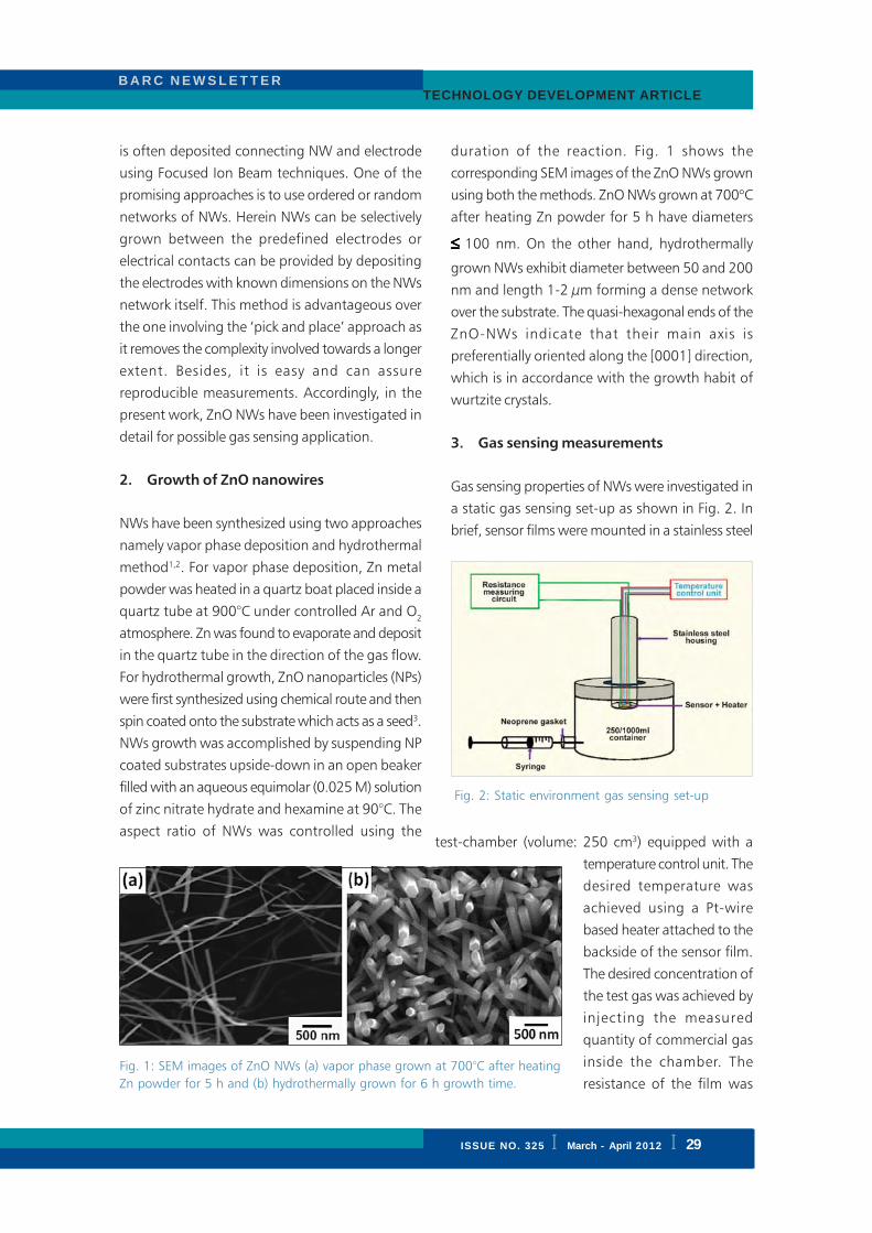
ISSUE NO. 324 I JAN. - FEB. 2012 I
B A R C N E W S L E T T E R BRIEF COMMUNICATION
B A R C N E W S L E T T E RTECHNOLOGY DEVELOPMENT ARTICLE
ISSUE NO. 325 I March - April 2012 I 29
is often deposited connecting NW and electrode
using Focused Ion Beam techniques. One of the
promising approaches is to use ordered or random
networks of NWs. Herein NWs can be selectively
grown between the predefined electrodes or
electrical contacts can be provided by depositing
the electrodes with known dimensions on the NWs
network itself. This method is advantageous over
the one involving the ‘pick and place’ approach as
it removes the complexity involved towards a longer
extent. Besides, it is easy and can assure
reproducible measurements. Accordingly, in the
present work, ZnO NWs have been investigated in
detail for possible gas sensing application.
2. Growth of ZnO nanowires
NWs have been synthesized using two approaches
namely vapor phase deposition and hydrothermal
method1,2. For vapor phase deposition, Zn metal
powder was heated in a quartz boat placed inside a
quartz tube at 900°C under controlled Ar and O2
atmosphere. Zn was found to evaporate and deposit
in the quartz tube in the direction of the gas flow.
For hydrothermal growth, ZnO nanoparticles (NPs)
were first synthesized using chemical route and then
spin coated onto the substrate which acts as a seed3.
NWs growth was accomplished by suspending NP
coated substrates upside-down in an open beaker
filled with an aqueous equimolar (0.025 M) solution
of zinc nitrate hydrate and hexamine at 90°C. The
aspect ratio of NWs was controlled using the
duration of the reaction. Fig. 1 shows the
corresponding SEM images of the ZnO NWs grown
using both the methods. ZnO NWs grown at 700°Cafter heating Zn powder for 5 h have diameters
≤≤≤≤≤ 100 nm. On the other hand, hydrothermally
grown NWs exhibit diameter between 50 and 200
nm and length 1-2 μm forming a dense network
over the substrate. The quasi-hexagonal ends of the
ZnO-NWs indicate that their main axis is
preferentially oriented along the [0001] direction,
which is in accordance with the growth habit of
wurtzite crystals.
3. Gas sensing measurements
Gas sensing properties of NWs were investigated in
a static gas sensing set-up as shown in Fig. 2. In
brief, sensor films were mounted in a stainless steel
Fig. 1: SEM images of ZnO NWs (a) vapor phase grown at 700°C after heating
Zn powder for 5 h and (b) hydrothermally grown for 6 h growth time.
test-chamber (volume: 250 cm3) equipped with a
temperature control unit. The
desired temperature was
achieved using a Pt-wire
based heater attached to the
backside of the sensor film.
The desired concentration of
the test gas was achieved by
injecting the measured
quantity of commercial gas
inside the chamber. The
resistance of the film was
Fig. 2: Static environment gas sensing set-up
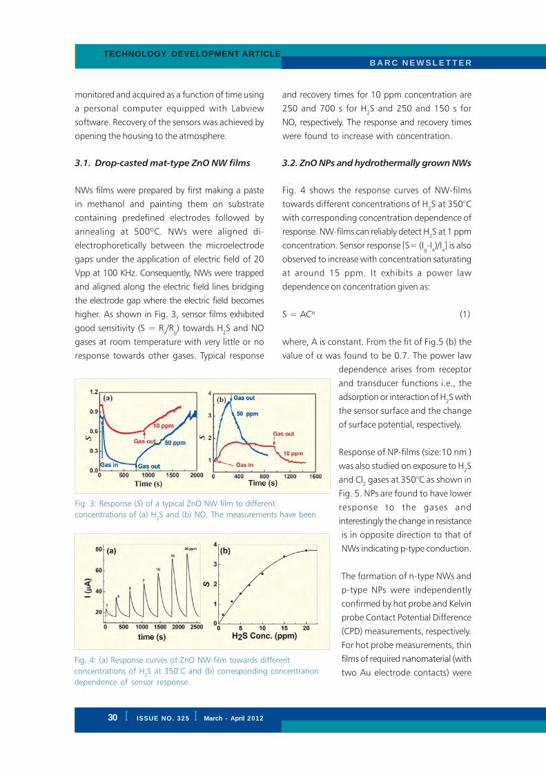
I ISSUE NO. 324 I JAN. - FEB. 2012
B A R C N E W S L E T T E RBRIEF COMMUNICATION
B A R C N E W S L E T T E R
30 I ISSUE NO. 325 I March - April 2012
TECHNOLOGY DEVELOPMENT ARTICLE
monitored and acquired as a function of time using
a personal computer equipped with Labview
software. Recovery of the sensors was achieved by
opening the housing to the atmosphere.
3.1. Drop-casted mat-type ZnO NW films
NWs films were prepared by first making a paste
in methanol and painting them on substrate
containing predefined electrodes followed by
annealing at 500ºC. NWs were aligned di-
electrophoretically between the microelectrode
gaps under the application of electric field of 20
Vpp at 100 KHz. Consequently, NWs were trapped
and aligned along the electric field lines bridging
the electrode gap where the electric field becomes
higher. As shown in Fig. 3, sensor films exhibited
good sensitivity (S = Ra/R
g) towards H
2S and NO
gases at room temperature with very little or no
response towards other gases. Typical response
and recovery times for 10 ppm concentration are
250 and 700 s for H2S and 250 and 150 s for
NO, respectively. The response and recovery times
were found to increase with concentration.
3.2. ZnO NPs and hydrothermally grown NWs
Fig. 4 shows the response curves of NW-films
towards different concentrations of H2S at 350°C
with corresponding concentration dependence of
response. NW-films can reliably detect H2S at 1 ppm
concentration. Sensor response [S= (Ig-Ia)/I
a] is also
observed to increase with concentration saturating
at around 15 ppm. It exhibits a power law
dependence on concentration given as:
S = ACα (1)
where, A is constant. From the fit of Fig.5 (b) the
value of α was found to be 0.7. The power law
dependence arises from receptor
and transducer functions i.e., the
adsorption or interaction of H2S with
the sensor surface and the change
of surface potential, respectively.
Response of NP-films (size:10 nm )
was also studied on exposure to H2S
and Cl2 gases at 350°C as shown in
Fig. 5. NPs are found to have lower
response to the gases and
interestingly the change in resistance
is in opposite direction to that of
NWs indicating p-type conduction.
The formation of n-type NWs and
p-type NPs were independently
confirmed by hot probe and Kelvin
probe Contact Potential Difference
(CPD) measurements, respectively.
For hot probe measurements, thin
films of required nanomaterial (with
two Au electrode contacts) were
Fig. 3: Response (S) of a typical ZnO NW film to different
concentrations of (a) H2S and (b) NO. The measurements have been
Fig. 4: (a) Response curves of ZnO NW-film towards different
concentrations of H2S at 350°C and (b) corresponding concentration
dependence of sensor response.

ISSUE NO. 324 I JAN. - FEB. 2012 I
B A R C N E W S L E T T E R BRIEF COMMUNICATION
B A R C N E W S L E T T E RTECHNOLOGY DEVELOPMENT ARTICLE
ISSUE NO. 325 I March - April 2012 I 31
heated from one end and the developed thermo-
e.m.f was measured. With the hot and cold probes
connected to positive and negative terminal of the
voltmeter respectively, a negative voltage for NP-
films and positive voltage for NW-films were
obtained, confirming the p-type and n-type nature
of NPs and NWs, respectively. Fermi level of a
semiconductor is close to conduction band for n-
type and to valence band for p-type materials.
Therefore, it is expected that the work function of a
material should increase when the nature of
conductivity changes from n to p-type. To confirm
difference in nature of conduction for NPs and NWs,
work function was scanned across the samples by
Kelvin probe. The average work functions of 4.8
and 5.3 eV for NW- and NP-films respectively is
obtained, which is in accordance with the change
in nature of conductivity from n to
p-type.
Cu is known to be an excellent promoter for H2S
causing an enhancement of both the sensitivity and
the selectivity of the sensor towards H2S.
Accordingly, we have investigated the effect of Cu
on H2S sensing properties of ZnO NWs7. The sensor
modified with 10 nm of Cu responded with
maximum sensitivity at an operating temperature
of 250°C. Fig. 6 shows the response curves recorded
towards increasing concentration of H2S. The sensor
exhibited a fast response and recovery times for
example, towards 5 ppm of H2S response and
recovery times were 62 and 150 s, respectively. This
fast response kinetics could be attributed to the
effective electron conduction pathway provided by
NWs.
In order to investigate the nature of interaction
between ZnO-NWs and CuO, we have carried out
photoluminescence (PL) studies (Fig. 7 (a)).
Both the ZnO-NW and CuO(10nm):ZnO-NW
random networks exhibit a peak at 384 nm
corresponding to a Near Band edge Emission (NBE).
ZnO-NWs network exhibited a broad band peak at
595 nm attributed to oxygen vacancies. For
CuO(10nm):ZnO-NWs network, this peak
broadens, intensifies and
shifts to higher wave
length (i.e. 627 nm). The
origin of such a peak
has been attributed to
the plasma resonances
of oxidized copper
aggregates. Interestingly
on CuO deposition NBE
peak quenches by ~42%.
This can be explained based
upon the formation of p-n
junction between p-type
Fig. 5. Response curves of ZnO NP-film towards 10
ppm of H2S and Cl
2 gases at 350°C
Fig. 6. (a) H2S response curves of CuO (10nm):ZnO-NWs measured at 200°C
(b) Variation of the sensitivity as a function of H2S concentration. Inset shows
enlarged view for CuO (100nm):ZnO-NWs sensor.

I ISSUE NO. 324 I JAN. - FEB. 2012
B A R C N E W S L E T T E RBRIEF COMMUNICATION
B A R C N E W S L E T T E R
32 I ISSUE NO. 325 I March - April 2012
TECHNOLOGY DEVELOPMENT ARTICLE
CuO and n-type ZnO, as schematically shown in
Fig. 7 (b). When a photon is incident on the sample,
electron gets excited into the conduction band
leading to the formation of an exciton. The p-n
junction enhances the dissociation of excitons as
ZnO transports electrons away and CuO transports
the holes. Dissociation of excitons greatly suppresses
the electron-hole recombination necessary for PL
emissions.
Fig. 7: (a) Room temperature PL spectra recorded for ZnO-NWs and CuO
(10nm):ZnO-NWs random networks. (b) Schematic representation of the
formation of p-n junction between CuO and ZnO and quenching of near-
band edge emission of ZnO due to dissociation of excitons.
In order to further investigate the
effect of p-n junction, we have
measured the room temperature
electrical resistance as a function
of CuO layer thickness. The
results unambiguously show that
the resistance increases sharply
upto a nominal thickness of 10
nm and then decreases
monotonically. The electrical
resistance (R1) of bare ZnO-NWs
network can be represented as the
series resistance of the ZnO-NWs
(RZnO
) and the junction resistance
formed between the NWs (RJN
)
(Fig. 8). The resistance (R2) of
ZnO-NWs network modified with a CuO layer upto
a nominal thickness of 10 nm can be represented
as a series equivalent to that of R1, p-n junction and
CuO aggregates. Due to the presence of p-n
junction, the value of R2 is expected to be very high.
However, at very high nominal thickness, CuO fully
covers the ZnO-NWs network. Thus a continuous
CuO layer acts as a parallel resistance, which reduces
the total resistance (R3) of the sample. Herein the
CuO layer contributes two resistances one
corresponding to CuO layer (RCuO
)
and the other corresponding to the
grain boundary (RGB
) resistance
between CuO grains. Thus
R1<R
2>R
3 is in accordance with
experimental results.
Modification of ZnO NWs network
with CuO (10 nm) results in the
formation of random n-p-n type
junctions. The potential barrier
formed at the ZnO/CuO/ZnO
heterojunction results in a very high
resistance of the film. Exposure to
H2S causes the potential barrier to
disappear. CuO reacts with H2S
forming CuS as per the following
reaction:
Fig. 8: Schematic representation of the equivalent electrical circuit of
different CuO:ZnO-NWs random networks

ISSUE NO. 324 I JAN. - FEB. 2012 I
B A R C N E W S L E T T E R BRIEF COMMUNICATION
B A R C N E W S L E T T E RTECHNOLOGY DEVELOPMENT ARTICLE
ISSUE NO. 325 I March - April 2012 I 33
CuO + H2S → CuS + H
2O (2)
CuS being metallic will destroy the n/p/n junction
as well as the potential barrier, and a new type of
n-ZnO/metallic-CuS/n-ZnO heterojunction will be
formed. The destruction of potential barrier results
in a sharp decrease in the electrical resistance.
During recovery, CuS reacts with oxygen forming
once again CuO. The potential barrier reappears due
to the formation of n-ZnO/p-CuO/n-ZnO
heterojunctions, and original high resistance is
regained.
4. Summary
ZnO NWs grown using both the physical as well as
the chemical methods have been investigated for
gas sensing applications. In particular, techniques
like vapor phase deposition and hydrothermal
growth were used effectively to realize these
nanostructures. Proper electrode contacts were
realized using dielectrophoresis technique and by
directly depositing the electrode over NW network
film. ZnO NPs exhibited a p-type response towards
gases while NW film detected H2S with faster
response and recovery time of 13 and 78 s,
respectively towards 20 ppm at 350°C. Cu
incorporation over NW surface has been
demonstrated to improve both the sensitivity and
the selectivity towards H2S. Our results clearly
illustrate that ZnO NWs are the potential candidates
for the realization of next generation of sensors.
Hopes are high that significant practical devices will
soon evolve from the integration of these structures
with conventional microelectronics.
Acknowledgements
This work is supported by “DAE-SRC Outstanding
Research Investigator Award” (2008/21/05-BRNS)
and “Prospective Research Funds” (2008/38/02-
BRNS) granted to D.K.A.
References
1. Aswal, D.K., Gupta, S.K. (eds), Science and
Technology of Chemiresistive Gas Sensors, Nova
Science Publisher, NY, USA, 2007. ISBN: 978-
160021-514-8.
2. Ramgir, N. S., Datta, N., Kaur, M., Debnath,
A. K., Aswal, D. K., Gupta, S. K.,
“Semiconductor nanowires and heterostructures
based gas sensors”, in Vincent Lefevre (Ed),
Nanowires: Properties, Synthesis and
Applications, Nova Science Publisher, NY 11788,
USA ISBN 978-1-61470-129-3 (2011) 1-46.
3. Ramgir, N. S., Rikka, V., Kaur, M., Kailasa
Ganapathi, S., Mishra, S. K., Datta, N., Aswal,
D. K., Gupta, S. K., Yakhmi, J. V., “ZnO
nanowires as H2S sensor”, CP1313 International
Conference on Progress in Emerging Functional
Materials, PEFM-2010,: 322-324.
4. Gupta, S. K., Ramgir, N. S., Kaur, M., Datta,
N., Saxena, V., Joshi, A., Singh, A., Aswal, D.
K., “Studies on polymer-ZnO nanowires
composites for gas sensing application”, World
Journal of Engineering, 7 (2010): 379-380.
5. Datta, N., Ramgir, N. S., M., Kailasa Ganapathi,
S., Debnath, A. K., Aswal, D. K., Gupta, S. K.,
“ZnO nanowires coated with CuO films as
highly sensitive H2S sensors”, TFST-2011, Indian
Vacuum Symposium on Thin Films: Science and
Technology, at BARC, Mumbai.
6. N. S. Ramgir, S. Kailasa Ganapathi, M. Kaur, N.
Datta, K. P. Muthe, D. K. Aswal, S. K. Gupta,
and J. V. Yakhmi, “Growth and gas sensing
characteristics of p and n-type
ZnONanostructures”, Sens. Actuators B 156
(2011): 875-880.
7. Datta, N., Ramgir, N. S., Kaur, M., Kailasa
Ganapathi, S., Aswal, D. K., Gupta, S. K.
“Selective H2S sensing characteristics of
hydrothermally grown ZnO-nanowires network
tailored by ultrathin CuO layers” Sens. Actuators
B 166-167(2012): 394-401.

I ISSUE NO. 324 I JAN. - FEB. 2012
B A R C N E W S L E T T E RBRIEF COMMUNICATION
B A R C N E W S L E T T E R
34 I ISSUE NO. 325 I March - April 2012
TECHNOLOGY DEVELOPMENT ARTICLE
Design and Application of a Formal Verification
Tool for VHDL Designs
1. Introduction
Computer-based Control and Instrumentation
(C&I) systems used in nuclear power plants are
mandated to undergo a rigorous verification
process commensurate with the safety class of
the system. The design of such systems involves
partitioning of the overall system functionality into
subparts, and implementing each subpart in
hardware and/or software as appropriate. Needless
to say the verification support for these systems
has to be tool-based, to make it rigorous,
repeatable and fast. We had identified various
areas in the system development life cycle where
such verification tools needed to be deployed.
Although commercial solutions are available in
some areas for verification of software and
hardware, scalability, technological obsolescence
and supply availability from foreign vendors always
remain in question. This is the main motivation
behind the ongoing programme at the Reactor
Control Division to develop indigenous tools for
software and hardware verification.
Many C&I systems are now increasingly using
FPGA devices, which allow configurability by the
hardware designer. The configurability is enabled
by the capability of “field programming” such
hardware devices using Hardware Description
Languages (HDL) like VHDL. Since the functional
bugs in such hardware subsystems used in C&I
of safety critical systems have disastrous
consequences, it is very much required that
verification techniques of equal rigour as the
software should also be applied to the design of
such hardware components. In fact, this is also
mandated by AERB safety guide D-25. This was
the motivation to develop a verification tool for
hardware designs which are synthesized and
configured into Field Programmable Gate Arrays
(FPGA). In this article, we discuss our efforts
towards the development of a verification tool
called VBMC for VHDL-based hardware design.
We also discuss few applications of this tool in
BARC. The tool has been developed in
collaboration with CFDVS, IIT Bombay, Mumbai.
Ajith K. John, A.K. Bhattacharjee, Mukesh Sharma, G. Ganesh,
S.D. Dhodapkar and B.B. Biswas
Reactor Control Division
Electronics and Instrumentation Group
Abstract
The design of Control and Instrumentation (C & I) systems used in safety critical applications such as nuclear
power plants involves partitioning of the overall system functionality into subparts and implementing each
subpart in hardware and/or software as appropriate. With increasing use of programmable devices like FPGA,
the hardware subsystems are often implemented in Hardware Description Languages (HDL) like VHDL. Since the
functional bugs in such hardware subsystems used in safety critical C&I systems have disastrous consequences,
it is important to use rigorous reasoning to verify the functionalities of the HDL models. We describe our work
on developing a software tool named VBMC (VHDL Bounded Model Checker) for mathematically proving
functional properties of hardware designs described in VHDL. It is based on the principle of bounded model
checking. Although the design of VBMC is still evolving, it is currently also being used for the functional
verification of FPGA based intelligent I/O (EHS) boards developed in Reactor Control Division, BARC.

ISSUE NO. 324 I JAN. - FEB. 2012 I
B A R C N E W S L E T T E R BRIEF COMMUNICATION
B A R C N E W S L E T T E RTECHNOLOGY DEVELOPMENT ARTICLE
ISSUE NO. 325 I March - April 2012 I 35
2. Background of Hardware Verification
Traditionally, the functional verification of HDL
designs has been done by simulation or testing.
However, exhaustive testing covering the entire
behaviour space of the design is impractical for
designs of even medium size and complexity. It
is now recognized that formal verification
provides a complementary approach to simulation
and testing by unravelling the corner cases of
the behaviour space quickly.
Hardware designs fall into two different domains:
Control-dominated and Data-dominated. A
common definition of a “control-dominated”
design is one which is realized by interacting finite
state machines e.g. memory controller hardware.
On the other side “data-dominated” designs like
digital filters involve multi-bit data and its word
level interpretation.
The formal verification techniques for data-
dominated designs differ significantly from those
used for control-dominated designs. Control-
dominated designs are normally verified using
model checking. Model checking involves an
exhaustive search of the entire state space of the
design to ensure that the design can never be in
an undesirable state. Model checking is typically
fast and fully automatic. Unfortunately, the
number of states in the state spaces of real-world
designs is prohibitively large particularly due to
the wide data paths present in the designs. This
restricts the scope of model checking techniques
in formal verification of data-dominated designs.
Data-dominated designs are normally verified
using proof-based approaches that focus on
mathematically proving/refuting properties of the
designs using proof engines called Theorem
Provers. Theorem proving often requires human
insight and creativity to complete proofs and is
not fully automatic.
Real-life designs are a mix of both control and
data dominated subparts and it is very difficult
to separate them. Hence, it is usually left to
the verification engineer to carve out suitable parts
of the design that are then subjected to
appropriate verification techniques. This makes the
process tedious, error-prone, and highly dependent
on the ingenuity and skills of the verification
engineer. Hence, it is important to develop
automated verification tools which can verify
hardware designs with both control-dominated
and data-dominated subparts.
There are some commercial as well as academic
tools for the formal verification of HDL designs.
The tools in the commercial domain include
FormalCheck [1] and RuleBASE [2]. However these
tools operate at bit-level which pose serious scaling
issues when reasoning about designs with wide
data paths. VCEGAR [3] is an academic tool for
formal verification of Verilog programs which
works at word-level. This tool is based on an idea
called predicate abstraction. The identification of
right set of predicates is crucial in the successful
application of this tool, which is an undecidable
problem in general.
VBMC (VHDL Bounded Model Checker) is a tool
for mathematically proving/refuting functional
properties of hardware designs with both control-
dominated and data-dominated subparts described
in VHDL. It is based on the principle of bounded
model checking. In bounded model checking, the
model checker looks for a violation of the stated
property while exploring a depth of k (integer)
of the state space. If no bug is found in this
depth of k, then one can increase k until
(i) violation is found, (ii) the entire space is
searched, or (iii) the computation time becomes
prohibitive. In case of (ii), it has been proved
that the design does not violate the property
under all possible executions.
3. Conceptual Framework and Design of
VBMC
VBMC performs the verification of functional
properties of VHDL designs with both control-
dominated and data-dominated subparts by
combining three powerful techniques used by the
formal verification community, namely symbolic

I ISSUE NO. 324 I JAN. - FEB. 2012
B A R C N E W S L E T T E RBRIEF COMMUNICATION
B A R C N E W S L E T T E R
36 I ISSUE NO. 325 I March - April 2012
TECHNOLOGY DEVELOPMENT ARTICLE
simulation [4], word-level constraint solving [5],
and counterexample guided abstraction
refinement [6].
Symbolic simulation involves simulating a design’s
behaviour using symbols for the design’s inputs.
This helps in deriving relations between inputs,
outputs, and internal variables of the design as
symbolic expressions. By substituting concrete
values for the symbols in these symbolic
expressions, the result of traditional (concrete
valued) simulation can be obtained. This
technique has been shown to be effective in
reasoning about designs with wide data paths as
well as significant control complexity.
The symbolic expressions generated by symbolic
simulation can be used to derive the transition
relation (R) of the design. Transition relation of a
design is a relation between present and next
states of the design. As an example, let us say
that we want to ensure that the design has a
functional property P for k cycles of operation.
This can be done by unrolling the transition
relation k times, conjoining the unrolled relation
with the negation of the property P, and then
checking for satisfiability of the resulting
constraint using a word-level constraint solver. The
process of checking for the satisfiability of such
a constraint (called verification condition C) gives
one of the two outcomes: (i) either we get a set
of assignments of values to the signals in the
design that demonstrates a concrete execution of
the design violating the property, called a
counterexample, or (ii) we infer that the
verification condition cannot be satisfied, implying
that the design satisfies the property under
verification up to k cycles of operation.
The process of checking the satisfiability of the
verification condition C can pose serious scaling
issues if one tries to reason about all variables
and expressions at the greatest level of detail.
We alleviate this problem using an abstraction
(over-approximation) C’ of the verification
condition C which is simpler to reason about
compared to C. C’ is obtained from the transition
relation R in the following way: We initially
obtain an abstraction of the transition relation
(R’) from the transition relation R by hiding the
details of selected internal signals of the design.
C’ is obtained by unrolling the abstract transition
relation k times and conjoining the unrolled
relation with the negation of the property P. The
set of solutions of R’ is a superset of the set of
solutions of R; hence the set of solutions of C’
is a superset of the set of solutions of C. If C’
does not have any solution then, C also does
not have any solution, and the design satisfies
the property up to k cycles of operation.
However, if C’ has a solution π, then π may or
may not be an execution which the design can
follow violating the property. If π is an execution
of the design which violates the property, then
π is called a real counterexample. Otherwise π is
called a spurious counterexample. Hence, if a
counterexample is obtained, it needs to be
analyzed to check if it is a real or spurious
counterexample. If it is a real counterexample,
we have proved that the design violates the
property under verification. However, if it is a
spurious counterexample, it needs to be eliminated
by refining the abstraction R’ (and consequently
C’) using hints from the spurious counterexample.
This process of checking for the satisfiability of
the abstract verification condition and refining it
continues iteratively, until (i) a real counterexample
is obtained, or (ii) it is proved that the design
satisfies the property. This technique of starting
from an initial abstraction and refining it
iteratively in a counterexample guided manner is
called CounterExample Guided Abstraction
Refinement (CEGAR).
As the transition relation R is in general a bit-
vector (word-level) formula, the problem of
generating an abstraction of the transition relation
boils down to variable elimination (more
commonly known in literature as quantifier
elimination) problem for bit-vector formulas.
VBMC uses a novel quantifier elimination
algorithm QuaLMoDE [7], which tries to keep

ISSUE NO. 324 I JAN. - FEB. 2012 I
B A R C N E W S L E T T E R BRIEF COMMUNICATION
B A R C N E W S L E T T E RTECHNOLOGY DEVELOPMENT ARTICLE
ISSUE NO. 325 I March - April 2012 I 37
the quantifier-eliminated formula at word-level as
much as possible, resorting to blasting only when
it is absolutely necessary. This helps in keeping
the abstract transition relation and the abstract
Fig. 1: Architecture of VBMC
verification condition at word-
level. Keeping the abstract
verification condition at word-
level is appealing, as it allows
efficient word-level reasoning to
be applied by the back-end
word-level constraint solvers.
This improves the overall
scalability of the verification
scheme particularly when
verifying designs with wide
data paths.
The block diagram in Fig. 1
shows the internal details of
VBMC. A brief description of the internal
components of VBMC is given in
Table 1.
Table 1: Components of VBMC
Components Description
IR Translator The IR translator translates the VHDL design into an Intermediate
Representation (IR).
Symbolic Simulator: The symbolic simulator performs the symbolic simulation of the
design generating symbolic expressions and generates transition
relation of the design from the symbolic expressions.
Abstraction/Refinement Abstraction/refinement manager generates an abstraction of the
transition relation by hiding/eliminating the details of a selected set
of internal variables of the design. The degree of abstraction depends
on the set of internal variables chosen for elimination. The larger
the set of internal variables chosen for elimination, the larger is the
degree of abstraction.
Property Translator Property translator converts the property (in Bounded Property
Specification Language [8]) into the input language of the constraint
solvers called the SMTLIB format
Verification Condition Verification condition generator/checker (i) generates the abstract
verification condition, (ii) checks the satisfiability of the abstract
verification condition using a word-level constraint solver, and
(iii) either reports that the property is proved/refuted or finds the
set of internal variables in the design to be exposed (not to be
eliminated) while generating the next abstract transition relation.
Manager:
Generator/Checker

I ISSUE NO. 324 I JAN. - FEB. 2012
B A R C N E W S L E T T E RBRIEF COMMUNICATION
B A R C N E W S L E T T E R
38 I ISSUE NO. 325 I March - April 2012
TECHNOLOGY DEVELOPMENT ARTICLE
4. Applications
The Reactor control Division has a programme of
in-house development of hardware boards (EHS
Boards) for use in safety-critical I&C systems. There
are four categories of EHS boards: Power PC based
Processor Board, Dual Ethernet Communication
Board, Protocol Translator Board and Field
Interfacing (I/O) Boards (Fig. 2). The I/O boards are
intelligent and designed based on present day
technology and components, and the intelligence
of these boards is implemented in FPGA/CPLD using
VHDL.
These boards have been designed following
design life cycle as mandated by AERB-D25 safety
guide. As a part of this, FPGA Requirement
Specification (FRS) Document was prepared.
VBMC has been used for the functional
verification of VHDL programs developed for the
FPGAs used in these I/O boards. The functional
properties specified in the FRS document were
taken up for verification. The verification cycle
followed was iterative and is shown in Fig 3.
Properties were initially written in English,
followed by their translation into Property
Specification Language (PSL) which was then
submitted for verification. In cases, where the
tool reported the falsification of the property in
the design, we have examined each of the
counterexample produced by the tool and the
design to understand the reason for failure. The
results produced by the tool have helped in
increasing precision in specification. As explained
earlier, if verification of a property fails, the tool
generates a counterexample. The GUI displays the
counterexample in the form of waveforms for
input and output signals. An example screenshot
of such a waveform is shown in Fig. 4.
5. Conclusions and Future Work
We have also evaluated the performance of
VBMC on a set of other benchmark VHDL
designs. This included a set of public domain
VHDL designs [9]. Using VBMC, we could
check functional properties of these designs up
to 2000 cycles of operation within 1800 seconds
on a 1.83 GHz Intel(R) Core 2 Duo machine
with 2GB RAM running Ubuntu 8.04, with
“simplifyingSTP” as the back-end constraint solver.
This outperformed the existing techniques, which
were unable to scale beyond a few tens of cycles
with a time limit of 1800 seconds.
At present, the Graphical User Interface (GUI) of
the tool is not very user friendly and it requires
expertise on the underlying technology. We are
extending the GUI which will allow the design
engineer to work with the tool with minimum
expertise.
Fig. 2: Digital input and output boards

ISSUE NO. 324 I JAN. - FEB. 2012 I
B A R C N E W S L E T T E R BRIEF COMMUNICATION
B A R C N E W S L E T T E RTECHNOLOGY DEVELOPMENT ARTICLE
ISSUE NO. 325 I March - April 2012 I 39
Given a VHDL design and a property in Property
Specification Language (Bounded), VBMC either
generates a counterexample, or infers that the
design satisfies the given functional property for
the given cycles of operation. It can be observed
that, in the latter case, VBMC provides a
guarantee that the design satisfies the property
for a bounded number of cycles of operation.
We are working on the design of a framework
in which VBMC can be extended to give
Fig. 3: Verification steps
Fig. 4: Counterexample in waveforms generated by VBMC

I ISSUE NO. 324 I JAN. - FEB. 2012
B A R C N E W S L E T T E RBRIEF COMMUNICATION
B A R C N E W S L E T T E R
40 I ISSUE NO. 325 I March - April 2012
TECHNOLOGY DEVELOPMENT ARTICLE
unbounded guarantees. This will also involve
academic research in algorithms for model
checking.
Acknowledgements
We sincerely acknowledge the technical guidance
provided by Prof Supratik Chakraborty, Centre for
Formal Design and Verification of Software (CFDVS),
IIT Bombay, Mumbai in the design and development
of the tool. The authors wish to thank Shri G..P.
Srivastava, Director, E&I Group and Shri R.K. Patil
Associate Director, E&I Group for their constant
support during this work.
References
1. Cadence website. http://www.cadence.com
(accessed March 13, 2012)
2. IBM research website. http:/
www.research.ibm.com (accessed March 13,
2012)
3. VCEGAR tool website. http://
www.cs.cmu.edu/modelcheck/vcegar
(accessed March 13, 2012)
4. R. Bryant. “Symbolic simulation—techniques
and applications”. Proceedings of 27th ACM/
IEEE Design Automation Conference (DAC
1990)
5. SMTLIB website. http://www.smtlib.org
(accessed March 13, 2012)
6. E. Clarke, O. Grumberg, S. Jha, Y. Lu, and
H. Veith. “Counterexample-guided abstraction
refinement”. Proceedings of International
Conference on Computer Aided Verification
(CAV 2000), Lecture Notes in Computer
Science, 2000, Volume 1855/2000
7. Ajith John and Supratik Chakraborty. “A
Quantifier Elimination Algorithm for Linear
Modular Equations and Disequations”.
Proceedings of 23rd International Conference
on Computer Aided Verification(CAV 2011),
Lecture Notes in Computer Science 6806
Springer 2011, ISBN 978-3-642-22109-5
8. Ajeetha Kumari, “Property Specification
Language Tutorial”, http://www.project-
veripage.com/psl_tutorial_1.php (accessed
March 13, 2012)
9. ITC’99 benchmarks website. http://
www.cad.polito.it/downloads/itc99.html
(accessed March 13, 2012)

ISSUE NO. 324 I JAN. - FEB. 2012 I
B A R C N E W S L E T T E R BRIEF COMMUNICATION
B A R C N E W S L E T T E R
ISSUE NO. 325 I March - April 2012 I 41
FEATURE ARTICLE
Searching for the Proverbial Needle in a Haystack:
the Information Dilemma
1. Introduction
Ever since the dawn of civilization, Man has been
motivated by his innate need to record and preserve
History (His+Story) for posterity. The beginnings go
back to the Egyptian Civilization, where leaves of
the Papyrus plant were used to record History. The
Aryans, Greeks, Romans and the Chinese perfected
the art and utilization of Stone, Clay tablets and
scrolls of Silk to record their day to day lives as well
as major events. But the real impetus to preservation
and use of recorded (Explicit) knowledge, was given
through the invention of printing, by Gutenberg in
Germany in 1439. Several scientific discoveries in
the 19 th Century and rapid industrial and
technological developments around the world saw
the growth of scientific and technical literature.
Universities, Specialized laboratories and research
institutions started publishing results of their R&D
activities through journal articles, technical reports
and conference papers. Patents and trademarks
followed. Books were no longer things to be
preserved but information to be disseminated.
Accordingly, the focus of libraries shifted from being
object-centric to user-centric. This fundamental shift
in focus, led to the need for better organization of
the collection of books and other printed material
for quick reference and use.
2. The Systematic Organization of Knowledge
When the question of organization of Knowledge
was raised and debated in learned circles everywhere,
it was universally recognized and accepted that
subjects or the topics covered in a particular book
have to be the main criterion for arranging them
systematically on shelves. This would also ensure
that books on the same subject would be together
and readers could easily browse through the
collection. Therefore almost all the tools for
organizing knowledge are based on subject approach
to information.
2.1 Traditional Tools for KO&R
2.1.1 Classification Schemes: Classification schemes
began to be developed around the beginning of the
19th Century, to group and classify the entire
Universe of Knowledge. Every Classification scheme
uses a system of notations to represent the subject
contents of books and on the basis of which all
books are systematically arranged on the shelves.
Creators of Classification schemes use
epistemological, literary, scientific / philosophical and
cultural warrants (theories of justification) for
inclusion of new subjects in the Classification of
recorded knowledge as and when needed.
Sangeeta Deokattey and K. Bhanumurthy
Scientific Information Resource Division
Abstract
Information is a prerequisite for the development of a Society. We are now in the information overload mode,
with instant access to billions of pages of information at our fingertips. Yet the paradox remains that the right
kind of information is still not available to the serious researcher working in an R & D organisation. The tools to
retrieve this vast amount of information are unable to cope with the exponential growth in information. The
present article traces the origin and development of Information / Knowledge Organization & Retrieval (KO&R)
tools, the current status of R&D in this area and some recent initiatives at BARC in this direction.

I ISSUE NO. 324 I JAN. - FEB. 2012
B A R C N E W S L E T T E RBRIEF COMMUNICATION
B A R C N E W S L E T T E R
42 I ISSUE NO. 325 I March - April 2012
FEATURE ARTICLE
Classification schemes can be General organizing
the whole of recorded knowledge or they can be
Special, organizing only a small domain of
knowledge.
2.1.2 Indexing Systems: Rapid advances in
computerization in the late 1960s and early 1970s,
led to the development and growth of various
indexing systems. These indexing systems used
simple natural language terms called index terms to
represent the subject contents of a book. The
fundamental difference between these systems
pertained to the theoretical basis for fixing the
significance order of index terms in the form of a
string for composite subjects. Parallel to the string
indexing systems, another type of indexing called
Co-ordinate indexing was also developed by several
indexers. These systems were more flexible as they
circumvented the dependence upon a linear
sequence of terms for expressing relationships
between index terms. Here, relationships were based
on combination rather than permutation. The
modern day indexing systems gradually evolved from
this concept. No longer based on single-word terms,
they may be regarded as pre-coordinate terms that
are post-coordinated at the time of searching.
2.1.3 Thesauri: The need for a “Controlled
vocabulary” was strongly felt due to the semantic
pitfalls of using natural language terms during
machine translation, mostly at the time of searching
through computerized indexing systems. Thesauri
are coordinate indexing tools wherein terms are post
coordinated at the time of searching using Boolean
operators (AND, OR, NOT) to combine different
terms in a search strategy. A thesaurus is called a
controlled vocabulary tool as only a single term is
used as a valid and unique descriptor and other terms
related to it are placed under it. A common thesaurus
word block thus comprises the Descriptor (the
preferred term) and other terms which are broader
in scope, narrower in scope or are semantically
related to it. Thus some form of control is exercised
in the organization and management of natural
language both during indexing and retrieval of
information.
3. Internet as the largest source of
Information
The beginnings of the Internet can be traced back
to a project sponsored by the US Defense Advanced
Research Projects Agency (DARPA) in 1969, which
would enable researchers and defense contractors
to share information. The Internet was created in
1990 by Tim Berners-Lee, a computer programmer
working for CERN (European Organization for
Nuclear Research, Geneva). Prior to the WWW
(World Wide Web) also called Web, accessing files
on the Internet was a challenging task, requiring
specialized knowledge and skills. The Web
(comprising tools like HTTP, HTML and URL also
created by Berners-Lee) made it easy to retrieve a
wide variety of digital files using the hypertext linking
facility. The Internet has grown and continues to
grow at a tremendous pace. According to the
worldwidewebsize.com, the Indexed Web contains
at least 11.78 billion pages (as on 8th May, 2012).
3.1 Development of search engines as KO&R
tools for the Internet: Although sophisticated
search and Information Retrieval (IR) techniques date
back to the late 1950s and early 60s (Section 2.1.2),
these techniques were used for closed systems. The
early Internet search and retrieval tools lacked even
the most basic capabilities mainly because it was
felt that traditional IR techniques would not work
on an open unstructured information base like the
Internet. Accessing a file on the Internet was through
a programme, called the FTP (File Transfer Protocol).
Files on FTP servers were organized in hierarchical
directories, similar to the files on the personal
computers. This structure made it easy for the FTP
server to display a listing of all the files stored on
the server. The first servers were located at CERN, in
Geneva.
Initially navigating the web was difficult as it lacked
a cohesive, uniform structure. The early search
engines extensively used simple programmes called
Web Crawlers to gather new links to web pages
and add them to their lists. Simultaneously, on the
other hand, the number of new pages kept
multiplying and the search engines appeared to be

ISSUE NO. 324 I JAN. - FEB. 2012 I
B A R C N E W S L E T T E R BRIEF COMMUNICATION
B A R C N E W S L E T T E R
ISSUE NO. 325 I March - April 2012 I 43
FEATURE ARTICLE
inadequate for the purpose. Even the most
sophisticated search engines can retrieve only
between 20-50% [1] of the information from the
Visible Web. The rest called the Invisible Web
(comprising Content in Relational databases, Real-
time content, Dynamically generated content,
Executable and Compressed files etc.) remains
inaccessible even today. This chaotic situation led
to the development of the Semantic Web [2] initiative
by the World Wide Web Consortium (W3C,) the
Internet body responsible for developing standards
to realize the full potential of the Web.
4. Development of Ontologies as modern
tools for KO&R
4.1 Ontologies and Philosophy: Ontology
(ontos = being and logos = study) means “the study
of being”. It is the theory of objects and their ties.
Traditionally, Ontology as a subject, was the focus
of Philosophers and Logicians [3], who used the
term to denote the study of what is, i.e. what exists,
the kinds and structures of objects, properties and
other aspects of reality of the universe. Ontology is
the first part that actually belongs to Metaphysics.
It is a pure doctrine of elements of all our a priori
cognitions; or it contains the summation of all our
pure concepts that we can have a priori of things.
4.2 Ontologies and Artificial Intelligence: In
the field of Artificial Intelligence, an Ontology is a
theory concerning the kinds of entities and
specifically the kinds of abstract entities, that are to
be admitted to a language system. The concept was
developed and implemented since the early 1990s.
AI researchers use Ontologies (in plural) for two basic
purposes: Problem Solving Methods (PSMs) and
Knowledge Based Systems (KBSs).
4.2.1 Types of Ontologies: AI researchers have
classified ontologies using different criteria.
According to van Heust, [4], ontologies can be
classified into two main types based on a) Amount
and type of structure of the conceptualization and
b) Subject of conceptualization. Terminological
ontologies such as Unified Medical Language System
(UMLS) of the National Library of Medicine,
Informational ontologies which specify the record
structure of databases, for e.g. the medical records
of patients and Knowledge Modelling ontologies
(for AI applications.) fall under the first type. Domain
ontologies that express conceptualizations specific
to a particular domain, Generic ontologies which
are general in nature and Representational ontologies
providing lexical representation of concepts fall under
the second type.
4.3 Ontologies and the Semantic Web
Initiative by the W3C: The ultimate goal of the
Web is to enable computers to do more useful work
and to develop systems that can support trusted
interactions over the network. The term “Semantic
Web” refers to W3C’s vision of the Web of linked
data. The Semantic Web is the communication
platform between computers and people operable
via semantically encoded information. It is an
extension of the current Web, in which meaning of
information is clearly and explicitly linked from the
information itself, better enabling computers and
people to work in cooperation. Ontologies are an
integral part of this communication platform.
Semantic Web technologies enable people to create
data stores on the Web, build vocabularies and write
rules for handling data. To build vocabularies which
will make information exchange more meaningful,
Ontologies need to be developed. Ontologies are
therefore increasingly being used as KO&R tools, by
Web-based information services. The Web Ontology
Language (OWL) is one such initiative by the W3C
to develop Ontologies. According to the OWL
document [5] “An Ontology defines the terms used
to describe and represent an area of knowledge.
Ontologies are used by people, databases and
applications, that need to share domain information.
Ontologies include computer-usable definitions of
basic concepts in the domain and the relationships
among them. They encode knowledge in a domain
and also knowledge that spans domains. In this way,
they make that knowledge reusable”. The Semantic
Web Advance Development (SWAD) and the DARPA
(Defense Advance Research Project Agency) Agent
Metadata Language / Ontology Inference Layer
(DAML+OIL) are other initiatives of the W3C, for
the creation and deployment of components for the

I ISSUE NO. 324 I JAN. - FEB. 2012
B A R C N E W S L E T T E RBRIEF COMMUNICATION
B A R C N E W S L E T T E R
44 I ISSUE NO. 325 I March - April 2012
FEATURE ARTICLE
Semantic Web. All these initiatives aptly demonstrate
the significant role of semantics in search and retrieval
of information.
4.4 Ontologies and Information Science:
Conventional knowledge organization tools like
Classification schemes and Thesauri resemble
Domain Ontologies in a way that they define
concepts and relationships in a systematic manner,
but they are less expressive when it comes to machine
language. Ontologies represent a domain of
knowledge and permit relationships such as the
definition of classes, relations and functions. Despite
their high level of specification, they allow a great
deal of flexibility. One of the earliest reported
associations between Ontologies and Information
Science, was made by Dahlberg. In her “Ontical
structures and Universal Classification”, she
established the link between Cognitive [6] processes,
objective knowledge, concepts and their relations
and laid the ontological foundations of a modern
Classification system. The use of Ontologies as KO&R
tools, began around late 1990s. A few projects have
been undertaken in recent years to develop them.
There is as yet no standard definition of an Ontology
in the field of Information Science. But there has
been a steady increase in R&D on various methods
[7, 8] to develop Domain Ontologies.
The basic difference between other KO&R tools and
Ontologies is the ease of explicit specification of
relationships between keywords either free-text or
controlled. Through Ontologies, Associative or
Related term relationships can be better expressed.
This is particularly important in developing
Ontologies in interdisciplinary subject domains,
where related term relationships are very significant
for search and subsequent retrieval of information.
In the conventional KO&R tools, a subject is treated
in a uni-dimensional manner, where mainly literary
warrant (published literature) is taken into
consideration. Ontologies provide the additional
facility to incorporate Organizational or Institutional
Warrant. This means, Domain Ontologies tailored
to the KO&R needs of a particular organization or
user community, can be specifically created by
Ontology developers. The process of
conceptualization is at the core of developing
Domain Ontologies. Conceptualization is done
through the identification and interlinking of
keywords in the selected domain. A keyword in
combination with other keywords semantically
related to it is transformed into a more comprehensive
‘Concept’. Using theoretical principles of
Classification and Indexing, keywords can be grouped
into Concepts through generation of one-to-many
correspondences or linkages between them. These
associations or linkages are developed according to
user requirements by Ontology developers and thus
every Ontology is unique since it represents a part
of the reality of the Universe conceptualized by it.
These concepts can then be grouped into clusters
based on user requirements. Concept mapping is
an intellectual process wherein basic knowledge
about the domain as well as a deep understanding
about the needs of the user community is required.
5. Ontology Language
Any type of ontology has to be represented by a
predefined machine language. The current ontology
representation languages are of three types: Logic-
based (using First Order Logic), Frame-based (using
Frame Logic) and Web-based (using RDF, XML,
HTML formats). An ontology language should ideally
incorporate the advantages of all the three types of
representative languages.
6. Developing Domain Ontologies for BARC
The very nature of interdisciplinary and
multidisciplinary R&D in BARC, makes it an ideal
experimental platform for developing domain
ontologies. A simple Generic Ontology on Nuclear
Energy is shown in Fig. 1.
Once the core areas of R&D are identified, concept
mapping and interlinking would lead to the
development of multiple domain ontology layers.
These semantically-rich layers of interconnected
concepts can be created, using standard
interoperable metadata tools, so that search and
retrieval become more meaningful both in intranet
and internet environments.

ISSUE NO. 324 I JAN. - FEB. 2012 I
B A R C N E W S L E T T E R BRIEF COMMUNICATION
B A R C N E W S L E T T E R
ISSUE NO. 325 I March - April 2012 I 45
FEATURE ARTICLE
Fig.1: A Generic Ontology
Fig. 2: Basic conceptualization of the prototype Domain Ontology on ADS
For e.g. if we have to develop a domain ontology
on Reactor Technologies, we would first need to
identify basic concepts or core areas in this domain,
which could be done under expert guidance. Then
each of the core concepts could be further
subdivided into narrower subject areas. Projects,

I ISSUE NO. 324 I JAN. - FEB. 2012
B A R C N E W S L E T T E RBRIEF COMMUNICATION
B A R C N E W S L E T T E R
46 I ISSUE NO. 325 I March - April 2012
FEATURE ARTICLE
Experts, publications and institutions associated
with those areas could then be linked and brought
together onto a single web-based platform. This
would portray the various aspects of reality of the
object “Reactor Technologies” as perceived in BARC.
Thus a domain ontology on Reactor Technologies
unique to BARC can be developed.
In the field of Nuclear Science & Technology, a
standard vocabulary control tool, the INIS thesaurus
being extensively used for KO&R, for several decades
now. It provides a rich corpus of doscripters that
can be used as starting points in developing domain
ontologies in R&D areas of interest at BARC. A
beginning has made in the form of a prototype
domain ontology on Accelerator Driven Systems.
The basic outline is shown in Fig. 2. Another effort
has been made recently in the area of Test Blanket
Module (TBM) for the ITER programme.
7. Conclusion
In the present scenario, digital information including
information on the Internet is growing at a break-
neck speed. The tools for KO&R will have to be faster,
more accurate and cover a wider range of content.
National organizations such as the Documentation
Research & Training Centre (DRTC), Indian Statistical
Institute and the Sarada Ranganathan Endowment
for Library Science (SRELS) are actively engaged in
R&D on various aspects of Knowledge Organization.
At the international level, ISO, International
Federation of Library Associations (IFLA),
International Information Centre for Terminology
(Infoterm), Unesco and the International Society for
Knowledge Organization (ISKO) are deeply involved
in research, development and cooperative
programmes on KO&R. At SIRD, we are also making
modest efforts to develop domain ontologies in core
areas of R&D at BARC.
Information and Communication Technologies,
Human Machine Interactions, Artificial Intelligence,
Computational Linguistics and Cognitive Psychology
have been impacting KO&R and will continue to
impact the organization and retrieval of all forms of
Explicit Knowledge. Ontology, in its philosophical
meaning, is the discipline investigating the frame
work of reality. This reality [9] is structured into a
series of integrative levels, which in turn, forms the
basis for representing knowledge and developing
new models of Knowledge Organization. Therefore,
future Ontological methods will be shaped by this
philosophical perception and the subsequent
semantic representation of various levels of reality.
KO&R in the domain of Information Science is rooted
in Philosophical foundation and can thus provide a
sound theoretical basis for representing this reality.
The answers to the development of intelligent KO&R
tools in the near future, may lie at the intersection
of all these domains.
8. References
1. Sherman, C. and Price, G.: The invisible Web;
uncovering information search engines can’t see.
Medford, Information Today Inc., 2003
2. Semantic Web: http://www.w3.org/standards/
semanticweb
3. Kant, I. Lectures on Metaphysics. Edited and
translated by Karl Ameriks and Steve Naragon.
Cambridge, Cambridge Univ. Press, 1997.
(Cambridge edition of the works of Immanuel
Kant in Translation
4. van Heust, G., Schreiber, A.T. and Wielinga, B.:
Using explicit ontologies in KBS development.
International Journal of Human Computer
Studies, 46, 1998, p.183-292.
5. OWL 2 Document Overview. http://
www.w3.org/TR/owl-features/
6. Dahlberg, I.: Ontical Structures and Universal
Classification. Bangalore, Sarada Ranganathan
Endowment for Library Science, 1978.
7. Deokattey, Sangeeta, Neelameghan, A. and
Kumar, V.: A method for developing a Domain
Ontology; a case study for a multidisciplinary
subject. Knowledge Organization, 37 (3), 2010,
173-184.
8. Gokhale, Pratibha; Deokattey, Sangeeta and
Bhanumurthy, K.: Ontology development
methods.DESIDOC Journal of Library &
Information Technology, 31(2), 2011, pp. 77-
83
9. Gnoli, C. and Poli, R.: Levels of reality and levels
of representation. Knowledge Organization, 31
(3), 2004, 151-160.

ISSUE NO. 324 I JAN. - FEB. 2012 I
B A R C N E W S L E T T E R BRIEF COMMUNICATION
B A R C N E W S L E T T E RNEWS & EVENTS
ISSUE NO. 325 I March - April 2012 I 47
Workshop on Photon and Ion induced X-ray
Emission Spectroscopy, PIXS 2012
A workshop was organized on Photon and Ion
induced X-ray Emission Spectroscopy at the Karnataka
University, Dharwad during 23-25, February 2012.
Around 200 participants attended. The workshop was
inaugurated by Dr. S. Kailas, Director, Physics Group
and was presided by Dr. M.I. Savadatti, Emeritius
Professor, Karnataka University and former Vice-
Chancellor, Mangalore University and also by
Dr. H.B. Walikar, Vice Chancellor, Karnataka
University. The Convener was Dr. N.M. Bediger,
Professor, KU and the Co-convener was Dr. Daisy
Joseph, Nuclear Physics Division. The invited speakers
were Dr. R.K. Choudhary (Key note address), former
Head, NPD, BARC, Dr. Thomas Calligaro, Centre of
conservation of art and cultural heritage, France, Dr.
M.K. Tiwari, RRCAT, Indore, Prof. L. Tribedi, TIFR,
Dr. S.N. Jha, Spectroscopy Division, BARC, Dr. D.
Bhattacharya, Spectroscopy Division, BARC, Dr. Daisy
Joseph, NPD, BARC, Dr. V.S. Raju, CCCM, Prof. I.M.
Govil, Punjab University, Dr. N.L. Misra, FCD, BARC,
Dr. Dhrubajyoti Gupta, SINP, Dr. B.R. Kerur, Gulbarga
University and Dr. S. Narayana Kalkura, Anna
University, Chennai. It was a technically fruitful
workshop for the all the participants especially the
students.
Inauguration of the workshop by Dr. S. Kailas, Director, Physics Group, BARC

I ISSUE NO. 324 I JAN. - FEB. 2012
B A R C N E W S L E T T E RBRIEF COMMUNICATION
B A R C N E W S L E T T E R
48 I ISSUE NO. 325 I March - April 2012
NEWS & EVENTS
“Workshop on Hadron Physics &
India-PANDA Discussion Meeting: a report
A five day workshop on Hadron Physics was held at
the Training School Complex, BARC, Anushaktinagar,
Mumbai, from October 31 to Nov. 4, 2011. It was
organized by BRNS, DAE and DST & India-FAIR
coordination Centre, Kolkata. The aim was to present
and discuss / review the latest experimental &
theoretical results on various topics in the field of
intermediate energy nuclear physics. The topics
covered were (i)Nucleon structure and resonances,
(ii)Meson-nucleon interactions, (iii)Nucleon-nucleon
and nucleon-nucleus interactions, (iv)Strangeness
physics, hyperon-nucleon interactions and
hypernuclei and (v) Medium effects in nuclei. There
were about 80 participants including 9 experts in
this field from foreign research laboratories, many
senior and young scientists from national labs &
universities and students. The format of the workshop
was review lectures by experts and presentation of
advanced research results by young researchers. The
present workshop was fifth in the series sponsored
by BRNS, DAE.
In addition, there was a technical session devoted to
Indian participation in the detector development and
physics studies with anti-protons at the upcoming
international facility FAIR, Germany. The aim of this
special session was to have a discussion amongst
the India-PANDA members to present collaboration
status and work plan. The meeting was attended by
more than 30 people including some of the key
members of PANDA collaboration from abroad. A
number of presentations were made which were
followed by a detailed discussion on various
issues related to the interest from different groups,
ongoing R&D activities at NPD, BARC on SiPM
based scintillation detector, and at IIT-Bombay on
luminosity detector.
Group photograph of the participants

ISSUE NO. 324 I JAN. - FEB. 2012 I
B A R C N E W S L E T T E R BRIEF COMMUNICATION
B A R C N E W S L E T T E RNEWS & EVENTS
ISSUE NO. 325 I March - April 2012 I 49
DAE-BRNS Theme Meeting on Nuclear Reaction
Data Evaluation: a report
The DAE-BRNS theme meeting, sponsored by BRNS,
was held at the Homi Bhabha National Institute, from
13th to 17th February, 2012. The topic covered were
installation and benchmarking of the EMPIRE
(a nuclear reaction model code) System, output
options and data formatting, introduction to the
nuclear data evaluation, EMPIRE input preparation
for Monte Carlo covariance calculation, GANDR
(Global Assessment of Nuclear Data Requirements)
System, GANDR Preparation of prior evaluation and
experimental data, GANDR setting up of PENDF (Point
Evaluated Nuclear Data File), GANDR running with
default prior PENDF and covariance matrix and
GANDR comparison of the results from different
options. Dr. Andrej Trkov from the Jozef Stefan
Institute Slovenia and Dr. R Capote Noy from the
IAEA gave a series of lectures on the EMPIRE nuclear
reaction code and the GANDR error analysis. They
also gave practical demonstrations and training to
the participants in connection with the use of these
codes. The theme meeting was attended by
participants from various Universities, National
laboratories and BARC. In all, 19 participants from
various universities, 16 from BARC and 4 from other
units of DAE were present. The source codes were
distributed to the participants. The participants could
acquire a working knowledge of the computer
simulations to be carried out for generating and
evaluating nuclear reaction data.
Group photograph of the participants
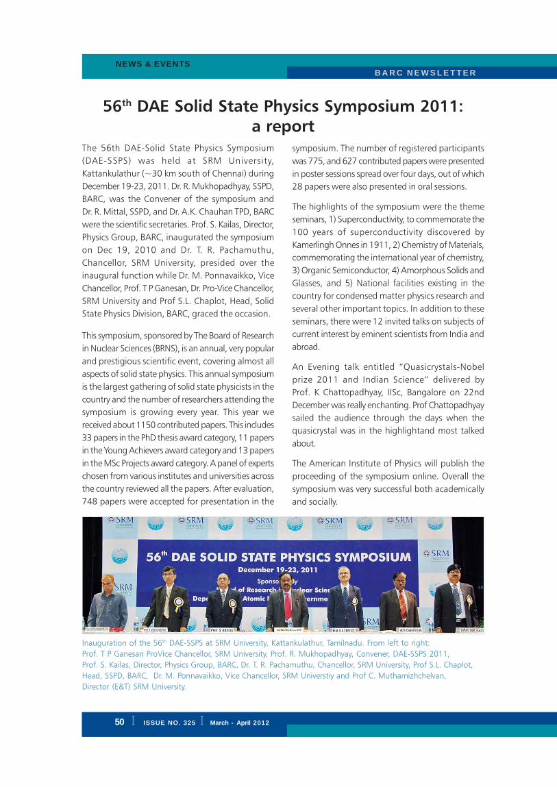
I ISSUE NO. 324 I JAN. - FEB. 2012
B A R C N E W S L E T T E RBRIEF COMMUNICATION
B A R C N E W S L E T T E R
50 I ISSUE NO. 325 I March - April 2012
NEWS & EVENTS
56th DAE Solid State Physics Symposium 2011:
a reportThe 56th DAE-Solid State Physics Symposium
(DAE-SSPS) was held at SRM University,
Kattankulathur (~30 km south of Chennai) during
December 19-23, 2011. Dr. R. Mukhopadhyay, SSPD,
BARC, was the Convener of the symposium and
Dr. R. Mittal, SSPD, and Dr. A.K. Chauhan TPD, BARC
were the scientific secretaries. Prof. S. Kailas, Director,
Physics Group, BARC, inaugurated the symposium
on Dec 19, 2010 and Dr. T. R. Pachamuthu,
Chancellor, SRM University, presided over the
inaugural function while Dr. M. Ponnavaikko, Vice
Chancellor, Prof. T P Ganesan, Dr. Pro-Vice Chancellor,
SRM University and Prof S.L. Chaplot, Head, Solid
State Physics Division, BARC, graced the occasion.
This symposium, sponsored by The Board of Research
in Nuclear Sciences (BRNS), is an annual, very popular
and prestigious scientific event, covering almost all
aspects of solid state physics. This annual symposium
is the largest gathering of solid state physicists in the
country and the number of researchers attending the
symposium is growing every year. This year we
received about 1150 contributed papers. This includes
33 papers in the PhD thesis award category, 11 papers
in the Young Achievers award category and 13 papers
in the MSc Projects award category. A panel of experts
chosen from various institutes and universities across
the country reviewed all the papers. After evaluation,
748 papers were accepted for presentation in the
symposium. The number of registered participants
was 775, and 627 contributed papers were presented
in poster sessions spread over four days, out of which
28 papers were also presented in oral sessions.
The highlights of the symposium were the theme
seminars, 1) Superconductivity, to commemorate the
100 years of superconductivity discovered by
Kamerlingh Onnes in 1911, 2) Chemistry of Materials,
commemorating the international year of chemistry,
3) Organic Semiconductor, 4) Amorphous Solids and
Glasses, and 5) National facilities existing in the
country for condensed matter physics research and
several other important topics. In addition to these
seminars, there were 12 invited talks on subjects of
current interest by eminent scientists from India and
abroad.
An Evening talk entitled “Quasicrystals-Nobel
prize 2011 and Indian Science” delivered by
Prof. K Chattopadhyay, IISc, Bangalore on 22nd
December was really enchanting. Prof Chattopadhyay
sailed the audience through the days when the
quasicrystal was in the highlightand most talked
about.
The American Institute of Physics will publish the
proceeding of the symposium online. Overall the
symposium was very successful both academically
and socially.
Inauguration of the 56th DAE-SSPS at SRM University, Kattankulathur, Tamilnadu. From left to right:
Prof. T P Ganesan ProVice Chancellor, SRM University, Prof. R. Mukhopadhyay, Convener, DAE-SSPS 2011,
Prof. S. Kailas, Director, Physics Group, BARC, Dr. T. R. Pachamuthu, Chancellor, SRM University, Prof S.L. Chaplot,
Head, SSPD, BARC, Dr. M. Ponnavaikko, Vice Chancellor, SRM Universtiy and Prof C. Muthamizhchelvan,
Director (E&T) SRM University.

ISSUE NO. 324 I JAN. - FEB. 2012 I
B A R C N E W S L E T T E R BRIEF COMMUNICATION
B A R C N E W S L E T T E RNEWS & EVENTS
ISSUE NO. 325 I March - April 2012 I 51
Ninth Supervisory Training Programme on
“Radioactive Waste Management”: a Report
The Ninth supervisory training programme on
Radioactive Waste Management was designed,
formulated and conducted at BARC, Trombay during
January 9th to 20th, 2012, for the supervisors who
are associated in waste generation in various plants /
facilities / research labs and also those who are
engaged in waste management. This training
programme covered various aspects of Radioactive
Waste Management, radiation protection and
industrial & fire safety. The training programme was
carried out by way of classroom lectures,
demonstrations and visits to various plant / facilities
at Trombay such as Plutonium Plant, Waste
Immobilization Plant, RSMS, ETP and Dhruva reactor.
Faculty members were invited from Trombay, Tarapur
and Kalpakkam sites of NRG and NRB and from AFD,
ROD, IHSS, Tombay Dispensary, Fire Station, etc. to
deliver the lectures. The topics covered were
radioactive waste management of different types of
waste; matrices for immobilization and their quality
assurance; near surface disposal systems; deep
geological disposal; radiation, industrial and fire
safety; radiation monitoring; health physics; first aid;
ventilation aspects; off-gas cleaning; aspects of
remote handling; waste management database; future
projects related to waste management; process
instrumentation and control; plant process flow-
sheets of various waste management plants;
minimization of waste; etc. Few more subjects such
as regulation, dose apportionment, waste assaying,
waste compaction, various remote gadgets, special
techniques for separation of useful isotopes from
waste, cold crucible technology, etc, were also
covered.
During the inaugural programme, on 9th January
2012, Shri P. N. Patil welcomed the gathering.
Shri R.G. Yeotikar, Officer-in-Charge, Training, NRG
Inaugural function of Ninth Supervisory Training Programme. Mr. R.G. Yeotikar, officer-in-charge, training, Nuclear
Recycle Group & organizer of this training programme; is giving brief account of the training programme and the
selection of the subjects. Others on the dais (from left to right) are Mr. P. K. Wattal, Head, PSDD;
Mr. S. Basu, Chief Executive, NRB; Mr. Kanwar Raj, Head, WMD and Mr. K.N.S. Nair, Head, TDD

I ISSUE NO. 324 I JAN. - FEB. 2012
B A R C N E W S L E T T E RBRIEF COMMUNICATION
B A R C N E W S L E T T E R
52 I ISSUE NO. 325 I March - April 2012
NEWS & EVENTS
and organizer of this programme, introduced the
syllabus of the programme and explained the
importance of the selected subjects. Shri K.N.S. Nair,
Head, TDD; Shri Kanwar Raj, Head, Waste
Management Division; Shri P. K. Wattal, Head, Process
Development Division and Shri S. Basu, Chief
Executive, Nuclear Recycle Board, addressed the
trainees and emphasized importance of training and
its usefulness in updating knowledge in various
aspects of radioactive waste management.
Shri Kanwar Raj, in his invited talk, presented the
philosophy of radioactive waste management &
indicated that we should also consider waste as a
source of wealth. He appealed to the participants to
follow simple methods and practices (i)to minimize
the wastes, (ii) to segregate the wastes and (iii)to
reuse and recycle the waste so that they help waste
managers directly or indirectly for reduction of waste
volume and enhancement of safety of environment
and of future generation. Vote of thanks was given
by Shri P. Patange.
The Valedictory Function of this training programme
was held on 20th January 2012 and was presided
over by Shri Kanwar Raj, Head, Waste Management
Division. Shri K.M. Singh, Plant Superintendent, WMF,
Trombay, and other senior officers attended the
valedictory function. During this valedictory function
a feed back session was arranged for participants
from all the sites. Shri R. G. Yeotikar, Officer-in-
Charge, Training, answered and responded to this
feedback. Thereafter the certificates were awarded
to all the participants.
Photograph of participants of Ninth Supervisory Training Programme on
Radioactive Waste Management
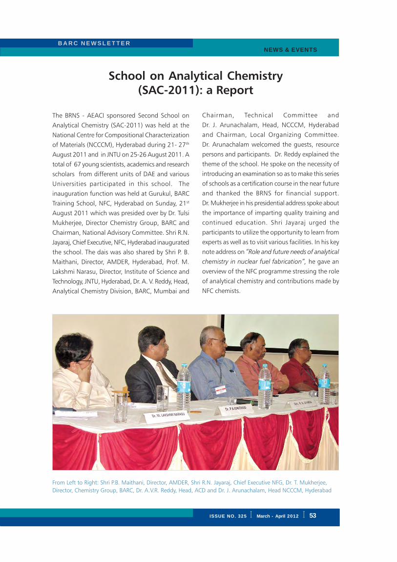
ISSUE NO. 324 I JAN. - FEB. 2012 I
B A R C N E W S L E T T E R BRIEF COMMUNICATION
B A R C N E W S L E T T E RNEWS & EVENTS
ISSUE NO. 325 I March - April 2012 I 53
School on Analytical Chemistry
(SAC-2011): a Report
The BRNS - AEACI sponsored Second School on
Analytical Chemistry (SAC-2011) was held at the
National Centre for Compositional Characterization
of Materials (NCCCM), Hyderabad during 21- 27th
August 2011 and in JNTU on 25-26 August 2011. A
total of 67 young scientists, academics and research
scholars from different units of DAE and various
Universities participated in this school. The
inauguration function was held at Gurukul, BARC
Training School, NFC, Hyderabad on Sunday, 21st
August 2011 which was presided over by Dr. Tulsi
Mukherjee, Director Chemistry Group, BARC and
Chairman, National Advisory Committee. Shri R.N.
Jayaraj, Chief Executive, NFC, Hyderabad inaugurated
the school. The dais was also shared by Shri P. B.
Maithani, Director, AMDER, Hyderabad, Prof. M.
Lakshmi Narasu, Director, Institute of Science and
Technology, JNTU, Hyderabad, Dr. A. V. Reddy, Head,
Analytical Chemistry Division, BARC, Mumbai and
Chairman, Technical Committee and
Dr. J. Arunachalam, Head, NCCCM, Hyderabad
and Chairman, Local Organizing Committee.
Dr. Arunachalam welcomed the guests, resource
persons and participants. Dr. Reddy explained the
theme of the school. He spoke on the necessity of
introducing an examination so as to make this series
of schools as a certification course in the near future
and thanked the BRNS for financial support.
Dr. Mukherjee in his presidential address spoke about
the importance of imparting quality training and
continued education. Shri Jayaraj urged the
participants to utilize the opportunity to learn from
experts as well as to visit various facilities. In his key
note address on “Role and future needs of analytical
chemistry in nuclear fuel fabrication”, he gave an
overview of the NFC programme stressing the role
of analytical chemistry and contributions made by
NFC chemists.
From Left to Right: Shri P.B. Maithani, Director, AMDER, Shri R.N. Jayaraj, Chief Executive NFG, Dr. T. Mukherjee,
Director, Chemistry Group, BARC, Dr. A.V.R. Reddy, Head, ACD and Dr. J. Arunachalam, Head NCCCM, Hyderabad

I ISSUE NO. 324 I JAN. - FEB. 2012
B A R C N E W S L E T T E RBRIEF COMMUNICATION
B A R C N E W S L E T T E R
54 I ISSUE NO. 325 I March - April 2012
NEWS & EVENTS
Dr. Mukherjee released a monograph on sample
preparation, prepared by scientific staff of NCCCM.
Inaugural function ended with vote of thanks by
Dr. A. C. Sahayam, Secretary, Local Organizing
Committee.
The course consisted of lectures in the morning
session and experiments in the afternoon sessions. A
wide variety of lectures were delivered by experts
and experiments belonging to various aspects of
analytical chemistry and environmental analytical
chemistry were conducted by Colleagues from
NCCCM and JNTU. The topics covered were trace
and ultra trace analysis, QA/QC, accreditation and
reference materials, importance of organic and
inorganic mass spectrometry, neutron activation
analysis and ion beam analysis, spectrometric
techniques such as atomic absorption and ICP-OES,
chromatographic techniques, electroanalytical
chemistry, thermal analysis, X-Ray fluorescence,
environmental analysis and elemental speciation in
analytical chemistry. Lectures and experiments
related to environmental analysis and statistical
treatment of data and uncertainties in analytical
measurements were held at Centre for Environment,
JNTU, Hyderabad during 25, 26 August 2011.
Experiments namely i) multi elemental analysis by
ICP-OES, ii) determination of Hg in environmental
samples using CVAAS, iii) determination of Cr
(VI) using Ion Chromatograph, iv) determination of
Cd using ELCAD and v) ion bean analyses using
tandem accelerator were conducted in NCCM. The
experiments vi) Analysis of gaseous samples for
Methane, CO2 and Hydrogen in GC, vii) Analysis of
organics in waste waters and contaminated soils by
GC MS, viii) measurement of COD, DO and BOD in
waters and waste water sample and ix) determination
of Ammonia in water samples were conducted at
JNTU. Five Special lectures were delivered by
(i) Dr. Tulsi Mukherjee on “safety in chemical
laboratories”, (ii) Shri. N. Saibaba, ACE, NFC on
“Activities of NFC” on 21-08-2011, (iii) Shri. G. V. S.
Hemantha Rao, DCE, NFC on “Nuclear Material
Accounting (NUMAC)” on 22-08-11, (iv) Shri. P. S.
Parihar, AD (operations), AMDER on “The role of
AMD in nuclear power program” on 23-08-11 and
(v) Shri Narayana Rao, ECIL, Hyderabad on “Analytical
Instrumentation” on 27-08-11.
Valedictory function was chaired by Dr. J.
Arunachalm and spoke about the importance of the
school, its utility etc. Dr. A. V. R Reddy delivered the
valedictory lecture on “Atoms for peace” giving an
emphasis to DAE’s three stage programme. All the
participants were given certificates by Dr. J.
Arunachalam. Vote of thanks was proposed by
Dr. R. K. Singhal, Secretary, SAC.

ISSUE NO. 324 I JAN. - FEB. 2012 I
B A R C N E W S L E T T E R BRIEF COMMUNICATION
B A R C N E W S L E T T E RNEWS & EVENTS
ISSUE NO. 325 I March - April 2012 I 55
Report on DAE-BRNS National Workshop on
Materials Chemistry (Functional Materials)
(NWMC 2011- FUNMAT)
The DAE-BRNS National Workshop on Materials
Chemistry (Functional Materials) (NWMC 2011-
FUNMAT), organized by the Chemistry Division and
Society for Materials Chemistry, was held at BARC
during 7-8 December, 2011. The workshop received
an overwhelming response from various academic
and R&D institutes, across the country. About 200
registered participants from different disciplines such
as chemistry, physics and materials science attended
the technical sessions. The workshop was convened
with 17 invited talks, spanning across diverse topics
relevant to advanced functional materials. Some of
the topics were magnetic materials, glasses and glass
ceramics, hydrogen production and storage, synthetic
materials chemistry, electrical materials, sensors, soft
materials, optical materials etc. The topics were
selected based upon recent upsurge in the research
and development in materials relevant to advanced
technologies, energy production, sensors and devices,
nuclear waste management, health sciences etc.
The workshop began with a keynote address by
Dr. V. C. Sahni, DAE Homi Bhabha Chair Professor
and former Director, RRCAT, Indore. In his inaugural
address Dr. Sahni mentioned about new innovations
in several key areas of materials science and
emphasized the importance of multidisciplinary
research in materials development programmes.
Molecule based magnetic materials for future
electronic applications and multifunctional magnetic
particles for drug delivery were some of the key
functional materials discussed during the workshop.
Invited speakers presented their research work and
perspectives on several functional materials for diverse
applications such as glass formation and applications
in nuclear waste management, materials development
for hydrogen generation and storage, high purity
materials preparation for electronics, synthetic
chemistry for tuning crystal structure and function.
Application of novel experimental tools like dielectric
spectroscopy and impedance spectroscopy in
characterizing materials for super-ionic conduction,
multiferroics etc. were discussed. Development of
thin film materials for sensors of gases and
biomolecules, design of soft materials via self
assembly, optical materials for solid state lighting
etc. were also discussed.
The workshop concluded with a valedictory function
chaired by Dr. T. Mukherjee, Director Chemistry
Group. Many participants gave their feedback about
the workshop and appreciated the diversity and
interdisciplinary nature in the topics. The workshop
offered an excellent platform for young researchers
to discuss among various delegates and experts in
the field. This could lead ways to strengthen their
research by interdisciplinary and multi-institutional
cooperation.
From Left: Dr. P. A. Hassan, Dr. T. Mukherjee, Dr. V. C. Sahni and Dr. D. Das

I ISSUE NO. 324 I JAN. - FEB. 2012
B A R C N E W S L E T T E RBRIEF COMMUNICATION
B A R C N E W S L E T T E R
56 I ISSUE NO. 325 I March - April 2012
NEWS & EVENTS
“Status of Vitrification Technology for
Treatment of High Level Liquid Waste”:
Report of a Theme Meeting
A one day theme meeting on “Status of Vitrification
Technology for Treatment of High Level Liquid Waste”
was arranged by the Nuclear Recycle Board in
coordination with the Board of Research in Nuclear
Sciences (BRNS) at BARC, Tarapur on February 22,
2012. The objective of the theme meeting was to
summarize all recent developments on high level
waste management with respect to technology,
matrix and process development on a single platform.
Experts in the field briefed the participants about the
recent developments in the field. About 175 delegates
from different units of BARC participated in the
deliberations. Following topics were covered in the
theme meeting:
• Development and deployment of various
vitrification technologies
• Processing of HLW using various vitrification
techniques
• Recovery of valuables, Development of actinide
partitioning and ceramic matrices
• Challenges in treatment of HLW arising from
reprocessing AHWR and FBR spent fuels.
• Remote control aspects in HLW management
and its transportation.
• HAW management aspects at Integrated Recycle
projects
Shri. S.D. Misra, Director Nuclear Recycle Group
inaugurated the theme meeting in the presence of
Shri S. Basu, Chief Executive, Nuclear Recycle Board.
Shri Kanwar Raj, Head Waste Management Division
gave a key note address covering the overview of
development of Vitrification technology in India.
Dr. C.P. Kaushik briefed about the challenges in waste
management with respect to the HLW arising from
reprocessing of AHWR and FBR spent fuels.
Ms. Smitha Manohar gave a broad idea about the
need of actinide partitioning as well as recovery of
various valuables from HLW. Shri Y. Kulkarni, CS,
TNRPO shared his practical experience on the Joule
Heated Ceramic Melter for processing of HLW and
its decommissioning features. Dr. G. Sugilal gave a
brief introduction to futuristic vitrification technology
making use of the cold crucible method. Shri K.K.
Haldar gave an overview of the Integrated Recycle
projects for HLW management of Nuclear Recycle
Board. Various aspects of remote control in
management of HLW and transportation were
covered by Shri. K.M. Singh. Plant Superintendent,
WMD, BARC, Trombay.
Shri S.D. Misra, Director, NRG giving the inaugural address. On the dais from left to right: Shri Y. Kulkarni, Chief
Superintendent Tarapur based Nuclear Recycle Plant operations, Shri S. Basu, Chief Executive, NRB, Shri G.J. Prasad,
Director,NFG and Shri Kanwar Raj, Head, WMD.

ISSUE NO. 324 I JAN. - FEB. 2012 I
B A R C N E W S L E T T E R BRIEF COMMUNICATION
B A R C N E W S L E T T E R
ISSUE NO. 325 I March - April 2012 I iii
BARC Scientists Honoured
Name of the Scientist : Tulsi Mukherjee
Director, Chemistry Group
Conferred : Lifetime Contribution Award in Free Radical Research
Conferred by : Society for Free Radical Research, India, at SFRR Conference,
Kolkata during 12-14, Feb, 2012
Name of the Scientist : K. Srinivas
Architecture & Civil Engineering Division
Award : 9th Vishveshvaraiya Construction Excellence Award, 2012 for outstanding
contribution in Engineering & Infrastructure Sector
Presented at : Inaugural Session of the International Conference “Rail Asia 2012”, Mumbai,
4th May, 2012.
Name of the Scientist : A.K. Tyagi
Chemistry Group
Conferred : CRSI CNR Rao National Prize in Chemical Sciences (2012) for significant
and outstanding contributions in Chemical Sciences
Conferred by : Chemical Research Society of India, Bengaluru at the 14th CRSI
National Symposium in Chemistry at NIIST, Thiruvananthapuram,
during Feb. 3-5, 2012
Name of the Scientists : S. Mukhopadhyay, L. S. Danu, D.C. Biswas, P.N. Prashanth,
A. Goswami, A. Chatterjee and R.K. Choudhury
Title of the Paper : Yrast and near-yrast spectroscopy of Neutron-rich fission fragments using
Thermal Neutrons from Reactor
Award : First Prize in Poster Presentation
Presented at : DAE Symposium on Nuclear Physics at Department of Nuclear Physics,
Andhra University, Visakhapatnam from December 26-30, 2011
Name of the Scientist : H.N. Ghosh
Radiation & Photochemistry Division
Conferred : CRSI Bronze Medal (2012) for outstanding contribution in
Chemical Research
Conferred by : Chemical Research Society of India, Bengaluru at the 14th CRSI National
Symposium in Chemistry at NIIST, Thiruvananthapuram,
during Feb. 3-5, 2012