brief introduction - ecsdownload.ecs.com.cn/dlfileecs/manual/mb/h81h3-i/h81h3-i v1.0 low.pdf ·...
TRANSCRIPT

H81H3-I USER MANUAL 1
Brief Introduction
CPU
Specifications
• Intel® H81 ChipsetChipset
• Dual-channel DDR3 memory architecture• 2 x 240-pin DDR3 DIMM sockets support up to 16 GB• Supports DDR3 1600/1333 MHz DDR3 SDRAM
Memory
• 1 x PCI Express x16 Gen2 slot• 1 x Mini PCI Express x1 slot
• Supported by Intel® H81 Express Chipset- 2 x Serial ATA 6Gb/s devices, 2 x Serial ATA 3Gb/s devices
ExpansionSlots*
Storage
• 1 x PS/2 keyboard and PS/2 mouse connectors• 1 x DVI port* (or HDMI port)• 1 x VGA port• 4 x USB 2.0 ports* (or 2 x USB 3.0 ports and 2 x USB 2.0 ports)• 1 x RJ45 LAN connector• 1 x Audio port (1x Line in, 1x Line out, 1x Mic_in Rear)
Rear Panel I/O
• Realtek RTL8111G Giga LAN- 10/100/1000 Fast Ethernet Controller- Wake-on-LAN and remote wake-up support
• LGA1150 socket for 4th Generation Intel® CoreTM Family/Pentium/Celeron Processors
Note: Please go to ECS website for the latest CPU support list.
• 1 x 24-pin ATX Power Supply connector• 1 x 4-pin 12V Power connector• 1 x 4-pin CPU_FAN connector• 1 x 4-pin SYS_FAN connector• 2 x USB 2.0 headers support additional four USB 2.0 ports• 1 x USB 3.0 header supports additional two USB 3.0 ports
(Co-lay two USB 3.0 ports at the rear panel)*• 2 x Serial SATA 6Gb/s connectors• 2 x Serial SATA 3Gb/s connectors• 1 x COM header• 1 x Case open header• 1 x Front Panel audio header• 1 x Front Panel switch/LED header• 1 x Speaker header• 1 x ME_UNLOCK header• 1 x CLR_CMOS jumper
Internal I/OConnectors &Headers
• VIA VT1705CP- 6 Channel High Definiton Audio Codec- Compliant with HD audio specification
Audio
LAN
Note: *PCIe SPEC will be changed with Intel latest CPU SPEC.
Note: *Please take the actual motherboard as standard.
Note: *If there are dual USB 3.0 ports at the rear panel, the USB 3.0header duo to Intel H81 chipset SPEC just supports two USB3.0 ports. Please take the actual motherboard as standard.

H81H3-I USER MANUAL2
QR Code for the complete manual downloadon ECS website: http://www.ecs.com.tw
• AMI BIOS with 64Mb SPI Flash ROM- Supports Plug and Play, STR(S3)/STD(S4)- Supports Hardware Monitor- Supports ACPI & DMI- Supports Audio, LAN, can be disabled in BIOS- F7 hot key for boot up devices option
- Supports Dual Display (depends on display output)- Supports EZ BIOS (1024 x 768 resolution, GUI UEFI)- Supports Multi-language- Supports AC’97/HD Audio auto detect (default)
System BIOS
• Mini-ITX 170mm x 170mm
- Supports Pgup clear CMOS Hotkey (Has PS2 KB Model only)
Form Factor
• ECS Exclusive AP: Supports eBLU*1/eDLU/eSF*1
• 3rd Party Bundled software: Cyberlink Media Suite*2/NortonAnti Virus*2/Muzee*2
AP/BundledSoftwareSupport
Note: *1Microsoft .NET Framework 3.5 is required.
*2Free bundle software including ECS DVD: Cyberlink MediaSuite/Norton Anti Virus/Muzee
Specifications are subject to change without notice.
H81H3-I USER MANUAL 3
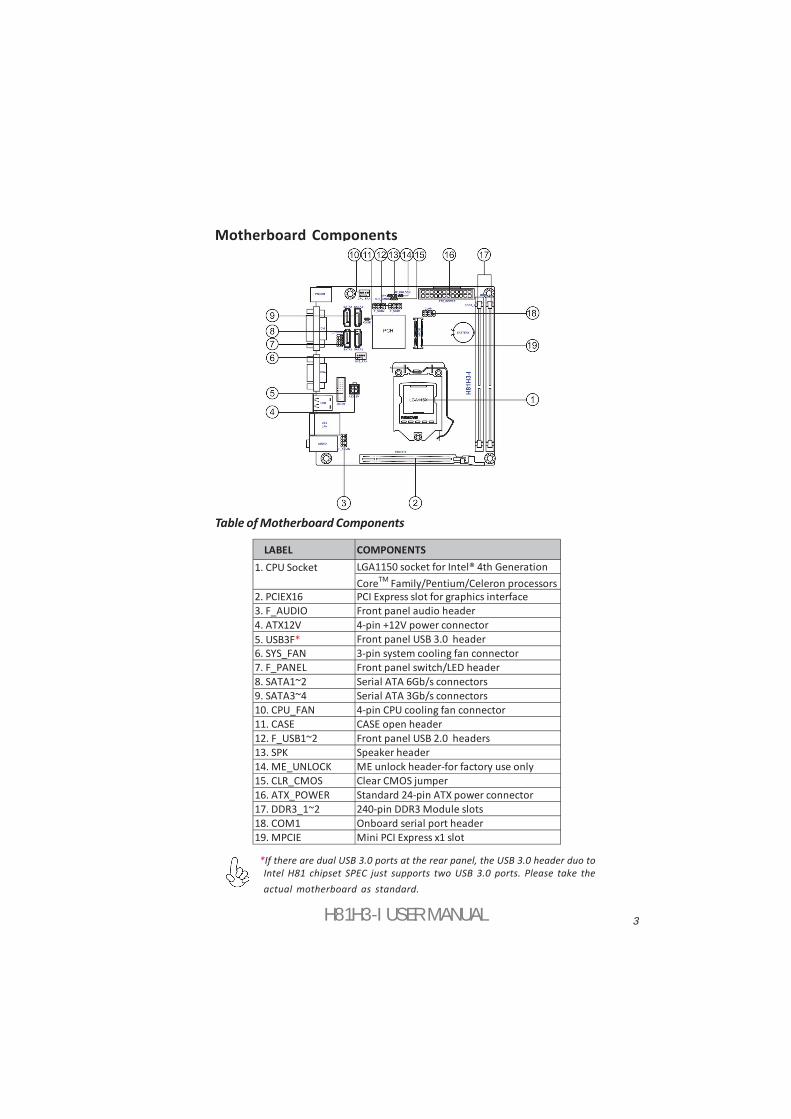
Motherboard Components
Table of Motherboard Components
LABEL COMPONENTSLGA1150 socket for Intel® 4th Generation CoreTM Family/Pentium/Celeron processors
2. PCIEX16 PCI Express slot for graphics interface3. F_AUDIO Front panel audio header4. ATX12V 4-pin +12V power connector5. USB3F* Front panel USB 3.0 header6. SYS_FAN 3-pin system cooling fan connector7. F_PANEL Front panel switch/LED header8. SATA1~2 Serial ATA 6Gb/s connectors9. SATA3~4 Serial ATA 3Gb/s connectors10. CPU_FAN 4-pin CPU cooling fan connector11. CASE CASE open header12. F_USB1~2 Front panel USB 2.0 headers13. SPK Speaker header14. ME_UNLOCK ME unlock header-for factory use only15. CLR_CMOS Clear CMOS jumper16. ATX_POWER Standard 24-pin ATX power connector17. DDR3_1~2 240-pin DDR3 Module slots18. COM1 Onboard serial port header19. MPCIE Mini PCI Express x1 slot
1. CPU Socket
*If there are dual USB 3.0 ports at the rear panel, the USB 3.0 header duo toIntel H81 chipset SPEC just supports two USB 3.0 ports. Please take theactual motherboard as standard.
H81H3-I USER MANUAL
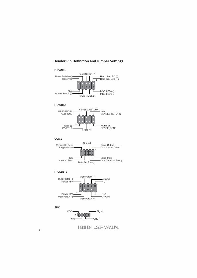
F_AUDIO
19
F_USB1~2
1
1
COM1
Key
PORT 1L PORT 1R
PORT 2RSENSE_SEND
AUD_GNDPRESENCE#
SENSE1_RETURNKeySENSE2_RETURN
KEY
NC
KEY
1
F_PANEL
Hard disk LED (-)Hard disk LED (+)
Reset Switch (-)Reset Switch (+)
Reserved
Power Switch (-)Power Switch (+)
MSG LED (+)MSG LED (-)
Ground
Power +5V
Power +5V
GroundUSB Port A (-)
USB Port B (-)
USB Port A (+)
USB Port B (+)
Serial OutputData Carrier Detect
Serial Input
Ring Indicator
Data Terminal ReadyClear to Send
Request to Send
Data Set Ready
Ground
PORT 2L
4
SPK
1VCC Signal
Key GND
5H81H3-I USER MANUAL
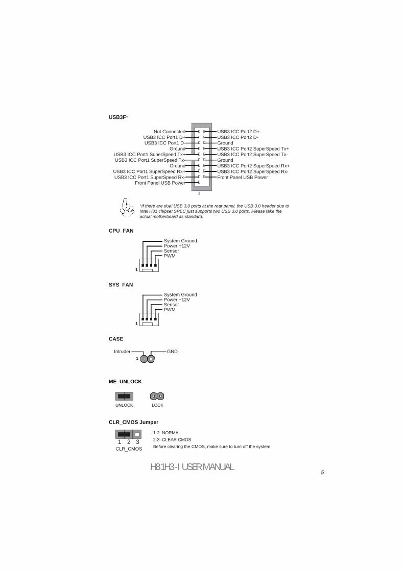
UNLOCK
1 2
1Intruder GND
CASE
CLR_CMOS Jumper
ME_UNLOCK
1-2: NORMAL
Before clearing the CMOS, make sure to turn off the system.
*If there are dual USB 3.0 ports at the rear panel, the USB 3.0 header duo to Intel H81 chipset SPEC just supports two USB 3.0 ports. Please take the actual motherboard as standard.
CLR_CMOS3
CPU_FAN
LOCK
2-3: CLEAR CMOS
SYS_FAN
SensorPWM
System GroundPower +12V
1
SensorPWM
System GroundPower +12V
1
USB3F*
1
Front Panel USB PowerFront Panel USB Power
GroundGround
USB3 ICC Port1 D+Not Connected
GroundGroundUSB3 ICC Port1 D-
USB3 ICC Port2 D+USB3 ICC Port2 D-
USB3 ICC Port1 SuperSpeed Rx-USB3 ICC Port2 SuperSpeed Rx-USB3 ICC Port1 SuperSpeed Rx+USB3 ICC Port2 SuperSpeed Rx+
USB3 ICC Port1 SuperSpeed Tx-USB3 ICC Port2 SuperSpeed Tx-USB3 ICC Port1 SuperSpeed Tx+USB3 ICC Port2 SuperSpeed Tx+
H81H3-I USER MANUAL6
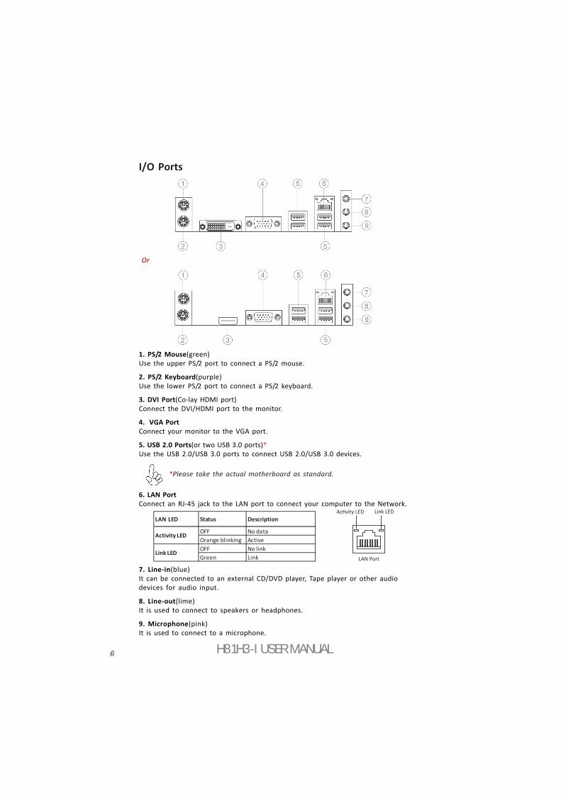
I/O Ports
1. PS/2 Mouse(green)Use the upper PS/2 port to connect a PS/2 mouse.
2. PS/2 Keyboard(purple)Use the lower PS/2 port to connect a PS/2 keyboard.
3. DVI Port(Co-lay HDMI port)Connect the DVI/HDMI port to the monitor.
4. VGA PortConnect your monitor to the VGA port.
5. USB 2.0 Ports(or two USB 3.0 ports)*Use the USB 2.0/USB 3.0 ports to connect USB 2.0/USB 3.0 devices.
6. LAN PortConnect an RJ-45 jack to the LAN port to connect your computer to the Network.
7. Line-in(blue)It can be connected to an external CD/DVD player, Tape player or other audiodevices for audio input.
8. Line-out(lime)It is used to connect to speakers or headphones.
9. Microphone(pink)It is used to connect to a microphone.
LAN LED Status Description
OFF No dataOrange blinking ActiveOFF No linkGreen Link
Activity LED
Link LED
Link LED
LAN Port
Or
*Please take the actual motherboard as standard.
7
Eng
lish
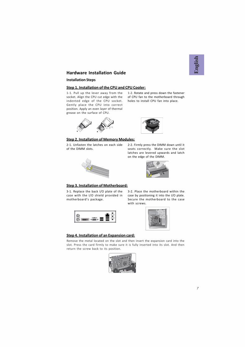
Step 1. Installation of the CPU and CPU Cooler:
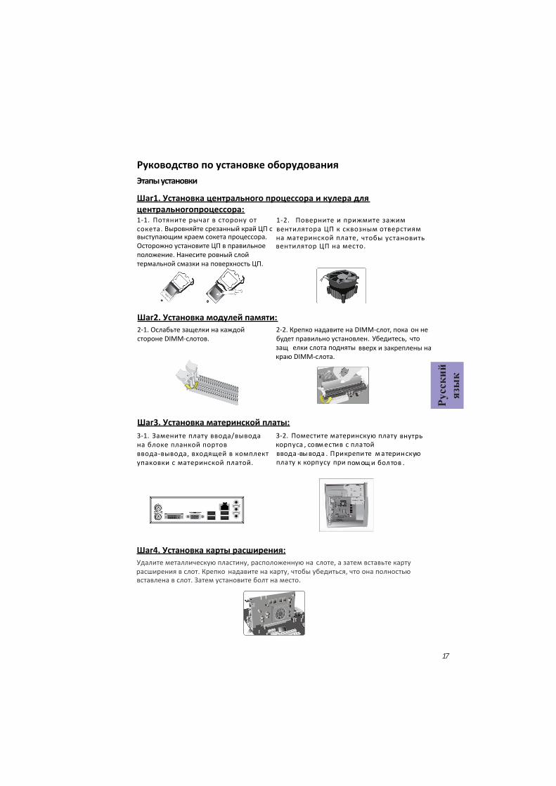
Hardware Installation GuideInstallation Steps
1-1. Pull up the lever away from thesocket. Align the CPU cut edge with theindented edge of the CPU socket.Gently place the CPU into correctposition. Apply an even layer of thermalgrease on the surface of CPU.
Step 2. Installation of Memory Modules:2-1. Unfasten the latches on each sideof the DIMM slots.
Step 3. Installation of Motherboard:3-1. Replace the back I/O plate of thecase with the I/O shield provided inmotherboard’s package.
1-2. Rotate and press down the fastenerof CPU fan to the motherboard throughholes to install CPU fan into place.
2-2. Firmly press the DIMM down until itseats correctly. Make sure the slotlatches are levered upwards and latchon the edge of the DIMM.
3-2. Place the motherboard within thecase by positioning it into the I/O plate.Secure the motherboard to the casewith screws.
Step 4. Installation of an Expansion card:Remove the metal located on the slot and then insert the expansion card into theslot. Press the card firmly to make sure it is fully inserted into its slot. And thenreturn the screw back to its position.
8
English
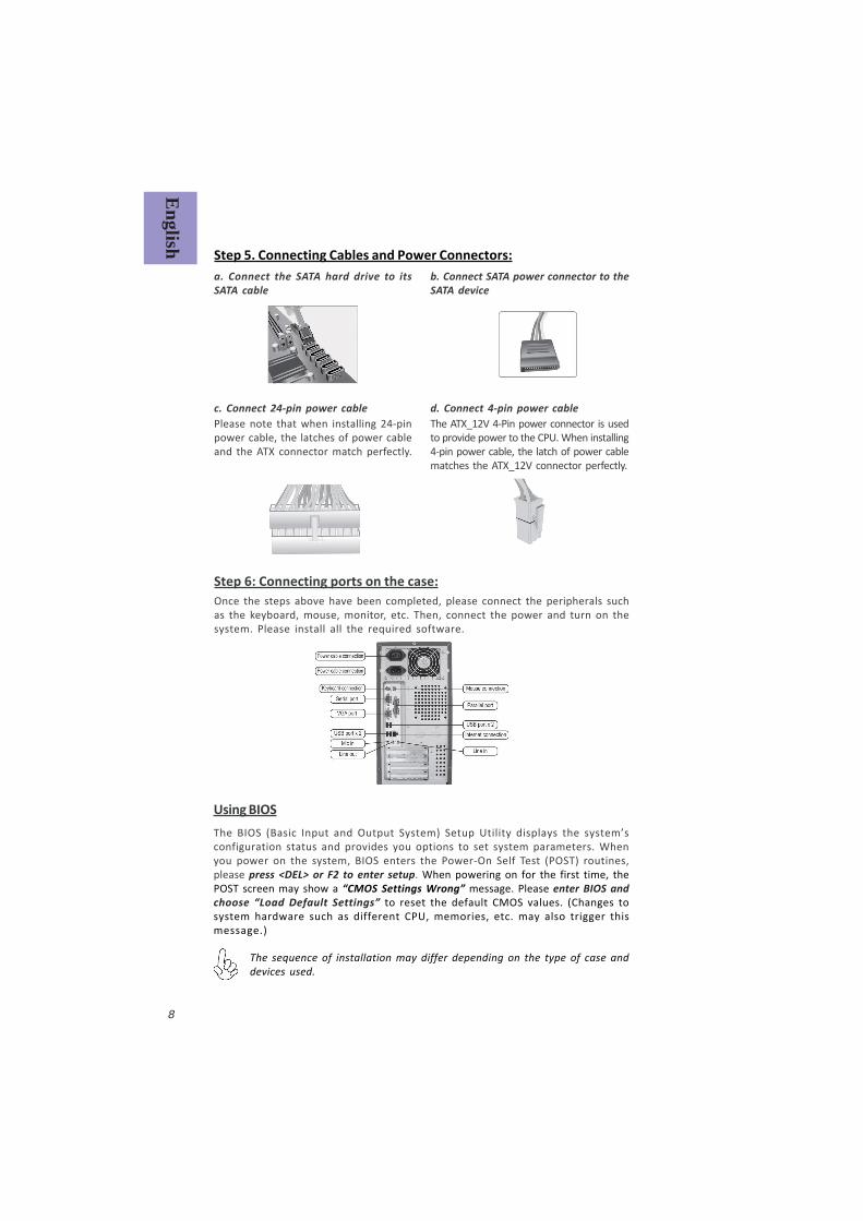
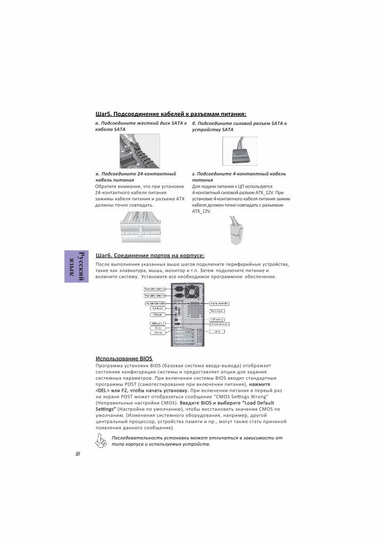
Step 5. Connecting Cables and Power Connectors:
c. Connect 24-pin power cableThe ATX_12V 4-Pin power connector is usedto provide power to the CPU. When installing4-pin power cable, the latch of power cablematches the ATX_12V connector perfectly.
b. Connect SATA power connector to theSATA device
Once the steps above have been completed, please connect the peripherals suchas the keyboard, mouse, monitor, etc. Then, connect the power and turn on thesystem. Please install all the required software.
Step 6: Connecting ports on the case:
a. Connect the SATA hard drive to itsSATA cable
d. Connect 4-pin power cablePlease note that when installing 24-pinpower cable, the latches of power cableand the ATX connector match perfectly.
The sequence of installation may differ depending on the type of case anddevices used.
Using BIOSThe BIOS (Basic Input and Output System) Setup Utility displays the system’sconfiguration status and provides you options to set system parameters. Whenyou power on the system, BIOS enters the Power-On Self Test (POST) routines,please press <DEL> or F2 to enter setup. When powering on for the first time, thePOST screen may show a “CMOS Settings Wrong” message. Please enter BIOS andchoose “Load Default Settings” to reset the default CMOS values. (Changes tosystem hardware such as different CPU, memories, etc. may also trigger thismessage.)
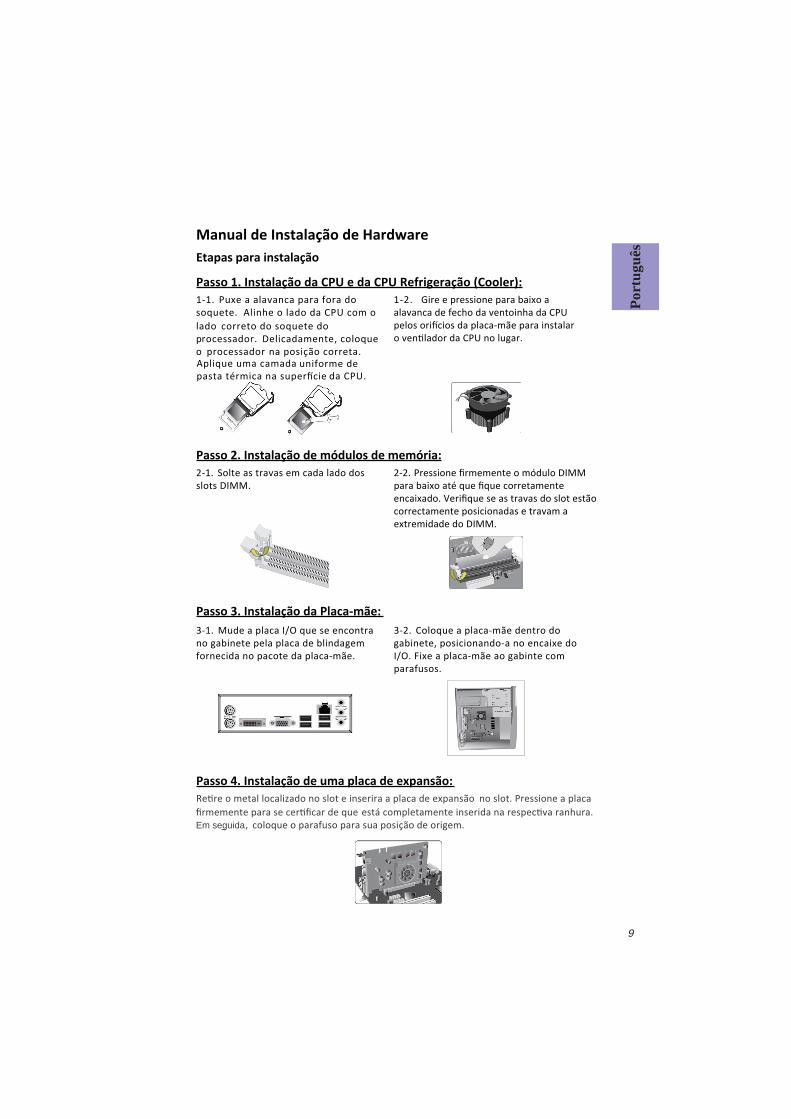
Passo 1. Instalação da CPU e da CPU Refrigeração (Cooler):
Manual de Instalação de HardwareEtapas para instalação
1-1. Puxe a alavanca para fora do soquete.
Passo 2. Instalação de módulos de memória:2-1. Solte as travas em cada lado dos slots DIMM.
Passo 3. Instalação da Placa-mãe:3-1. Mude a placa I/O que se encontra no gabinete pela placa de blindagem fornecida no pacote da placa-mãe.
Alinhe o lado da CPU com o lado correto do soquete do processador. Delicadamente, coloqueo processador na posição correta. Aplique uma camada
da CPU.
2-2. Pressione rmemente o módulo DIMM para baixo até que que corretamente encaixado. Veri que se as travas do slot estão correctamente posicionadas e travam a extremidade do DIMM.
3-2. Coloque a placa-mãe dentro do gabinete, posicionando-a no encaixe do I/O. Fixe a placa-mãe ao gabinte com parafusos.
1-2. Gire e pressione para baixo a alavanca de fecho da ventoinha da CPU
Passo 4. Instalação de uma placa de expansão:
coloque o parafuso para sua posição de origem.Em seguida
Port
uguê
s
9
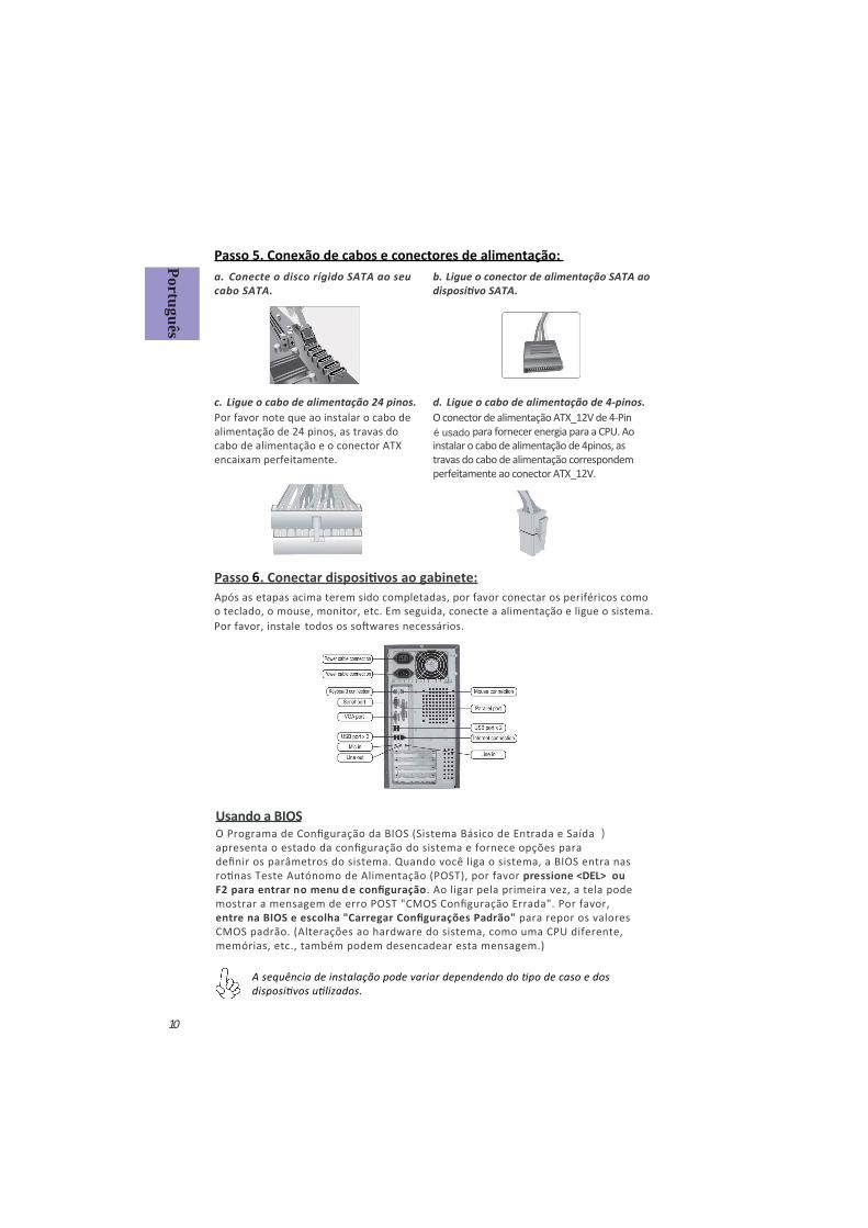
Passo 5. Conexão de cabos e conectores de alimentação:
c. Ligue o cabo de alimentação 24 pinos. O conector de alimentação ATX_12V de 4-Pin
instalar o cabo de alimentação de 4pinos, as travas do cabo de alimentação correspondem perfeitamente ao conector ATX_12V.
b. Ligue o conector de alimentação SATA ao a. Conecte o disco rígido SATA ao seu cabo SATA.
d. Ligue o cabo de alimentação de 4-pinos.Por favor note que ao instalar o cabo de alimentação de 24 pinos, as travas do cabo de alimentação e o conector ATX encaixam perfeitamente.
é usado
Português
Usando a BIOSO Programa de Con guração da BIOS (Sistema Básico de Entrada e Saída ) apresenta o estado da con guração do sistema e fornece opções para de nir os parâmetros do sistema. Quando você liga o sistema, a BIOS entra nas
pressione <DEL> ou F2 para entrar no menu d e con guração. Ao ligar pela primeira vez, a tela pode mostrar a mensagem de erro POST "CMOS Con guração Errada". Por favor, entre na BIOS e escolha "Carregar Con gurações Padrão" para repor os valores CMOS padrão. (Alterações ao hardware do sistema, como uma CPU diferente, memórias, etc., também podem desencadear esta mensagem.)
10
Após as etapas acima terem sido completadas, por favor conectar os periféricos como o teclado, o mouse, monitor, etc. Em seguida, conecte a alimentação e ligue o sistema.
Por favor, instale
6

1-1.
2-1. DIMM
CPU CPU
1-2. CPU CPU
2-2. DIMM
3-1. I/O
I/O
3-2. I/O
CPU CPU
11
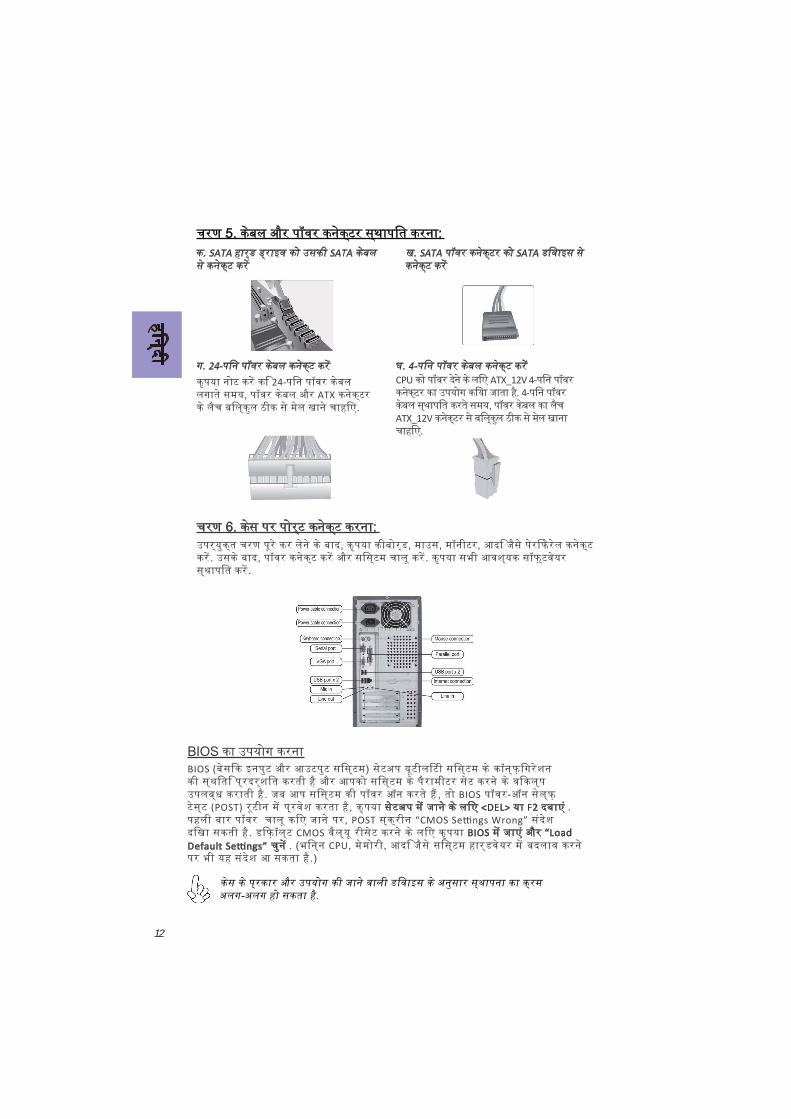
24-CPU ATX_12V 4-
4-
ATX_12V
SATA SATA SATA SATA
4-24-
ATX
12
BIOS (
BIOS(POST)
POSTCMOS
CPUBIOS
<DEL> F2
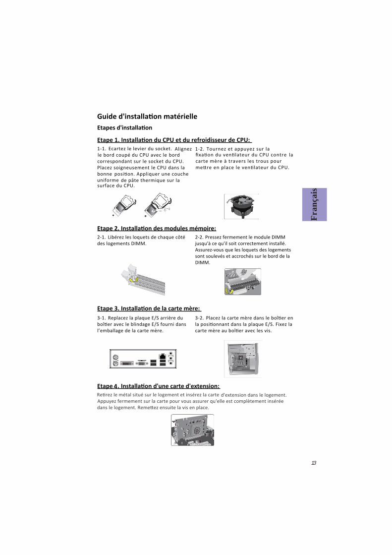
1-1. Ecartez le levier du socket.
2-1. Libérez les loquets de chaque côté des logements DIMM.
3-1. Replacez la plaque E/S arrière du
l’emballage de la carte mère.
Alignez le bord coupé du CPU avec le bord correspondant sur le socket du CPU. Placez soigneusement le CPU dans la
bonne de pâte thermique sur la
surface du CPU.
1-2. Tournez et appuyez sur la
2-2. Pressez fermement le module DIMM jusqu'à ce qu'il soit correctement installé. Assurez-vous que les loquets des logements sont soulevés et accrochés sur le bord de la DIMM.
3-2.
la carte mère à travers les trous pour
Fran
çais
d'extension dans le logement. Appuyez fermement sur la carte pour vous assurer qu'elle est complètement insérée
4
13
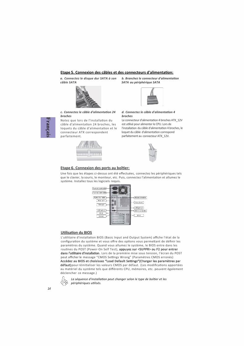
c. broches
connecteur ATX_12V.
b. au périphérique SATA
a. Connectez le disque dur SATA à son câble SATA
d. broches
connecteur ATX correspondent parfaitement.
Français
14
5
Une fois que les étapes ci-dessus ont été e ectuées, connectez les périphériques tels que le clavier, la et allumez le système. Installez tous les logiciels requis.
6
paramètres du système. Quand vous allumez le système, le BIOS entre dans les appuyez sur <SUPPR> ou F2 pour entrer
dans . Lors de la première mise sous tension, l'écran du POST peut a cher le
Accédez au BIOS et pour
du système tels que di érents CPU, mémoires, etc. peuvent également déclencher ce message.)

1-1. Lösen Sie den Hebel vom CPU-Sockel.
2-1. Lösen Sie die Verriegelungen an beiden Seiten der DIMM-Steckplätze.
Kunststo abdeckung und richten Sie die Kerbe der CPU mit der entsprechenden Stelle des CPU-Sockels aus. Legen Sie die
Tragen Sie eine erbsengroße Menge der
Ober äche der CPU auf.
2-2. Drücken Sie das DIMM-Speichermodul
sitzt. Drücken Sie die Verriegelungen an den Seiten des Speichermoduls nach oben und prüfen Sie, ob diese im DIMM-Speichermodul
ATX-Blende (I/O-Schild) des Gehäuses und verwenden Sie die ATX-Blende, die
wurde.
3-2. Richten Sie die Anschlussseite der der
ATX-Blende im Gehäuse aus und
mit den Schrauben am Gehäuse.
Deu
tsch
15
1-2. Lösen Sie durch eine Drehung die Pushpins des CPU-Kühlers und richten Sie diese mit den
entsprechenden Löchern aus und drücken Sie die
Pushpins nach unten bis sie einrasten.
Metall hinten am Gehäuse, wo der zu verwendende Steckplatz sic et und stecken Sie die Erweiterungskarte in den Steckplatz. Prüfen Sie ob die Kontakte der Erweiterungskarte
die Erweiterungskarte mit der Schraube mit der die
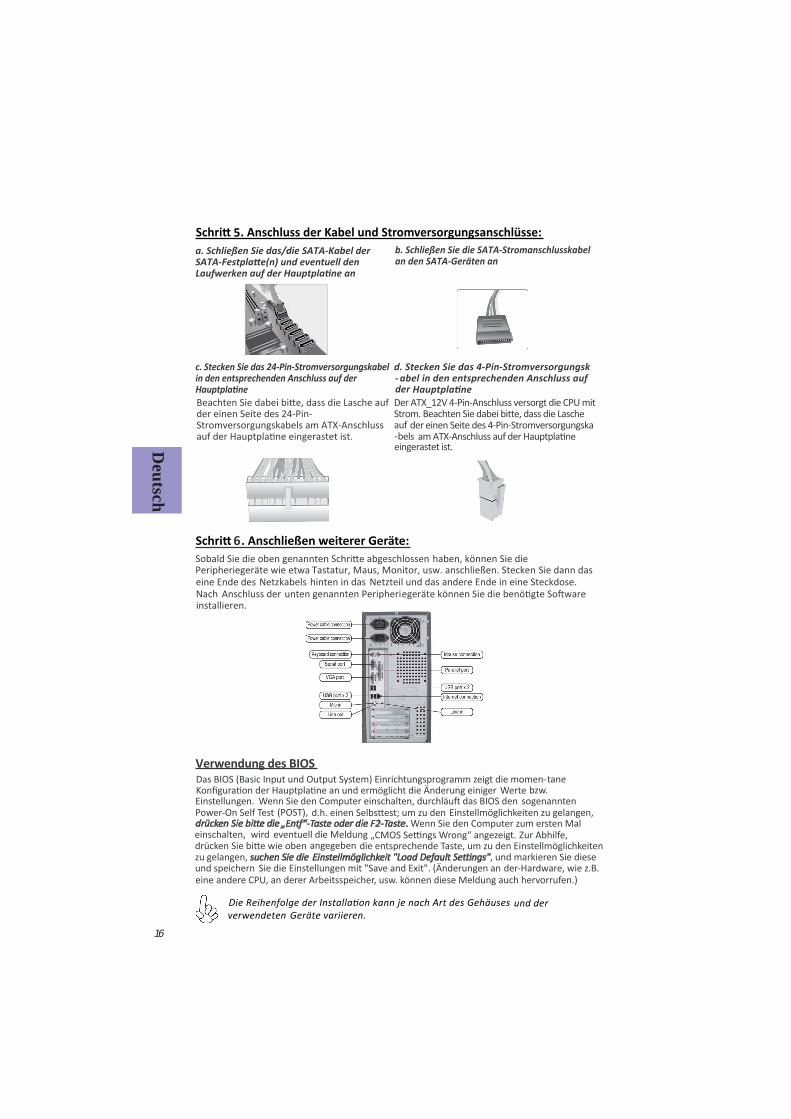
c. Stecken Sie das 24-Pin-Stromversorgungskabel in den entsprechenden Anschluss auf der
Der ATX_12V 4-Pin-Anschluss versorgt die CPU mit
der einen Seite des 4-Pin-Stromversorgungska-bels
b. Schließen Sie die SATA-Stromanschlusskabel an den SATA-Geräten an
a. Schließen Sie das/die SATA-Kabel der
d. Stecken Sie das 4-Pin-Stromversorgungskabel in- den entsprechenden Anschluss auf
der
der einen Seite des 24-Pin-Stromversorgungskabels am ATX-Anschluss
Deutsch
16
Peripheriegeräte wie etwa haben, können Sie die
Tastatur, Maus, Monitor, usw. anschließen. Stecken Sie dann das Netzkabels hinten in das Netzteil und das andere Ende in eine Steckdose.
Anschluss der unten genannten Peripheriegeräte können
6
und der verwendeten Geräte variieren.
Verwendung des BIOSDas BIOS (Basic Input und Output System) Einrichtungsprogramm zeigt die momen-
Einstellmöglichkeiten zu gelangen, . Wenn Sie den Computer zum ersten Mal
einschalten, wird eeventuell di Meldung die entsprechende Taste, um zu den Einstellmöglichkeiten
zu gelangen, suchen Sie die , und markieren Sie diese und speichern Sie die Einstellungen mit "Save and Exit". (Änderungen an der-Hardware, wie z.B. eine andere CPU, an derer Arbeitsspeicher, usw. können diese Meldung auch hervorrufen.)
eine Ende des Nach
1
1-1. .
33-1. /
- ,
.
1-2.
, .
3-2. , - . .
17
, , . , ,
. .
5. :
. 24-
. SATA SATA
a. SATA SATA
. 4-
, 24-
ATX .
4- ATX_12V.
4-
ATX_12V.
18
, , , . .
. .
6. :
BIOS BIOS ( - )
. BIOS POST ( ),
<DEL > F2, .
( CMOS). BIOS “Load Default ( ), CMOS
. ( , , , .,
).
.
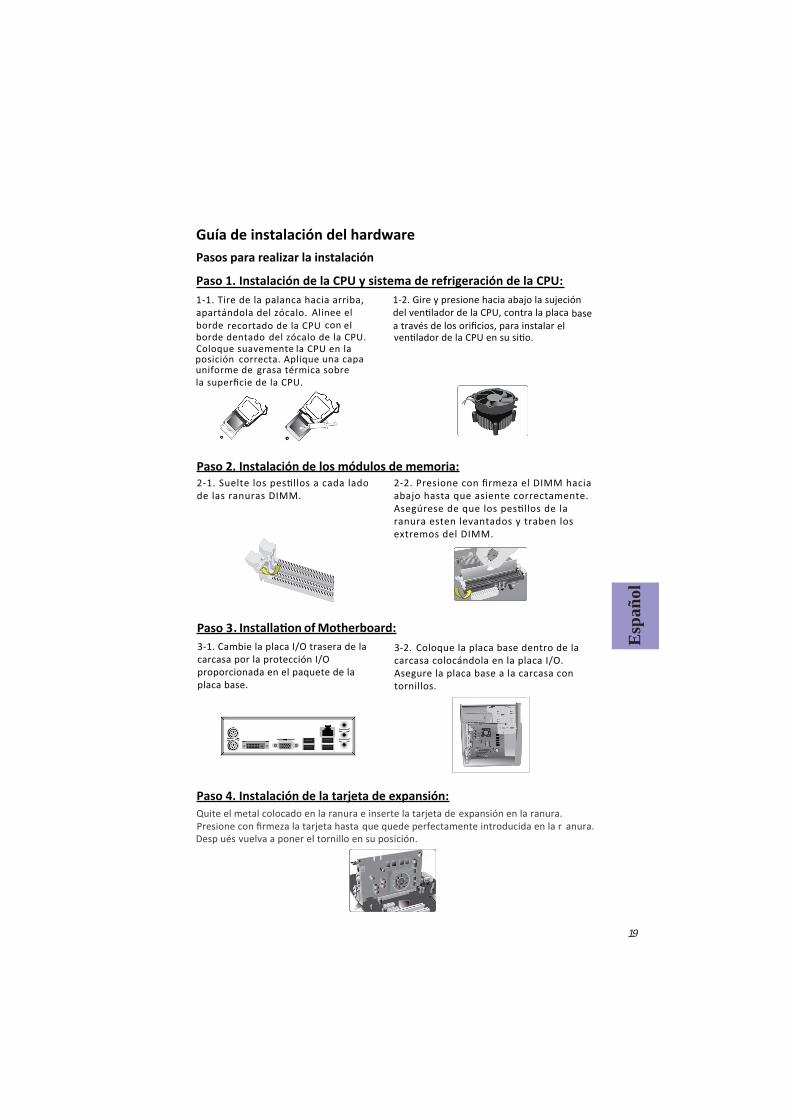
Paso 1. Instalación de la CPU y sistema de refrigeración de la CPU:
Guía de instalación del hardwarePasos para realizar la instalación
Paso 2. Instalación de los módulos de memoria:
. of Motherboard:
3-2. Coloque la placa base dentro de la carcasa colocándola en la placa I/O. Asegure la placa base a la carcasa con tornillos.
1-1. Tire de la palanca hacia arriba, apartándola del zócalo. Alinee el borde recortado de la CPU con el
borde dentado del zócalo de la CPU. Coloque suavemente la CPU en la
posición correcta. Aplique una capa uniforme de grasa térmica sobre la super cie de la CPU.
1-2. Gire y presione hacia abajo la sujeción base
a través de los ori cios, para instalar
de las ranuras DIMM.2-2. Presione con rmeza el DIMM hacia abajo hasta que asiente correctamente.
ranura esten levantados y traben los extremos del DIMM.
3-1. Cambie la placa I/O trasera de la carcasa por la protección I/O proporcionada en el paquete de la placa base.
Esp
añol
19
Paso 4. Instalación de la tarjeta de expansión:Quite el metal colocado en la ranura e inserte la tarjeta de expansión en la ranura. Presione con rmeza la tarjeta hasta que quede perfectamente introducida en la rDesp
anura.ués vuelva a poner el tornillo en su posición.
Paso 3
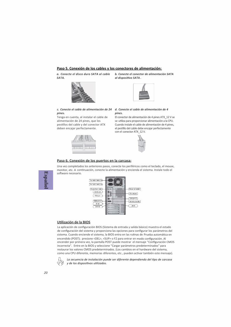
Paso 5. Conexión de los cables y los conectores de alimentación:
c. Conecte el cable de alimentación de 24 pines.
b. Conecte el conector de alimentación SATA a. Conecte el disco duro SATA al cableSATA.
d. Conecte el cable de alimentación de 4 pines.
.
Tenga en cuenta, al instalar el cable de alimentación de 24 pines, que los
deben encajar perfectamente.
El conector de alimentación de 4 pines ATX_12 V se se Cuando instale el cable de alimentación de 4 pines,
conector ATX_12 V.
Español
20
Paso 6. Conexión de los puertos en la carcasa:Una vez completados los anteriores pasos, conecte los periféricos como el teclado, el mouse, monitor, etc. A
estado
mensaje incorrecta".
como una CPU diferente, memorias
el
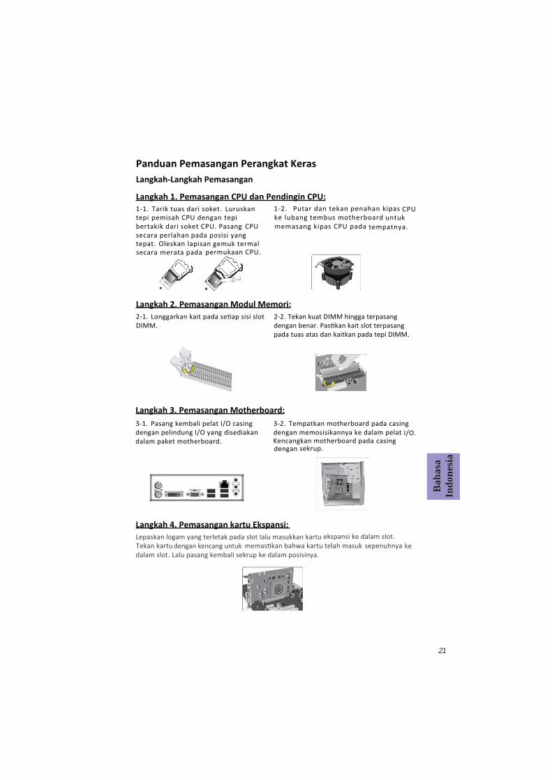
Langkah 1. Pemasangan CPU dan Pendingin CPU:
Panduan Pemasangan Perangkat KerasLangkah-Langkah Pemasangan
1-1. Tarik tuas dari soket.
Langkah 2. Pemasangan Modul Memori:2-1. DIMM.
Langkah 3. Pemasangan Motherboard:3-1. Pasang kembali pelat I/O casing dengan pelindung I/O yang disediakan dalam paket motherboard.
Luruskan tepi pemisah CPU dengan tepi bertakik dari soket CPU. Pasang CPU secara perlahan pada posisi yang tepat. Oleskan lapisan gemuk termal
secara merata pada permukaan CPU.
1-2. Putar dan tekan penahan kipas
CPU ke lubang tembus motherboard untuk memasang kipas CPU pada tempatnya.
2-2. Tekan kuat DIMM hingga terpasang
pada tuas atas dan kaitkan pada tepi DIMM.
3-2. Tempatkan motherboard pada casingdengan memosisikannya ke dalam pelat I/O. Kencangkan motherboard pada casing dengan sekrup.
Bah
asa
Indo
nesi
a
21
Langkah 4. Pemasangan kartu Ekspansi:Lepaskan logam yang terletak pada slot lalu masukkan kartu
dengan kencang untuk ahwa kartu telah masuk sepenuhnya ke dalam slot. Lalu pasang kembali sekrup ke dalam posisinya.
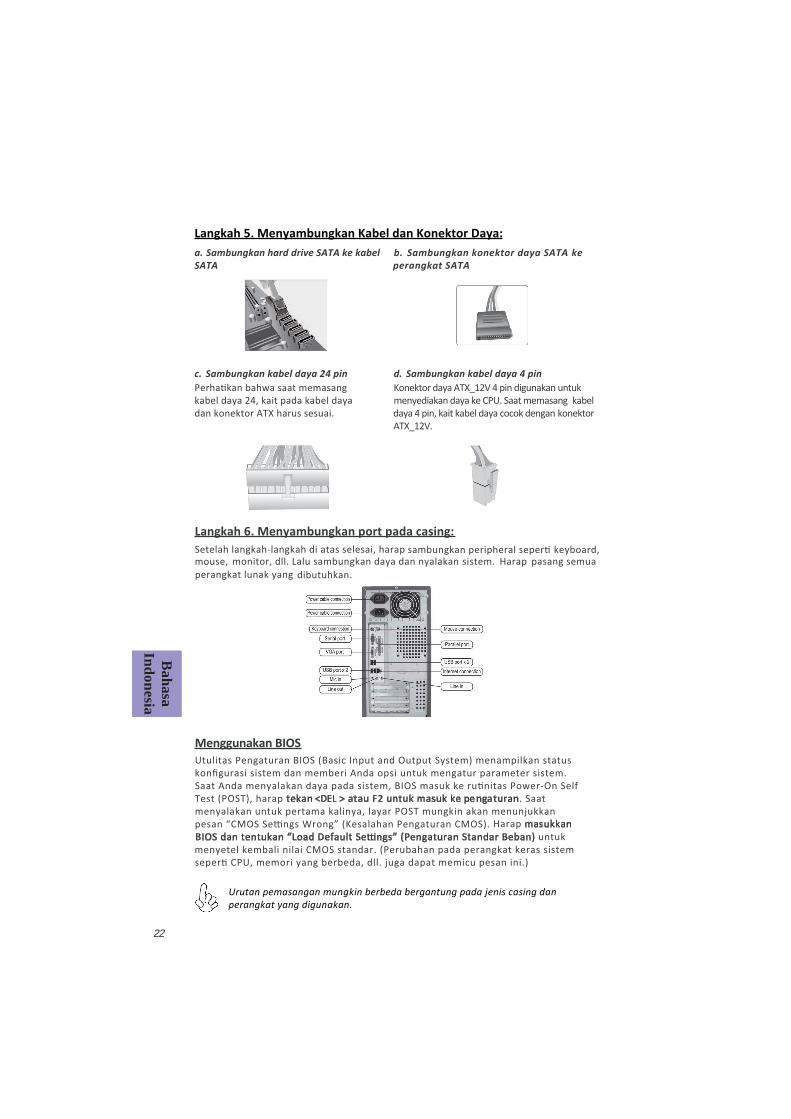
Langkah 5. Menyambungkan Kabel dan Konektor Daya:
c. Sambungkan kabel daya 24 pinKonektor daya ATX_12V 4 pin digunakan untuk menyediakan daya ke CPU. Saat memasang kabel daya 4 pin, kait kabel daya cocok dengan konektor ATX_12V.
a. Sambungkan hard drive SATA ke kabel SATA
b. Sambungkan konektor daya SATA ke perangkat SATA
d. Sambungkan kabel daya 4 pin
kabel daya 24, kait pada kabel daya dan konektor ATX harus sesuai.
Bahasa
Indonesia
22
Setelah langkah-langkah di atas selesai, harap monitor, dll. Lalu sambungkan daya dan nyalakan sistem. Harap pasang semua
perangkat lunak yang dibutuhkan.
Langkah 6. Menyambungkan port pada casing:
Menggunakan BIOSUtulitas Pengaturan BIOS (Basic Input and Output System) menampilkan status kon gurasi sistem dan memberi Anda opsi untuk mengatur parameter sistem.
Test (POST), harap tekan <DEL > atau F2 untuk masuk ke pe ngaturan. Saat menyalakan untuk pertama kalinya, layar POST mungkin akan menunjukkan
untuk
icu pesan ini.)
Harap masukkan
menyetel kembali nilai CMOS standar. (Perubahan
Urutan pemasangan mungkin berbeda bergantung pada jenis casing dan perangkat yang digunakan.
23
يةرب
لعا
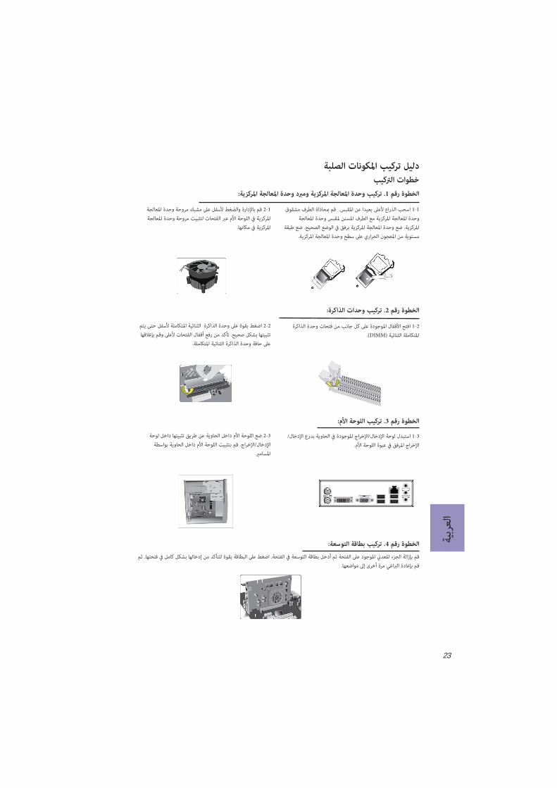
دليل تركيب املكونات الصلبة خطوات الرتكيب
الخطوة رقم 1. تركيب وحدة املعالجة املركزية ومربد وحدة املعالجة املركزية:
1-1وحدة املعالجة املركزية مع الطرف املسنن ملقبس وحدة املعالجة
املركزية. ضع وحدة املعالجة املركزية برفق يف الوضع الصحيح. ضع طبقة مستوية من املعجون الحراري عىل سطح وحدة املعالجة املركزية.
1-2 قم باإلدارة والضغط ألسفل عىل مشبك مروحة وحدة املعالجةاملركزية يف اللوحة األم عرب الفتحات لتثبيت مروحة وحدة املعالجة
املركزية يف مكانها.
الخطوة رقم 2. تركيب وحدات الذاكرة:
2-1 افتح األقفال املوجودة عىل كل جانب من فتحات وحدة الذاكرة .(DIMM) املتكاملة الثنائية
2-2 اضغط بقوة عىل وحدة الذاكرة الثنائية املتكاملة ألسفل حتى يتم تثبيتها بشكل صحيح. تأكد من رفع أقفال الفتحات ألعىل وقم بإغالقها
عىل حافة وحدة الذاكرة الثنائية املتكاملة.
الخطوة رقم 3. تركيب اللوحة األم:
3-1 استبدل لوحة اإلدخال/اإلخراج املوجودة يف الحاوية بدرع اإلدخال/اإلخراج املرفق يف عبوة اللوحة األم.
3-2 ضع اللوحة األم داخل الحاوية عن طريق تثبيتها داخل لوحة اإلدخال/اإلخراج. قم بتثبيت اللوحة األم داخل الحاوية بواسطة
الخطوة رقم 4. تركيب بطاقة التوسعة:
قم بإعادة الرباغي مرة أخرى إىل مواضعها.
24
العربية
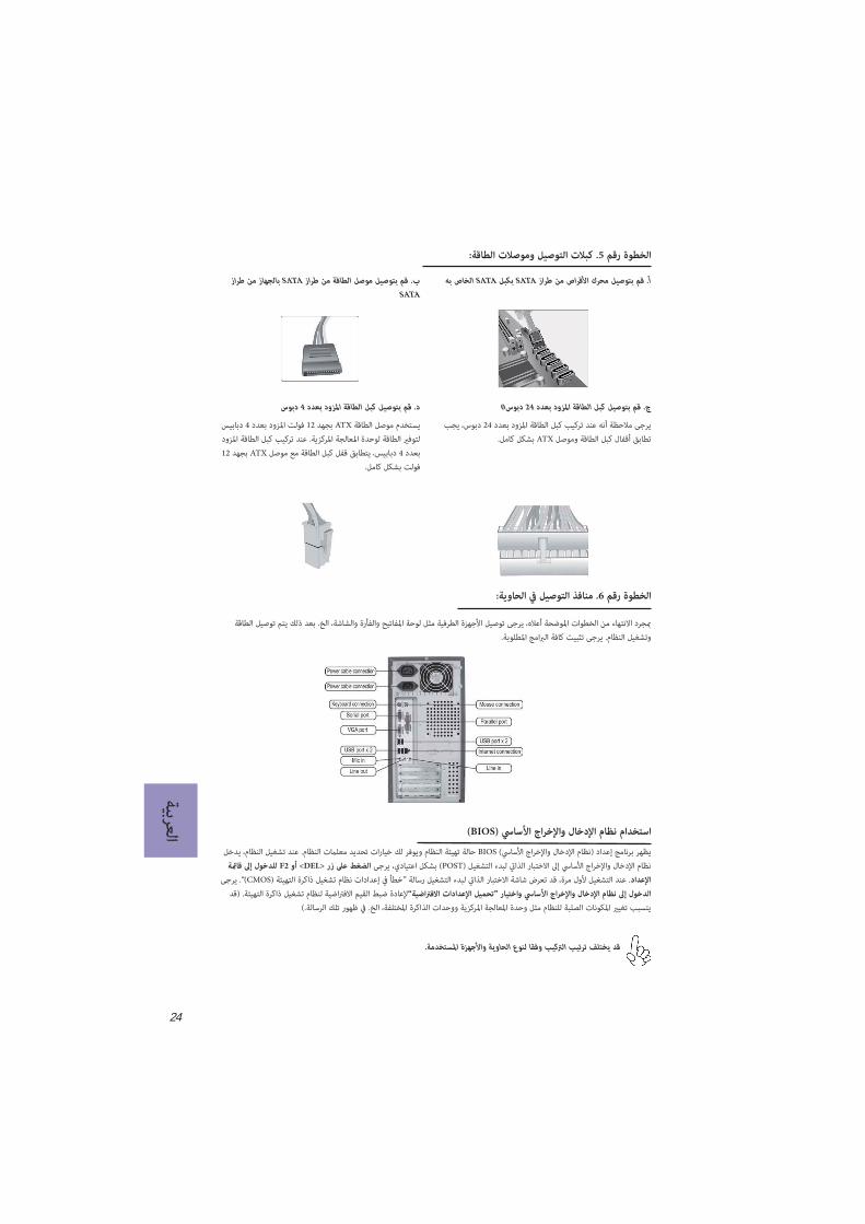
أ. قم بتوصيل محرك األقراص من طراز SATA بكبل SATA الخاص به
الخطوة رقم 5. كبالت التوصيل وموصالت الطاقة:
ج. قم بتوصيل كبل الطاقة املزود بعدد 24 دبوس0
يرجى مالحظة أنه عند تركيب كبل الطاقة املزود بعدد 24 دبوس، يجب تطابق أقفال كبل الطاقة وموصل ATX بشكل كامل.
د. قم بتوصيل كبل الطاقة املزود بعدد 4 دبوس
يستخدم موصل الطاقة ATX بجهد 12 فولت املزود بعدد 4 دبابيس لتوفري الطاقة لوحدة املعالجة املركزية. عند تركيب كبل الطاقة املزود بعدد 4 دبابيس، يتطابق قفل كبل الطاقة مع موصل ATX بجهد 12
فولت بشكل كامل.
ب. قم بتوصيل موصل الطاقة من طراز SATA بالجهاز من طراز SATA
الخطوة رقم 6. منافذ التوصيل يف الحاوية:
مبجرد االنتهاء من الخطوات املوضحة أعاله، يرجى توصيل األجهزة الطرفية مثل لوحة املفاتيح والفأرة والشاشة، الخ. بعد ذلك يتم توصيل الطاقة وتشغيل النظام. يرجى تثبيت كافة الربامج املطلوبة.
يظهر برنامج إعداد (نظام اإلدخال واإلخراج األسايس) BIOS حالة تهيئة النظام ويوفر لك خيارات تحديد معلامت النظام. عند تشغيل النظام، يدخل نظام اإلدخال واإلخراج األسايس إىل االختبار الذايت لبدء التشغيل (POST) بشكل اعتيادي، يرجى الضغط عىل زر <DEL> أو F2 للدخول إىل قامئة
اإلعداد. عند التشغيل ألول مرة، قد تعرض شاشة االختبار الذايت لبدء التشغيل رسالة ”خطأ يف إعدادات نظام تشغيل ذاكرة التهيئة (CMOS)“. يرجى الدخول إىل نظام اإلدخال واإلخراج األسايس واختيار ”تحميل اإلعدادات االفرتاضية“إلعادة ضبط القيم االفرتاضية لنظام تشغيل ذاكرة التهيئة. (قد
يتسبب تغيري املكونات الصلبة للنظام مثل وحدة املعالجة املركزية ووحدات الذاكرة املختلفة، الخ. يف ظهور تلك الرسالة.)
(BIOS) استخدام نظام اإلدخال واإلخراج األسايس
قد يختلف ترتيب الرتكيب وفقا لنوع الحاوية واألجهزة املستخدمة.
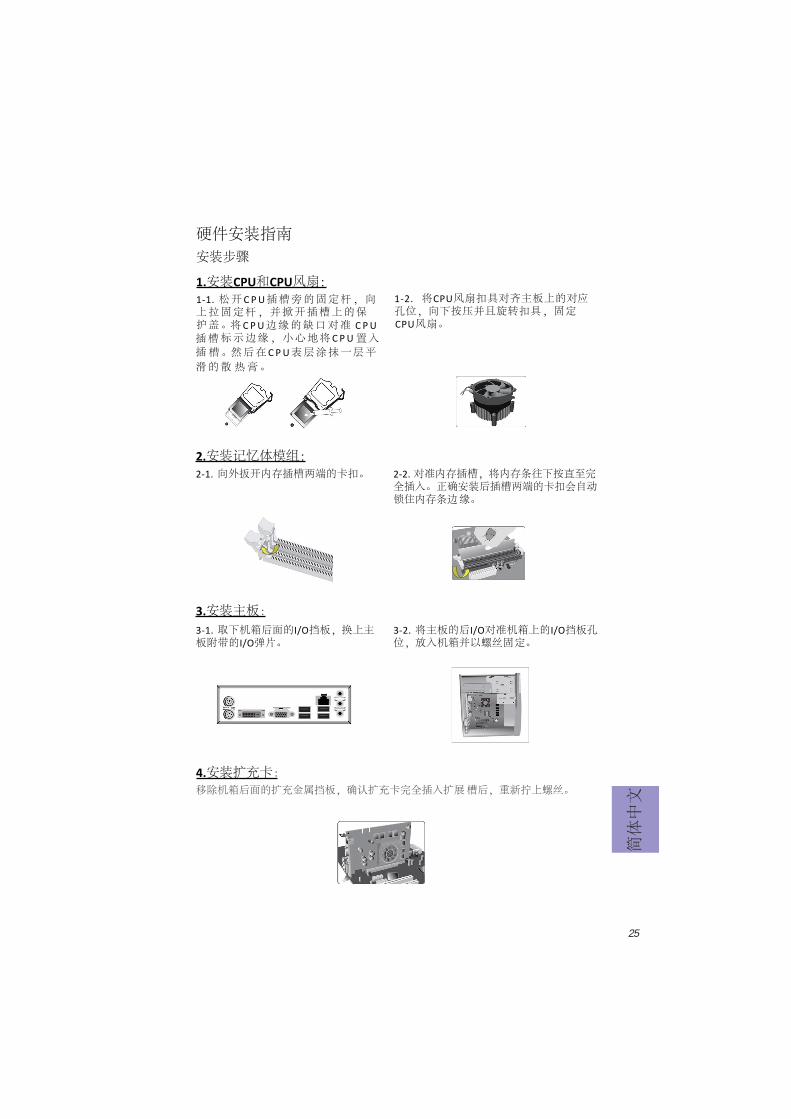
1.安装CPU和CPU风扇:
硬件安装指南安装步骤
1-1. 松开 C P U插槽旁的固定杆,向上拉固定杆,并掀开插槽上的保护盖。
2.安装记忆体模组:2-1. 向外扳开内存插槽两端的卡扣。
3.3-1. 取下机箱后面的I/O挡板,换上主板附带的I/O弹片。
将 C P U边缘的缺口对准 C P U插槽标示边缘,小心地将 C P U插
置入槽。
滑的然后在 C P U表层涂抹一层平散热膏。
1-2. 将CPU风扇扣具对齐主板上的对应孔位,向下按压并且旋转扣具,固定CPU风扇。
2-2. 对准内存插槽,将内存条往下按直至完全插入。正确安装后插槽两端的卡扣会自动锁住内存条边缘。
3-2. 将主板的后I/O对准机箱上的I/O挡板孔位,放入机箱并以螺丝固定。
4.移除机箱后面的扩充金属挡板,确认扩充卡完全插入扩展槽后,重新拧上螺丝。
简体中文
25
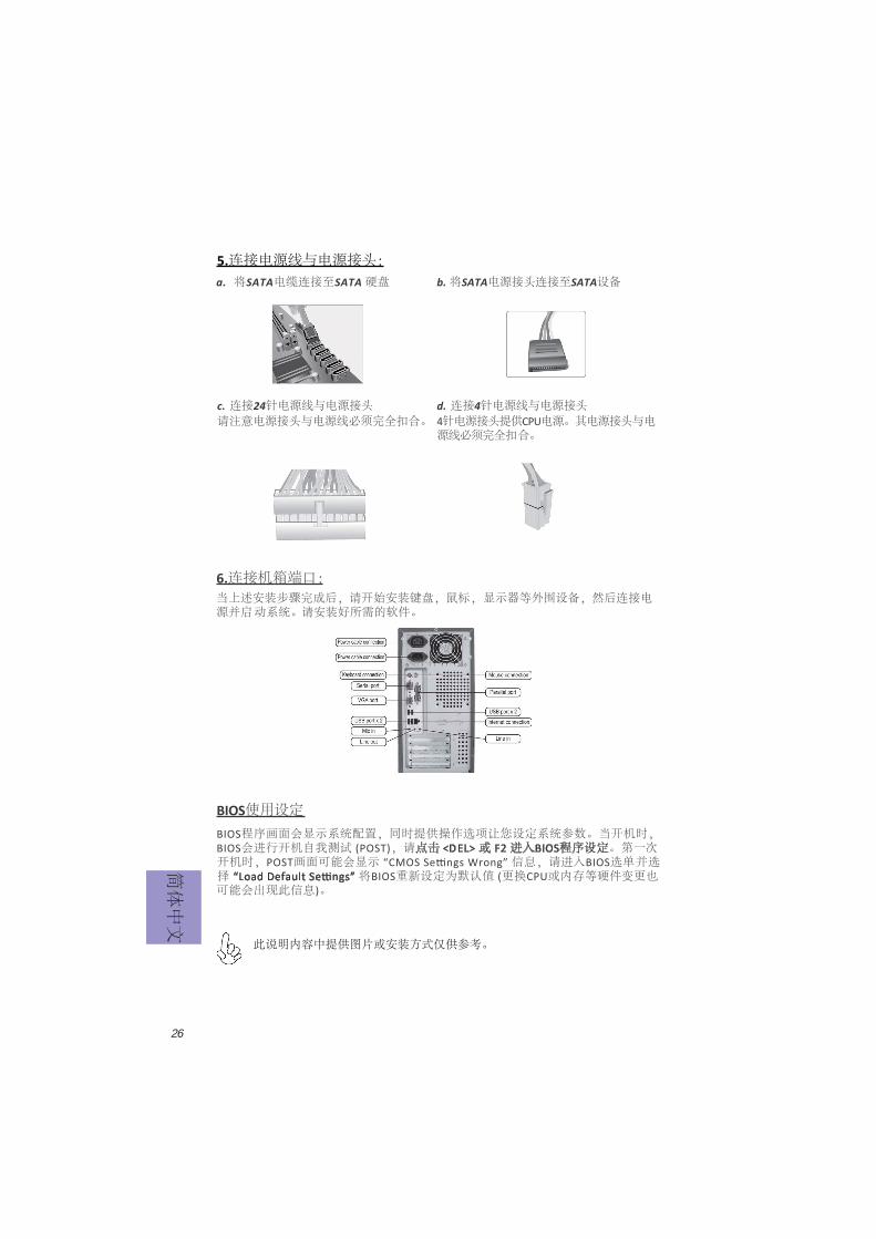
5.连接电源线与电源接头:
c. 连接24针电源线与电源接头4针电源接头提供CPU电源。其电源接头与电源线必须完全扣合。
b. 将SATA电源接头连接至SATA设备a. 将SATA电缆连接至SATA 硬盘
d. 连接4针电源线与电源接头请注意电源接头与电源线必须完全扣合。
简体中文
26
当上述安装步骤完成后,请开始安装键盘,鼠标,源并启
显示器等外围设备,然后连接电动系统。请安装好所需的软件。
6.连接机箱端口:
此说明内容中提供图片或安装方式仅供参考。
BIOS使用设定BIOS程序画面会显示系统配置,同时提供操作选项让您设定系统参数。当开机时,BIOS会进行开机自我测试 (POST),请点击 <D EL> 或 F2 进入BIOS程序设定。第一次开机时,POST画面可能会显示 信息,请进入BIOS选单并选择 将BIOS重新设定为默认值 (更换CPU或内存等硬件变更也可能会出现此信息)。
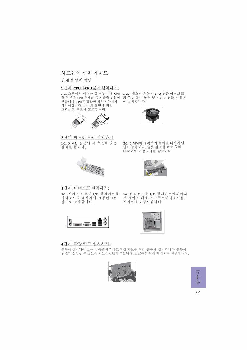
모듈 설치하기:
1단계. CPU와 CPU
하드웨어 설치 가이드 단계별 설치 방법
1-1. 소켓에서 레버를 뽑아 냅니다.
2단계. 메모리 2-1. D I M M 슬롯의 각 측면에 있는 걸쇠를 풉니다 .
3단계. 마더보드 설치하기:3-1. 케이스의 후면 I / O 플레이트를 마더보드의 패키지에 제공된 I / O
실드로 교체합니다 .
CPU 끝 부분을 CPU 소켓의 들어간 끝 부분에 맞춥니다. CPU를 정확한 위치에 살며시
위치시킵니다. CPU의 표면에 써멀 그리스를 고르게 도포합니다.
1-2. 패스너를 돌려 CPU 팬을 마더보드의 쓰루-홀에 눌러 넣어 CPU 팬을 제 위치에 설치합니다.
2-2. DIMM이 정확하게 설치될 때까지 단단히 누릅니다. 슬롯 걸쇠를 위로
DIMM의 가장자리를 잠급니다..
3-2. 마더보드를 I / O 플레이트에 위치시켜 케이스 내에.
스크류로
마더보드를
케이스에 고정시킵니다 .
쿨러 설치하기:
한국어
27
올려
4단계. 확장 카드 설치하기: 슬롯에 설치되어 있는 금속을 제거하고 확장 카드를 해당 슬롯에 삽입합니다. 슬롯에 완전히 삽입될 수 있도록 카드를 단단히 누릅니다. 스크류를 다시 제 자리에 체결합니다.

5단계. 케이블 및 전원 커넥터 연결하기:
c. 4핀 전원 케이블을 연결합니다ATX_12V 4핀 전원 커넥터는 전원을 CPU에 공급하기 위해 사용됩니다. 4핀 전원 케이블 설치시에는, 전원 케이블의 걸쇠가 ATX_12V 커넥터와 완벽하게 맞아야 합니다.
b. SATA 전원 커넥터를 SATA 장치에 연결합니다
a. SATA 하드 드라이브를 SATA 케이블에 연결합니다
d. 4핀 전원 케이블을 연결합니다24핀 전원 케이블 연결시 전원 케이블과 ATX 커넥터의 걸쇠가 완벽하게 맞아야 합니다.
한국어
28
일단 위의 단계들이 완료되면, 키보드, 마우스, 모니터 등과 같은 주변기기들을
연결합니다. 그런 후에, 전원을 연결하고 시스템을 켭니다. 모든 필수 소프트웨어를 설치합니다.
6단계. 케이스의 포트 연결하기:
BIOS 사용하기BIOS 셋업 유틸리티 는 시스템의 환경설정 상태를 표시하며 시스템 매개변수를 설정하기 위한 옵션을 제공합니다. 시스템의 전원을 켜면, BIOS는 Power-On Self Test (POST) 루틴을 실행합니다 , <DEL> 또는 F2를 눌러 셋업으로 들어가십시.오 처음으로 전원을 켜면 POST 화면에 메시지가 나타날 수 있습니다 . BIOS로 들어가 을 선택하여 기본 CMOS 설정값을 재설정합니다. (CPU, 메모리 등과 같은 시스템 변경할 때에도 본 메뉴가
나타날 수 있습니다.)
설치절차는 사용된 케이스 및 장치의 유형에 따라 다를 수 있습니다.