brief user guide diamond 42 - afm solutions · brief user guide diamond 42 ... the software makes...
TRANSCRIPT

Brief User Guide
Diamond 42
For program installation help please see http://www.afmsolutions.com/installing.html
For getting started help please see http://www.afmsolutions.com/ipadiphone.html
When starting the app for the first time you’ll have to accept the license agreement in order to continue.
When the app is started, it always shows the Main Menu page as illustrated below. Here, you can tap the Weight & Balance button, Landing button or Takeoff button.
There are several options for the app’s background color. Under different lighting conditions certain options
may work better than others. The textured background works great in bright daylight, but a darker grey
works better in low light situations.
© 2009-2015 AFM Solutions

Weight and Balance
Tap the “Weight & Balance” button on the main menu to jump to the Weight and Balance form. Then, you can either begin by typing the passengers’ weight values or you can use the quick fill method. To begin entering numbers tap on a white input box of your choice, for example Seat 1 or Front Seat L:
A built-in keypad will appear so you can start typing. To move to the next box press the “Next” button:
© 2009-2015 AFM Solutions
Passenger and baggage weight values
are in kilograms.
The user can select the Fuel Quantity
units to be either in kilograms or in US
Gallons.
In this example the main tank contains
30 US gallons of fuel on takeoff and it
contains 15,9 gallons on landing.
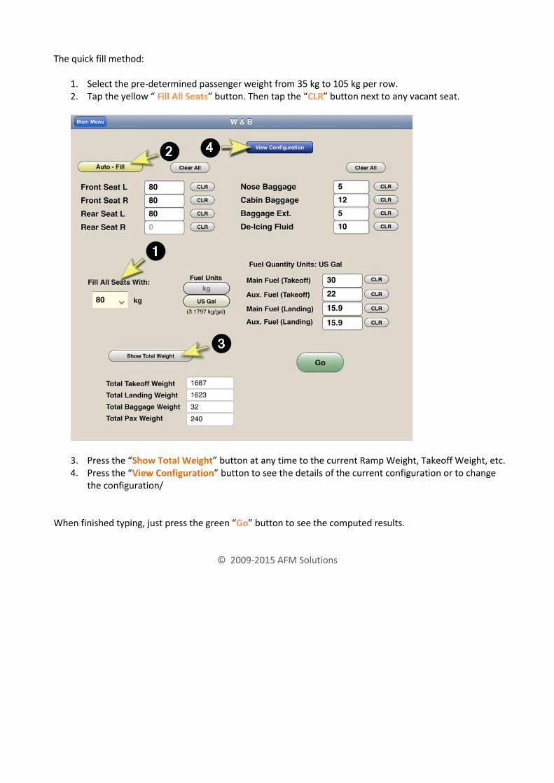
The quick fill method:
1. Select the pre-determined passenger weight from 35 kg to 105 kg per row. 2. Tap the yellow “ Fill All Seats” button. Then tap the “CLR” button next to any vacant seat.
3. Press the “Show Total Weight” button at any time to the current Ramp Weight, Takeoff Weight, etc. 4. Press the “View Configuration” button to see the details of the current configuration or to change
the configuration/ When finished typing, just press the green “Go” button to see the computed results.
© 2009-2015 AFM Solutions
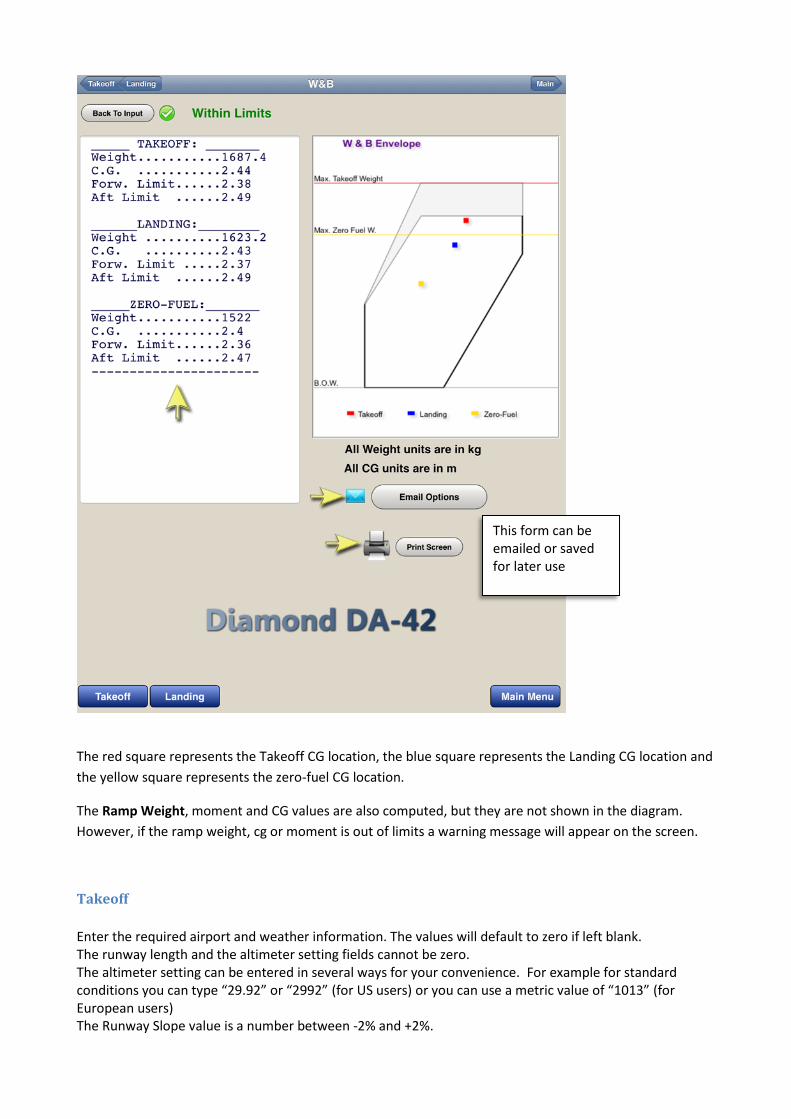
The red square represents the Takeoff CG location, the blue square represents the Landing CG location and
the yellow square represents the zero-fuel CG location.
The Ramp Weight, moment and CG values are also computed, but they are not shown in the diagram.
However, if the ramp weight, cg or moment is out of limits a warning message will appear on the screen.
Takeoff
Enter the required airport and weather information. The values will default to zero if left blank. The runway length and the altimeter setting fields cannot be zero. The altimeter setting can be entered in several ways for your convenience. For example for standard conditions you can type “29.92” or “2992” (for US users) or you can use a metric value of “1013” (for European users) The Runway Slope value is a number between -2% and +2%.
This form can be emailed or saved for later use

1. If the “Use Proposed Weight” box is checked, the program will use the weight found in the “Proposed Weight” box. If left unchecked, the program will find the maximum allowable takeoff weight for the given conditions. 2. If the resulting takeoff weight is limited then there will be a warning message at the top. 3. Press the “View Details” button to see the details of all the weight limitations encountered as it relates to EASA requirements. The wind corrections include 50% factored headwind and 150% factored tailwind, as required.

Takeoff with an obstacle present:
1. If there are no obstacles to clear and no required SID gradient, press the “None” button. 2. If there is an obstacle, enter the obstacle height above the runway in meters. Then enter the obstacle’s distance from the end of the runway in meters. The software makes sure that the net single-engine climb gradient clears the obstacle by at least 50 feet. If the takeoff weight is limited by runway length due to EASA minimum requirements then there will be a warning message at the top of the form. Pressing the “View Details” button will bring up the Takeoff Data Details box: (See example below)

The main values are then displayed in the details box. To close this box, just tap anywhere inside the box.
© 2009-2014 AFM Solutions

Landing
If the aircraft has to make an emergency landing immediately after takeoff, you can quickly transfer all the airport and weather information from the takeoff form into the landing form by pressing the “Copy T.O. Data” button near the top of the form.
If the “Weight” box is left blank, the program will use the structural maximum landing weight allowed. If any of the Landing Distance results are out of range there will be a warning message shown in red. In the example above, the landing distance of 665 m is less than the runway length of 1200 m, so consequently we see a green checkmark next to the landing weight. When the weight is not entered in the weight box, the program automatically uses the maximum landing weight allowed. Other Landing Limitations If the 70% factored landing distance is greater than the runway length of 1200 m then there will be a warning message. If a climb gradient value is too low, there will be a message (see picture below)

The landing weight must be lowered slightly in order to meet this requirement.
The Single-Engine
climb gradient must
be at least 0,75% at
1500 feet above
airport altitude.
In this example the
gradient is 0,71%
which is too low.

Aircraft Configuration (Weight and Balance)
To view or modify the aircraft configuration, press the “View Configuration” button near the top of the weight and balance form. The W&B configuration form will show.
To return back to the weight & balance form, press the blue “Return” button. To save your changes press the blue “Save” button. Here, you can change the number of seats present in your aircraft, the number of baggage areas present, B.O.W. weight etc. 1. This box lets you select how many passenger seats your aircraft uses. 2. You can rename the seats or baggage areas if needed. For example if the first seat is the Pilot-In-Command seat, just tap the seat 1 box and change it to “Pilot PIC”. After you have made all the necessary changes, press the red “Save” button. Then return to the program.
© 2009-2015 AFM Solutions

The weight and balance output form shows the results. Detailed numerical results are on the left, and the graphical view with the CG envelope is on the right.
The Center of Gravity values
are shown here in meters
These results can be sent to
your iPad’s e-mail or to a
wireless printer

The user can add information to this form, such as flight number, route, Pilot in Command etc. Then press the “Update Form” button to add it to the form that will be e-mailed.
When ready to e-mail this form press the “Send” button. To return to Weight & Balance form, press the “Go Back” button.
Press this button to send this form to
your iPad’s e-mail program
Press this button to return to the
Weight & Balance Form

EASA (EU-OPS) Requirements
This software always checks if the following requirements are satisfied: Takeoff Ops 1.530 An operator shall ensure that the take-off mass does not exceed the maximum take-off mass specified in the Aeroplane Flight Manual for the pressure altitude and the ambient temperature at the aerodrome at which the take-off is to be made.
The unfactored take-off distance does not exceed:
(1) When multiplied by a factor of 1,25, the take-off run available; or
(2) When stop way and/or clearway is available, the following:
(i) The take-off run available;
(ii) When multiplied by a factor of 1,15, the take-off distance available; and
(iii) When multiplied by a factor of 1,3, the accelerate-stop distance available.
OPS 1.535 Take-off Obstacle Clearance
(a) take-off flight path, clears all obstacles by a vertical margin of at least 50 ft (1) The take-off flight path begins at a height of 50 ft above the surface at the end of the take-off distance required by OPS 1.530 (b) and ends at a height of 1 500 ft above the surface; (5) The gradient of the take-off flight path is equal to the one engine inoperative.
OPS 1.540 En-Route – Multi-engined aeroplanes (a) in the event of the failure of one engine, with the remaining engines operating within the maximum continuous power conditions specified, is capable of continuing flight at or above the relevant minimum altitudes for safe flight stated in the Operations Manual to a point 1000 ft above an aerodrome. (1) The aeroplane can achieve a rate of climb of at least 300 ft per minute with all engines operating within the maximum continuous power conditions specified; The corresponding charts in the aircraft flight manual show that the above condition is always true for aerodrome altitudes between sea level and 15000 feet.
Landing OPS 1.550
The landing mass of the aeroplane determined in accordance with OPS 1.475 (a) does not exceed the maximum landing mass specified for the altitude and the ambient temperature expected for the estimated time of landing at the destination and alternate aerodrome.
OPS 1.550 Landing – Dry runway
(a) The landing mass of the aeroplane determined in accordance with OPS 1.475 (a) for the estimated time of landing
allows a full stop landing from 50 ft above the threshold within 70 % of the landing distance available at
the destination aerodrome and at any alternate aerodrome.
Appendix 1 to OPS 1.525 (b) General – Take-off and Landing Climb
(a) Take-off Climb
(1) All Engines Operating
(i) The steady gradient of climb after take-off must be at least 4 % with:

(A) Take-off power on each engine;
(B) The landing gear extended except that if the landing gear can be retracted in not more than 7 seconds, it may be
assumed to be retracted;
(C) The wing flaps in the take-off position(s); and
(D) A climb speed not less than the greater of 1,1 VMC and 1,2 VS1.
(2) One Engine Inoperative
(i) The steady gradient of climb at an altitude of 400 ft above the take-off surface must be measurably positive with:
(A) The critical engine inoperative and its propeller in the minimum drag position;
(B) The remaining engine at take-off power;
(C) The landing gear retracted;
(D) The wing flaps in the take-off position(s); and
(E) A climb speed equal to that achieved at 50 ft.
(ii) The steady gradient of climb must be not less than 0,75 % at an altitude of 1 500 ft above the take-off surface
with:
(E) A climb speed not less than 1,2 VS1.
(b) Landing Climb
(1) All Engines Operating
(i) The steady gradient of climb must be at least 2,5 % with:
(A) Not more than the power or thrust that is available 8 seconds after initiation of movement of the power controls from
the minimum flight idle position;
(B) The landing gear extended;
(C) The wing flaps in the landing position; and
(D) A climb speed equal to VREF.
(2) One engine Inoperative
(i) The steady gradient of climb must be not less than 0,75 % at an altitude of 1 500 ft above the landing surface
with:
(A) The critical engine inoperative and its propeller in the minimum drag position;
(B) The remaining engine at not more than maximum continuous power;
(C) The landing gear retracted;
(D) The wing flaps retracted; and
(E) A climb speed not less than 1,2 VS1.
The software calculates the optimum takeoff weight with respect to the runway length and obstacle and climb requirements.
If any of the other requirements listed above is not met, there will be a warning message alerting the user to that effect.
If a landing requirement is not met, there will be a warning message alerting the user to that effect.

Weight and Balance or Mass and Balance:
The software calculates the weight (mass), the center of gravity and moment of the aircraft for:
Zero Fuel, Ramp, Takeoff and Landing conditions
If any of the computed values are found to be outside of the allowed limits, the program will display a warning message to the user.
www.afmsolutions.com / [email protected] / (325) 260-4720
© 2009-2015 AFM Solutions